James H
-
Posts
6,144 -
Joined
-
Last visited
Content Type
Profiles
Forums
Gallery
Events
Everything posted by James H
-
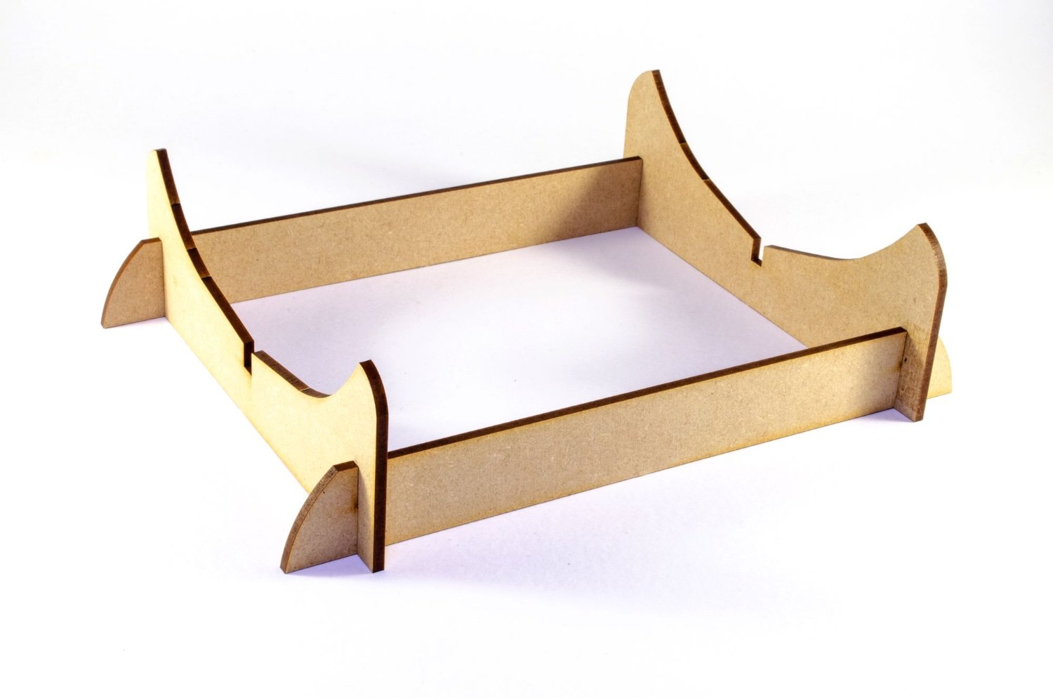
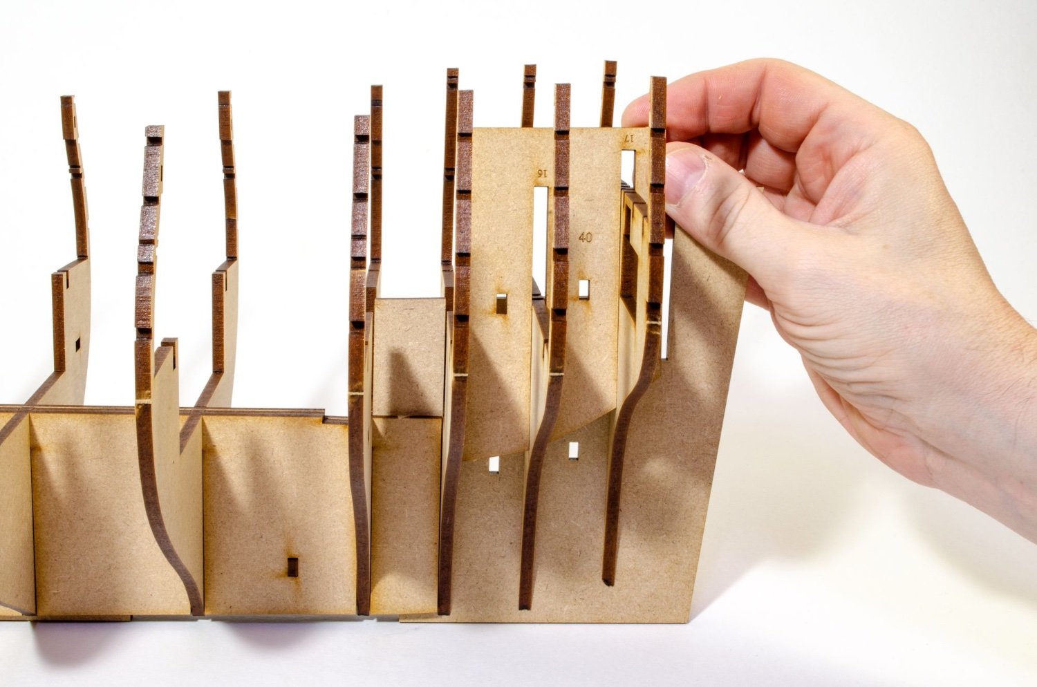
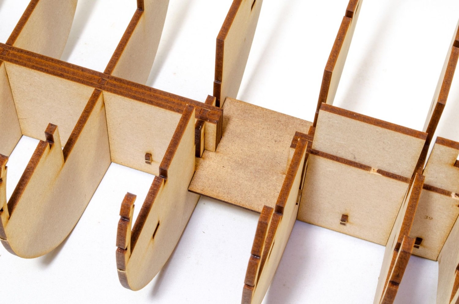
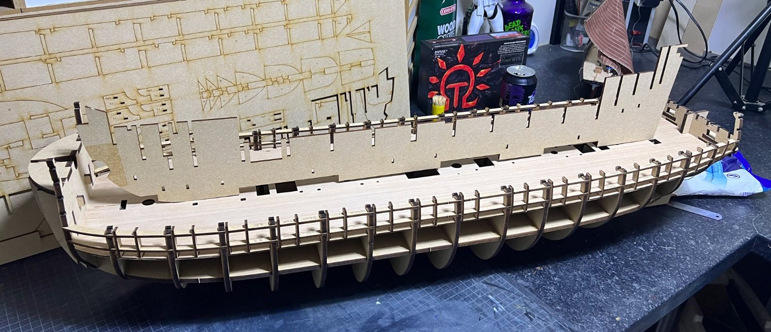
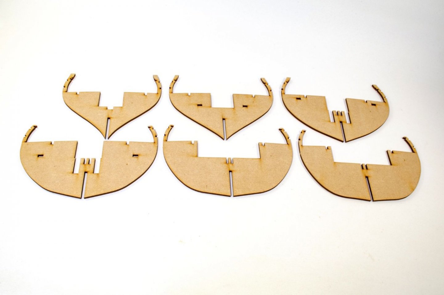
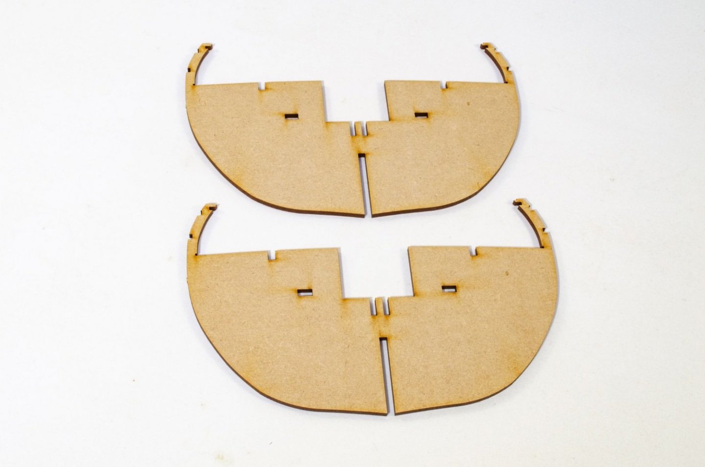
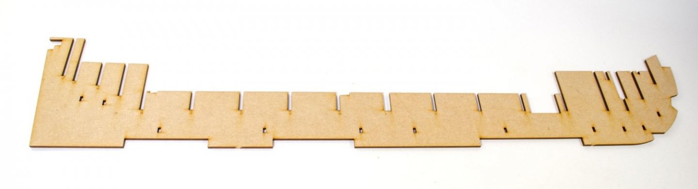
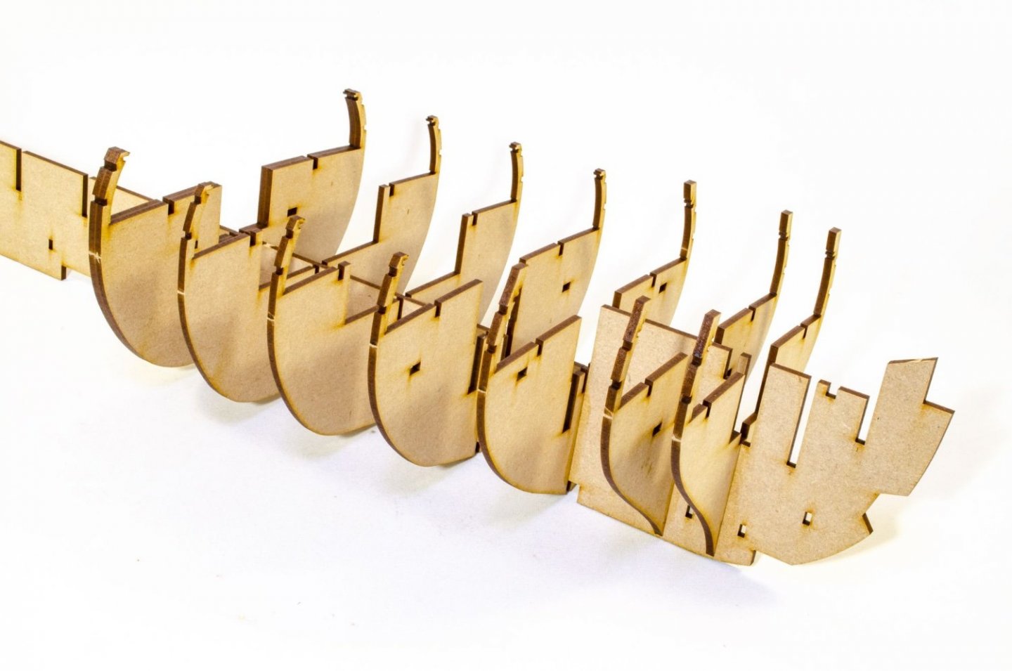
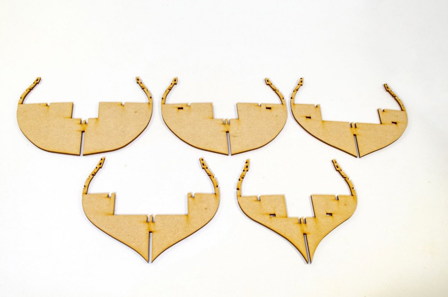
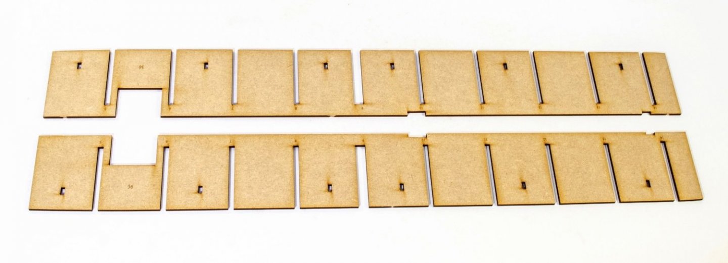
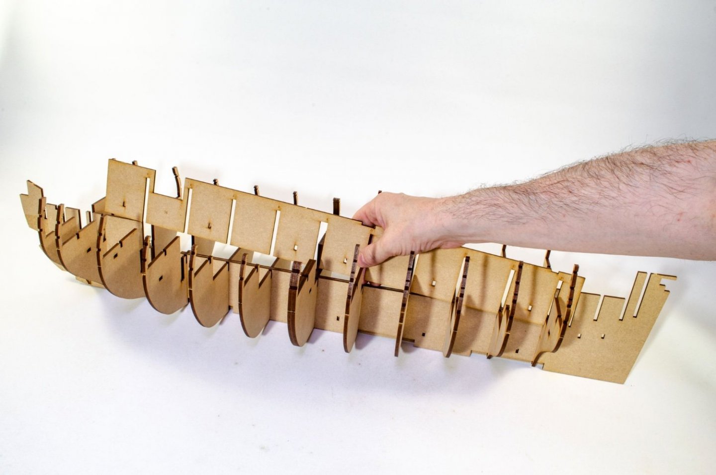
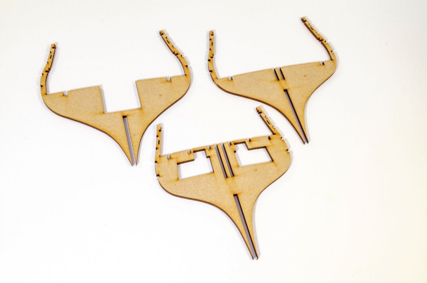
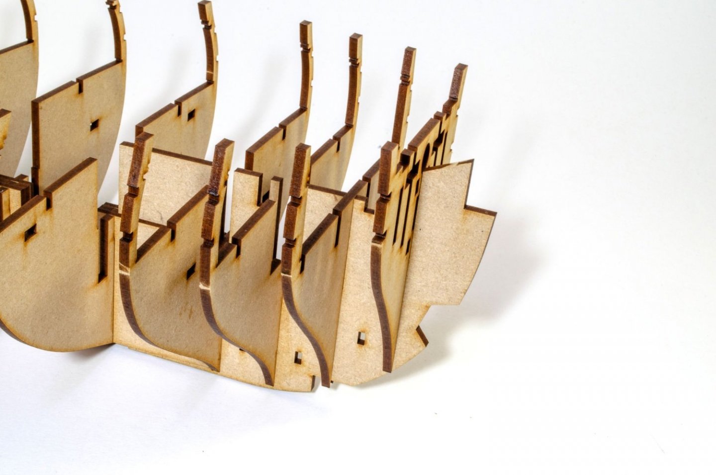
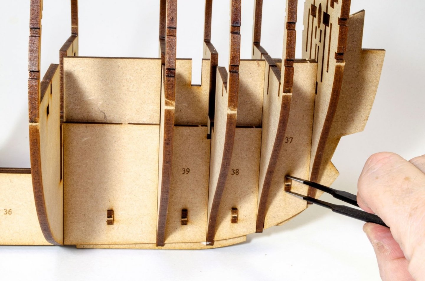
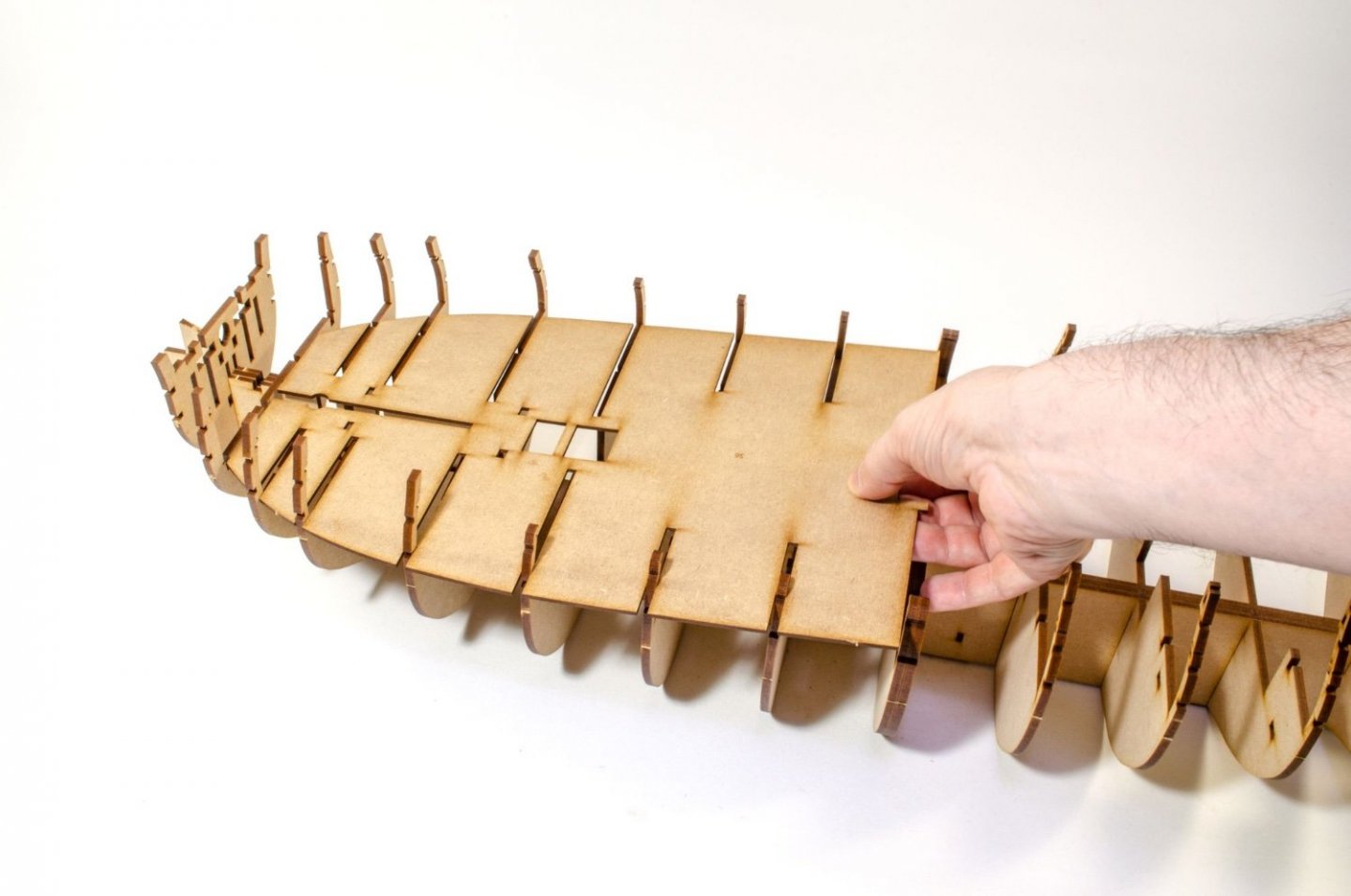
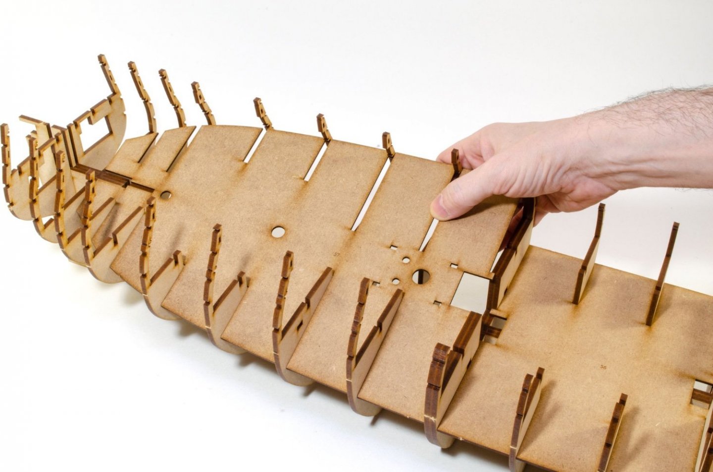
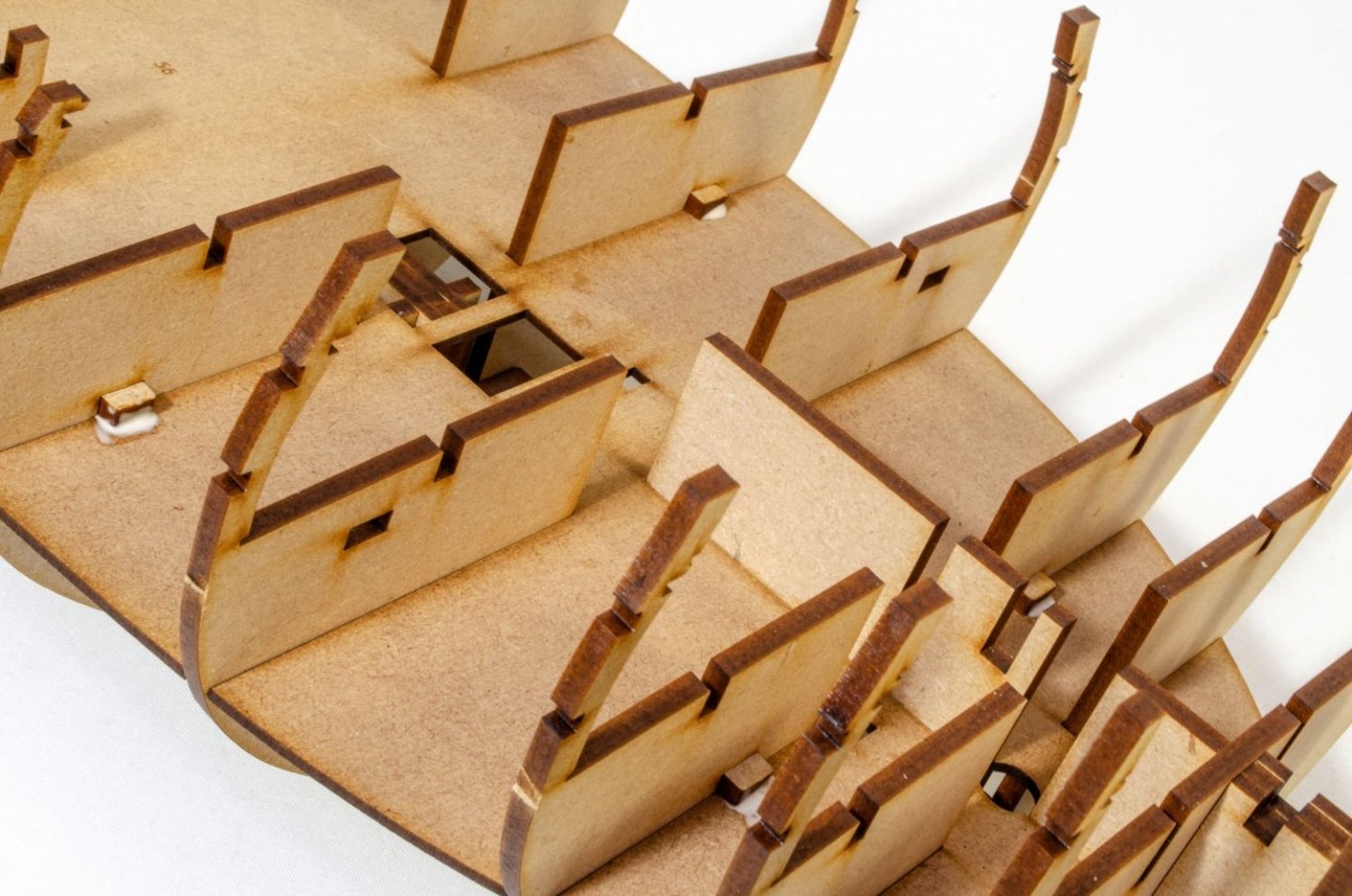
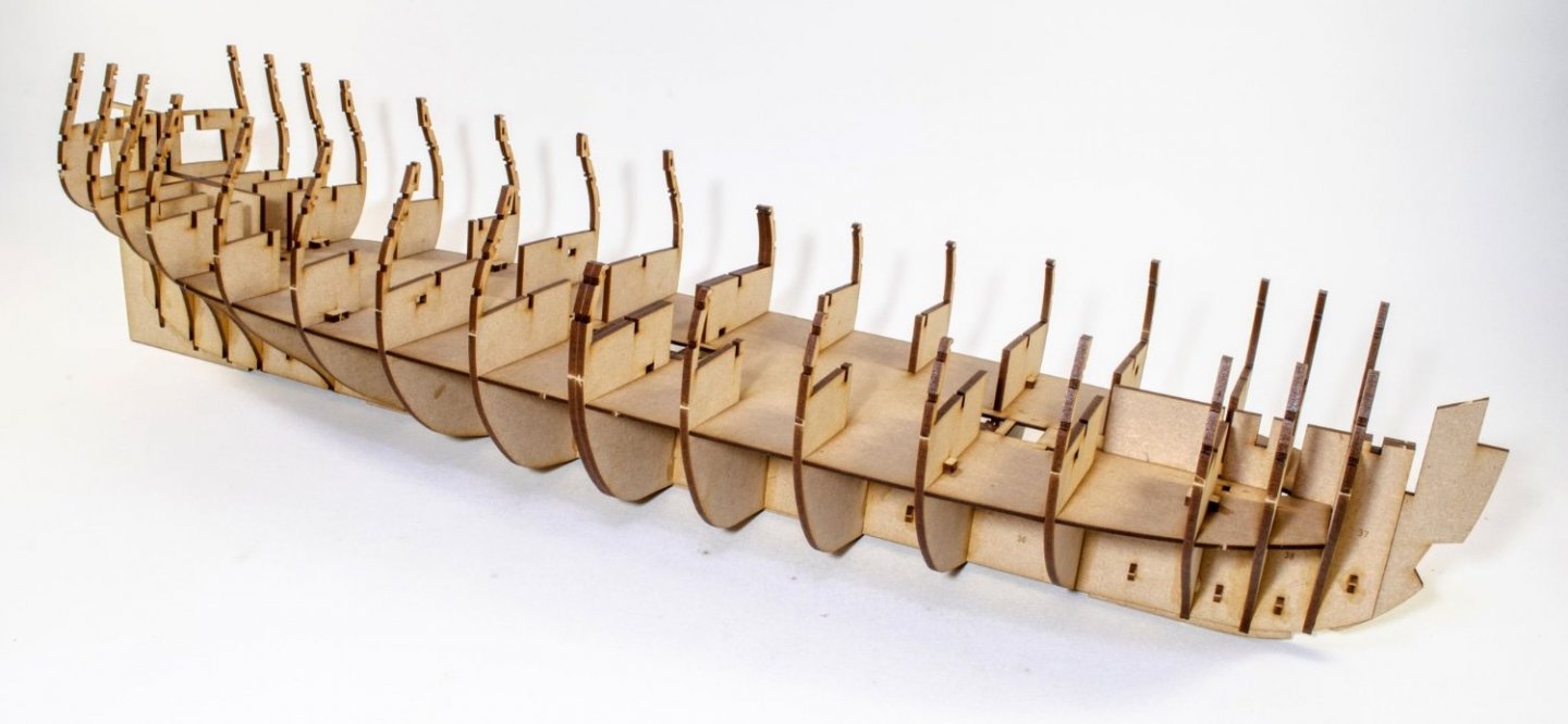
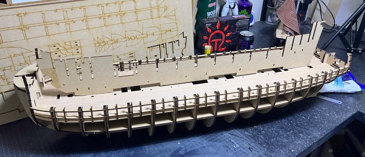
 Work has now begun. First, the obligatory disposable cradle shot 😃 Indy certainly isn't short of bulkheads. There are 18 in total, with #9 midships being a double layer bulkhead. There are no bevel marks on Indy. They simply aren't needed for a kit of this level. Fairing will be an easy task. All bulkheads are 4mm MDF, as is the keel. The keel slots are numbered too so you get things in the right place. Indy is a strange build in that practically all you see in this update, with the exception of lower deck/orlop detail, can be assembled initially with no glue. All bulkheads you see being added here are put into position as such. Now this is where the magic happens. Once all bulkheads (apart from #1, #2, #15, #16, #17 and #18 because they aren't needed yet) are slotted into their position, these keel doublers are added, bulking out the keel to 12mm! What these do is to hold the bulkheads in their exact position. while pegs slot through the holes to lock everything into position. Zero glue apart from the pegs themselves. Bulkheads #15, #16 and #17 are now added because the fairing parts will now lock them into position as with the other bulkheads. Bulkheads #1 and #2 are now fitted, but NO GLUE at this time. The fairing patterns are now added. You will see these as No.s 37, 38 and 39. Like the others, these are pegged into place. Is there an orlop deck? There certainly is. This is it 😆 Nothing more is needed. In fact, you'll probably not even see this without an endoscope. This part is glued into place. The 3mm MDF sub deck is now fitted. Care needs to be taken around the bulkhead ears. You should have no problem....just don't go charging in. To fit this, I ran some Titebond down the 12mm wide keel centreline. Nothing here needed to be weighted down or pinned. It fit perfectly with a reassuring push. Pegs are now pushed into position which give a further aid to making sure everything is level. At this stage, things look like this:
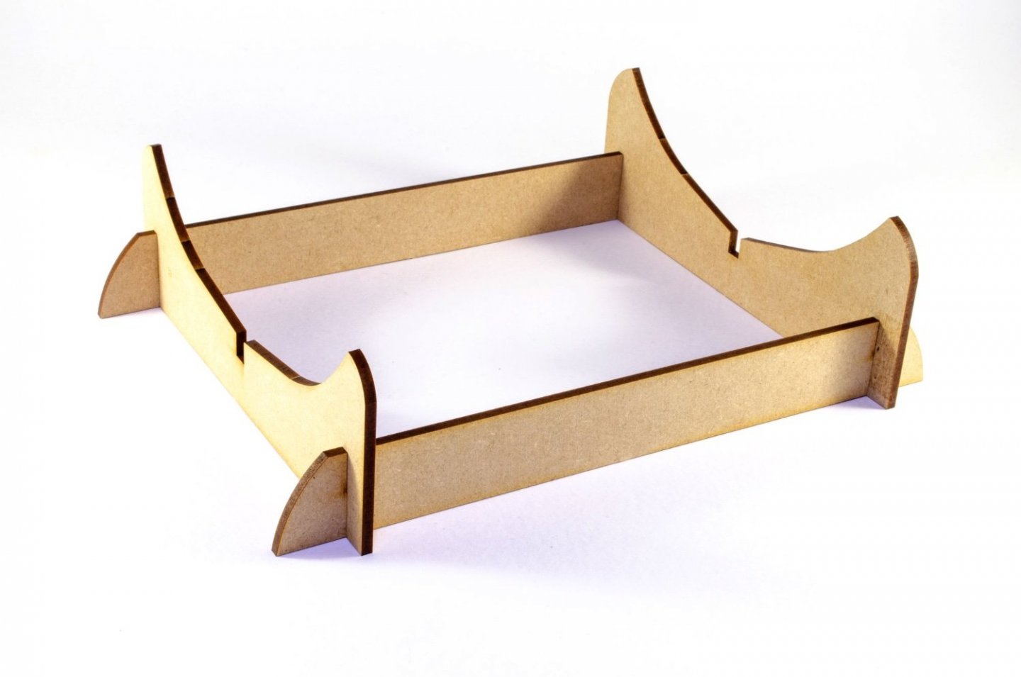


- 488 replies
-
- 39
-

-

-
- Indefatigable
- Vanguard Models
- (and 1 more)
-
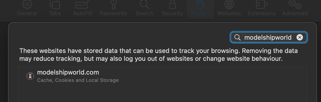
You should only need to search for data pertaining to this site, as I can on my Mac:
-
I will do some day, but they are all in attic storage at moment and its more effort than I have strength for at moment.
- 16 replies
-
- 2
-
-
- Ranger
- Vanguard Models
- (and 2 more)
-
Ok. We've had no system software changes at all for a while now, and as this seems to be very unusual, I can only surmise that the problem lies at your side. Please try to clear your browser cache and cookies, then restart your browser. This will force MSW to reload for you and not from a copy stored on your computer. Give that a try and see if it works.
-
I think you should definitely include that. It looks great 👍
- 857 replies
-
- 6
-
-

-
- Sphinx
- Vanguard Models
- (and 1 more)
-
Seizings - what am I doing wrong?
James H replied to David Lester's topic in Masting, rigging and sails
Use whatever works for you. There are no rules. If you use CA on stuff that has tension etc., just use regular viscosity so it seeps into the joint. Use sparingly so the majority soaks in and doesn't look rough. If you get any residue etc., then use a little black acrylic to touch up and hide. -
That's PayPal who do that, and not Chris. Depending on your region, that option WILL be available to you. When you choose that option, Chris is paid in full, and your contract is then with Paypal.
-
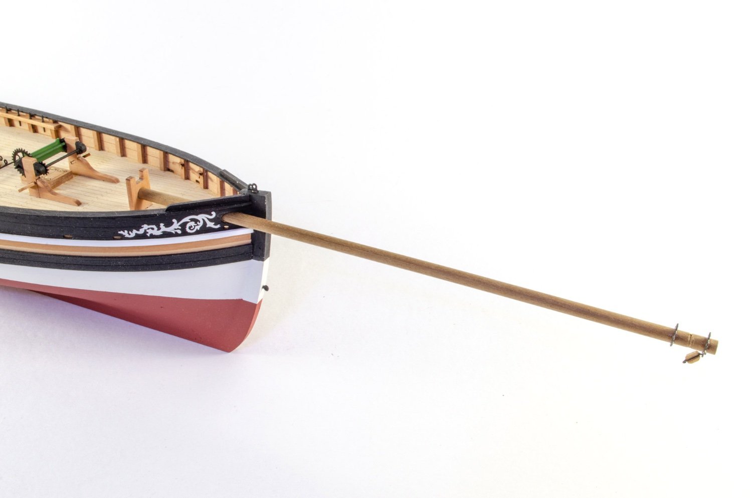
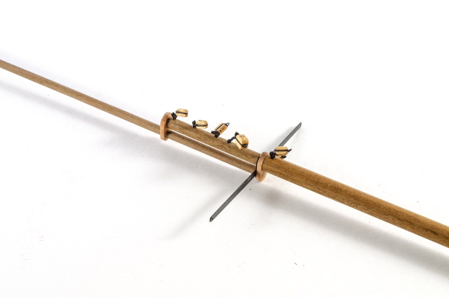
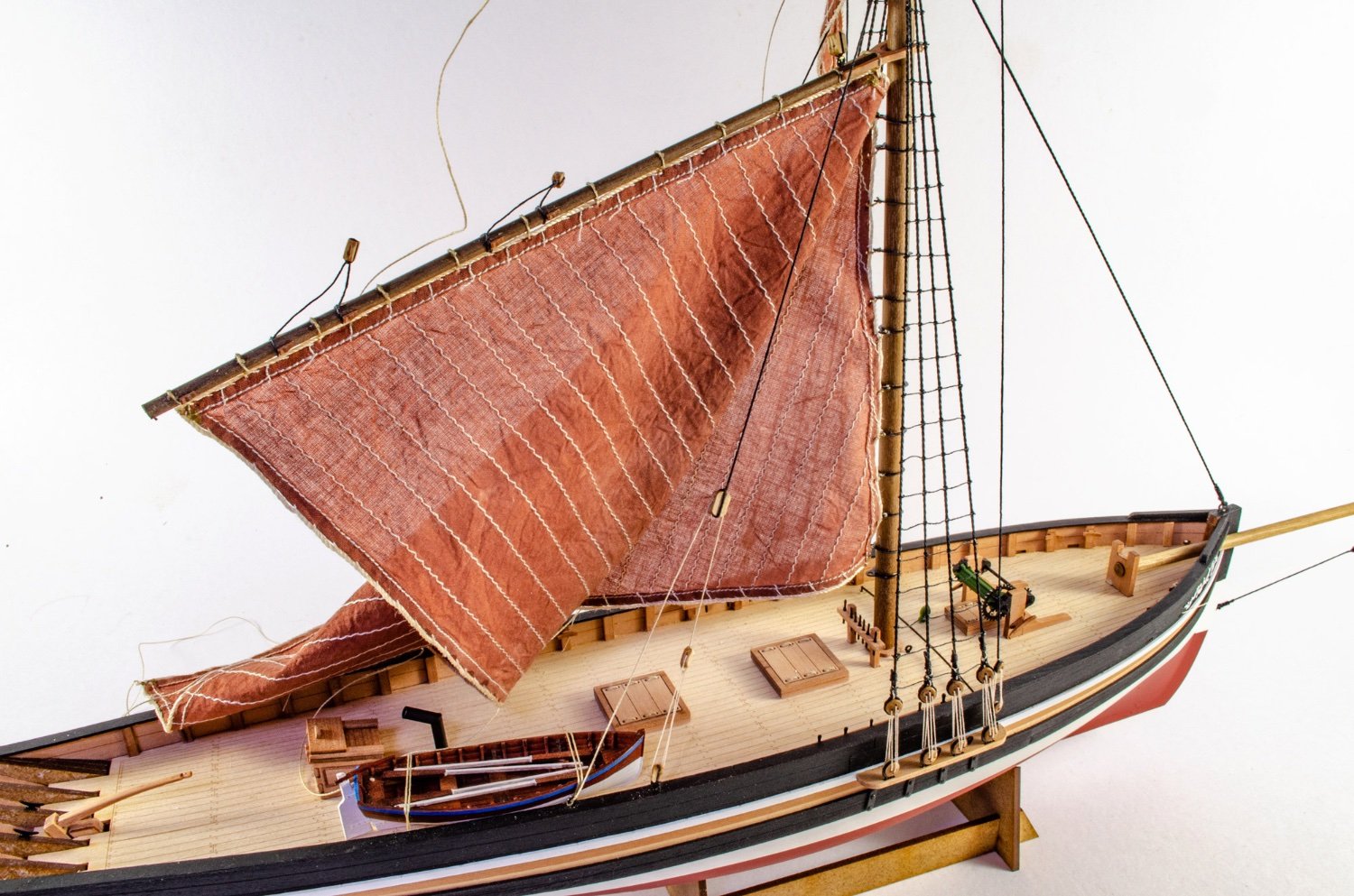
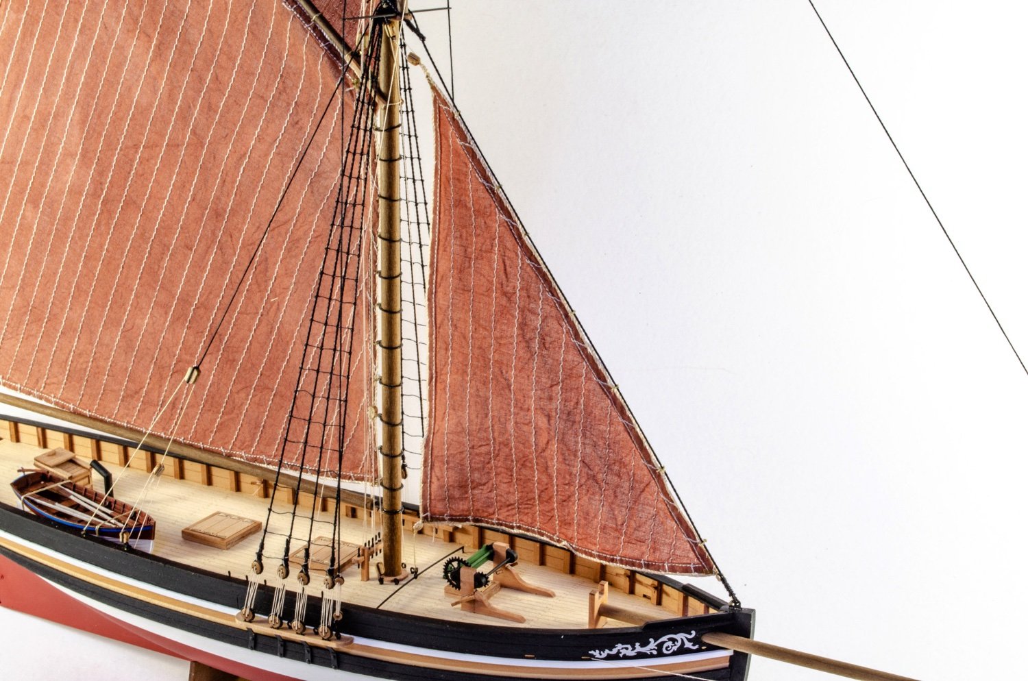
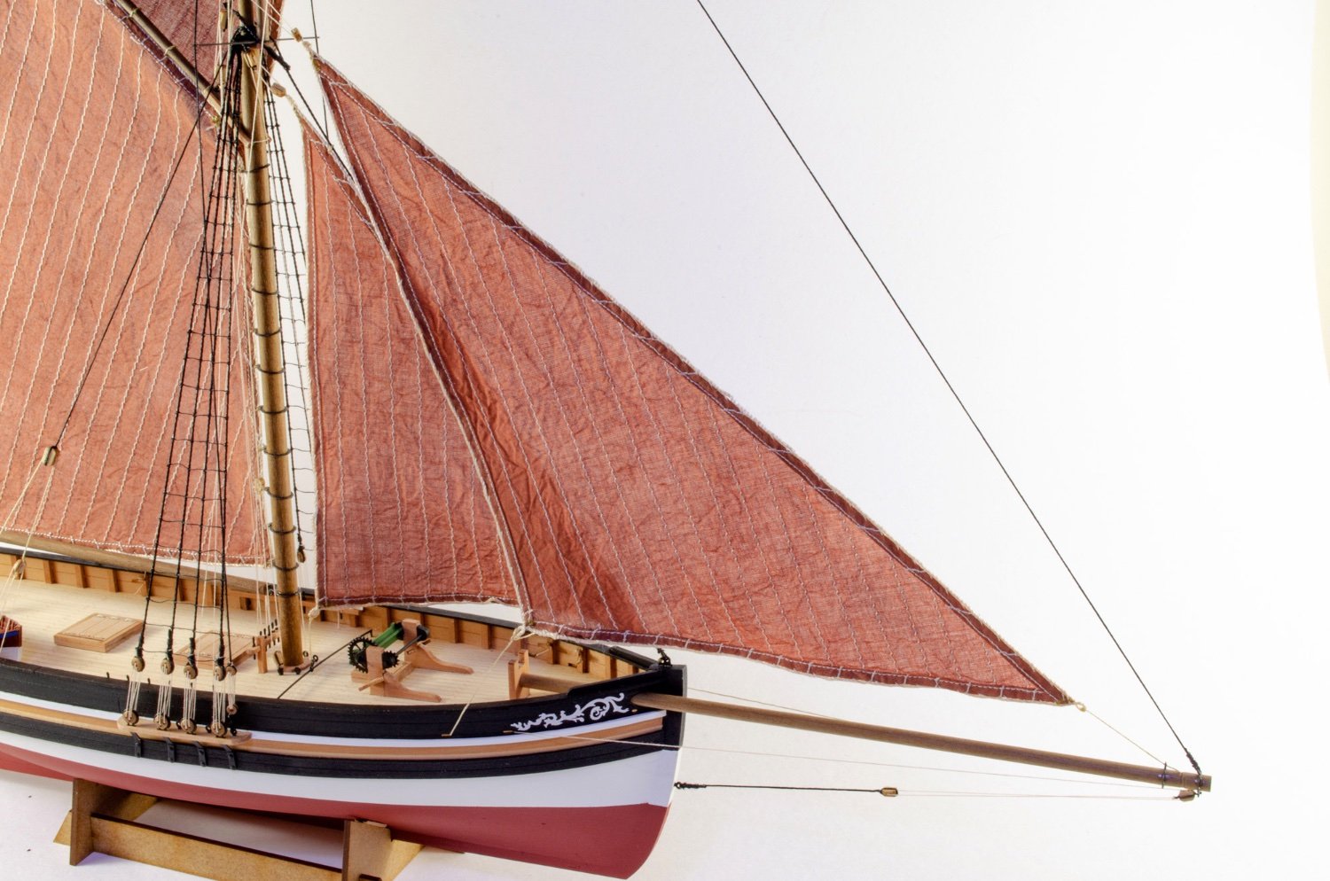
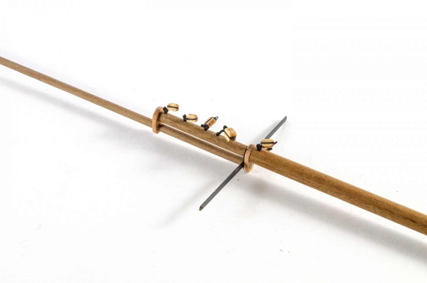
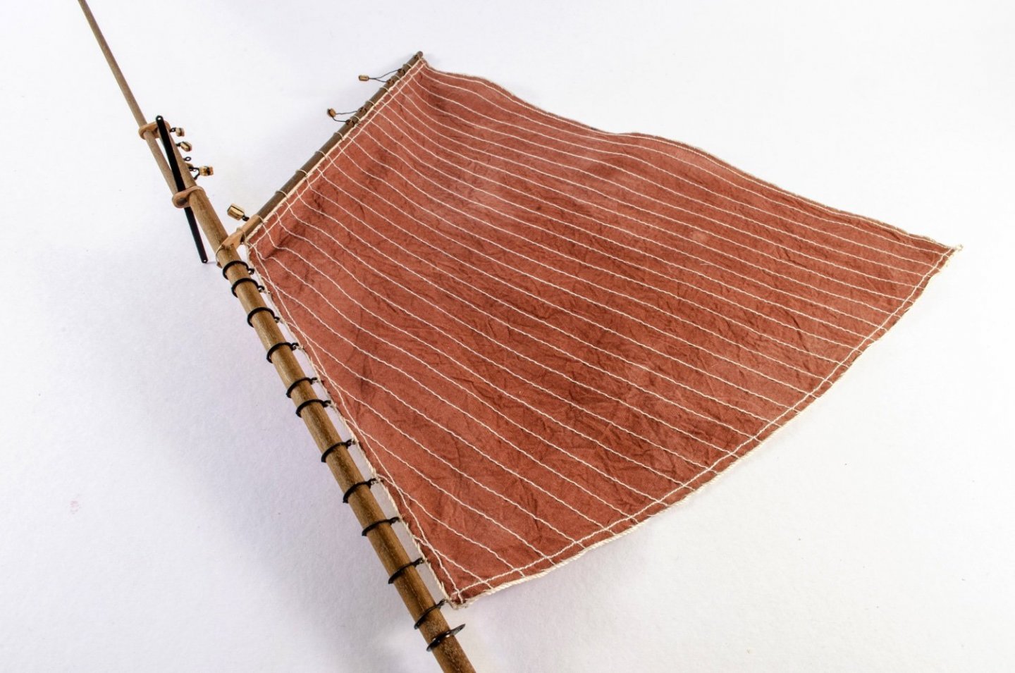
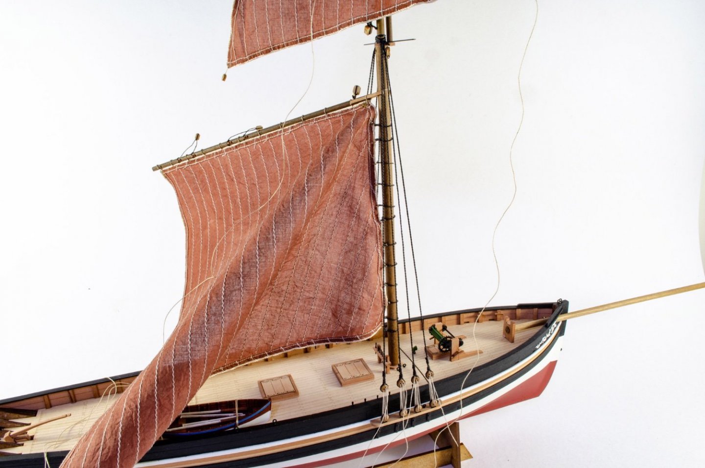
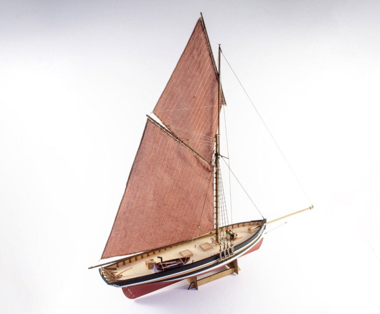
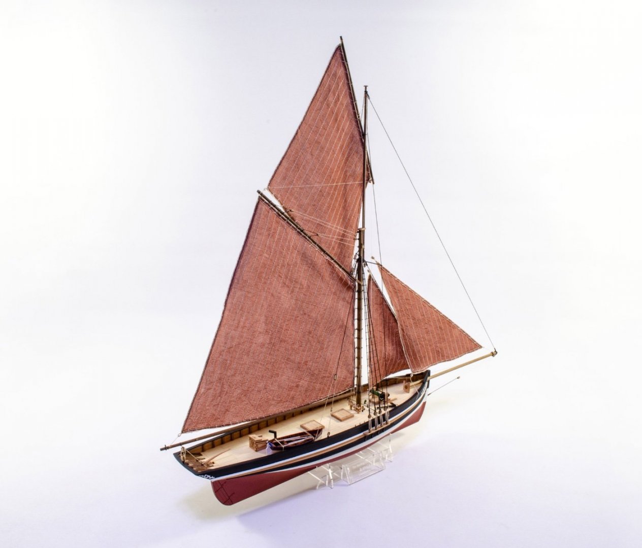
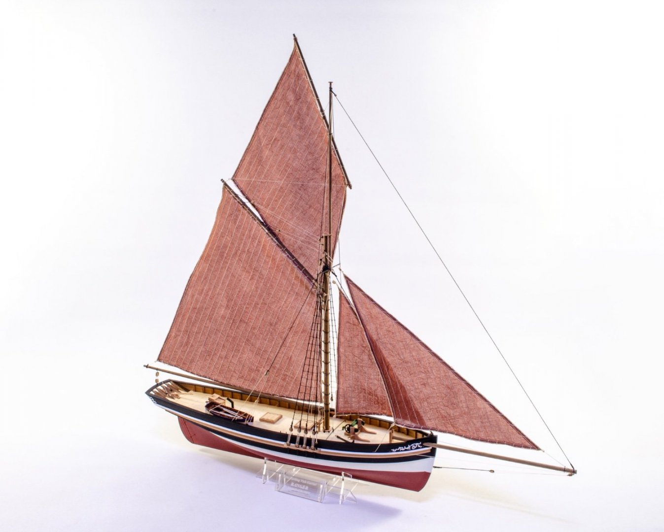
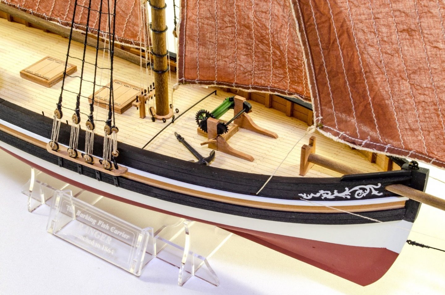
Ranger is now completed. It's taken me well over 2 weeks longer than I expected due to illness, hospital etc! This has been a beautiful model to build and very, very easy. Nothing here is at all taxing and she's perfect for anyone who's never built a model before, as are all the fisher kits. I do very much like this one though. I do find them easy after doing six of the fishers though! Anyway, here we go. These photos are very self-explanatory. Here she is, now finished. The little boat on deck does come with the kit too.


- 16 replies
-
- 15
-
-
-
- Ranger
- Vanguard Models
- (and 2 more)
-
I use thinned PVA for mine. Just a drop of water in a little squeeze bottle filled with PVA.
-
Also remember, the decor, pillars and relief will be ochre on a black background.
-
Out of a potential 16kg pack, the mast/rig stuff isn't going to make much of a dent in things.
-
You'll see a few new techniques in Indy too, such as for the construction of the cathead knees. You'll see more when that time comes
-
Hull length is around 880mm, I'm told. (minus bowsprit)
- 488 replies
-
- 6
-
-
- Indefatigable
- Vanguard Models
- (and 1 more)
-
This photo gives a rough idea of the size of Indefatigable to Amati's 1:64 Victory.
- 488 replies
-
- 25
-
-
-
- Indefatigable
- Vanguard Models
- (and 1 more)
-
In all fairness, can that engraving be trusted as evidence? After all, it shows round gun ports on the quarter too. Also all main gun deck ports seems to be lidded on that illustration.

- 488 replies
-
- 4
-
-
- Indefatigable
- Vanguard Models
- (and 1 more)
-
That is a certainty! The manual for Sphinx is 152 pages with about 1000 photos and 27500 words. Over 900 construction stages. I think Indy will easily top that with another 50+ pages. It remains to be seen yet, but there are no corners being cut whatsoever.
- 488 replies
-
- 16
-
-
- Indefatigable
- Vanguard Models
- (and 1 more)
-
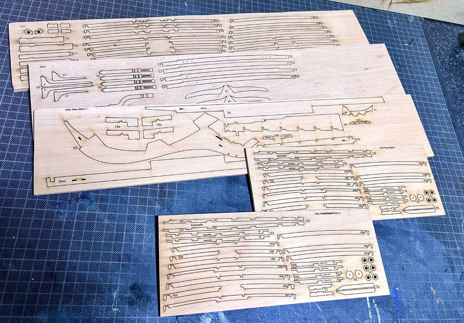
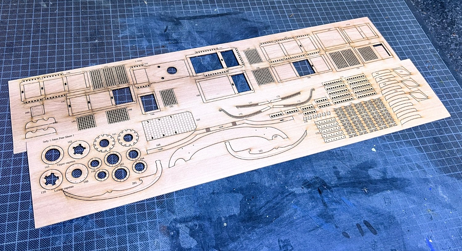
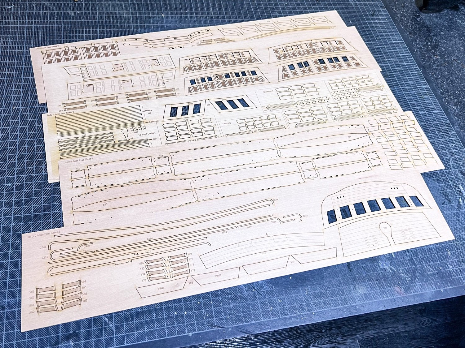
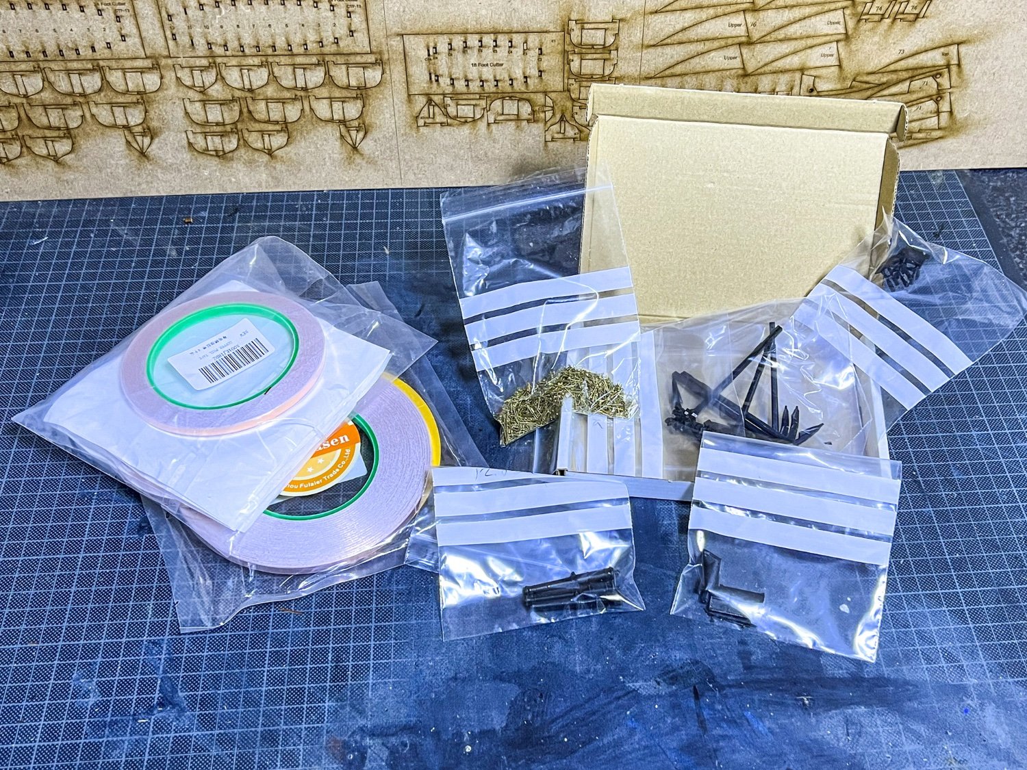
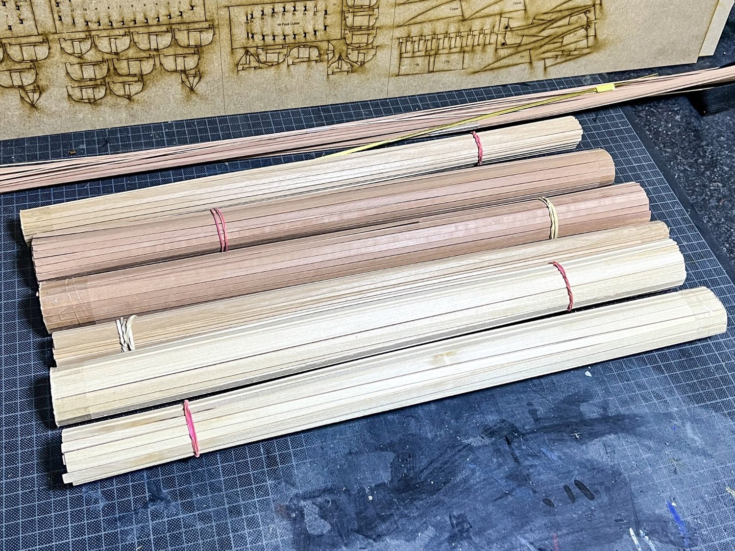
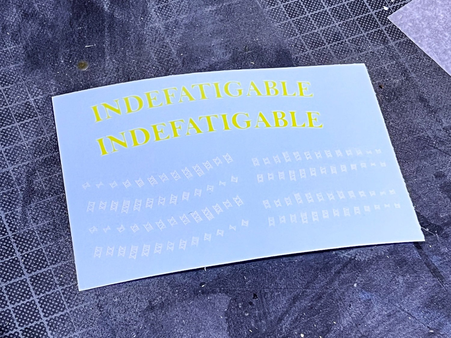
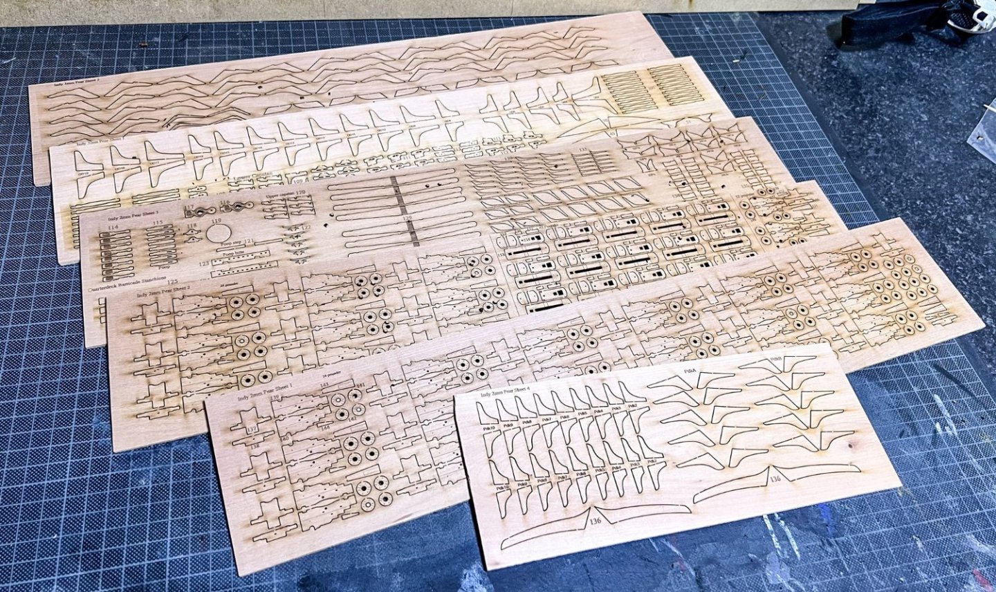
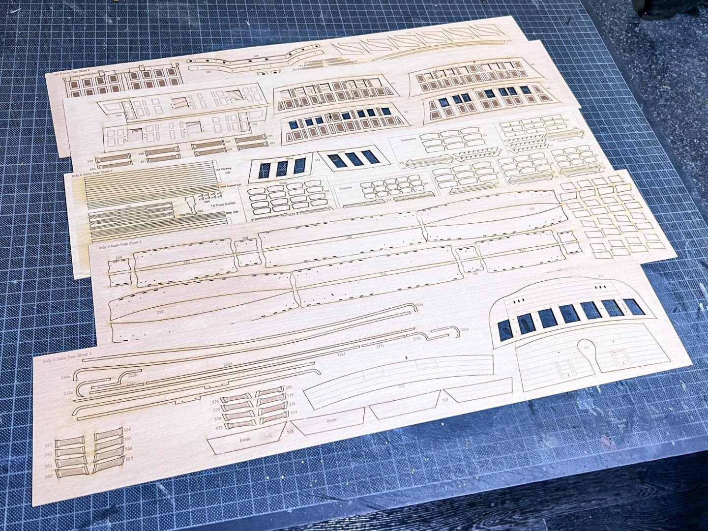
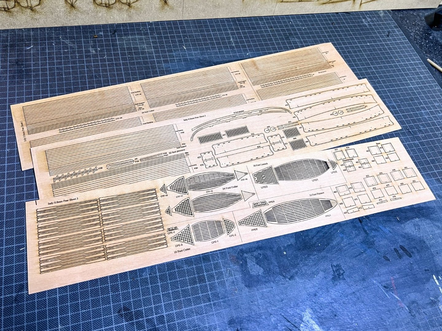
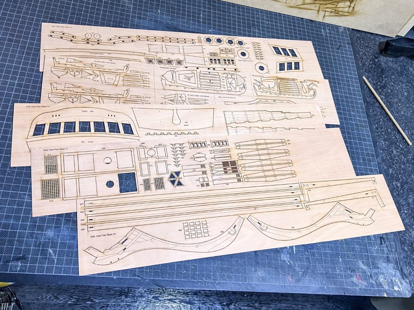
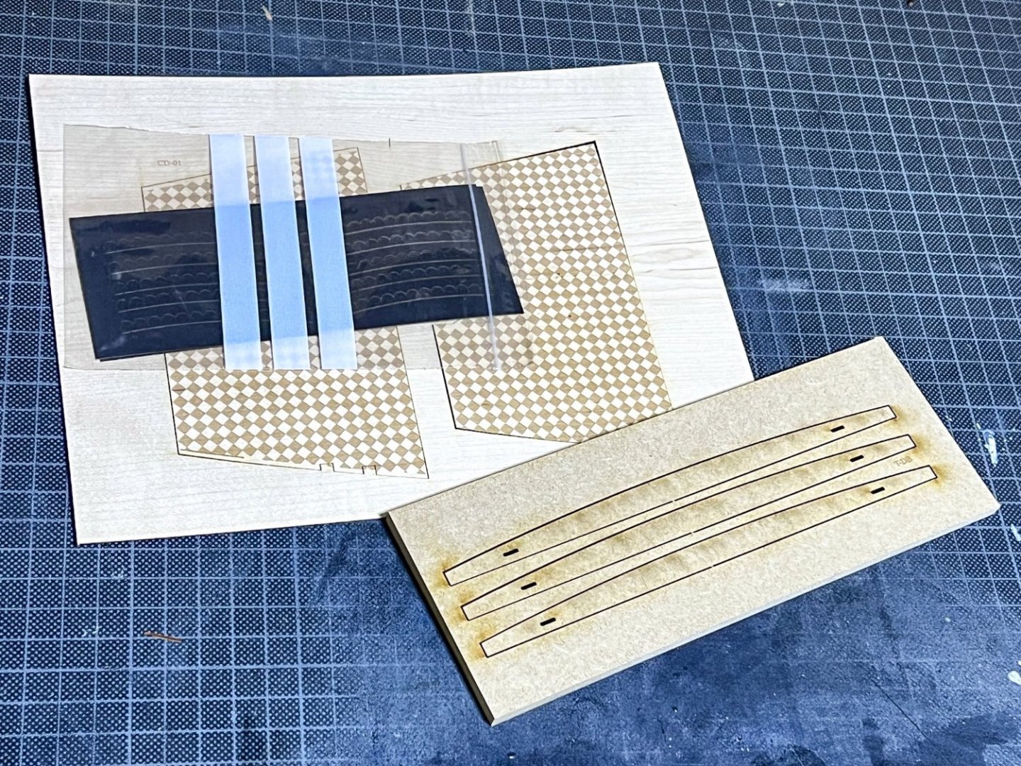
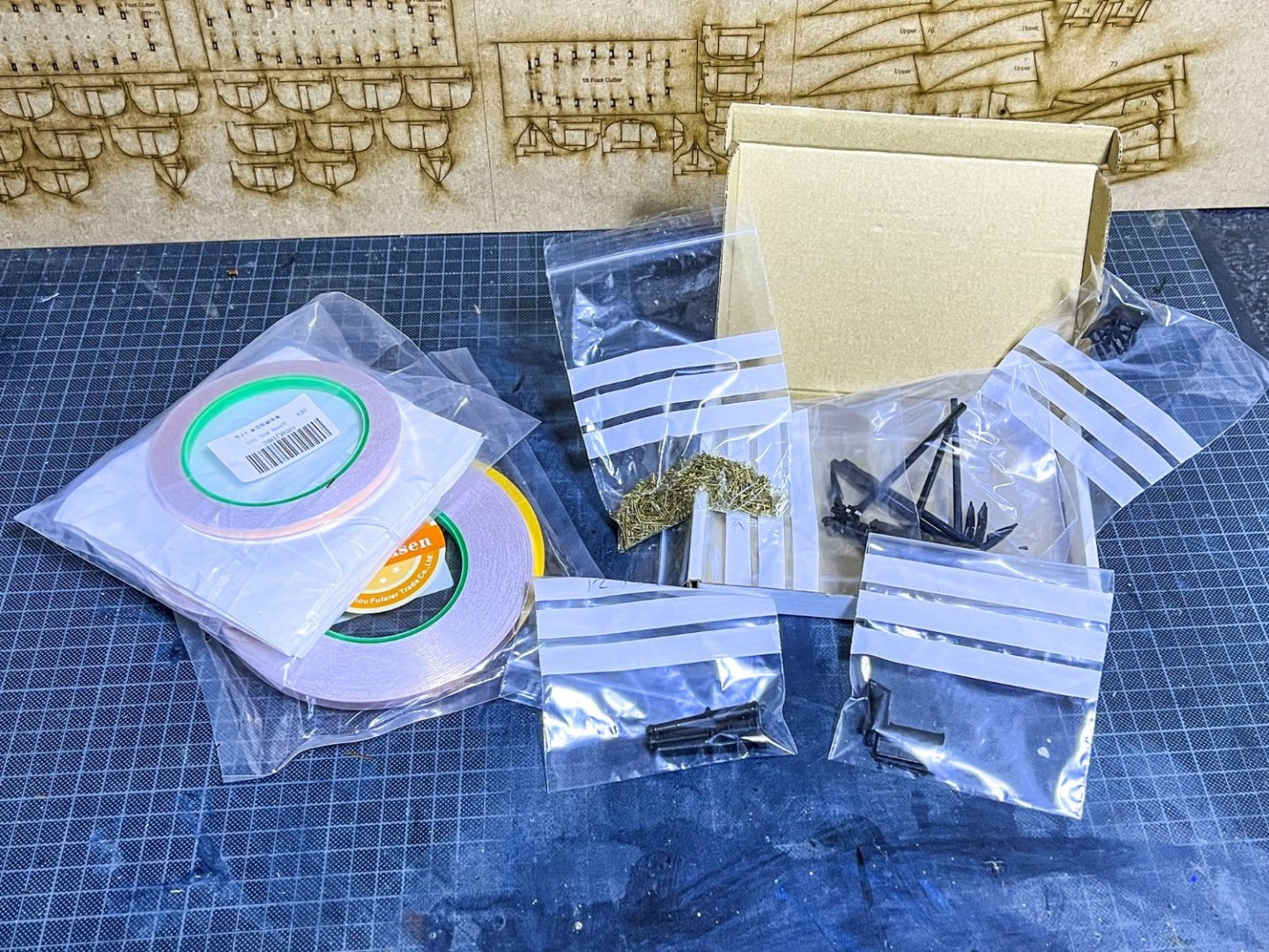
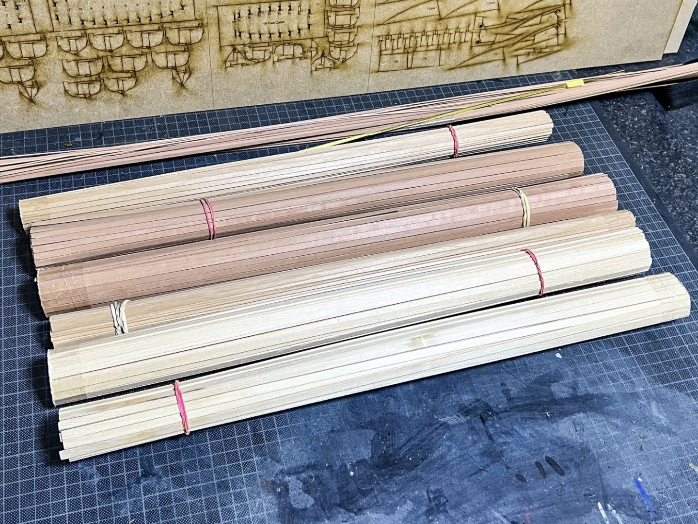
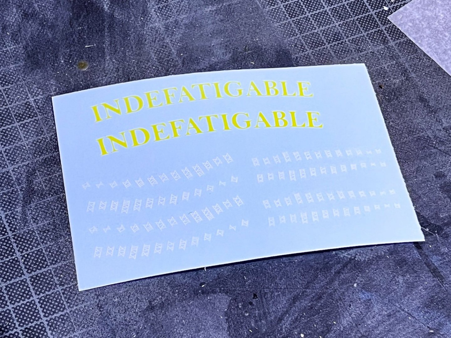
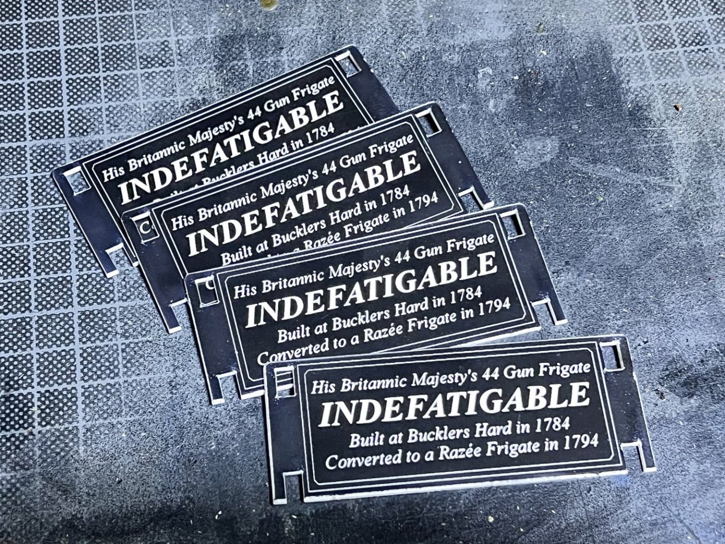
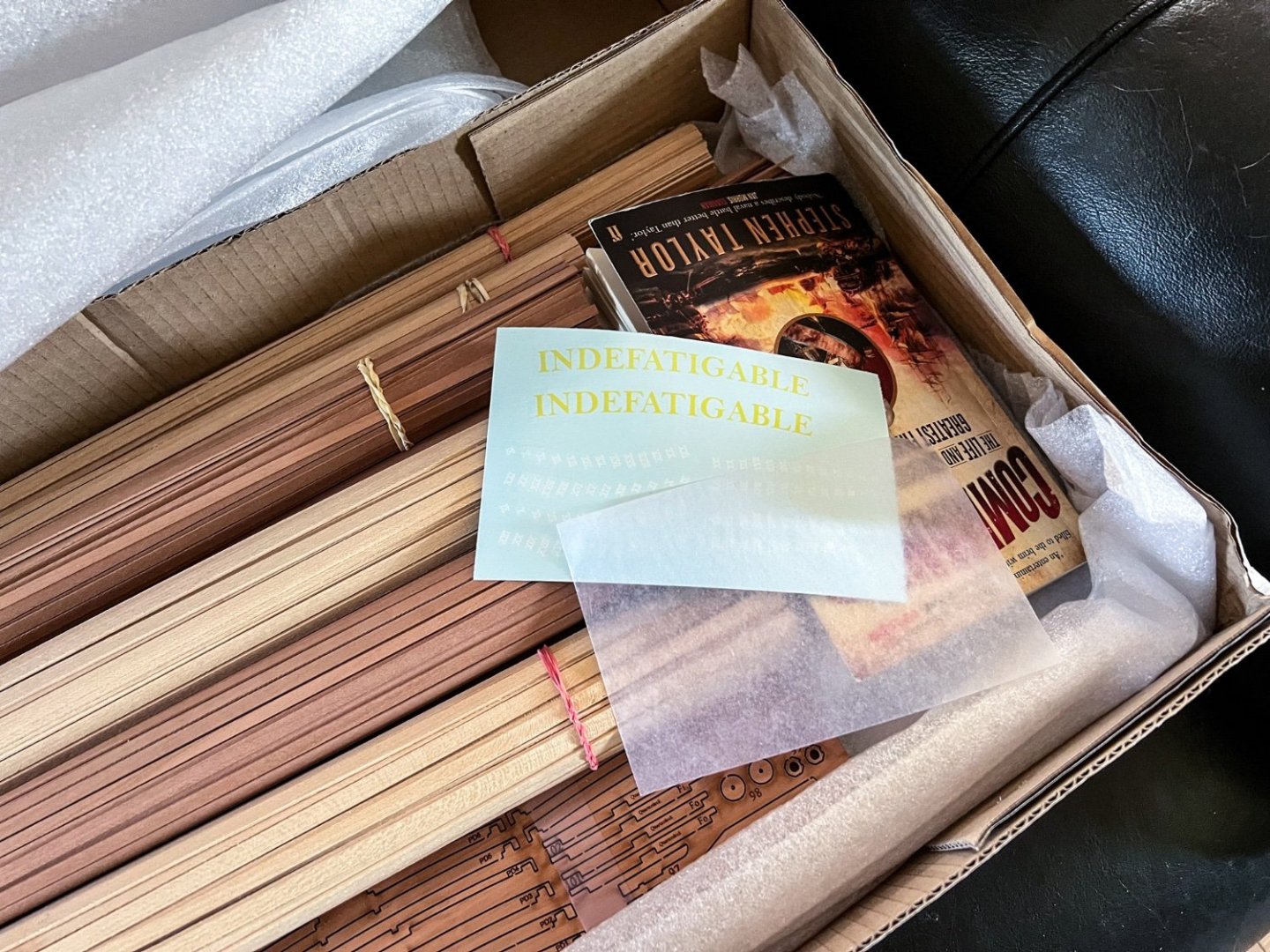
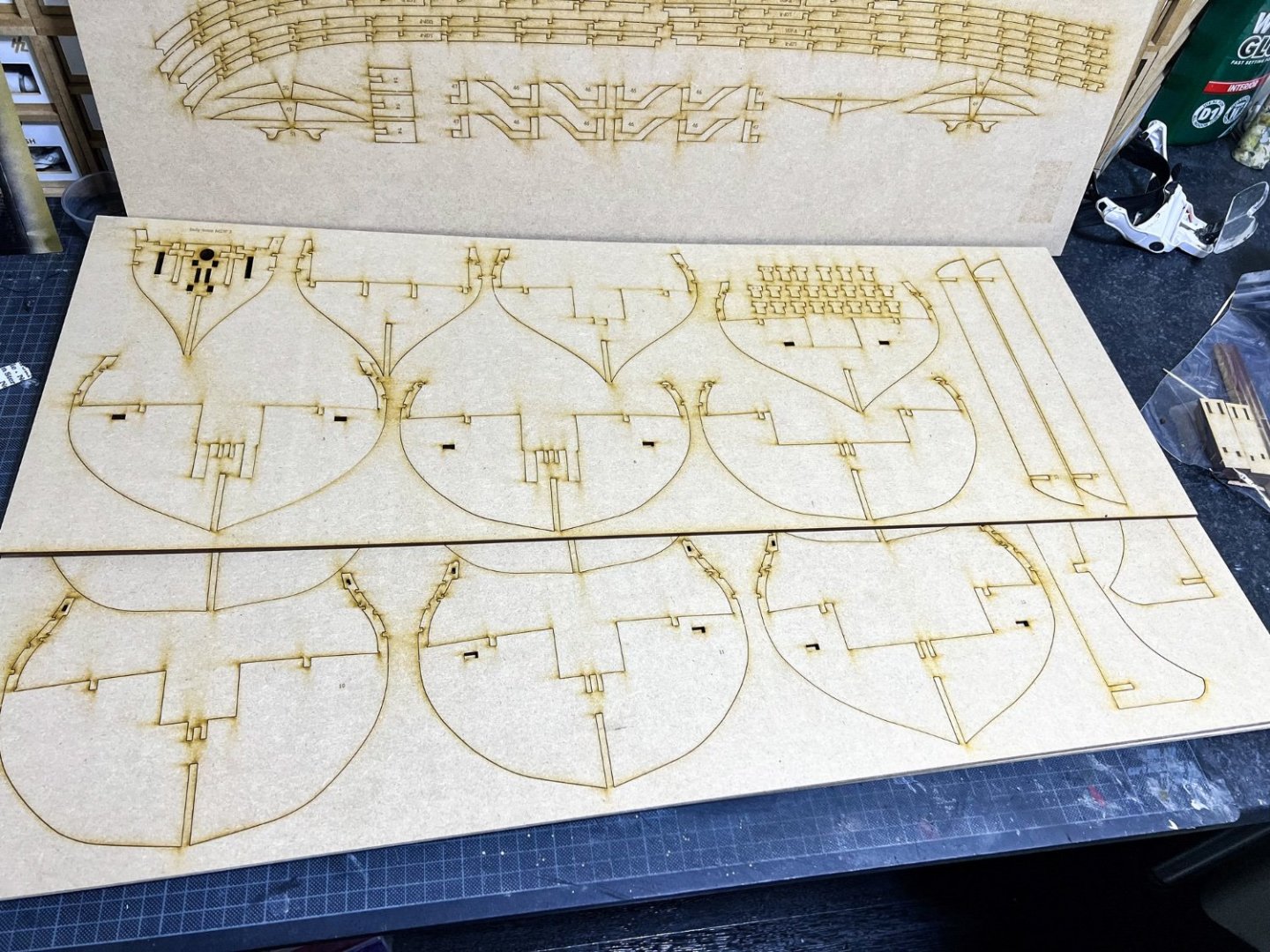
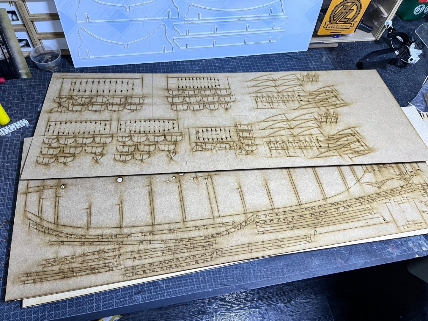
Continued. I've grouped most of these photos into thickness of sheet, and there are a lot of various thicknesses with multiple sheets for them. You can see the tabbed gun carts here too. Those tabs are on the forward 'bulkhead', closest to the inner bulwarks. You're going to have to make FIVE ship's boats for this one! Inner bulwarks are split into three sections to cover the entire length. There will also be doorways from the cabin into the quarter galleries. 3D printed stuff, like belfry, anchors etc. and I do see some copper tape there too. Quirks of prototyping. Various cabin floor sections. LOTS of strip too. Decals for name and depth markings. Also, there is no white edge on that text. It's merely the light catching the ink edging! I have checked.

- 488 replies
-
- 32
-
-
-
- Indefatigable
- Vanguard Models
- (and 1 more)
-
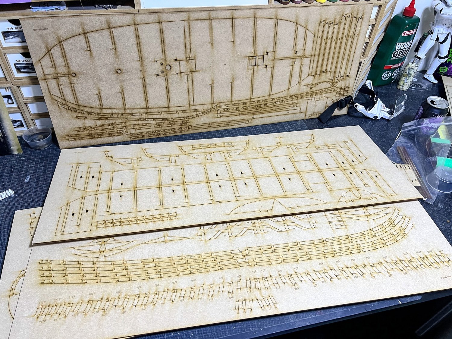
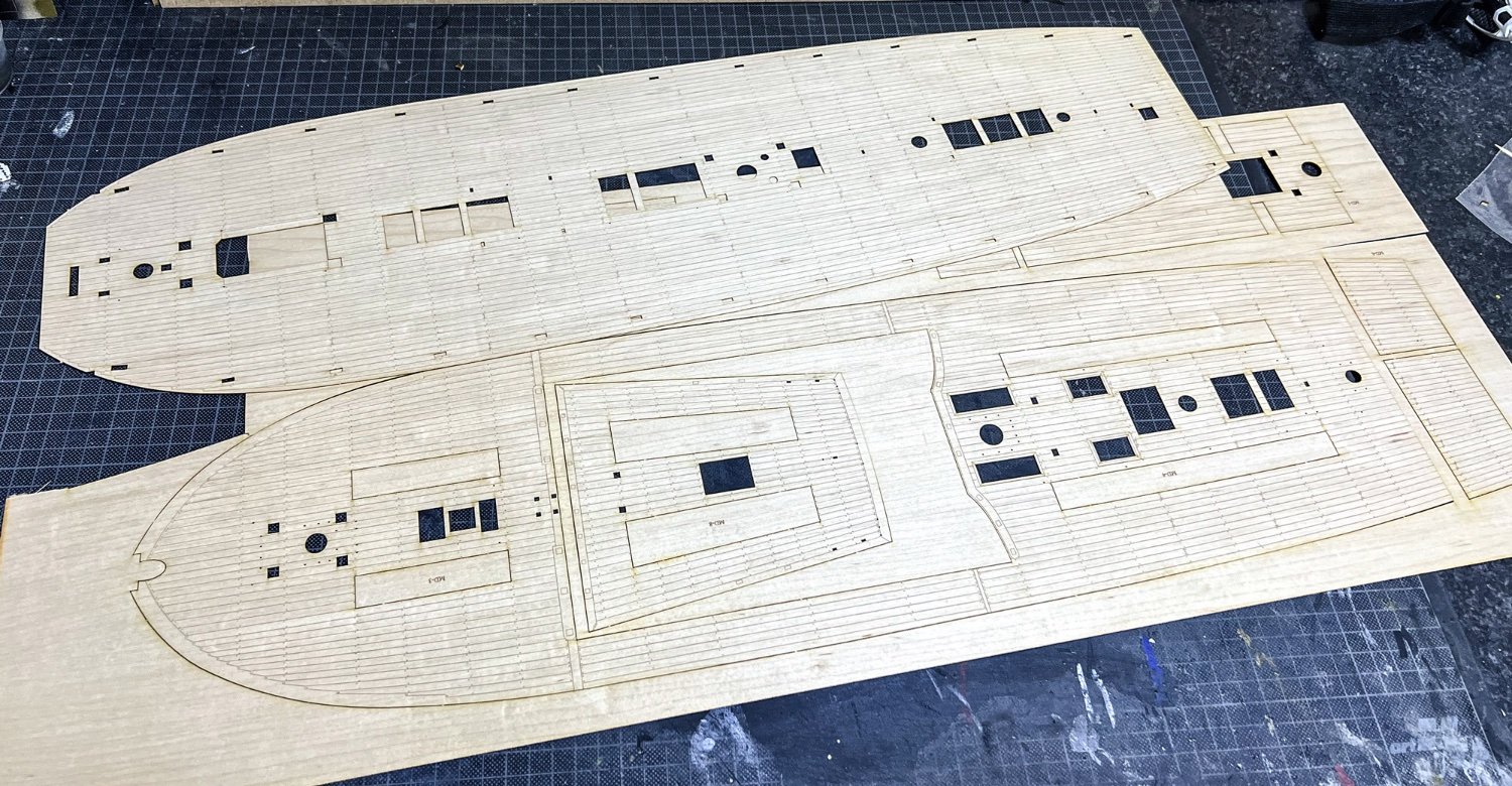
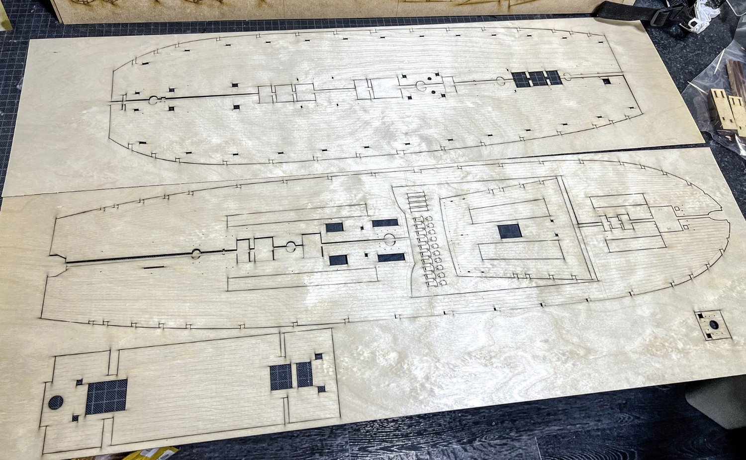
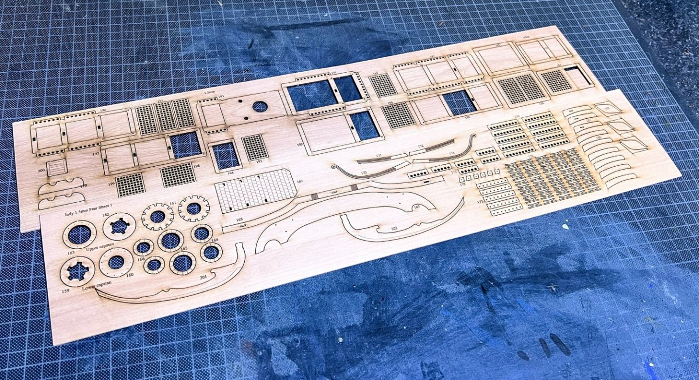
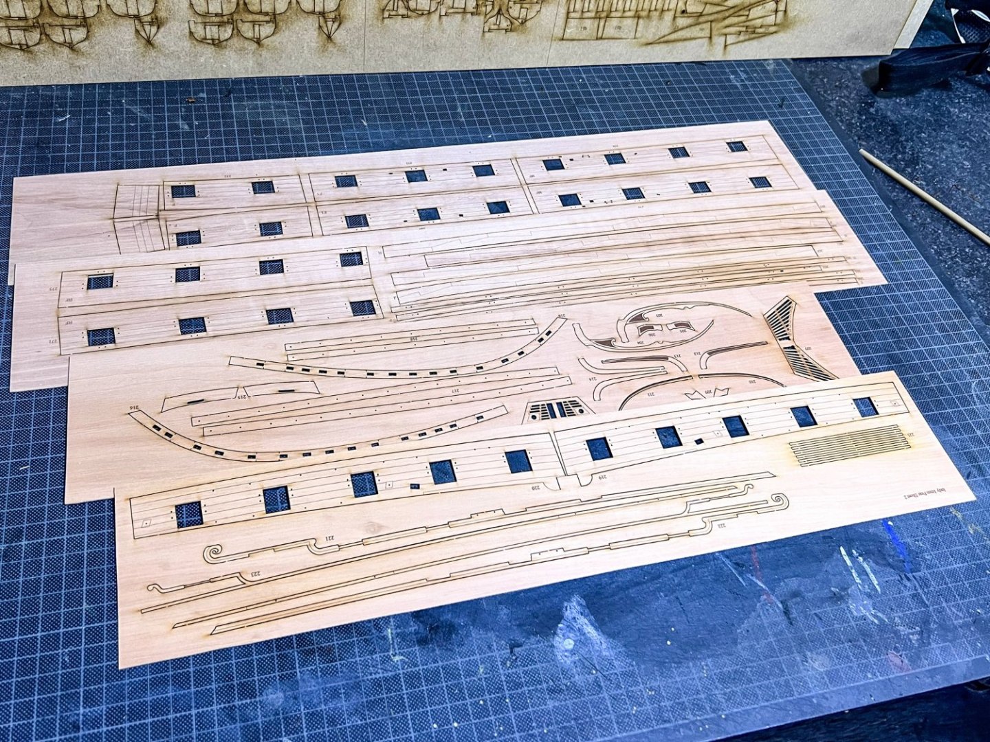
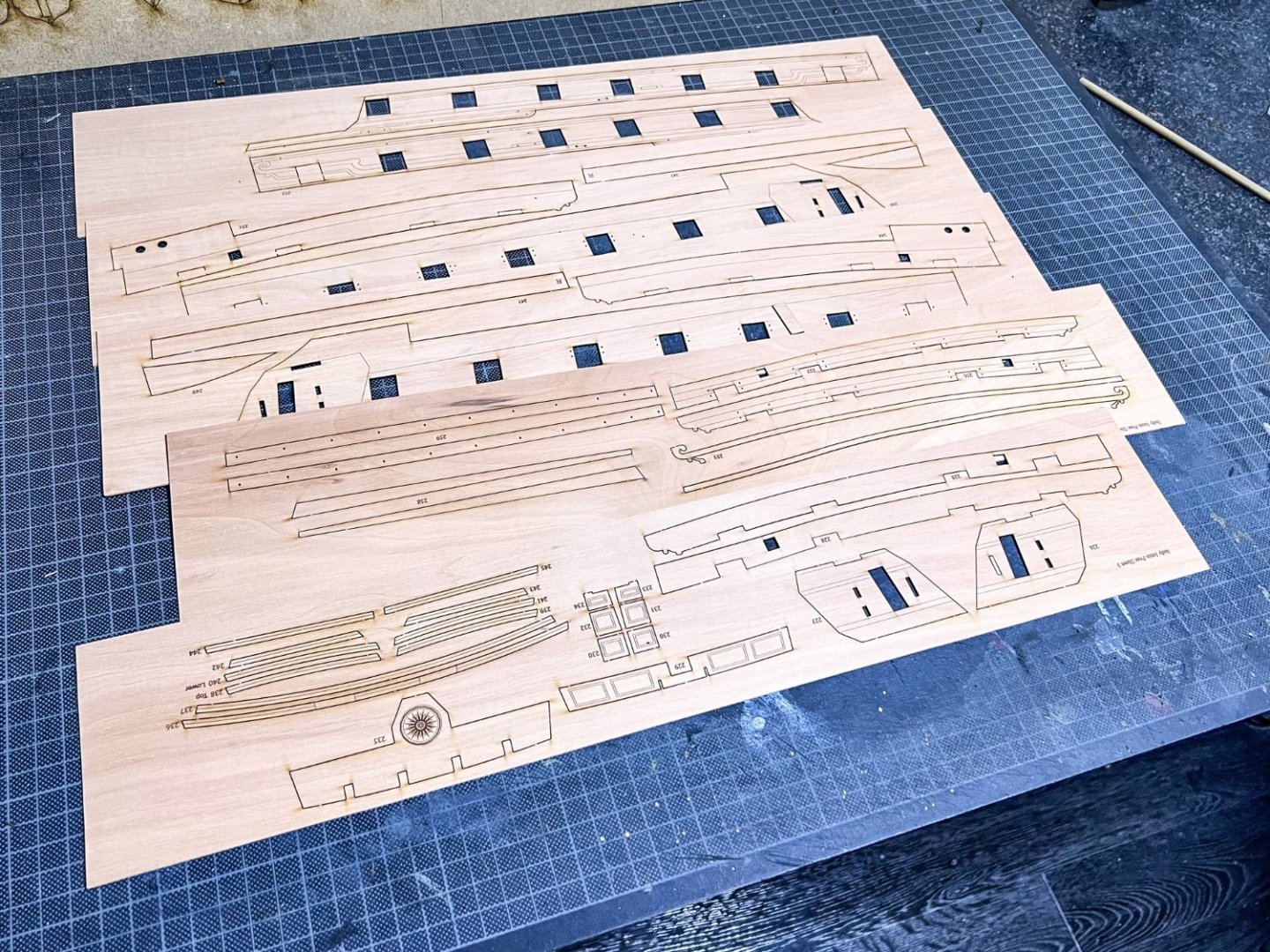
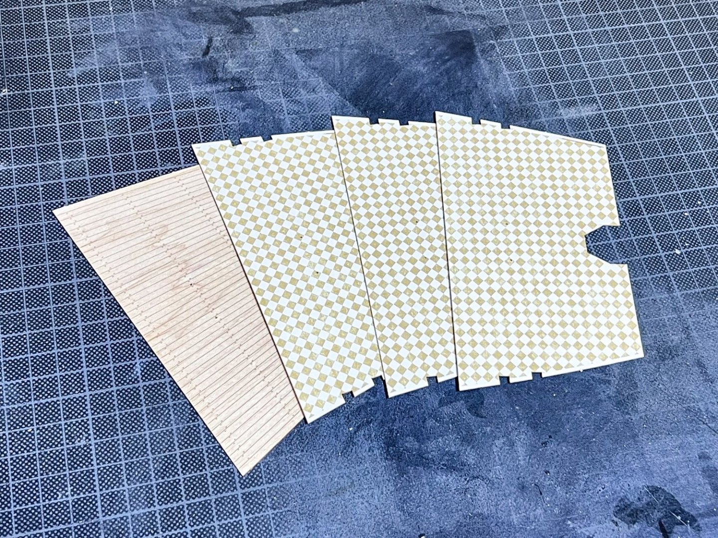
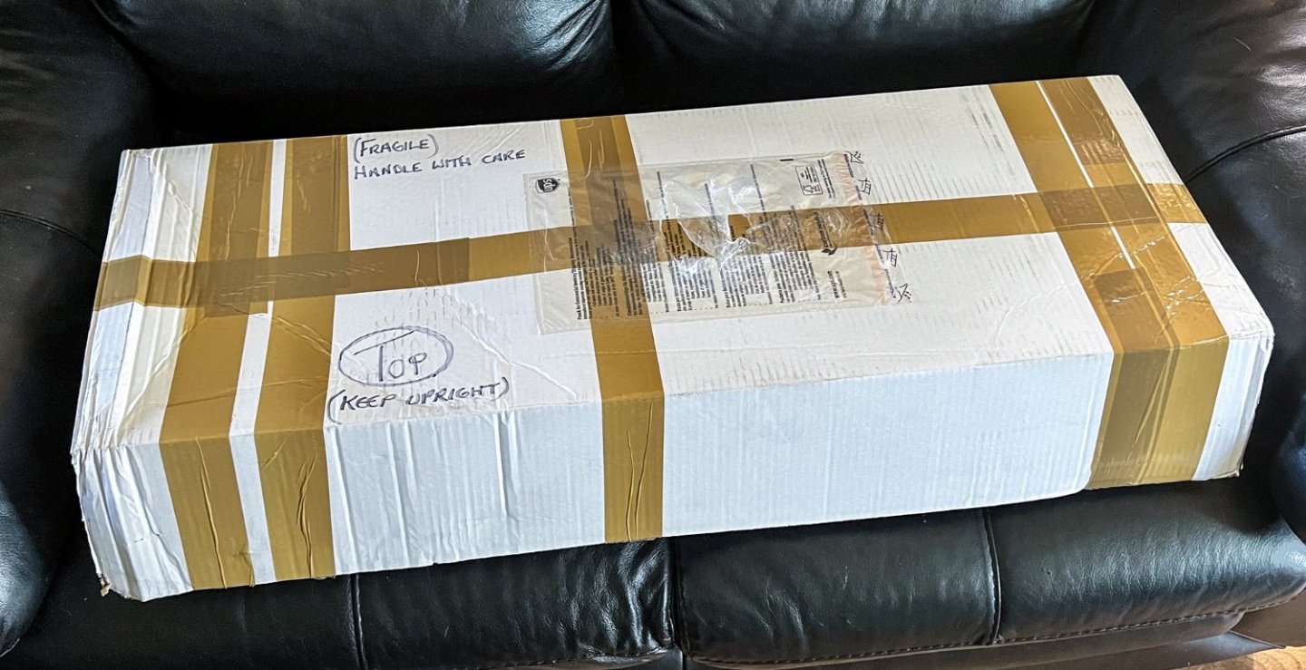
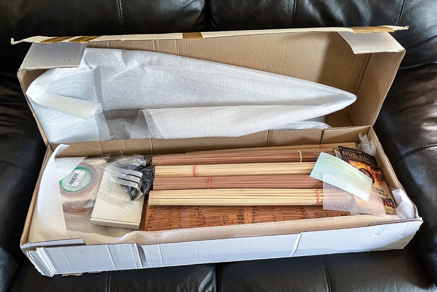
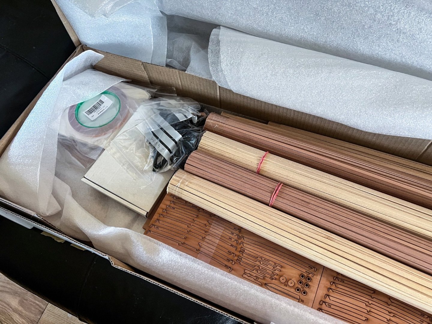
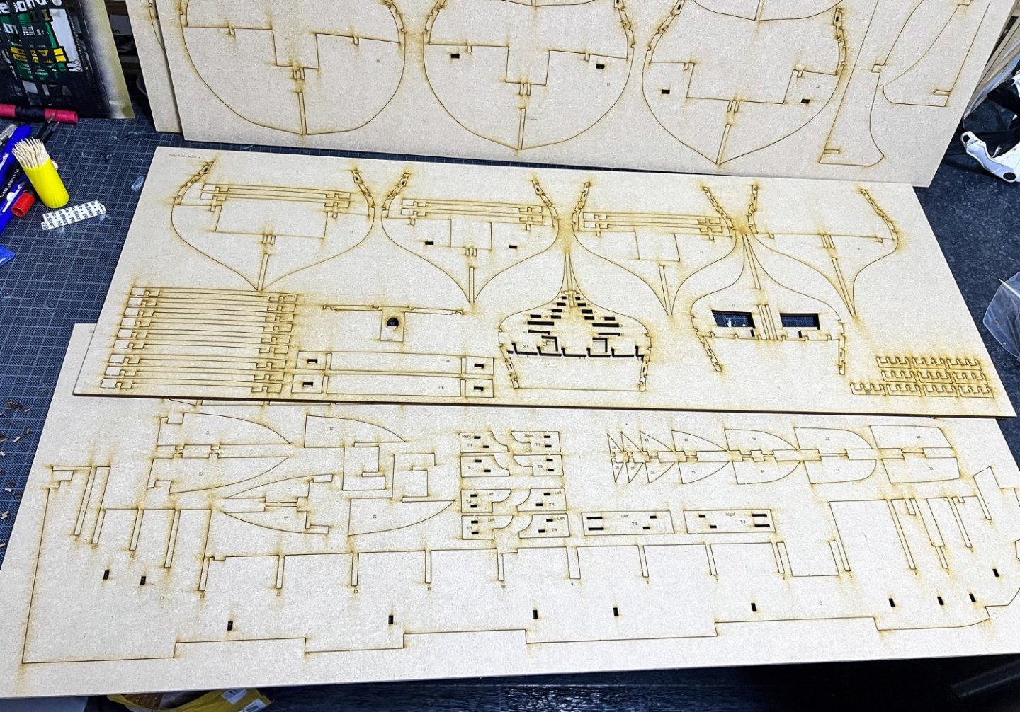
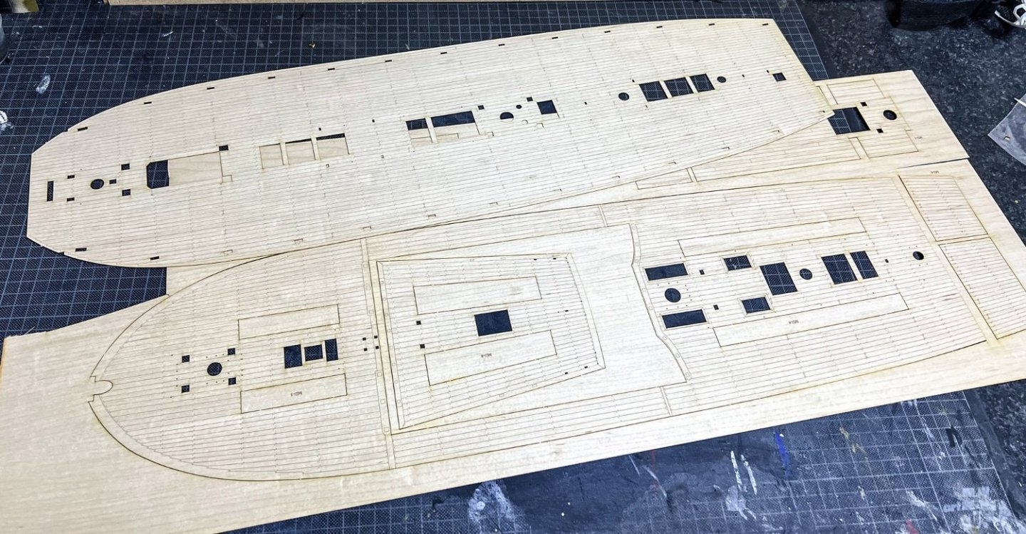
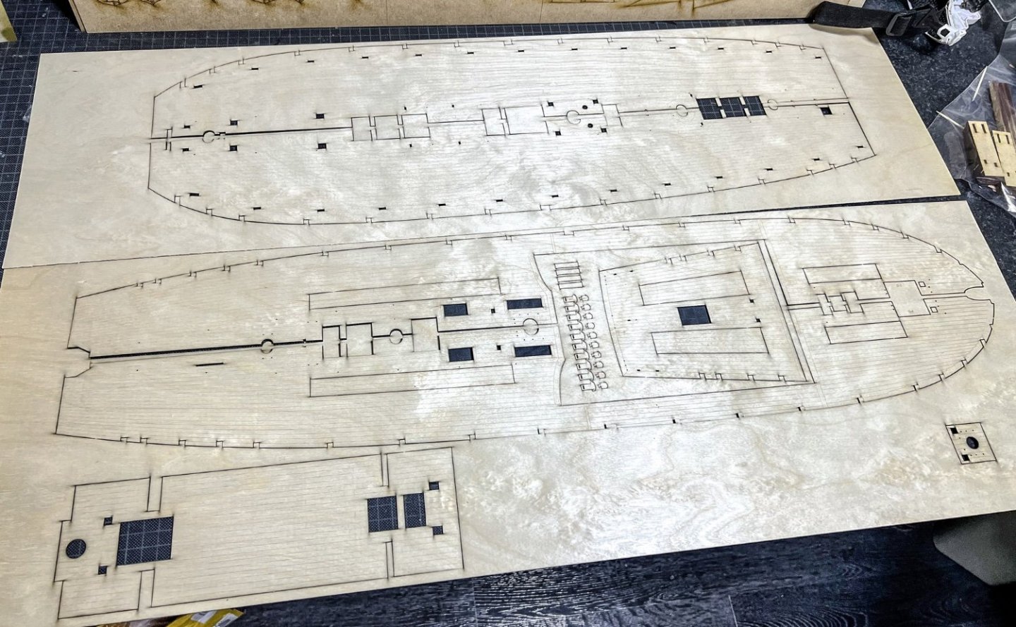
Time for a quick update. This will be the last one before work starts very shortly. I'm making this update over TWO posts due to number of pics. These are just camera photos and won't represent anything you see in the manual. Indy turned up with UPS this morning, and the box is large and heavy. In fact, the box isn't large enough yet as the masting, rigging, manual and plans also need to be included, as well as PE etc. The box was packed out as it was. This one took up two seats on my sofa. Take a look through and you'll notice some little things here and there. One of those is that the main gun deck carriages are tabbed so they slot into the deck and can't be knocked free later in the build. This is only an optional feature as the modeller can, if they wish, plank over the tab slots and remove the tab from the carriage. That would be up to the individual but this is a perfectly good solution that will be invisible when implemented. If also means the guns will be perfectly spaced too and the barrels therefore evenly protrude from the hull. Those barrels will also be fitted after the hull is painted, so attaching them later won't dislodge a gun cart. This is the engraved maple deck which won't be included as standard, unlike the other kits. This kit will have traditional planks for the deck, but it is quite likely that this option will be provided on release. If that happens, then the gun carriage location slots aren't likely to be there, and you'll simply open them up if you want use that kit feature. Oh, these parts are BIG!! My cutting mat is in 1cm squares, as a guide. Not fantastically clear here, but the ply sub decks are engraved with planks. This isn't the finish. It's designed to give you a template onto which to lay the kit planks. That will save the modeller having to mark up stuff themselves.

- 488 replies
-
- 35
-
-
-
- Indefatigable
- Vanguard Models
- (and 1 more)
-
Questions Before I Buy My First Ship
James H replied to Magarkus's topic in New member Introductions
I don't really use much in the way of tools for what I do. To build VM prototype kits, I use: Scalpel knife sanding block and sandpaper tweezers steel rule clamps - 2inch and 4inch nail pusher pin vice with selection of drills long nose pliers needle files waterline marker I do have a plank nipper for occasional stuff, but really use it. They are cheap enough though. Most of what you see there is very basic and quite inexpensive. -
lol! I really don't think that's the remit of any kit! I've certainly never, ever seen that from any manufacturer.
- 476 replies
-
- 5
-
-
-
- sphinx
- vanguard models
- (and 1 more)
-
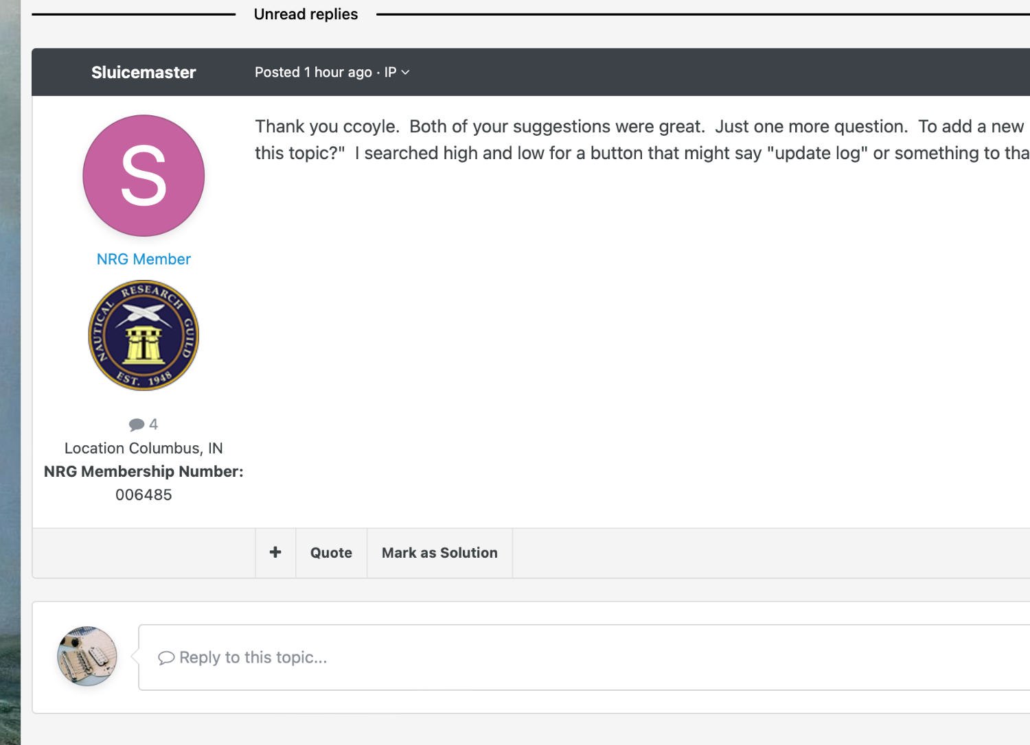
Updating Build Log
James H replied to Sluicemaster's topic in Using the MSW forum - **NO MODELING CONTENT IN THIS SUB-FORUM**
Just click the 'Reply to this topic' you see in this screenshot in the same way you replied to this topic you created. That applies throughout the site.