James H
-
Posts
5,978 -
Joined
-
Last visited
Content Type
Profiles
Forums
Gallery
Events
Everything posted by James H
-

Mantua "blue painted" photo-etched brass
James H replied to Alexisgm97's topic in Metal Work, Soldering and Metal Fittings
Pretty sure the blue areas are the remaining photo-resist film from production (from my old days in circuit board manufacture). That should be easy to gently sand away, or even peel, depending on thee type of resist (ink or film). When I built this model, I painted blue (I think) in the bare brass areas, then rubbed the parts over some very fine grade abrasive paper to reveal the brass, and then rubbed over finer papers until it was polished. I then sealed the brass with lacquer so it didn't tarnish. -
I think I'll definitely do the cannon this week. That's the most numerous of the deck furniture to build.
- 355 replies
-
- 7
-

-
- vanguard models
- Sphinx
- (and 1 more)
-
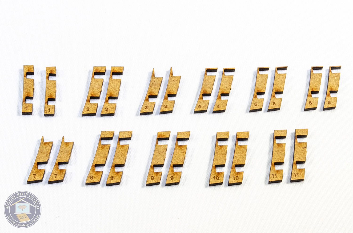
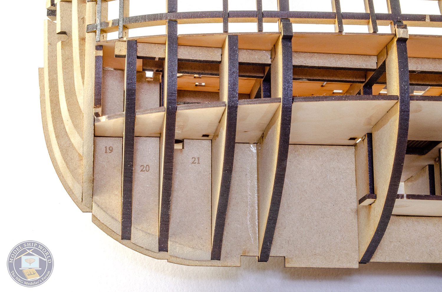
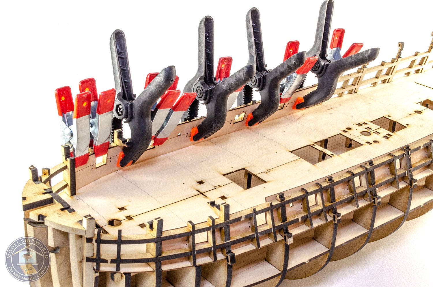
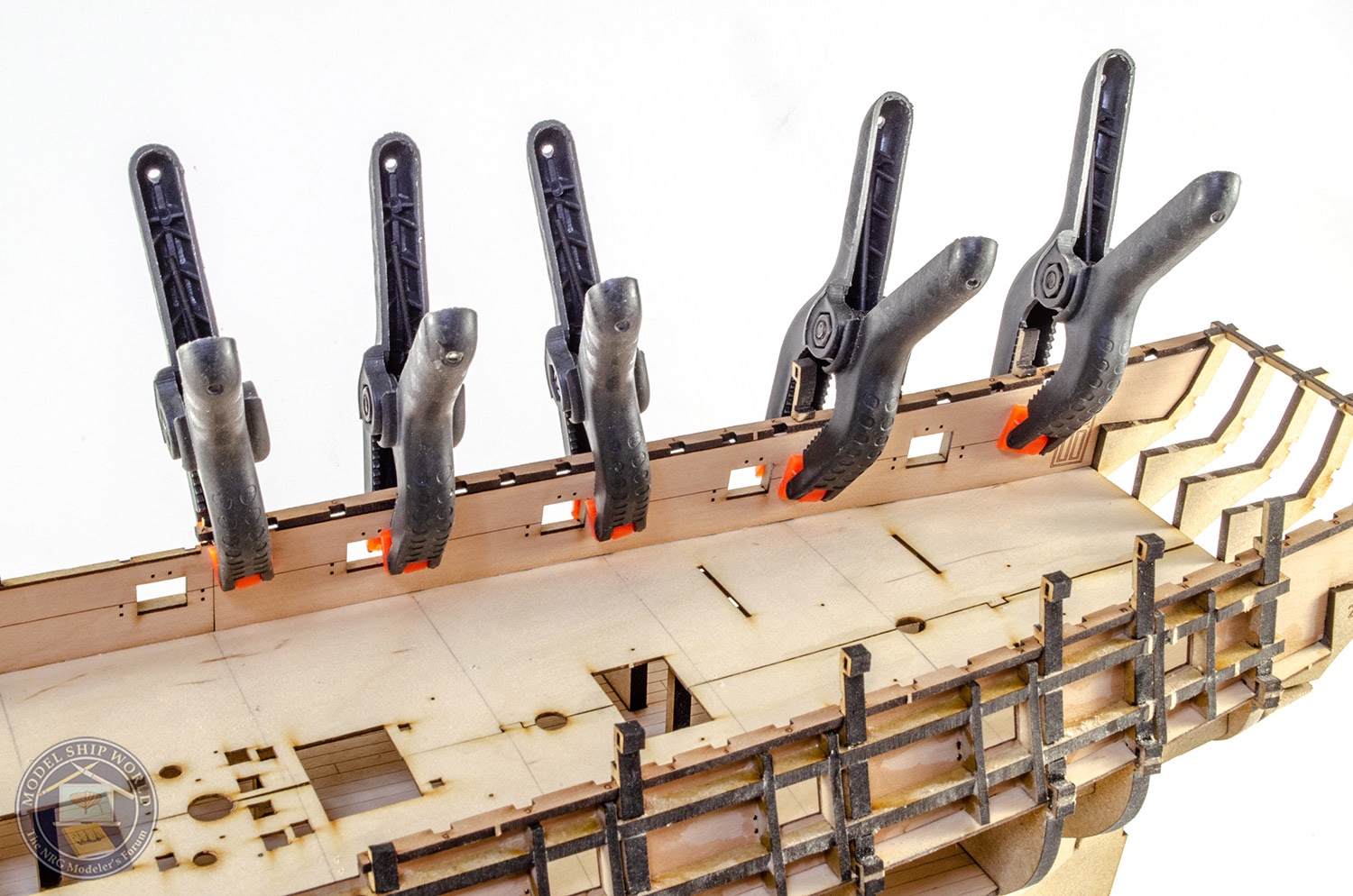
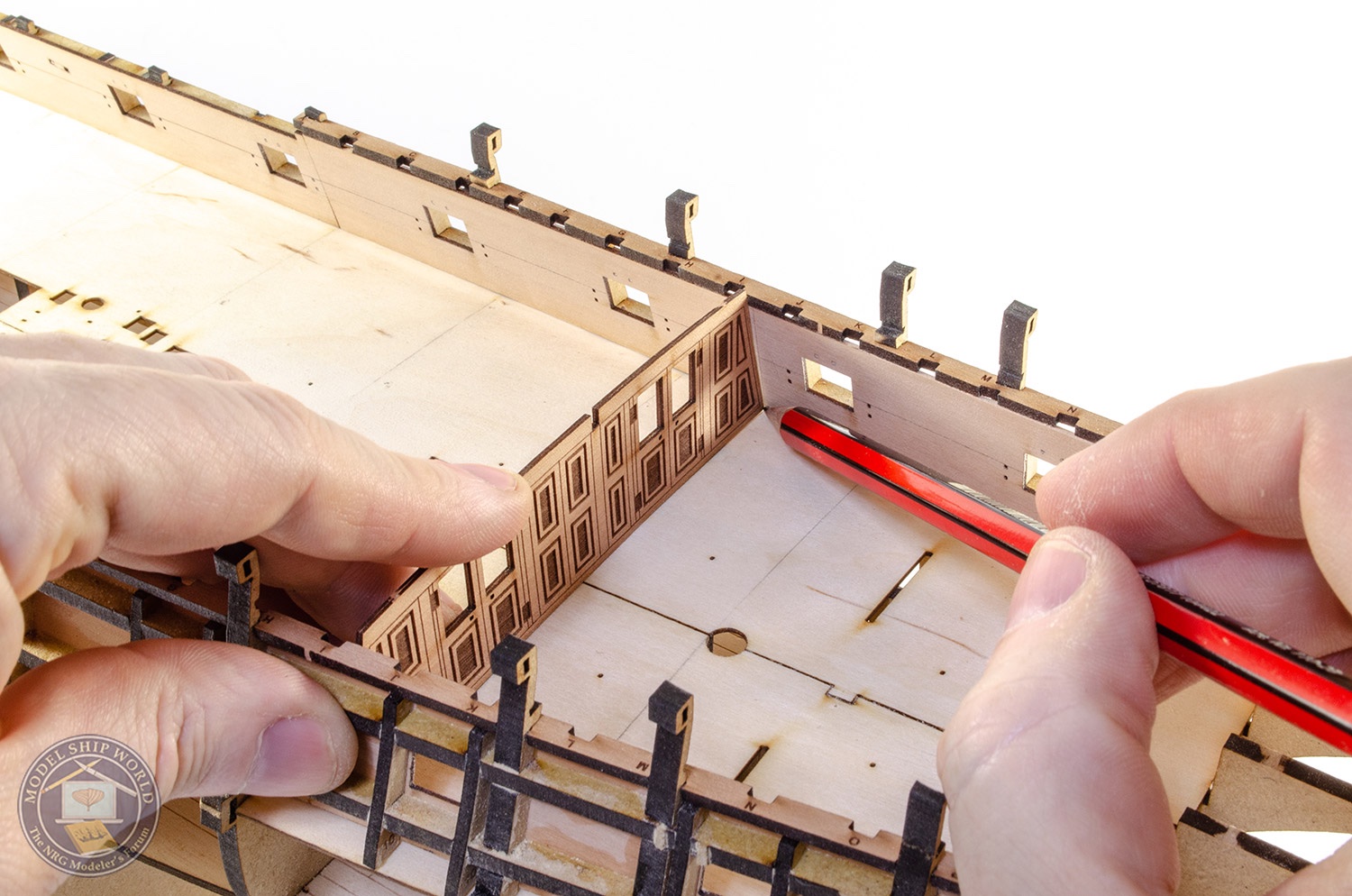
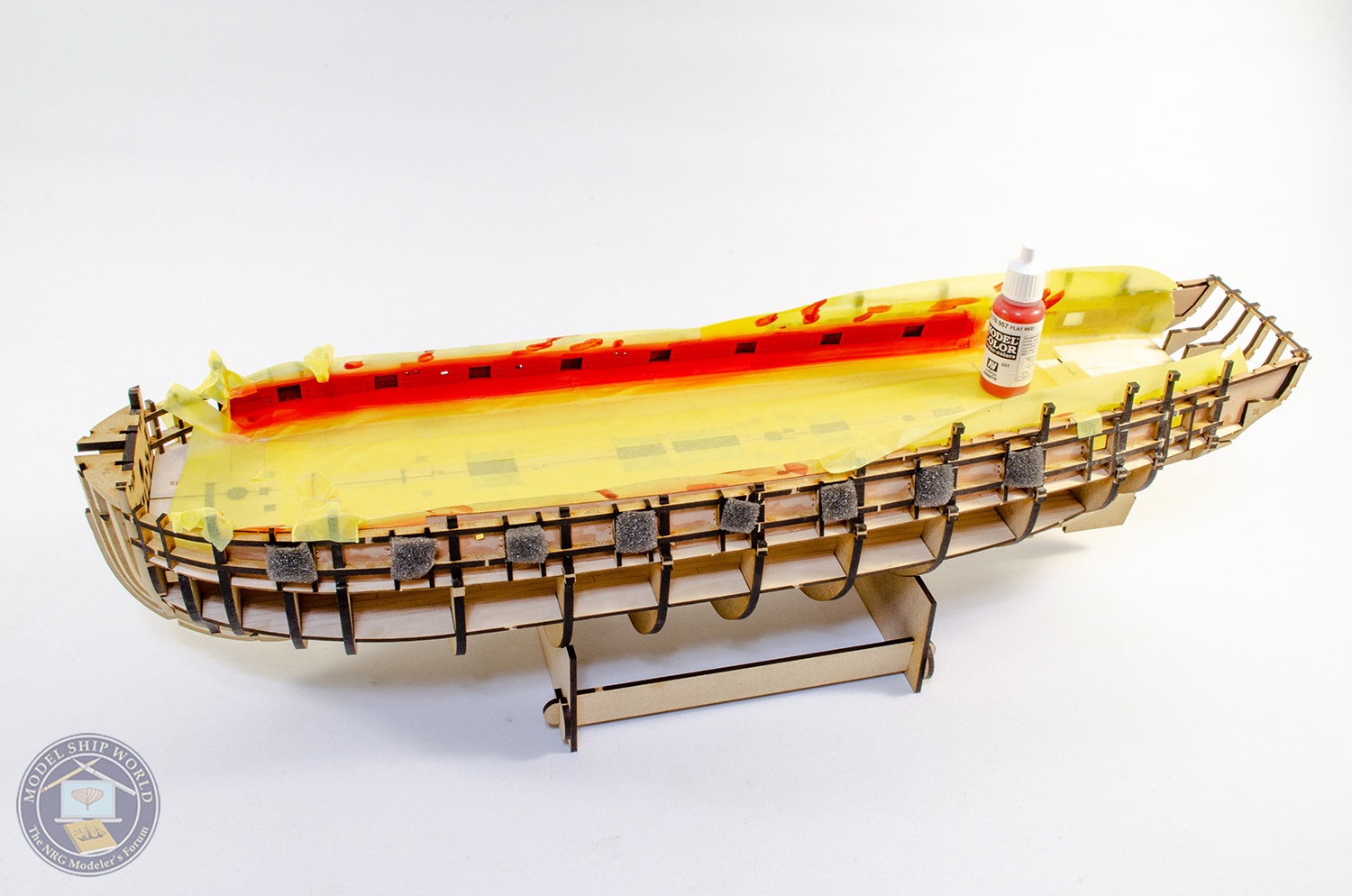
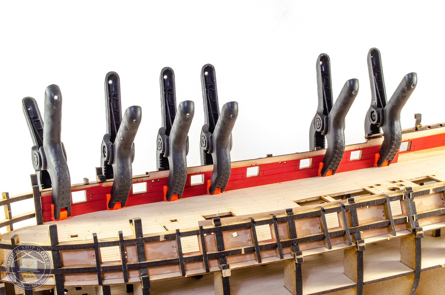
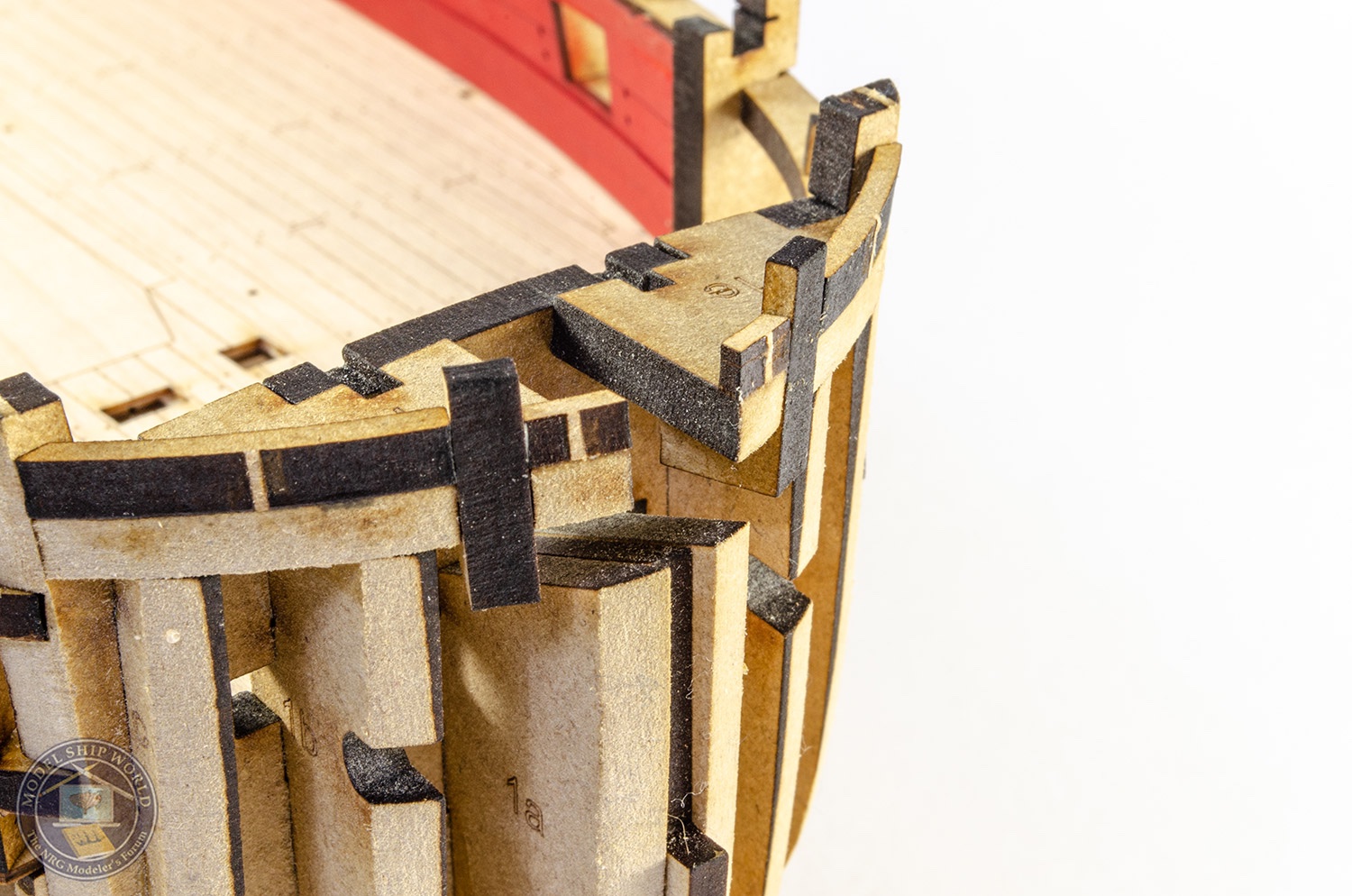
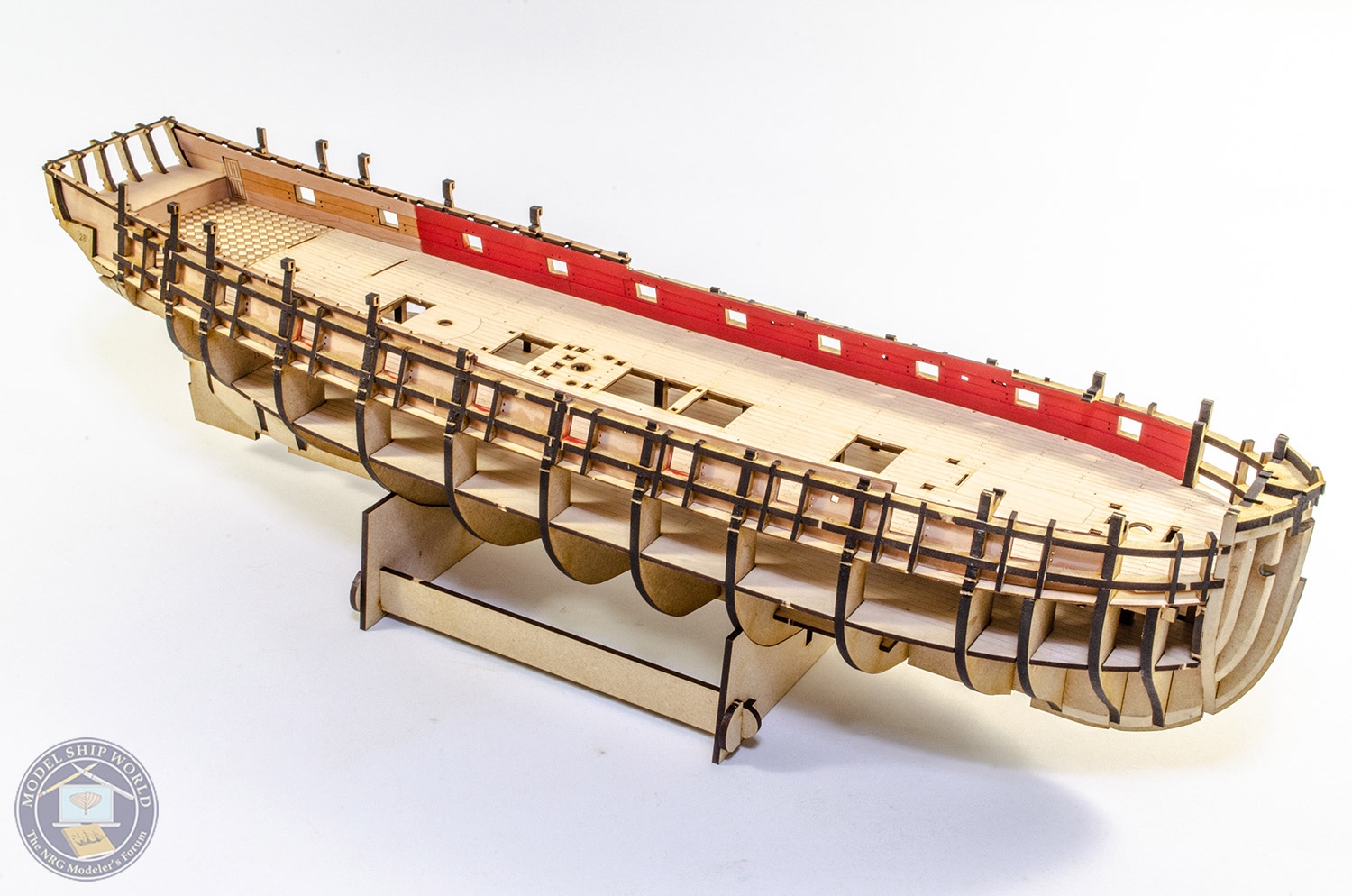
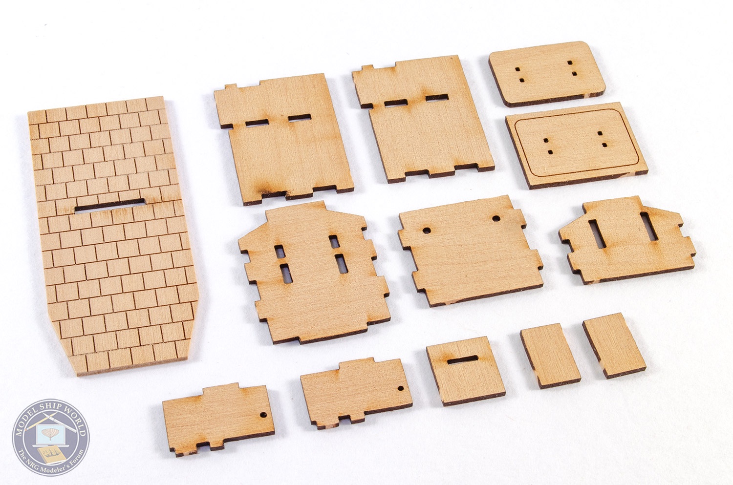
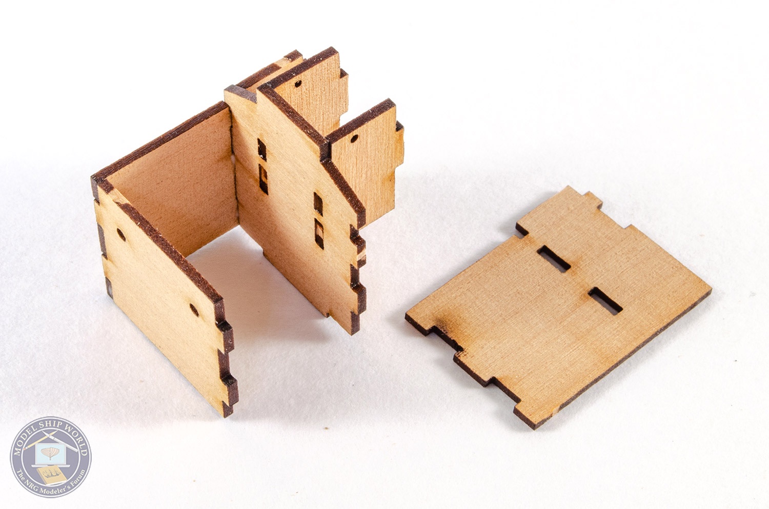
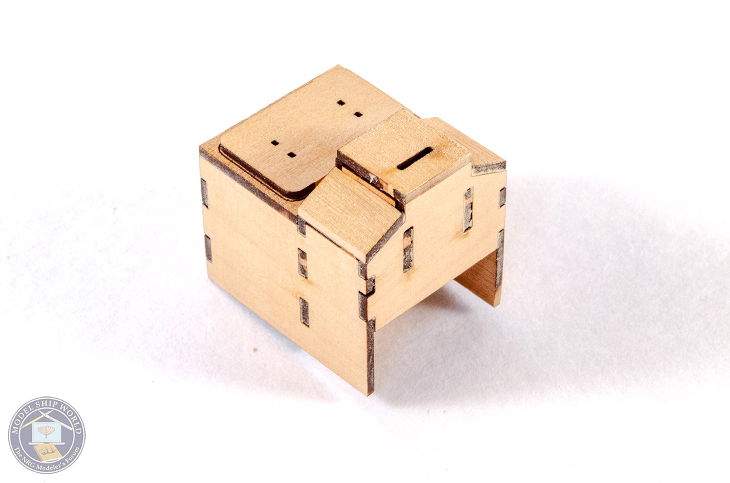
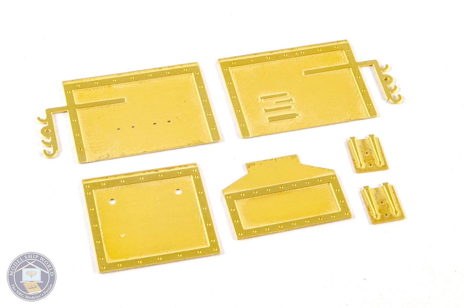
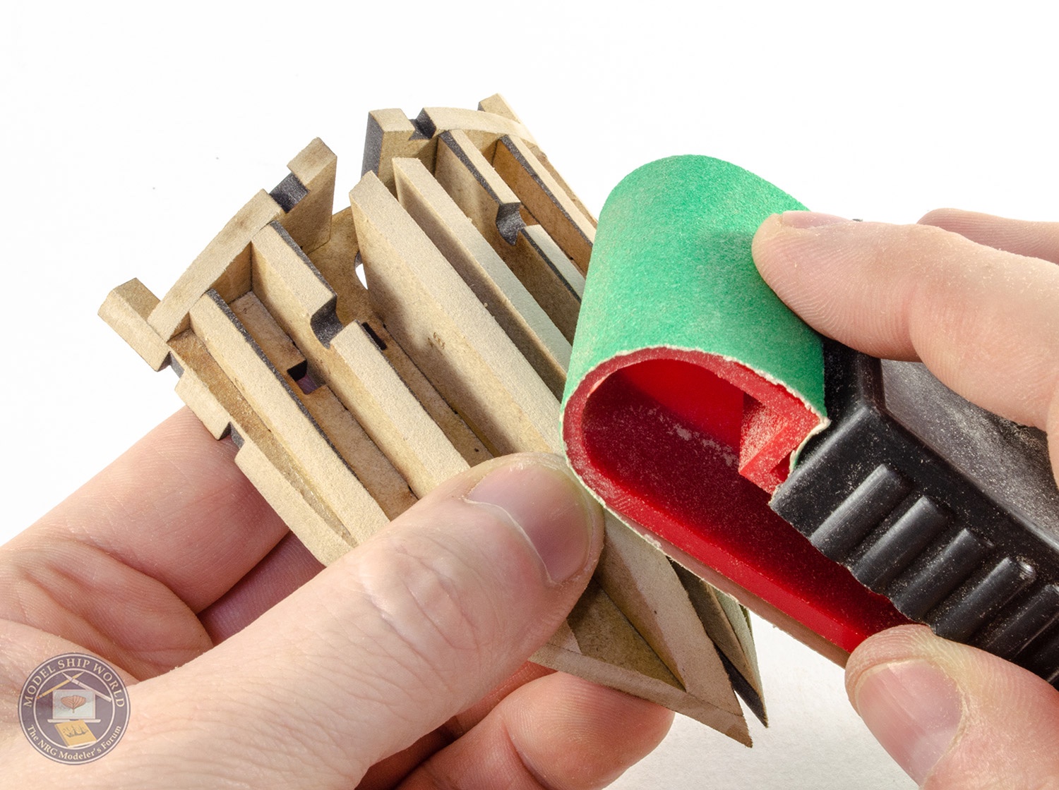
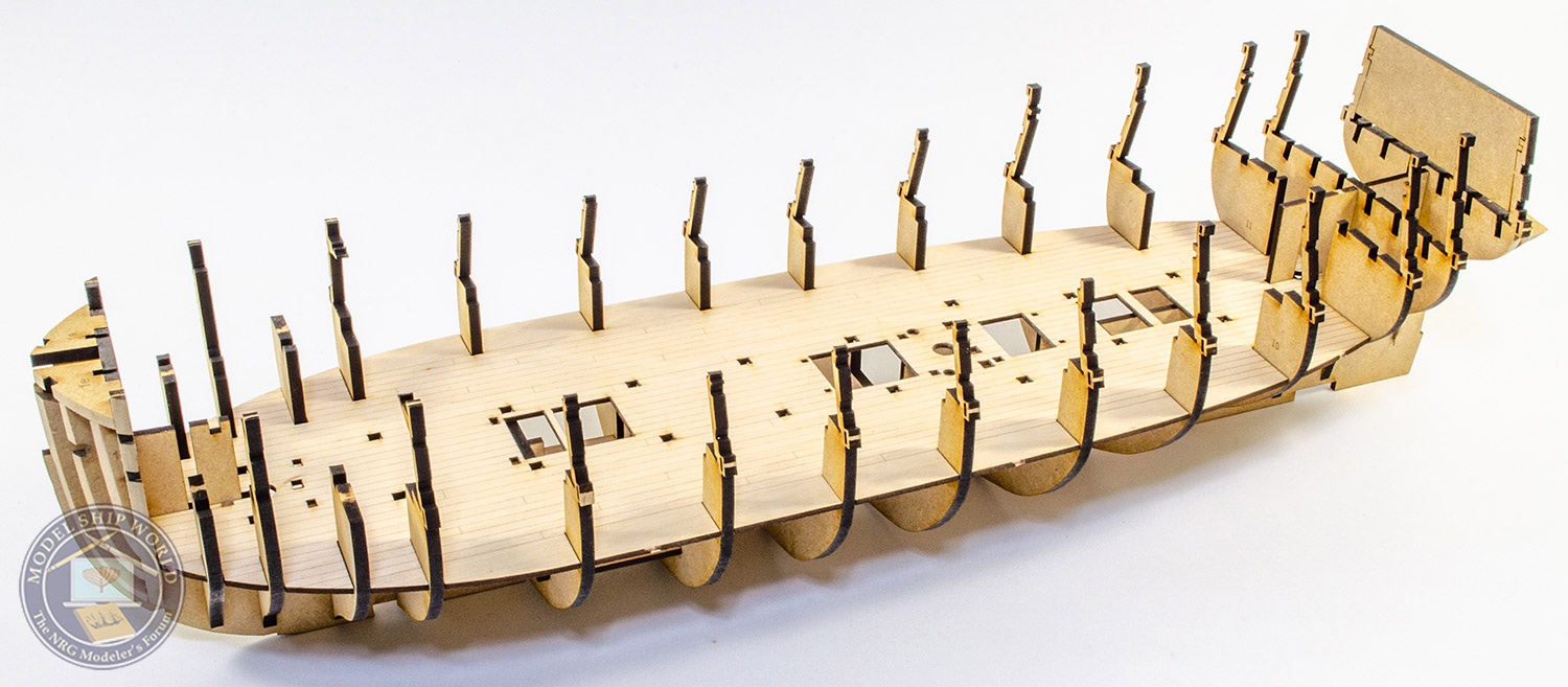
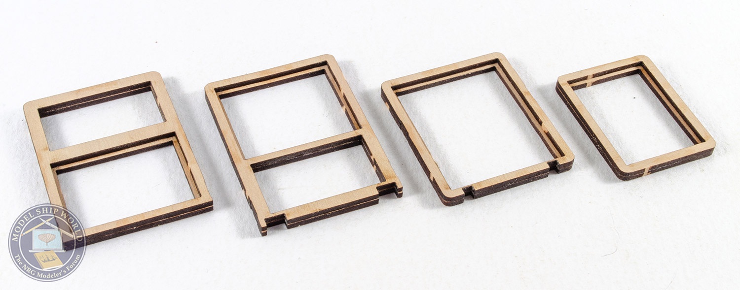
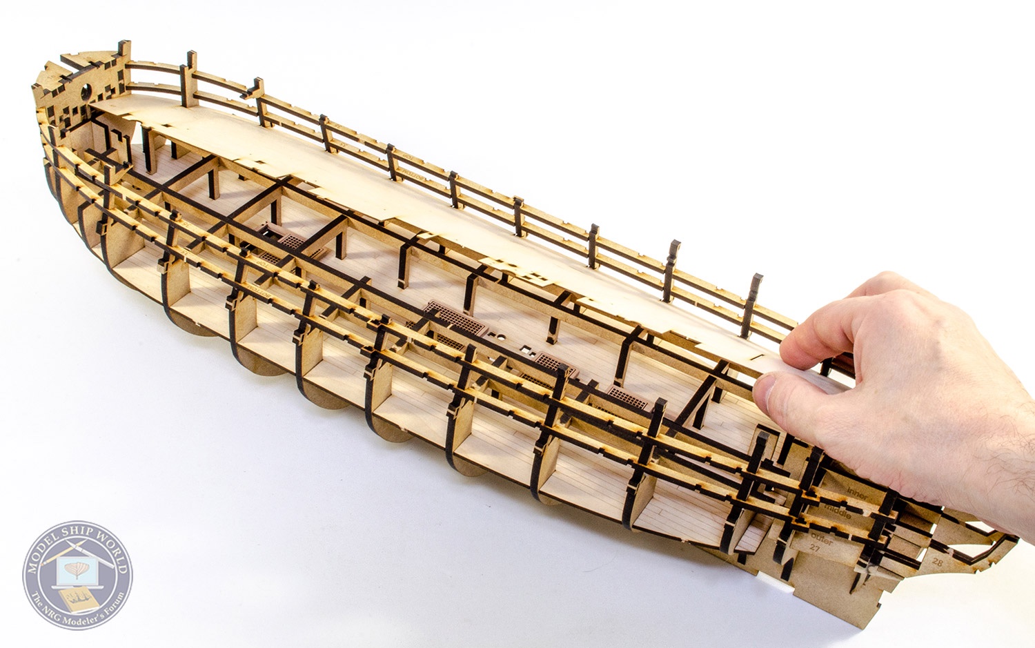
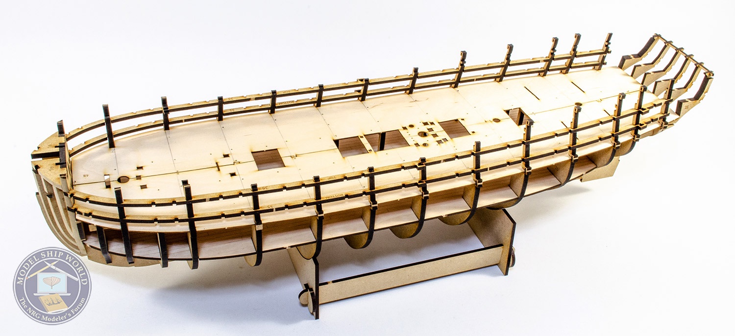
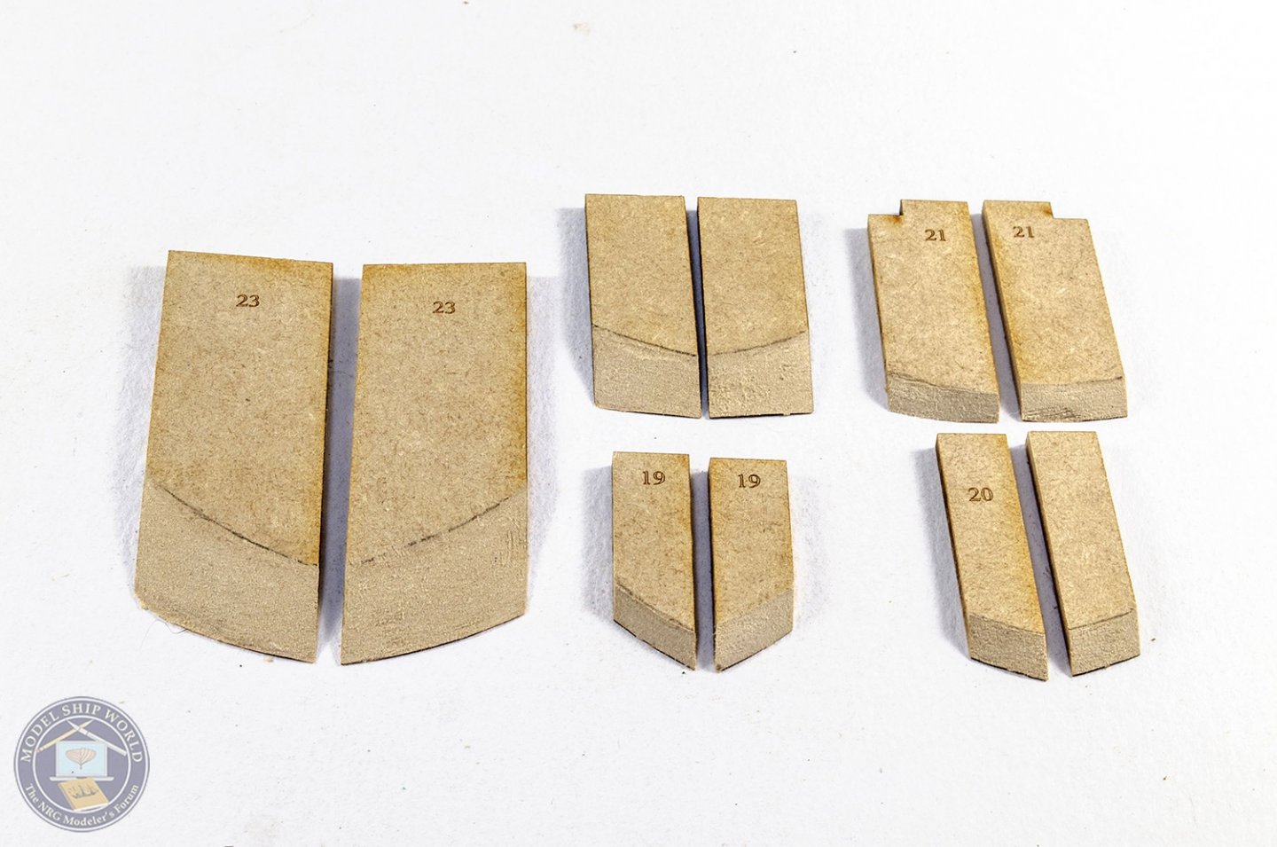
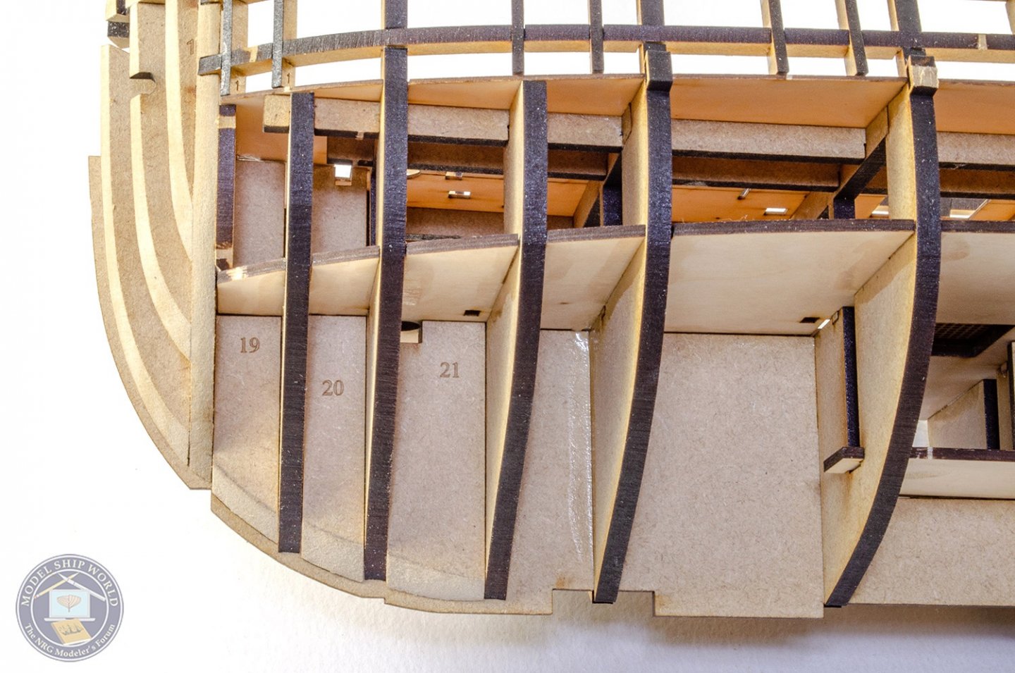
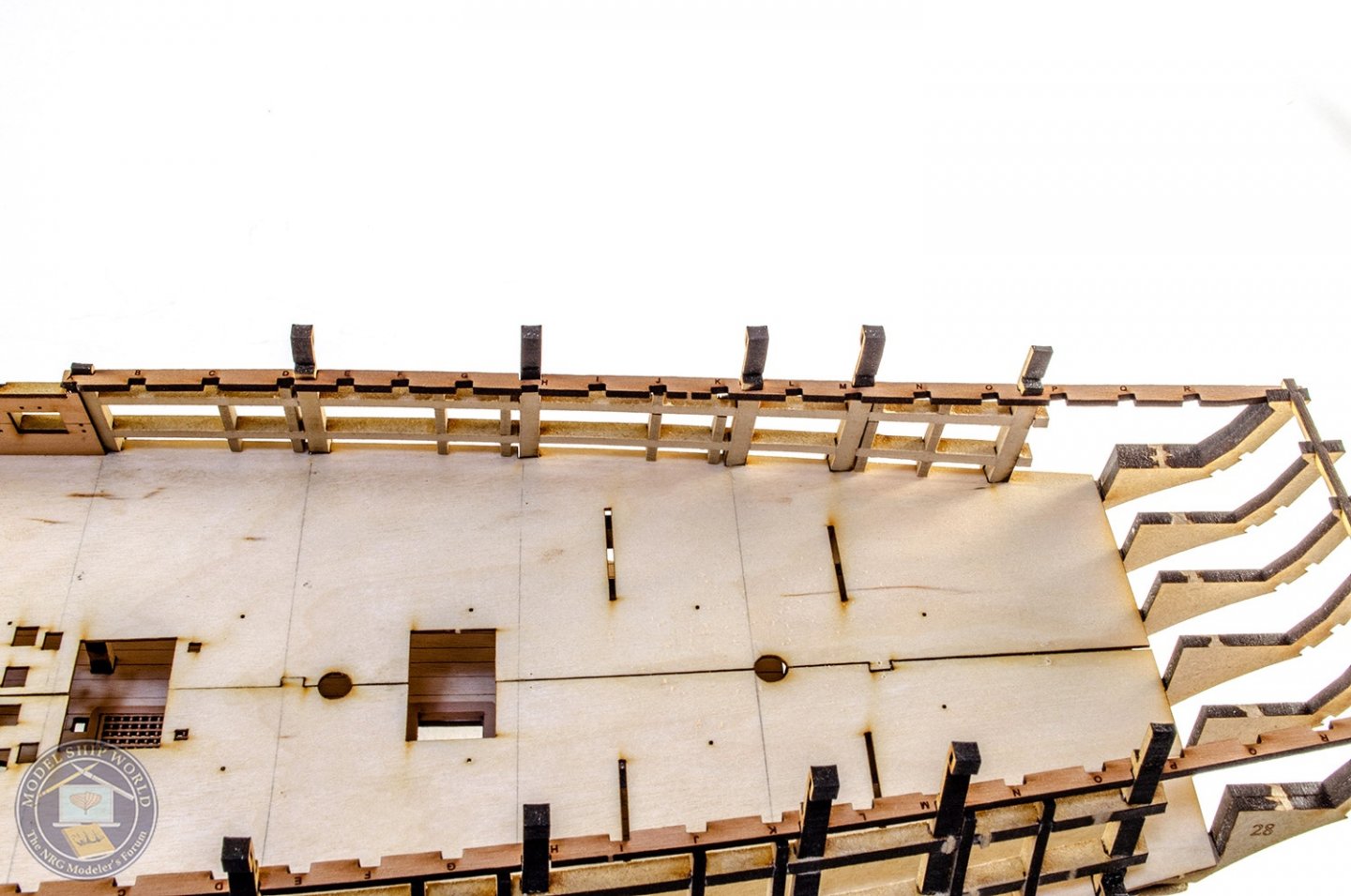
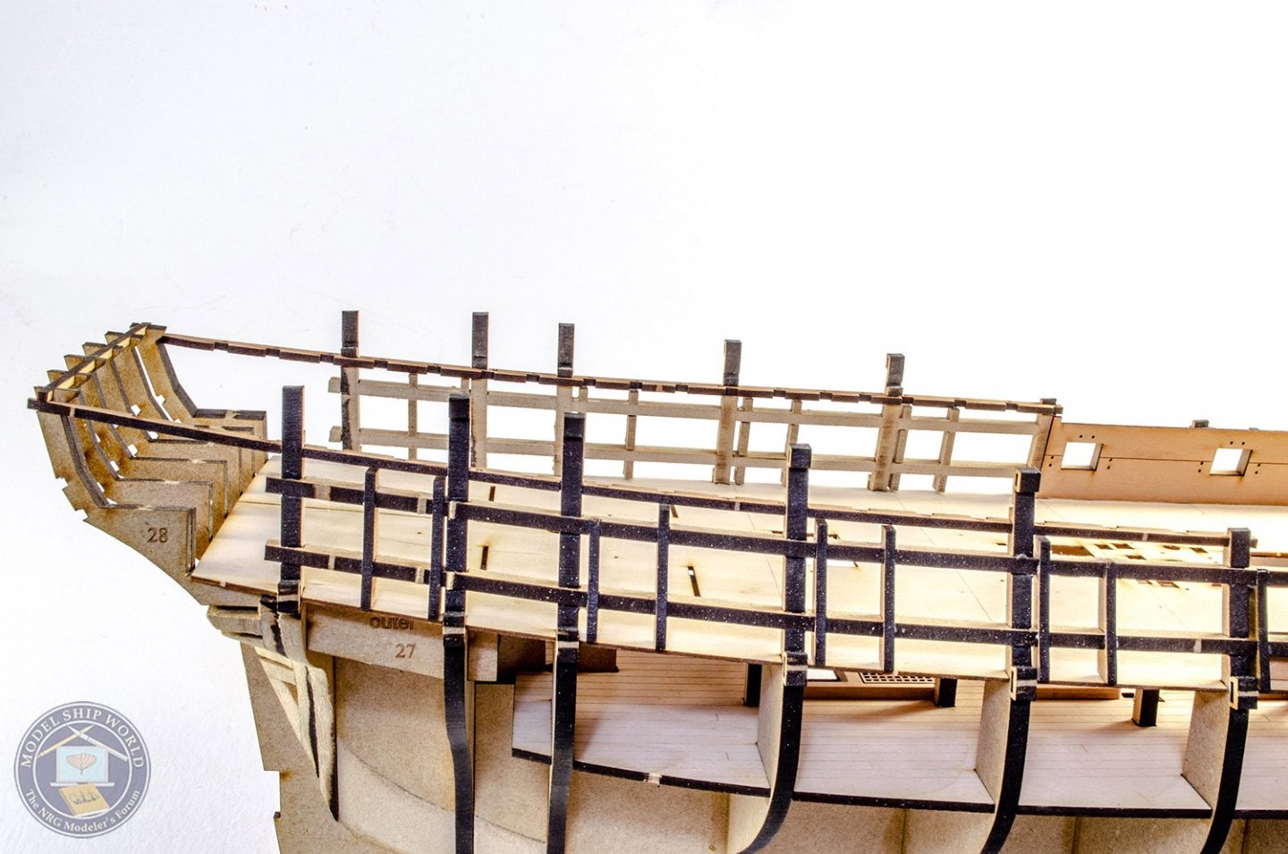
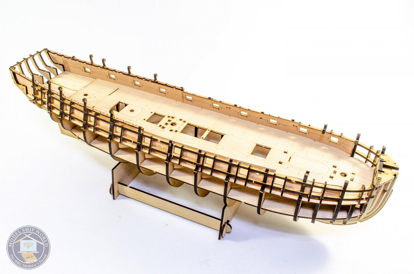
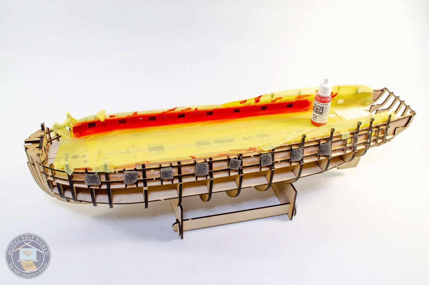
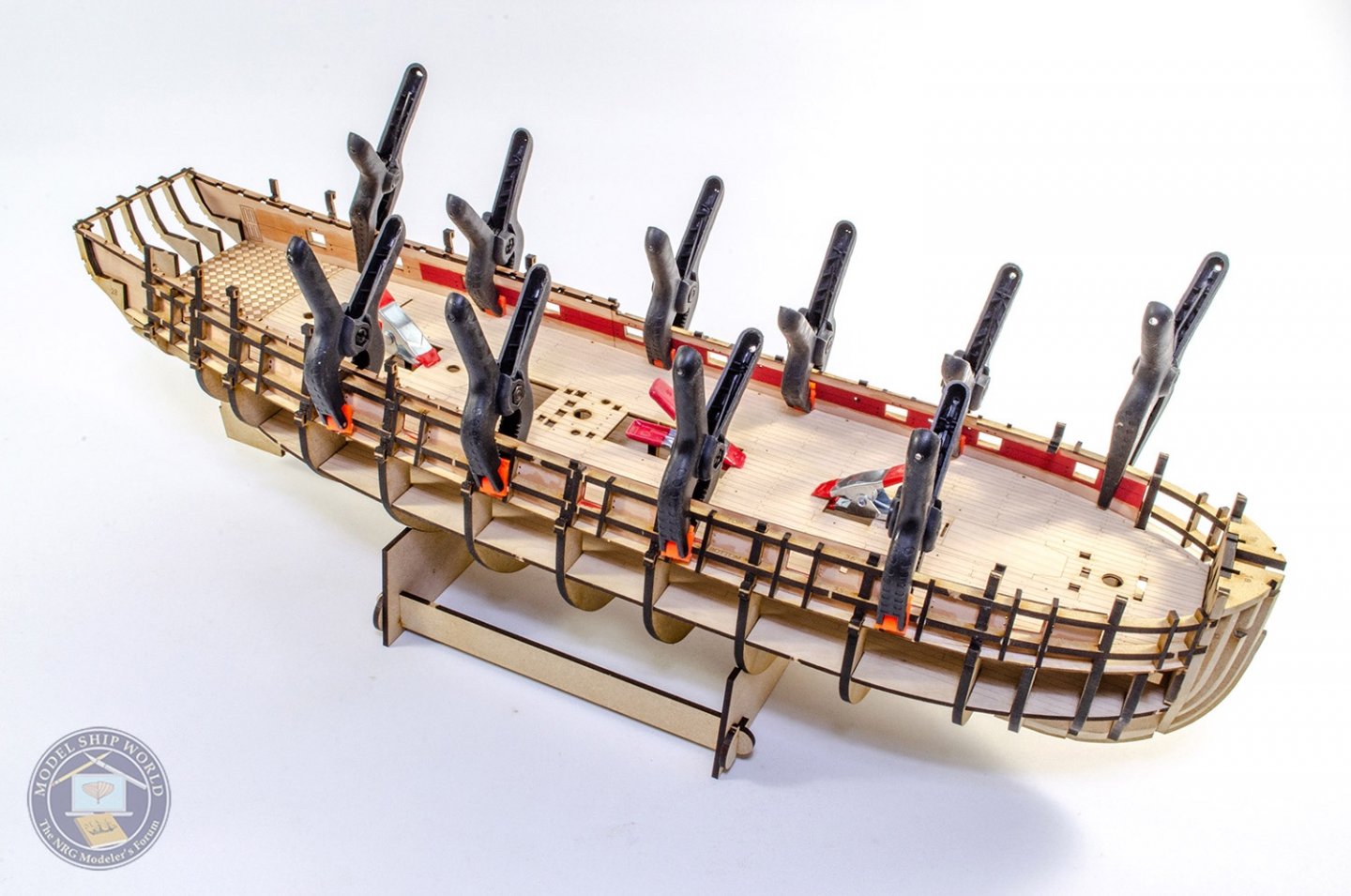
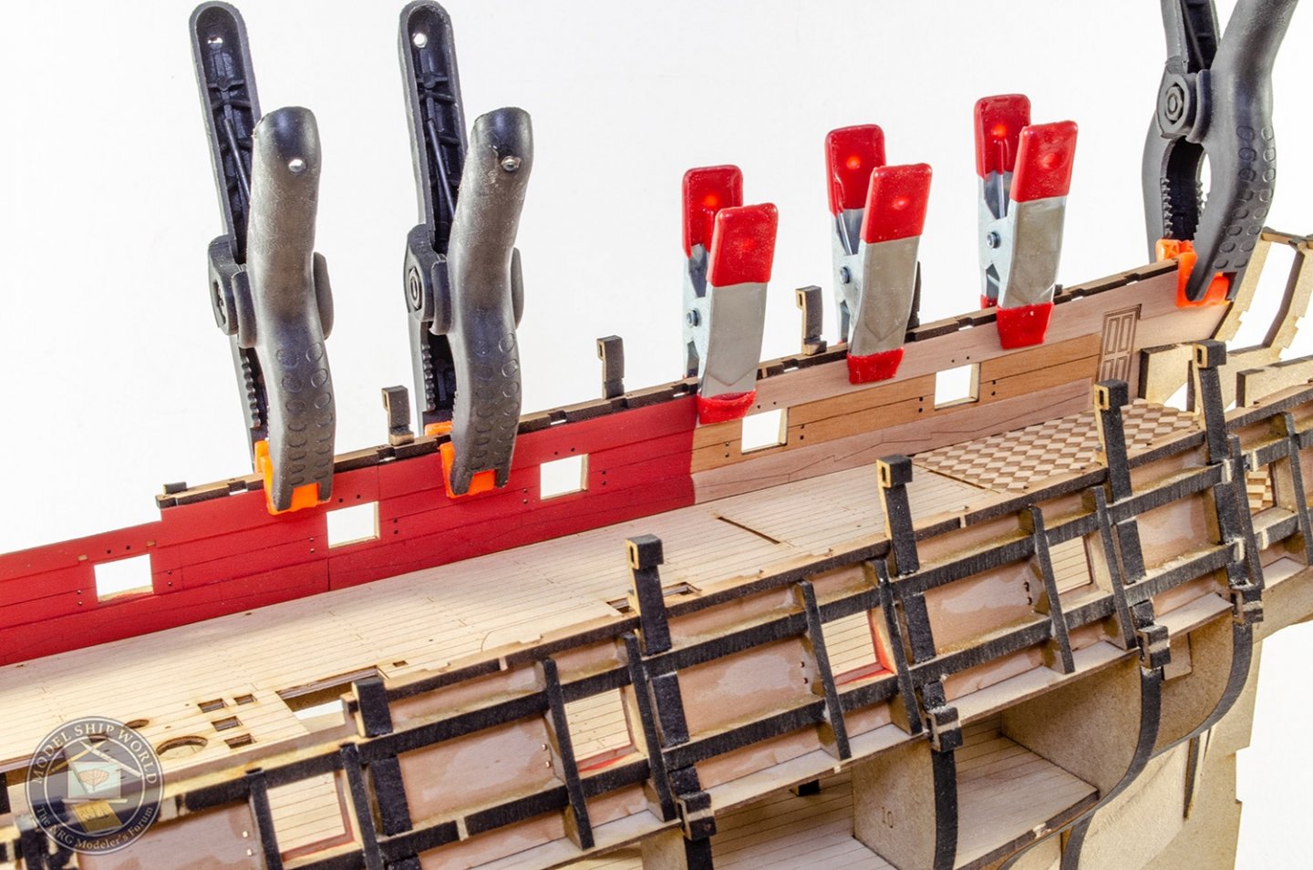
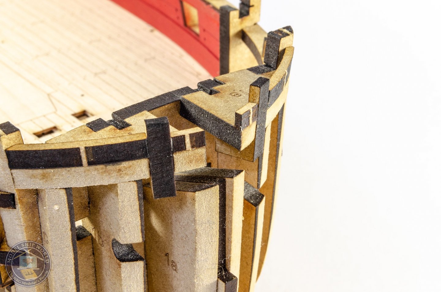
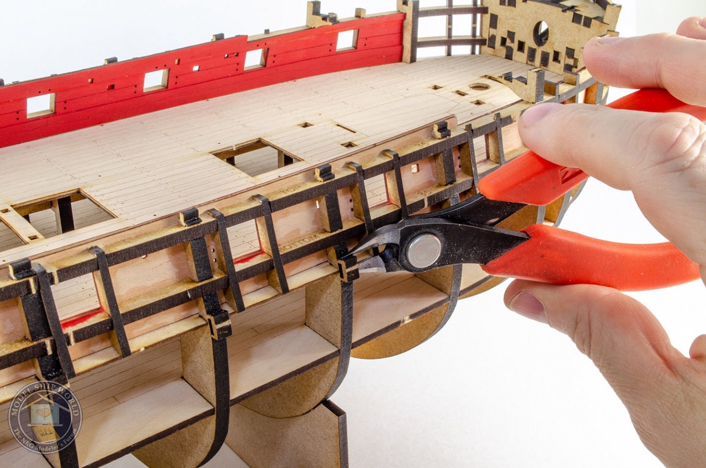
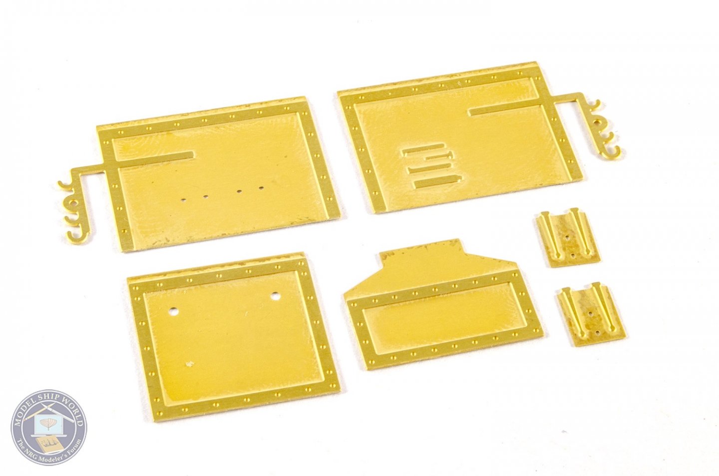
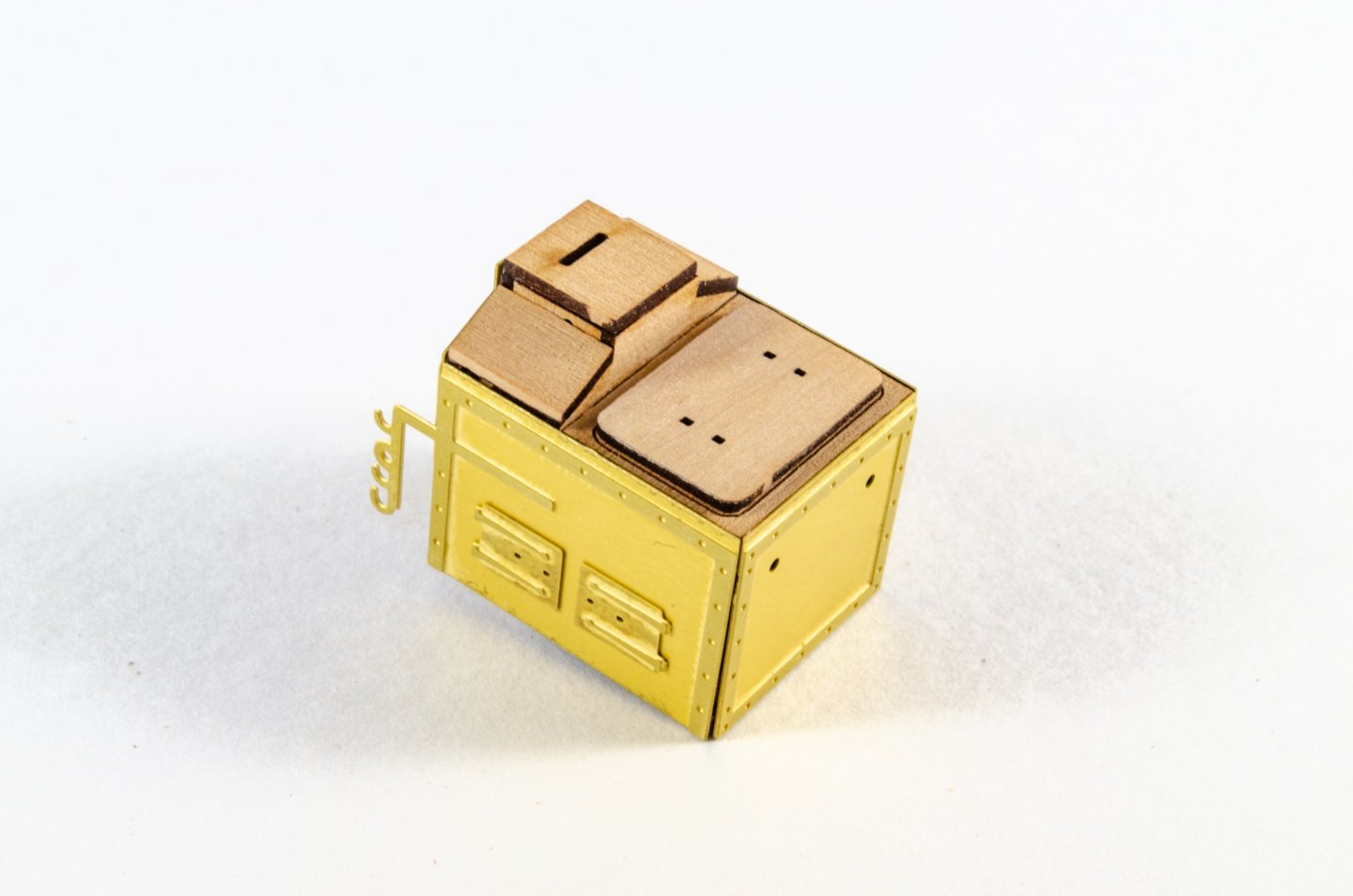
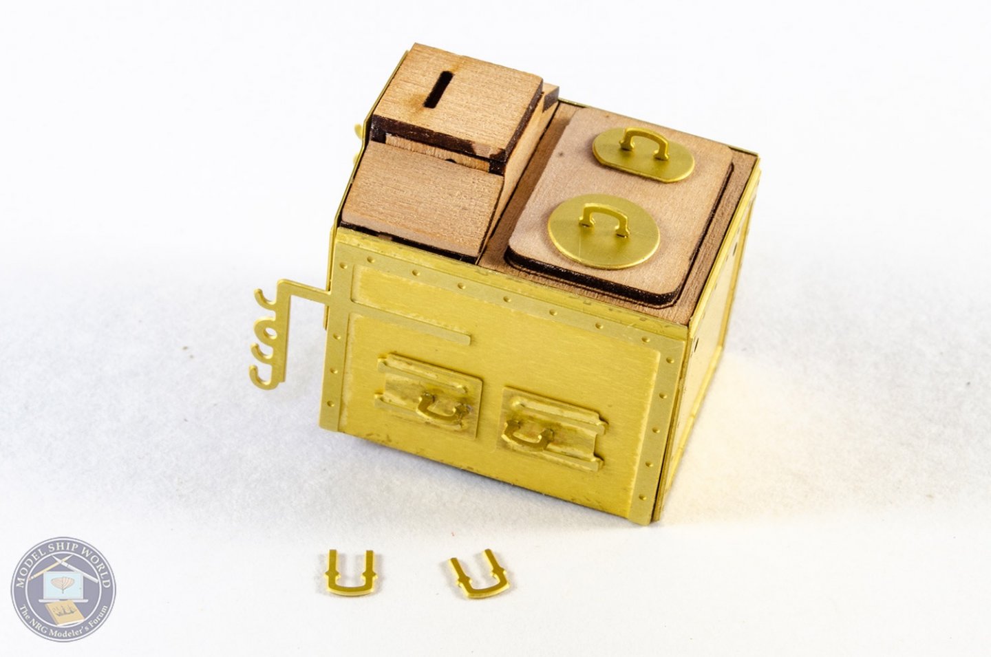
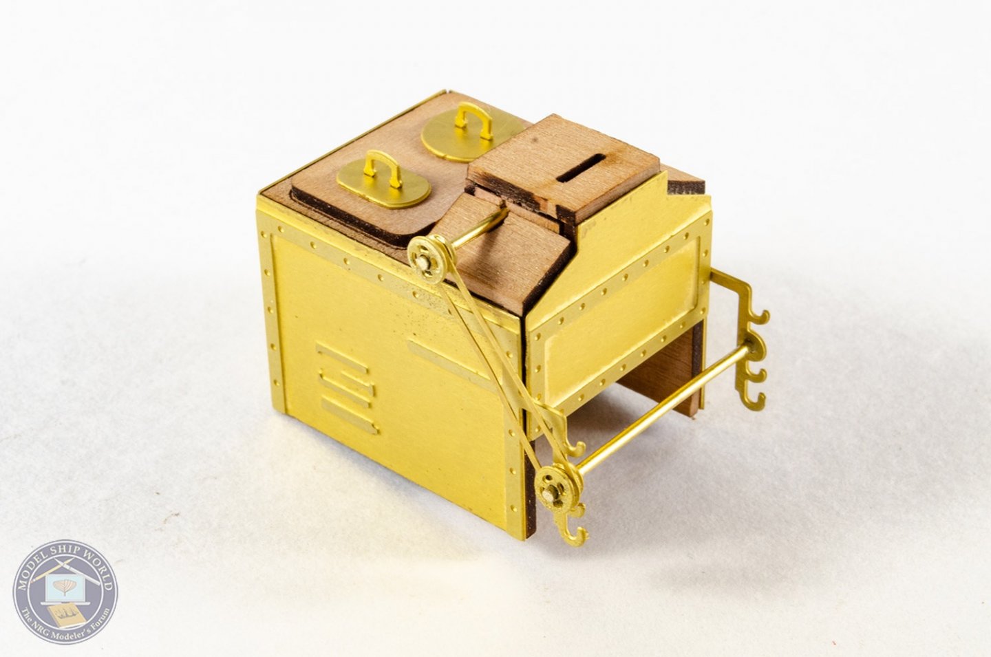
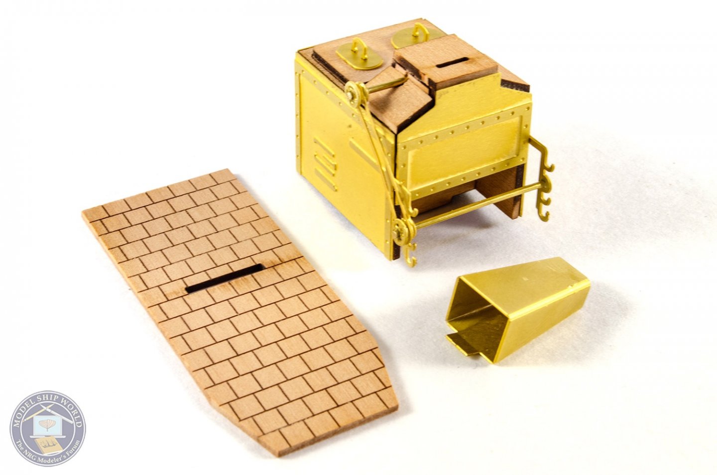
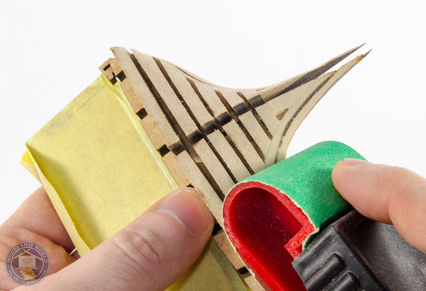
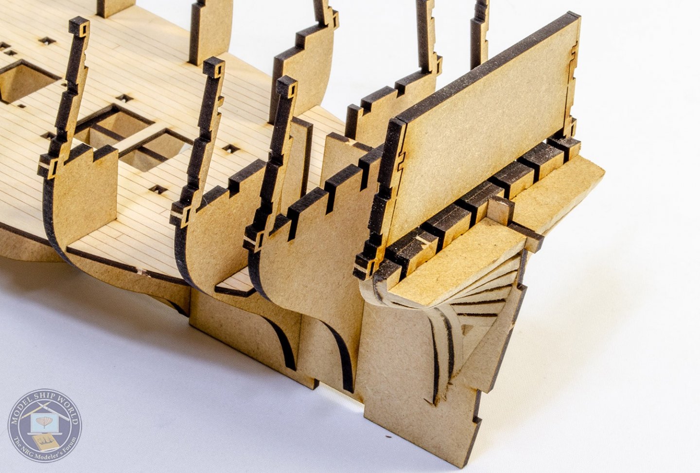
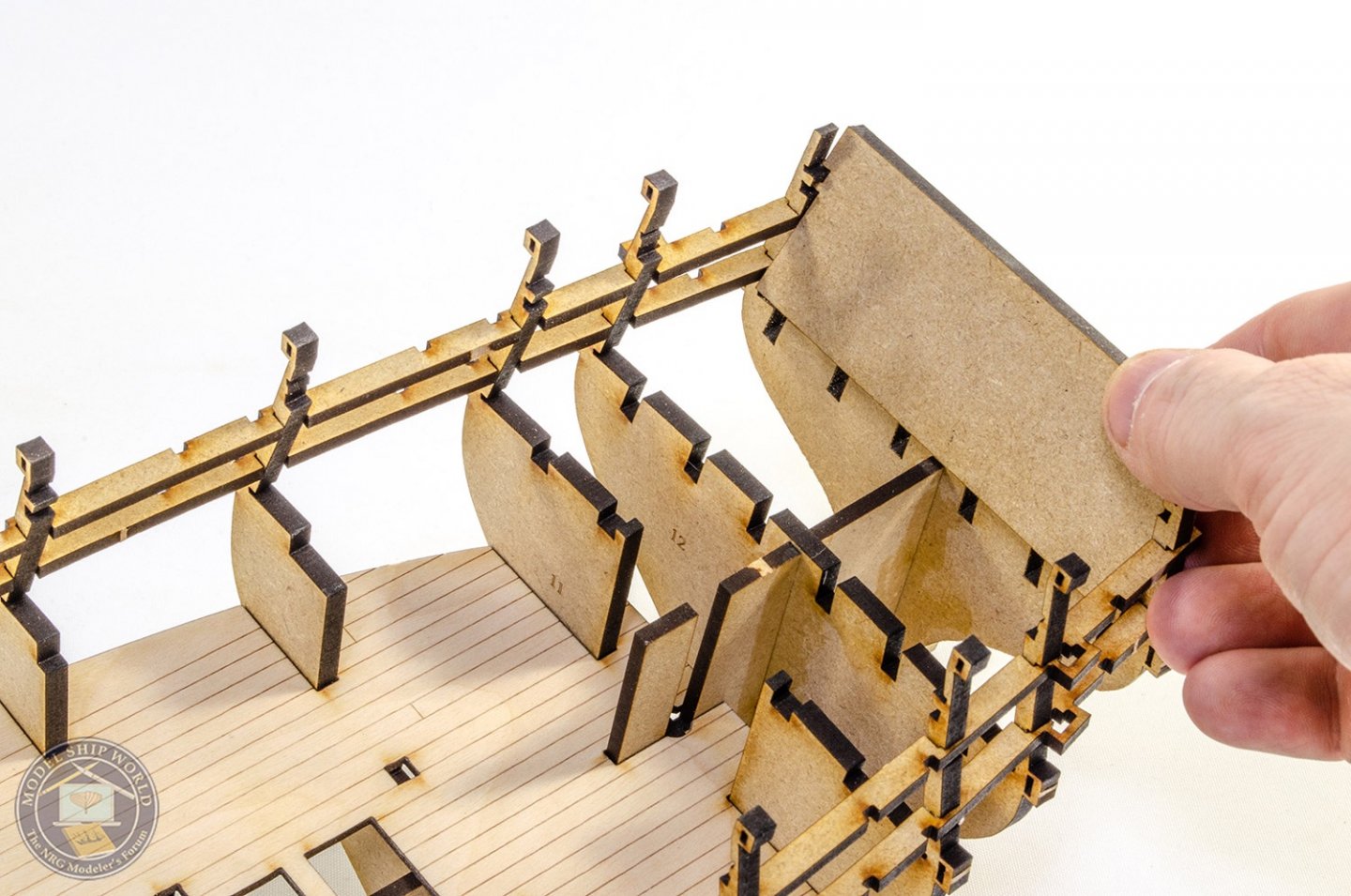
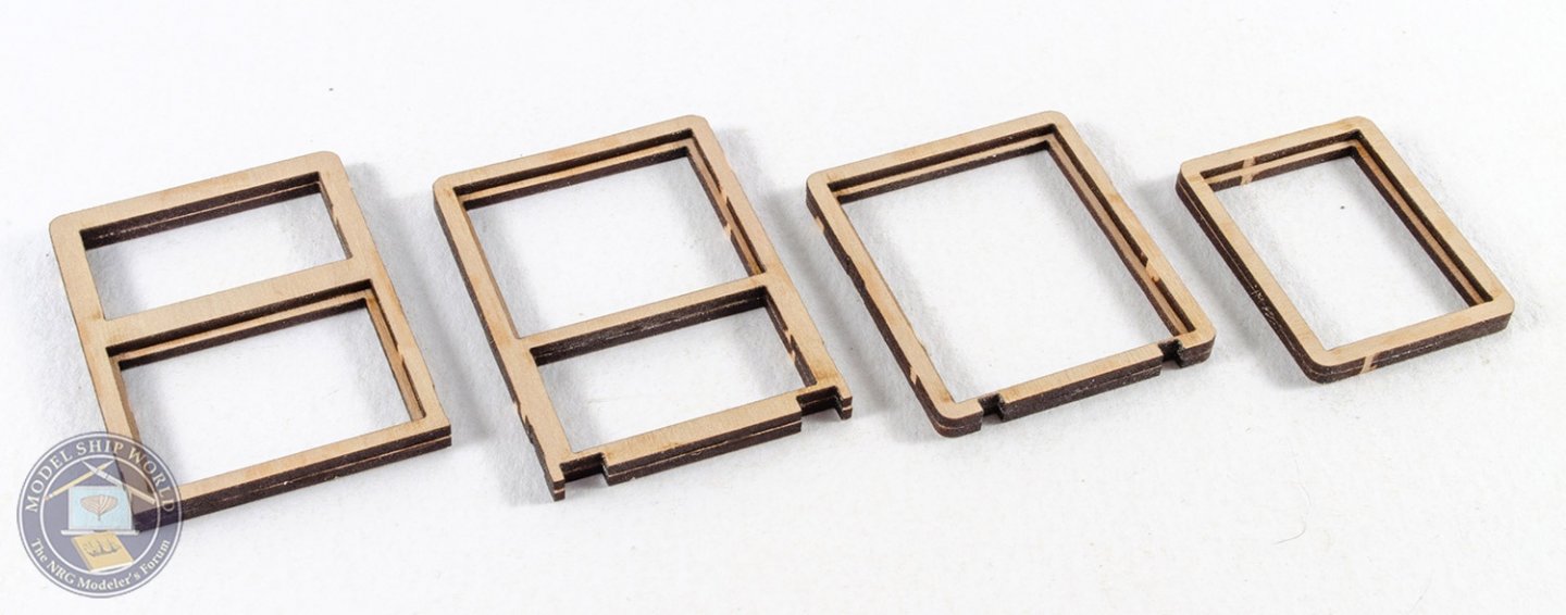
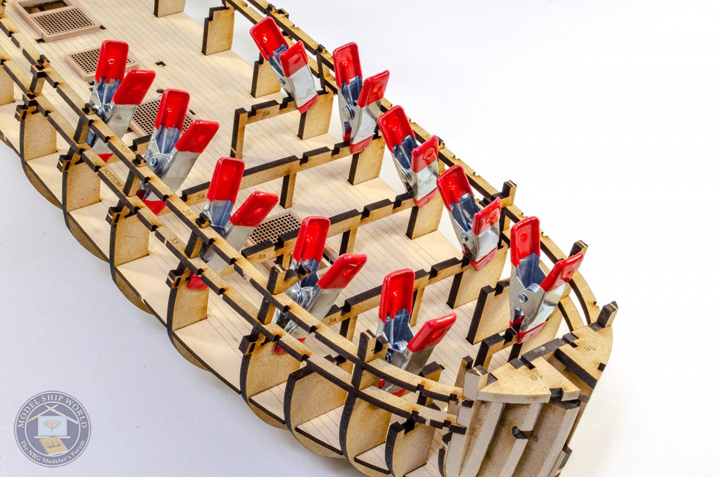
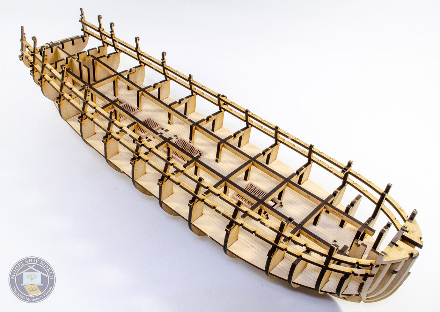
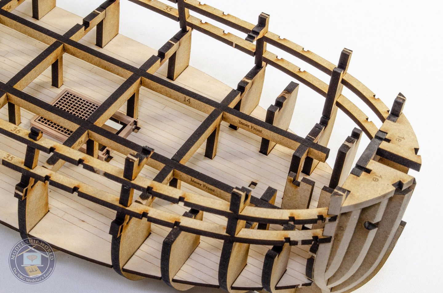
A week has passed, so I have something I can share that's worthwhile. With the basic skeleton now assembled, the bulkhead ears strengthened with the longitudinal strips, and the ply deck fitted...I can now finish the framed cannon ports. These are done in the same way that Chris used on Amati's forthcoming Victory that you may have seen in my build log. These are added in pairs, numbered from the bow, back towards the stern. I push these into position so they are at right angles to the long pot strips I fitted. This is important as they'll need to line up with the inside bulwarks which have the port holes laser-cut. Stern and now filler blocks are now marked, shaped and fitted. I used a Dremel for these for speed. Before the inner bulwarks are fitted, I nee to sand the inner bulwark frames smooth. The best way to gauge this is that the work is pretty much done when all the char is removed. There is leeway in subsequent part fitting even if you sand these a little more than just the char, but the char is a good indication. Another nice feature of this model is that you can fit the inner bulwarks with just clamps, and then paint in the glue from within the frames, once everything is aligned. There's little to no fettling to do here either. The gun ports in the inner bulwarks are also slightly smaller than the framed ports, so you can trim them to size later. Before the rear inner bulwarks are fitted, two pearwood beams are added to the rear hull. These also tie the stern timbers to the side frames. Now the rear inner bulwarks are fitted. Any small gaps between the bulwarks and ply deck will be hidden with the deck and the spirketting. Unlike Chris' test hull, this model will be painted, and the inner bulwarks will be painted red. However, they won't be painted in the cabin areas, but left in varnish. To mark the extent of the paint, I test fit one of the cabin bulkheads. The inner bulwarks can now be painted. Before paint, the surfaces are sanded with 320 grit paper, and wipe on poly is applied only in the area of the bulwarks that will be painted (spirketting will be fitted to upper and lower bulkheads). I don't like to glue parts onto surfaces where poly has been applied, so take this into consideration. For paint, I airbrush Tamiya Flat Red over the timber, then give a very light brush coat of Vallejo Flat Red, which gives a very pleasing finish. Once the masking is removed, the laser-engraved maple deck is then fitted. Some adjustment is made to the edges so it fits properly. I use Titebond Extra for this to allow me more time to manoeuvre things. Clamps hold down the deck adding the edges. Small clamps in the middle areas. The spirketting is also painted in the same colours, but only in the area that will require it (not the cabin!) This is then fitted. Cabin seat patterns are now adjusted to width and fitted. A little sanding of the MDF frame area needs to be done first, but not too much. Some MDF parts are now added to the bow area to help with fitting the outer patterns. Anything above deck level will eventually be broken away when the deck is fitted. Finally, those safety gates which gave strength to the unsupported bulkheads, can be removed as the whole structure is now very strong. After this, the hull can be faired for fitting the outside patterns and planking. Whilst I was waiting for stuff on the hull to dry, I worked on the stove. Here you see the pear carcass being assembled. And of course, this is mostly sheathed in photo-etch. I'll not be sanding this hull until later this week when I finish work for Easter. That means I can do that task outside, but I will work on some deck stuff this week....maybe cannon. Until next time 😁


- 355 replies
-
- 48
-
-
- vanguard models
- Sphinx
- (and 1 more)
-
NEW Vasa kit from Artesania Latina -- looks to be quite good
James H replied to md1400cs's topic in Wood ship model kits
All Artesania instructions are now supplied on a CD. It can be problematic if your laptop doesn't have a drive, like my MacBook Pro. I took the disc to work to have it transferred to a USB drive so I can access for my review. Another problem is that I don't like to have my Mac in the workshop due to dust, so the only real option is to have it printed. -
NEW Vasa kit from Artesania Latina -- looks to be quite good
James H replied to md1400cs's topic in Wood ship model kits
For me, I can't understand why paint the hull brown 🤔 Surely better to use nice, quality timber and varnish, surely? -
Ok, I've fixed the Artesania Latina link. Also, I received a kit from them last week which I'll review in the next week or so.
-
That's the Amati sanding block. I quite like that as locks the paper in place and has one curved end.
- 355 replies
-
- 4
-
-
- vanguard models
- Sphinx
- (and 1 more)
-
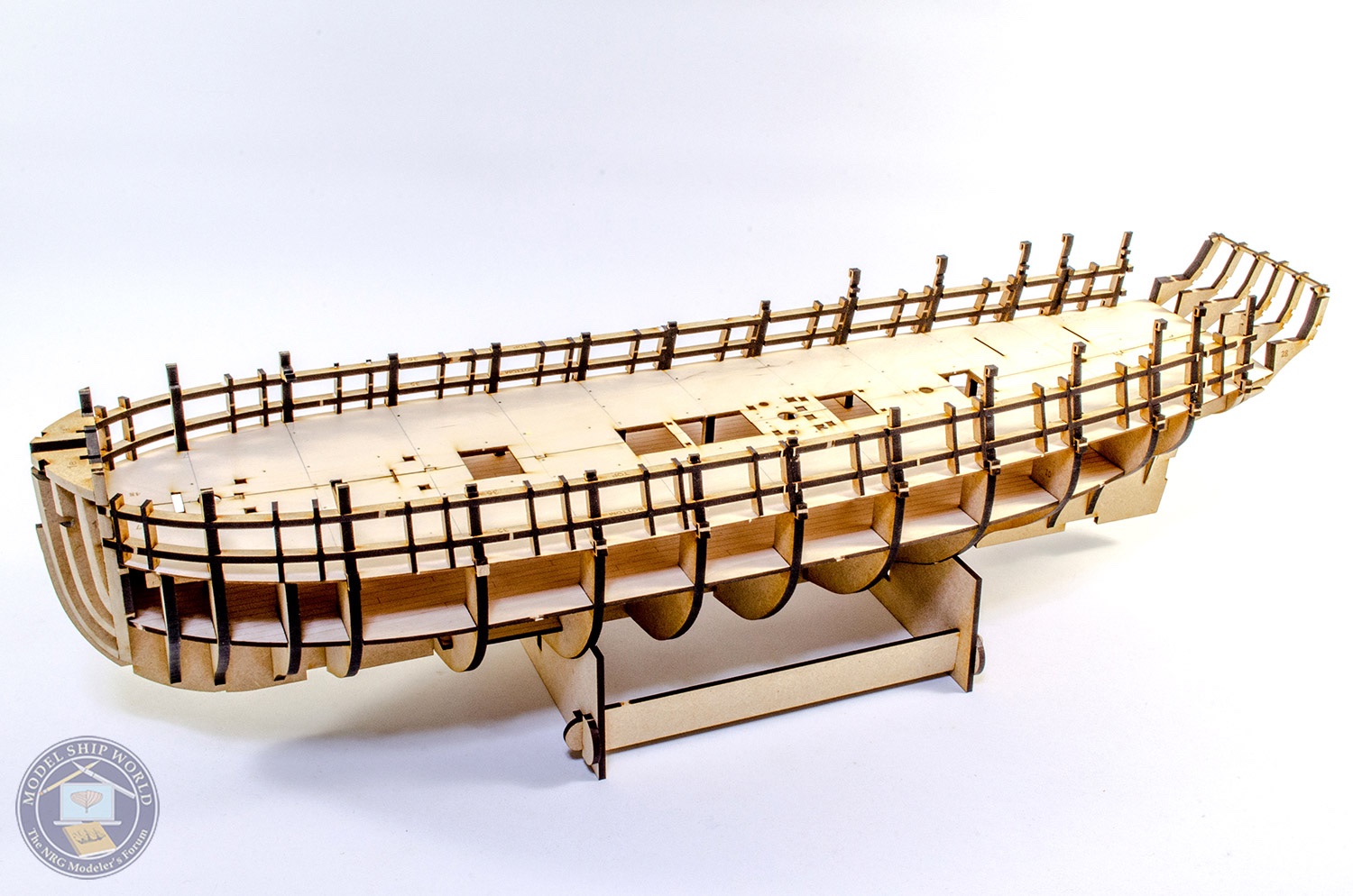
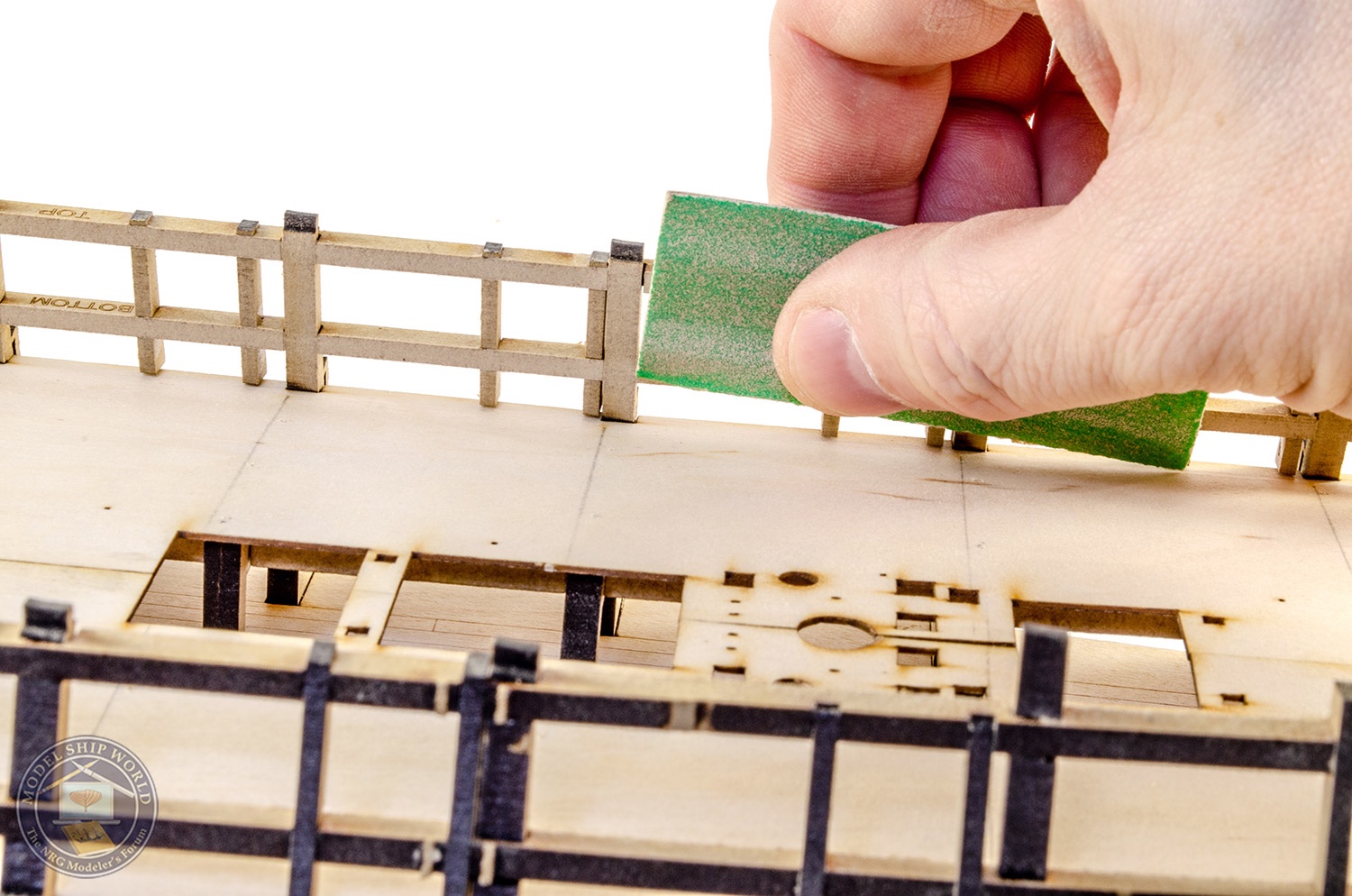
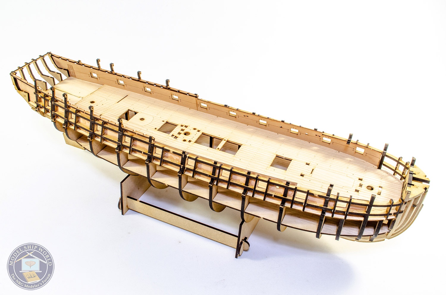
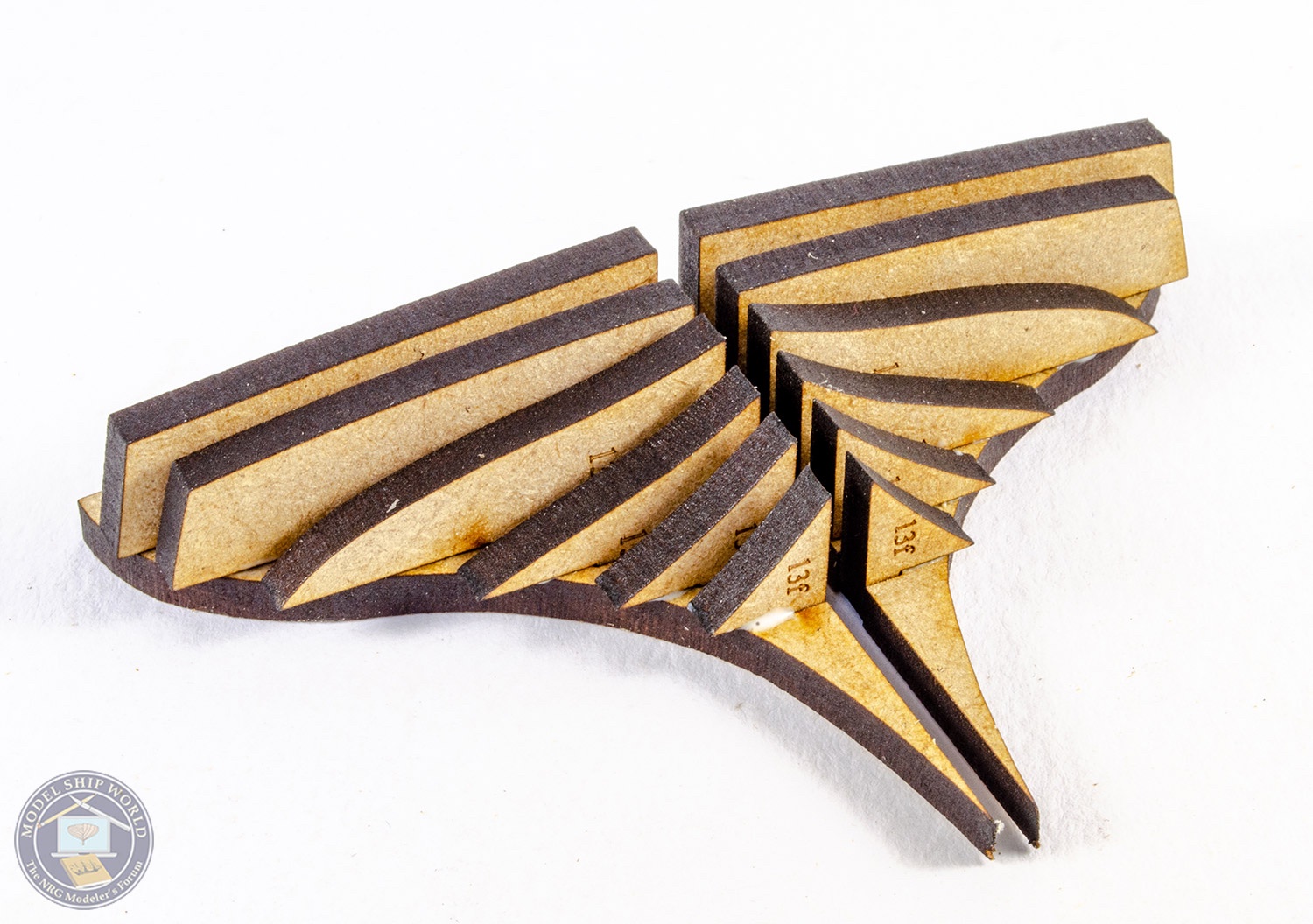
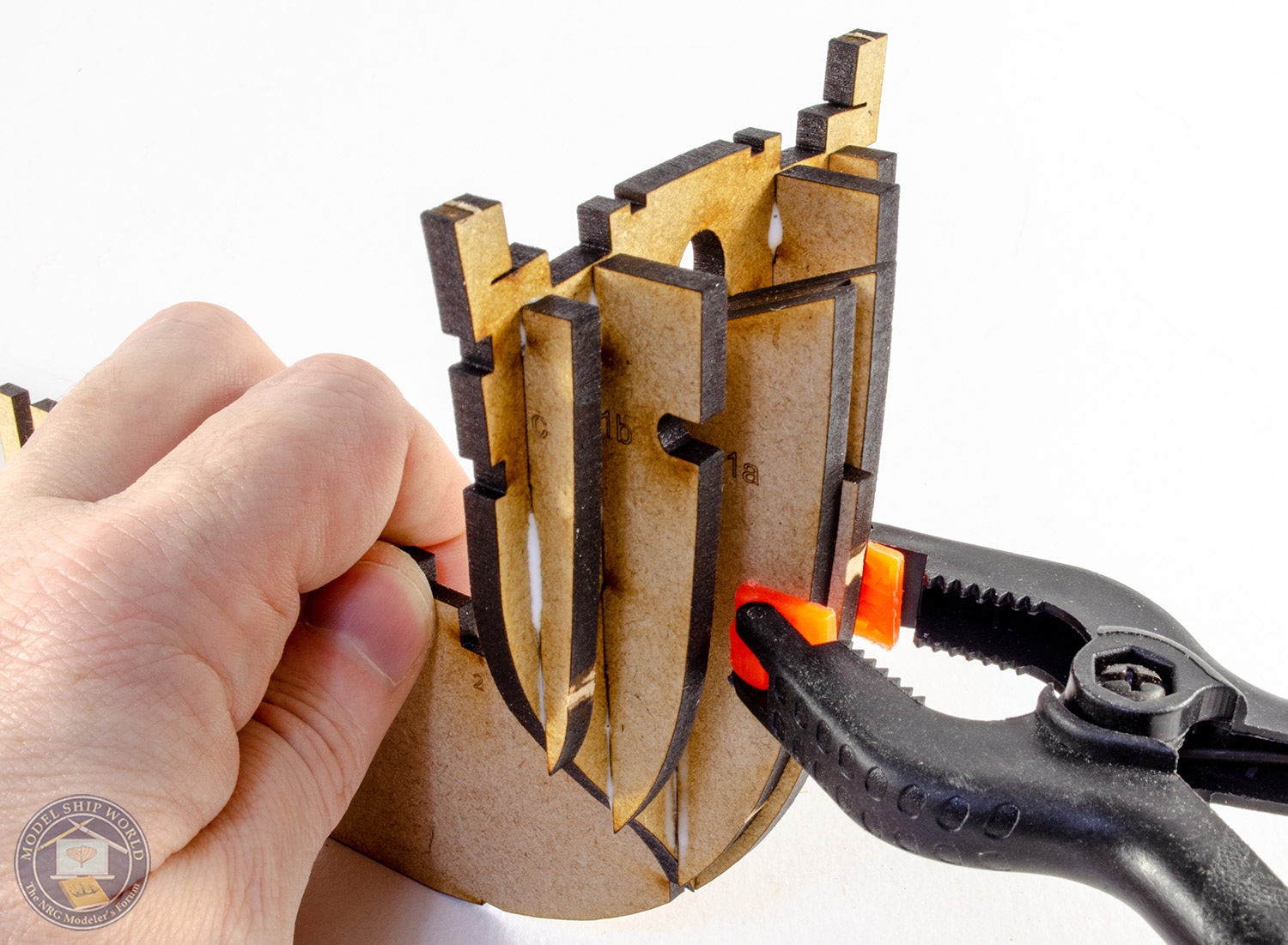
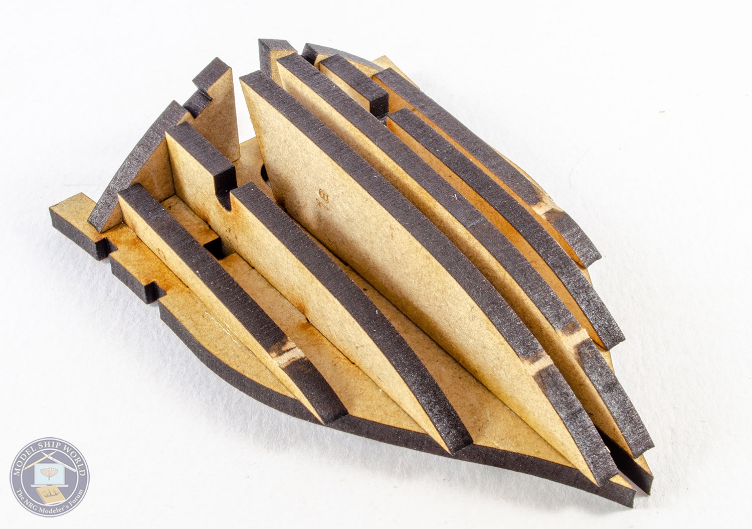
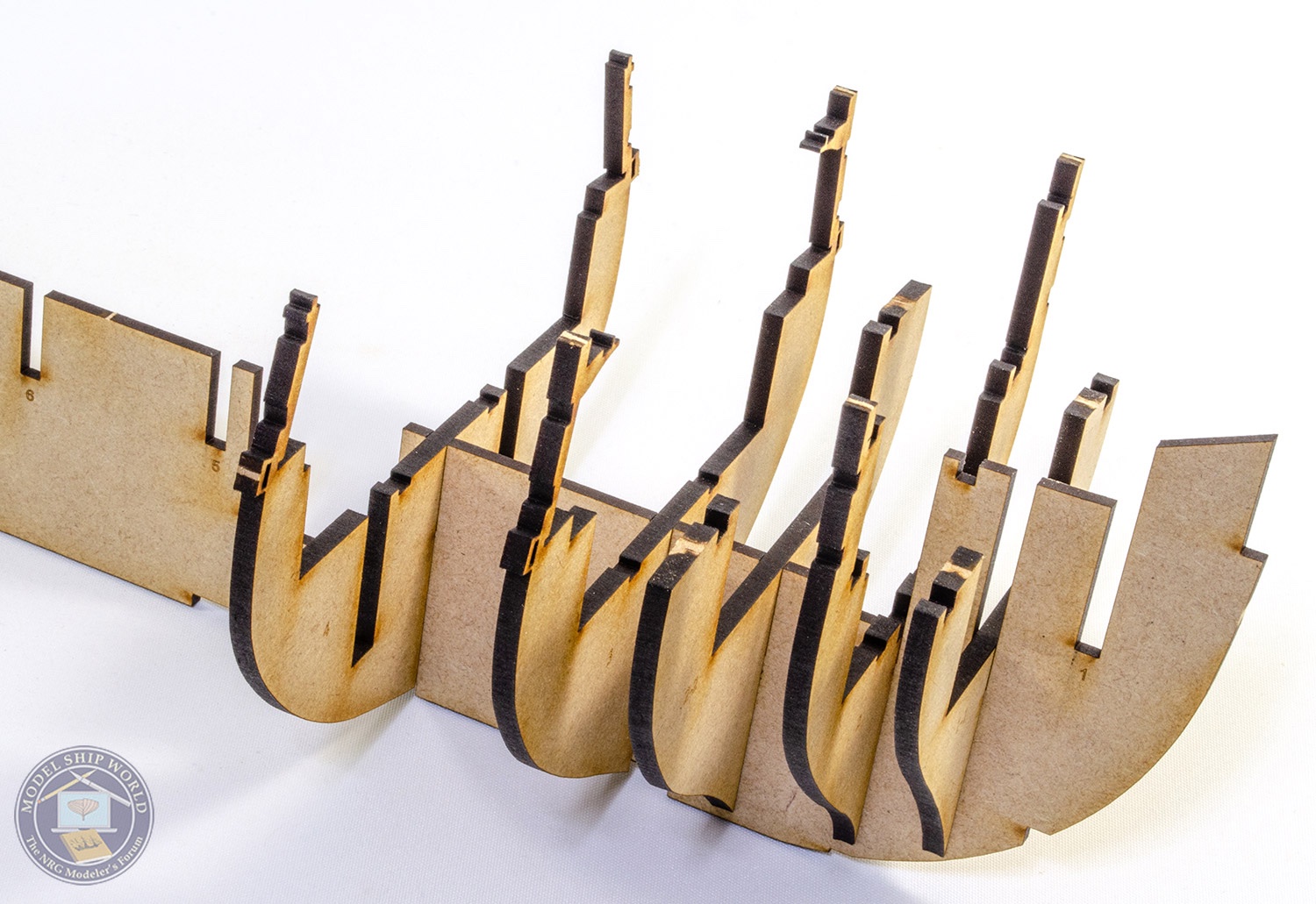
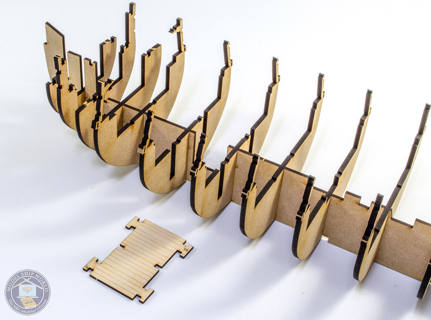
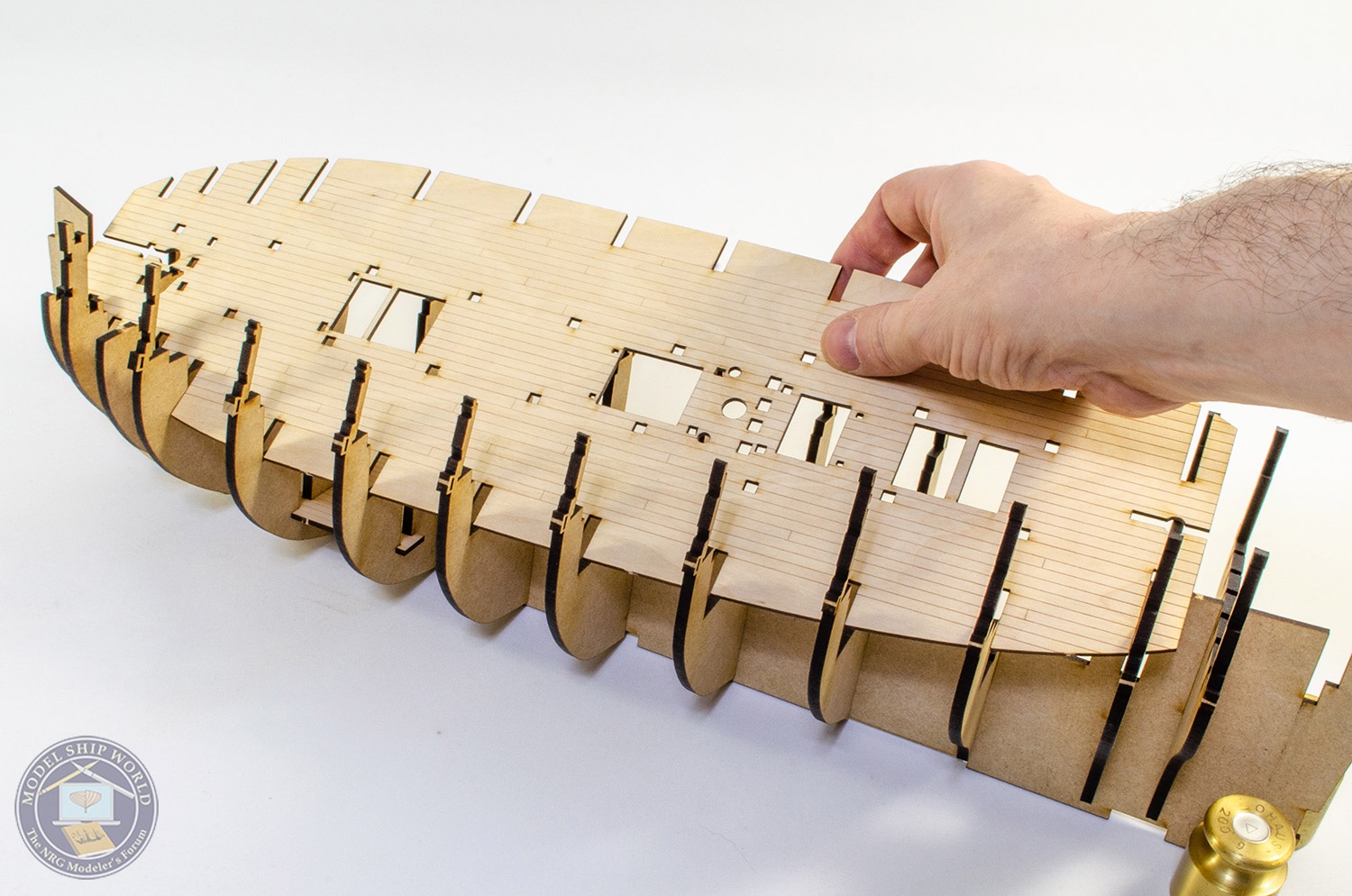
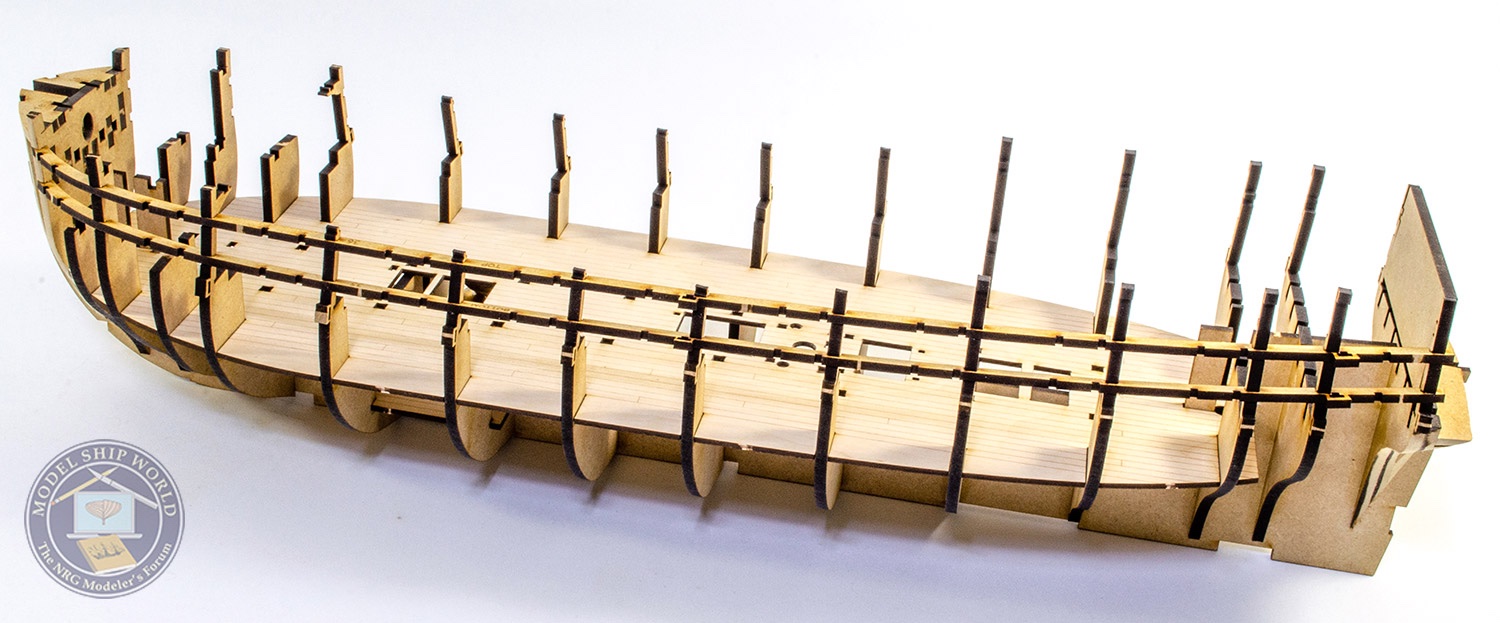
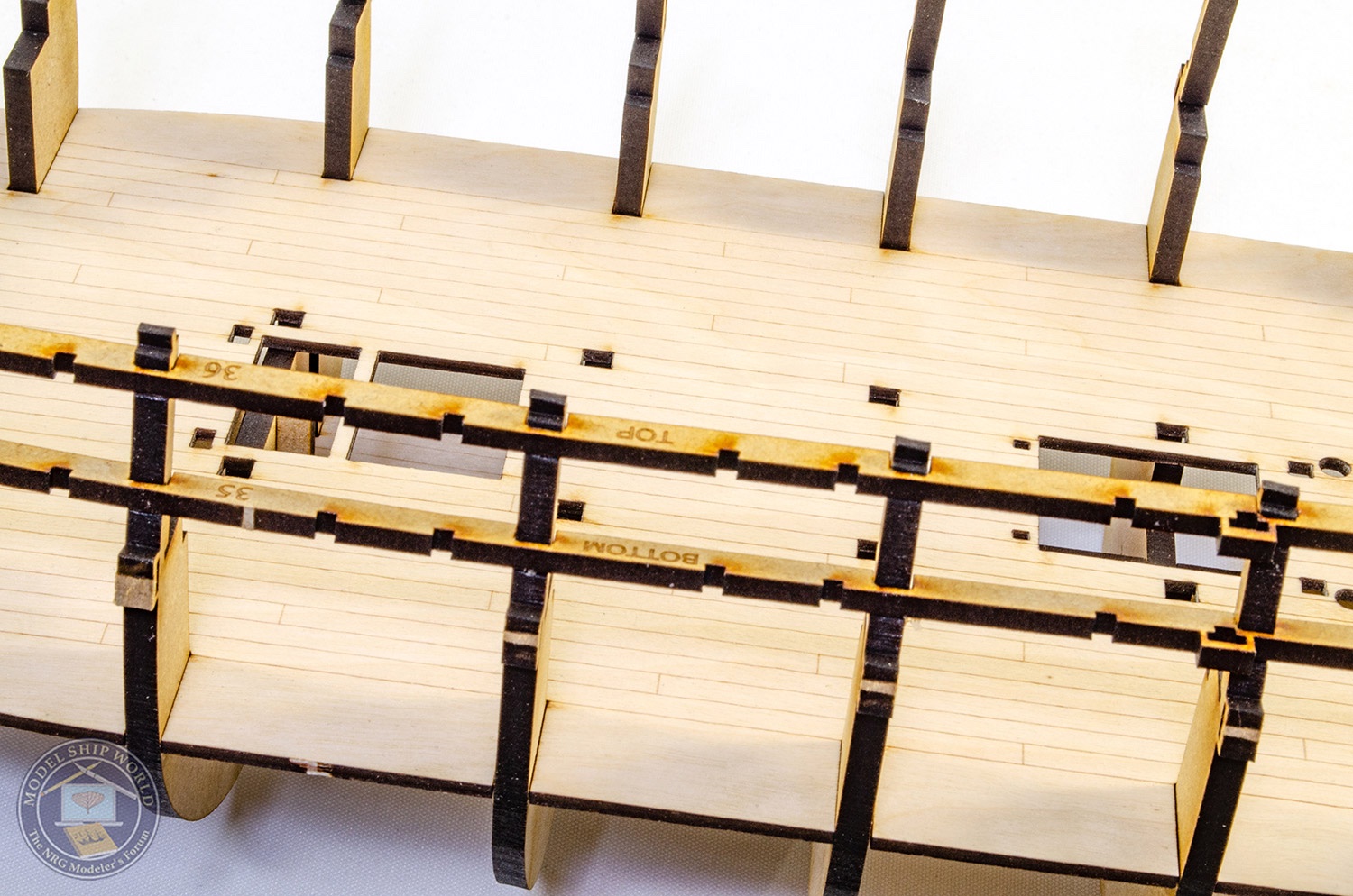
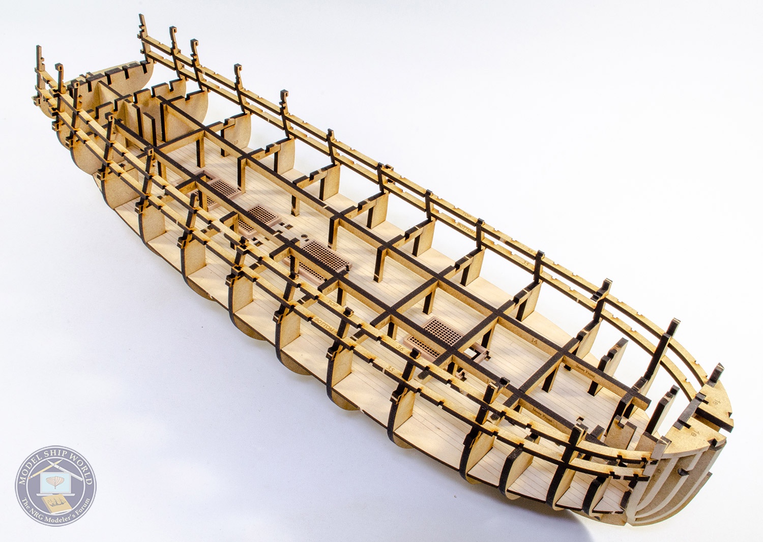
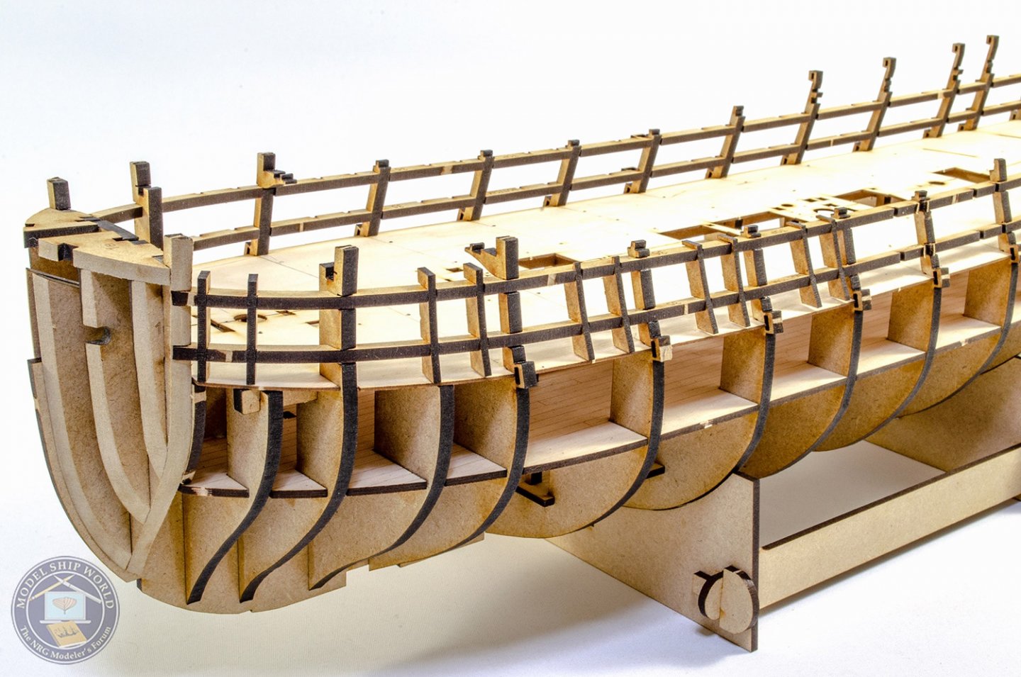
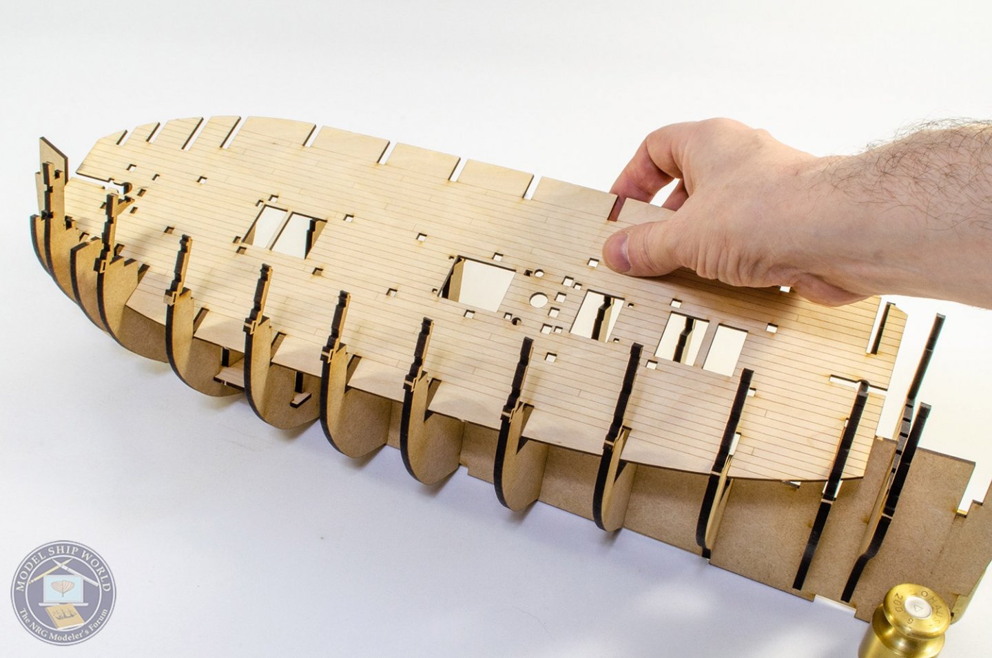
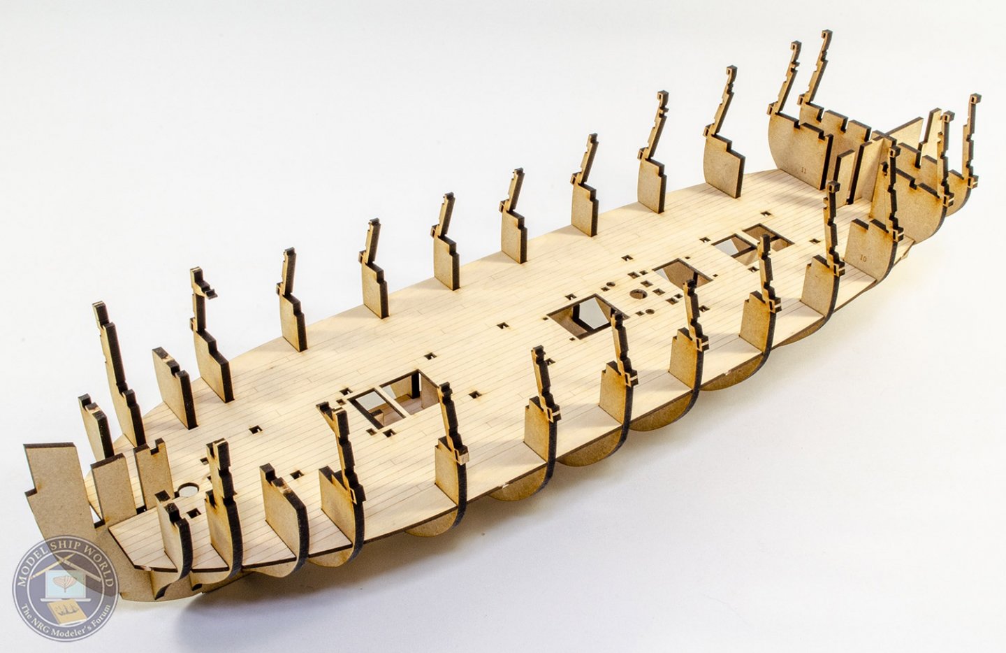
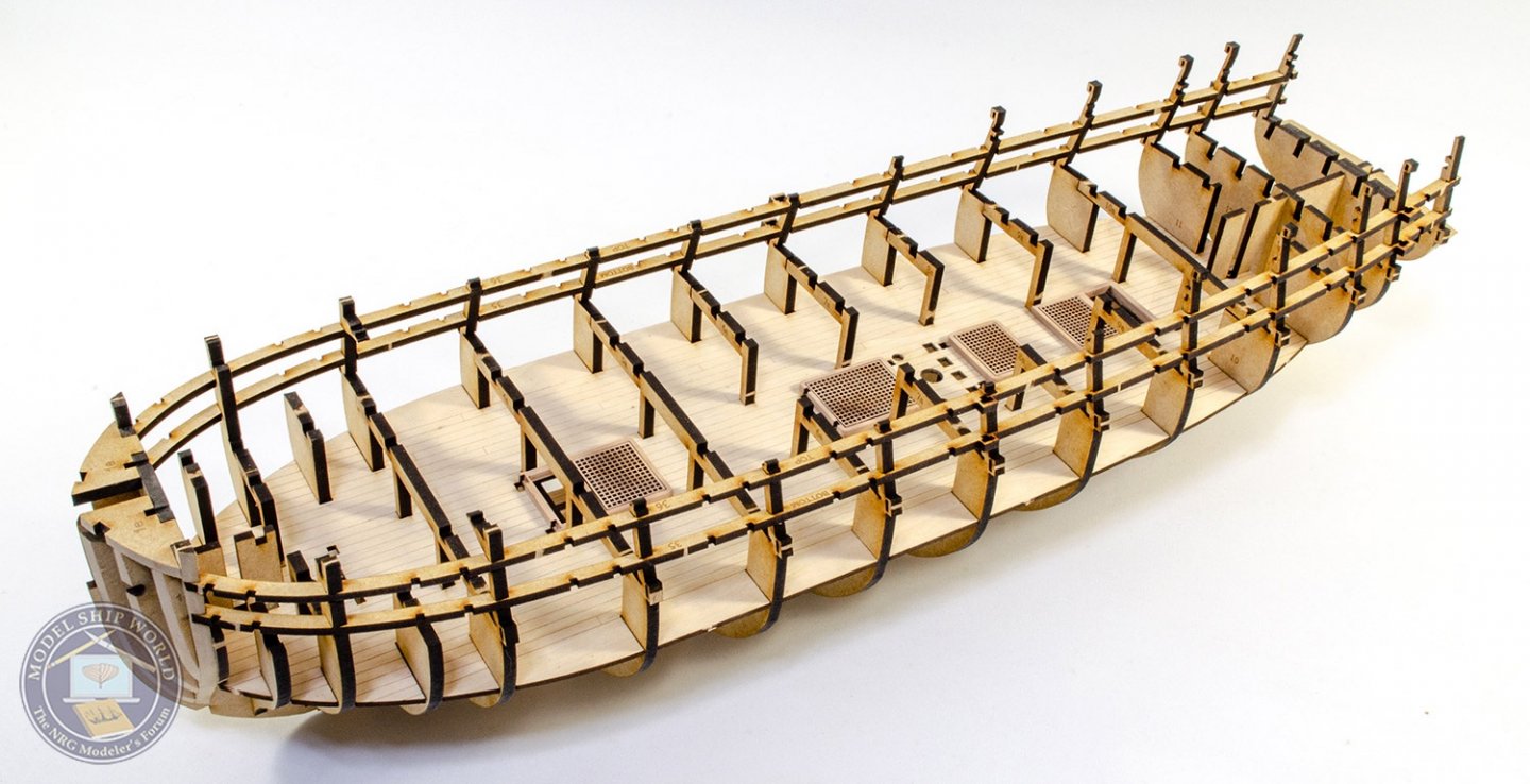
Been a busy weekend at chez-Hatch. I wanted to het the hull skeleton as far as I could so I can fit the laser deck and red bulwarks/spirketting this week. Work starts on the first and last bulkheads which are fitted with their bow and stern patterns respectively. The first bulkhead is dry fitted to the false keel so the two adjacent patterns sit snug to the keel. A clamp was deployed until fully set, then the assembly was removed from the keel and a sanding block/Dremel used to shape. I really do recommend a rotary tool for shaping the stern. It will be make things much, much simpler. Before shaping the stern, the assembly was slipped back onto the keel and glued to the bulkhead which sits adjacent to it. Shaping was done after removal. The tape on the stern assembly issued to protect the filler panel from breaking away. With so many bulkheads and interlocking slots, I always like to dry-fit all parts where possible, and then paint wood glue into the joints afterwards. This method works perfectly well, and you can dilute your glue too if you wish. Modern wood glues seem to set too quickly that I see this as a way of making sure everything seats before the glue turns. With the bulkheads slotted into position (minus the bow and stern assemblies I just made), the small orlop deck section is slotted into place, followed by the laser engraved ply lower deck. Care needs to be taken not to damage the bulkhead ears. If you look closer, you'll see the bulkheads have safely gates on the outside, protecting the ears somewhat. These are removed later, before fairing the hull. The model is now turned upside down and supported while I paint wood glue into the various joints between the MDF and ply parts. The bow and stern sections are now finally slotted into place and glued. It's important that the bulkhead ears are protected from quite early on in the build, so I changed the sequence so that the longitudinal gun port strips are now glued into place. These are labelled 'TOP' and 'BOTTOM' to remove any confusion. The blanking/strengthening section on the rear bulkhead can now be carefully twisted away as the bulkhead ears are now protected. We also need to later fit the stern gallery timbers which will run through this area. The first pear wood is now used with the grate coamings. These are assembled and the outer edges have their char removed. I also remove star from the two open sections that won't have grates fitted. Now, the deck beams can be glued into position. Clamps ensure they are aligned and vertical. With these in position, the coamings and gratings are glued into place. Four longitudinal deck support strips are now fitted, with one pair being 'OUTER' and the other 'INNER'. Finally, for this update, the ply deck is fitted. These sections clip into the bulkhead ears so they are self firmly at that point. All you need to do is to pin them down in the middle. I also chose to paint glue into the joints after fitting the deck parts. More as soon as I have something to show you. 😃


- 355 replies
-
- 43
-
-

-
- vanguard models
- Sphinx
- (and 1 more)
-
You'll be surprised just how this build could be built by someone only just intermediate. Chris has created a kit that is designed to be as foolproof as possible and it's my task to create a manual which takes the sequence and makes it simple and clear to the average modeller. I hope I can do that. I love Barcelona. Visiting again by ship next summer (2022), but only for the day.
- 355 replies
-
- 12
-
-
- vanguard models
- Sphinx
- (and 1 more)
-
I love this kit (having so far failed to finish mine), so following along ☺️
-
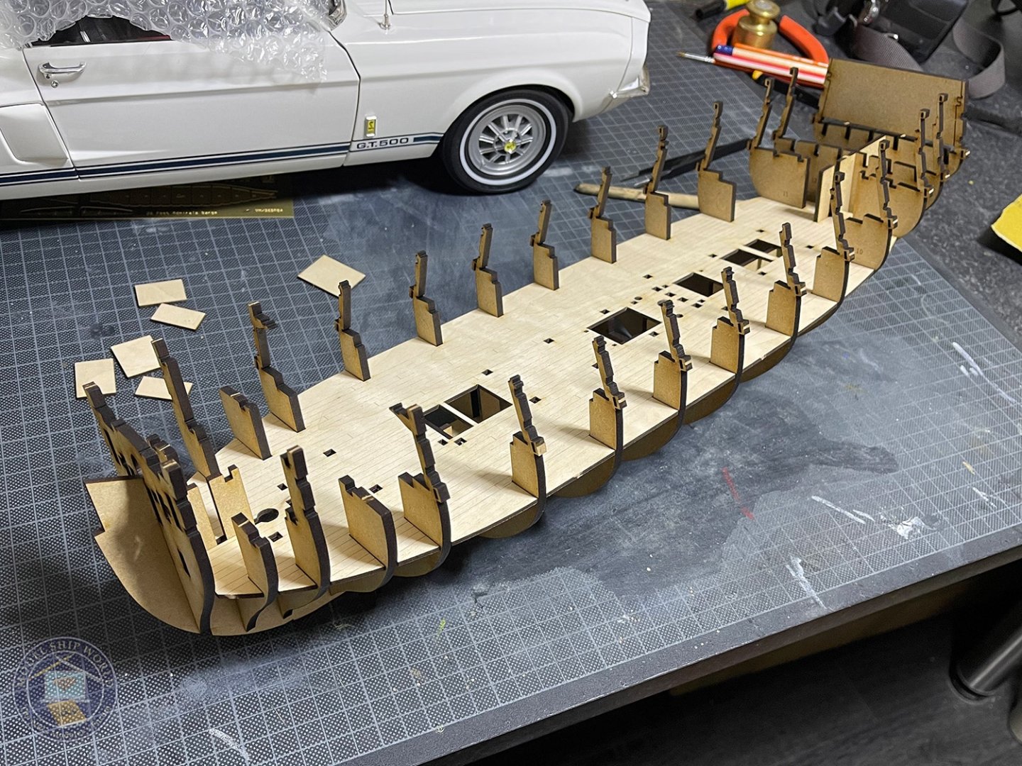
Work officially starts on this tomorrow, but I thought I'd do a quick test fit of the bulkheads, and the lower deck and orlop deck section. The fit is absolutely perfect and everything nice and square. This will give a rough idea of the genesis of this build before I crack on with the instructions images tomorrow.
- 355 replies
-
- 32
-
-
- vanguard models
- Sphinx
- (and 1 more)
-
Hi Alex, The model you see is the design prototype from Chris, so I had nothing to do with that one.
- 355 replies
-
- 2
-
-
- vanguard models
- Sphinx
- (and 1 more)
-
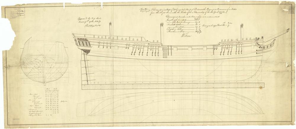
I suppose the only problem is that there isn't a finished model to post pics of. Chris has test images in his Vanguard Models traders topic that have been there for a while. That kit also has numerous changes which will be seen in this topic. Of course, this one will also be masted and rigged, unlike the test hull Chris made. There is a profile to be seen on the National Maritime Museum page:
- 355 replies
-
- 24
-
-
- vanguard models
- Sphinx
- (and 1 more)
-
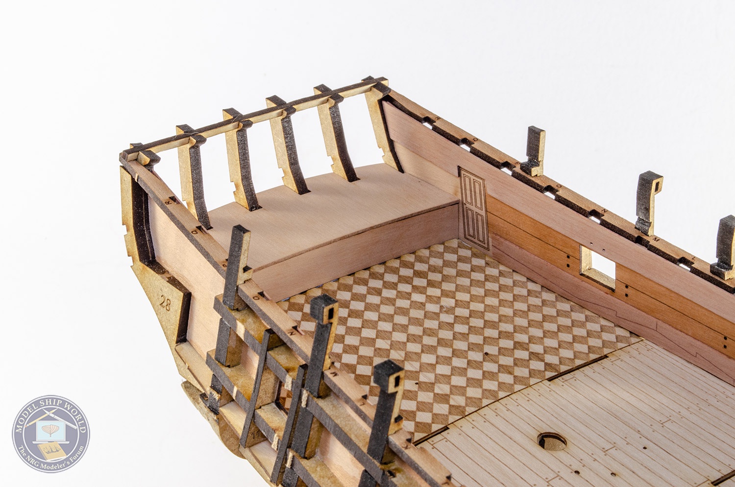
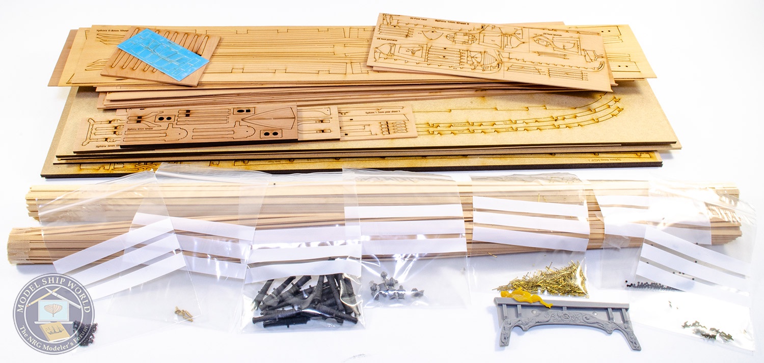
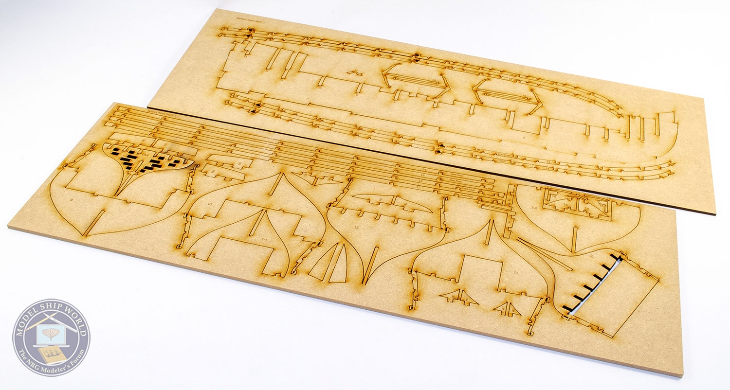
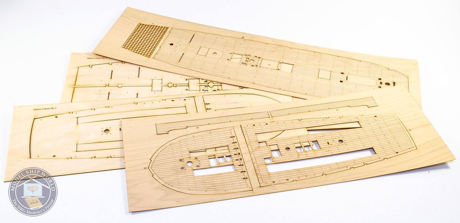
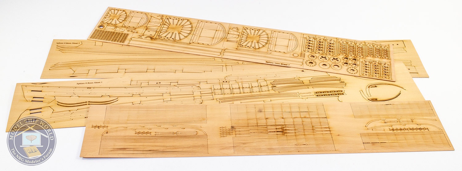
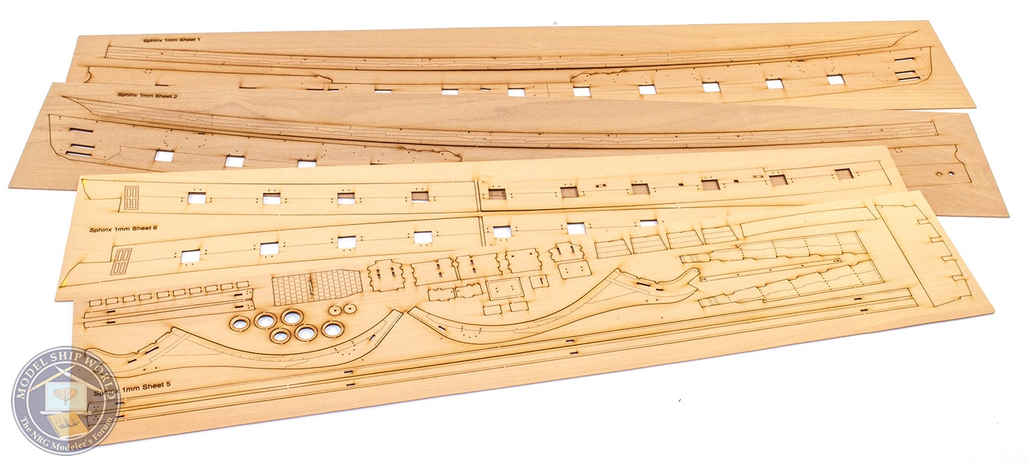
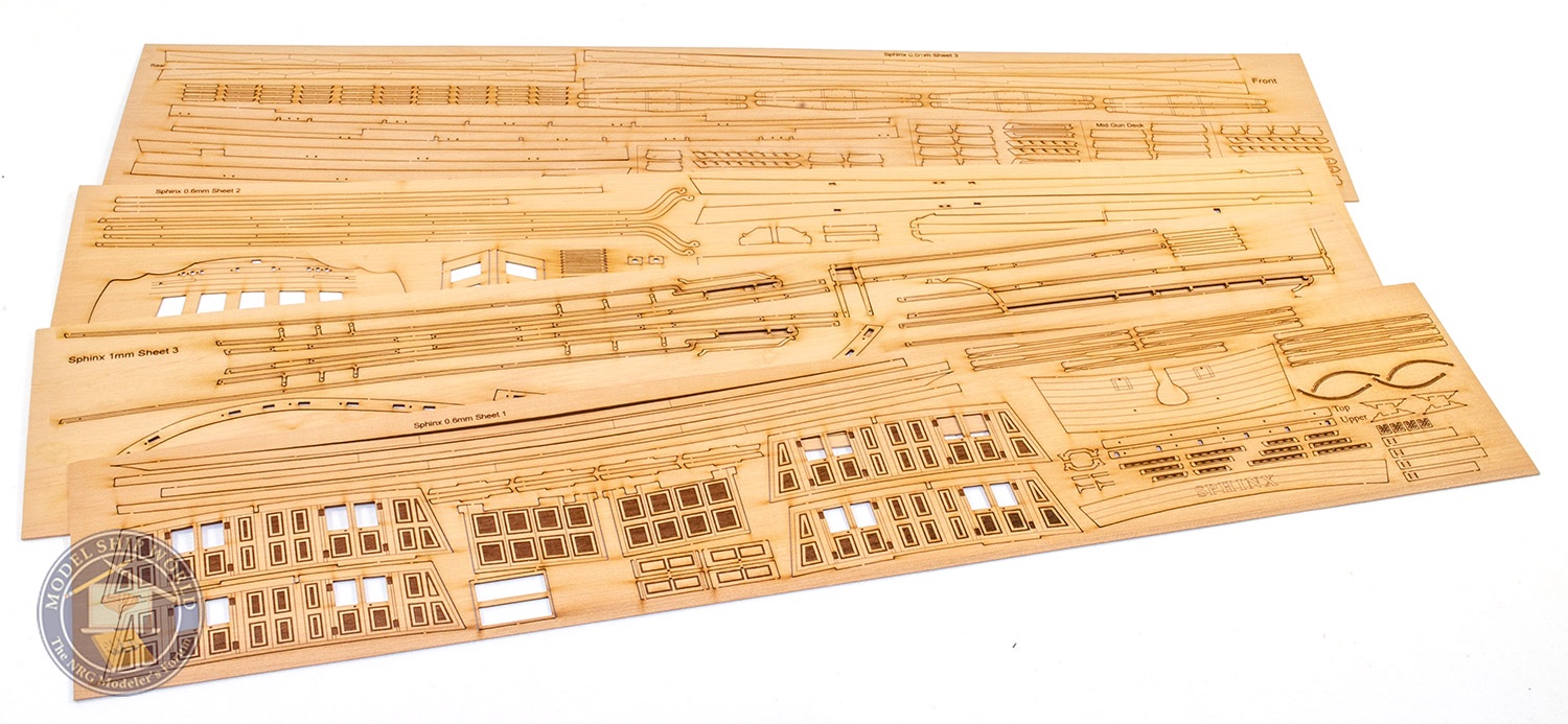
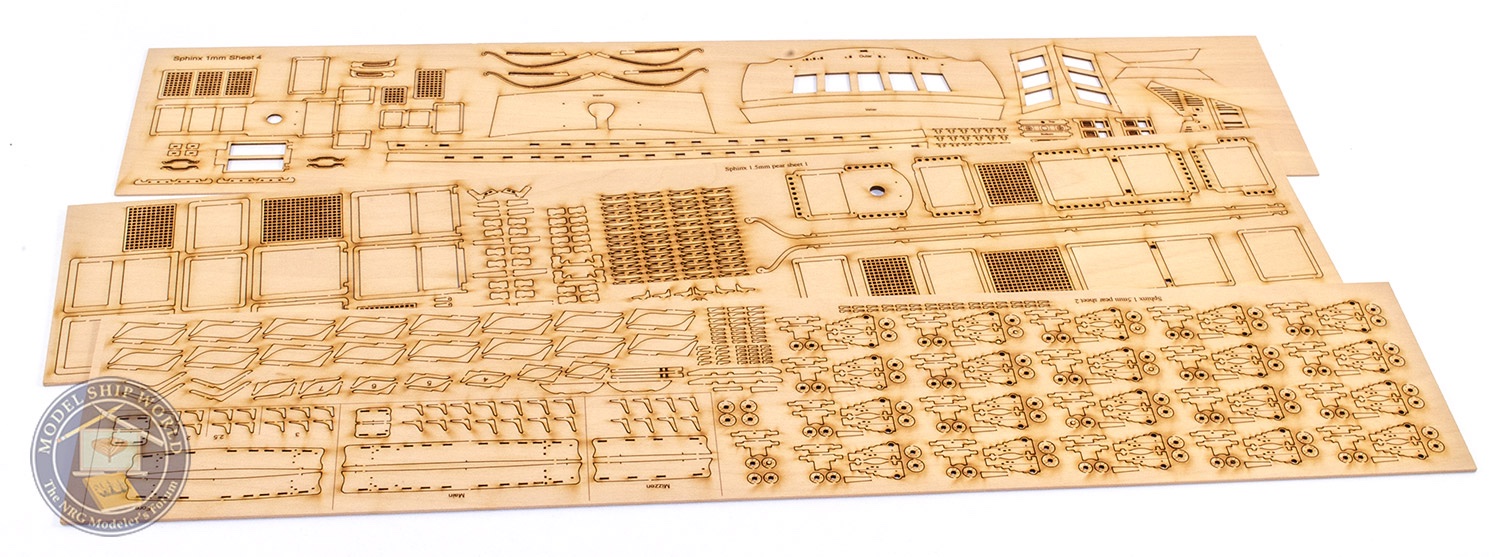
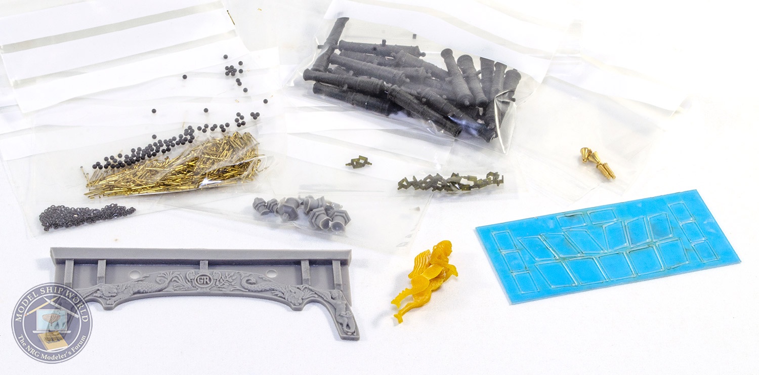
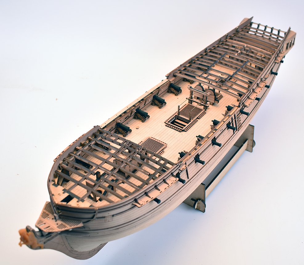
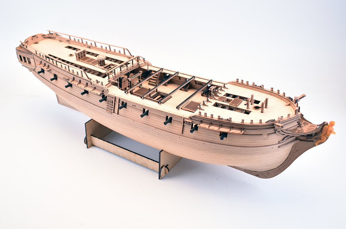
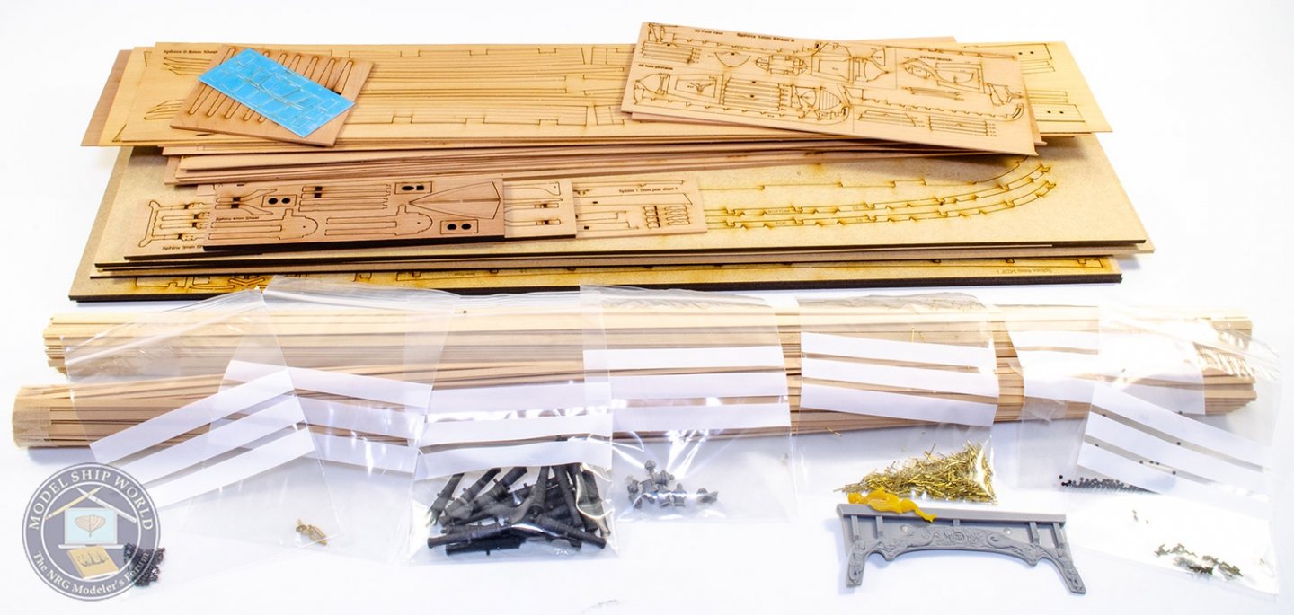
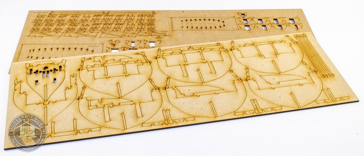
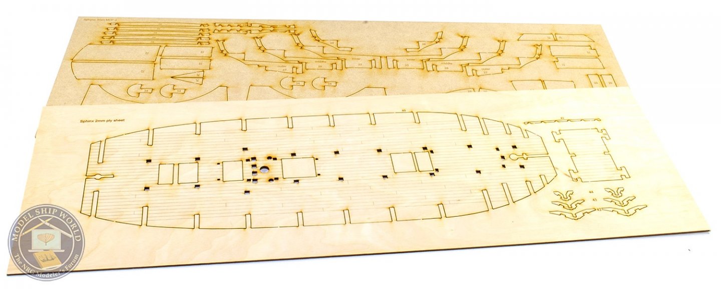
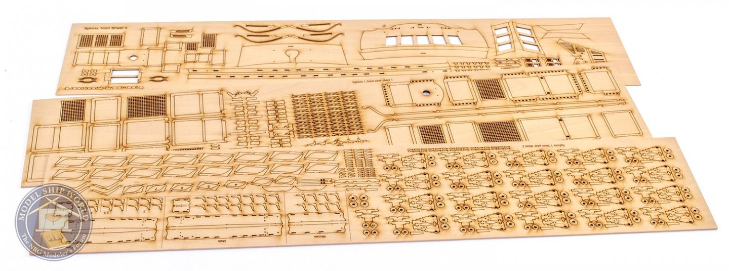
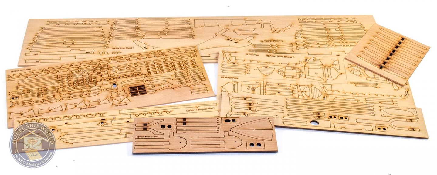
Well, my bench has been idle for long enough... HMS Sphinx is the next major release from Vanguard Models, and as per the previous 4 main kit releases and the 8 ship's boats, I'll be building up the production prototype and creating the instruction manual. Just a little 'ye potted historie' of Sphinx: She was a 20-gun sixth rate launched in 1775. Captured by the French in September 1779, she was recaptured by HMS Prosperpine on 29 November 1779. Sphinx was finally broken up in 1811. Onwards... One thing you'll note if you buy the completed kit is that there's quite a weight. Chris shipped me two complete sets of wooden parts (and some fittings), and that pack, minus any plans, heavy manual or the numerous sets of photo-etch, came in at a whopping 7kg. Factor in around half that weight, plus those missing items, and you'll see it's a bumper pack. There are over thirty sheets of laser cut material, also incorporating the three ship's boats (a good number of different thicknesses). Apart from the MDF sheets which comprise the Sphinx's skeleton, a ply sheet with the lower deck etc, laser-engraved maple decks, the rest of the material is pearwood. Two bundles of strip wood are included; the obligatory lime for first planking, and some 0.8mm thick pear for second planking. The colour is this really is very nice. There are numerous changes between the first test hull Chris built and featured on MSW, and this version, with deleted parts, new parts, and things which have been improved further to make building even more enjoyable. I now have a few days of acquainting myself with the original reference build pics before I can start this, probably this coming weekend. Cannon are in black resin and nigh on ready to use. They look really nice, and the cannon balls are in black plastic, so no painting. Boat beam brackets are in very strong resin, and there is a sheet of laser-cut acetate for the stern/quarter windows. The stern fascia is cast in resin and also looks seriously nice. The figurehead is beautifully detailed and 3D printed. Stern lanterns will be from PE and resin. The colours on this will be very similar to the Duchess of Kingston, but with red inner bulwarks. Whilst my build will be strictly 'out of box', the scope for extra detailing the cabin at the stern, will be more than a temptation for some, with that engraved, chequered floor and engraved doors to the quarter galleries. As there will undoubtedly be questions I can't answer, feel free to use this log to also ask Chris questions that are specific to this release. I'm sure he'll chime in with any extra contents details I missed here. Wish me luck ☘️


- 355 replies
-
- 50
-
-
- vanguard models
- Sphinx
- (and 1 more)
-
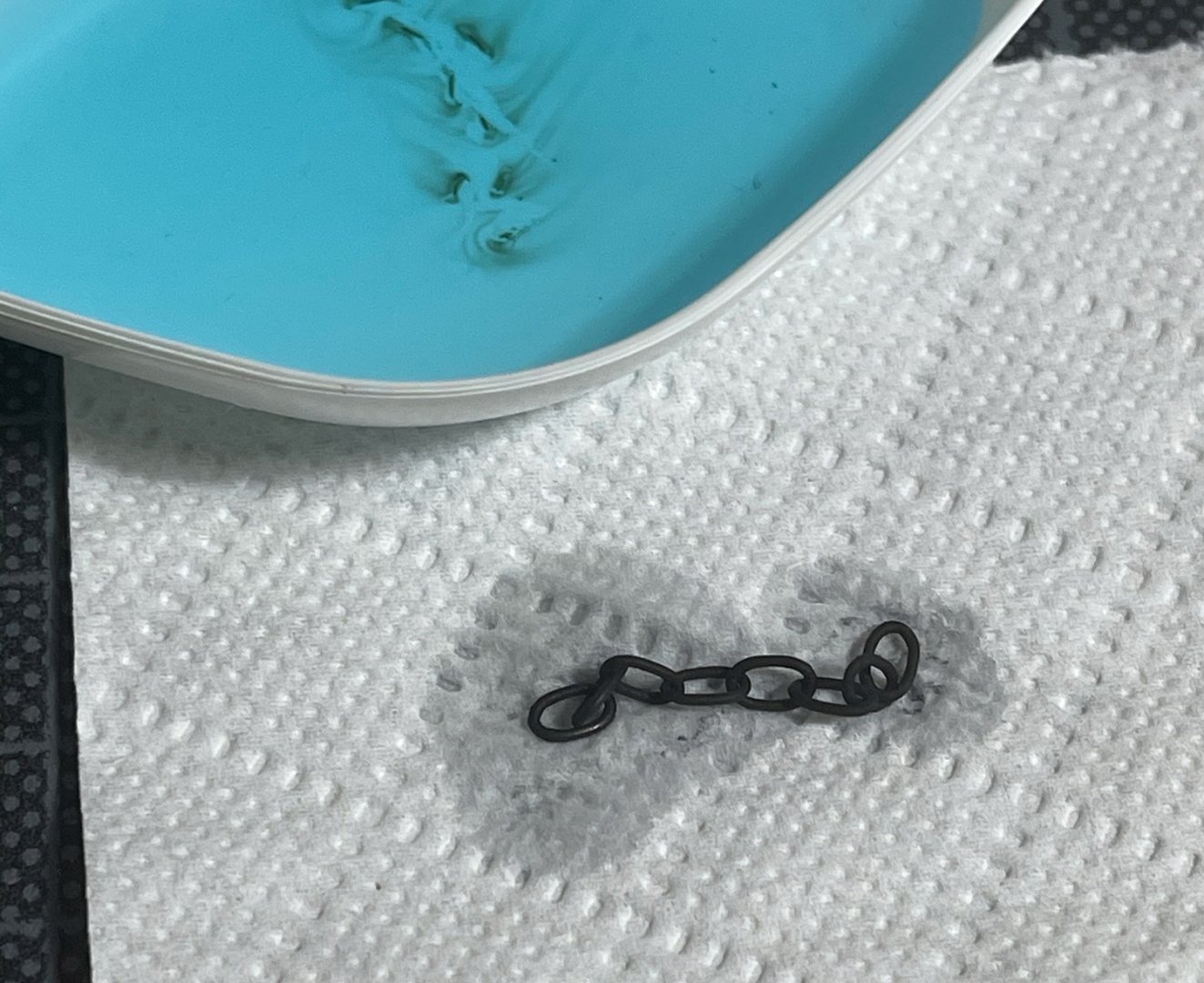
And those links also seem to be solid all round with no joint, so pulling shouldn't present a problem. To remove that section, I had to cut right through a link.
-
There you go!
-
I’ve asked, but I don’t think it’s coated, so should be easy enough to blacken. I’ll try with a test piece shortly.
-
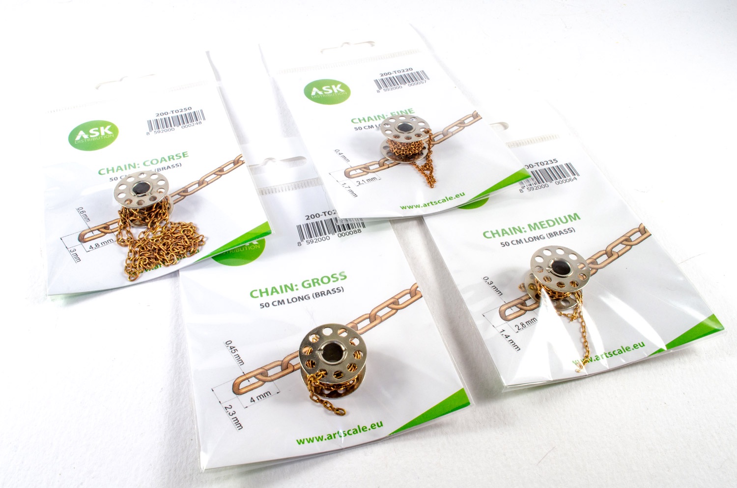
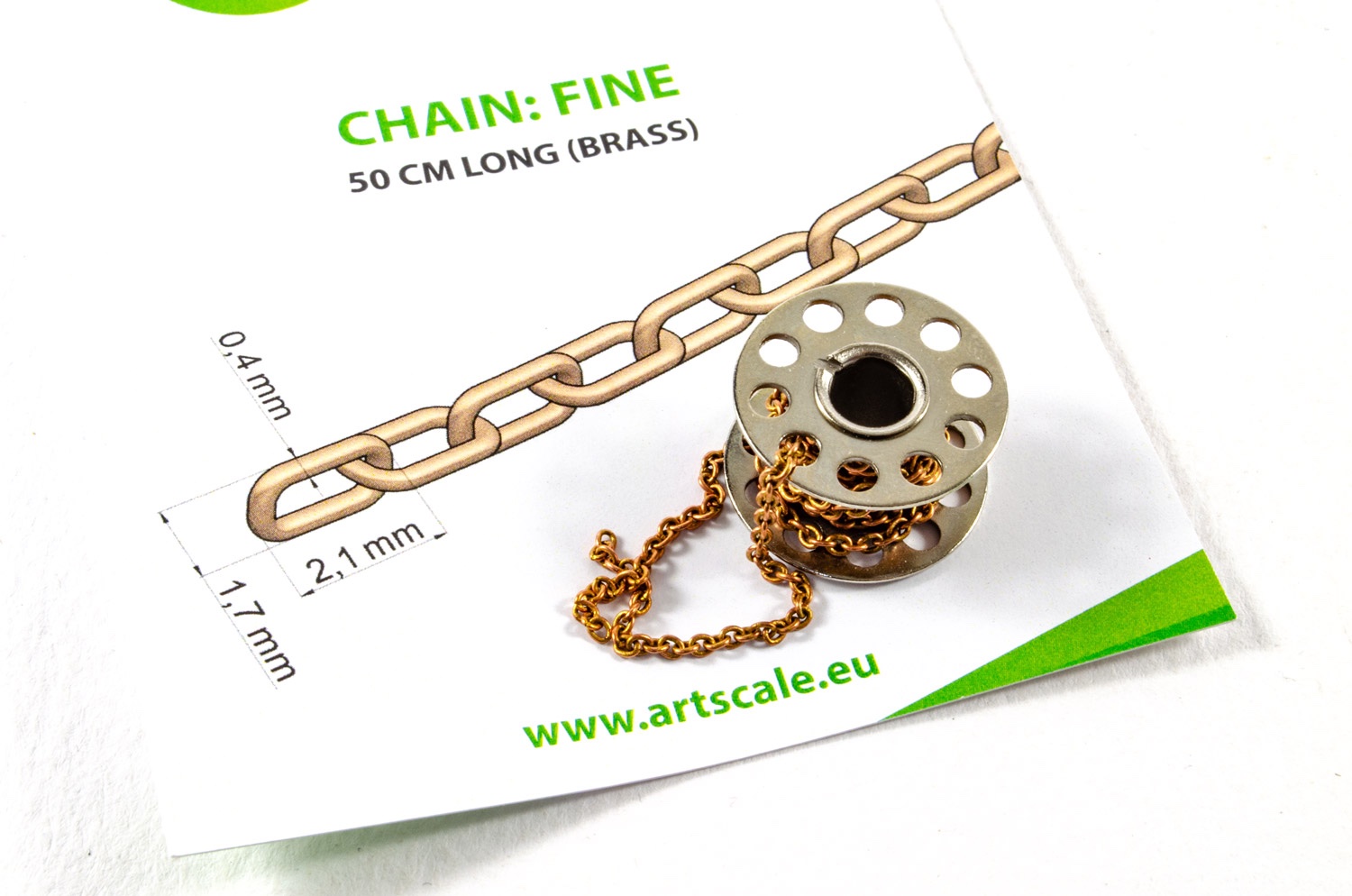
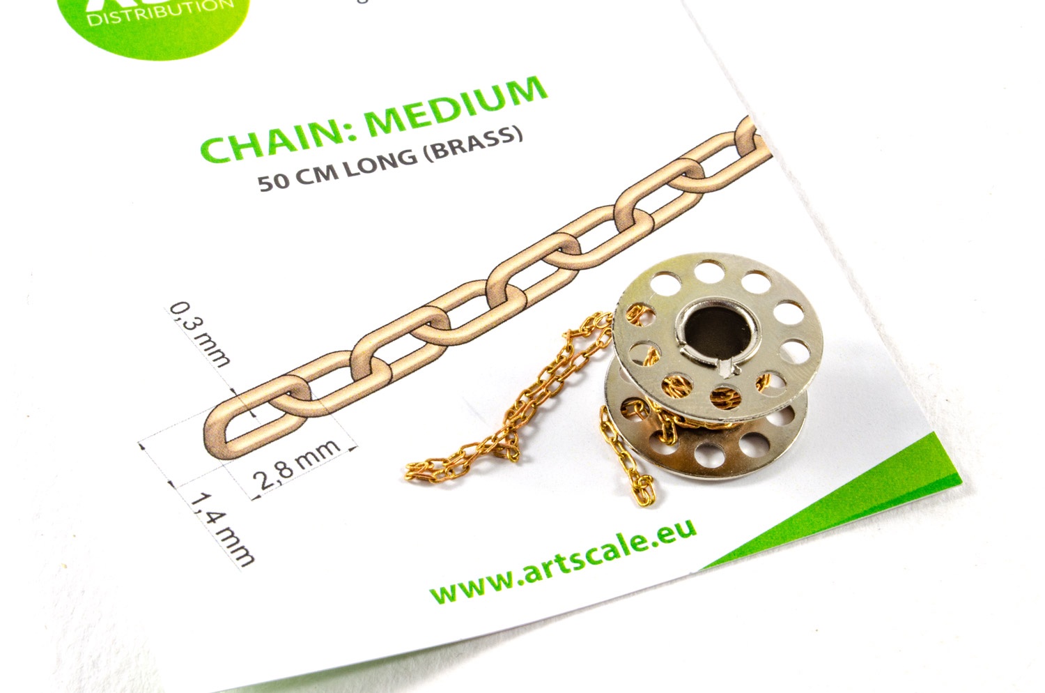
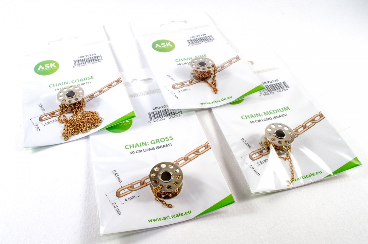
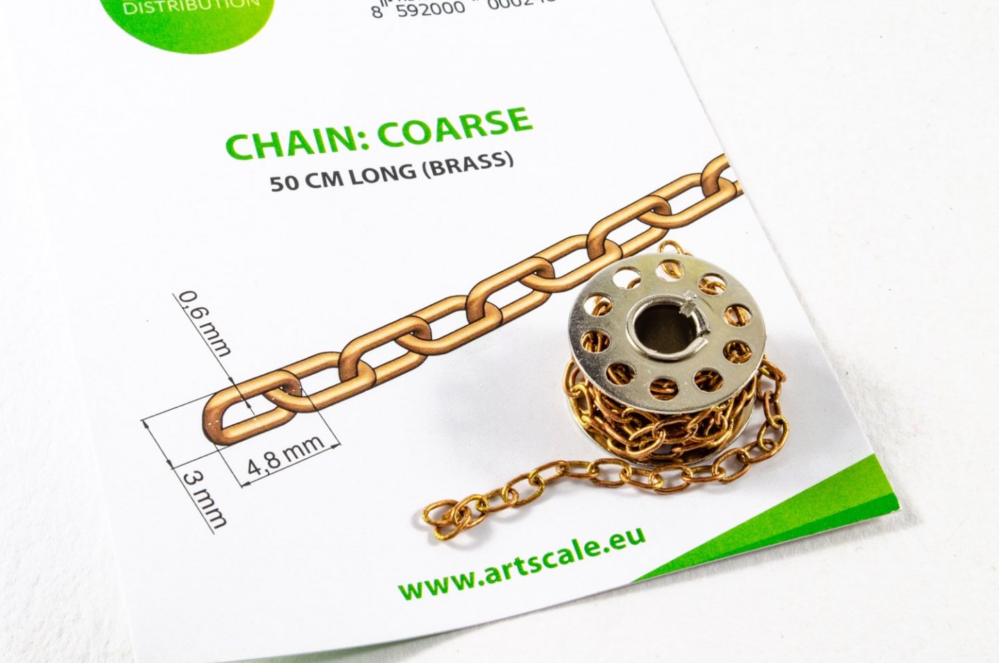
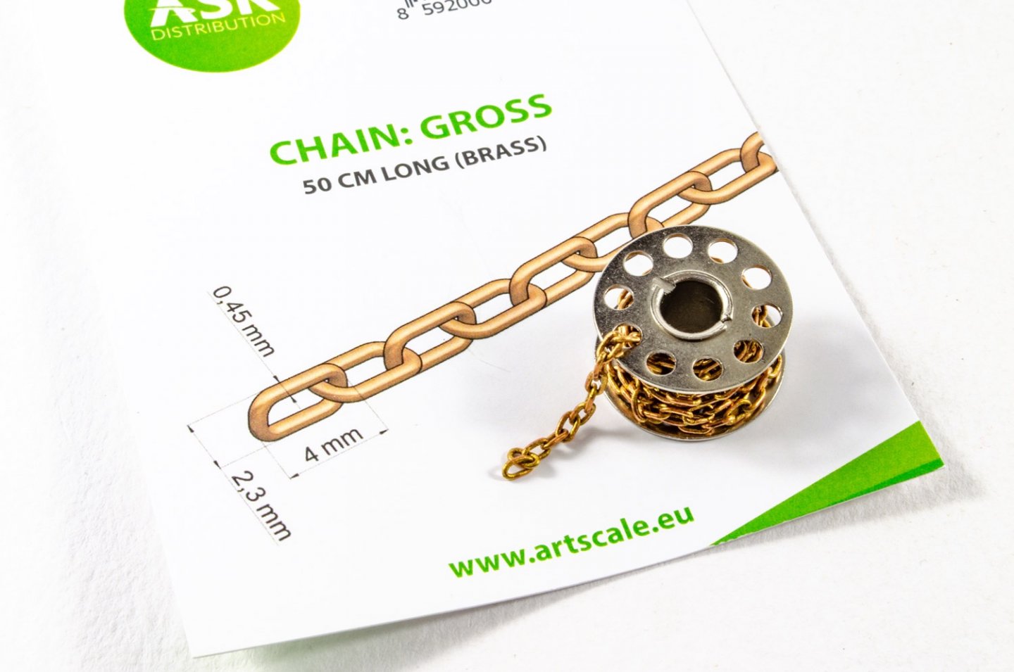
Brass chain - various sizes Artscale The good folks at Artscale have sent me a few samples of their new brass chain. The samples sent are: Gross - €3,00 Coarse - €3,00 Medium - €3,00 Fine - €3,00 All chain is provided on metal spools, in 0.5 metre lengths. Each spool is packed into a clear sleeve with a product information insert. The insert is useful as it provides dimensional detail for the chain links. It's very difficult to actually review chain, so this article serves as a guide as to the size of this product and it's suitability to your own project(s). I can tell you that the chain quality is very good and will certainly find its use in my future project work. Chain isn't something many of us actively seek out, so here's a handy article for you to bookmark, if you need to buy something specific. Check out each link for the sizes above and you'll be taken directly to the product page. My sincere thanks to Artscale for providing these samples to be published here at Model Ship World. Head over to their site for this and many other goodies (including coffee!)


-
FINISHED - 1:8 GT500 Shelby Super Snake - Agora Models
James H replied to James H's topic in Non-ship/categorised builds
Cheers guys. Of course, the Cobra is still being built in another topic, and that's now halfway through. BUT....HMS Sphinx begins this week, and that's where the lion's share of my time will be spent. -
FINISHED - 1:8 GT500 Shelby Super Snake - Agora Models
James H replied to James H's topic in Non-ship/categorised builds
STAGE 99: REAR VALANCE, FOG LIGHTS & CONNECTING THE BODY TO THE CHASSIS & STAGE 100: REAR BUMPER, FRONT & REAR LICENSE PLATES The rear valance is now fitted with fog lights. I also fit the reg plate from stage 100 too. Before the body can be fitted to the chassis, all the wiring is finally connected and batteries inserted into the engine compartment to check that all is ok. Fitting the body took me quite a bit of time in making sure all lugs and holes were in alignment, and also that all cables were safe from being trapped. That aerial is also most at risk here when you turn the car over. You might notice no rear wheels in this picture. That's because I broke the rear axle as mentioned at the start, and I decided it safest to fit the wheels last, prior to turning the car the right way round. The valence is now fitted and the number added. I also screw the front reg plate into position. All done!!!!!!!! Conclusion A lovely project that will doubtless be much loved by any petrol head or Shelby fan. The details are superb and the size of this means it's no shrinking violet. You'll need a nice care to display it, and also a strong shelf! All electronics worked as they should, from the engine sounds, to horn, rear lights and front lights. A year's worth of work is finally at an end and my bench will certainly look different with this now gone from it.- 39 replies
-
- 14
-
-
-
FINISHED - 1:8 GT500 Shelby Super Snake - Agora Models
James H replied to James H's topic in Non-ship/categorised builds
STAGE 98: SUN VISORS & REAR VIEW MIRROR The liner is now fitted with the sun shields and rear view mirror. The liner itself now just pushes into place with no problems. The aerial is perhaps the only real puzzling part for me. This should've ideally been a push fit for the last item added, but instead it needs to be screwed into the underside of the body before you can fit it, providing a hazard from this point on as you work on the model. Take care with that aerial! -
FINISHED - 1:8 GT500 Shelby Super Snake - Agora Models
James H replied to James H's topic in Non-ship/categorised builds
STAGE 97: HEADLINER Even though you get the liner, you can't fit it yet. Instead, both doors are fitted. Make sure these are nice and tight. They should also face a little resistance when pushed fully closed, giving them a positive close-fit. -
FINISHED - 1:8 GT500 Shelby Super Snake - Agora Models
James H replied to James H's topic in Non-ship/categorised builds
STAGE 96: DOOR TRIM AND SILL PLATES Those sparse door entry points need prettying up, so these trims and sills are now added. These just push into place with zero fuss on both driver and passenger side. -
FINISHED - 1:8 GT500 Shelby Super Snake - Agora Models
James H replied to James H's topic in Non-ship/categorised builds
STAGE 93: UPPER VENT GRILLE STAGE 94: REAR WINDOW The windshield wipers from the previous stage are now screwed into position on the upper vent grille, and the panel slid into place on the body, then screwed into position. STAGE 94: REAR WINDOW & STAGE 95: REAR WINDOW FRAME & RADIO ANTENNA You know the drill! Both rear window and frame fit nicely into position with ease. -
FINISHED - 1:8 GT500 Shelby Super Snake - Agora Models
James H replied to James H's topic in Non-ship/categorised builds
Pack 12 This is it folks....the final work on this behemoth, and the finished result is VERY heavy and impressive. I've had a snag along the way that delayed me posting this. When you manoeuvre your car around, DO NOT put the weight of the model on any of the back wheels. I did that and snapped the wheel fixing point of the rear axle. You live and learn, and it was so frustrating. STAGE 91: WINDSHIELD & STAGE 92: WINDSHIELD FRAME AND WIPERS Real care needs to be taken not to touch the main clear area of the windscreen, for obvious reasons. Thankfully, this just sits neatly in place with zero effort, and the windshield frame locks it into position with a few clicks.