James H
-
Posts
6,138 -
Joined
-
Last visited
Content Type
Profiles
Forums
Gallery
Events
Everything posted by James H
-
 ...........aaaaaaaaand, back to Flirt!
 -
There's no limit on logs of same subject I'd very much like to follow your progress as I did with your fisher. Sure many others would too.
-
No, but it's all very elementary ship modelling. Just sand and fair those parts until they flow correctly. You will also finalise any sanding when the hull itself is ready to be finally faired.
-
Under normal hobby circumstances, 9 - 12 months for a ship is nothing. Just take your time. Remember, I have to rush for a reason
-
After converting from RAW, the JPG (set to low compression) images were almost 6GB.
-
Always happy to help! Looking forward to your work.
-
Sorry about that. I am a plonker. It's been changed for the next print run. I was building so intensively over that period that my recollections were clouded with some of the fisher stuff I'd just finished. You can use my photos as a guide though as you're always best taking off too little than too much. It's only a rough bevel.
- 109 replies
-
- 2
-

-
- Vanguard Models
- Flirt
- (and 1 more)
-
You're gonna need it! @chris watton told me the printer says that a complete set of plans and manual alone will be 1.7kg 😱
-
Ok, the HMS Sphinx Manual is now available for download. About 950 photos. This has been intense! https://vanguardmodels.co.uk/product/hms-sphinx-1775/

-
In a week, and the 35 available Sphinx for pre-order are now down to EIGHT LEFT!!! 😁 Incredible!
-
I've been in touch with Amati's boss man, and I can tell you that after Italy's August hols, that Victory part production should be starting again.
-
I presume you are UK (your email addy), so if the Modeler's Central is the Aussie one, that could be a reason? I presume shipping costs and distribution will affect overall price at various global retailers. Plus if you are UK, CMB is the obvious choice to purchase from.
-
That looks ok to me! Don't beat yourself up. When sanded, you'll have a nice surface to add the second layer.
-
Welcome back to the hobby, and of course to MSW 😁
-
Glad that worked for you. Had loads of probs in past with stuff remaining tacky for a while but thankfully a little white spirit always relieves the pain 😁
-
Not at all. It's aimed at a total beginner, as is the Fifie Welcome to MSW!
-
Is the timber walnut? I know when I add poly varnish, it can take 2 or 3 days to fully dry as it the walnut seems impervious. Maybe leave it another 48hrs and see. You could use some rag dampened with white spirit and gently wipe them down, then leave for a while.
-
As it says, if you have anything useful to our community, both to laser cut or 3D-print, add it to this topic and I'll add to this initial post
-
- 2
-
-
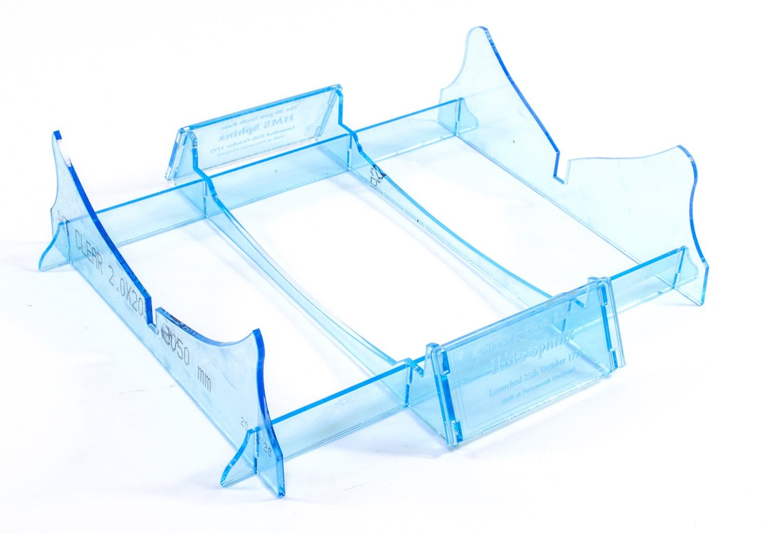
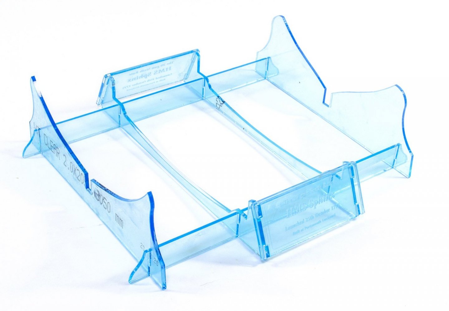
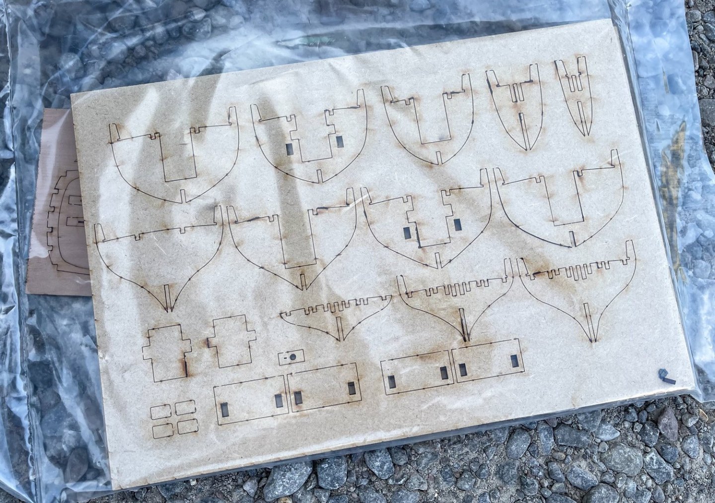
Way too much rich food, so I need to trim down a little. With regards to the Sphinx stand, this is the one supplied. I left the blue film on for assembly shots, but there will be pics of it without that film when done.
-
Such a shame, but if something is sapping your enthusiasm, then shelve it until you feel differently, and then maybe use as a filler project between others. Perhaps after Badger, maybe the Sphinx kit? (no, I'm not on commission earnings! 😂)
-
Yes, fully masted and rigged as per other VM kits. I'm fresh back from hols only 2hrs ago and already working on the prototype again.
-
Ooh, what's this?
-
I built that 1:72 Matchbox kit about 20yrs ago as a prelude to starting wooden ships, and I loved it. Amazing to see something in 1:48 like this.
- 321 replies
-
- 7
-
-
- Finished
- Flower-class
- (and 1 more)
-
I only wish. I'm now on starting Sphinx shroud pendants and my room is blistering hot. It's almost unworkable for I need to stay in there for as long as I can before it makes me feel drained and sick.
-
NEW AT VANGUARD MODELS! - 'BUY NOW, PAY LATER' (Pay In Three) from PayPal. I've been helping Chris with his website and PayPal have really been bugging us with rolling out this system for VM customers. VM satisfies their criteria which allows customers to make purchases from £30 to £2000 using a three-payment system. Once you go to PayPal checkout, you will have an option to choose this. The total cost is split into three equal payments at 0% interest, and then the remainder is paid on the due dates over the following two months. The great news is you of course get your items shipped straight away as you would if you'd paid up-front. That'll help break up some of those costs we all have when it comes to buying our kits and stuff! https://vanguardmodels.co.uk https://www.paypal.com/uk/webapps/mpp/paypal-payin3/faq There are some territory restrictions, but can't remember them at moment!