James H
-
Posts
6,139 -
Joined
-
Last visited
Content Type
Profiles
Forums
Gallery
Events
Everything posted by James H
-
 Everyone who has just announced the happy arrival of their newborn Sphinx, please open a build log. We want to see them all of course, but it will save B.E.'s log from being overwhelmed with your news.
- 857 replies
-
- 6
-

-

-
- Sphinx
- Vanguard Models
- (and 1 more)
-
Can't wait to see this one on here tomorrow when UPS bring that heavy box
-
Hi Chuck, A big welcome to MSW. Nice to chat with you via email earlier
-
Hi Zoran, I don't see any posts by any MSW moderator on this topic. How did this happen, and where? Why would people wish to devalue your work on this project? There's no doubt that MarisStella have some amazing and amazingly beautiful ships/products in their range, and many fine vessels I would one day to like to try. Without derailing this build log, here is a review of one such kit:
-
So, have you got it yet? 😜
-
Sorry, no...I DO mean their Flat Red. The two bottles I have aren't even close to the same colour, and the later one is really oily and bad to paint. Maybe they changed the formula or this is a bad production run.

- 857 replies
-
- 3
-
-
- Sphinx
- Vanguard Models
- (and 1 more)
-
Be careful of Vallejo Red. I have two bottles here of the same catalogue number, and they are very different. The older one paints dead easy and is quite vibrant. The newer one looks 'dirtier' and doesn't paint anywhere near as easily with a brush.
- 857 replies
-
- 3
-
-
- Sphinx
- Vanguard Models
- (and 1 more)
-
A quick heads-up... As the printers included an extra set of plans and manual (zero idea why!!), there is ONE more HMS Sphinx in the store. https://vanguardmodels.co.uk/product/hms-sphinx-1775/ No further kits can be made up until the next PS comes from Italy some time next month. I'm sure Chris won't mind me letting you all know
-
Yes, it comes with masting and rigging. See post #285 above. And the masting pics in this build log.

- 355 replies
-
- 7
-
-
- vanguard models
- Sphinx
- (and 1 more)
-
As soon as it's fully rigged, yes...definitely. It's full steam ahead now so Chris can add that stuff to the Rev.2 instruction manual for next batch of kits. The rig stuff isn't really needed for the manual as that's usually all done via plans anyway, but it's nice to add some of it to the next updated manual.
- 355 replies
-
- 10
-
-
- vanguard models
- Sphinx
- (and 1 more)
-
That now looks perfect for second layer.
-
Feature Suggestion
James H replied to CDR_Ret's topic in Using the MSW forum - **NO MODELING CONTENT IN THIS SUB-FORUM**
I'm sort of with you and what you mean, however, we don't write the software and are bound by any limitations. -
That's the layout format. Turn your phone sideways and it should reappear.
-
There is a refresh on the site for recent topics/who is browsing etc. That's put in place simply because of the sheer size of MSW. Each time information is displayed, a query is made on our database, which is huge. The system tends to generate information on activity every 5 mins or so, to stop the site from crawling to a halt.
-
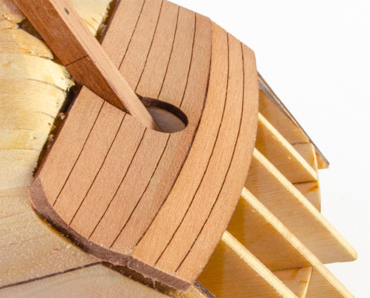
You really needed to bend those first planks inwards to tuck in under the stern counter area, like this: I would look at adding some scrap timber/block in where those planks are cut short, then shape them in so there's a curve towards the counter...taking into account that you will have a second layer that will fit more or less flush with the counter itself, when complete.

-
Feature Suggestion
James H replied to CDR_Ret's topic in Using the MSW forum - **NO MODELING CONTENT IN THIS SUB-FORUM**
Hi Terry, The Gallery does have arrows to click for next and previous image. They appear when you move cursor over picture. You can see here:
-
I think MDF has run its course here folks, plus this is still a build log
- 355 replies
-
- 15
-
-
- vanguard models
- Sphinx
- (and 1 more)
-
I'm the same with main stuff. I sit on a bench in front of the house and just sand away!
- 355 replies
-
- 4
-
-
- vanguard models
- Sphinx
- (and 1 more)
-
Suffice to say that many wood dusts are classed as carcinogens, and with ply, you can add the bonding resin to that, which isn't water soluble. Anyway......we don't have a great track record on MSW for debating MDF, so let's close that subject.
- 355 replies
-
- 7
-
-
-
- vanguard models
- Sphinx
- (and 1 more)
-
Will do. I did almost miss this post so if anyone wants me to sort this for them, please PM me.
-
Whether I'm sanding wood or MDF, I wear a mask. Both aren't good for you in the slightest. I've never experienced any problems in strength when it comes to sanding. Of course, if a piece looks more fragile, then just be cautious. The stuff used is high grade as I'm sure @chris watton will attest to. You certainly don't need to coat it in anything to strengthen it, hence no reason to mention it. Paranoid? 😆 Possibly!
- 355 replies
-
- 3
-
-
- vanguard models
- Sphinx
- (and 1 more)
-
Disgraceful! Was the Playstation 5 not enough? 😆 ...of which there are only FOUR kits left of this initial run. Get 'em while you can 😜 If you want an idea about the kit, check out the instruction manual: https://vanguardmodels.co.uk/product/hms-sphinx-1775/
-
This was a nice build and easy to plank. Watching along 🤩
-
Really looking forward to seeing you tackle the intricacies of this one.