


thibaultron
-
Posts
2,876 -
Joined
-
Last visited
Content Type
Profiles
Forums
Gallery
Events
Posts posted by thibaultron
-
-
Part 025 – The Vacuum System! Finally!
I bought some 1 ¼” OD Vacuum hose on-line. Fail, the hose had 1/8” thick walls, and while vinyl was way too stiff!
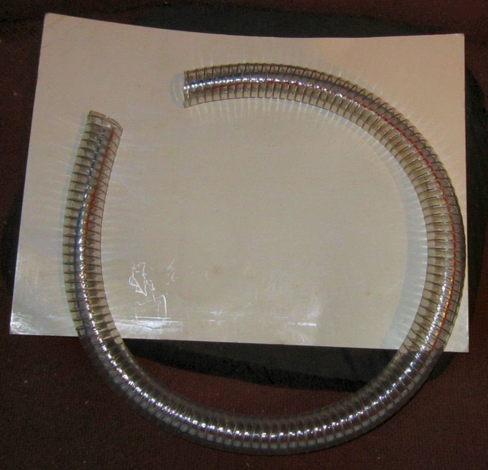
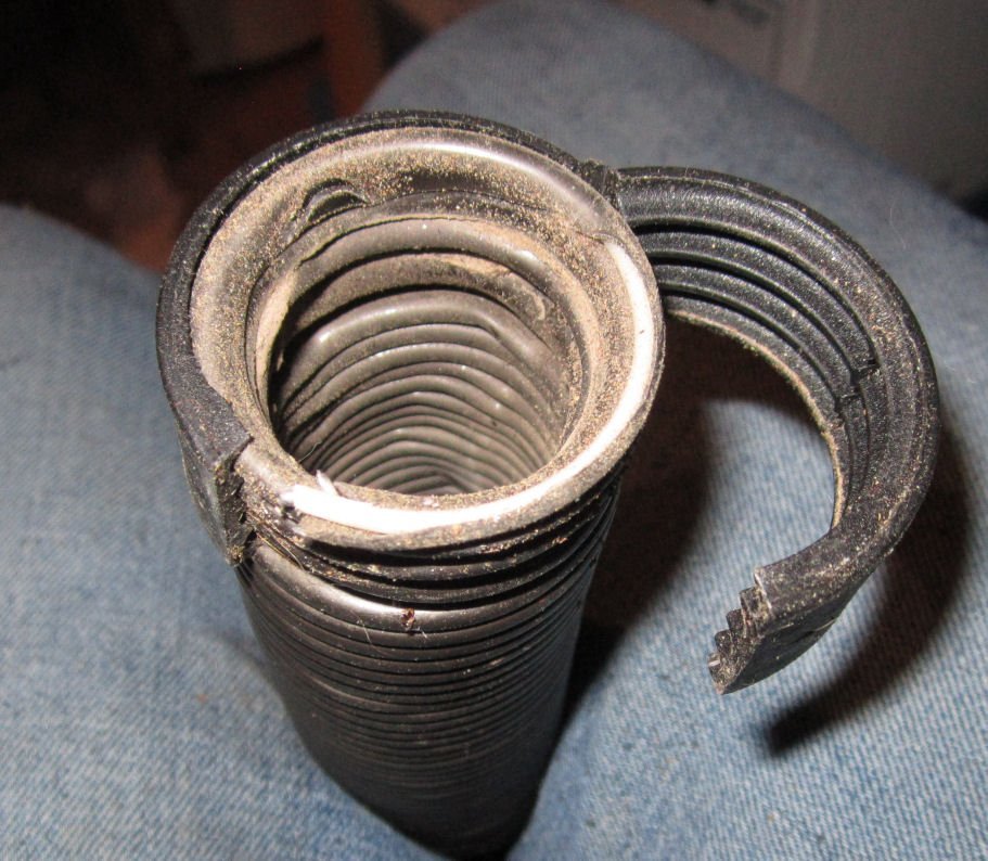
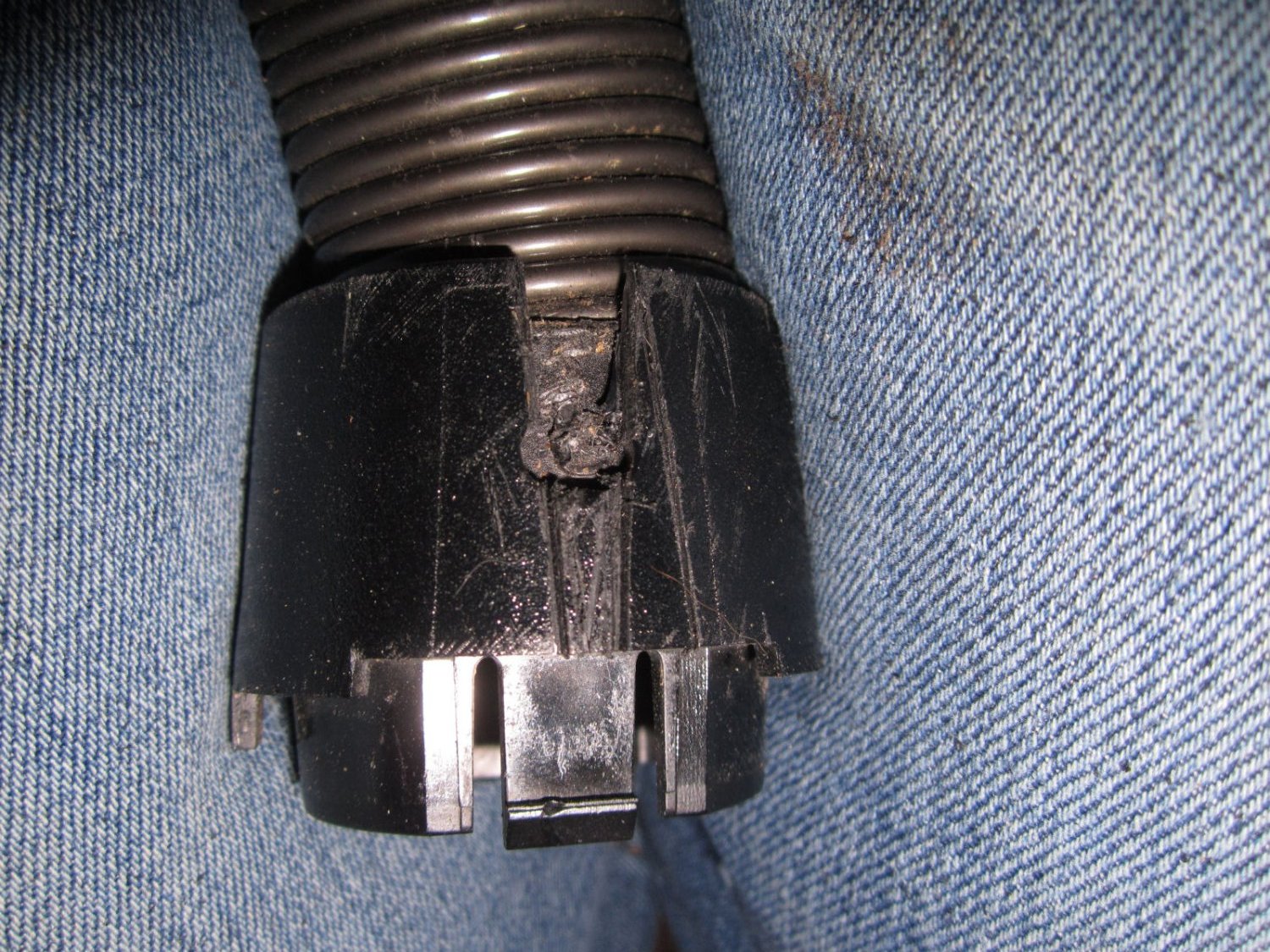
Our upright vacuum did not have much suction, so I convinced my wife to let me scavenge the hose from it. After much work, and some breaking of parts, I managed to separate the hose from the base. The wand end was too long to fit inside the enclosure, and the other end had a large fitting on it. I had to cut two slots in both fittings to free the two pins locking the hose to the fittings.
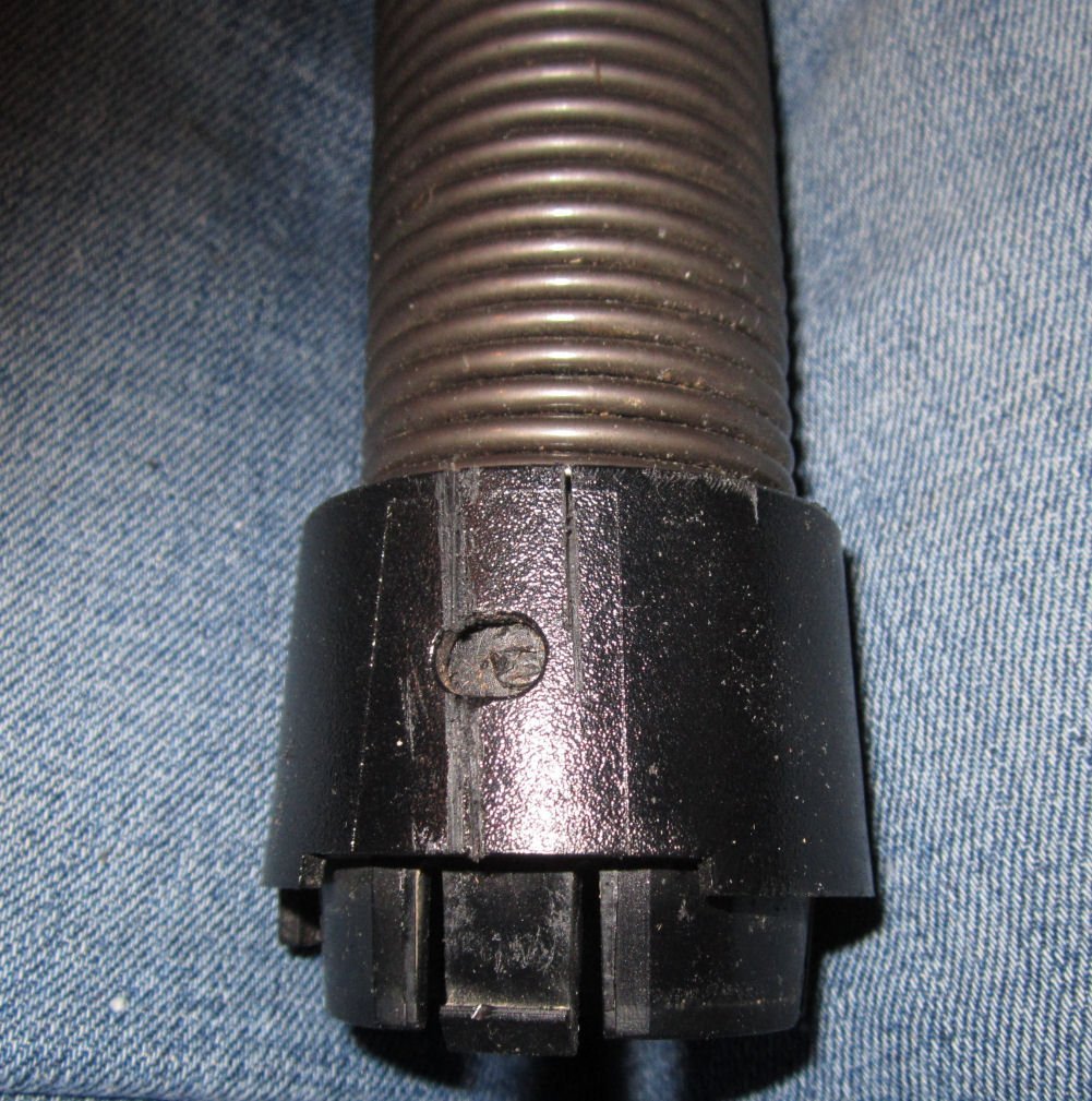

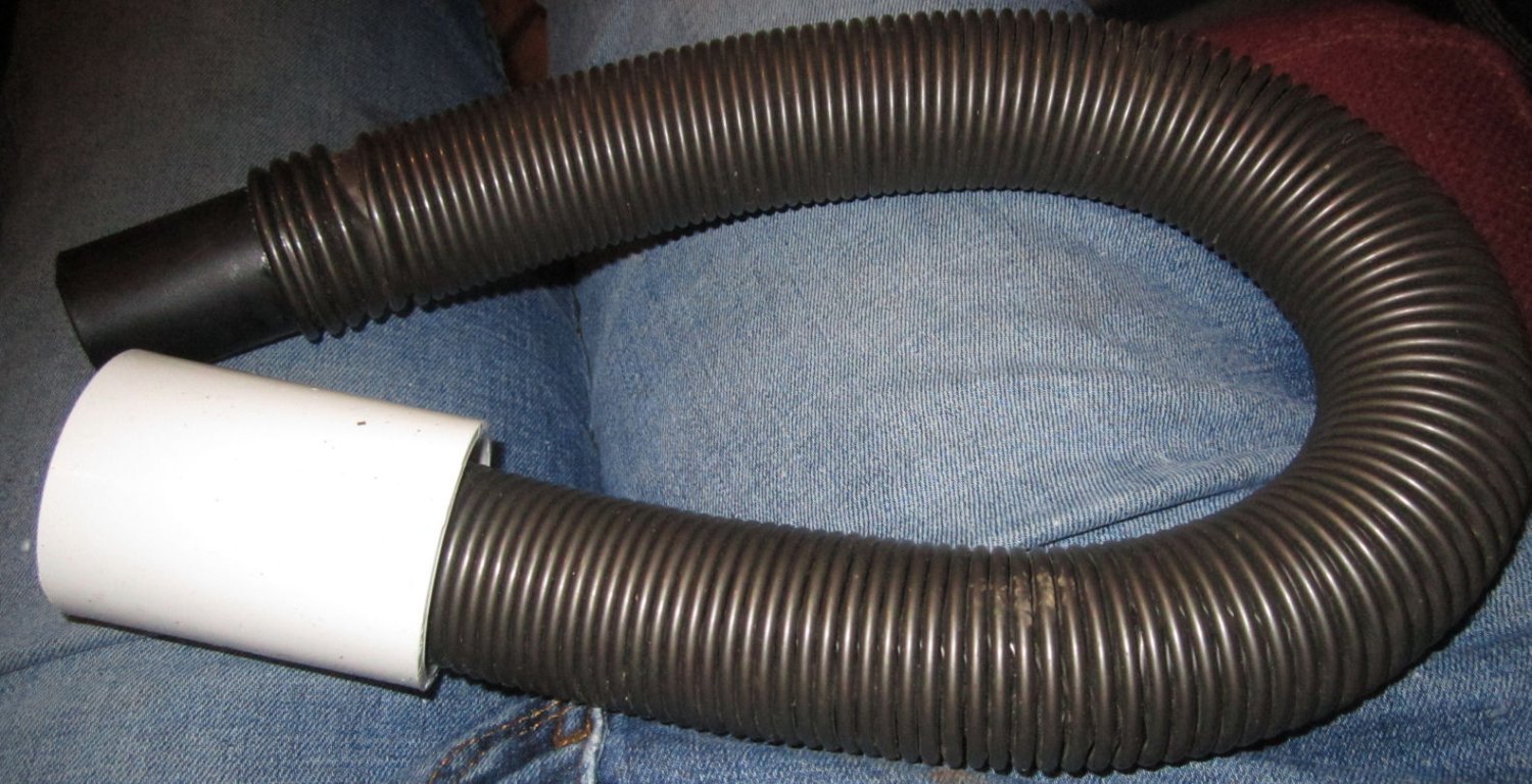
This left me with the hose with a removable hinged clamp on each end.
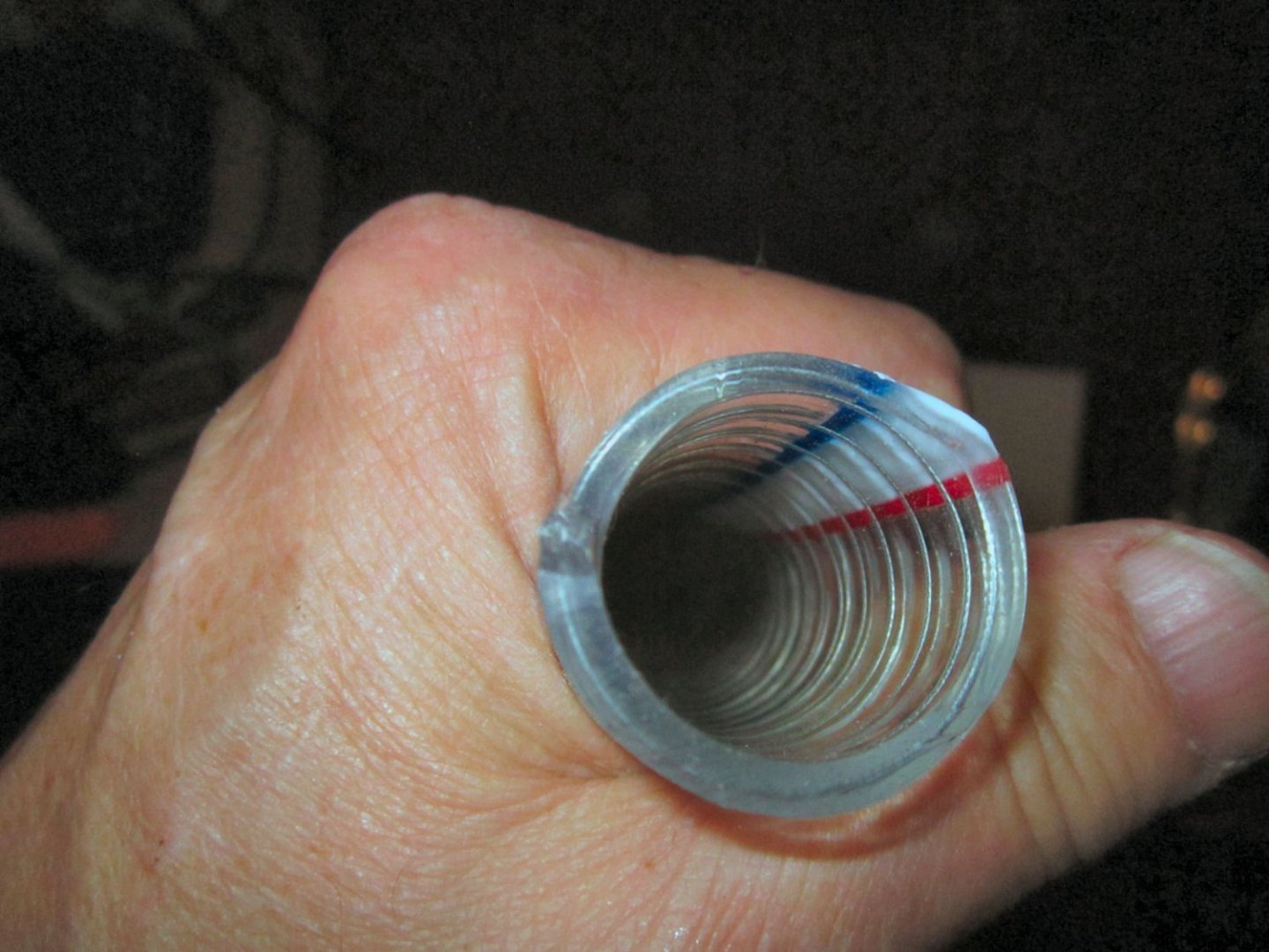
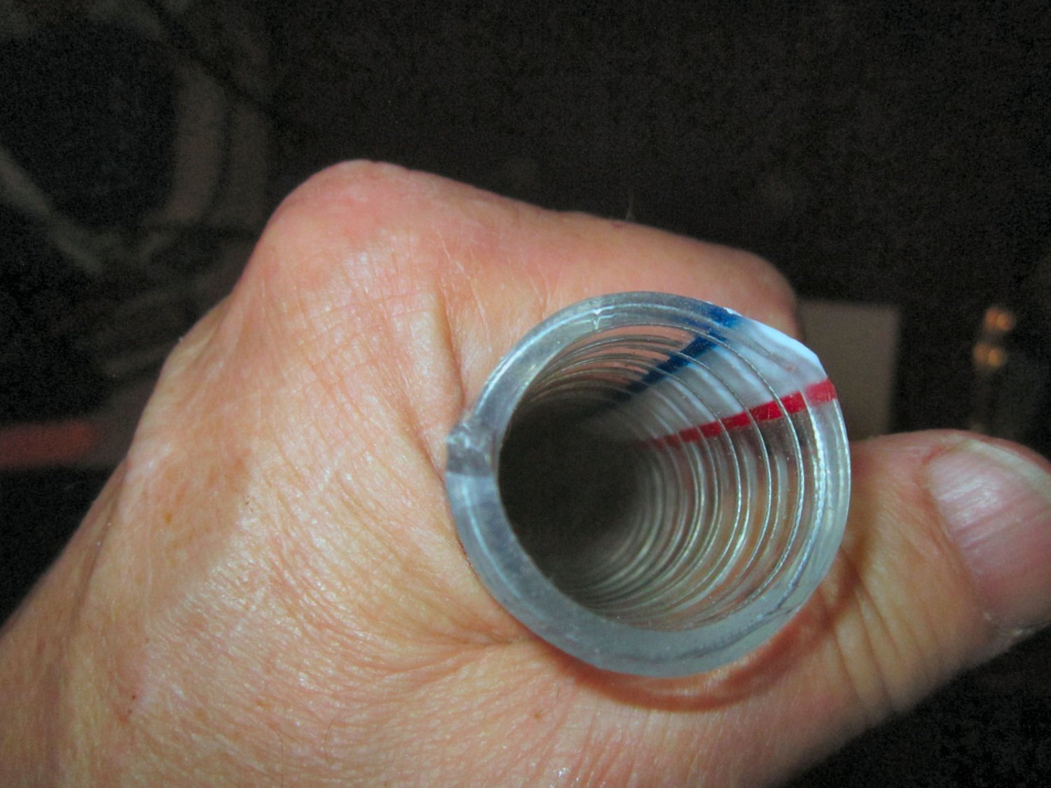
Now the fun began! The hose was 1 ¼” ID, so it would not fit in or over the dust shoe connector, which is setup for either 1 ¼” OD or 1 ½” ID hose. I sacrificed one of the straight hose sections on my shop vacuum (1 ¼” OD) and forced the tip section into one end of the hose. There was not room to use the clamp, so I wicked in thin CA to glue the tip in place.
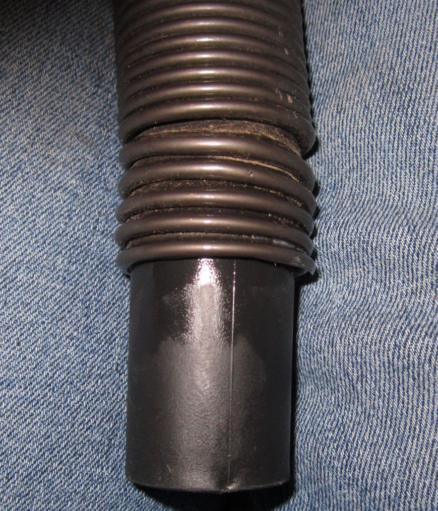
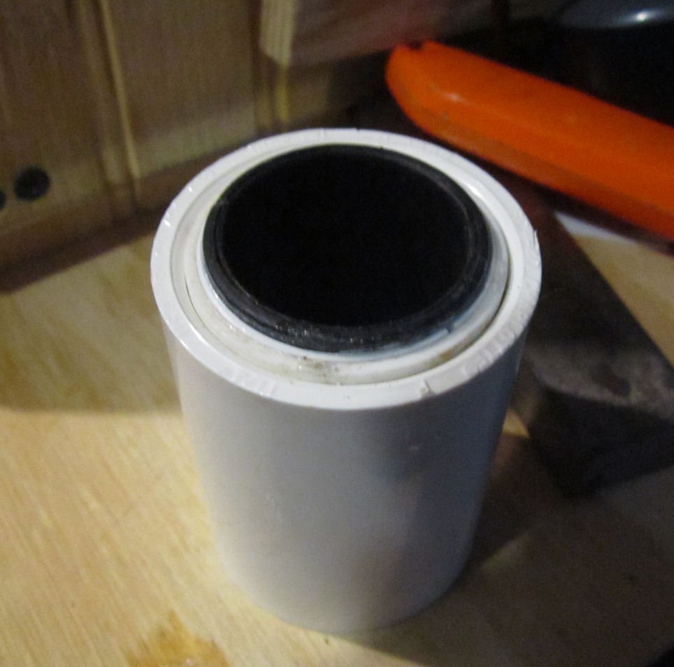
The other end of the hose with the clamp attached just pushed tightly into a 1 ¼” PVC water pipe coupler (the coupler is a little over 1 ½” ID). The coupler keeps the clamp pressed tightly closed.
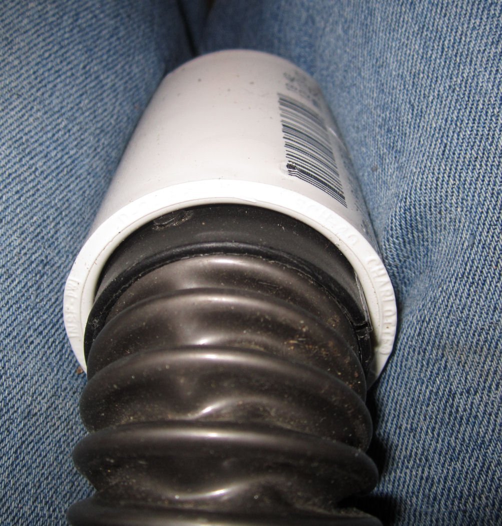
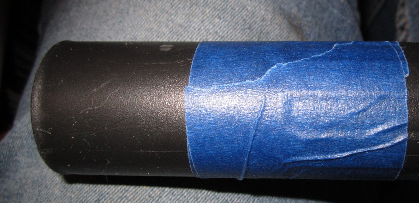
Then the next problem came up. I had purchased a length of 1 ¼” PVC pipe, figuring that the shop vacuum tip that fit nicely into the 1 ¼” ID dust shoe hole, would also fit nicely into the 1 ¼” ID pipe. Nope! The pipe is actually about 0.010” smaller in diameter than the 1 ¼” nominal size! Looking around I still had the rest of that straight shop vacuum section, with the flared end that, naturally, did fit the flexible shop vacuum hose, and a section of 1 ¼” thin wall pipe (this has a wall thickness about ½ that of the standard pipe). The thin wall pipe fits the coupler, but the flared section was slightly smaller than the ID of this pipe. So I had to fill in the gap. I cut the flare off, using a piece of tape to guide the cut.
Then I cut a strip of 0.40” styrene to fit inside the thinwall section. I used a heat gun to soften the strip, so I could bend it to fit.
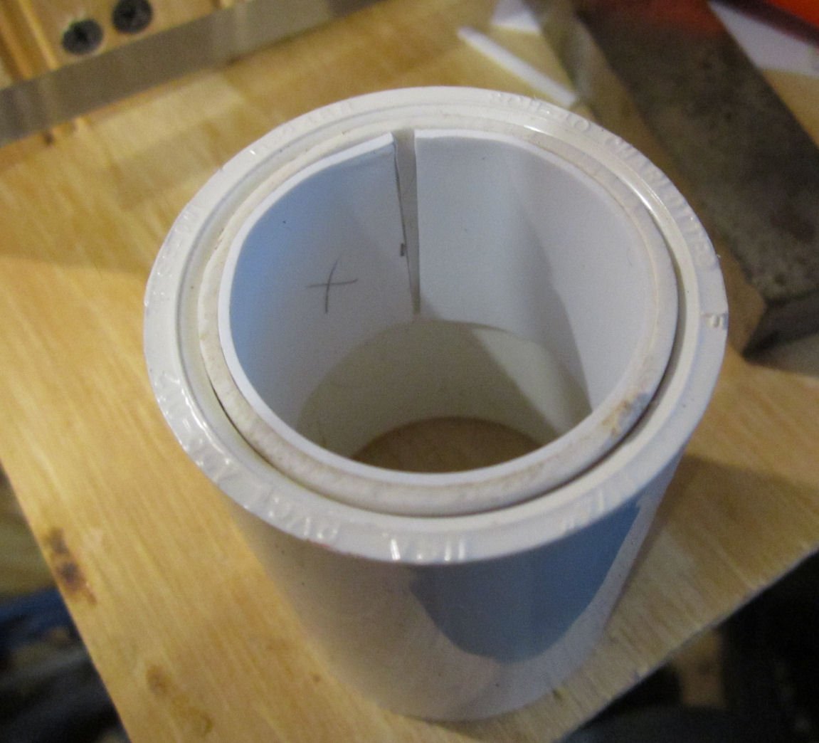
Now the flair fit with a light push fit.
I use thin CA to wick into the joints between the parts. When that had hardened, I ran a bead of thick CA to seal both the exposed end, and along the inside seam, to seal the gaps. Now I had a strong connection for the shop vacuum hose, and a removable tight sliding fit to the other vacuum’s hose on the opposite end of the coupling.
I cut new centering jigs to fit the OD of the coupler, and used them to position the outer cutting guide on the enclosure.
I positioned it near the top front of the left side of the enclosure, as this was in line with the dust shoe fitting, thus keeping it away from the X/Z-Axis assembly. I once again used my Dremel with the router attachment, and a 1/8” SainSmart bit to cut the hole.
To determine the proper length for the internal hose, I set the spindle to the Home position, and using a spare 1 ¼” coupling I put the tip into the dust shoe, and fed the hose through the coupler. I tried various lengths, until the hose was just stretched when the spindle was Homed, but not laying on the bed when it was at the far left of the machine. I marked it and cut down the hose.
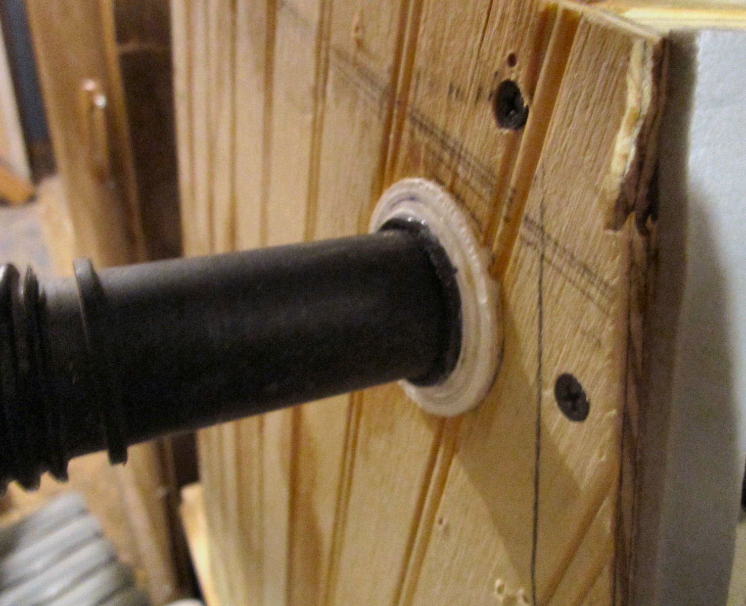
The fit between the modified coupler and the enclosure was tight, so I forced it in until the end was flush with the outside of the wall, and used thin CA to wick in, and glue it in place.
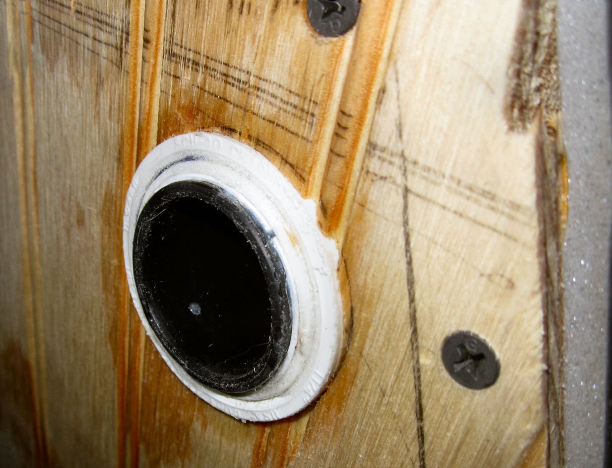
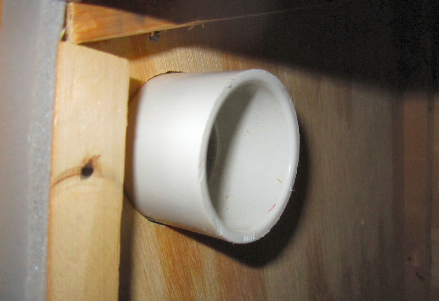
This left the rest of the coupler inside, to add some horizontal support for the hose.
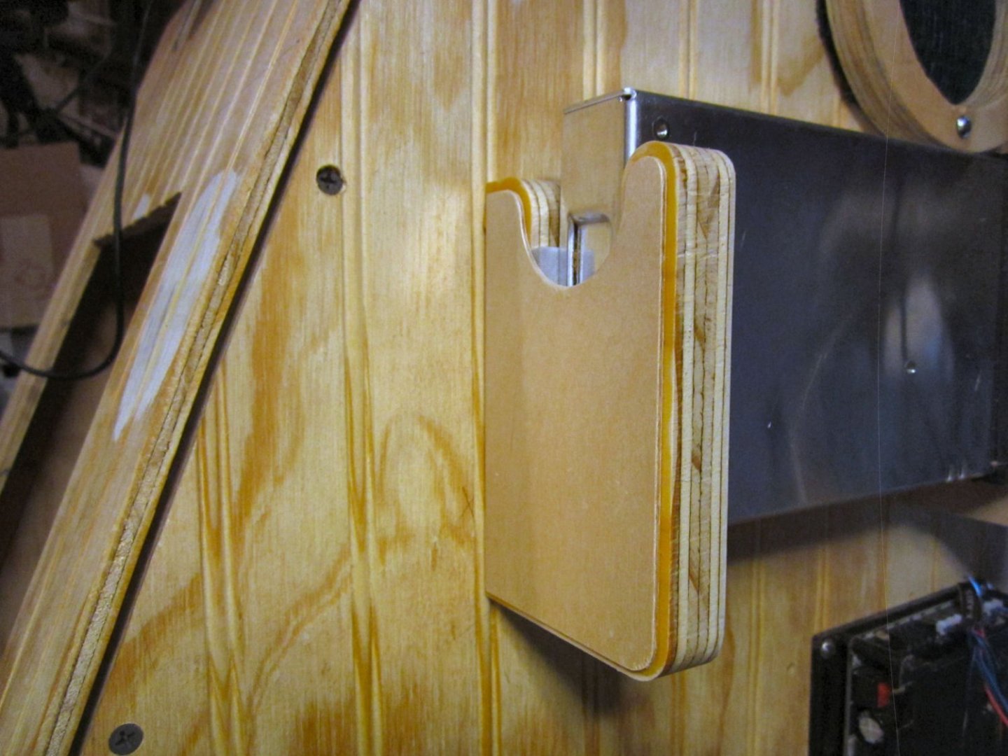
This is a picture of the shop vacuum hose fitted to the outside.
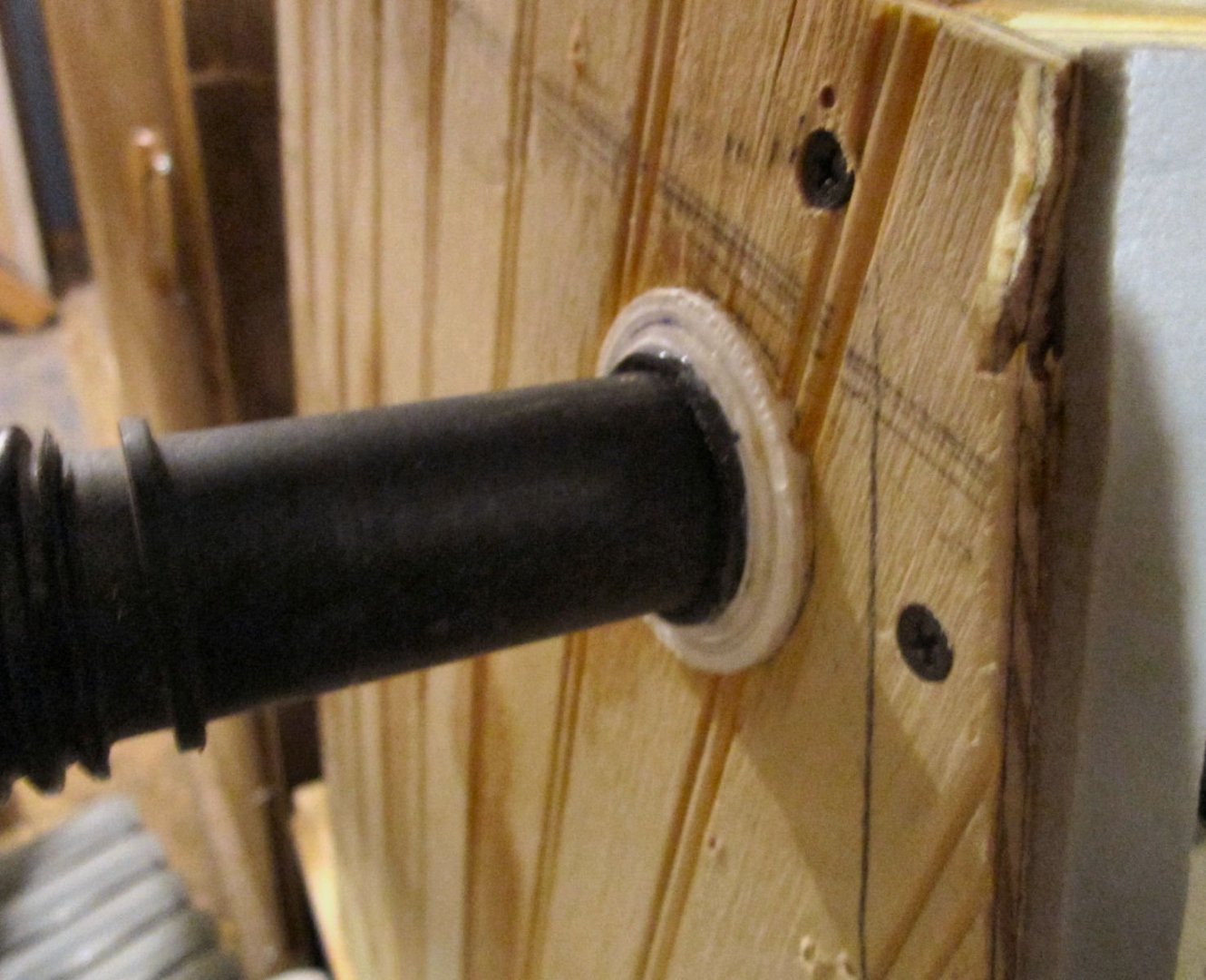
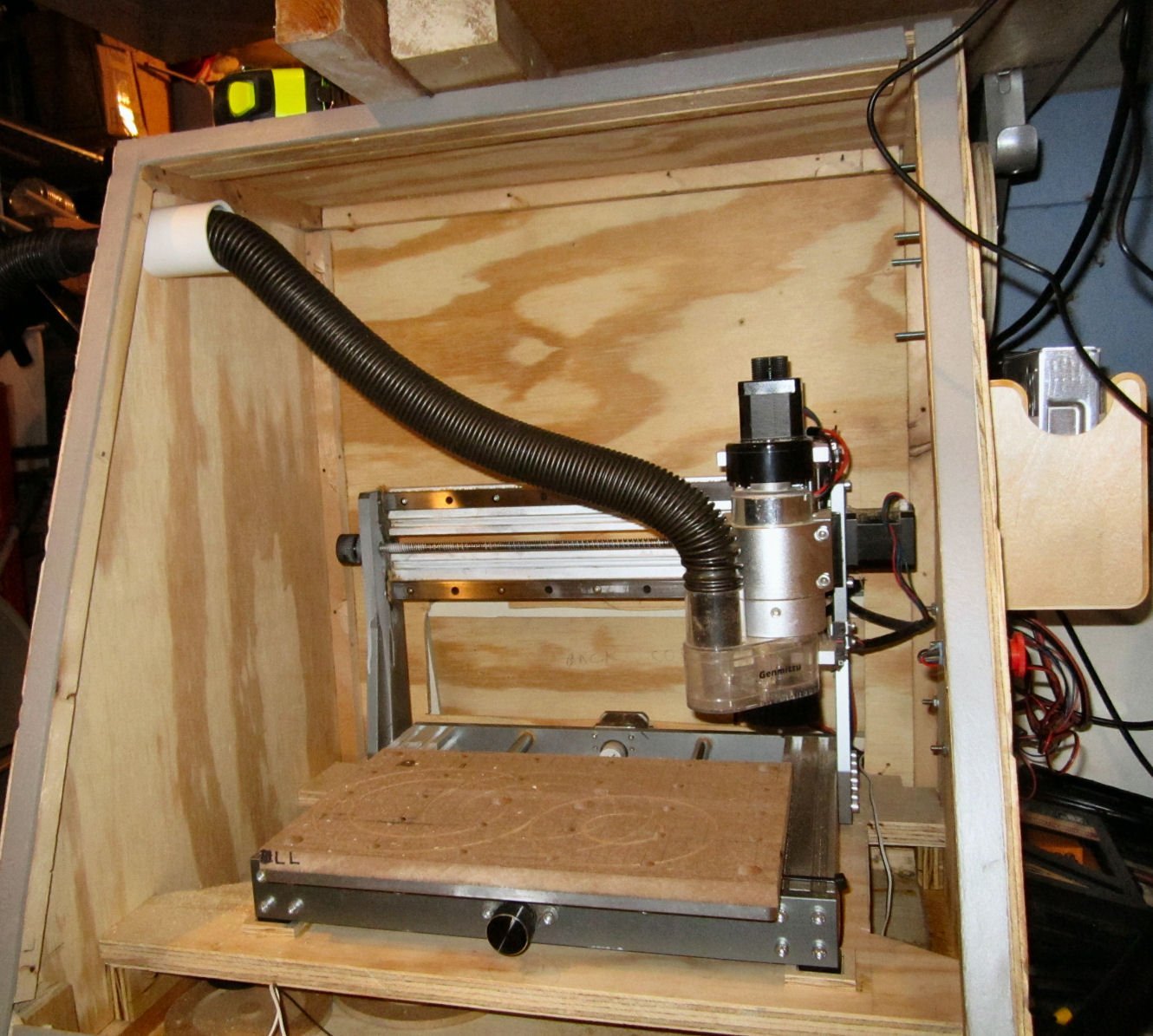
Here is a picture of the finished vacuum assembly.

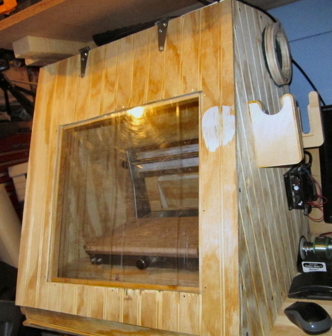
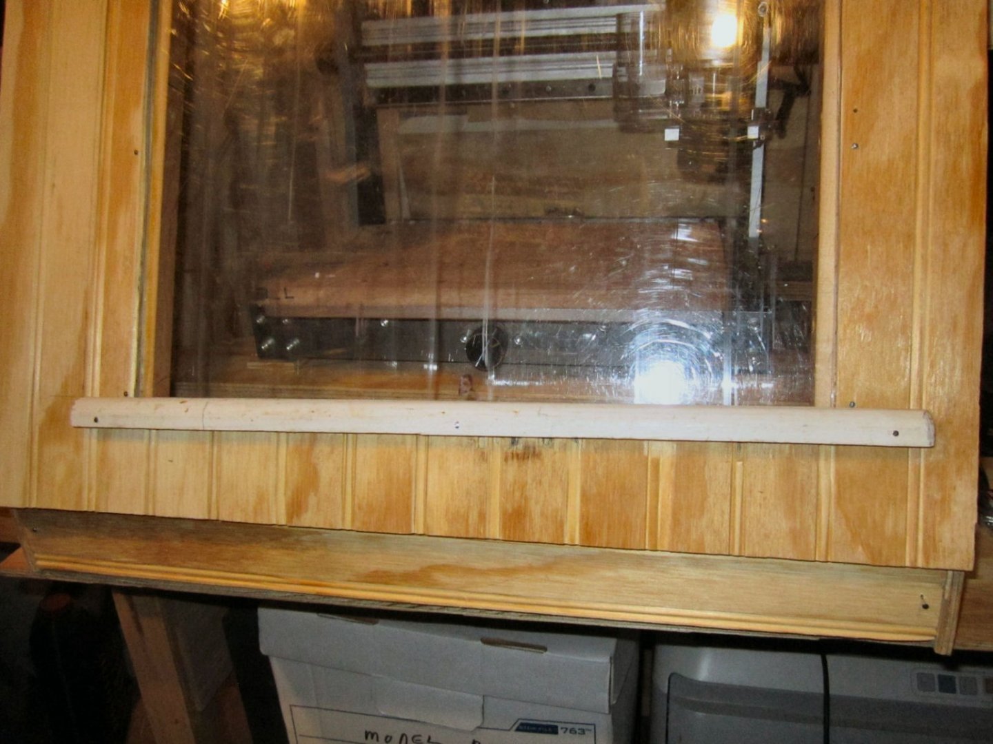
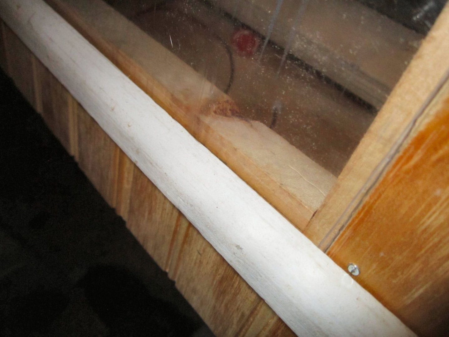
With the vacuum assembly completed, I was able to reinstalled the door and the window, and the enclosure is finished, for now. I may install a pulley system to raise the enclosure up off the bench, with a removable shelf section to support it when raised, but I have not decided yet. I also need to add interior lighting.
I also have to install some sort of support for the door when it is open, and magnetic fasteners to hold the front and back doors down on the weather stripping. I may also mount a computer style 120 Volt fan over the inlet filter, to insure cooling air for the spindle, when I’m not using the vacuum.
There is enough room in the front to store the boxes I have that hold the bits, and other relevant stuff, when the router is not in use.

-
-
Well, "I pulled the trigger" and ordered an AnyCubic 4K 3D resin printer! I have a question about ventilation for it. I know it needs to be used in a "Well ventilated area", which my shop is not. The shop is well sealed, as I have to use electric heaters, and window AC units, so I can't afford to be pulling in a lot of different temperature outside air in.
My question is can I put in an enclosed air system in, using outside air just to an enclosure that is then vented back outside? Is the resin greatly affected by varying air temperatures, and humidity? I'm thinking an enclosure for the printer, a hose from outside air for the inlet, and a hose to the outside for discharge, with a 120 Volt 4" computer type fan at the discharge end to pull air through the system.
-
Part 024 – The E-Stop Wire Plug, Continued
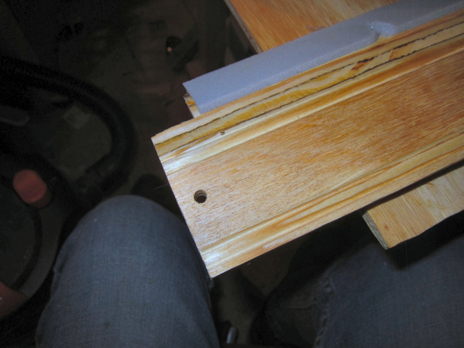
In the last part, I showed my failed attempt to cut out a plug for the hole I ran the E-Stop Button wires out.
The design.

The first results.

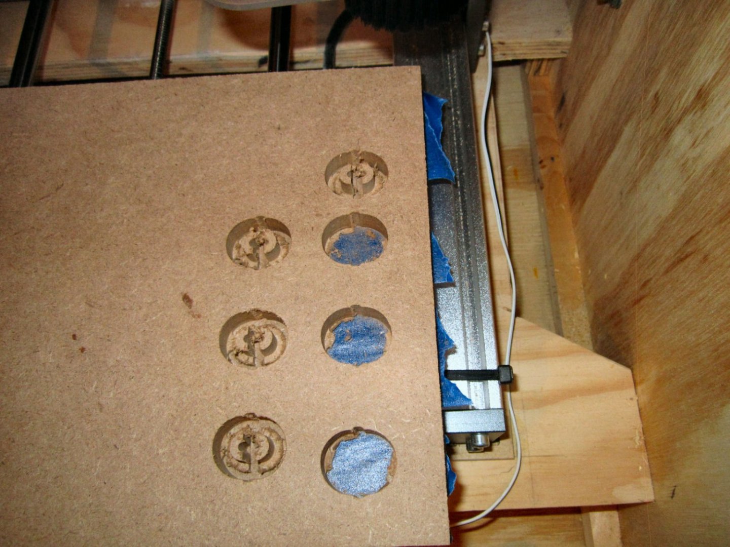
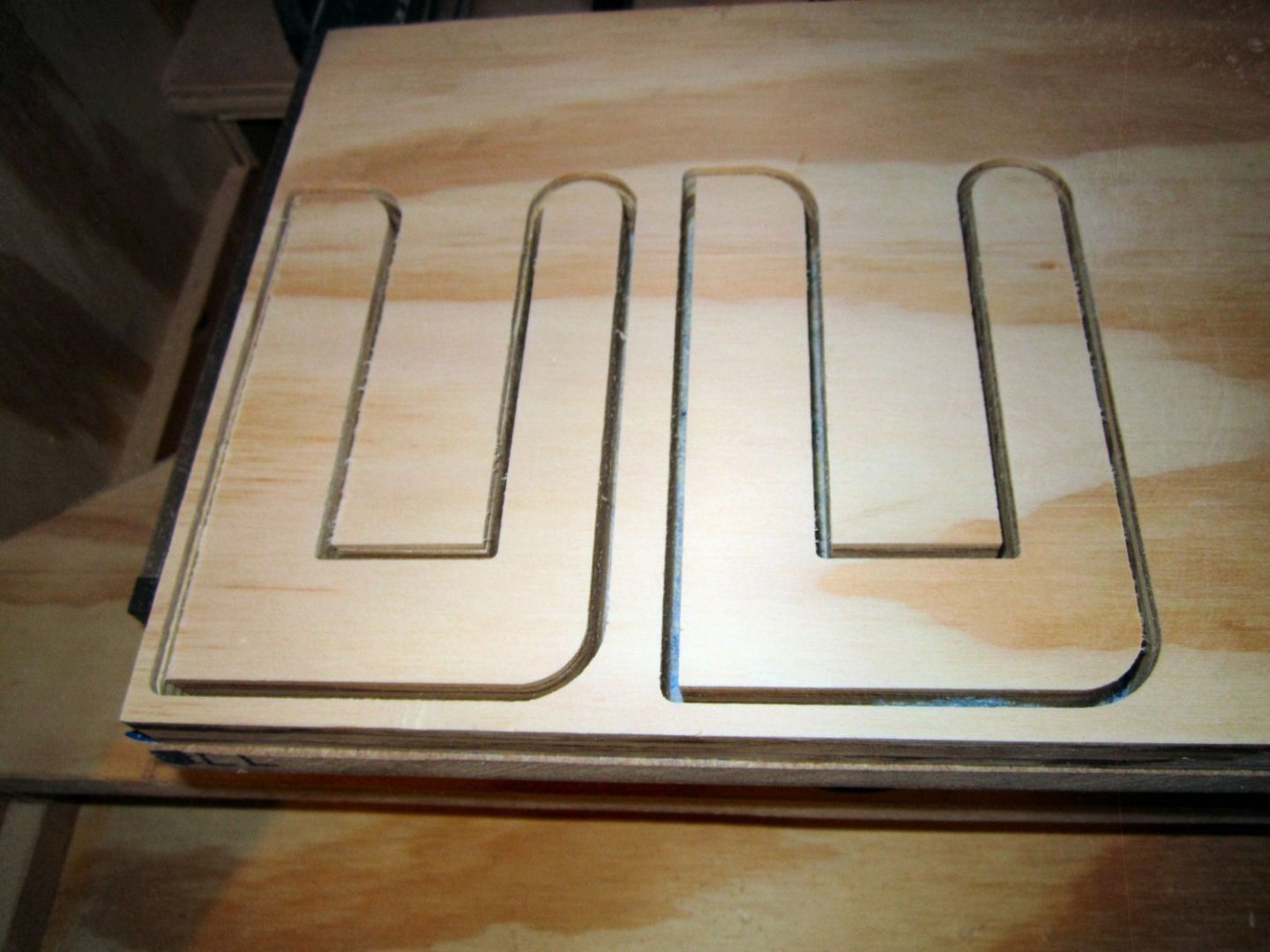
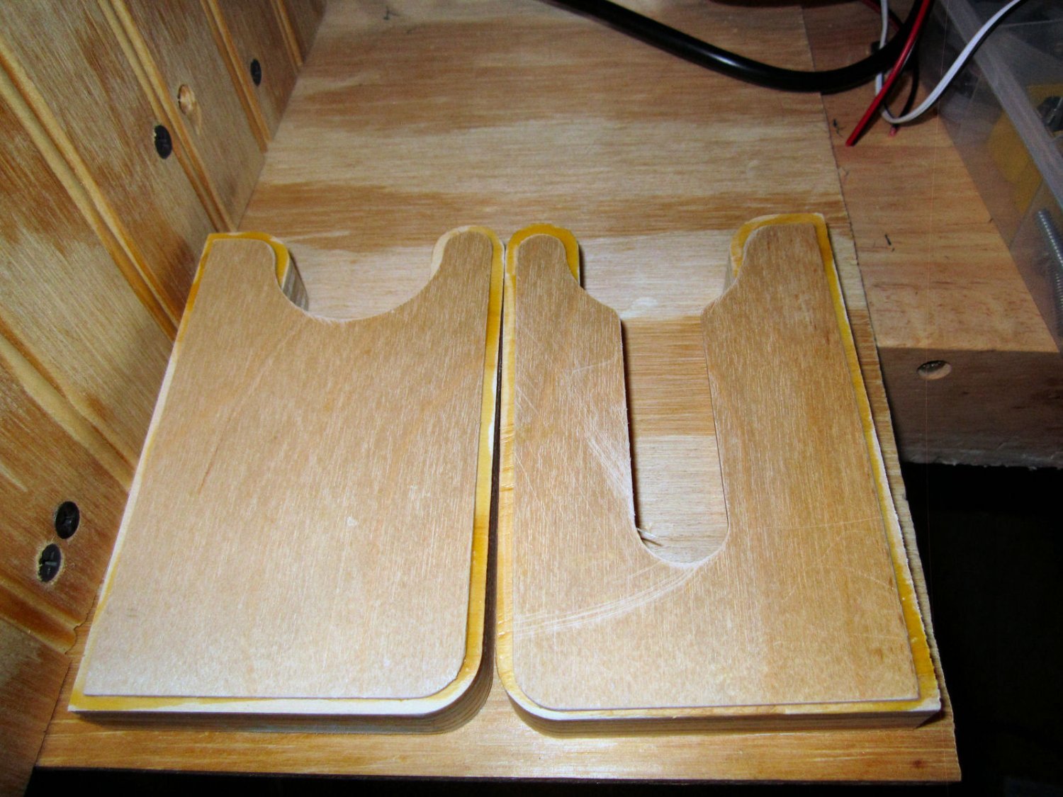
I changed the cutting order so the slot for the inner hole, and the one that separates the two halves was cut first, instead of last. I thought maybe the separating cuts were stressing the parts. The same failure occurred.
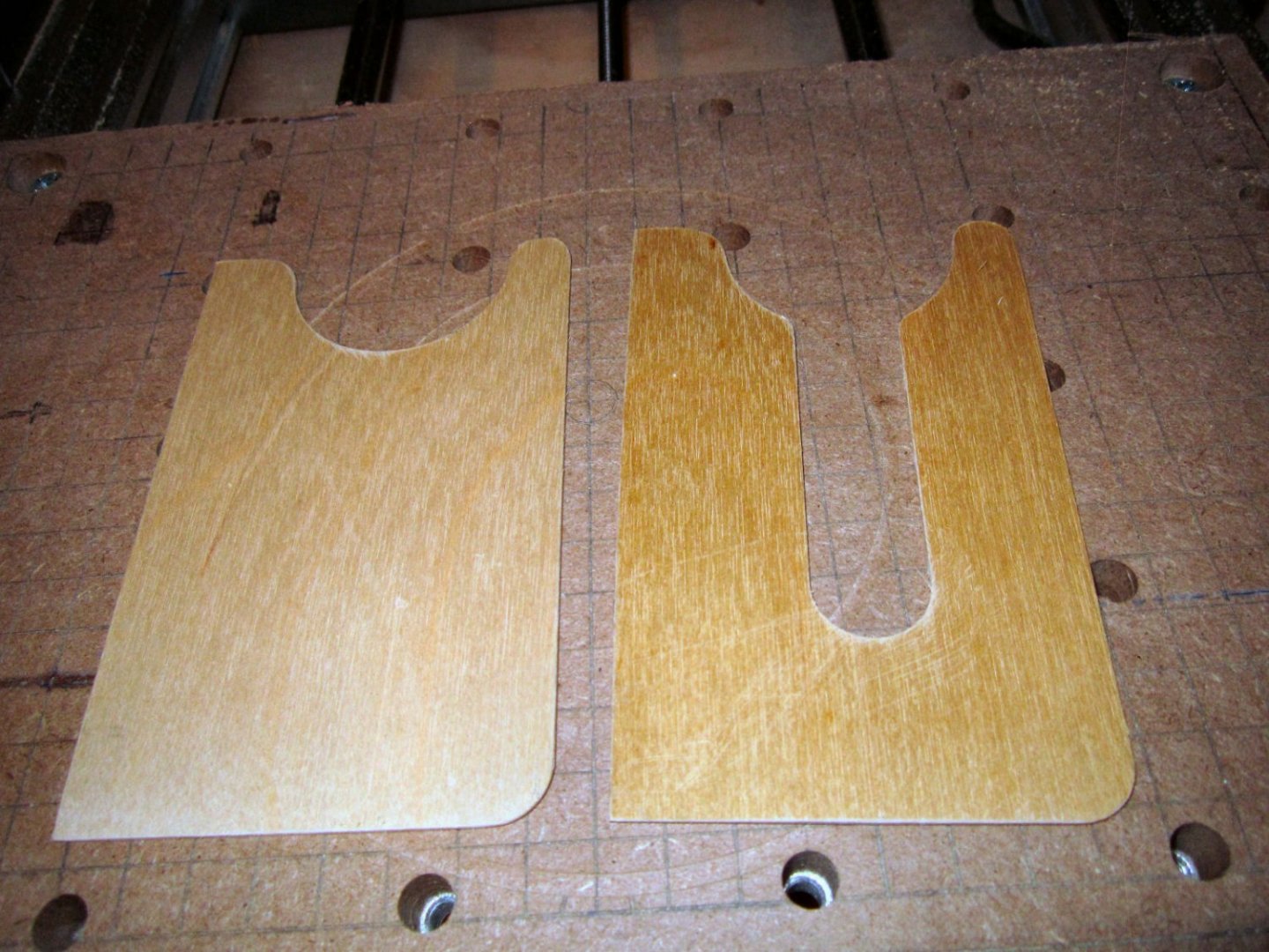
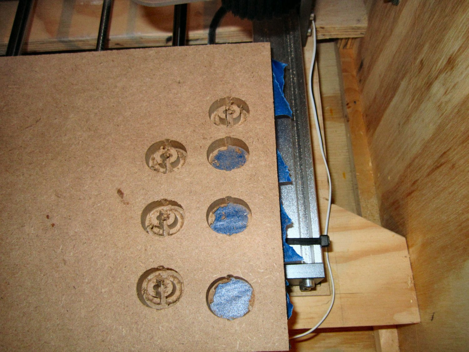
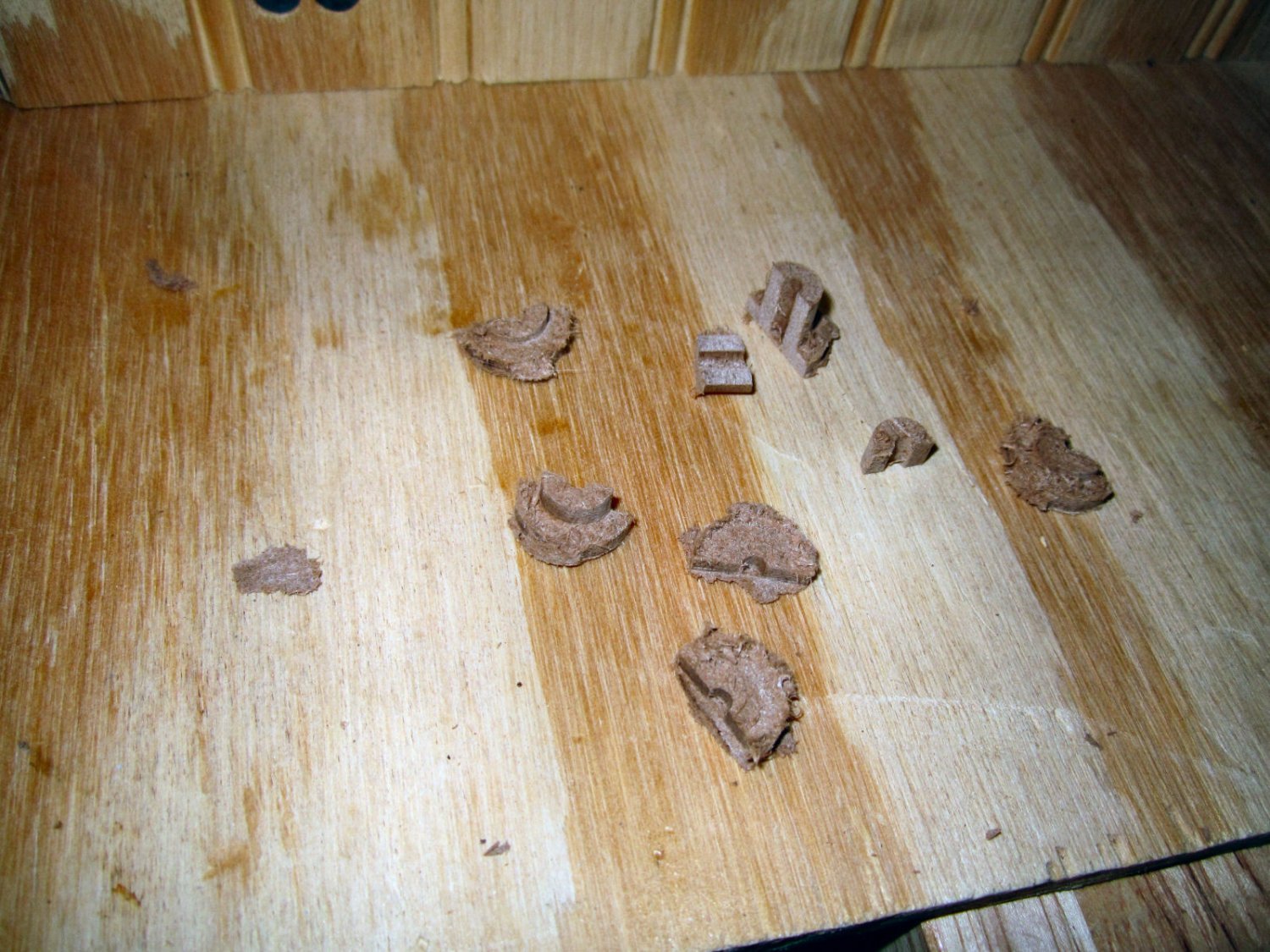
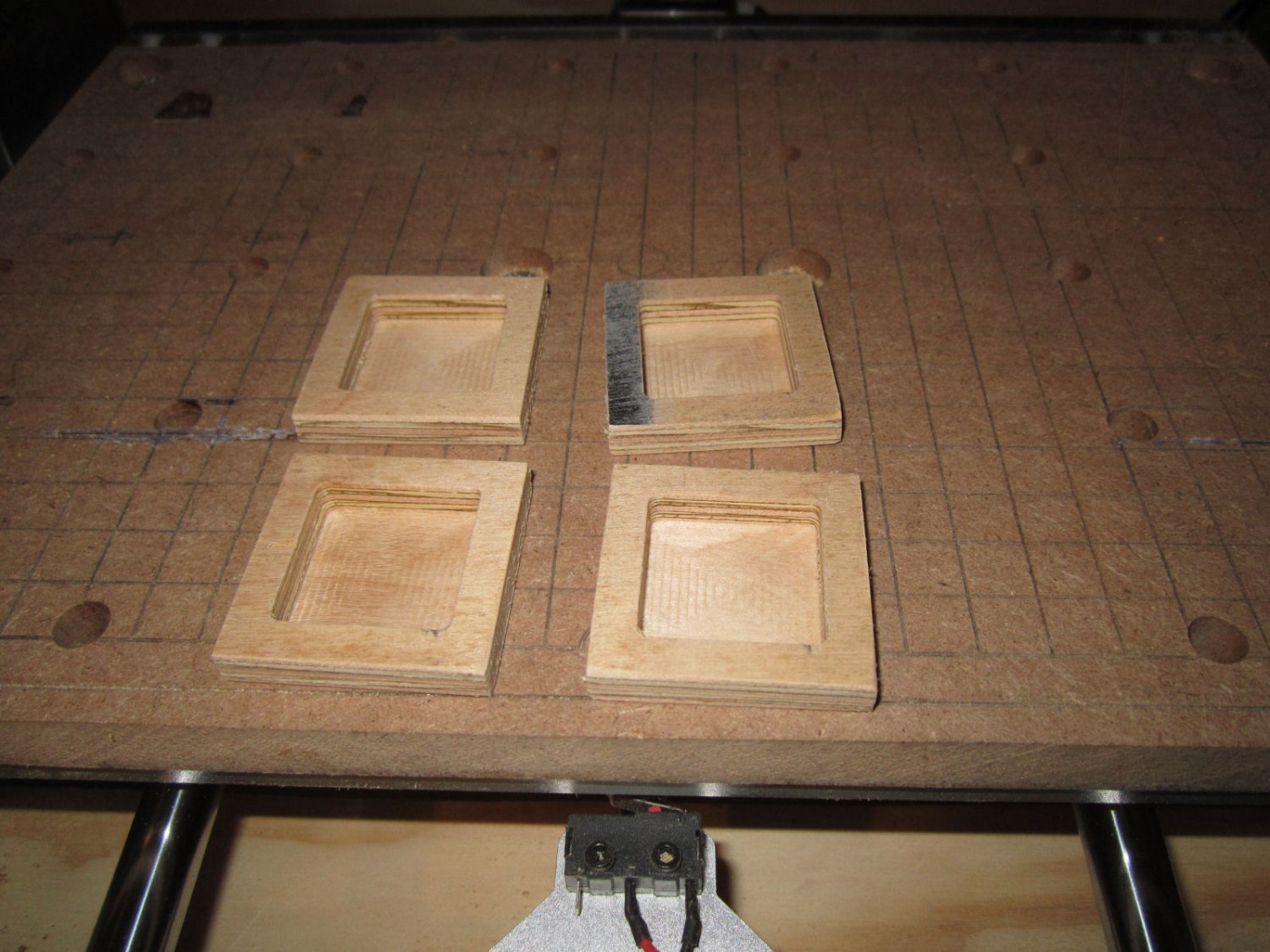
Next I thought slowing the cutting travel speed down might work. I changed the speed from 13mm/sec to the Carveco default of 7mm/sec. That worked much better! Out of 4 attempts (8 halve pieces), I got 5 good halves. The picture below seems to show all the pieces coming out, but 3 broke while I was removing them.
To strengthen the good pieces, I coated them with thin CA, while they were held in place on a piece of blue tape.
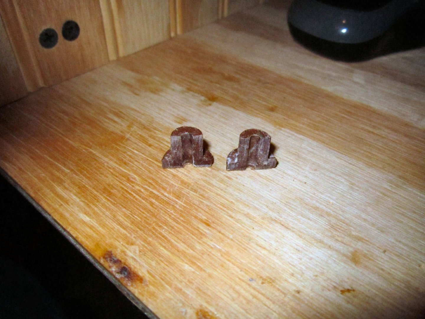
The coating increased the dimensions slightly, but they still fit in the hole, and tightly now. The white “Powder” in the pictures is the CA after I sprayed it with the accelerator. CA tends to do this, but I did not want to wait for the CA puddles to, maybe, set. A little sanding removed the roughness.
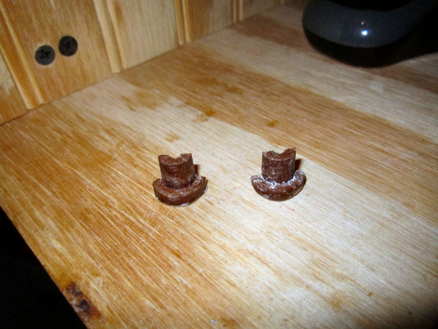
Because the CA also reduced the diameter of the center hole, I pushed the plug into a 3/8” hole in some scrap, and redrilled the hole to 1/8”.

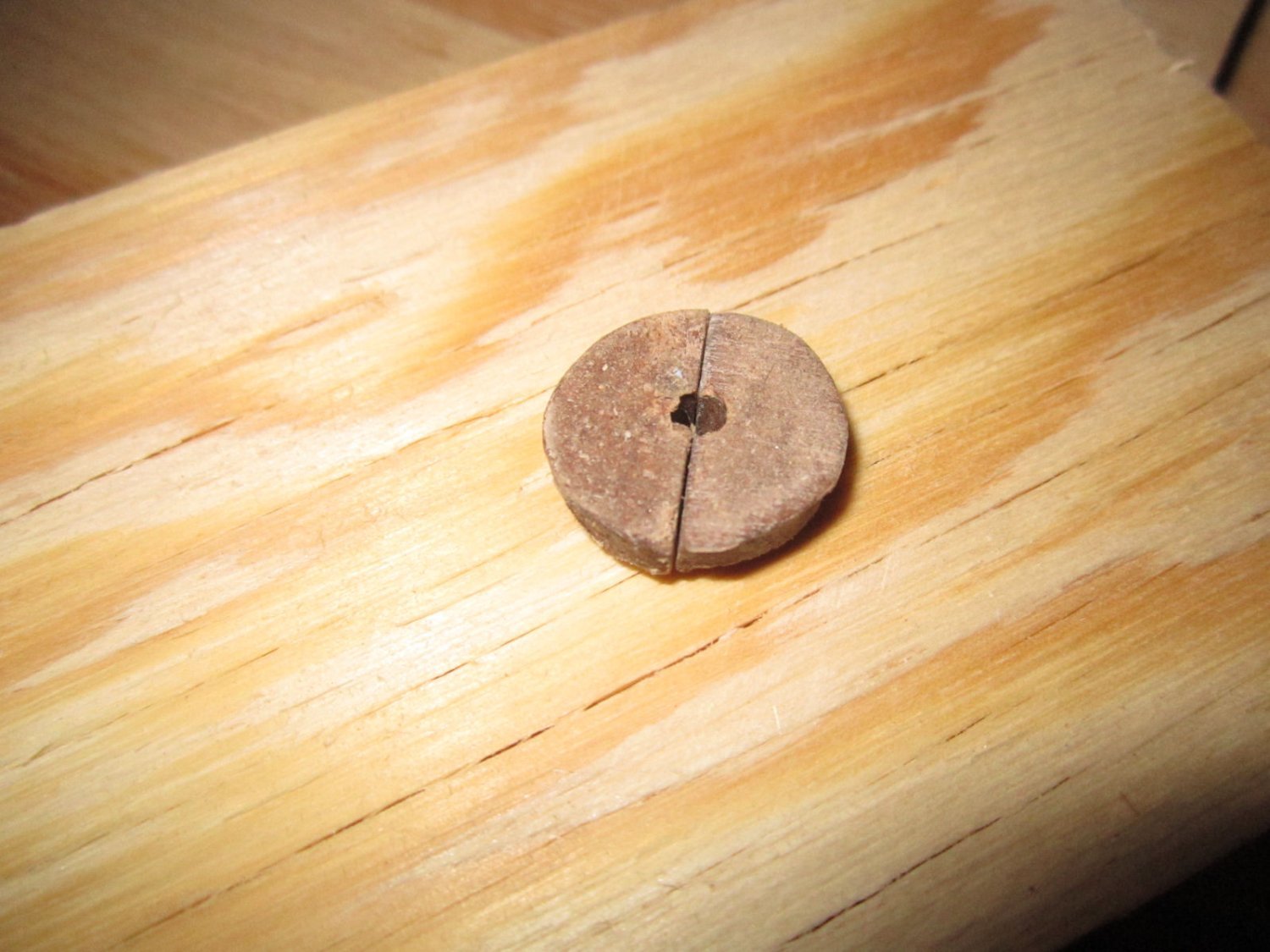
I repeated this for the second good plug, and stored it away for future need.
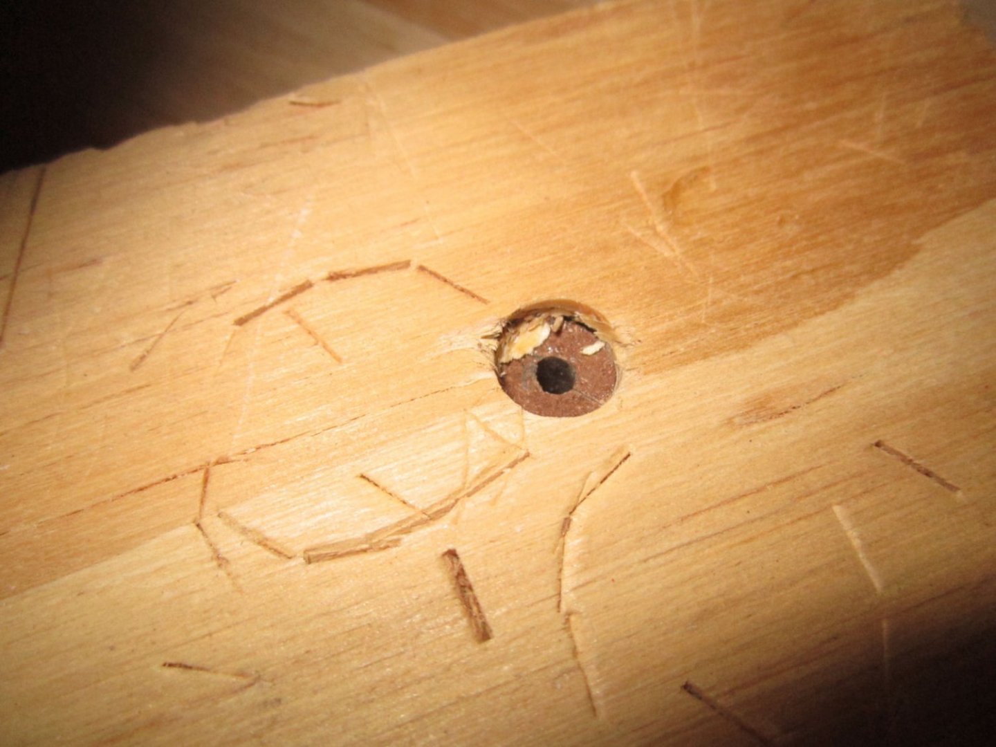
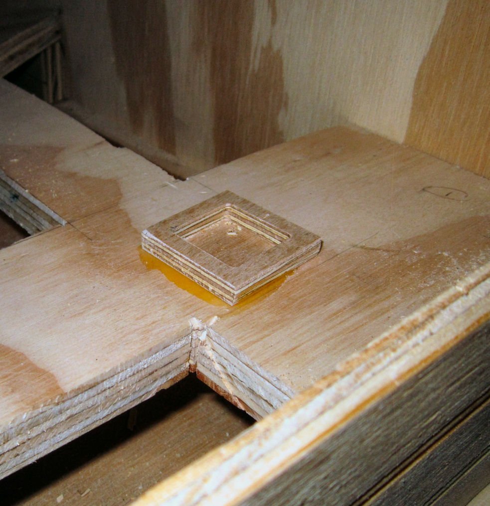
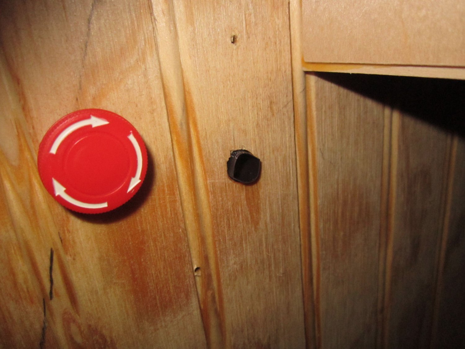
Here is a picture of the plug installed.
After I had finished the plugs, SpindleJockey, who does CNC all the time, suggested the following bridge tab configuration.

I’ll file that away for future reference!
-
-
Part 023 – Miscellaneous
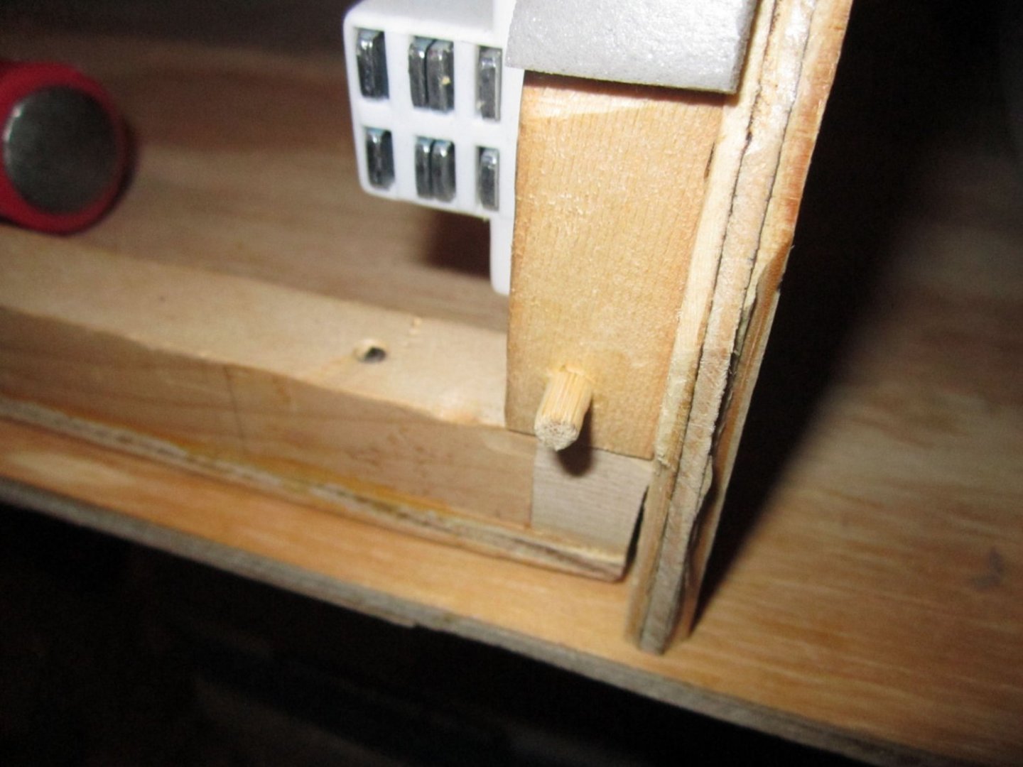
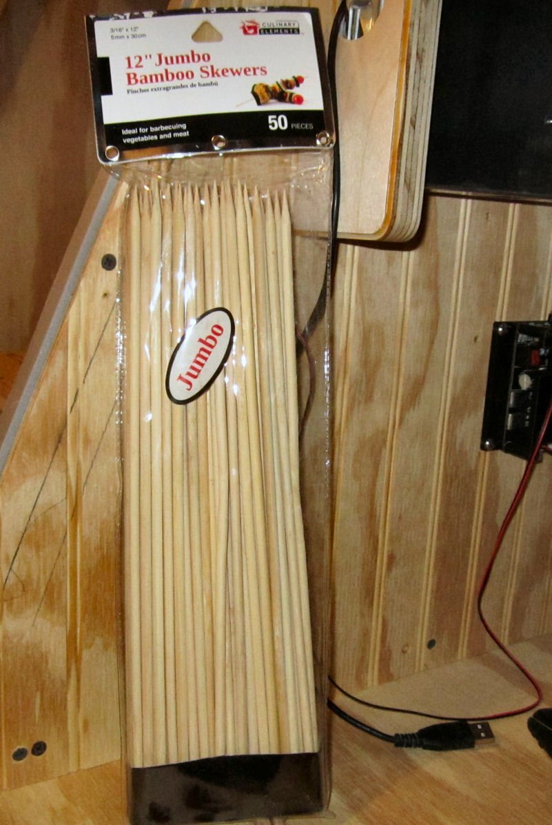
I decided not to hinge the front piece. The magnets were holding it well, with just the temporary nails for guides. I bought some bamboo skewers, that ended up being about 3/16” in diameter.

I clamped one side of the front and removed that nail, then drilled 3/16” using the nail hole as a guide. Next I drilled the front 13/64” for a nice sliding fit on the dowel, as well as just a very short depth into the enclosure, to guide the insertion of the dowel. I glued the end of the dowel and drove it in with a hammer after cutting off the point. After cleaning up the excess glue and allowing it to dry about a half hour I reinstalled the front, and repeated the process for the other side. I cut off the extra dowel and sanded it flush, then slightly rounded the exposed end.

I designed a plug for the E-Stop wire, but the router failed in cutting one in either 13mm MDF, or regular ½” plywood. In six attempts (3 in each) the parts broke before the cuts were completed, and I was unable to get two good halves. The body of the plug is 3/8” diameter , once the two halves are fitted, with a 1/8” center hole.


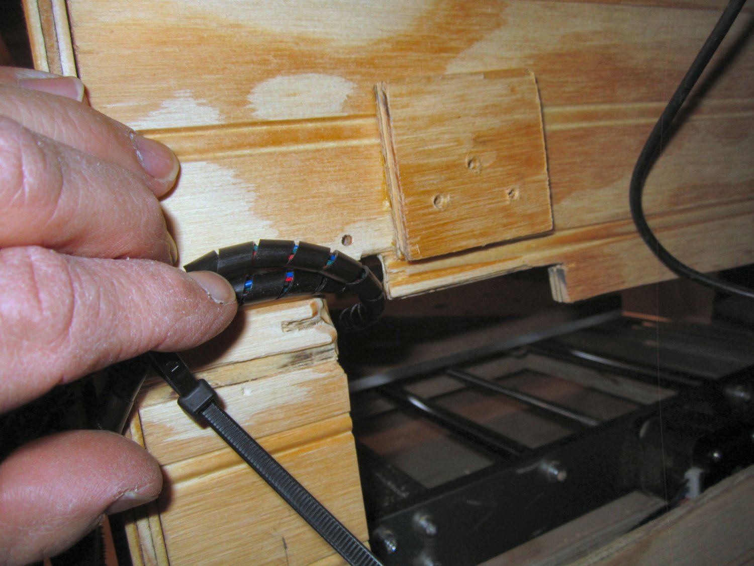
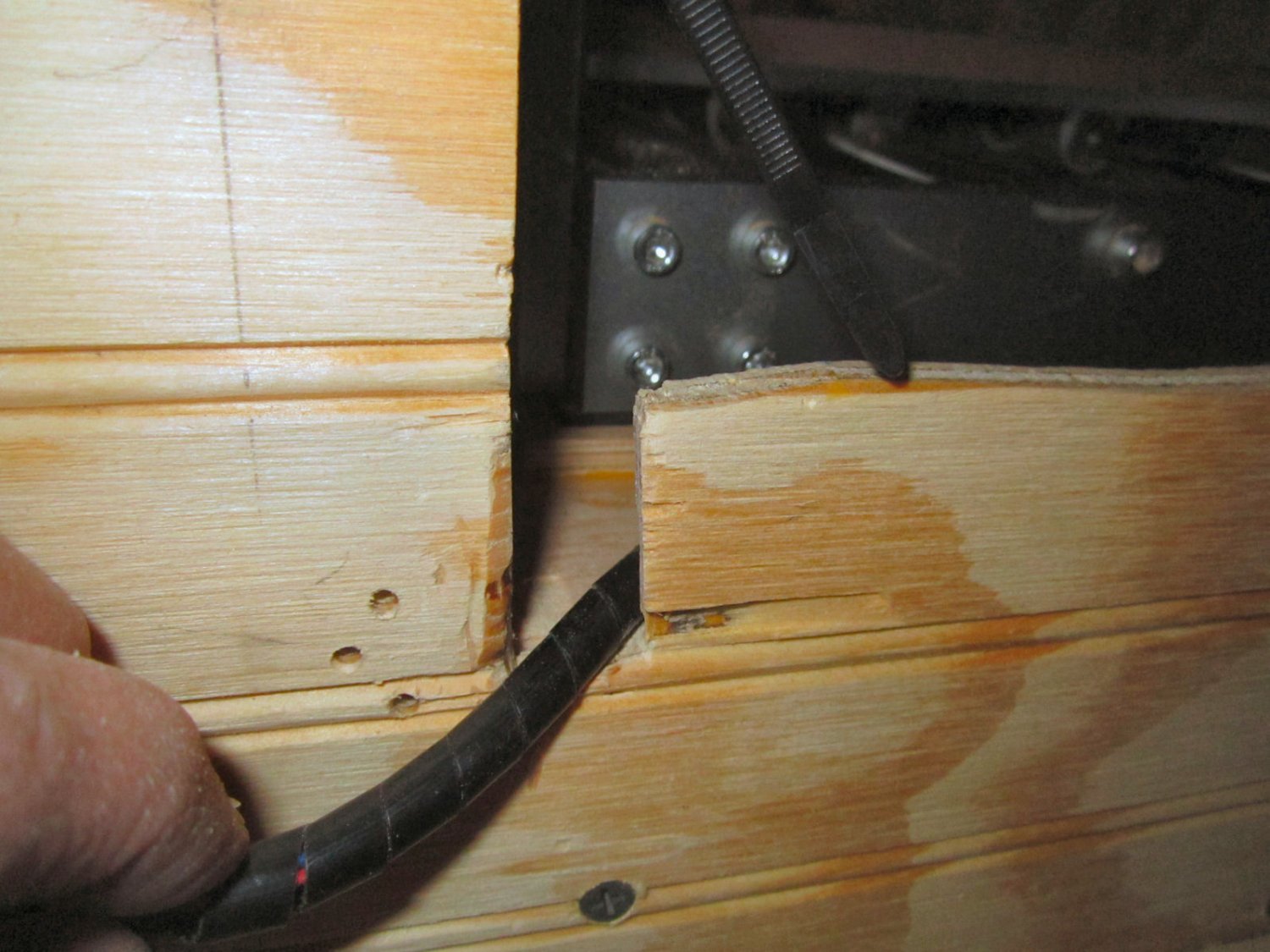
So, for now, I put a piece of 3/8” heat shrink tubing in the hole, to keep the wire from chaffing.

I will try again, reducing the cutting traverse speed, or I may try it in a thick piece of plastic cutting board I have. I’ve used pieces of this cutting board to make new sheaves for the rotted ones in the pulleys on a 23’ sailboat, and the rollers for the sliding doors in my shop, so it is quite a durable plastic.
I also cut a second center for the vacuum jig, with a 1 ¾” hole in the center to allow me to place the vacuum hose hole to clear the corner battens.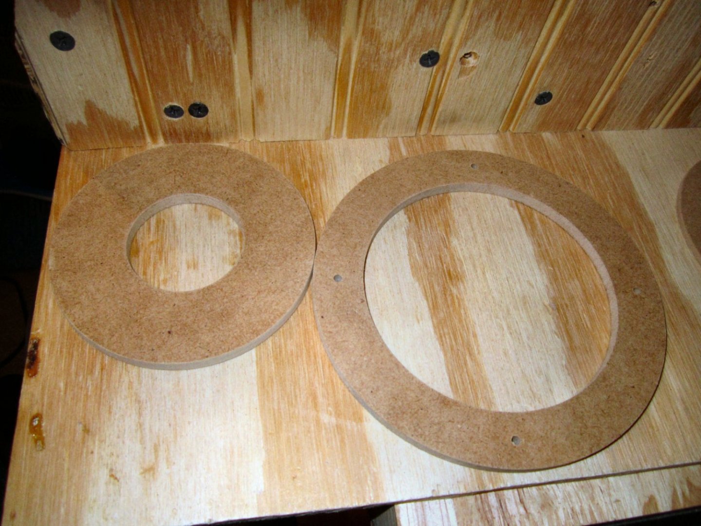
I still have not decided on the final location for the hole, or the exact way I’m going to mount the hose to the enclosure. I’ll detail that later. My present shop vac has a 1 ¼” OD hose, so I need an adapter to mate it with the 1 ½” ID hose I want to use inside the enclosure. I’m going to use the 1 ½” hose, in case I get a larger vacuum, in the future.
-
-
-
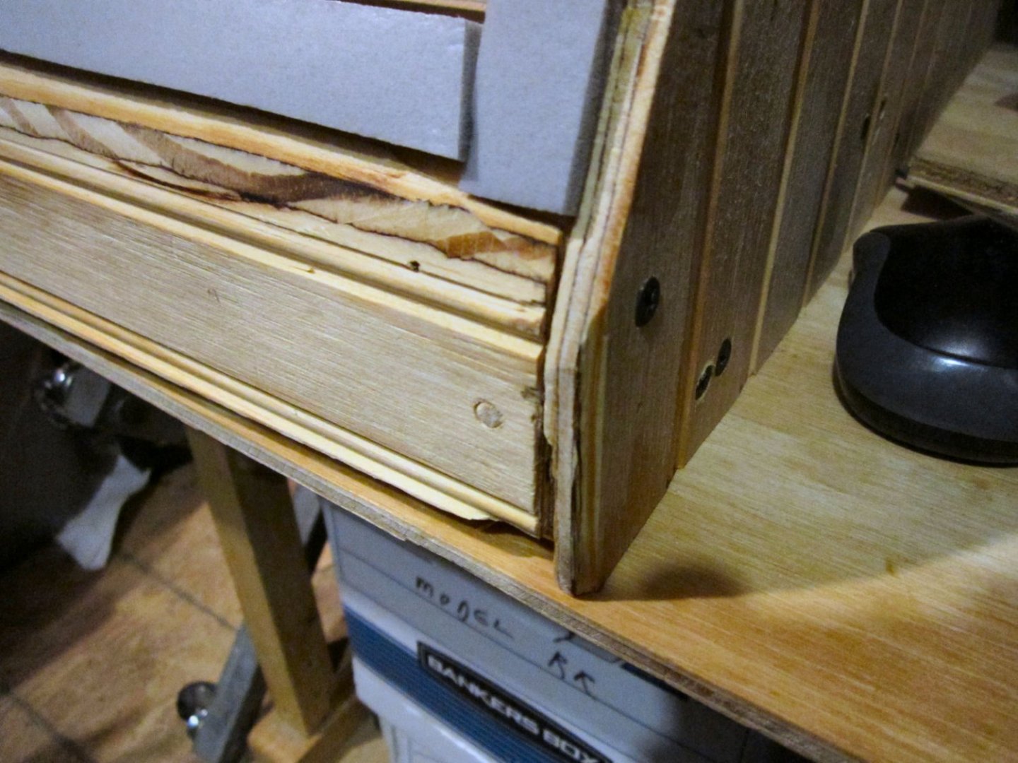
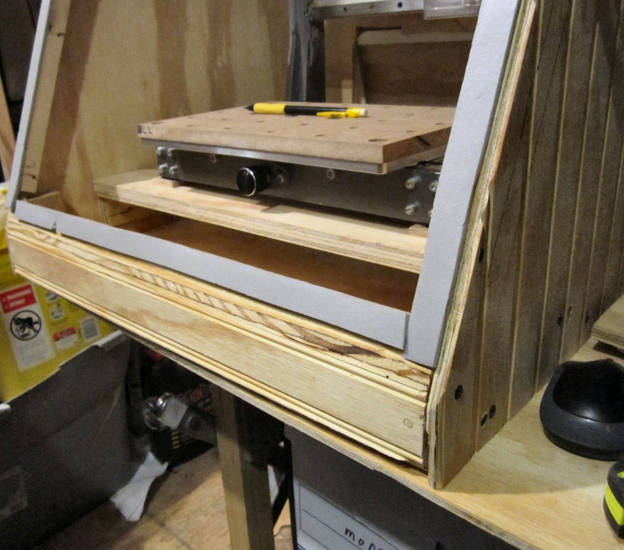
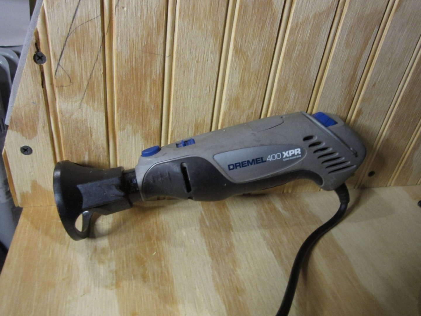
Part 022 – E-Stop Button Installation, Outside Enclosure, with Guide for Routing a Recess
My next step was mounting the E-Stop switch on the outside of the enclosure. No problem, just drill a 5/8” hole and pop it in. Nope! The threads on the switch for the mounting nut are only about 3/8” long, so putting the switch into the 3/8” thick enclosure plywood, left no threads the nut could grab onto. So I needed to cut a recess a little over ¾” in diameter into the side of the hole. I also need to cut a nice circle in the other side for the 1 ½” vacuum hose, for the dust shoe.As can be seen from previous posts, my skills at cutting a smooth, specific size hole, in the vertical side of a box with a saber saw, leaves something to be desired! I, however, do have a router attachment for my Dremel. I measured the diameter of the attachment base, and allowing for a 1/8” bit, I designed a ring for the E-Stop recess, and a larger one for the vacuum hose. The rings are to be mounted on the enclosure, and the base of the Dremel run around the inside, cutting the desired size recess/hole. As I’d already drilled the button hole, I also designed a removable center piece to fit inside the ring, with a 5/8” nub in the center.
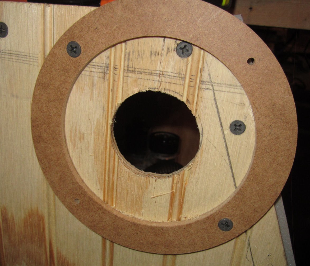
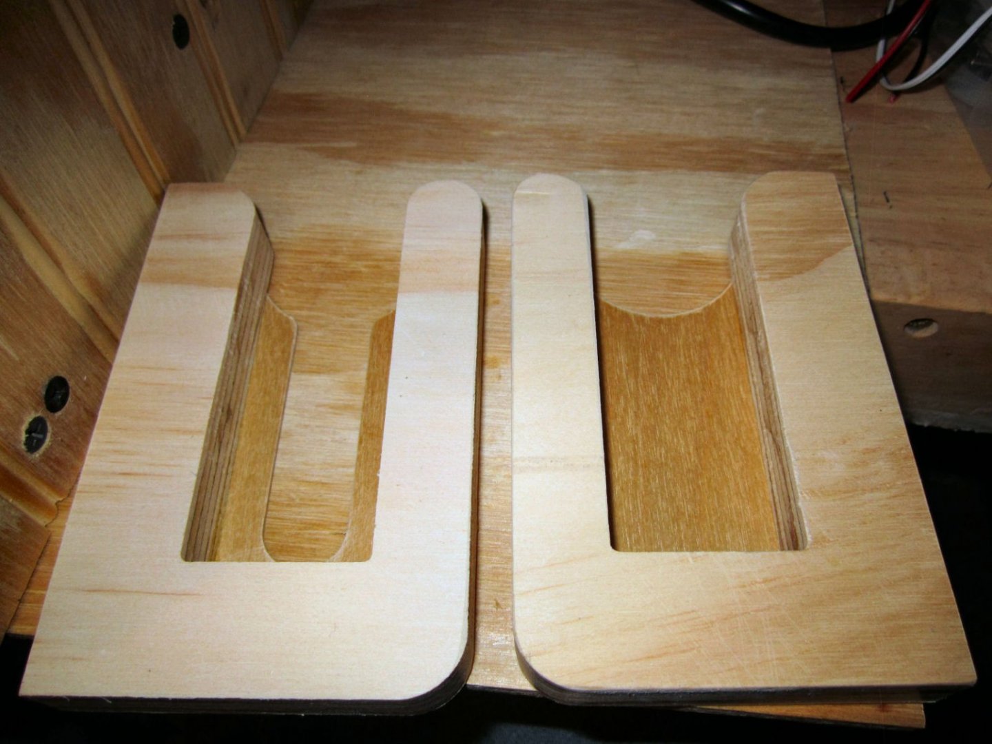
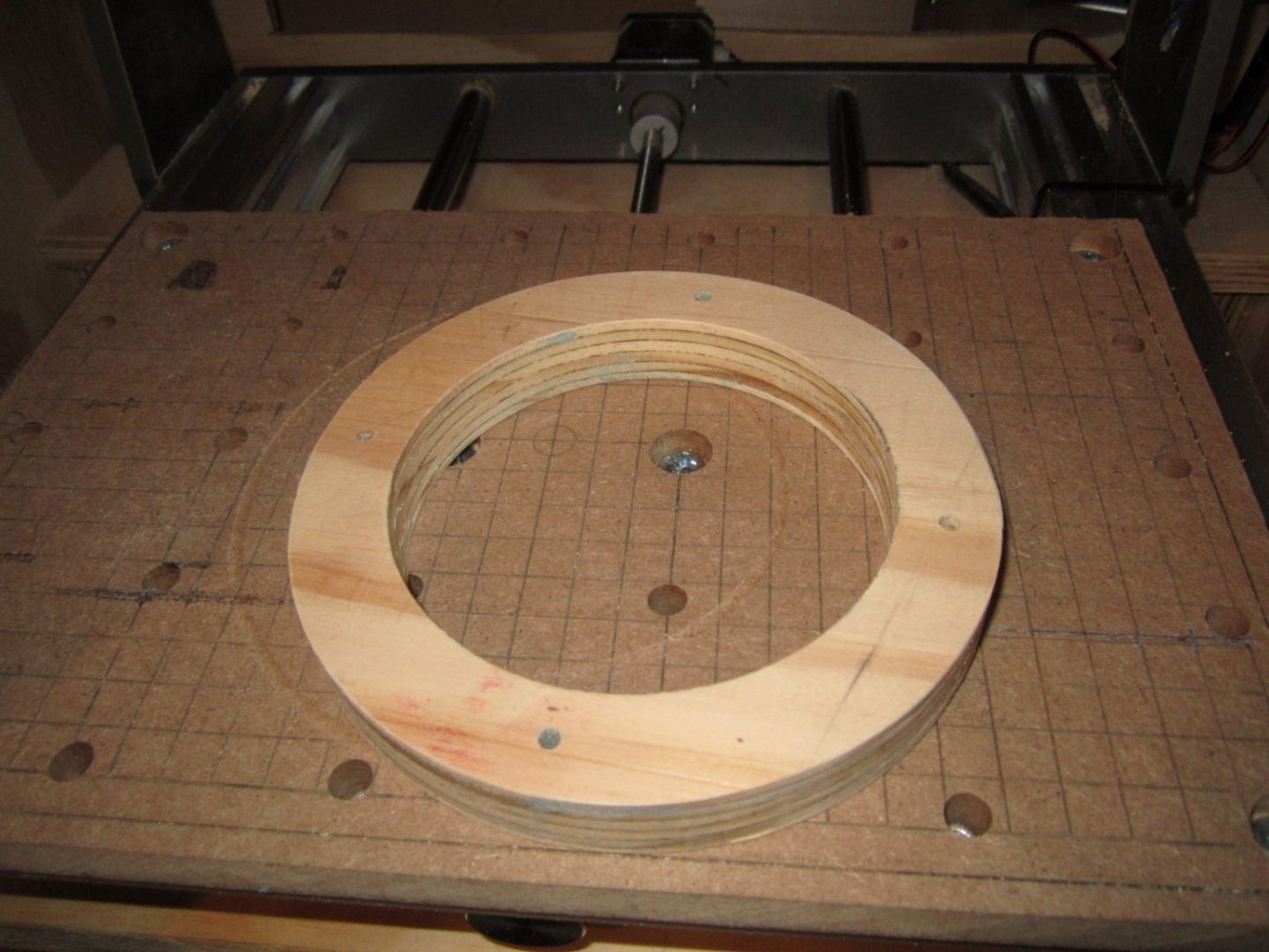
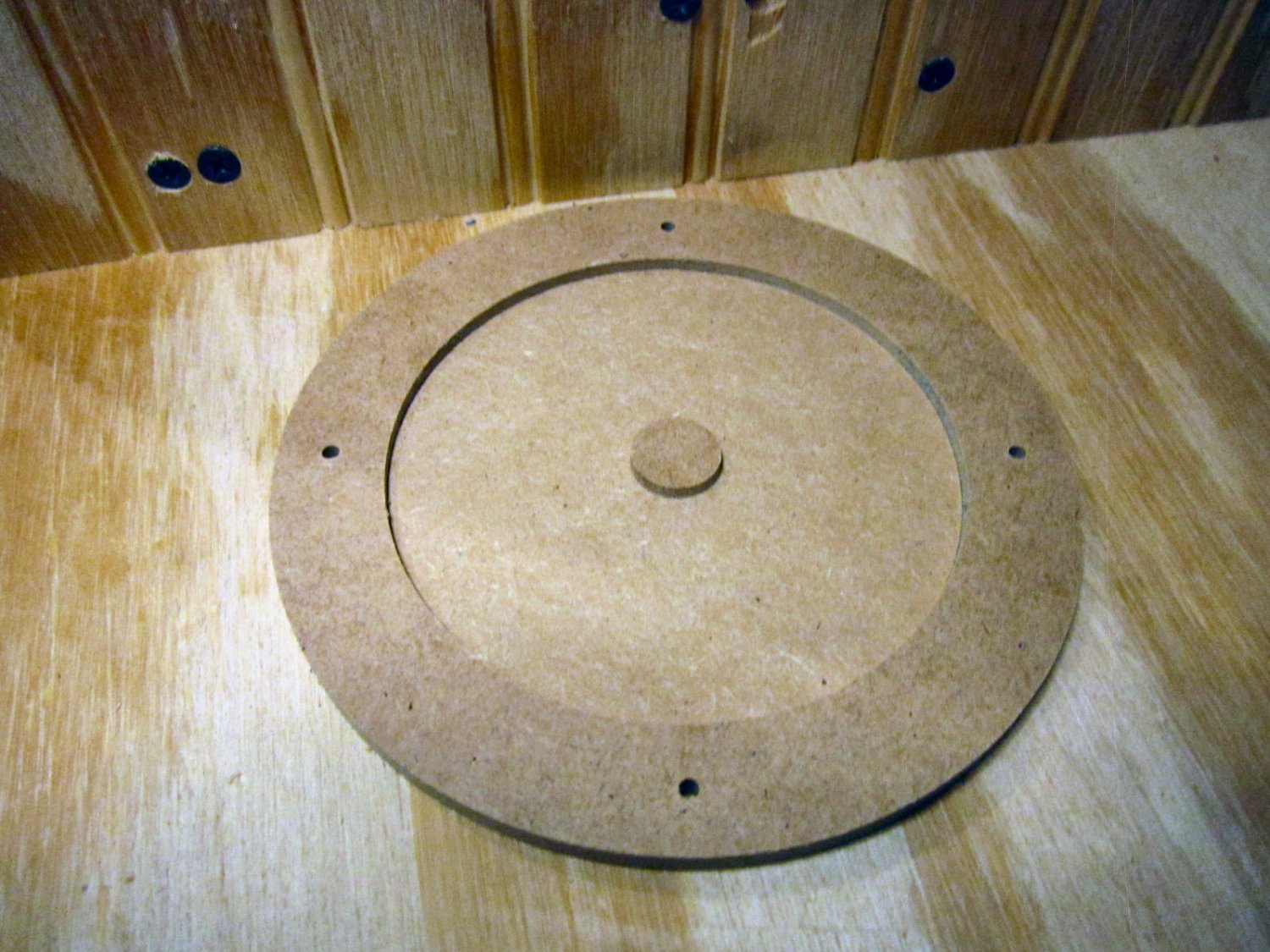
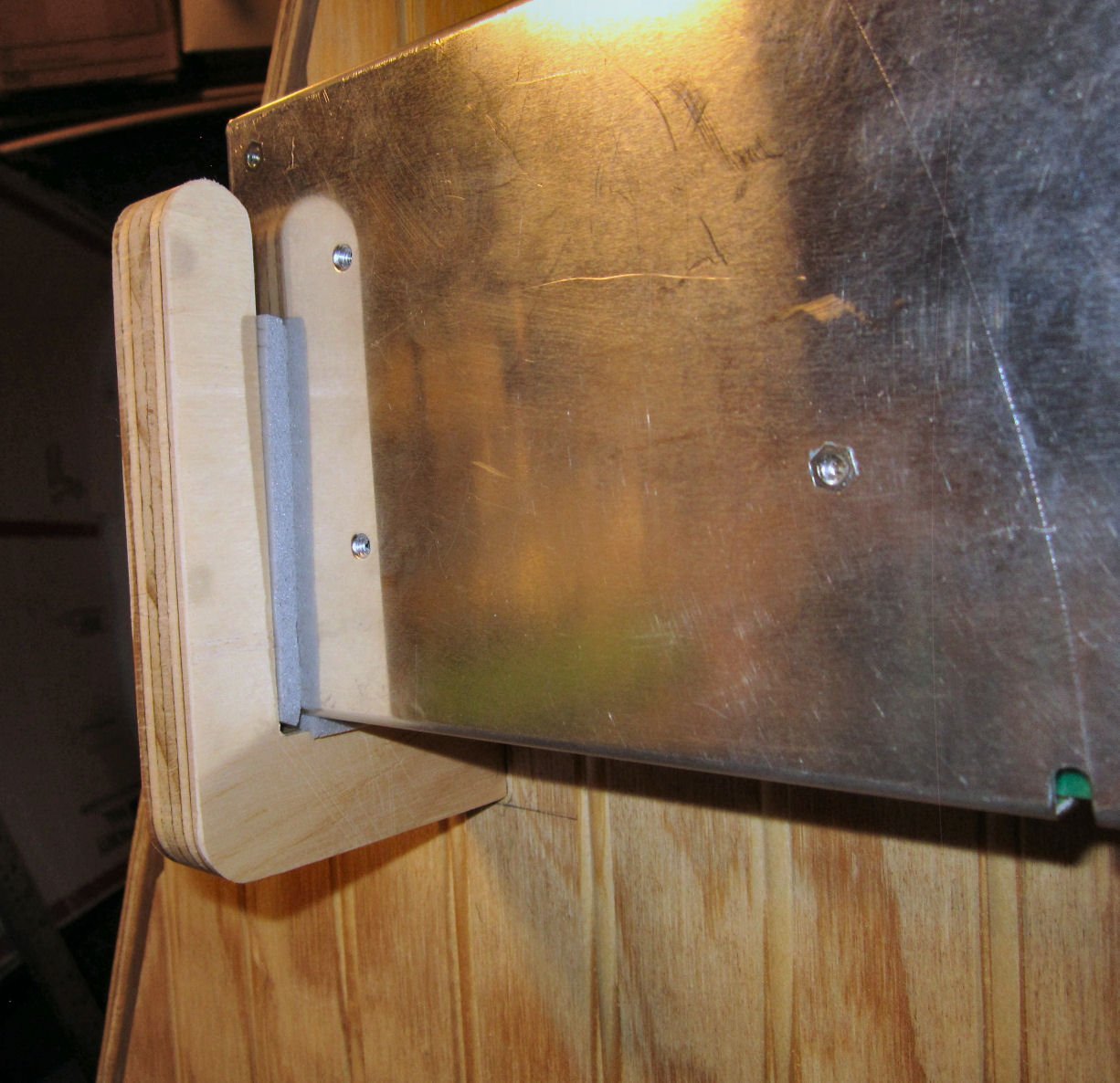
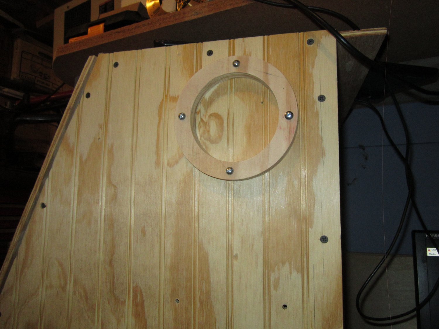
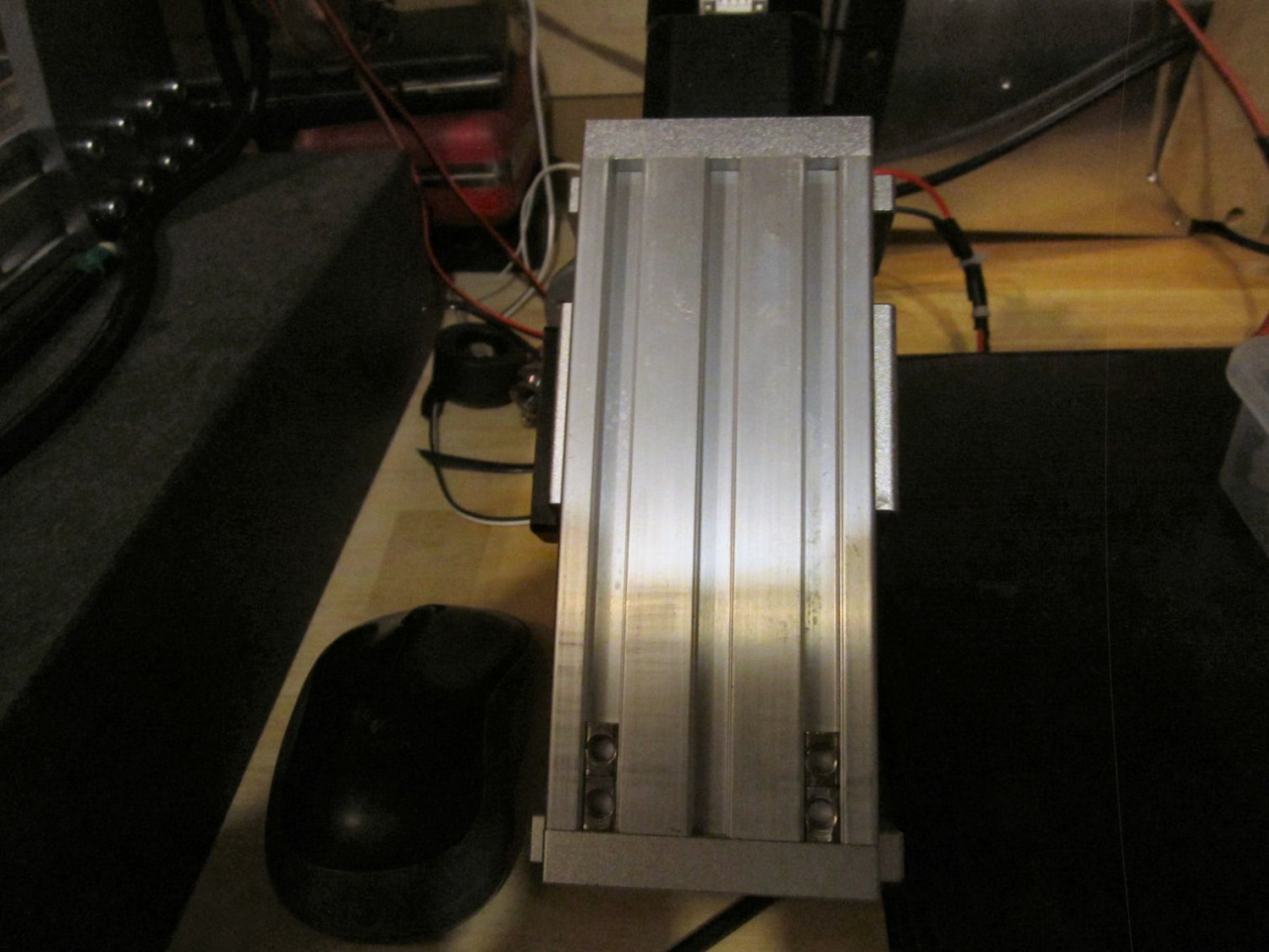
Here is the larger ring and center for the vacuum hose. I did have to sand the outside of both centers a little to get them to fit into the rings, the problem with backlash in the feedscrews. The E-Stop ring is similar, just smaller.
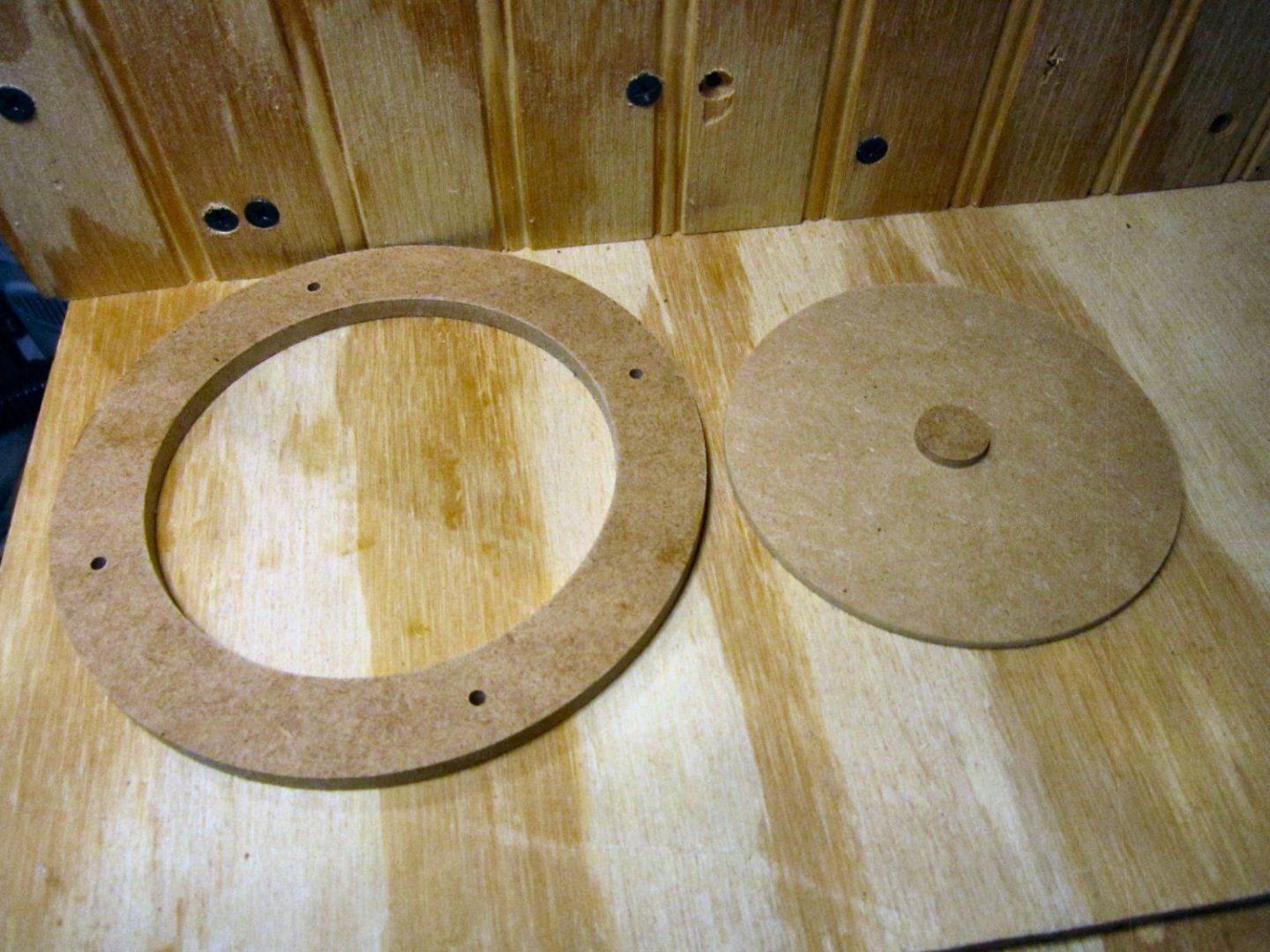
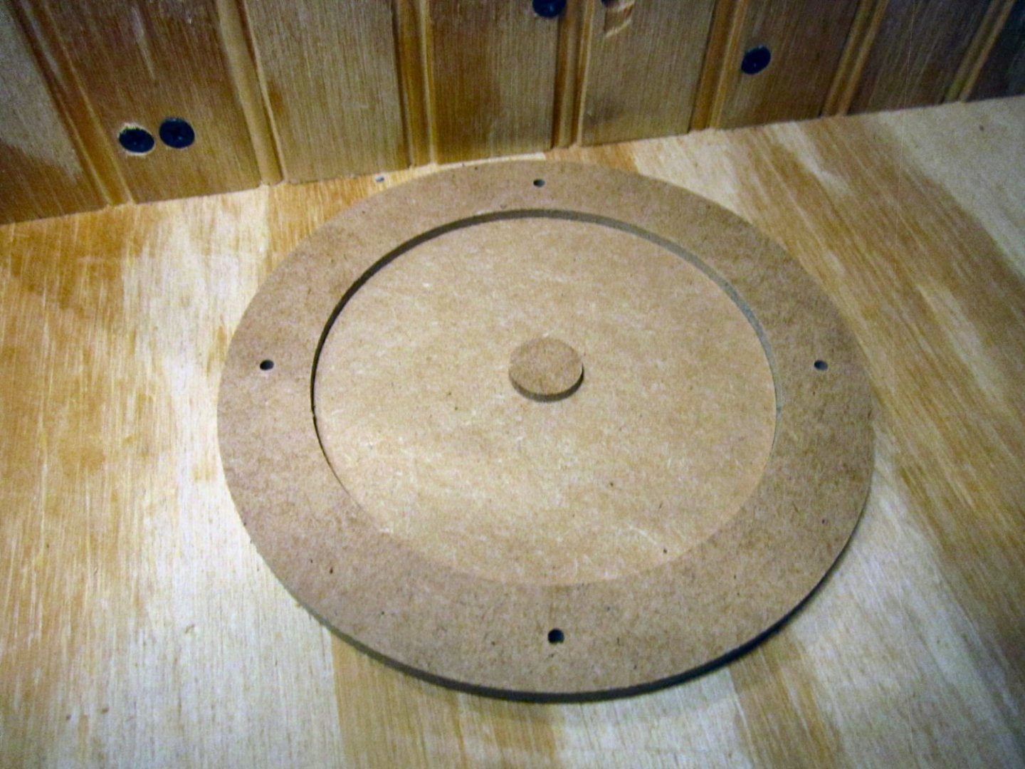
For the vacuum hose I may not need the center piece, but I’ll have it if needed. I will have to drill at least a starter hole for the bit, anyway.
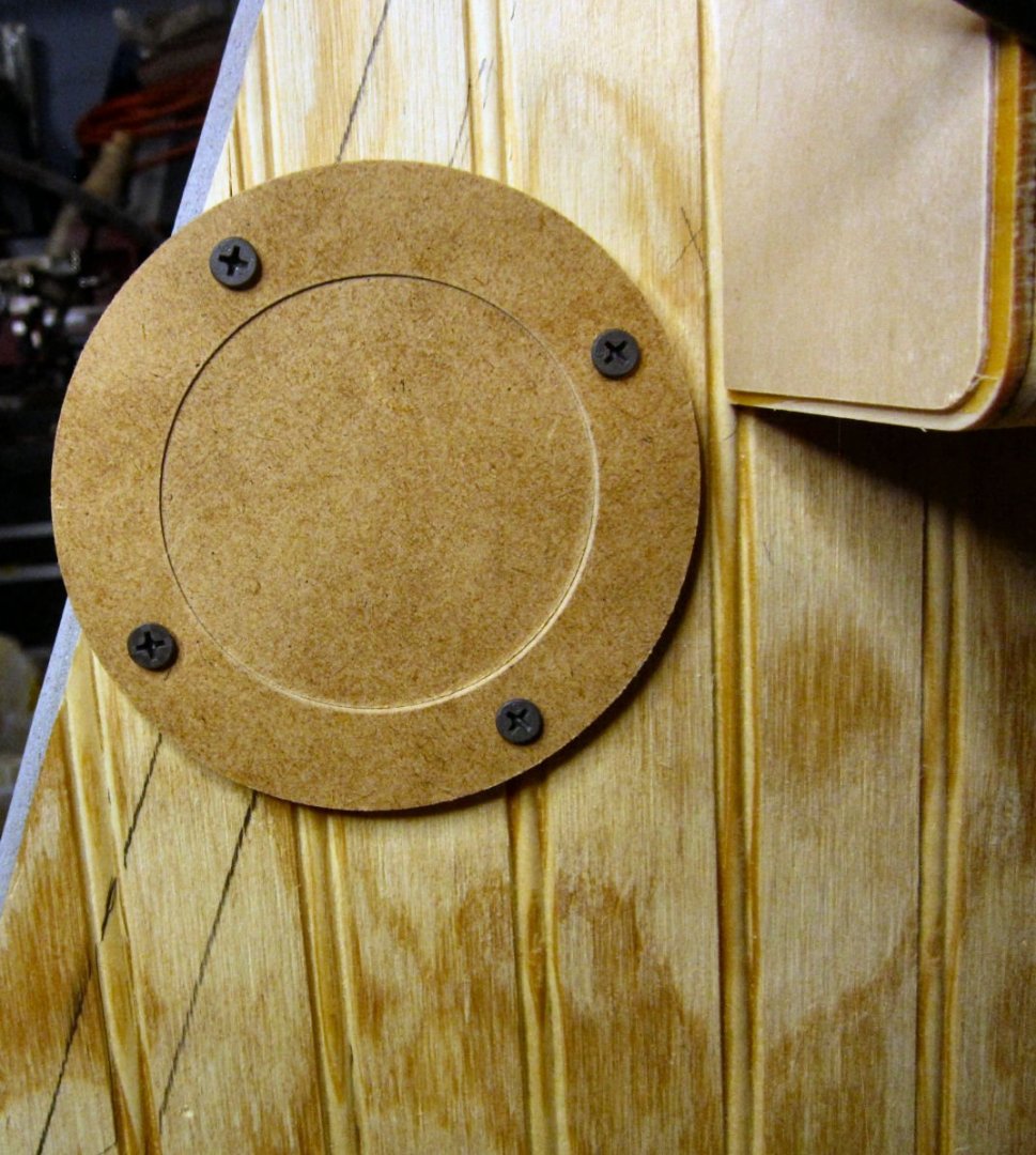
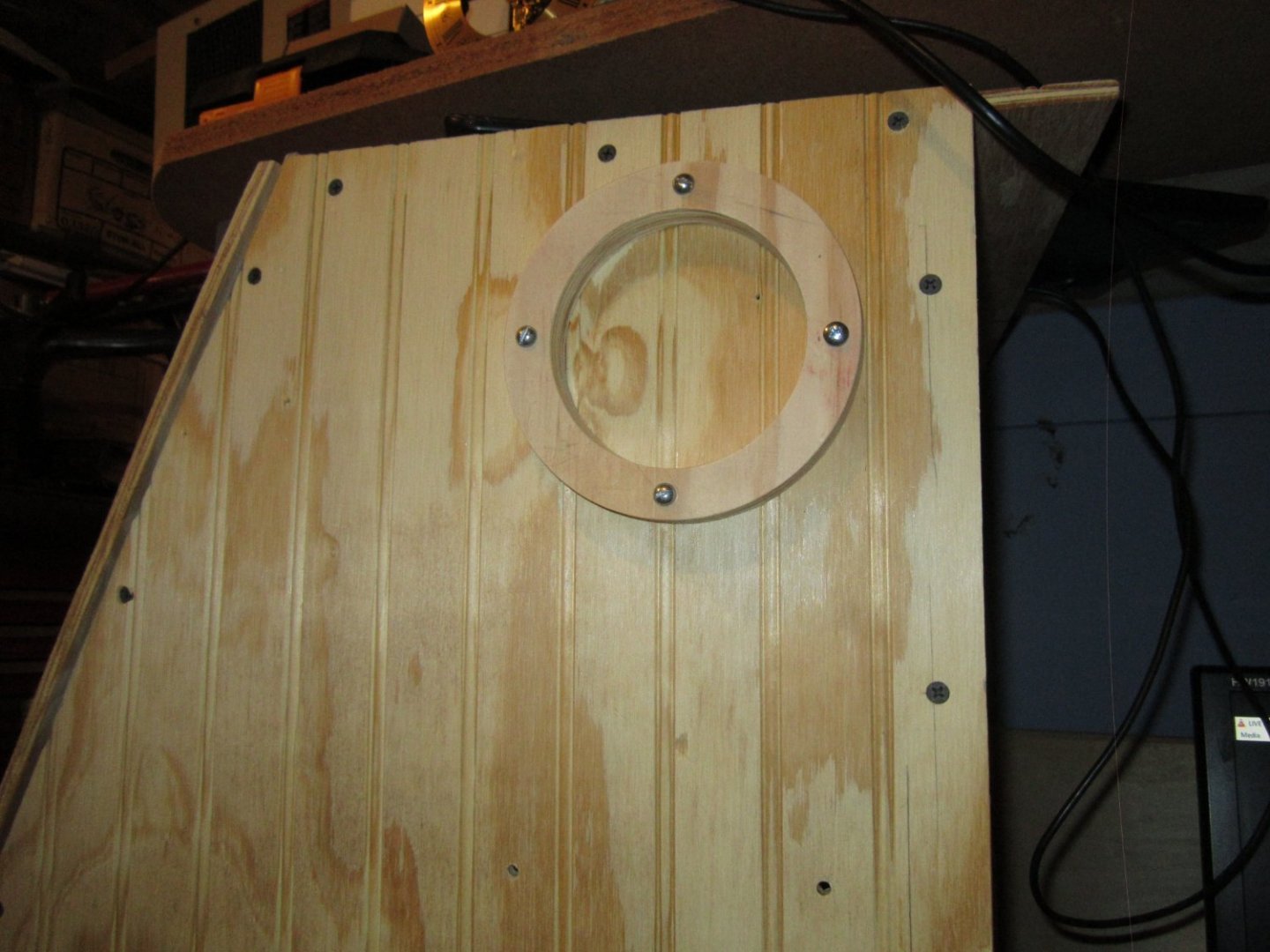
This picture shows the center stuck in the already drilled hole and the ring screwed in place using the center piece to locate it.
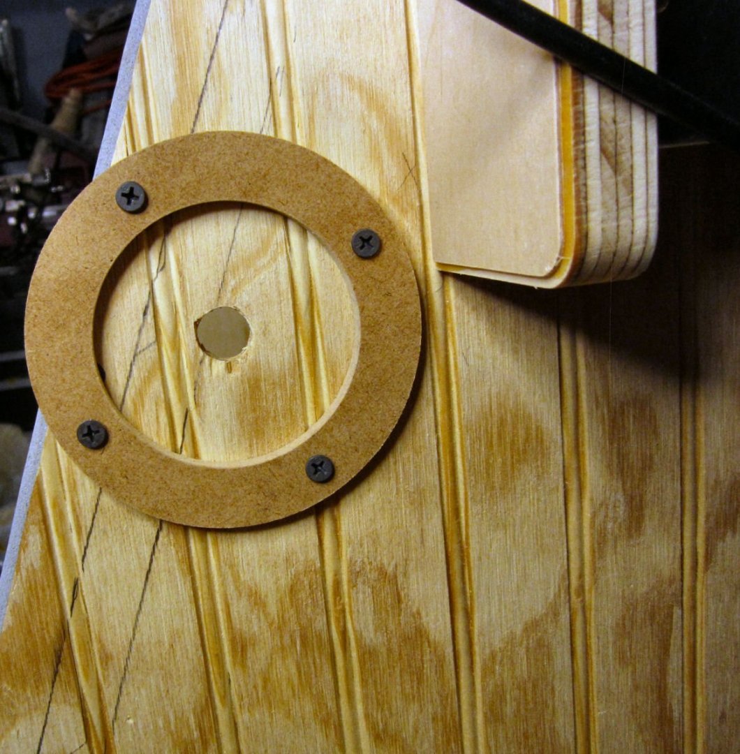
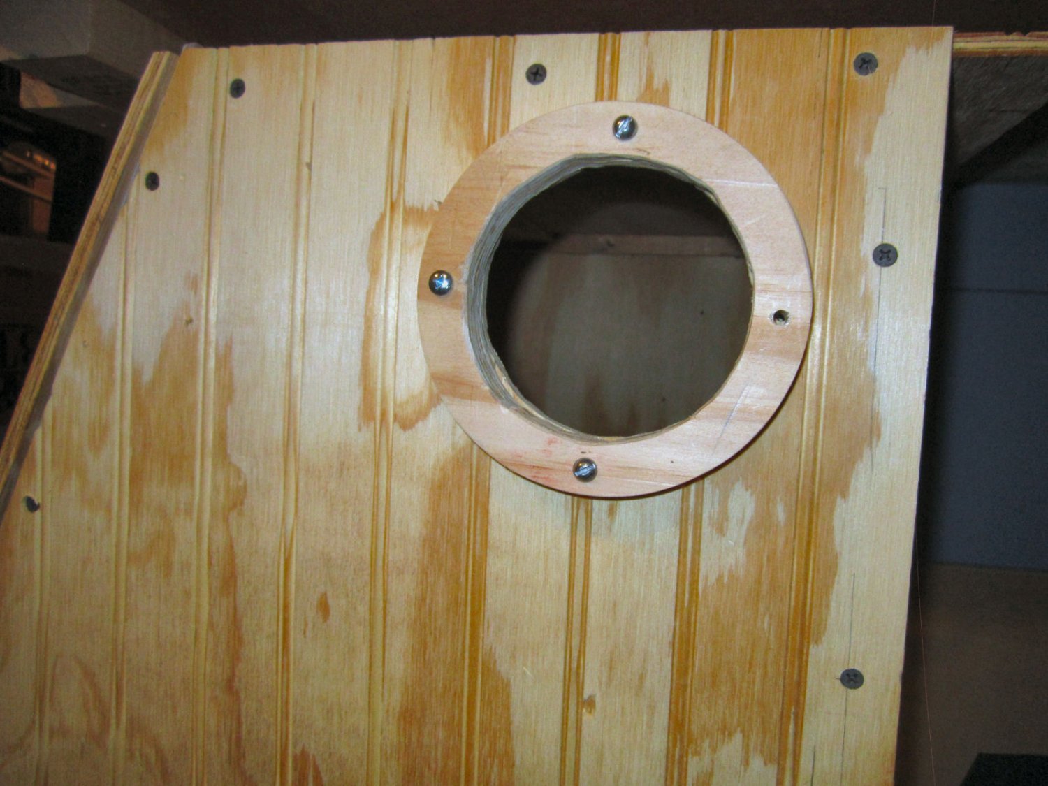
And, this one with the center removed.
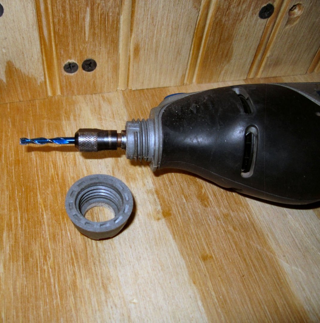
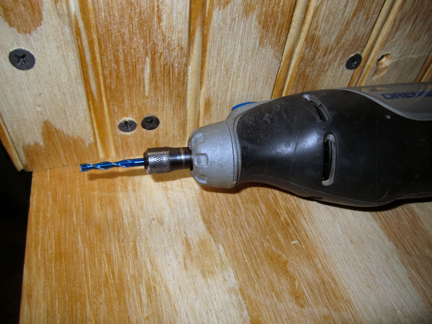
These pictures show the Dremel, the Dremel with the nose screwed off, and the attachment installed. I used one of the SainSmart 1/8” bits for the operation.

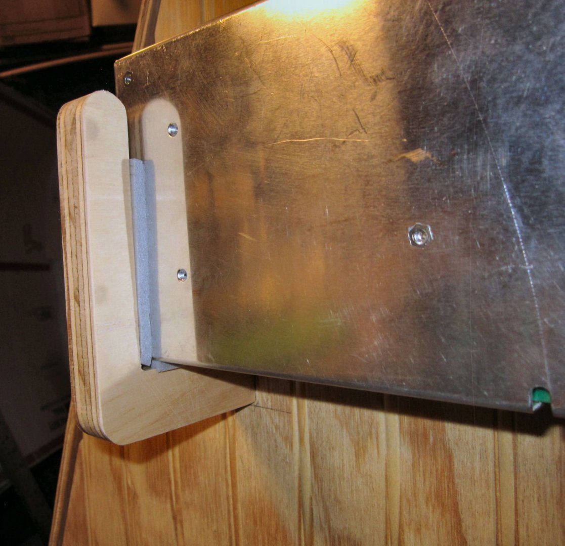
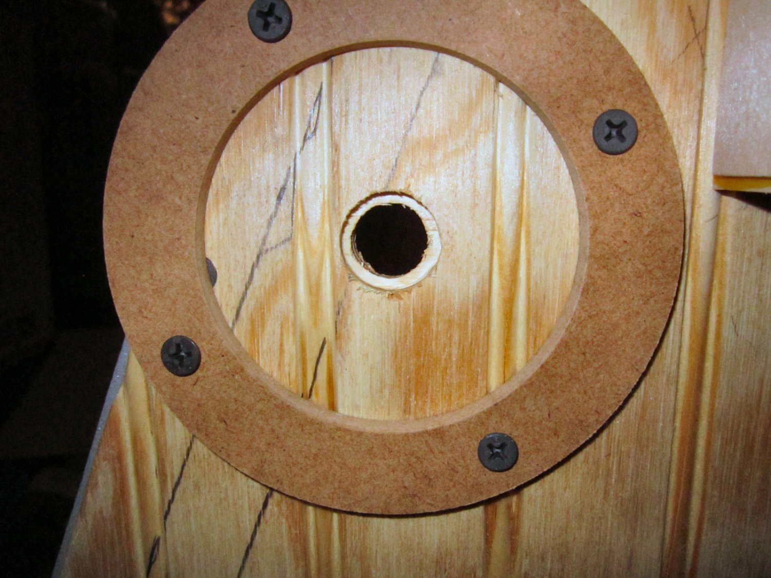
After setting the bit to cut about half way through the plywood, this is the new recess. Note that the router attachment is made from a somewhat flexible plastic and the threads on the Dremel nose are a little soft, so that the hole is not perfectly round, but fine for this application.

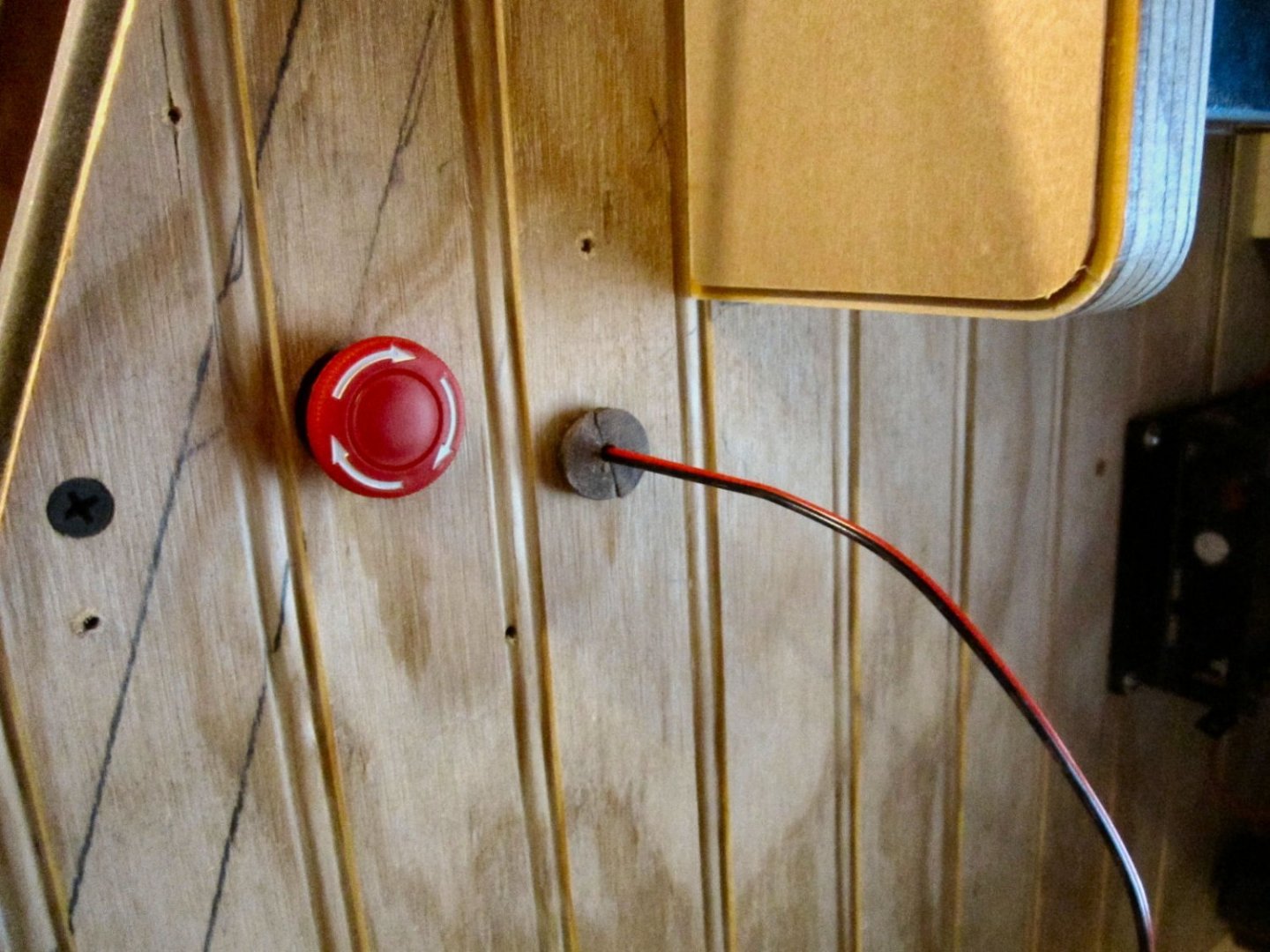
This shows the E-Stop button installed.
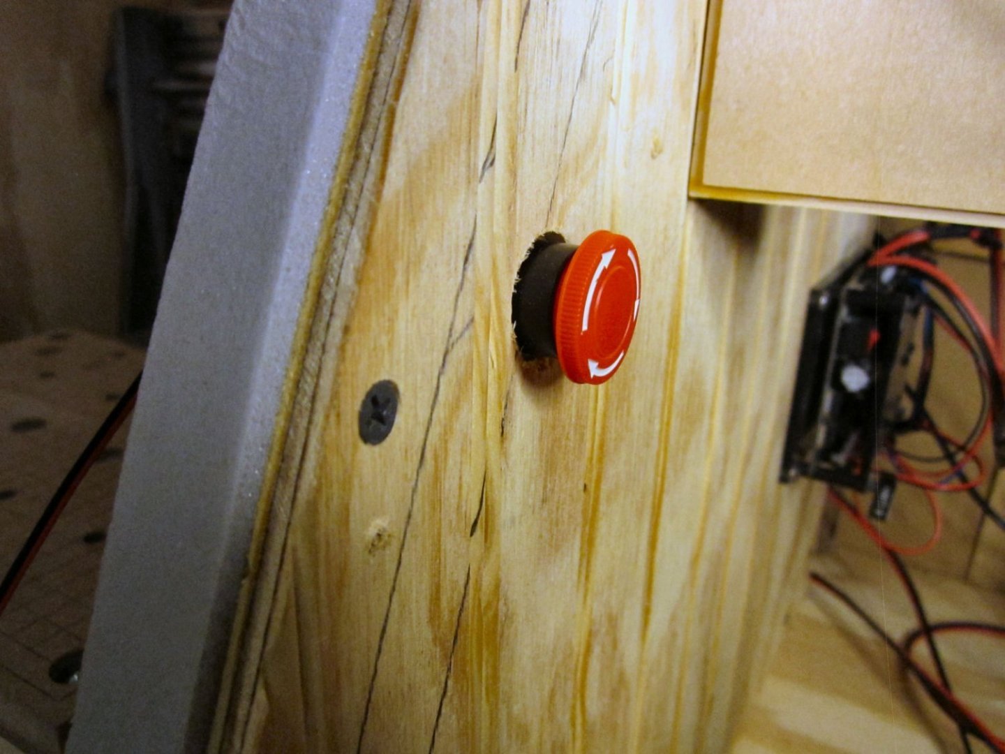
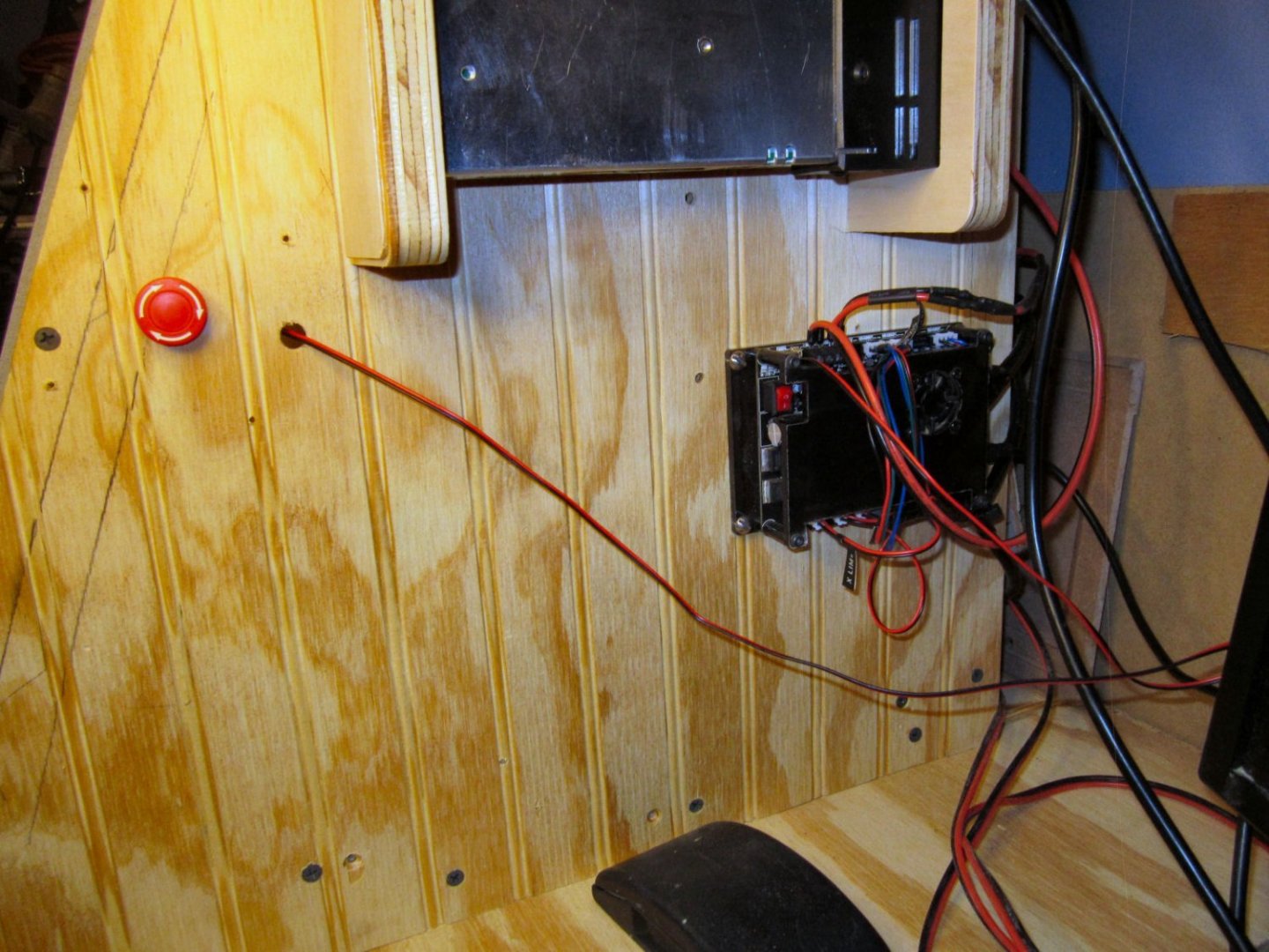
I wanted the button close to the front, but high enough so I wasn’t hitting it with my mouse or tools, so it is about halfway up the door edge cutout. This made the wires too short to go out the back of the enclosure, so I drilled a 3/8” hole by the switch to run the wire along the outside of the enclosure. I’ll neaten it up later. I may also machine a two part split plug for the wire hole, as I don’t want to permanently seal the wire hole, I may need to remove or replace the switch in the future.
I haven’t cut the hole for the vacuum hose yet. I’m waiting until I can order some hose and it comes in to see where the best location for the hole is. My wife objected to the notion of cutting the hose off our vacuum cleaner! Who’d have thought!
- Bob Fraser, mtaylor and tmj
-
 3
3
-
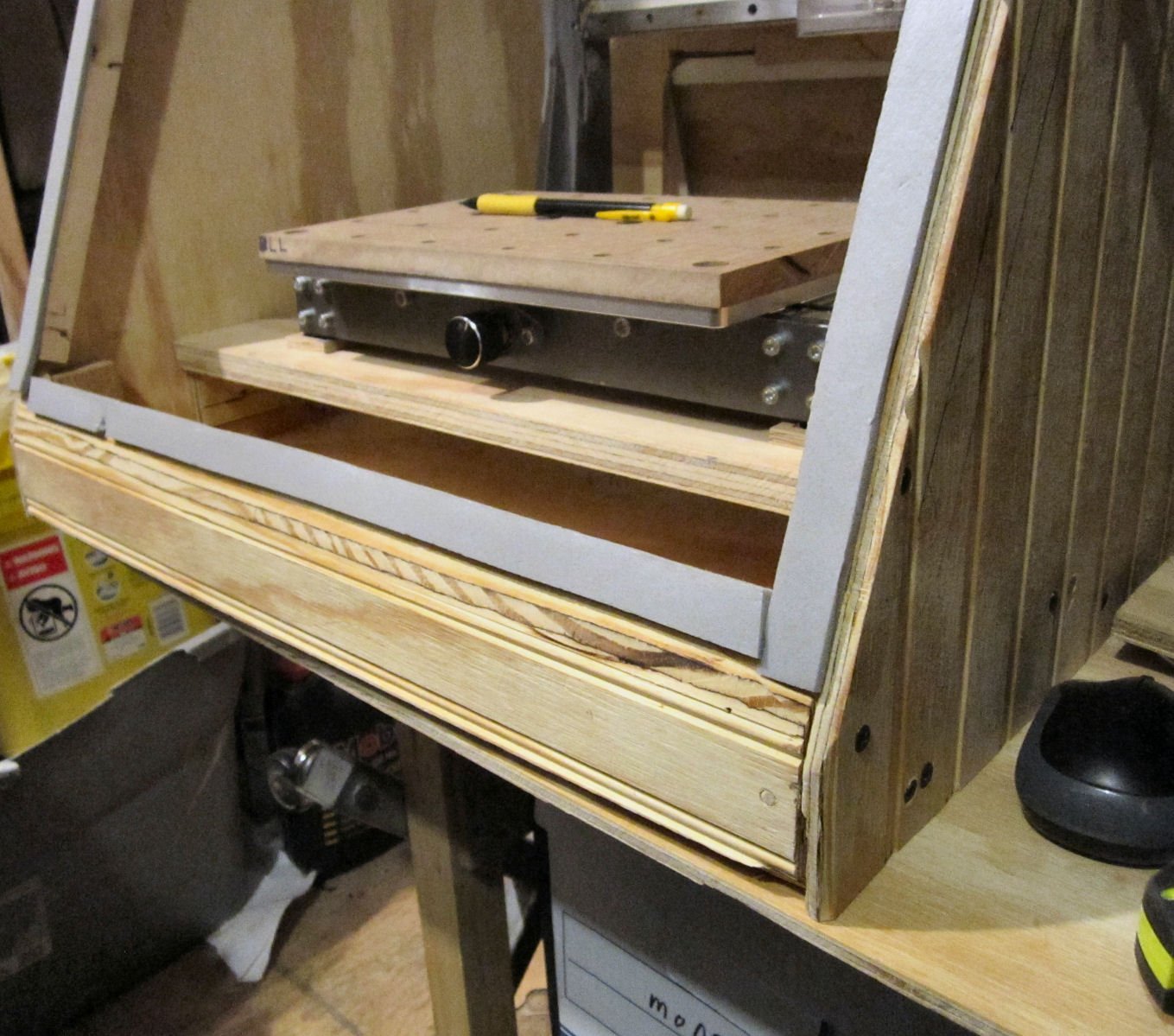
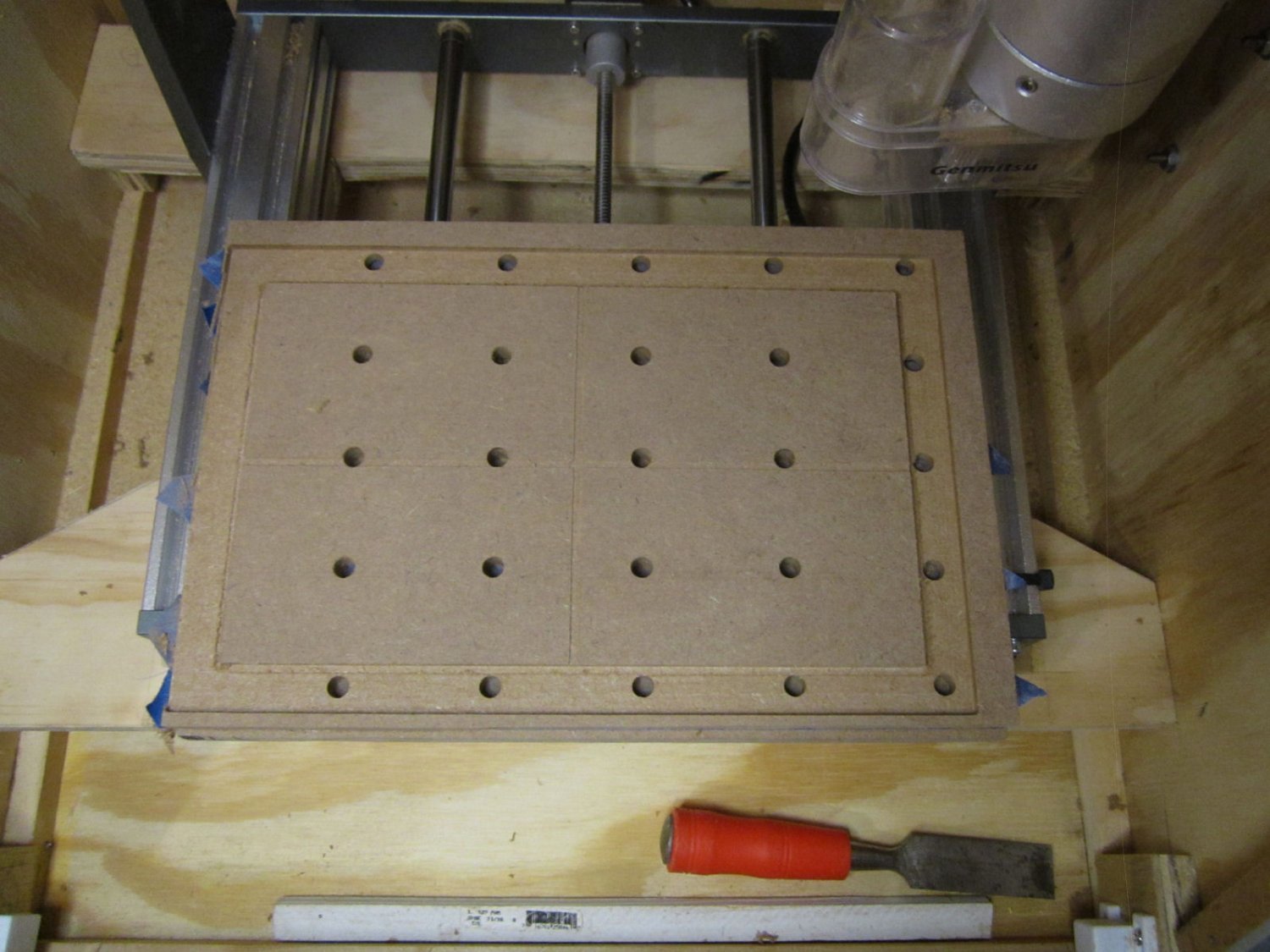
Part 021 – New Dust Shoe and Cutting a Calibration Block
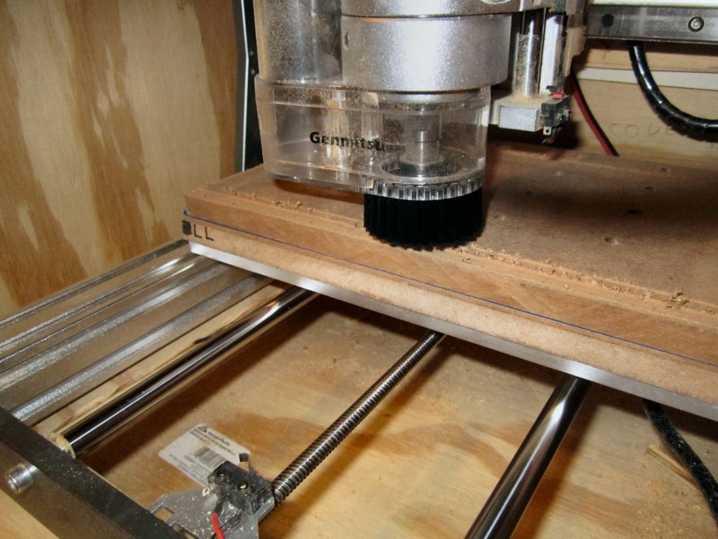
I tried out the 3020 Dust Shoe I received the other day what a difference!! I don’t have the permanent vacuum hose for the enclosure yet, so I removed the door and used the hose from my 3 gallon shop vacuum. I cut a piece, and no smell and very little escaped dust, as well as almost no sawdust in the bottom of the enclosure!
Here I’m doing a clearance cut, and you can see the buildup with no vacuum.

Here is the same cut, further along, with the vacuum on. The curlicues are pieces stuck to the edge, not left over chips that the vacuum missed. No the hose is not installed in the shot, I removed it so I could take the picture.
The shoe has the 20 mm long bristle brush piece installed. The 40 mm was too long for the 1/8” bit. It keep getting caught up in the tip. If I had been using a longer bit, the 40 mm would have been more useful. For the 1/8” bit, 25 mm bristles would be better, but that is not a length they sell.
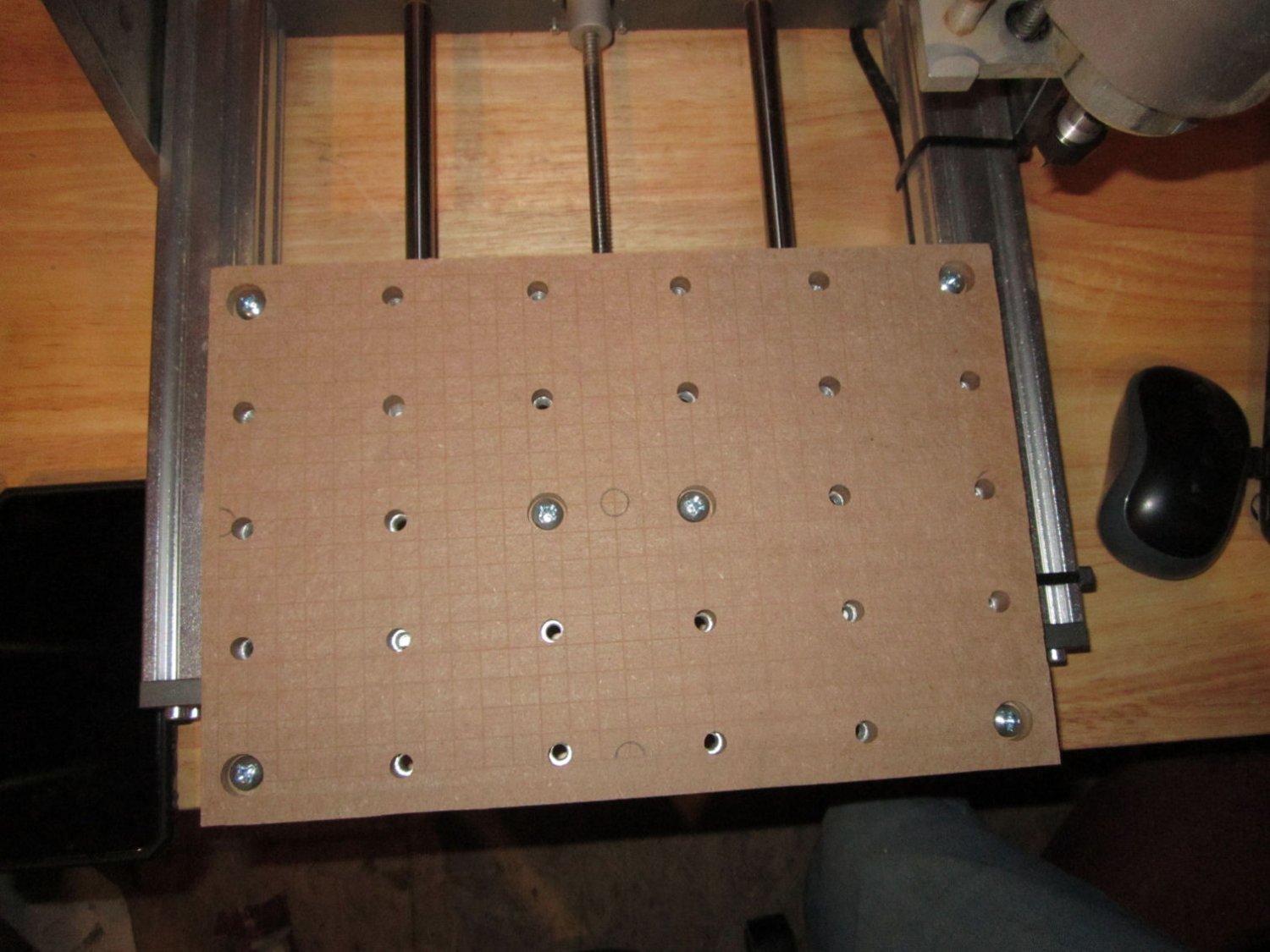
The workpiece I was cutting, was a calibration block for determining adjustments need to fine tune the stepper motors. GRBL has a section in the Setup Wizard where you move the X, Y, and Z-Axis then measure how far it actually moved, as opposed to how far you told it to go. Then you enter the actual movement and it calculates the amount of adjustment it will use in the future.
Rather than trying to use a dial indicator or a ruler to measure movement free hand, I cut a block 250mm X 150mm, then measured the actual size the block ended up being, using a 12” dial caliper. A 12” caliper is not as common as the standard 6” one, in most toolboxes, so a 150mm X 150 mm block would work for a 6” one. The clearance being cut above was around the outside of the block, so I could get the calipers in. I cut the clearance, leaving 0.1 mm around the outside of the block area, then as a last step, I had the router cut away that last bit.
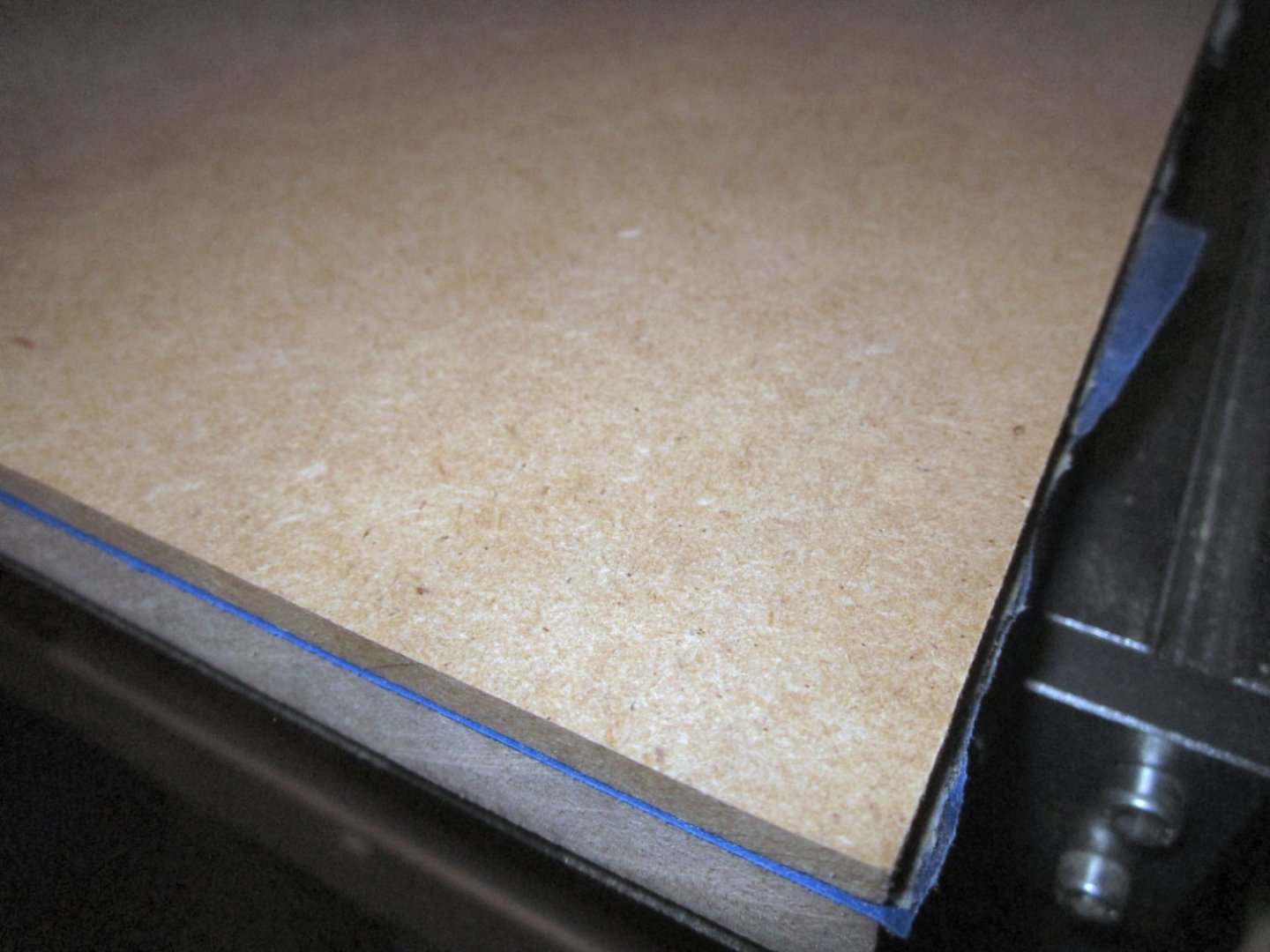
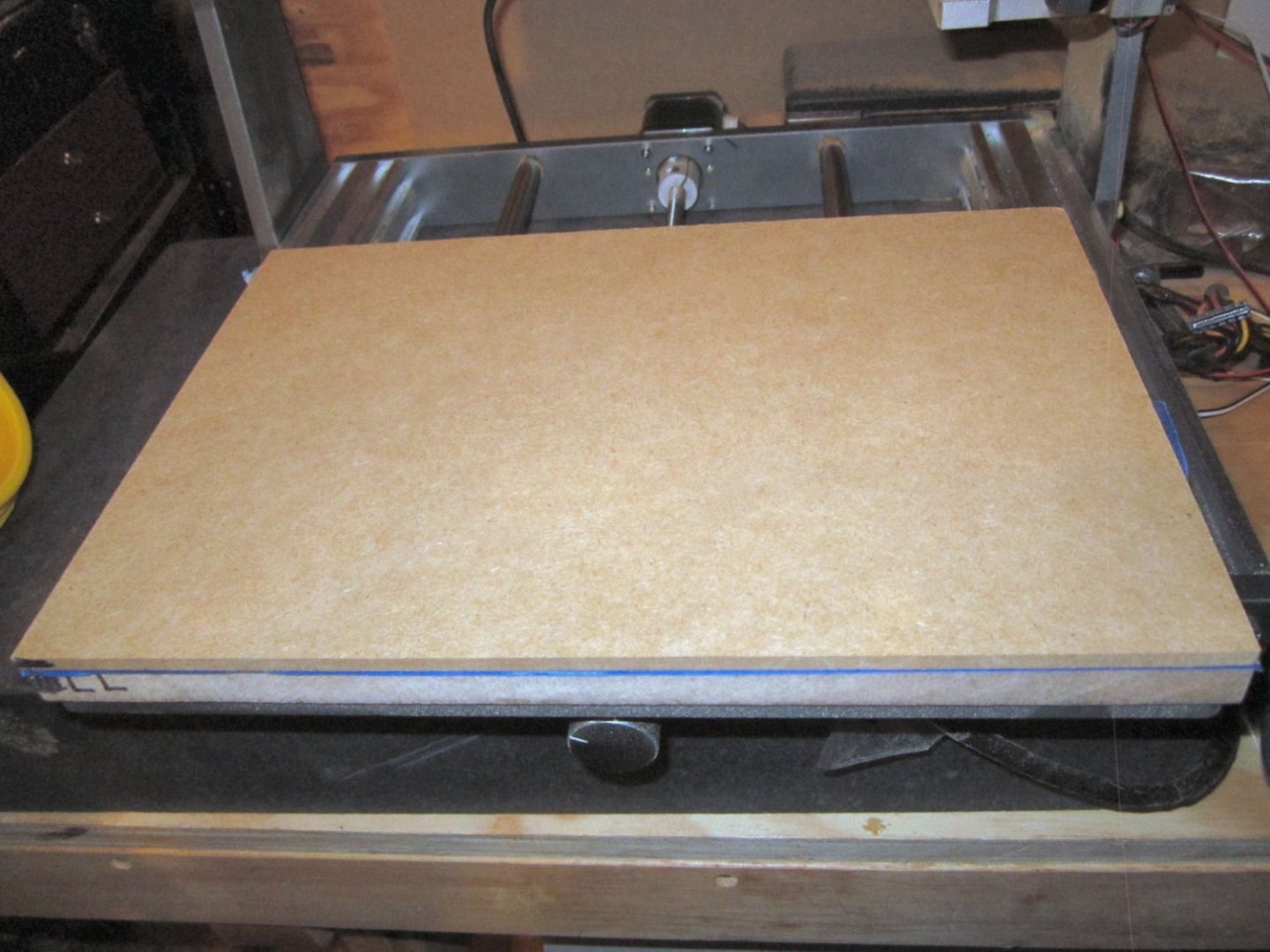
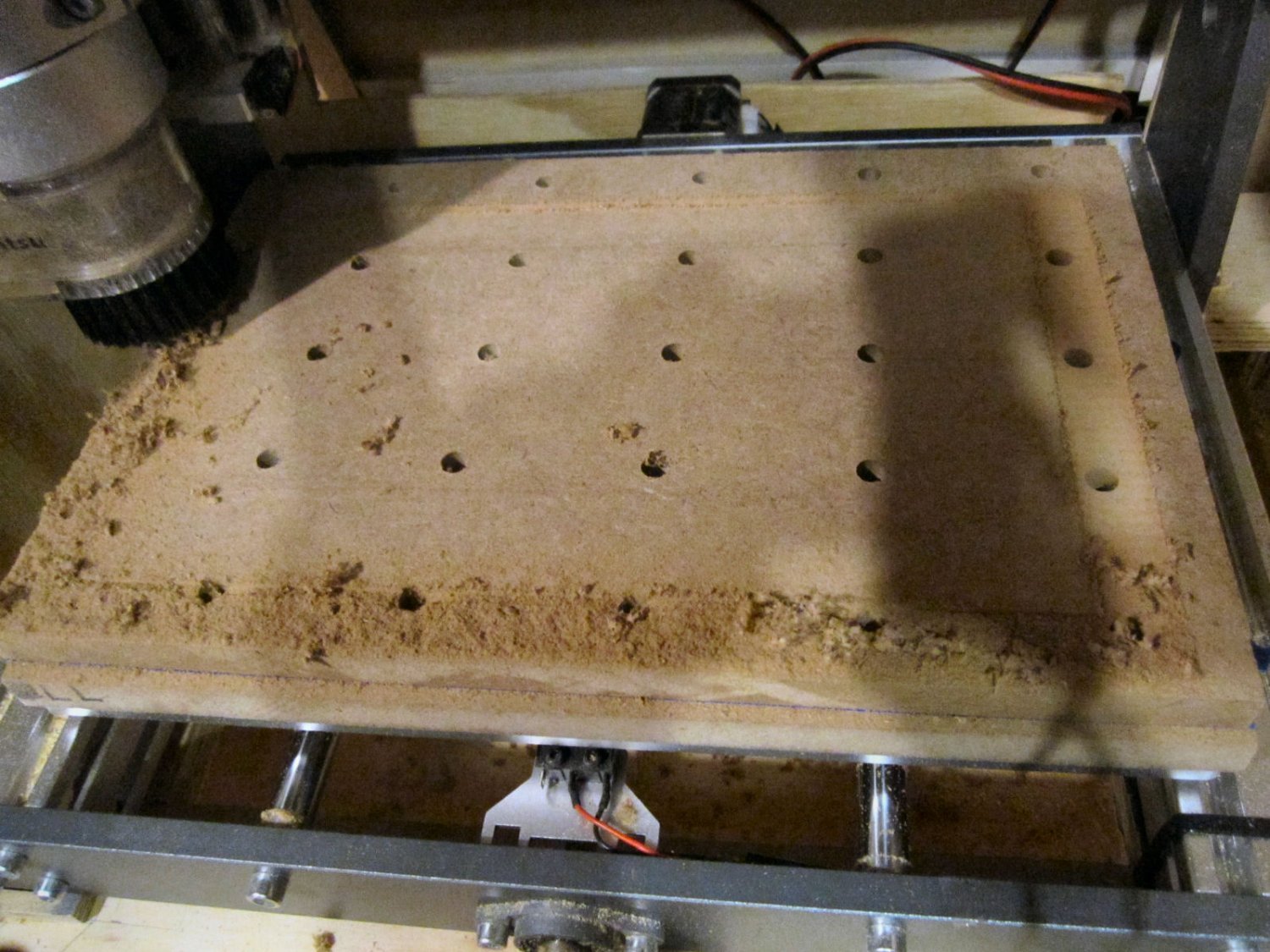
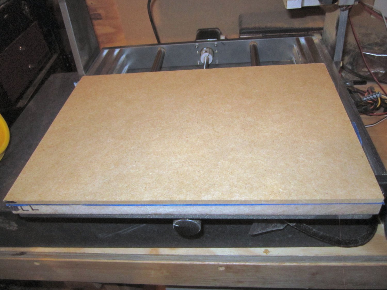
This is a picture of the finished block. The cross shaped lines are to give me alignment spots to insure the caliper was square to the sides. The holes are there because the workpiece is scrap from a failed spoil board (don’t accidentally hit a limit switch while vacuuming up chips!).

After all was said and done, the block ended up being 250.5 mm X 149.3 mm. After inputting those measurements, and the correction factor the program calculated, my parts should be more accurate, from now on. This would not make much difference on small parts, or carvings, but for larger mechanical type parts or a ship’s deck, keel, etc., it would. Yes, this isn’t a CNC Mill, but on the other hand, it doesn’t cost $4000 or $5000 either!
-
Joe;
As for what I plan to do with this router, make parts. I have spent several years designing the parts for a Chesapeake workboat (not full time, but finding all the info took time). I will use this to cut out the bulkheads etc. There are a few other models that I am also playing with. I also have projects for my model railroad, that this would be handy for. Most notably I have been working on drawings for a unique Santa Fe business car, and will be using this router and a soon to be acquired 3D resin printer to create parts for it. Santa Fe had several versions of this one type, and I hope to make one of each.
Also I enjoy CADing and playing with computers. So while it does take time away, I still get enjoyment from the process.
-
Part 020 Building An Enclosure – Part 4
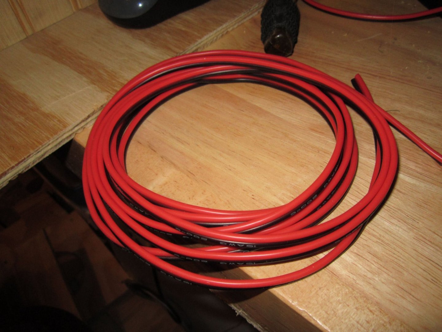
When I moved the controller to the outside of the enclosure, all the wires reached the new location, except the spindle motor wire. So I bought a box of Heat-Shrink Tubing, and a length of 16 gauge 2 conductor wire to lengthen it.
https://www.amazon.com/dp/B08PC1NKJ4?psc=1&ref=ppx_yo2_dt_b_product_details
https://www.amazon.com/dp/B07QM8249H?psc=1&ref=ppx_yo2_dt_b_product_details
Then I discovered that my 45 watt soldering iron was not powerful enough to solder 16 gauge wire, and my Weller 140 Watt soldering gun had a broken tip! I ordered a new tip for the Weller, and it should be in by Monday.
I continued the construction by enlarging the opening in the door to fit the Plexiglas panel I’d previously made, and gluing ¾” square strips behind the opening, for the glass to set into. The small dots are the heads of 18 gauge brads I used to hold the strips in position while the glue dried.
This picture shows the Plexiglas in place. The streaks you see are road rash scratches in the glass. I found this Plexiglas along the side of the road as part of a sign, that had fallen from a vehicle and been left. Plexiglas is expensive, and I can live with the scratches.
I have to come up with some method to hold the glass in place, but still be removable. I want it held firmly in place in case of something flying around inside the case. Until I come up with something, I nailed a scrap piece of quarter round along the bottom edge to hold it for now. The top of the molding is even with the top of the inner strip, creating a pocket for the glass.
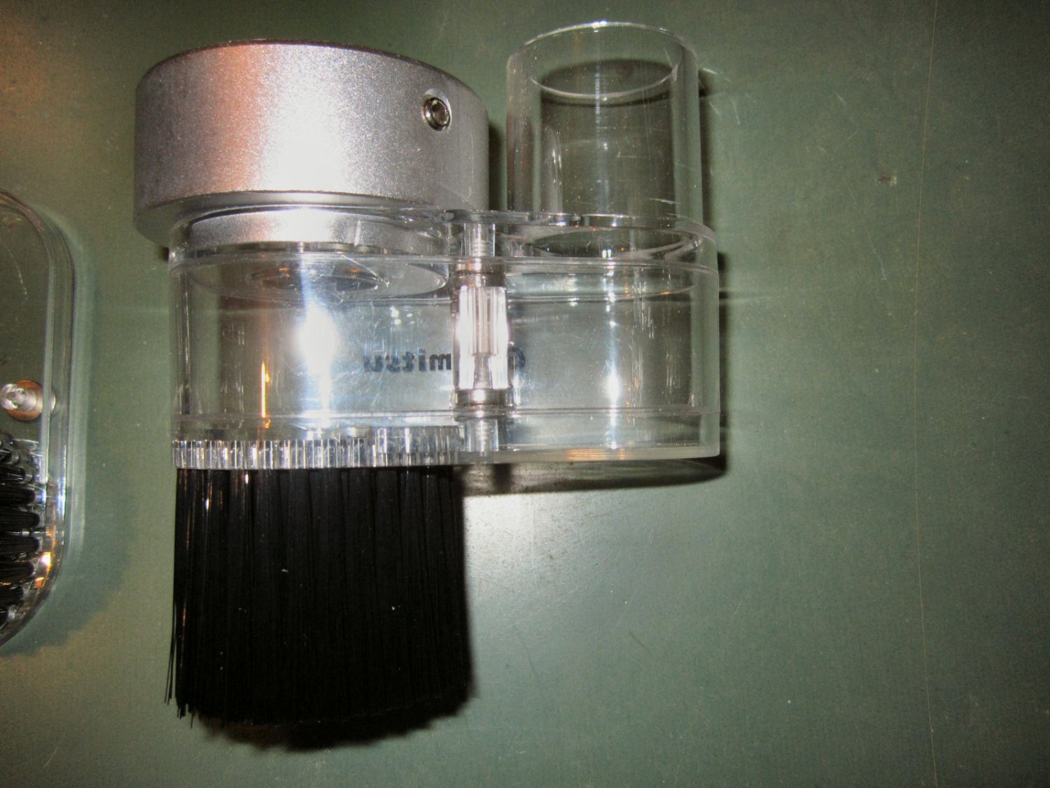
My new 3020 dust shoe also arrived. I’m glad I had to wait a couple weeks to buy one, as they just started offering this one. I had planned to buy one made for the 3018, and adapt it somehow. This one is much better.

It has an aluminum ring that is secured to the bottom of the motor with two setscrews. There is an inner ring that the screws bear on that presses against the motor housing, so it is not scratched by the screws. This is a nice touch.
The body of the dust shoe comes in three parts, that are held together by magnets. Each piece has a tongue and groove mating surface to align the parts.
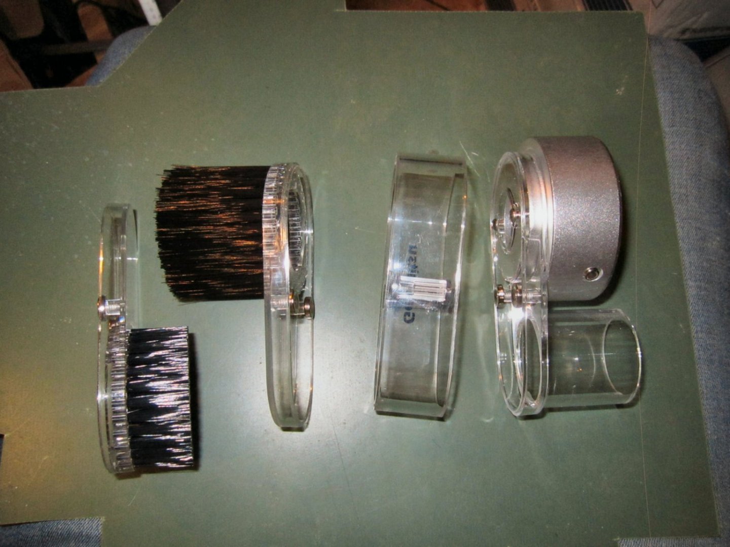
The top has the mounting adaptor, as well as the nipple for the dust collection hose. The dust collection nipple has an inside diameter of 1 ¼” and an outer diameter of 1 ½”. This allows you to use either a 1” , or 1 ½” ID hose.
The middle piece can be removed to allow you to get to the bit, the collet nut and the wrench slots in the spindle, without having to remove the whole shoe.
Two pieces are supplied for the bottom plate, with the collection bristles. One has 40 mm long bristles (the bottom of the bristles come out just a little lower than the tip of a typical bit), and the other 20 mm bristles. For now they also offer a replacement 20 mm bristle bottom piece, that you can buy separately. I hope they will have a 40 mm replacement, in the future.
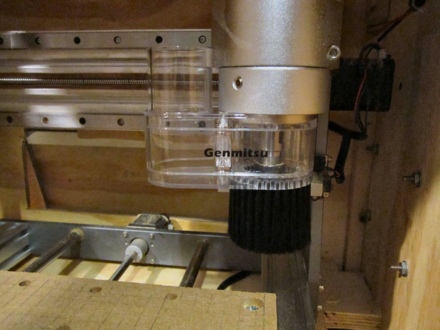
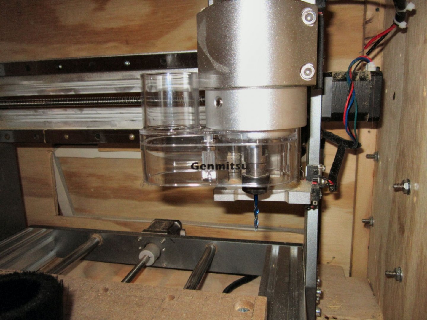
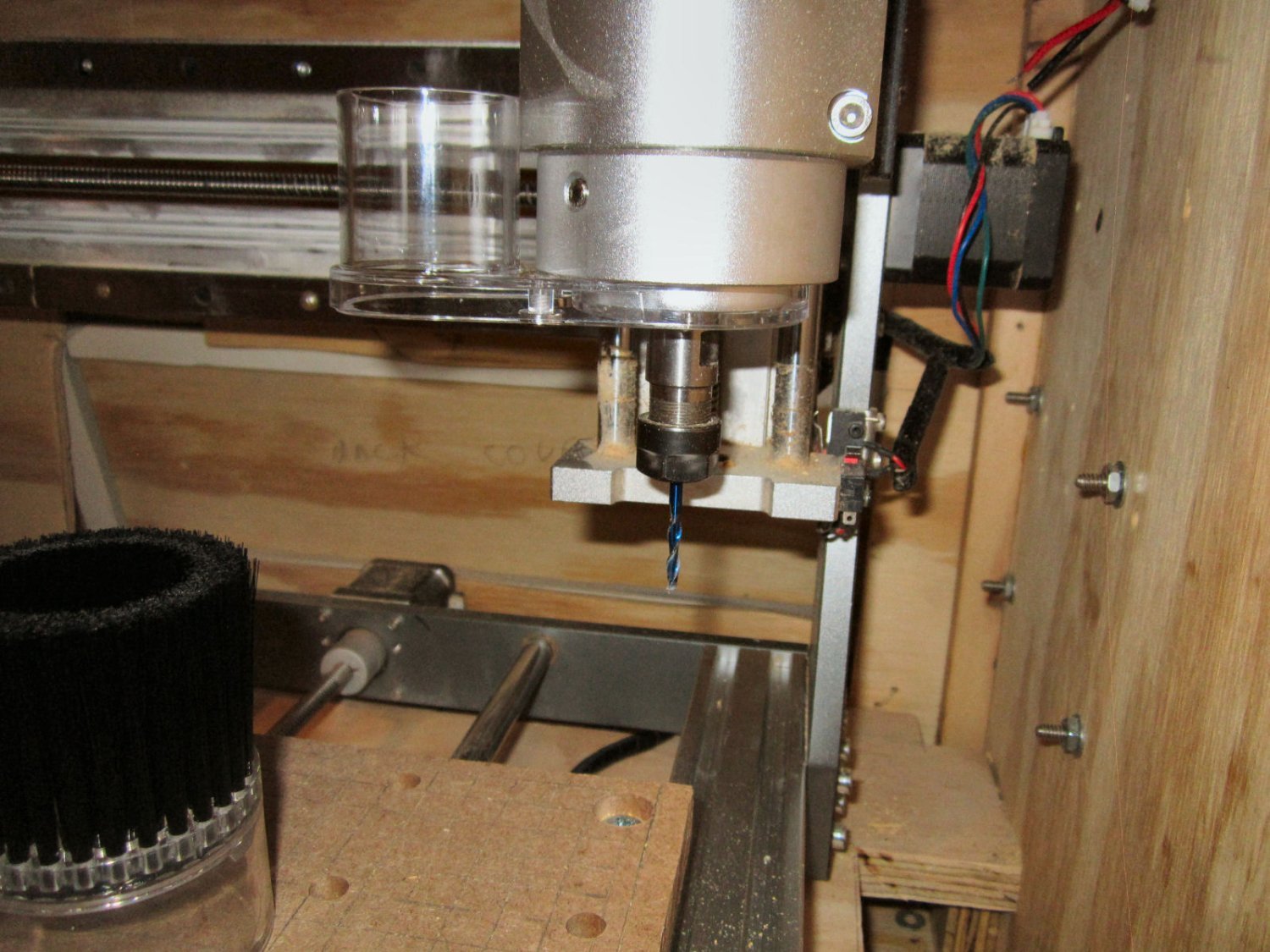
Here is a photo of the shoe installed on the spindle motor. I plan to have it mounted as shown with the vacuum inlet to the side rather than at the more typical front. This gives me more clearance from the enclosure door for the hose. You can still reach both screws with it mounted this way, though the back one is a little tricky to get to.
This picture shows it with both bottom pieces removed for collet access.

This one shows it with just the bottom removed. You would do this so you can see to position the bit at the workpiece origin. Once everything is setup you can raise the spindle and replace the bottom.
For now, I will have to wait to see how effective it is, as I have to wait until my next pay check to order some vacuum hose, as well as making some sort of adapter at the enclosure wall.
-
-
You might want to hit all that exposed brass with some type of clear coat, to keep it from tarnishing in the future.
- lmagna, mtaylor, Keith Black and 5 others
-
8
-
Part 019 Building An Enclosure – Part 3
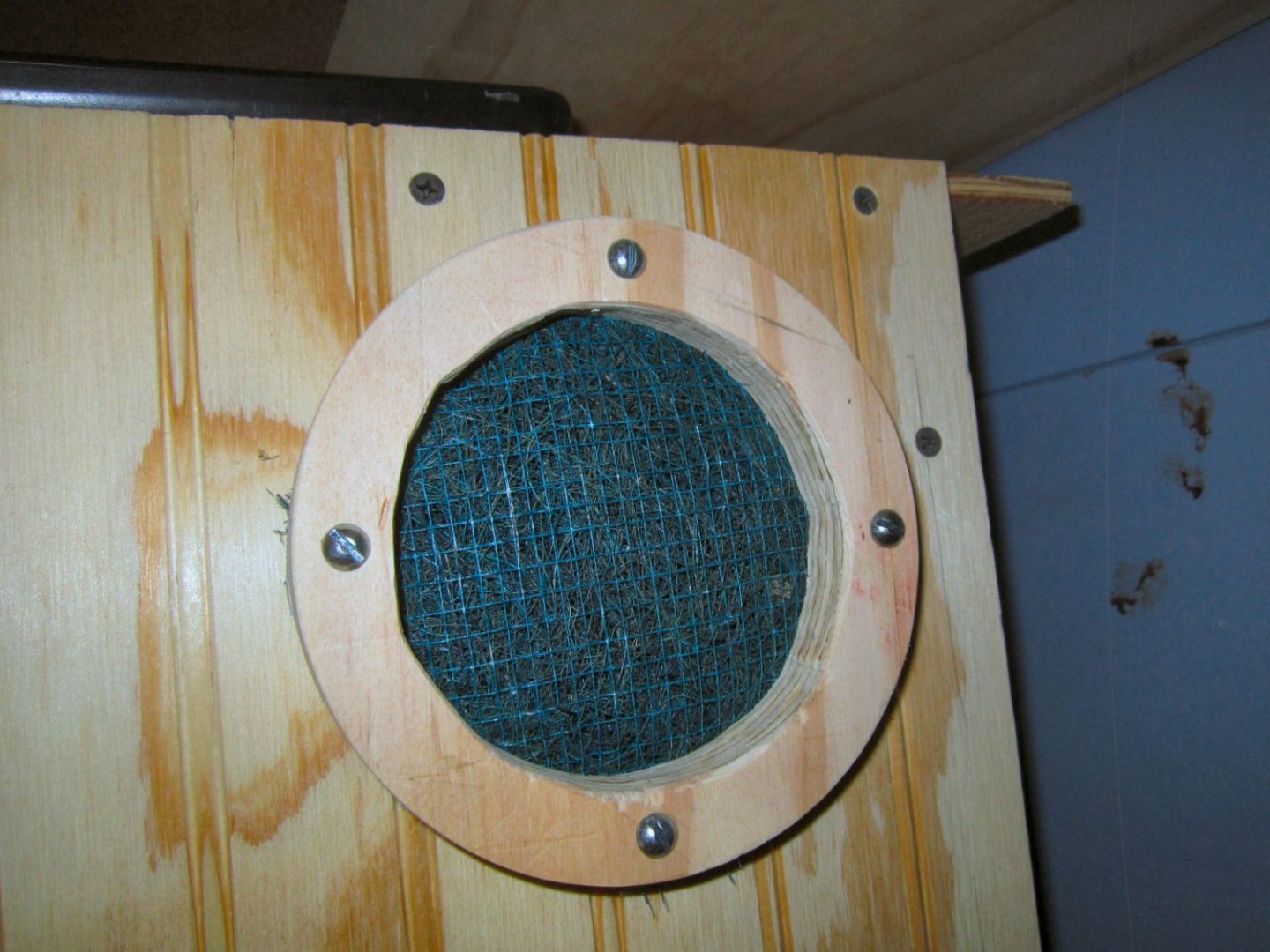
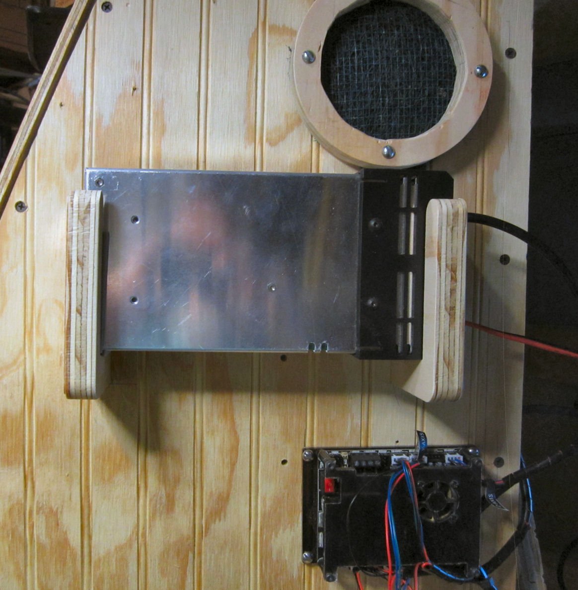
I got the longer screws for the filter ring, and have the filter installed.
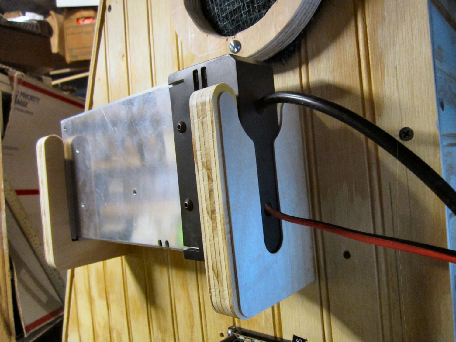
I cut out the power supply brackets, using ¾” plywood. The center grove is 1 ½” wide, for both brackets. The plastic case on one end of the PS is a little less than 1 ½” over the screw heads, and the metal case is about 1 1/8”. The groove for this end is wider than this so I can pad the inside with 3/16” weather stripping, to cushion the PS.
When I went to install these power supply supports, I discovered that the power supply is quite slippery! So I cut out covers from 1/16” hobby plywood for each bracket to lock the supply in place. The cover on the right has a relief for the AC and DC cables.
I then glued the covers on the outside ends of the supports.

I mounted the supports from the inside with the same 1 ¼” drywall screws I used on the case. Then I attached the 3/16” weather stripping on the support for the metal end of the supply. This keeps it from rattling around.


-
Part 018 Building An Enclosure – Part 2
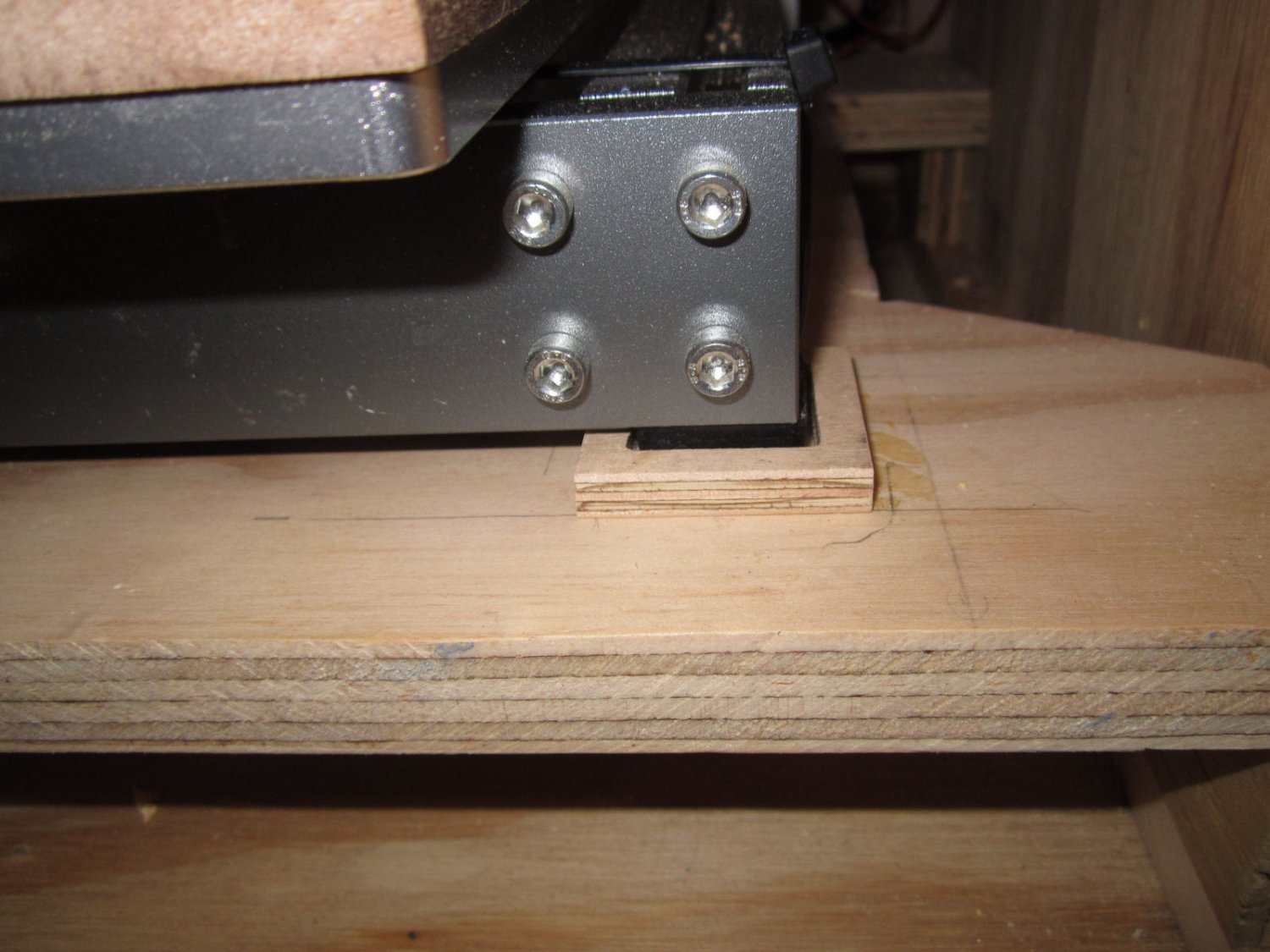
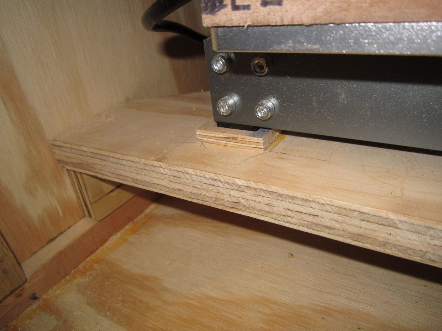
Next, I designed the little “Coasters” to hold the router feet securely. The feet are 3/8” high and about 7/8” wide. I designed the coasters using some of the leftover 3/8” plywood. The center is routed out ¼” deep with a ¼” wide rim. The center depression is 1 ¼” on a side, allowing for a little slop to aid in getting the router in place. This leaves the coasters 1/8’ lower than the frame, with the feet inserted.

This picture shows one of the coasters glued in place. I positioned the router, to determine the correct position for this one, and let the glue set, with the router set down on the piece.
After the glue dried, I positioned and glued the second one down. Once this dried, This locked the router in position. After this, I positioned and glued down the back ones.
These pictures shows the router set into the two front coasters.

Next I designed a rim to clamp a filter in place to allow air into the enclosure. The air will be pulled in by the vacuum, used to clear the debris from around the bit. The ring is ¾” plywood with a 4” inside diameter, and a ¾” thick rim. I also put 4 mounting holes for #10-24 machine screws in the design.
Next I installed it on the right hand upper side of the enclosure. This keeps it away from the areas that I’ll mount the control box, and power supply.
I was going to use my router to cut the hole in the center, but naturally, I can’t find the router! So I cut it out with my saber saw, and yes, I only have middling skills with it, and I scared the ring.

When I went to install the filter material, I found that the screws were too short, so I’ll have to get some longer ones.
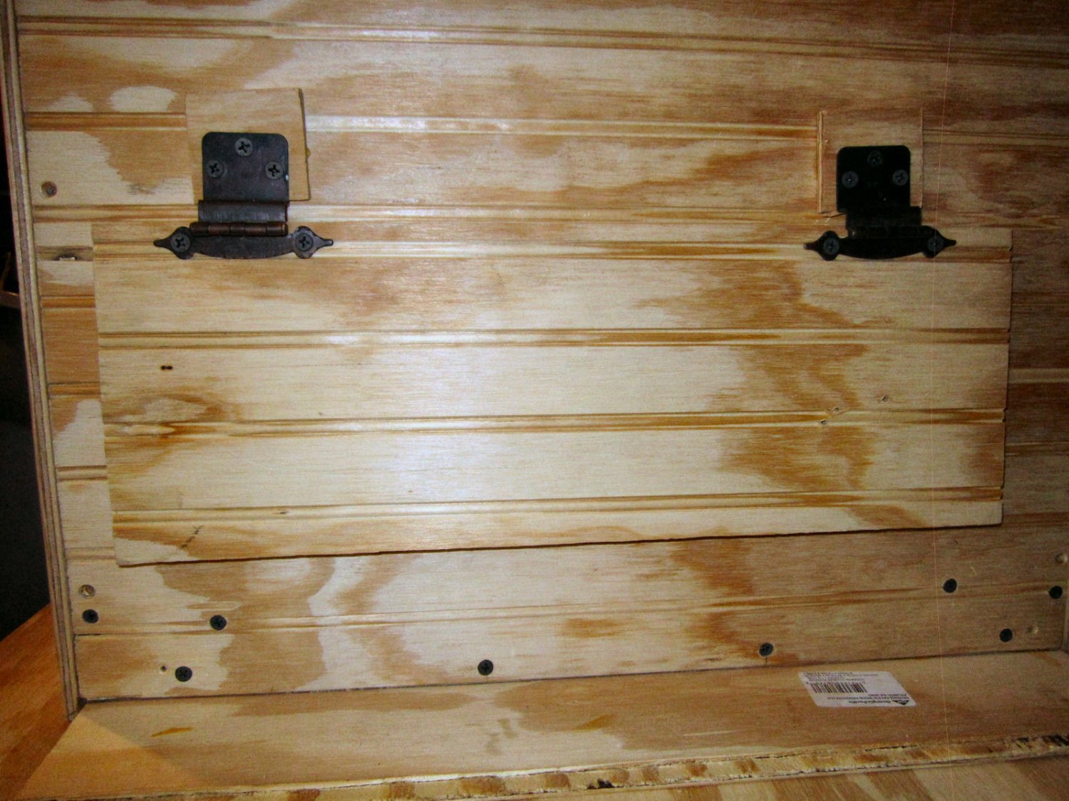
I installed the back door.

I found a couple of offset cabinet hinges in my junk drawer. This allowed the door to sit flush, then I added 3/8” pads under them so I could put weather stripping on the door.
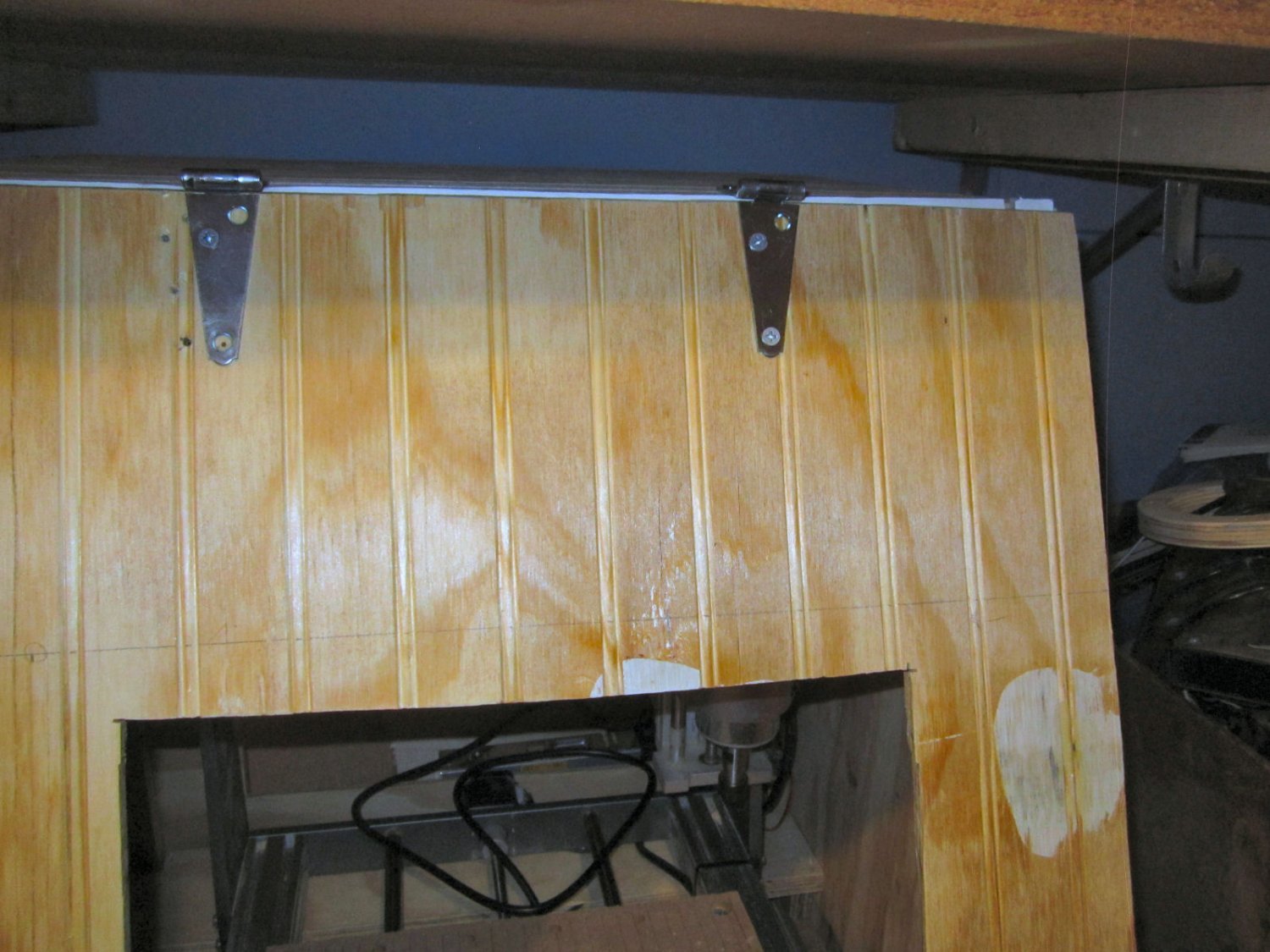
I also weather stripped the front door. To do this I had to change from the 2” strap hinges, I first used, to 3” ones. The 2” ones didn’t have enough reach with the weather stripping added.

Instead of hinging the front, I decided to just have the magnetic door latches hold it in place. To keep it from shifting I put a couple of small nails, loosely fitted, at each end. The nails are not permanent. I will pick up some bamboo skewers and use them to make locating pins.
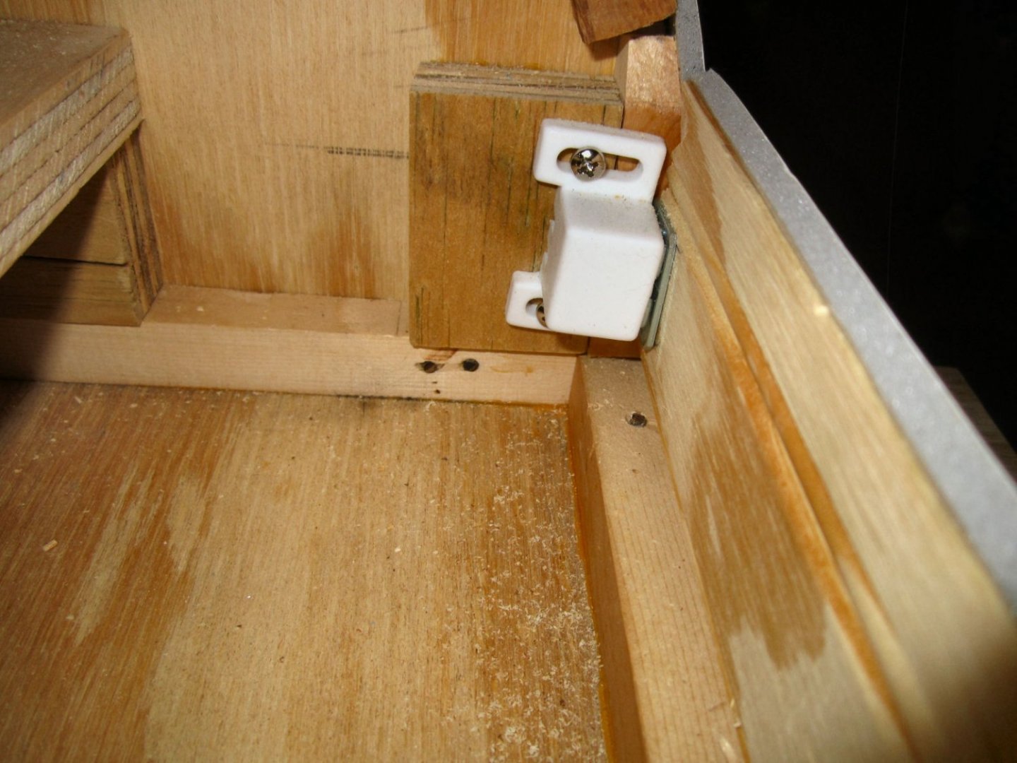
The enclosure doesn’t need to be air tight, just fairly dust tight. The eventual vacuum system will create a negative pressure to pull air in and keep the dust in.
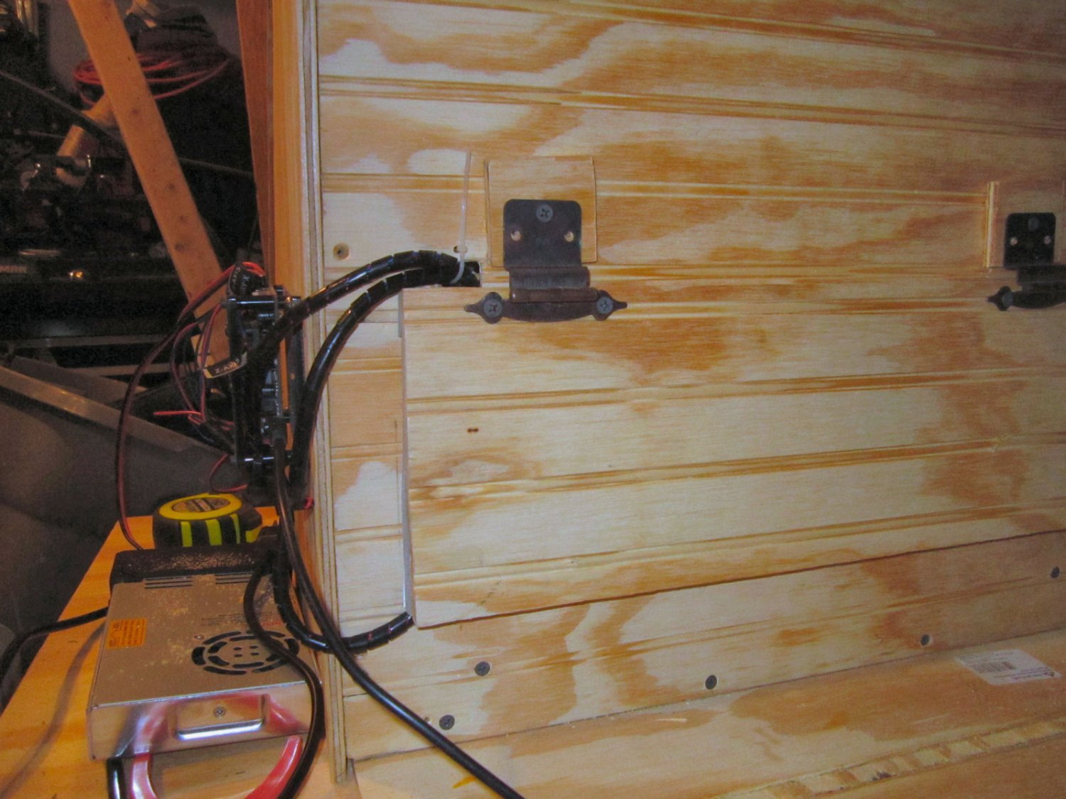
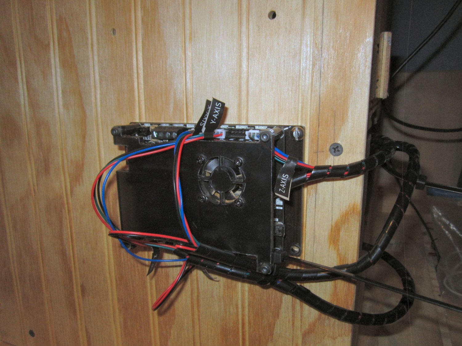
The next step was to move the controller to the outside. All the cables were long enough, barely, except the spindle motor wire. I have a roll of the proper size wire coming in, in the next couple days. Thank you Amazon Prime! No local stores had the correct wire. As a note, I had to look closely at the wire specifications! Many of the available types of this size wire are only rated at 12V. The wiring supplied with the spindle is rated at 300V, and the power supply has a 48V output.
To get the cables to the outside, I cut groves above and below the back door, then chamfered the edges. The small holes are for cable ties.


You can see the cable tie for the upper bundle in this shot.

The Z and X-Axis cables come out the top, the Y-Axis the bottom.
The controller is mounted with #10-24 machine screws 1 ½” long. When the rest of the enclosure is done, I’ll add a rim around the controller to protect it from bumps, and bangs.
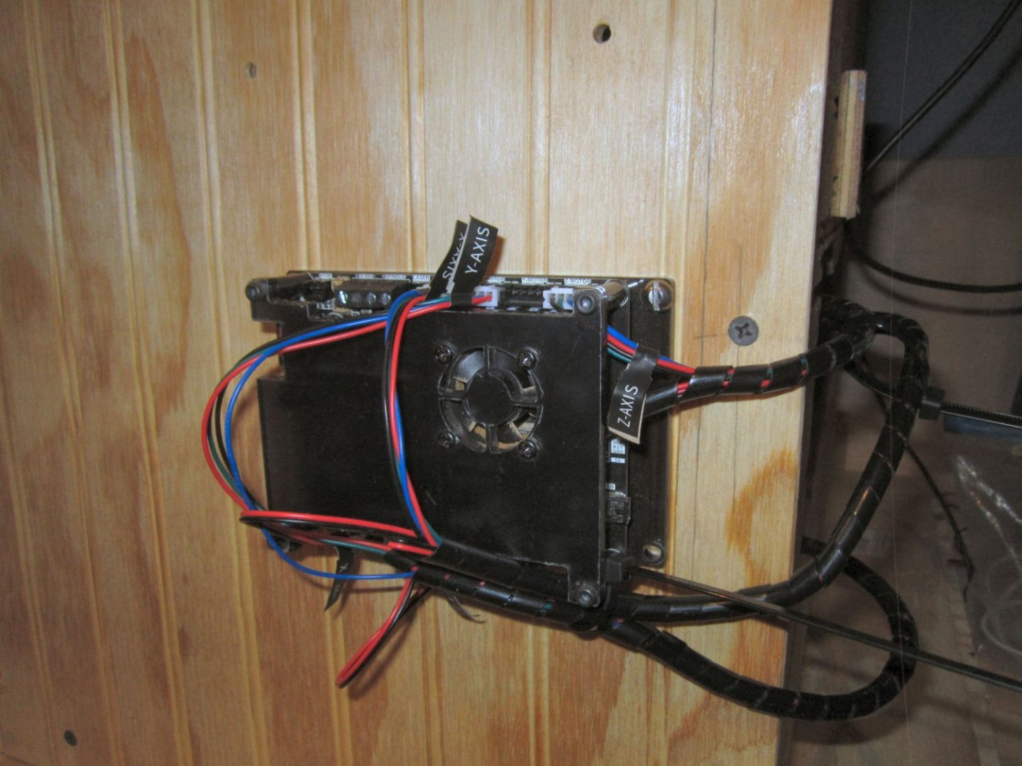
Not the neatest, but it will do.
The power supply will be mounted above the controller. I’ve cut out the PS brackets, and will get more done Friday. I cut the PS brackets by moving the controller back behind the enclosure, and even with the back door open and the Plexiglas taped in place, the noise level during routing is greatly reduced!
Part 19 will continue the construction.
-
Part 017 Building An Enclosure – Part 1
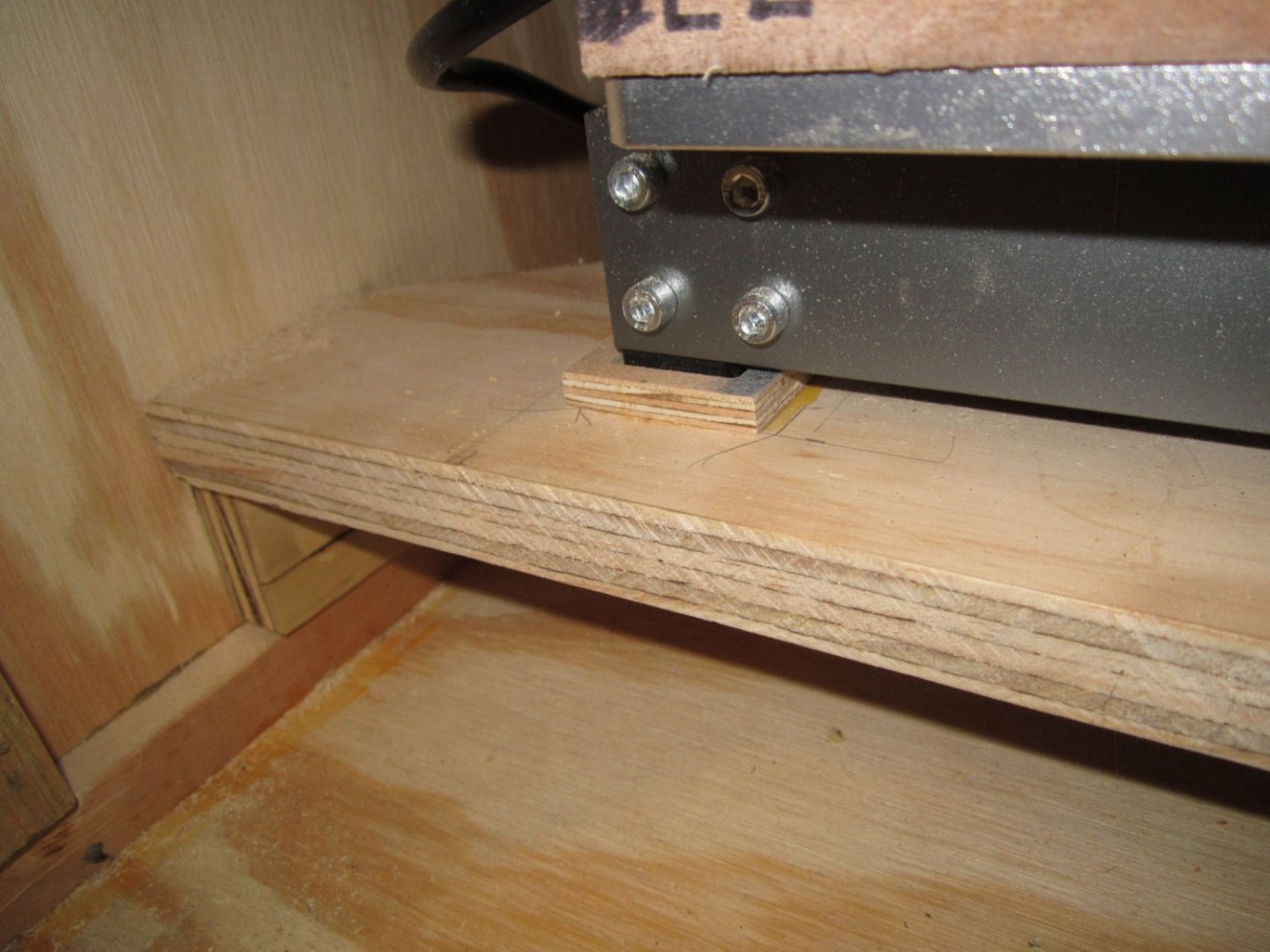
I’ve started building the enclosure, finally! I had a design finished, but then decided on some improvements to that design. After having the router on just my workbench, I found myself having to tilt it back after each job, to vacuum under it. My original enclosure design had it sitting on the bottom of the housing, meaning I’d have to do this, with less access and room. So I decided to raise the router up on a shelf, and cut the shelf so the sawdust and chips could fall past it, thus allowing me to remove the debris without having to move the router.
Some of the things I want to cut are larger than the bed of the machine, and you can do this by paneling. You put a longer piece on the bed, cut as much as you can, then slide the piece along and cut another area, etc. Tricky, but doable. I would need to do this to cut a keel piece for a plank on bulkhead model, for example. Bulkheads can be cut in one go, for any model I’m likely to ever build, but a keel may be 15” to 30” long for that model.
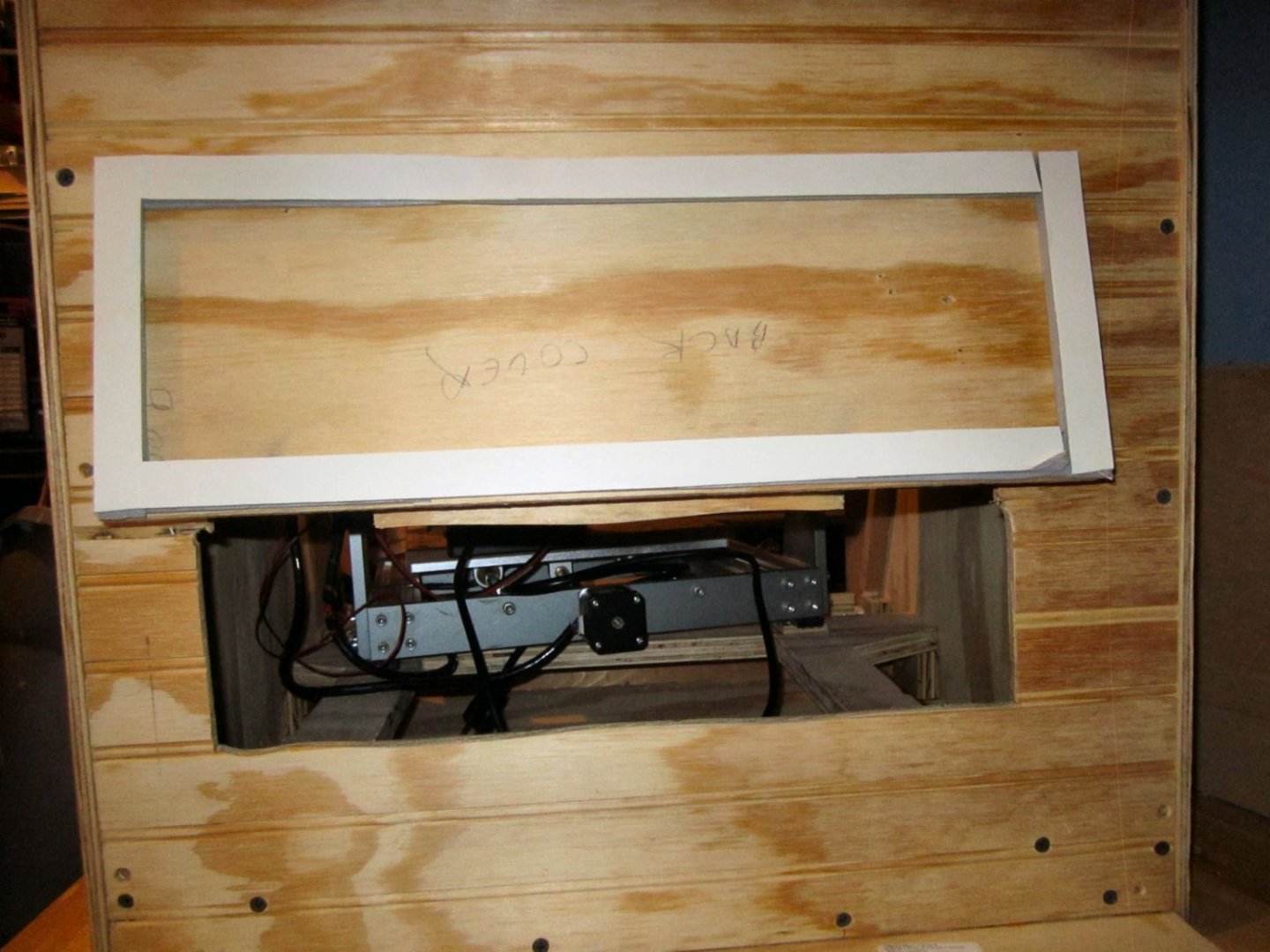
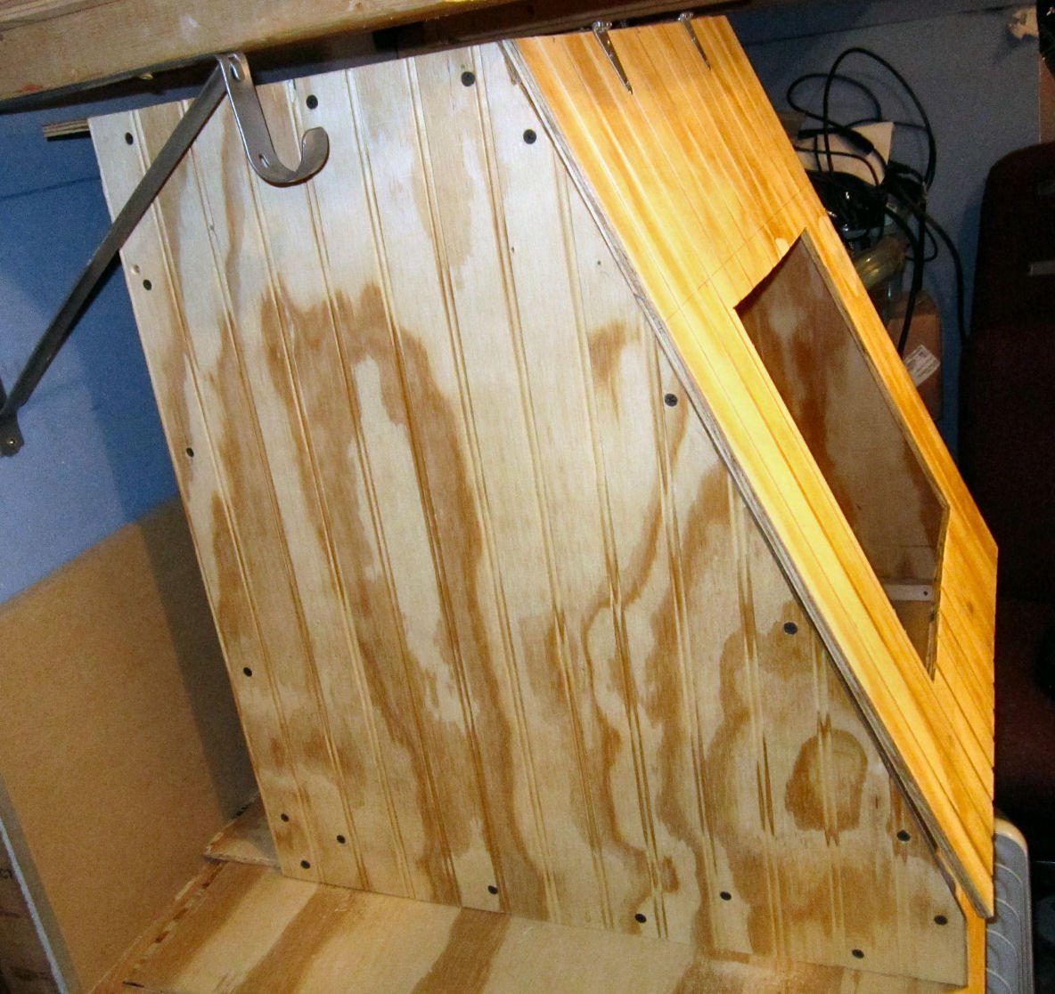
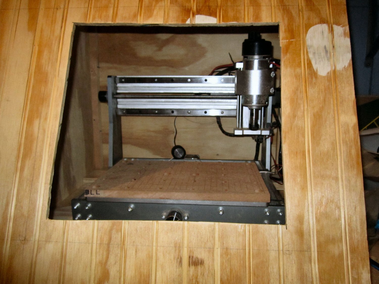
To allow for this I extended the window opening on the door so the bottom edge was below the table level, and the sides extend pass the edges of the table. Thus I can simply remove the window, so work pieces can pass through the opening. Once I get everything assembled, I’ll cut an opening in the back to allow for the same thing, and put a door over that cutout.
I left the case overly tall, so that I have room to add a light and a vacuum hose for removing chips right at the bit area. I also shortened the depth of the enclosure from 24” to 21” so it would not overhang my workbench.
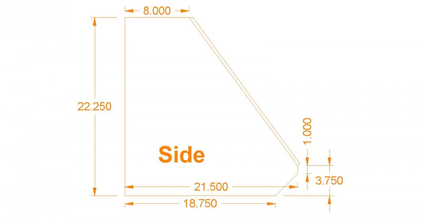
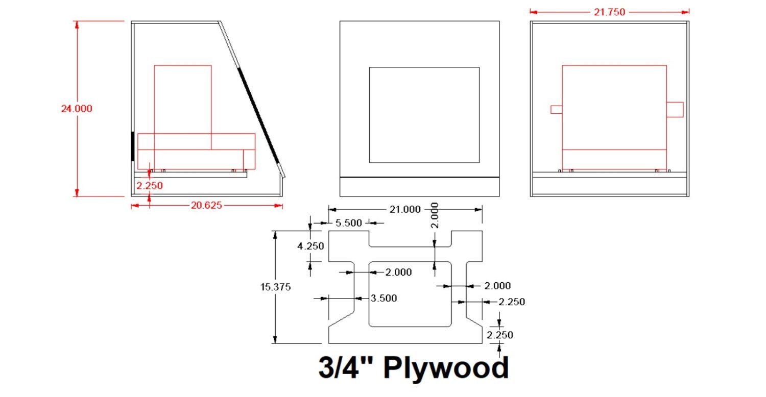
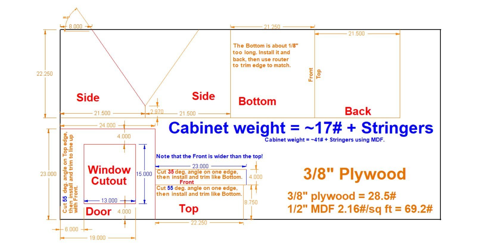
Here are diagrams of the enclosure and the shelf. The enclosure is 3/8” plywood, and the shelf ¾” with a 2.25” gap under the bottom of the shelf for vacuum access. I would have liked a little more of a gap, but the router (with a theoretical maximum work piece on it) was getting too close to reasonable door positions, so I had to compromise.
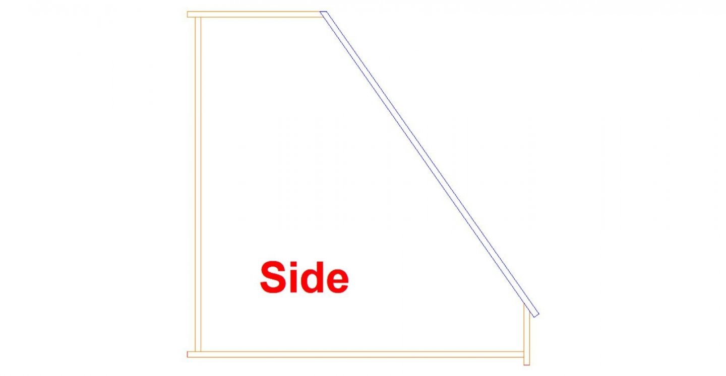
The drawing below shows the enclosure with a rough router and work piece outline, as well as the shelf. The dark areas are the openings for the back panel door and the window in the door.
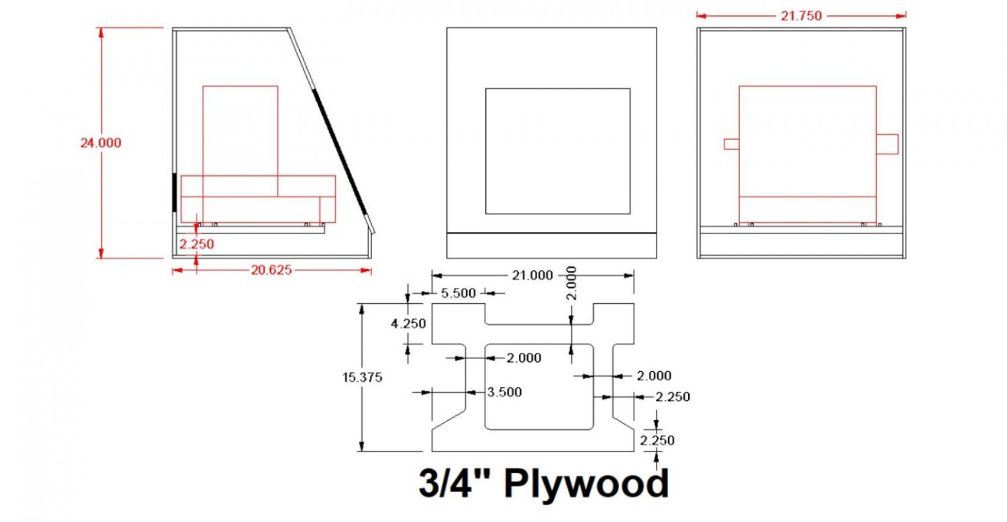
The little squares by the router feet represent hollow square “Coasters” I’m going to machine and glue onto the shelf to keep the router from moving around. The shelf will be supported with 1 ½” wide ¾” plywood strips under the outside tabs. These will be glued and screwed to the sides. I may leave the shelf removable, I haven’t decided.
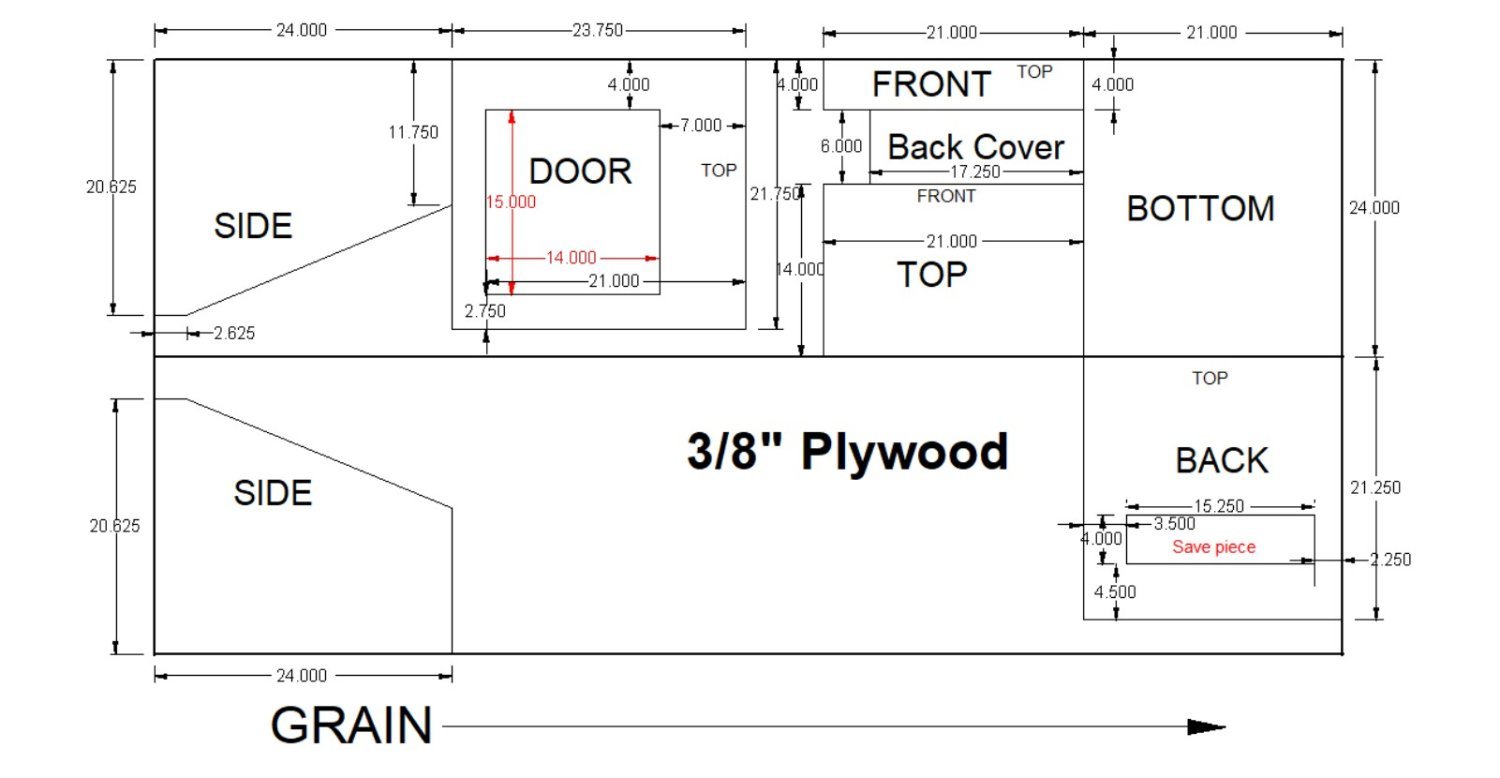
This drawing shows the parts laid out on the 4x8 plywood sheet. I chose 3/8” plywood to keep the enclosure light. It will be stored on a shelf above the workbench, and moved down when doing jobs, so I can watch it in case of a problem. I used ¾” square strips I ripped from a 1X12 scrap, for the corners (glued and screwed). I used #6 1 ¼” drywall screws, with the holes predrilled with a #6 countersink bit. The store did not have 1” ones. I used a Dremel with a cutoff wheel to trim the tips that protruded inside. The cheapest flat 3/8” plywood I could find was made to be used as wainscoting, at $25.
The back is cut to fit between the top and bottom sheets. The bottom and top sheets are cut overlong, and I’ll use my hand held router to trim them flush, once everything is assembled. My circular saw skills are only moderate, so this allowed me to have some wiggle room. The line down the middle of the sheet (lengthwise) is due to the fact that I had the sheet cut into two 2x8 pieces, so I could fit it in my car.
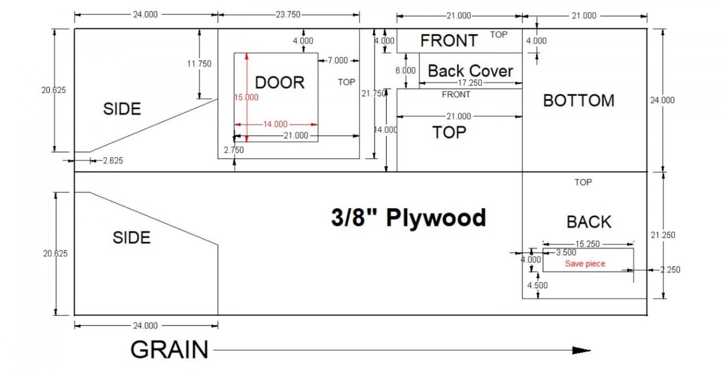
The front piece is also overlong, and will be trimmed to fit. This piece will be hinged to fold down, to allow for access to the feedscrew knob, and vacuum access. I have a couple of magnetic cabinet latches to hold it in place, as well as it being trapped under the door.
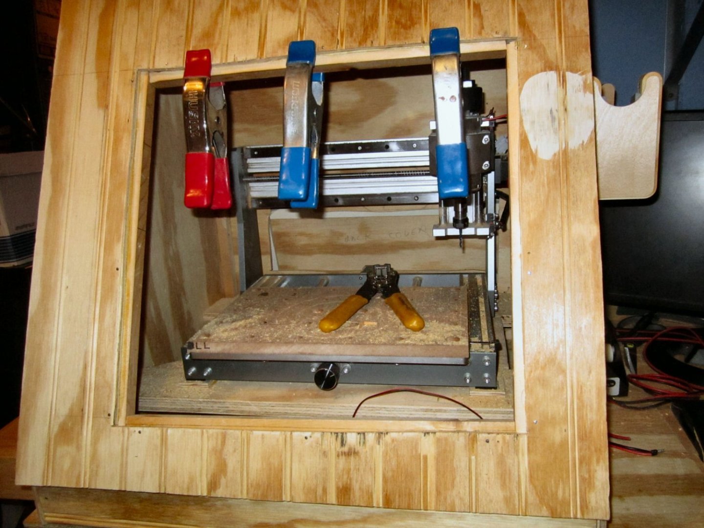
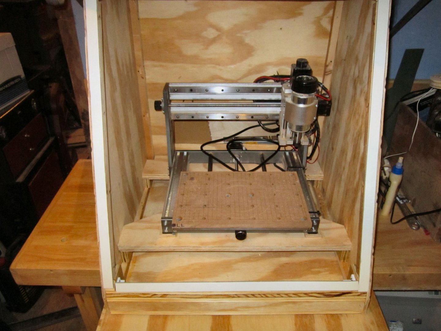
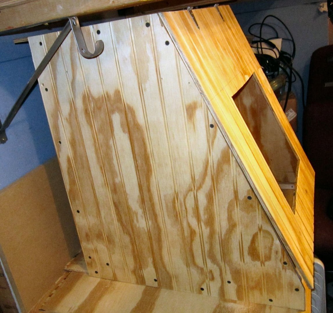
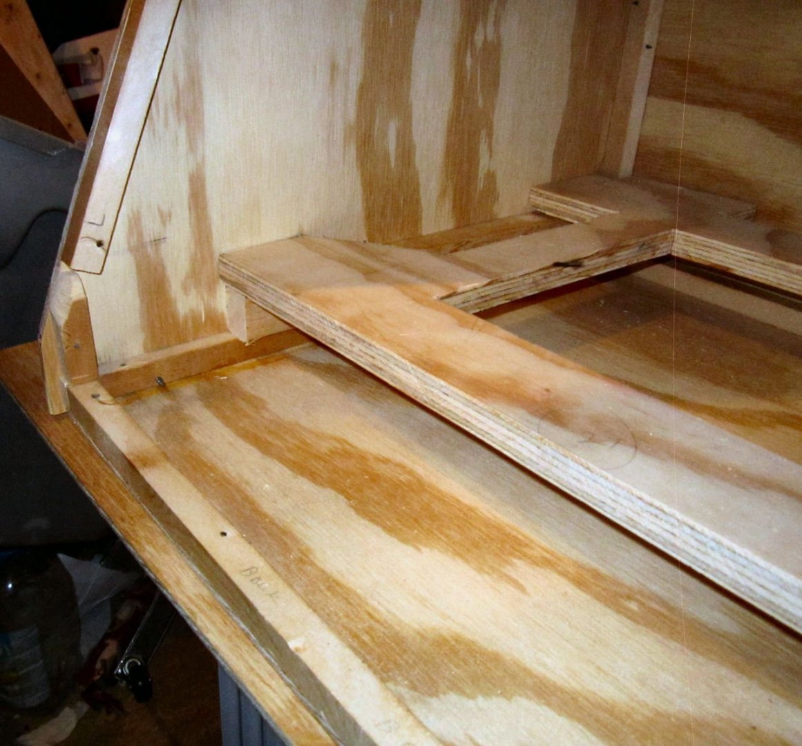
Here are pictures of the enclosure to date, from the side and front. You can see the bottom and top overhangs in the side shot. The front hinged piece is not installed yet. It rained today and I was not able to take my table saw outside to angle the upper edge, and trim it to height. I also have not decided the exact way I’m going to hinge it. I don’t want the hinges to sit below the bottom of the case, they would scratch up my workbench.
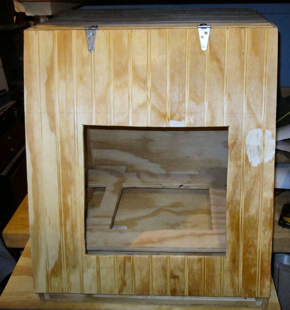
I cut the window opening in the door undersize. When I get the Plexiglas window cut, I’ll cut the final opening to match the window. You can see the desired size in the pencil marks around the cutout. With the enclosure mostly built and the router in place, I can verify the measurements for the door in the back, and cut the opening out.
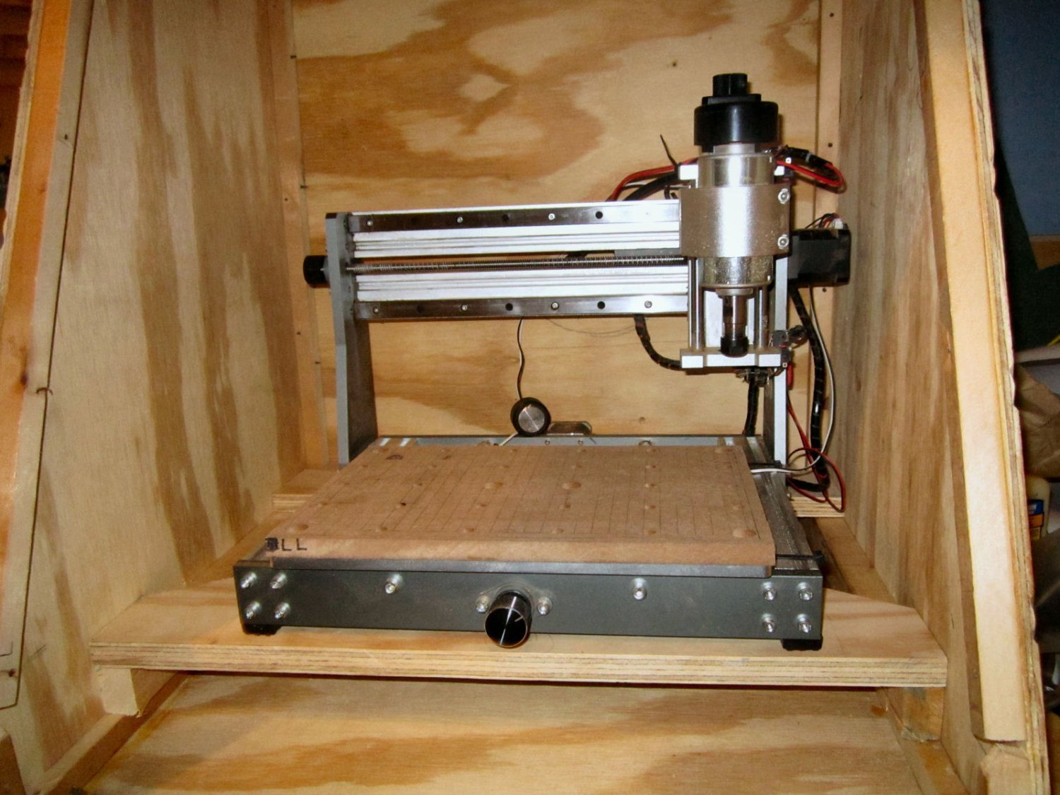
Here are two pictures of the shelf in place. Right now I have two temporary supports in place to hold the shelf, once again I need my table saw to rip 1 ½” ply strips to replace the temporary ones.
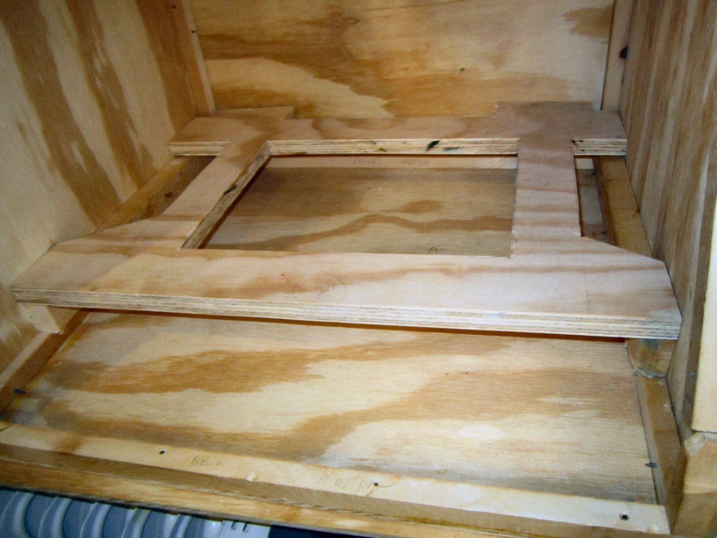
These two show the router set in place.
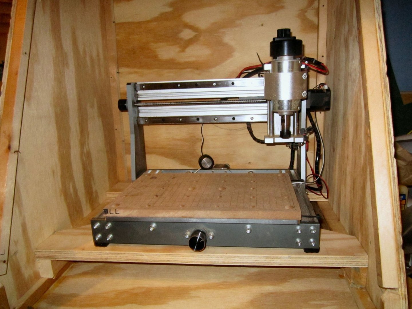

Once I get more done, I’ll write up Part 2.
- Bob Fraser, mtaylor, tmj and 1 other
-
4
-
The corn endmills are not fast ones. I use one and two flute ones mostly, for wood. As for feeds etc., my machine is stronger than yours so my feeds would not work for yours. The idea is to adjust the feeds so that you are producing chips, not saw dust. Try a faster or slower feed, to see if you get better results. Try UGS for driving the router, after you create the G-Code with Fusion. Note: that the free version of Fusion, sets all speeds to that of the cutting feeds. Fusion Pro, Easel and most of the others, use a fast traverse speed between cutting areas.
Hope this helps!
-
Part 016 Adjusting My Router – Part 2
Now that I’d adjusted the machine, I ran a test on a piece of ¼” MDF, taped and glued to the reinstalled spoil board. This was the same test board I used when I discovered the concave groves the bit was cutting before. I used the Graham Bland code, I mentioned in a previous post. The file was the one for modified machines (ones where the X-Axis limit switch had been moved, as I had done). You can find a write-up on making the spoil boards as well as the code to do it, on his Facebook page. I designed my own spoil board as I detailed earlier, but used his code for surfacing and engraving it).
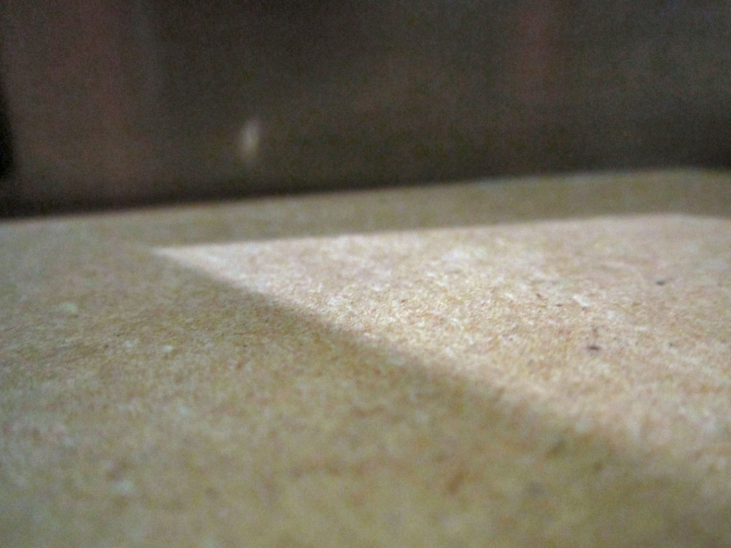
Here are photographs of the of the finished cut. The first is a close up of one corner, the second of the whole board. Nary a grove in sight!
To verify the flatness, I placed one edge of my machinist square on the surface, and shined a light behind it. No light leaked between the two, as would happen if they did not mate perfectly. The photo below shows this, though I apologize for it being a little out of focus.
Having finished verifying the improved performance, I removed the test board and ran the program on my real spoil board. The picture below shows the cut in progress. I didn’t stop the cut for the photo, the camera speed just froze the bit while it was rotating.
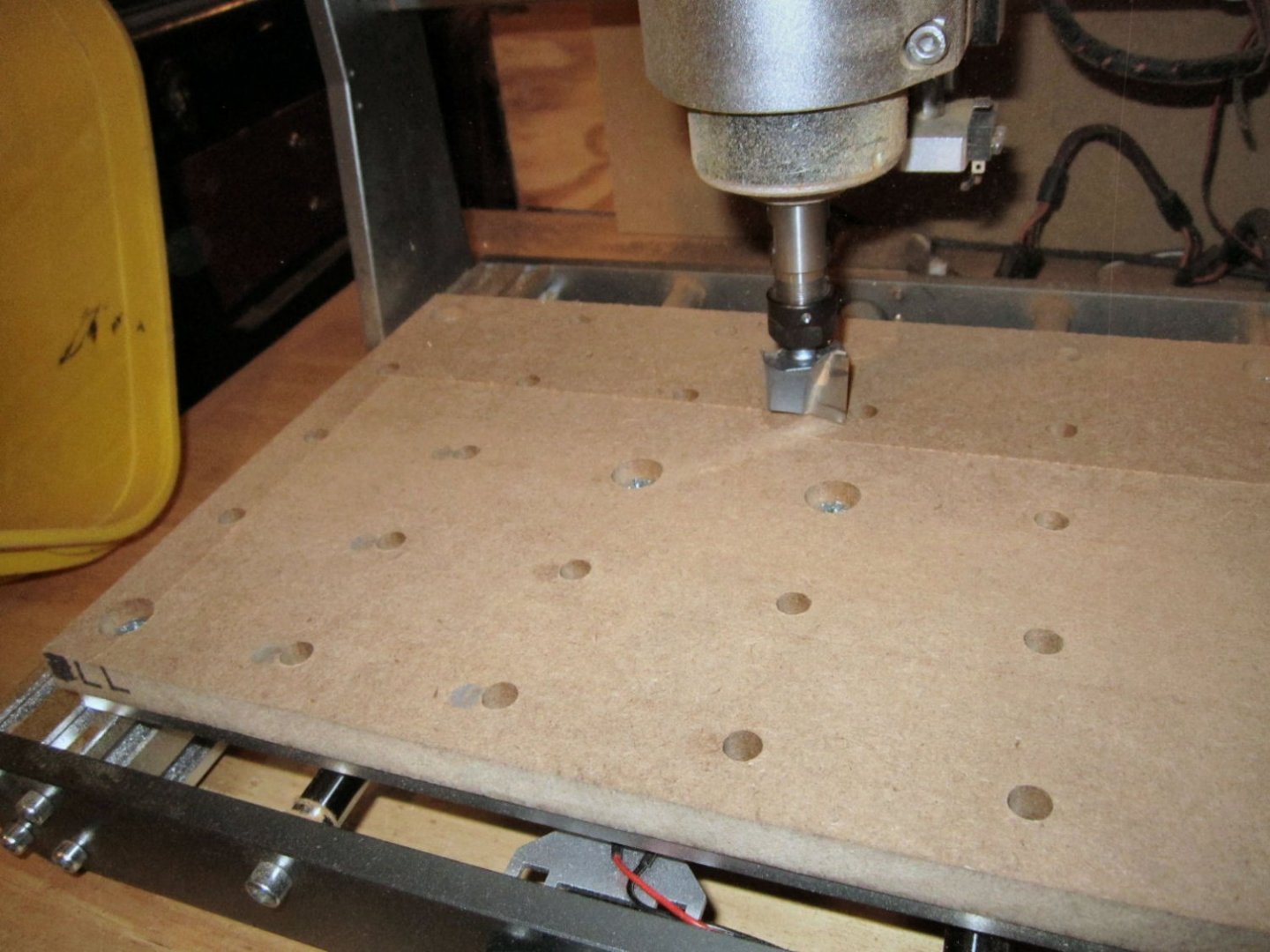
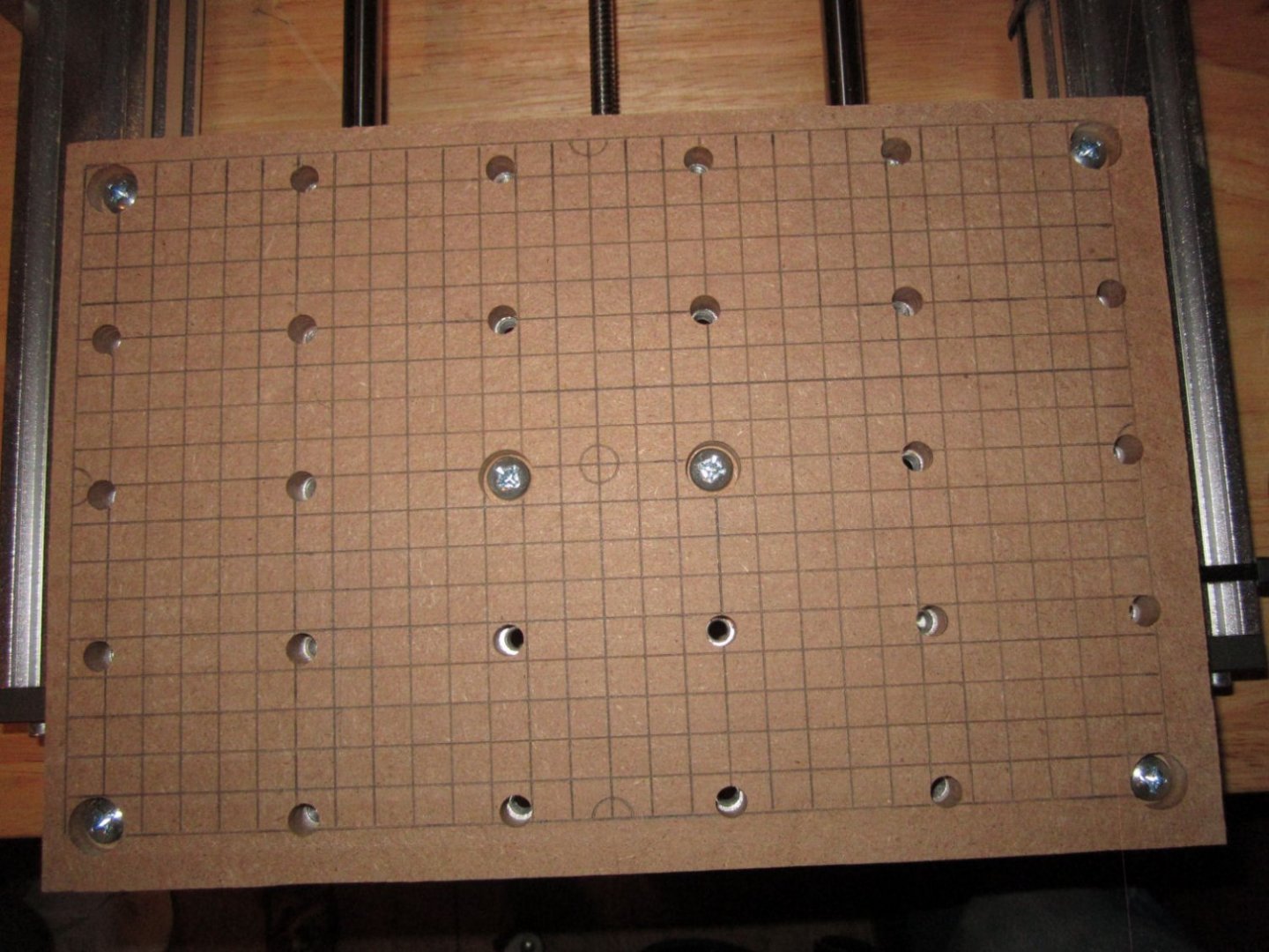
After the surfacing was done I ran his program to engrave an alignment pattern on it. His program only cuts 0.1 mm deep lines, which I found too shallow for my taste, so I ran it three times lowering the Z-Axis “0” point 0.1 mm each of the last two times.

To make the lines standout more, I ran a pencil down each line.
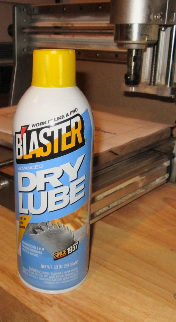
An additional note: to lubrication the slides and feed screws, I bought some Blaster Dry Lube with Teflon. This has a liquid base that evaporates after application leaving a Teflon coating that will not attract sawdust while still providing lubrication. The Teflon will build up after repeated applications, so you have to wipe the surfaces down, now and then. I also wipe up the overspray, and protect adjacent surfaces with paper masks.

- EricWilliamMarshall and tmj
-
2
-
Part 015 Adjusting My Router – Making Mistakes, So You Don’t Have To! Part 1
After trying to surface a test board, I found that the 1” bit was leaving shallow concave groves on the surface. This indicates that the spindle is not perpendicular to the surface, or as I found out later, the X-Axis and Y-Axis travel.
I assumed that the table surface was both flat and aligned to the axis travel. It was neither, but I’ll get to that later.
I want to be able to do some moderately accurate machining on this device as well as routing. The shallow groves that were left on the test board, might also affect the hold of the tape and superglue method of attaching work pieces, though they were shallow enough to not be a big factor. So I decided to go “Full Metal Machinist” on it! The “Full Metal Machinist” is a play on the title of an Anime series “Full Metal Alchemist”.
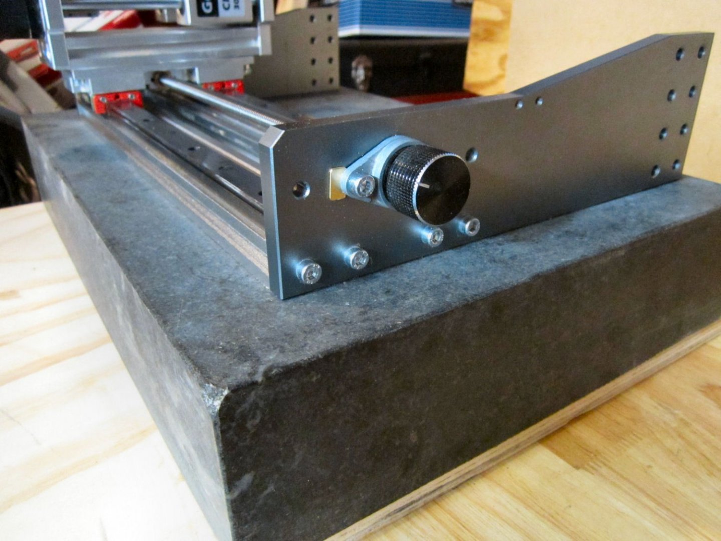
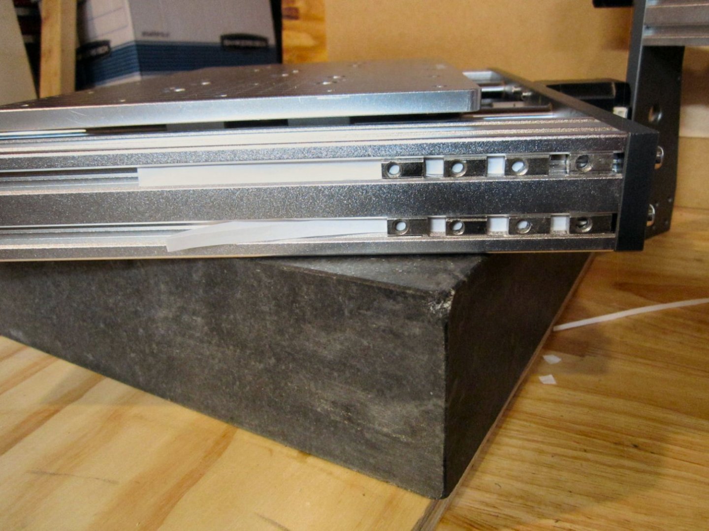
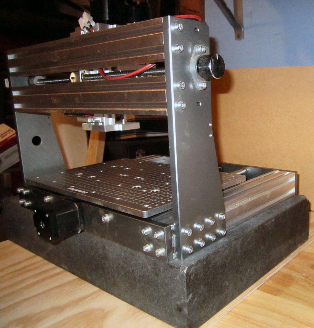
While I sold most of my large metal working machines, I still have a small metal lathe, and a good selection of measuring tools, so I decided to use those tools to improve the “Squareness” of the frame of my machine.
I have a 12” X 18” granite surface plate, that I used, but a flat piece of thick glass (well supported and used with care), or board could also be used. I bought the surface plate almost 25 years ago, and never used it, so as long as I had it, I might as well use it now. Yes, in the pictures a couple of the corners are chipped, but I can’t remember if they were so when I bought it, I do remember it was on sale.

First I removed the rubber feet and set the assembly on the plate, it did rock a bit, indicating that something was wrong. I loosened the screws attaching the uprights and pressed down on the base, a slight ping was heard on one side and the base then set squarely down on the plate. The upright on that side was not properly aligned with the base, now it was. Remembering that I had had to move one of the X-Axis travel supports when I first setup the machine, I removed the whole upper assembly and placed it on the plate, it also rocked, probably do to my change torquing it. To fix this I ran the spindle assembly to one side to keep the supports properly spaced, then loosened one support at a time, while pressing down on the upright and support to insure they were flat to the plate, then I tightened the screws. Moving the assembly to the other side, I repeated the process.
Now it too laid down flat, insuring it was in line also. I used my machinist square to check the squareness of the uprights to the traveler supports, and they were good.
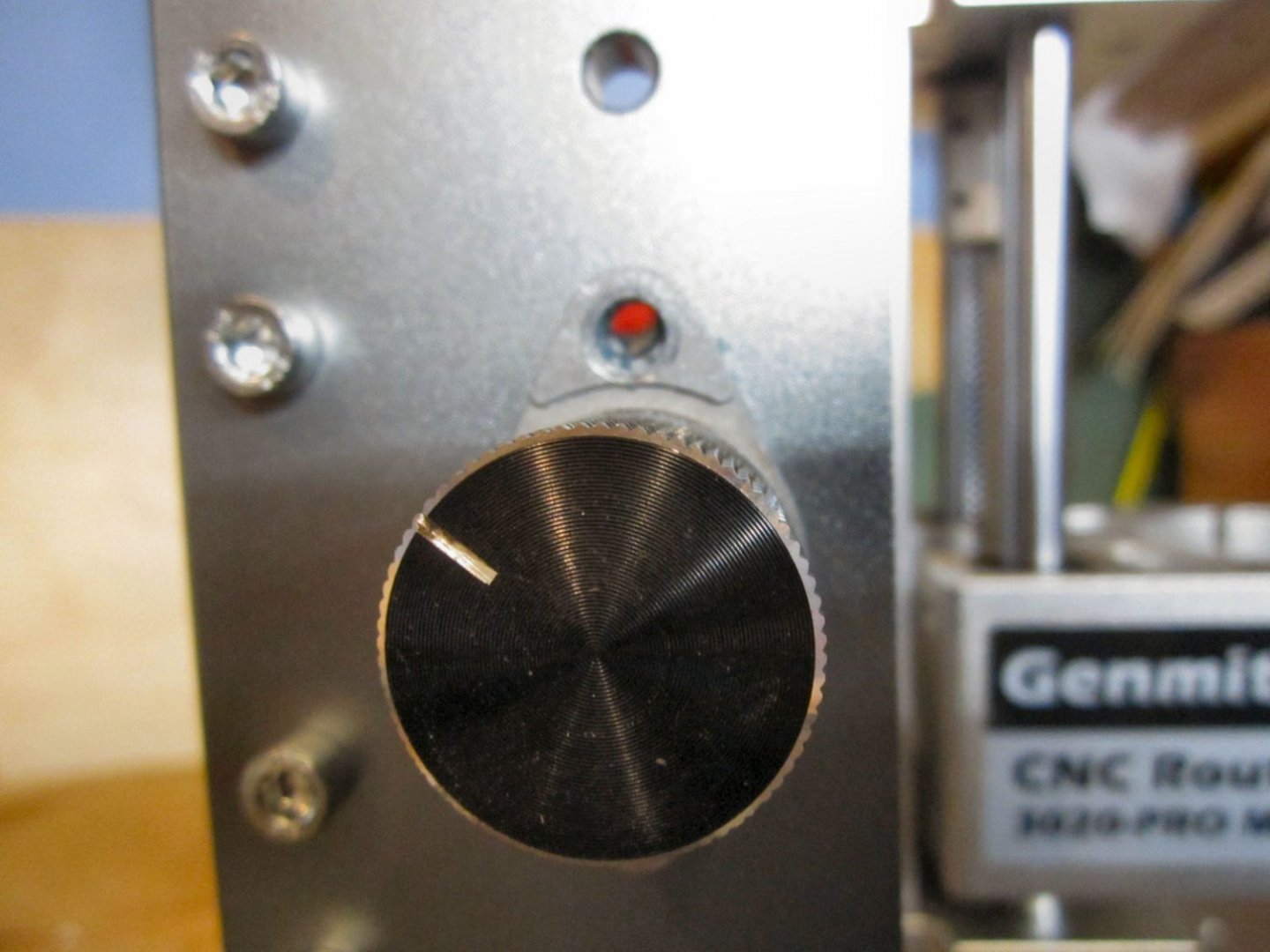
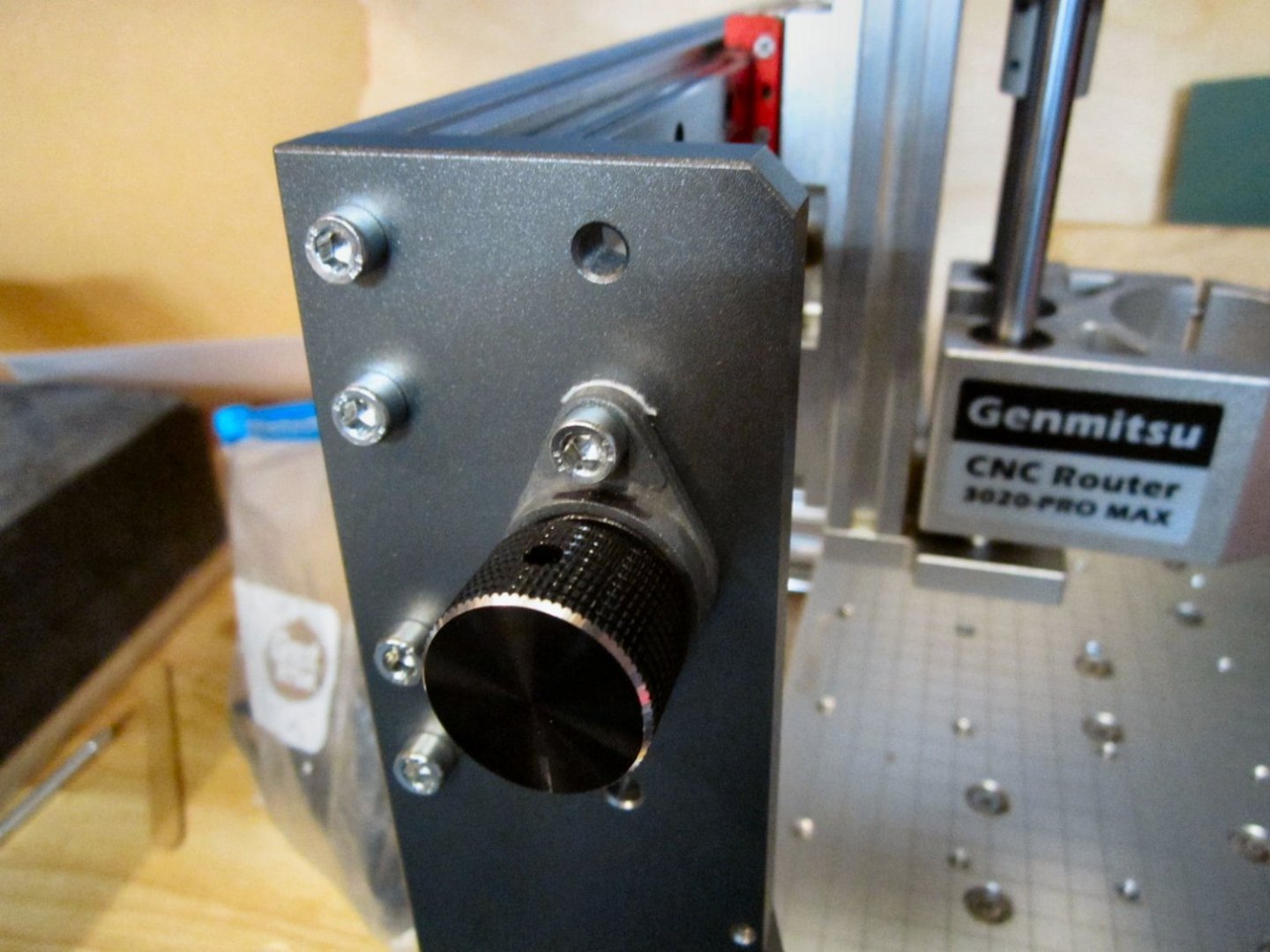
Ignore the small wedge in the photo below on the X-Axis knob assembly, that will be explained later. I forgot to take this picture the first time, so this photo is from further along in the process.
I reassembled the router while it was again on the plate to insure the uprights and the base were aligned.
I mentioned at the beginning that the “T” Nuts supplied with the machine had a spring loaded ball that was supposed to hold the nut in place while you attached the upper assembly, but that many of them still moved or fell out while trying to assemble the parts, the first time. This time around, I cut narrow strips of cardstock and found two layers inserted in the groves held most of them firmly in place. Two still gave me trouble, but that was better than several, and three strips was too thick for the rest of them.
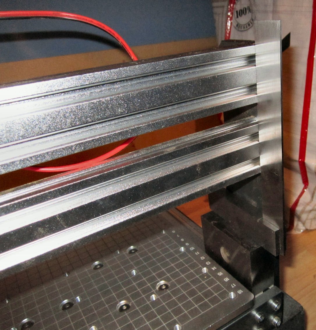
Using a 123 block and my square the alignment looked good. The block is sitting only on the frame side rail, there is a slight lip where the back frame piece and it meet.

Before I took the machine apart I was having problems with the X-Axis binding at the end with the knob, another reason I went through all this. After I had it reassembled, I ran the spindle assembly back and forth with the knob, and it was still definitely binding at that end! I removed the mounting screws for the knob bearing and the binding disappeared, so there was something wrong with the mount. I ran the spindle all the way up against the upright and looked at the position of the mount, in relation to the screw holes. If the lower screw was installed finger tight, everything was OK, but the upper mount screw hole did not aligned with its hole on the upright. I drilled that hole out a little and installed the screw, but binding still occurred. I looked at it more closely and with the upper screw loosened, I saw a slight gap between the mount and the upright. A cardstock shim took care of the problem (see the photo two pictures above this one). I moved the spindle assembly back to the servo end, and loosened the X-Axis servo mounting screws and shifted it a little to get that end of the feed screw to slide freely into the coupler. This eliminated the binding.
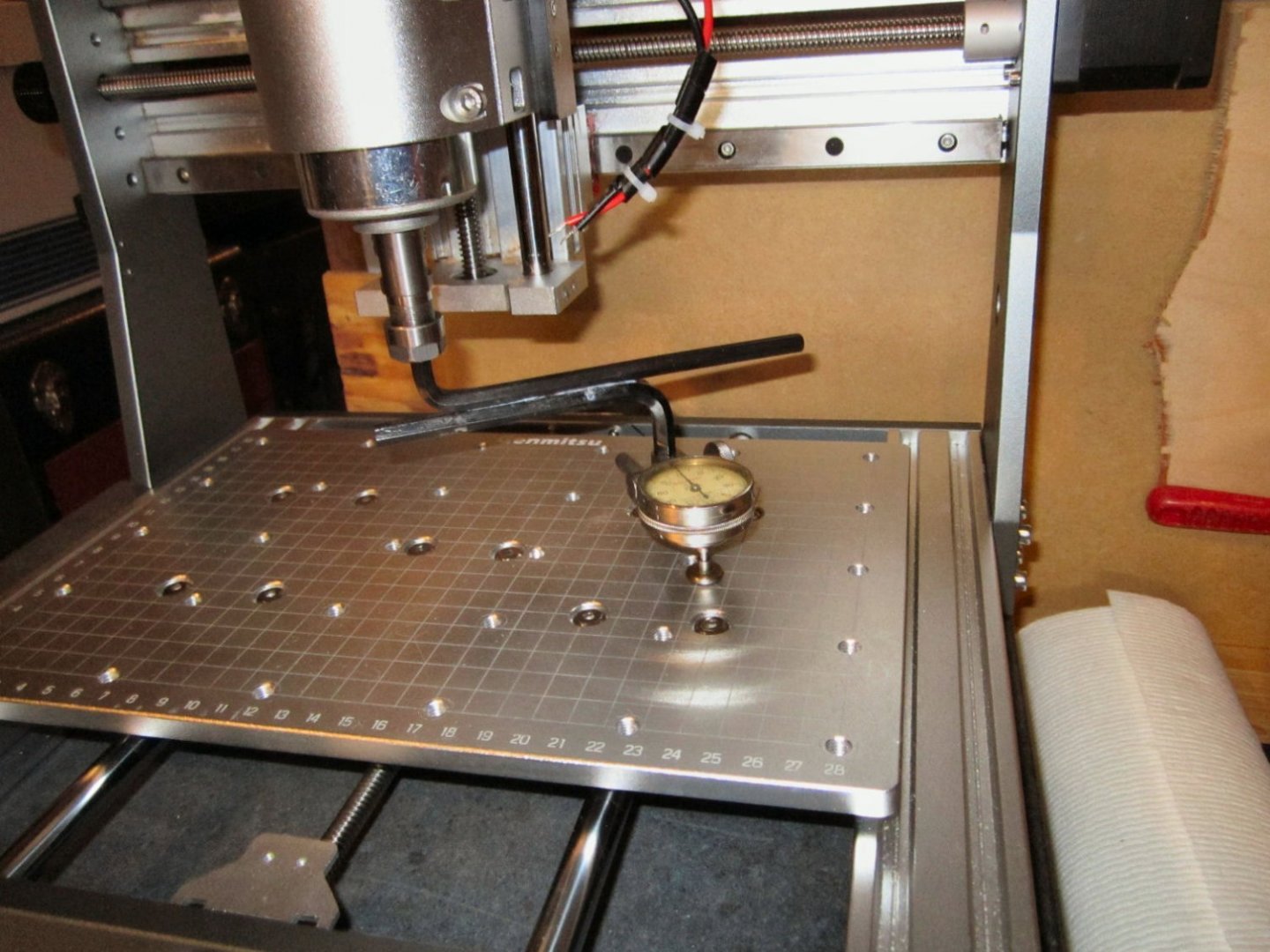
With a milling machine, one of the first things you do is level the head of the machine. For most of the milling machines we would use, the head/spindle is fixed in relation to the Y-Axis, but can be tilted left or right in relation to the X-Axis. This allows you the drill holes or mill a side at an angle. For normal milling you need to insure that the head is perpendicular to the table surface. You do this with a Z shaped holder and a Dial Gauge. So I made a setup for my spindle to do this.
I took a ¼” Allen Wrench and a 7mm Allen wrench and super glued them as shown in the picture below. I bought Sainsmart’s 15 piece collets set when I bought the router, as I knew I would at least need the ¼” collet, and I got a discount on it when I bought it with a cutter set. I’m glad I did as the largest collet was a 7mm, which fit the ¼” Allen wrench, (remember the flats on the wrench are ¼” apart the tips fit the 7mm collet). The tips of the 7mm wrench fit the 3/8” clamp on my dial gauge. I positioned the spindle at the center of the table, X and Y, and set the position of the dial gauge midway between the Y-Axis table edge and the first etched guide line closest to it (95mm from Center). I used cheap Allen Wrenches, and will keep this setup for future use.
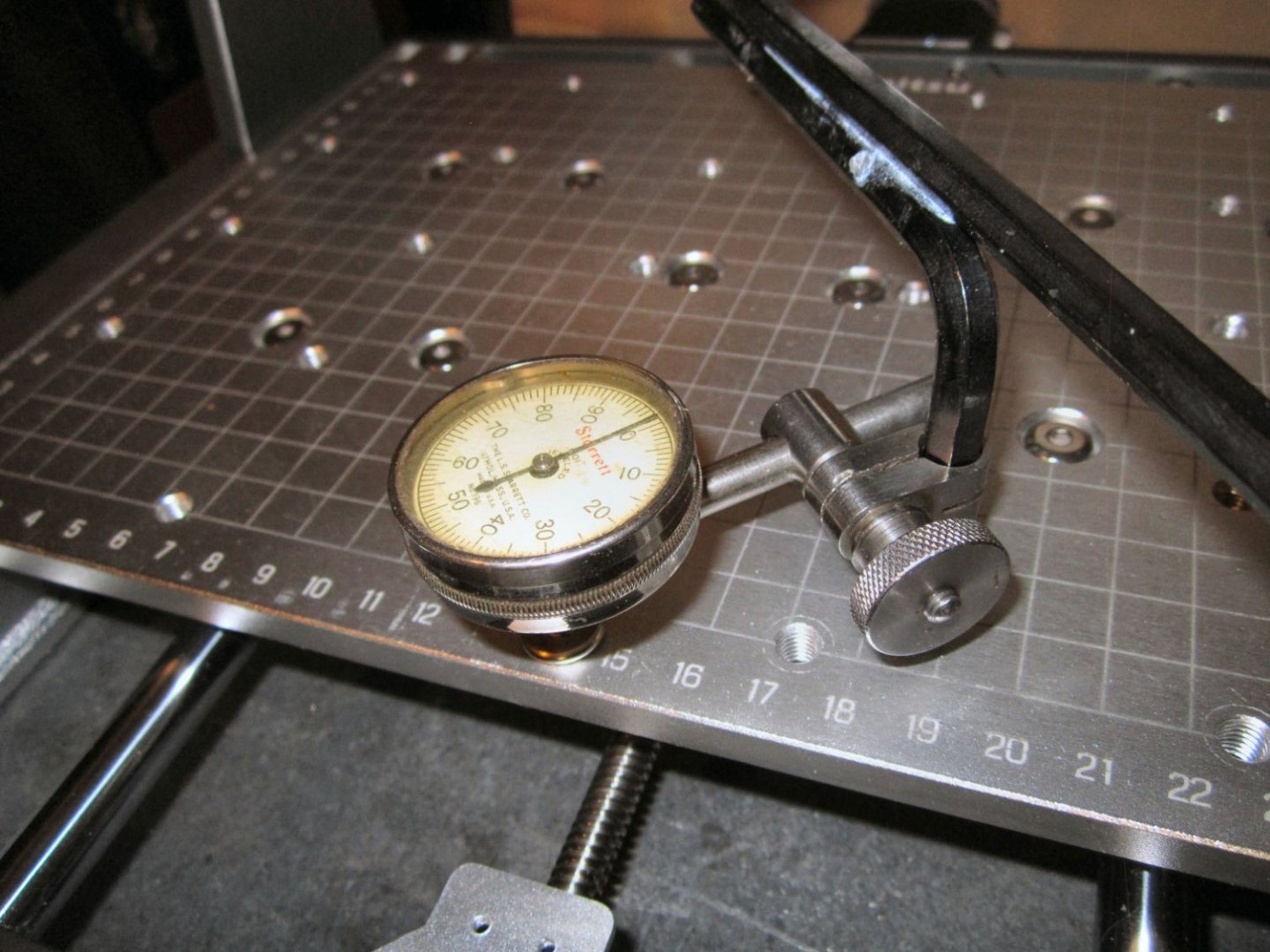
Using this setup the Y-Axis measured 0.050” higher at the front than the matching position at the back, and the X-Axis measured 0.057” higher at the left side of the table!
As this did not make sense if the table is both flat and aligned with the Y-Axis slide rods, I measured the table in relation to the front and back base frame pieces, as well as the side ones. Here is a drawing of the results.
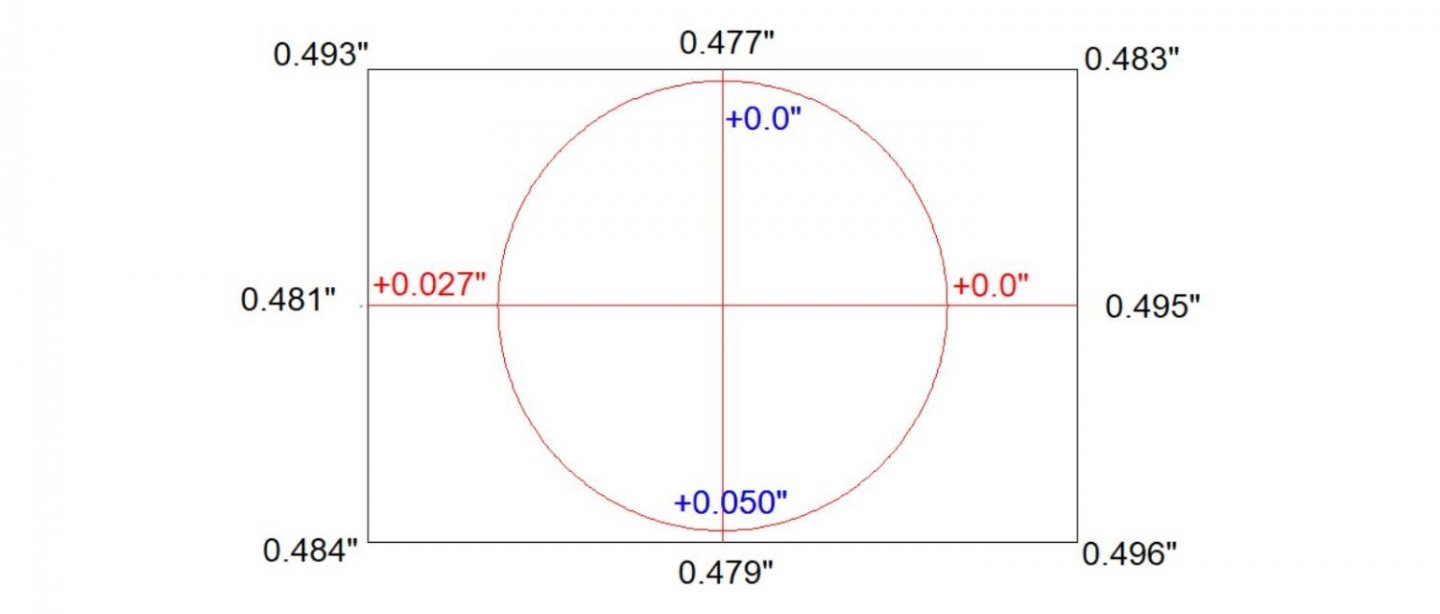
As you can see the table casting is warped along a line from the upper right corner to the lower left corner, sort of like a slice of bread held at opposing corners when held in the air. The warp is about 0.010”. The Y-Axis table heights are much better, only 0.002” difference. The X-Axis is not as good. The left side is 0.014” lower than the right.
Because the table is level in the Y-Axis direction, the Y-Axis error can be corrected by tilting the whole upper assembly (forward in this case), I did not worry about it now. The X-Axis is a whole other problem!
There are four ways to fix the X-Axis:
1. Ignore it. If, you are doing small pieces it may not make enough difference to bother making mods to your machine, but if you are doing larger ones this will cause a lot of carving to get even depth cuts.
2. Use a thick cutting board, and mill the top surface down a little more than 0.050”(~ 1 mm). This still leaves the problem that started this, the shallow groves.
3. Raise or lower one of the uprights to make the X-Axis travelers match the angle of the table.
4. Shim the table. This means you have to make custom shims for each linear bearing holding the table, a tedious endeavor, and means you need shim stock to start with.
I chose to go with the third option.
Here is where I made my first mistake. I was going with getting the spindle perpendicular to the table, which I was able to do with much work. Then I measured the height of the spindle to the table, and discovered that the X-Axis travel was over 1 mm higher on one side of the table than the other! Not good for any type of work, the X-Axis travel should always be parallel to the table! I will skip all that I went through doing it the wrong way, and go to how I finally did the adjustments.
Initially the left-hand measurement was 0.057”, but I was able to get it down to the 0.027” by loosening the mounting screws between the spindle travel assembly and the plate that mounts it to the X-Axis traveler linear bearings. This was all the adjustment the screw holes allowed. I did totally remove the spindle traveler, to see if I could enlarge the holes to allow more adjustment. Don’t do this!! I discovered that the assembly is held in place with four “T” nuts, all of which promptly slid all the way to the bottom of the channels in the extrusion which makes up the base. In the end there was not enough material to allow me to enlarge the holes, anyway. I ended up having to removed the spindle traveler bottom plate so that I could slide the “T” nuts (loosely screwed into the bolts) into the channels as I slid the rest of the assembly down over them. So 0.027” is the best I could do to correct this, and as it turned out, that was enough, in the end.
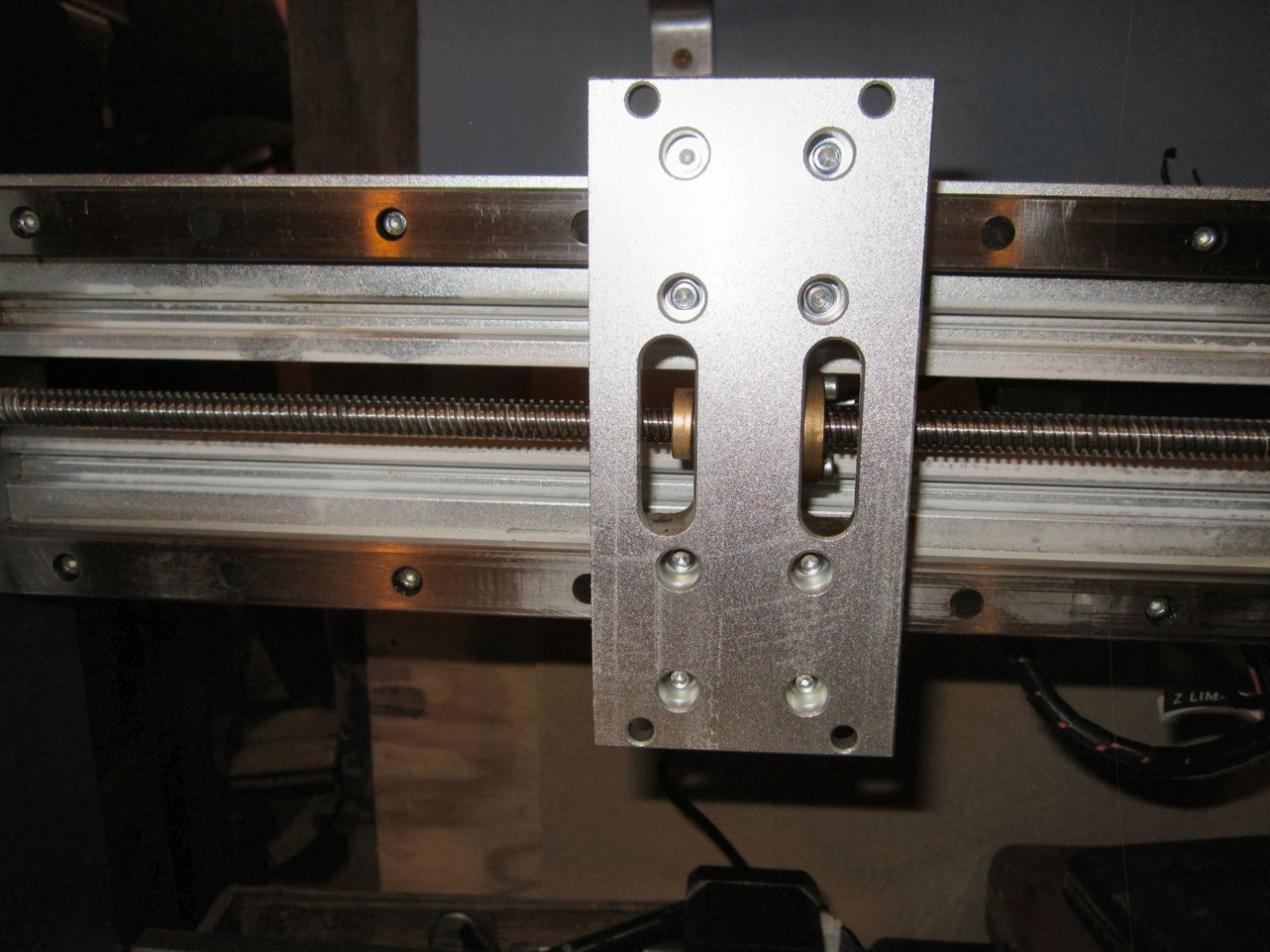
The spindle traveler removed from the machine, showing the “T” nuts.

This picture shows the plate that attaches to the linear bearings. The plate is riveted to the bearings, not screwed, so no adjustment possible here!

While from this side it looks like I could slot the screw holes horizontally, there is no meat to enlarge the holes vertically, and the other side has clearance holes machined for the screw heads with quite close tolerances, So way too much would have to be removed to make any further travel possible. Also there is too much risk of cutting up or down through the thin amount of material along the top and bottom edges, if I tried.
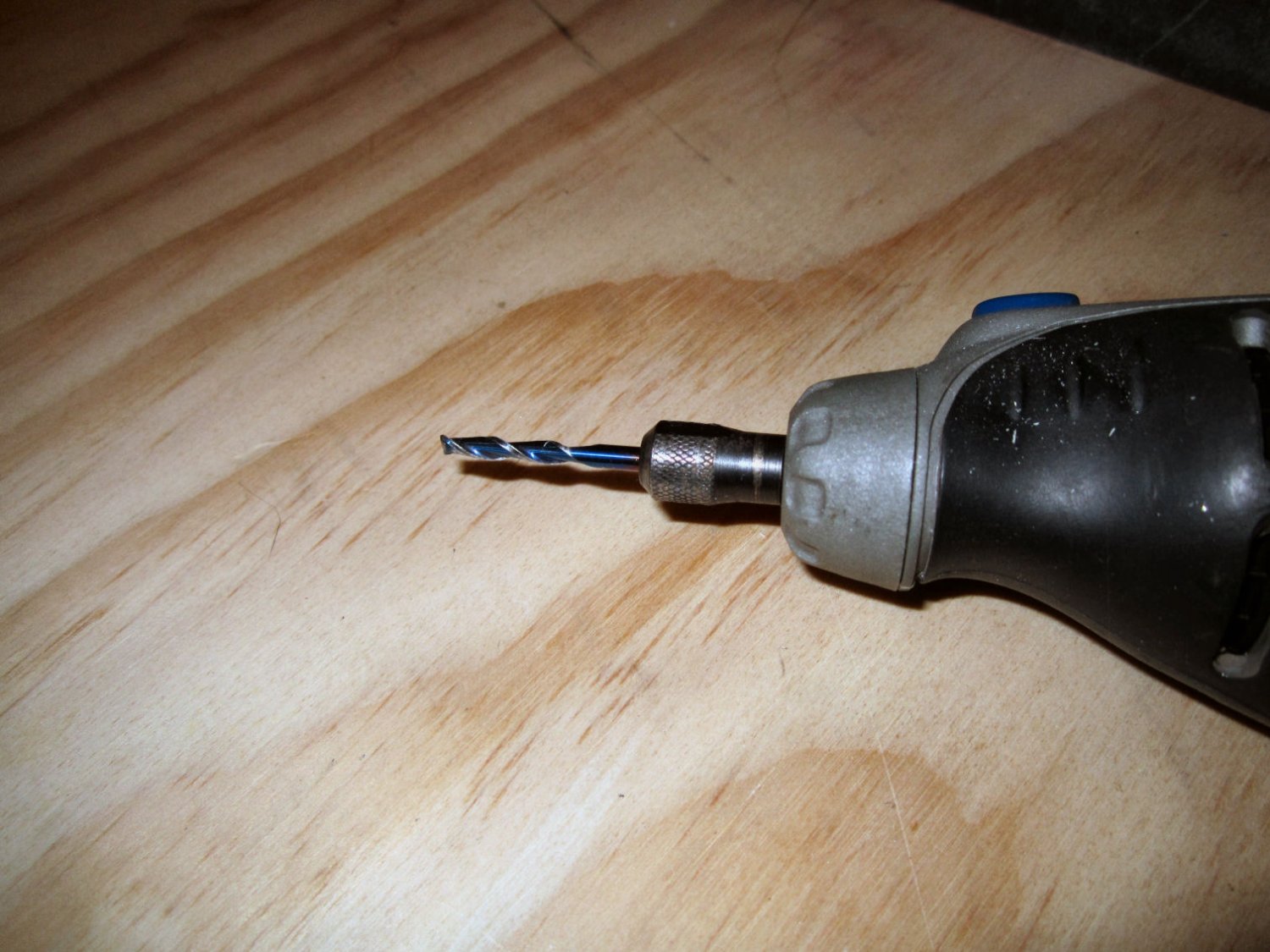
So the only adjustments left are making the table parallel to the X-Axis traveler and rotating the whole assembly forward or backward the align the spindle traveler/ spindle shaft to be perpendicular to the table surface. The X-Axis error I got out by lowering one upright and raising the other. Unfortunately, the mounting holes in the uprights did not have enough clearance to allow me to do this, fully. I chucked one of the 1/8” bits I bought for the router in my Dremel, and slotted the hole vertically to give me the clearance I needed. I used slight pressure so as not to break the bit. I got it done this way, but the bit was chewed up enough I will not use it for cutting on the machine.

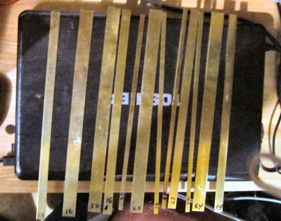
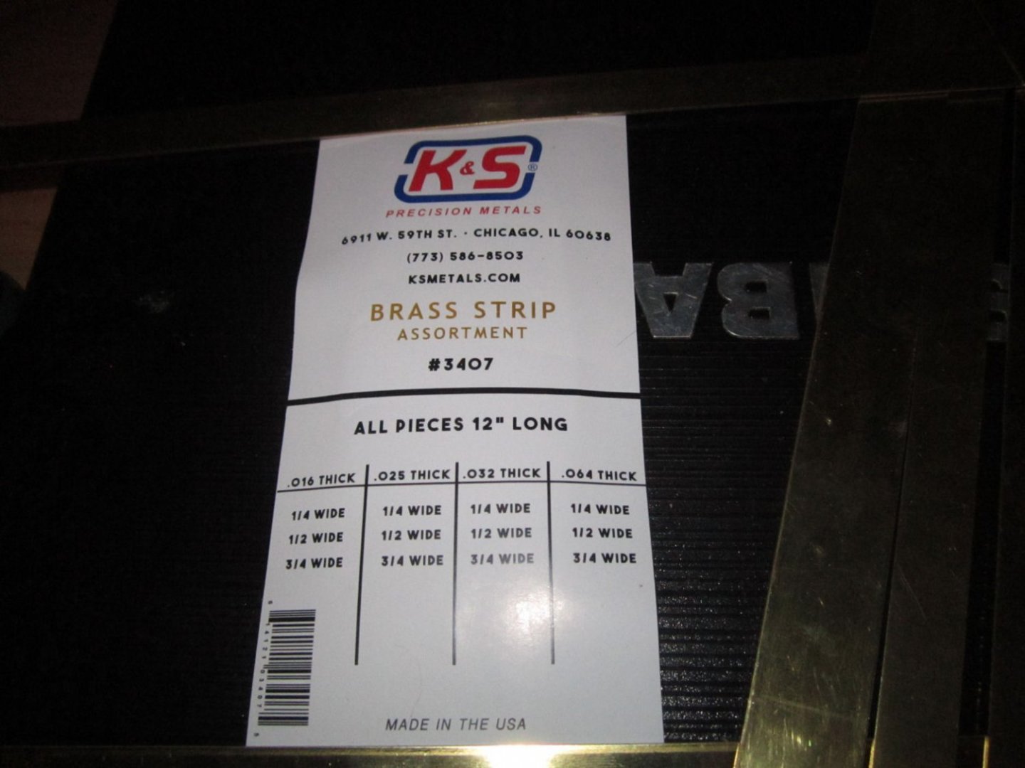
To help with adjusting the height of the uprights I used some various thickness brass strips I got from K&S. I put one under an upright to raise it, or under the base extrusion to lower it. I loosened all the screws and only tightened the bottom back screw to hold the upright, in place, measured the result, I then went to the other side and adjusted that. After a few tries the situation vastly improved. I was able to get the X-Axis to within 0.12 mm (0.004”) of parallel side to side.
Leaving the strips in place I then slightly loosed the two back screws and rotated the whole assembly (forward in this case), to get Z-axis perpendicular front to back. I also got this within 0.004”. Not perfect, but I think within very reasonable alignment!
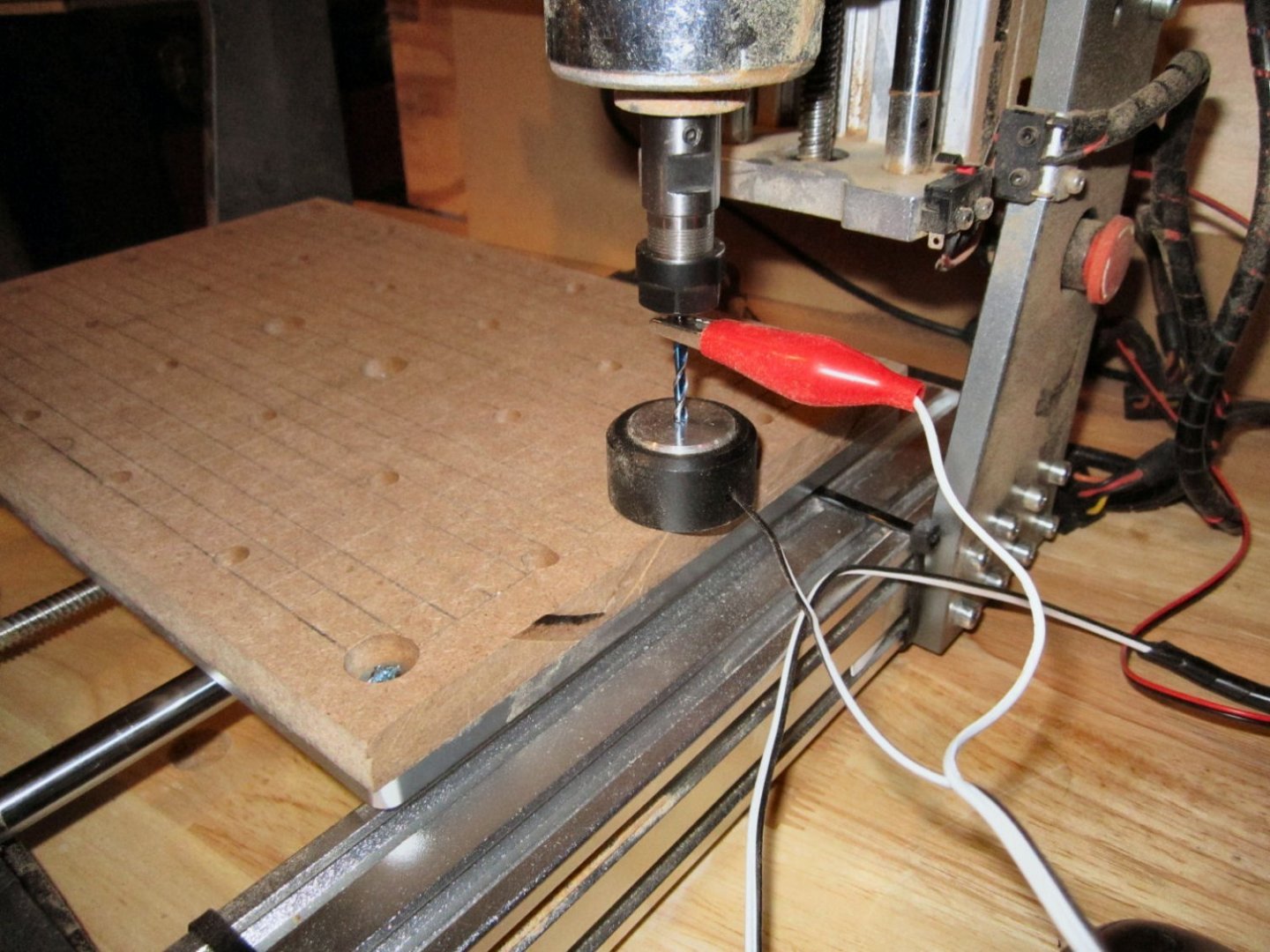
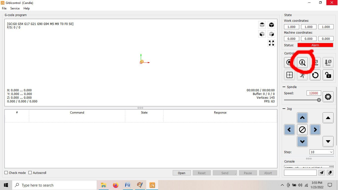
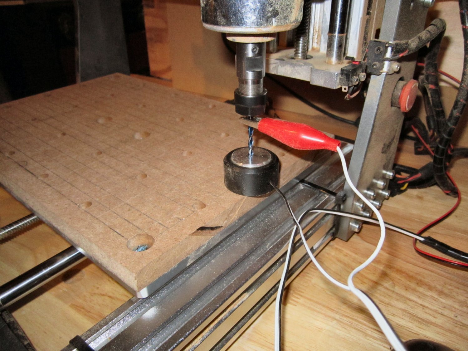
To measure the side to side alignment I used the machine itself. I placed that much abused 1/8” bit in the spindle and used the Z-Probe that comes with the tool and the Z-Probe function in the Grblcontrol program to measure the relative height at each side of the table. I moved the table to 0,100 mm (middle of the right side). Zeroed the Z-Axis height, then moved the spindle to the left 290 mm (291 mm is the maximum X-Axis travel), and used the probe function to find the height at that end. As I was looking to get both sides the same, I didn’t need absolute height, just the difference between the two sides.
The picture below shows the Z-Probe in use, at a later time.
To get the spindle perpendicular to the table, I used the dial indicator. You can’t use the machine, as the table travels under it, the spindle doe not travel across it. From my previous measurements, I knew that the table was already level with the Y-Axis slides. (in the middle, at least).
After that I tightened all the mounting screws, and rechecked that setup
The next Part will show the results of all this work.
-
Welcome aboard, and thank you for your service!
- EODGoat, Keith Black and mtaylor
-
3
-
Part 14
I redesigned the cabinet for the router. The first design had a notch cut out of the bottom front to allow a little more head room, for my head. The machine will be on a shelf over my work bench, and I was allowing a little more room to prevent banging my head getting up and down.
The “temporary” shelf I put up is 24” wide though, and I have not been having any trouble with hitting it so I changed it so the bottom corner is square, greatly simplifying the cutting and construction. This , of course means that once built I’ll be banging into it all the time! LOL!
Here is a graphic of the cabinet design.

I designed it so that the sides overlap the top, back and bottom, hiding those seams, and the door and front overlap the sides. I’ve left the top, bottom, and front overly long. I’m going to assemble them with the excess hanging past the final edge, and then trim them flush with my hand router, once the cabinet is assembled. This gives me “wiggle room” for cutting mistakes. The door will also be over long, and I will mark it once installed and cut the overhang off with a saw. I also plan to cut out the two sides slightly over size, then screw them together and finish cut them as a unit, to insure they match.
The graphic below shows the parts assembled, before trimming (The overhangs are exaggerated).
-
Welcome aboard!
- Keith Black and mtaylor
-
2
-
Well, I finally got the routine for skimming the top surface of the spoil board to work. Unfortunately, the bit left slight groves on the surface, which means my machine is slightly out of true! I don't know if I assembled it wrong, or when I took the spindle assembly apart I got it back together out of square. I'm going to have to get my surface plate out, and go "Full Metal Machinist" on it.


3d printing process
in 3D-Printing and Laser-Cutting.
Posted
Got my AnyCubic 4K Mono two days ago, and bought some Elegoo resin. Have to build an enclosure for it before I can do anything with it though. My shop is not well ventilated.