


thibaultron
-
Posts
2,878 -
Joined
-
Last visited
Content Type
Profiles
Forums
Gallery
Events
Posts posted by thibaultron
-
-
As to the accuracy of the boat. He pulled the design from a reputable source, and apairently the Santa Maria replica has one.
-
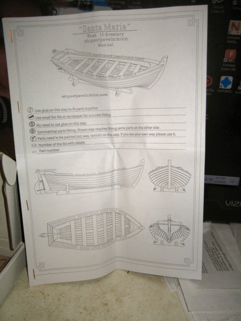
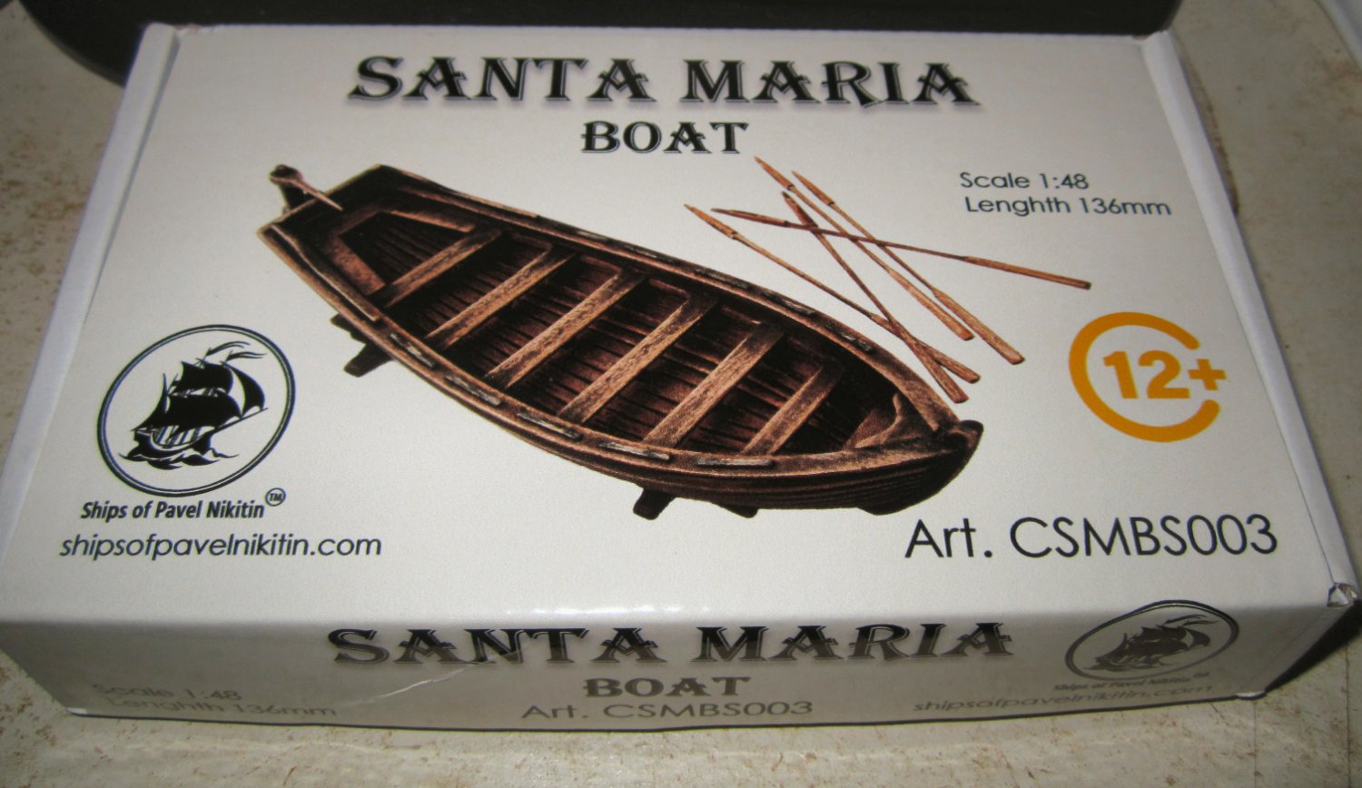
Pavel Nikitin (https://shipsofpavelnikitin.com/shop) is a ship kit manufacturer in the Ukraine that makes a series of well designed laser cut wooden ship and small boat kits. This kit is a 1/48th scale (136mm length) model of, I believe, a ship's boat from the Santa Maria from plans by H. E. Adametz. The kit costs ~$20 US, He also produces a larger 1/24th scale (272 mm Length) kit with mast and sail “The “Santa Maria” Caravel Boat” for ~$66 US that looks to be the same boat as this smaller kit, sans the mast and sail.
The kit comes in a small box about 6 inches long.

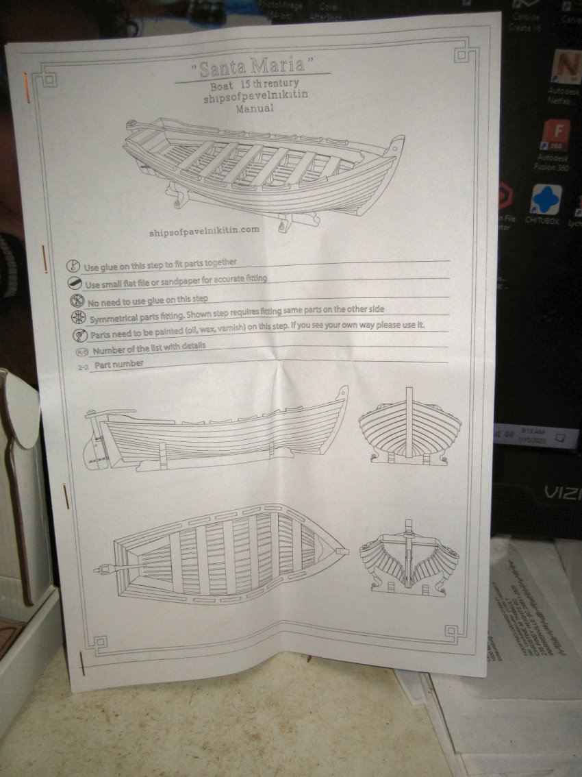
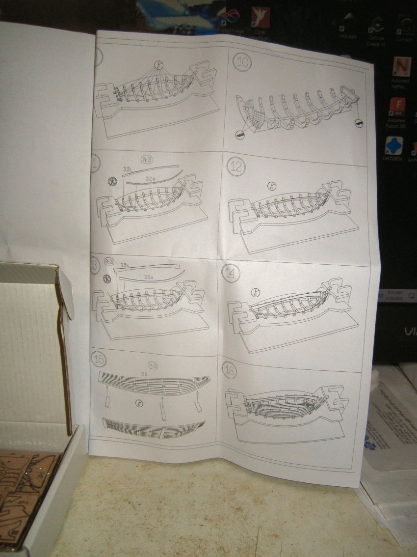
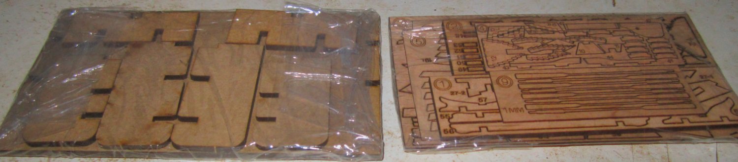
Opening the box there are a four page set of plans/pictorial instructions, and two plastic wrapped packages of laser cut wood parts.
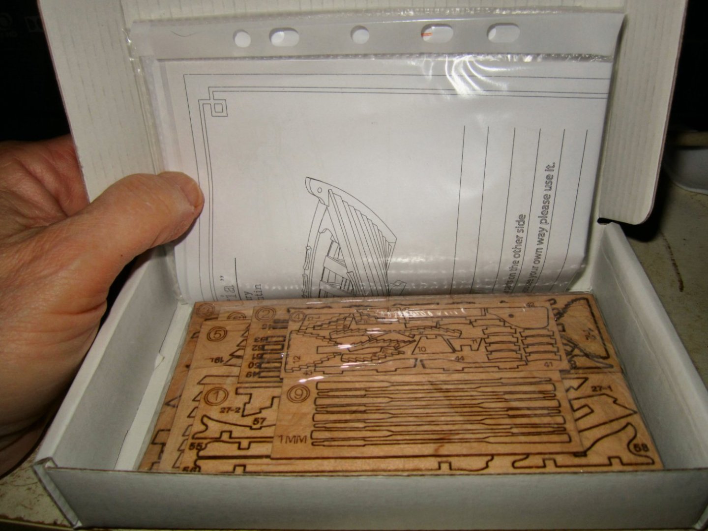
The instruction sheets have pictorial type instructions similar to a plastic kit. There are no written directions, so some modicum of wooden ship model knowledge is needed. Perusal of a few build logs on this forum, would provide the needed knowledge.
Here are pictures of the cover sheet and a sample page of the instructions.

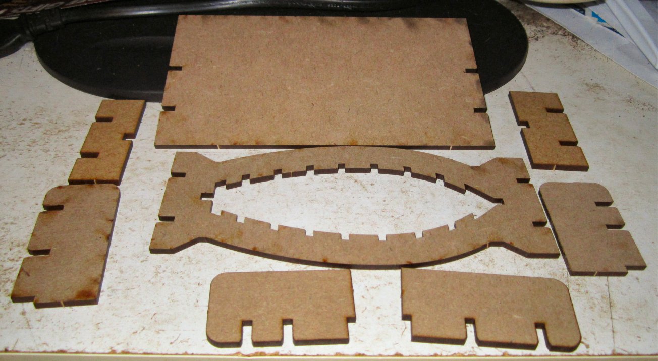
The kit is built upright, in a cradle, the parts for which come in one of the wooden packages.
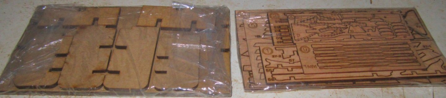
Opening the bundle of the parts for the boat itself reveals 7 sheets of laser cut parts. Sheets 1 through 6 and sheet 9. I’m assuming the sheets 7 and 8 are the cradle parts, thought these are all separate parts, not two sheets of parts.
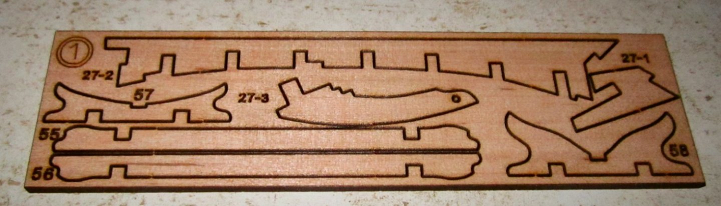
Sheet 1 has the keel, stem, stern post and display cradle parts.
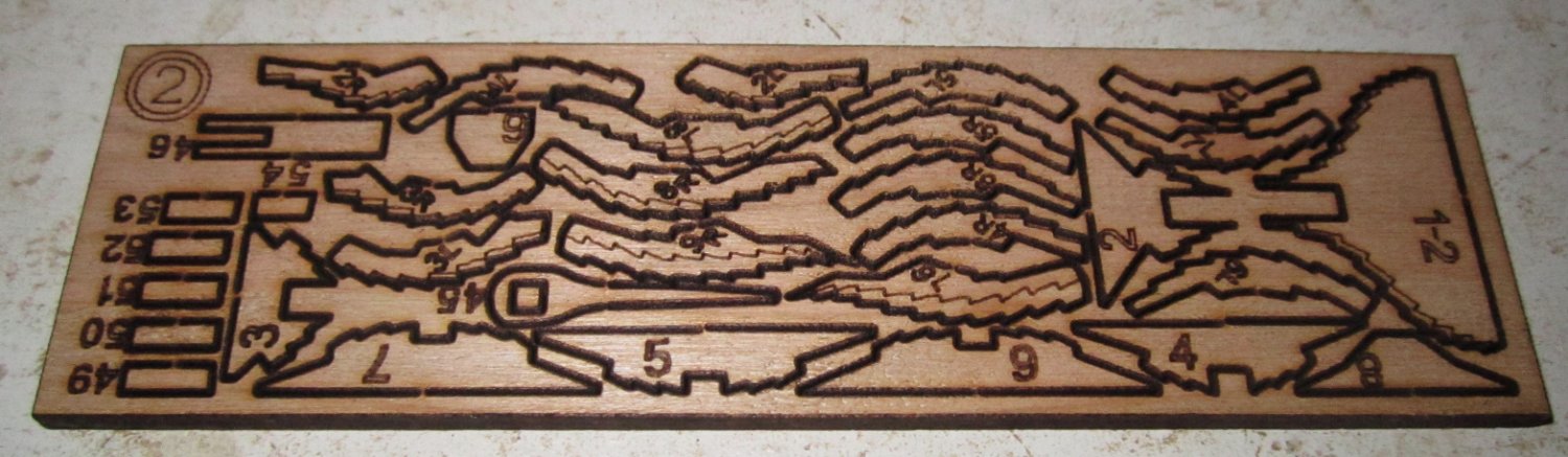
Sheet 2 has the frames, stern, and some smaller parts. The frames have secondary lines for beveling the frames before installation for the initial fairing of the hull.

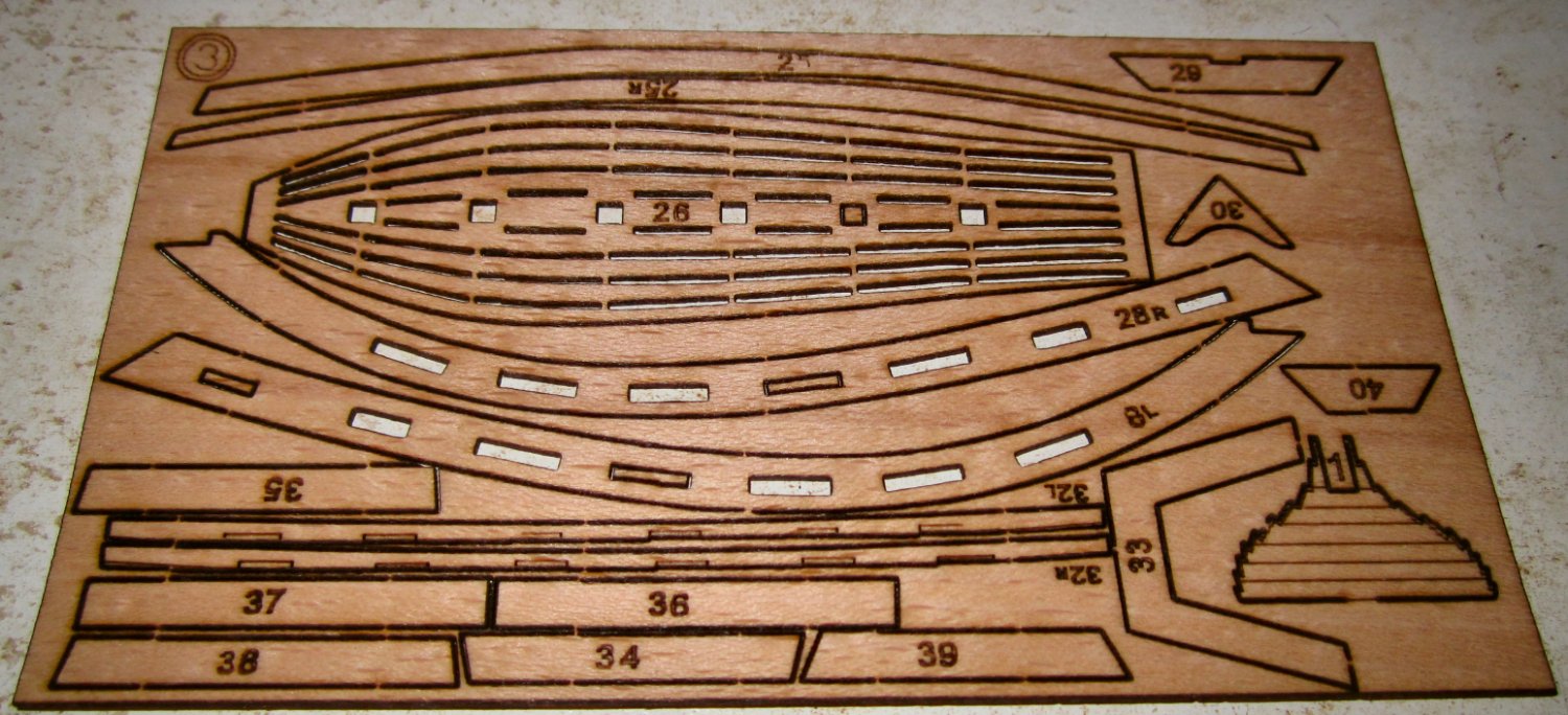
Sheet 3 has the engraved planking for the final stern layer, the gunnels, seats, and floor.

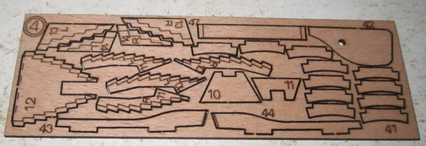
Sheet 4 has more frames, small parts, and the rudder.
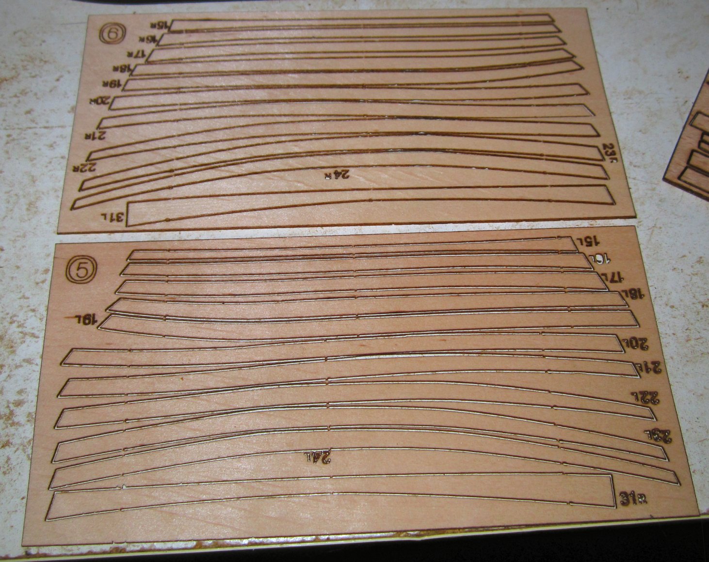
Sheets 5 and 6 contain the pre-cut planking.
Sheets 7 and 8 are the parts for the construction cradle.
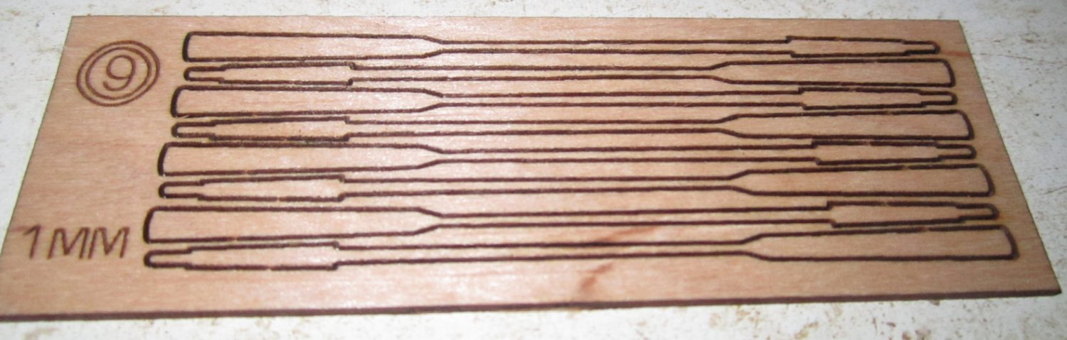
Finally Sheet 9 has the oar blanks.

The kit has no metal parts, but other than perhaps rudder pintles, which can be made from paper, you really don’t need any for this small model.
This kit should build a nice display piece for a small space.
- Knocklouder, Pitan, Ryland Craze and 2 others
-
 5
5
-
-
As an added note, one of the survivors was the Bismarck's ship cat, who the crew kept, and named Unsinkable Sam. When the cruiser was later torpedoed and sunk, the cat again survived. He then was put on another ship, which was also sunk, and survived again. After that he was sent to an old folks home, where he lived out the rest of his life comforting the patients.
-
-
For the char, you can scrape it off with a blade held perpendicular to the surface. Its faster and removes less material.
- Dave B, JerryC, Chuck Seiler and 1 other
-
4
-
Leave the parts clamped for several days, so that they completely dry in the clamped position. I know that you want to get right back to the model, but you will waste much more time fighting the warps later. For scribing the deck, I use the tip of a razor saw drawn along a straight edge to grove the lines. Be careful to pull the tip so the grain of the wood pulls the tip into the straight edge. If it wanders out of line stop and run your finger nail over the mistake to flatten the wood back down. When done run a pencil along each line, erase any mistakes. Then sand lightly. A clear finish will seal everything (varnish, or even thin CA spread with a bit of cardstock). On my RC Warships, the Ca coating has held up over 30 years. Do the scribing before installing the deck.
-
-
-
-
Soak the hull in IPA for a while, this generally will soften and remove most paints.
- Canute and king derelict
-
2
-
Might I suggest, if the trusses are going to line up with the vertical studs, widening the bottom of the truss and running it down 3" or so and screwing it ti the stud. You could also run a straight strap across the side of the stud, and the side of the truss, instead of screwing through the edge of the plywood. This would solidly tie them together, and lock them from allowing the base to spread. Not being famillar with UK weather, I don't know if you have to deal with snow loads or not.
-
For the intermediate trusses, are you going to build actual trusses, or just place rafters? If just individual rafters, it would be much quicker to just measure and cut them in place. Cut a board a little long, drop it in place above the wall and center ridge beam, then run lines onto the board with a straight edge. This will also take into account any warpage in the walls. This should take a fraction of the time to design the rafters.
-
Try Vallejo or Tamiya acrylic paints. The tube stuff is craft paint, with a much larger "grain" size than the true model paints. With acrylics you need to prime the plastic, before the color coats go on. You also need to wash the pieces in soapy water, rinse, and then use gloves until the painting is complete. The oils from your fingers can cause adhesion problems with the water based paints. Vallejo sells two types of paint, Model Color (for brush painting) and Model Air (for airbrushing). The Model Air is already thinned for airbrushing, though you still may have to add thinner. It depends on temperature, humidity, and airbrush type and air pressure. Acrylics dry much faster then the old style enamels, so you have to work a little faster with the airbrush. YouTube has many airbrushing videos, that can help you if you want to use one.
Vallejo's Primers don't sand well. I use Stynylrez primers from Badger. Their Red Brown is perfect as the red anti-foul paint color, without having to use an additional color coat. Note that I bought both the Model Color and Model Air Hull Reds, before I found the Stynylrez primers, and they are a slightly different shade of red. I bought them several years ago, so they may have corrected this. The Stynylrez primers are made for styrene, vinyl, and resin, I don't know how well they work on metals. For wood, no primer is needed.
Here are a couple of links that are helpful:
The Barbatos Rex YouTube Channel
And an Interview with the Owner of Badger Airbrush Company, which is very informative. Note that in this video, he says that all the manufactures buy their airbrush compressors from the same factories in China, and that, unless you want the Brand Name Tag, buy the cheaper Chinese brands.
- king derelict and Canute
-
2
-
-
-
-
-
Welcome!
- Keith Black, Dave_E and mtaylor
-
3
-
-
-
-
-
To cut the concave jaw surfaces, reverse the jaws and use a boring bar to cut the now inward facing surfaces.
- druxey, Egilman, Rik Thistle and 3 others
-
6


Acrylic paint tips and techniques
in Painting, finishing and weathering products and techniques
Posted
You may also want to get Badger's Regdab, or what ever their name is spelled backwards. It is a solution you dip your needle in to help keep the paint from drying on it. Dip the needle and wipe it off. It will leave a film that lasts for a while.