


thibaultron
-
Posts
2,658 -
Joined
-
Last visited
Content Type
Profiles
Forums
Gallery
Events
Posts posted by thibaultron
-
-
Part 008, or “How to continue to do it wrong!”
During the build, I will continue to show mistakes, why I made them, and (Hopefully) how I fixed them. This is my first POF build, and basically my first wood sailing ship kit, though I have built HO scale wood buildings and wood RC warships. By showing my mistakes, I may help others avoid them. “Good judgement comes from experience, experience comes from bad judgement. "
In retrospect, I should have started with one of the inside frames, where mistakes could have been more easily hidden.
As I mentioned before, Frame 6 would not fit back between the shims when I tried to put it back into place. After getting everything un-glued, I rebuilt the lower section of the frame first, so far so good. Then, I said to myself, “Self, you know this frame has to fit onto the keel, doesn’t it?”. Self replied, “You’re right, better try that!"
So I found the two pieces for the keel, the keel, and false keel. The first thing I found was that both pieces had been machined incorrectly!!
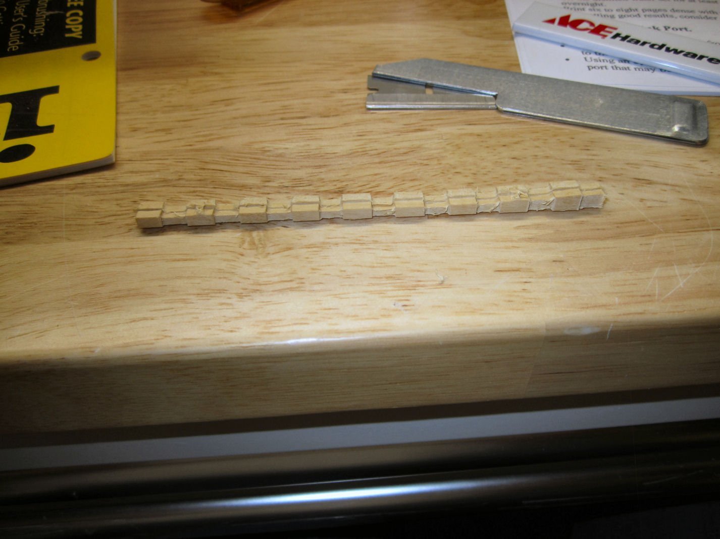
As you can see above, the blank apparently shifted a little when they turned it over to mill the back, and the upper and lower surfaces came out misaligned. Not by much, but after cleanup both the parts were too short by twice the difference in misalignment (had to correct both top and bottom). At least the relative depth of the lands on the false keel are correct. So, I thought, “I can just add a shim between the keel and false keel, to make up the difference.” Looking at the keel. I then discovered that the two rabbets are now also misaligned, height wise, and the keel will sit lower in the assembly jig. Not good! I’m going to write to CAF, and see if they will replace these two parts. Luckily, these were the only parts in that blank.
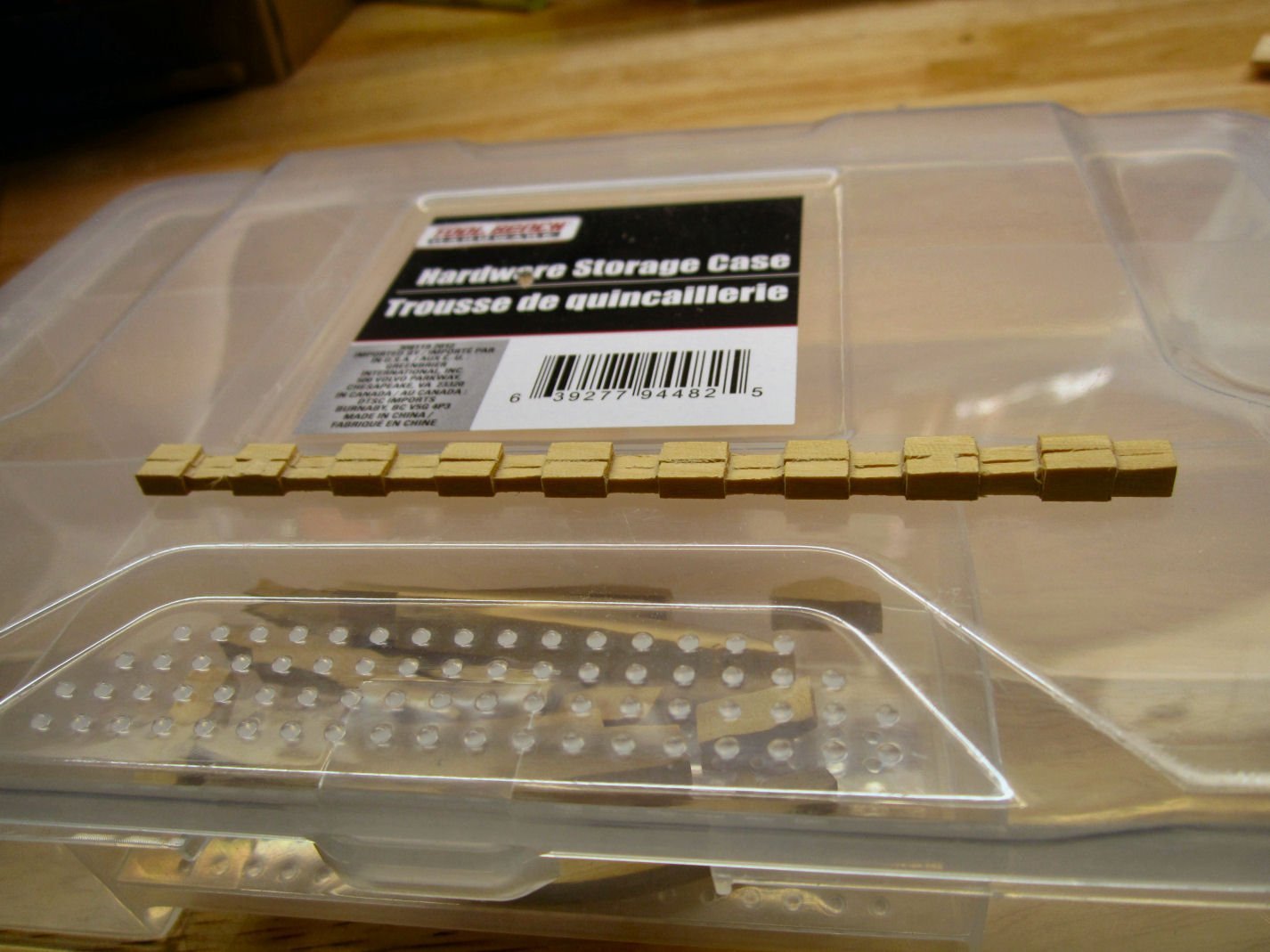
After some cleanup it looked like this,
Now, to continue the frame 6 story, it turns out that, no, the keel would not fit in the frame slot! ********!! I tried widening the slot with files, etc., but was just marking up the underside of the chock, and cutting the frame piece unsquarely. So, out came the Isopropyl alcohol again!
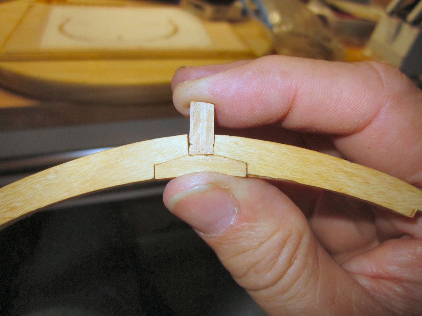
I cleaned up the unsquared area with my disk sander and got everything put back together, with the keel now fitting nicely. Then, for fun, I cutout the bottom piece of the upper half of the frame, and placed it on top of the lower pieces. Double *******! The lower frame curve was too shallow! So once again, do over.
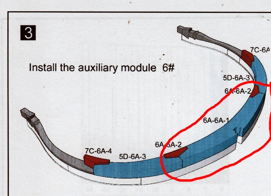
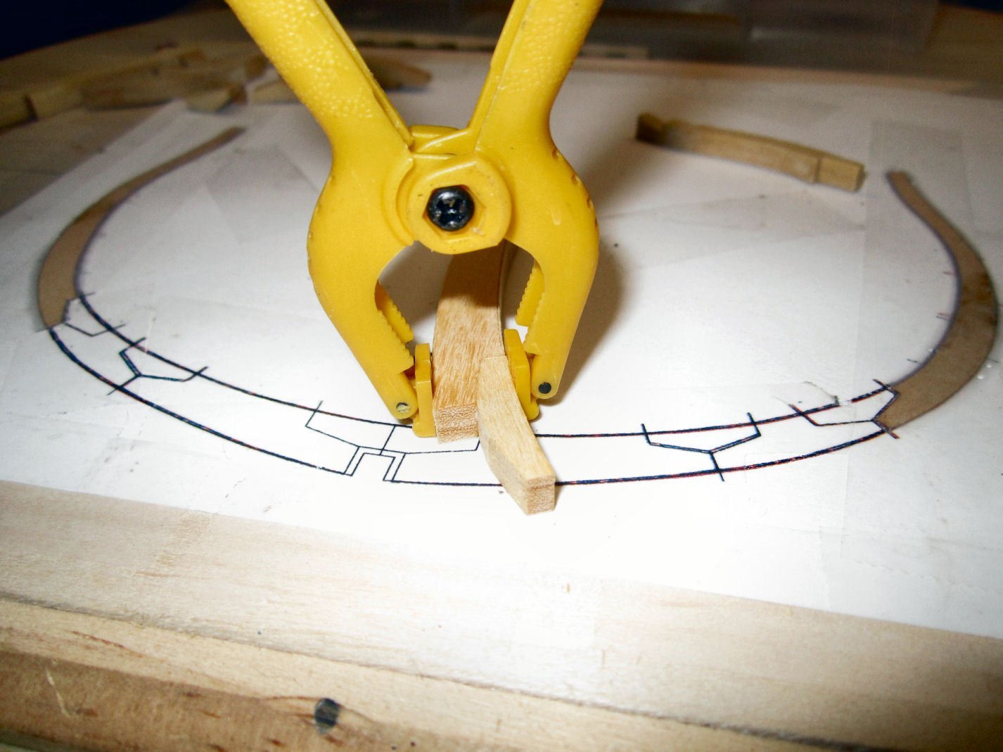
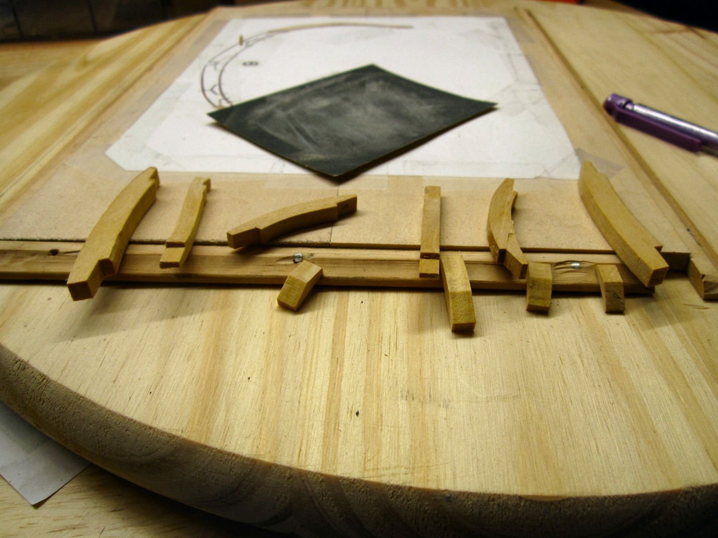
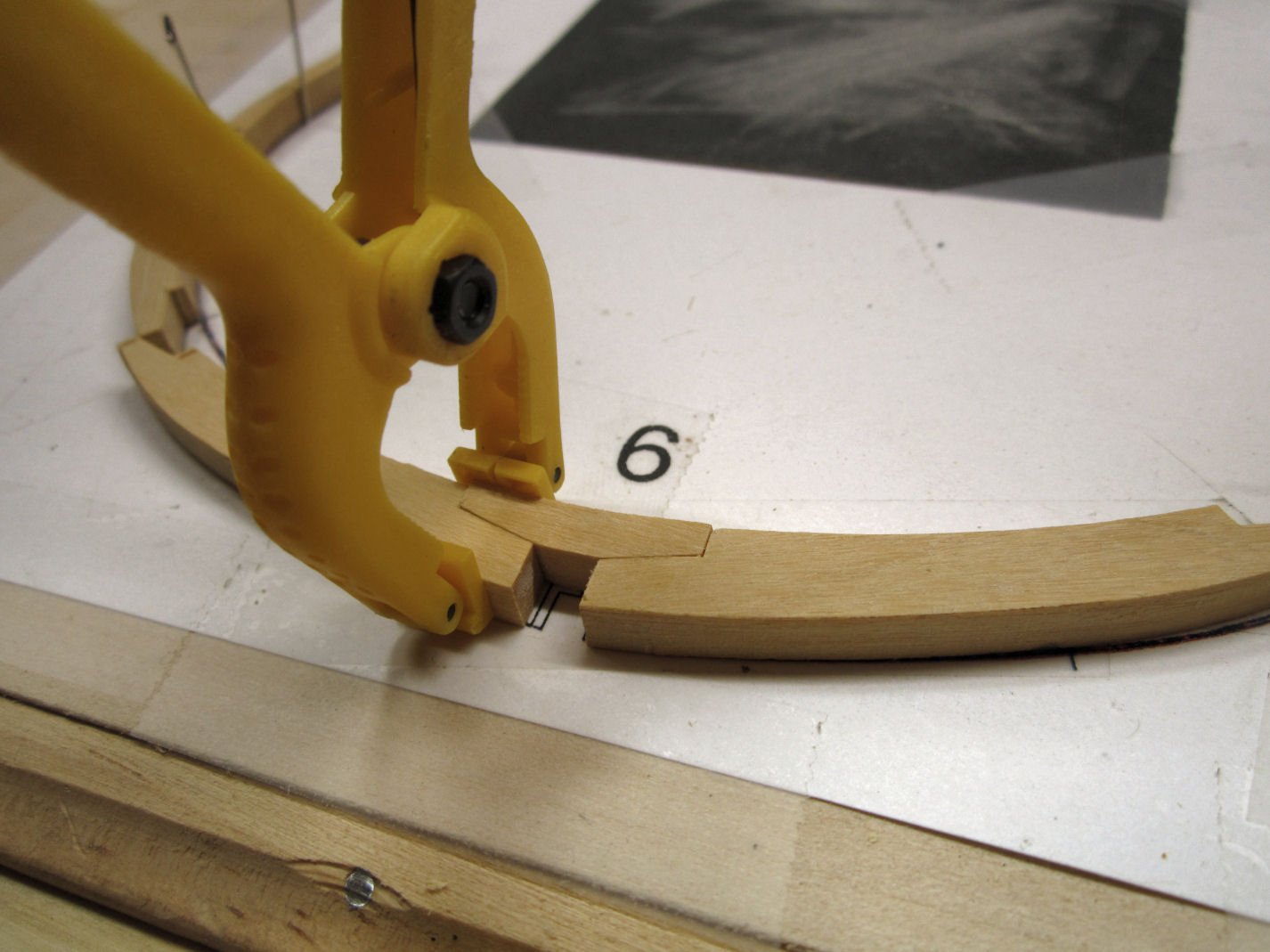
If you look closely you can see that the front assembly, does not have the same curve as the back piece (6A-6A-1). Note however how nicely the edges of the wider sections match. Sigh.

I cleaned up the outside surfaces of the upper piece to remove the attachment points.
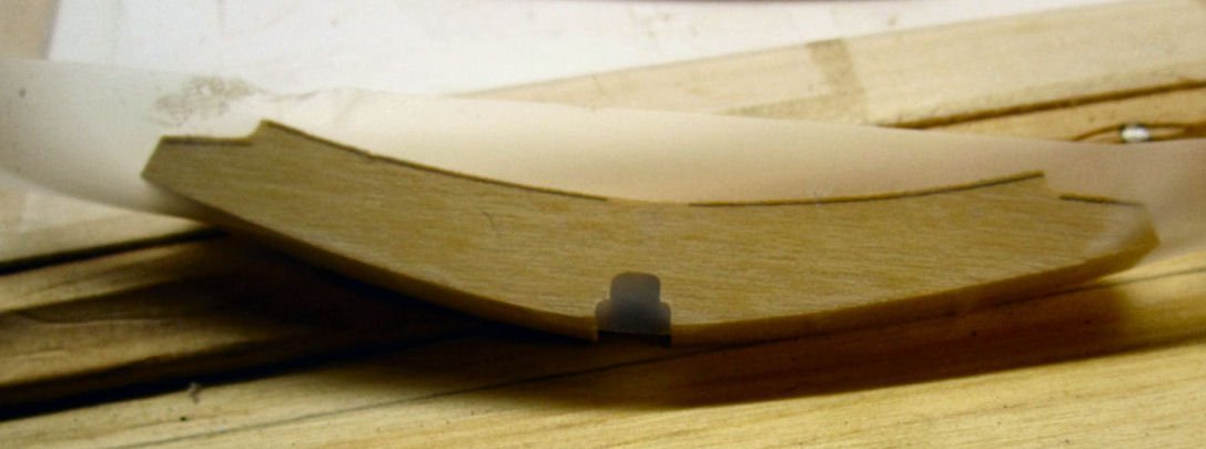
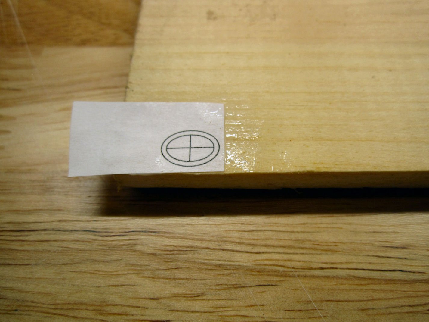
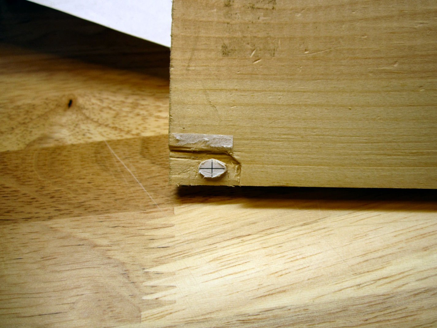
As can be seen in the above picture, I then applied tape to the mating surface of the part, to prevent it from sticking to the lower pieces.
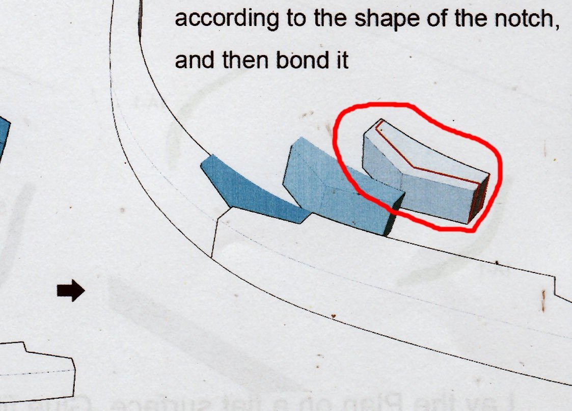
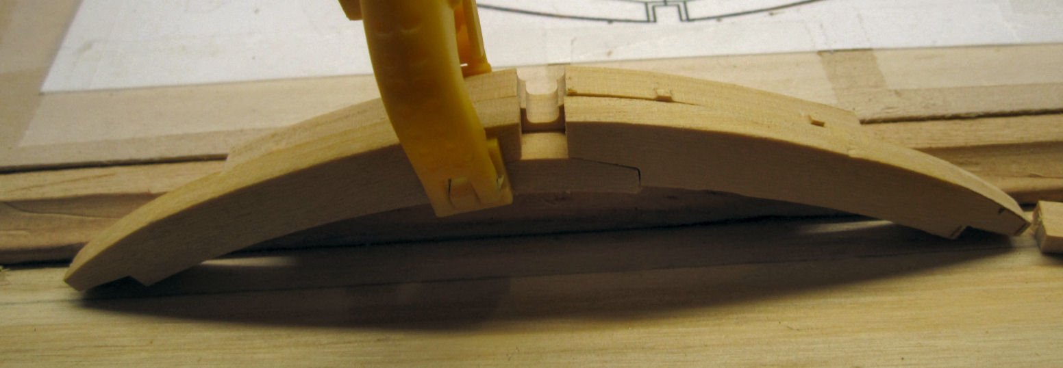
Then I glued the lower pieces in place and clamped the upper piece in place to align them. I had to sand the wedge areas of the chock to lengthen it to fill the longer gap between the two frames. There is enough meat in the part to do this.
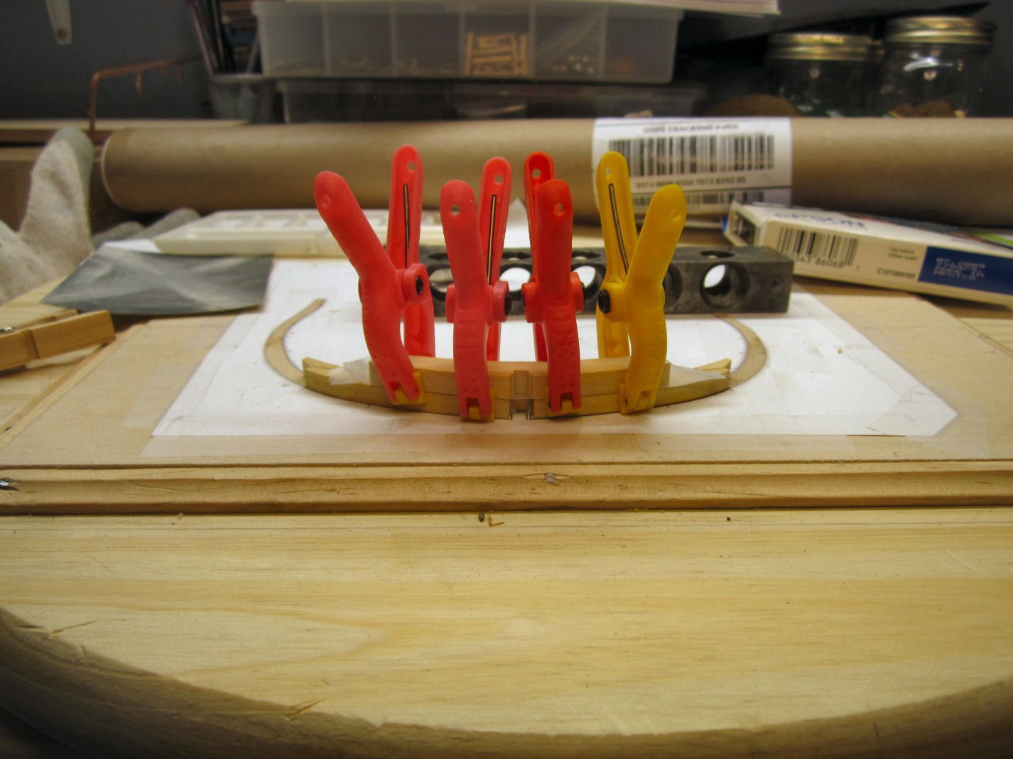
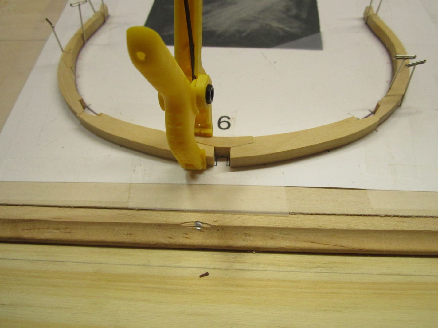
After everything was correctly positioned I clamped the upper section to the lower ones, until the glue had grabbed, then removed the upper section, and placed a weight on the lower parts, to keep them flat.
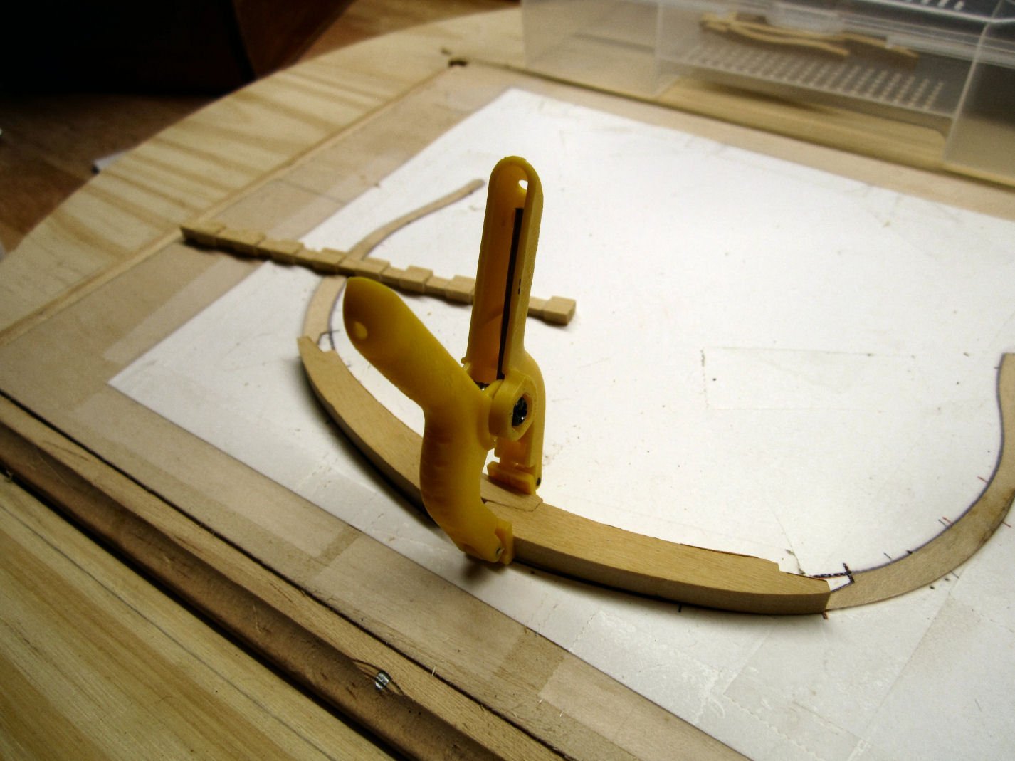
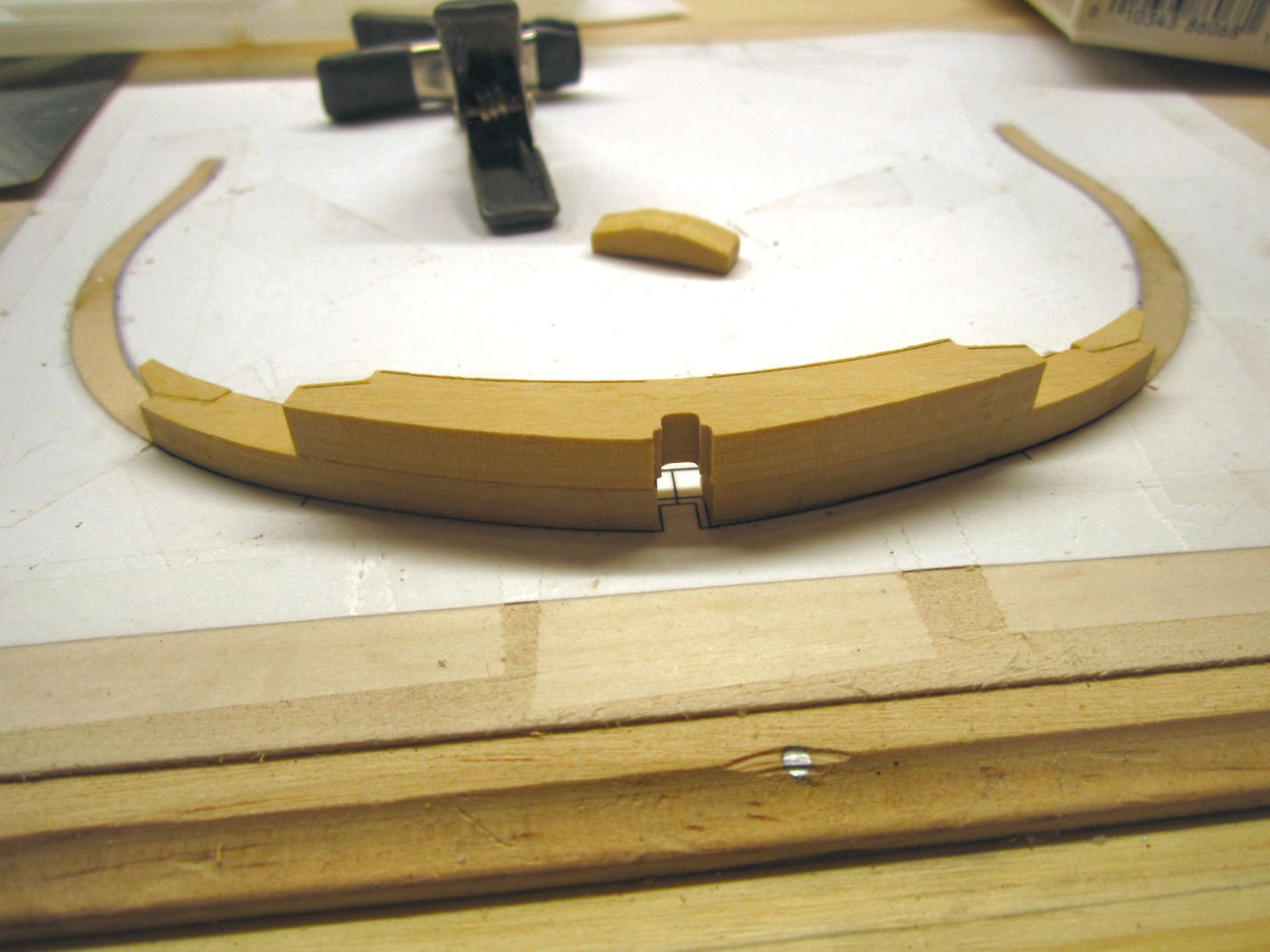
Finally I got the two curves to match, unfortunately, now the keel slot in the bottom half is too wide. Also unfortunately this frame is an end frame, and, naturally, the exposed side. I’ll figure out that problem later.
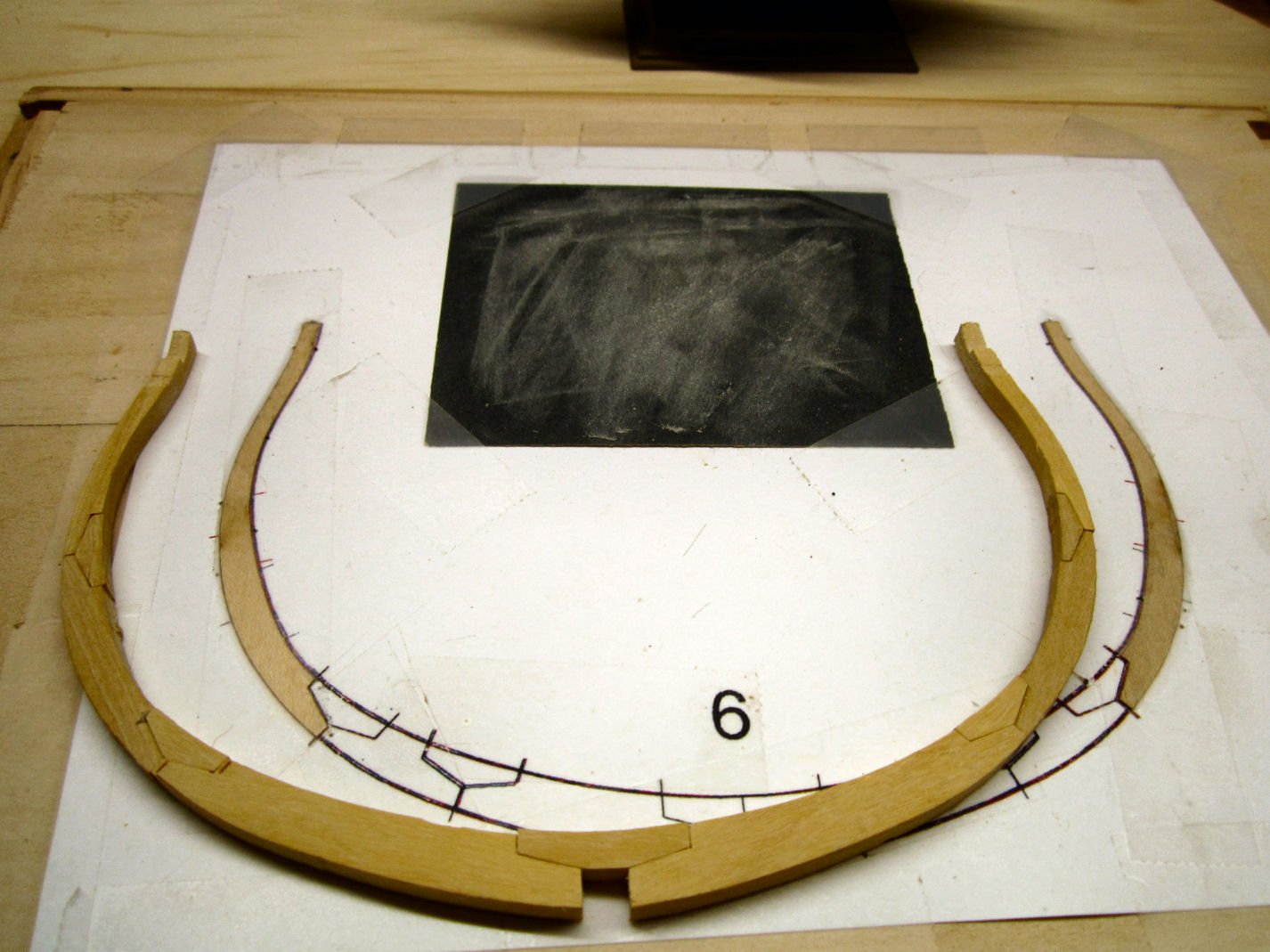
Here is a picture with the bottom section glued back together, and the upper piece set on top. Now the curves match! And, also now, the slots in the lower half are wider than the ones in the upper section.
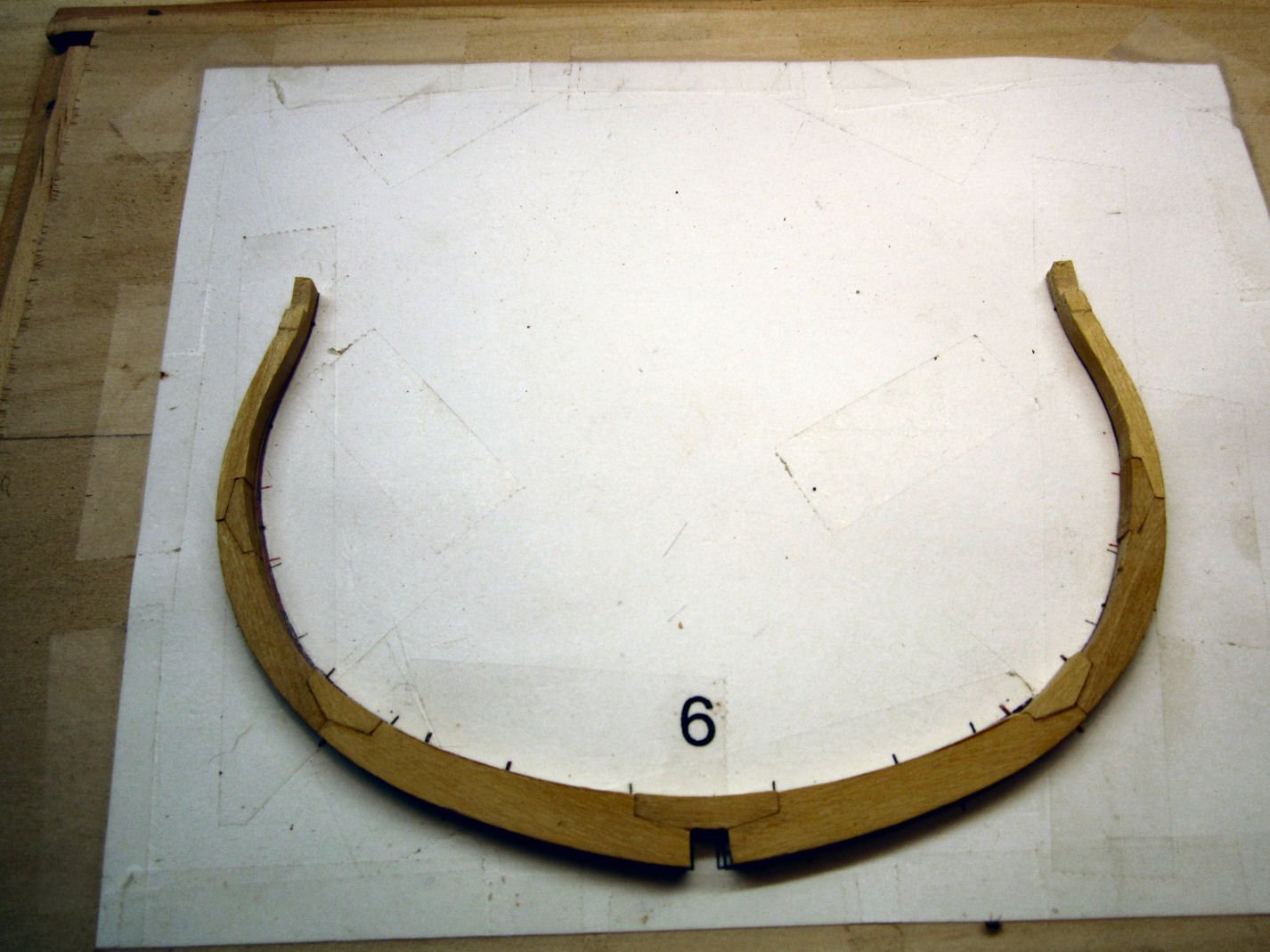
After everything had dried, I glued the rest of the lower Frame 6 parts in place. Finally done with this assembly!
-
-
Great looking model, well done!
- mtaylor and Ryland Craze
-
 2
2
-
Just found this build. Sorry to hear about your back trouble, but I'm glad you are feeling better! Interesting subject.
- Old Collingwood and Canute
-
2
-
Many years ago, I took one of the DUKW tours out of Tampa, FL. After we got out a ways they asked if anyone wanted to drive it. My hand was up so fast, I think I got friction burn from the air resistance! No one else was interested, so I got to drive it for about 20 minutes. Had a wonderful time!
-
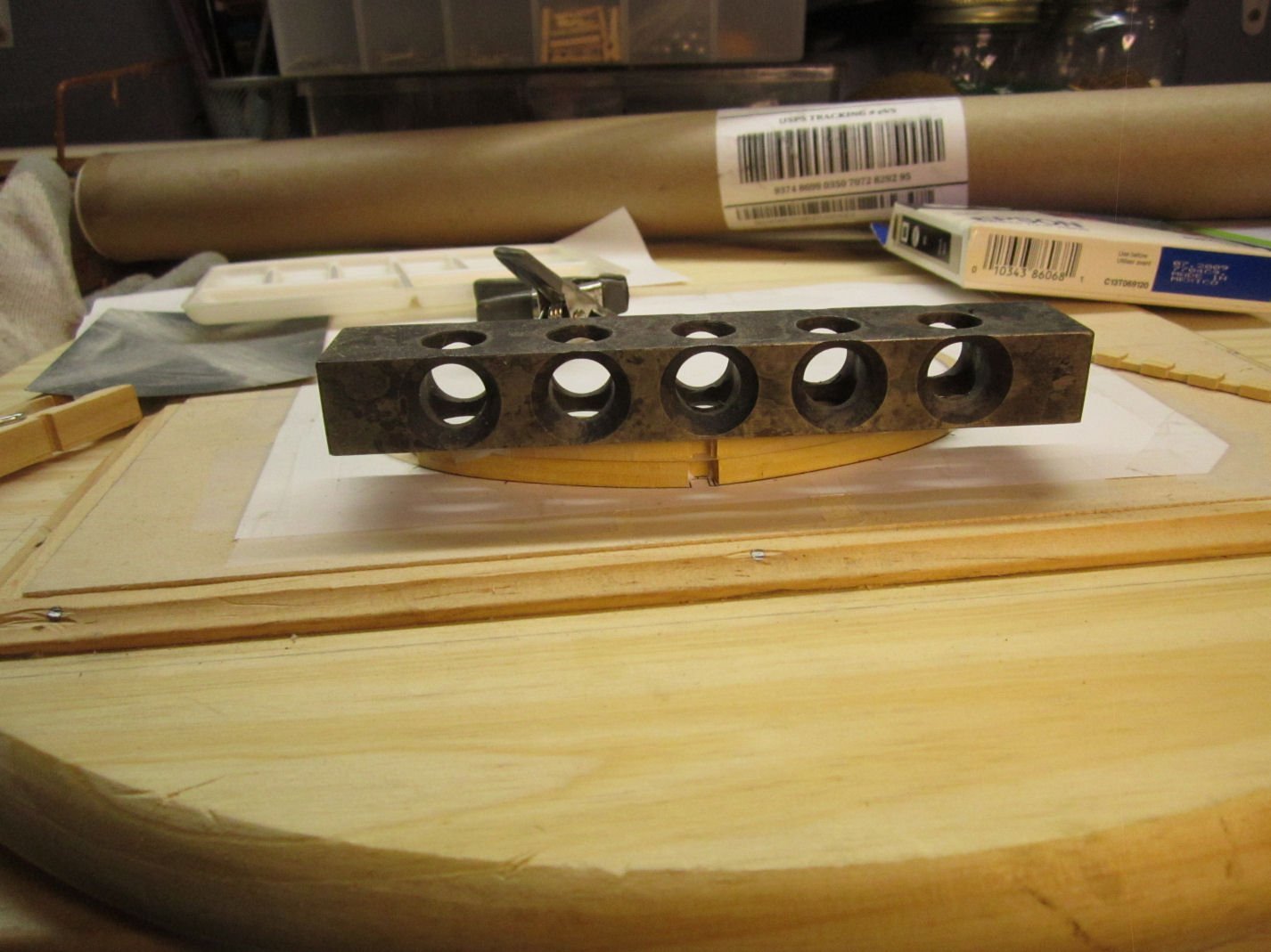
-
Looks like an indexing setup. Place a piece between the centers, and cut X number of flats, or drill X number of equally spaced holes around the circumference. Used with the milling machine. For example make a round bar, into a hex bar, then drilling a hole centered on each face, Drilling four holes in a mast, at 90 degres apart, etc.
-
I don't know how sharp the teeth are on your model, but T-Rex teeth close up were a blunt triangular cross section shape, with serrations on the edges. Designed to hold up to their massive bite, and bone crunching ability. More like a triangular punch. Look up pictures of them.
- Keith Black, Canute, Egilman and 3 others
-
6
-
-
Canopy glue? The plastic modelers use it.
- popeye the sailor, Canute, Egilman and 2 others
-
5
-
I watched a lecture given by the curator of the Wasa museum. They had a replica of one of the cannons cast (I think a 24 pounder), and test fired it against a replica of the side of the Wasa.The cannon ball passed completely through the side of the hull, even if there was a frame in the way! The difference was fewer splinters (the main killer in such a situation), if the ball only hit an area without a frame. He said they calculated that the ball would likely also go through the other side!
- Roger Pellett and mtaylor
-
2
-
Even if you have paint chips, for modern equipment, you may still have problems.
Gray paint, in particular, can vary between batches, even from the same manufacturer. A story I heard in the 70s is: An upper ranking officer was going around and comparing the gray paint on radar units, and almost all of them varied from the paint chip he had . Afterward he sent each installation a paint chip, and ordered them all to repaint the units in the proper color, or else (he used different words, but this is a family forum). At the appointed time he reinspected the units, and all but one still did not match! The other unit maintenance personnel were demoted. Later some of them asked the person in charge of the one that passed, how he did it. He responded that he repainted the chip, at the same time he painted his units.
-
Vallejo makes two types of paint, Model Color (for brushing), and Model Air (prethined for airbrushing). The Model Color can be airbrushed with thinning, but the Model Air has a finer pigment flake size. A majority of the two paints have matching colors.
Their site has charts for color matching the two, as well as matchings for several of the other brands.
- Canute, Jörgen, Old Collingwood and 3 others
-
6
-
-
-
Use very light cloth on the outside, and at least a coat or two of resin on the inside, after the outside is finished.
- mtaylor, allanyed, Roger Pellett and 1 other
-
4
-
Use a marine epoxy type resin, not the polyester (automotive) type resin! The polyester has a tendency to pull away from wood. The marine epoxy type is designed to stick to wood and will stick much better, in the long run. If you find either has trouble setting, heat the hull in a semi sealed container (plastic tub, etc.) in the sun. The resins use chemical heat as part of the setting process, and thin sections may not generate enough heat to do the job. You may have to paint on a second coat of just resin, after sanding.
- mtaylor, mikegr, Roger Pellett and 2 others
-
5
-
I should have started with the bottom parts, and fit them between the shims, then built the upper sections.
- Matt D, Canute, Old Collingwood and 1 other
-
4
-
PART 16
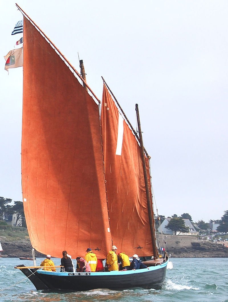
Now that the traveler is fixed, I mounted the hull onto the plastic stand, using Canopy Glue. The Canopy Glue dries crystal clear, and doesn’t damage the paint.
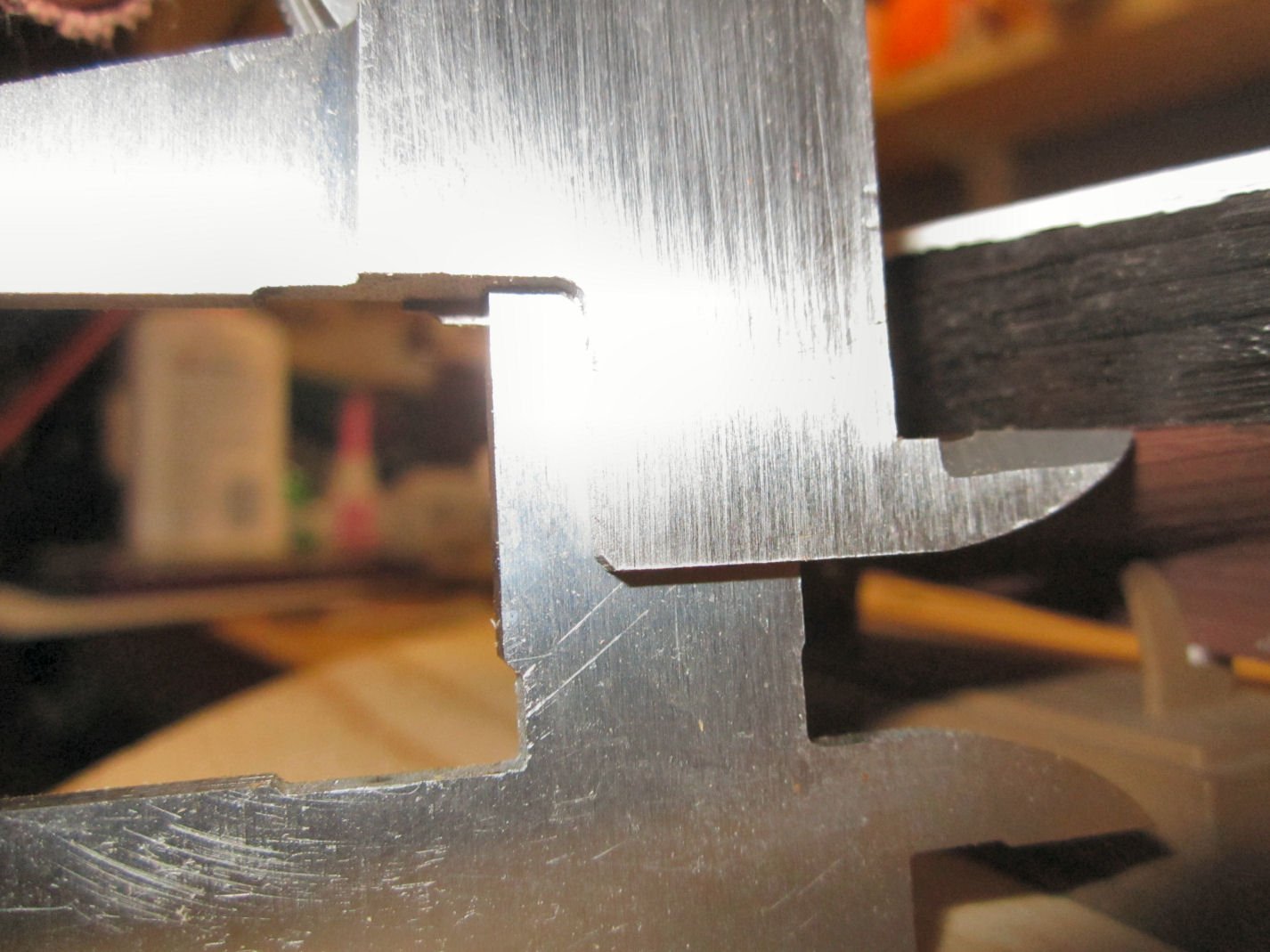
First I placed the hull on the stand, until it looked level. Then I measured the waterline at the middle of the hull using a pair of calipers.
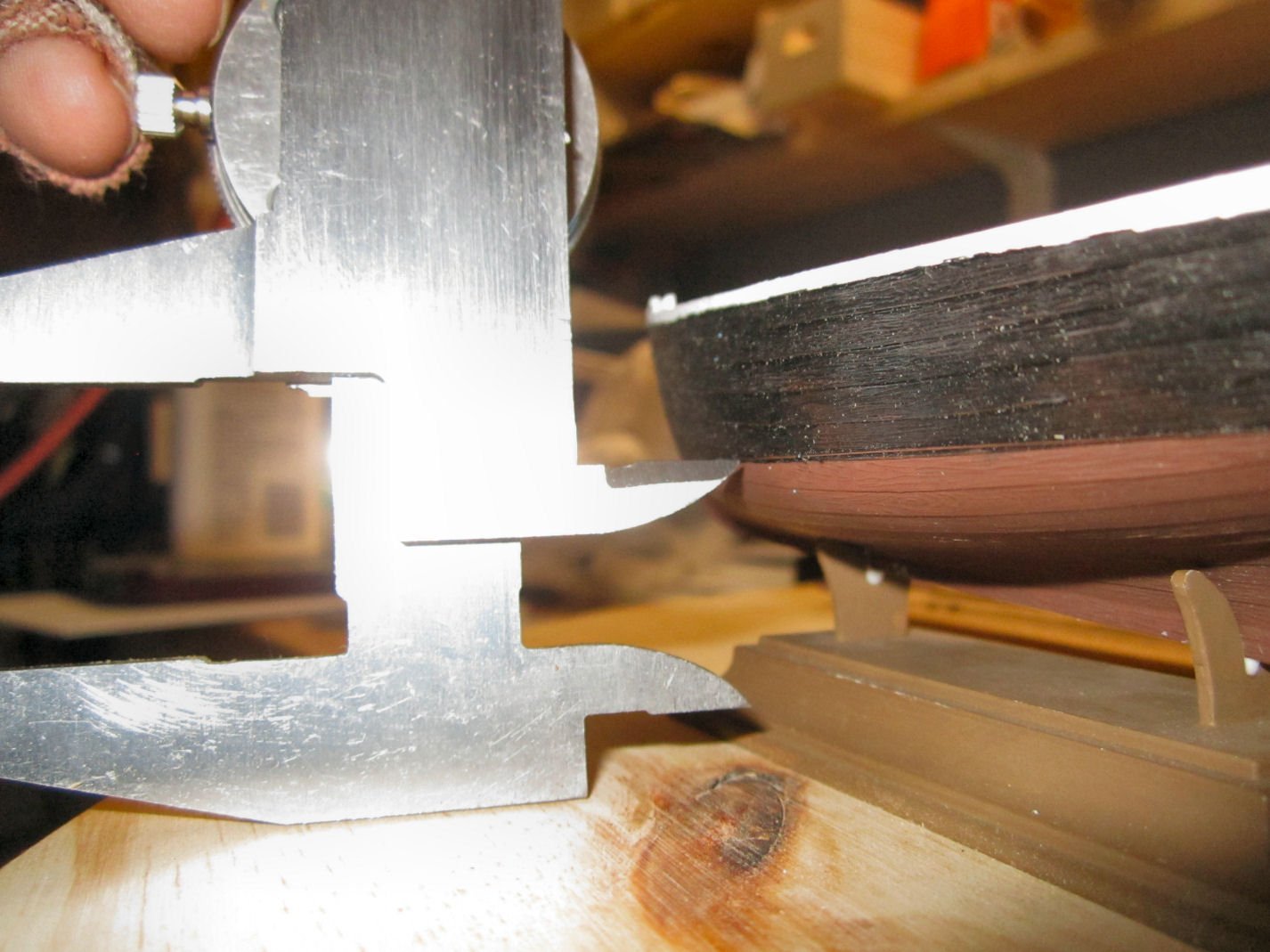
I then moved them to the back and front of the hull, and compared them to the waterlines there. I slid the hull along the base (which has two different height pedestals), to raise the lower end. After a couple iterations of this the waterline was level. I did not put the masts in to check that they were vertical, as the pedestal contacts both sides of the hull tightly. For a bigger or better model, I would have, but did not feel like shimming, or trimming the painted base. You can see the two spots of fresh glue, in the pictures.
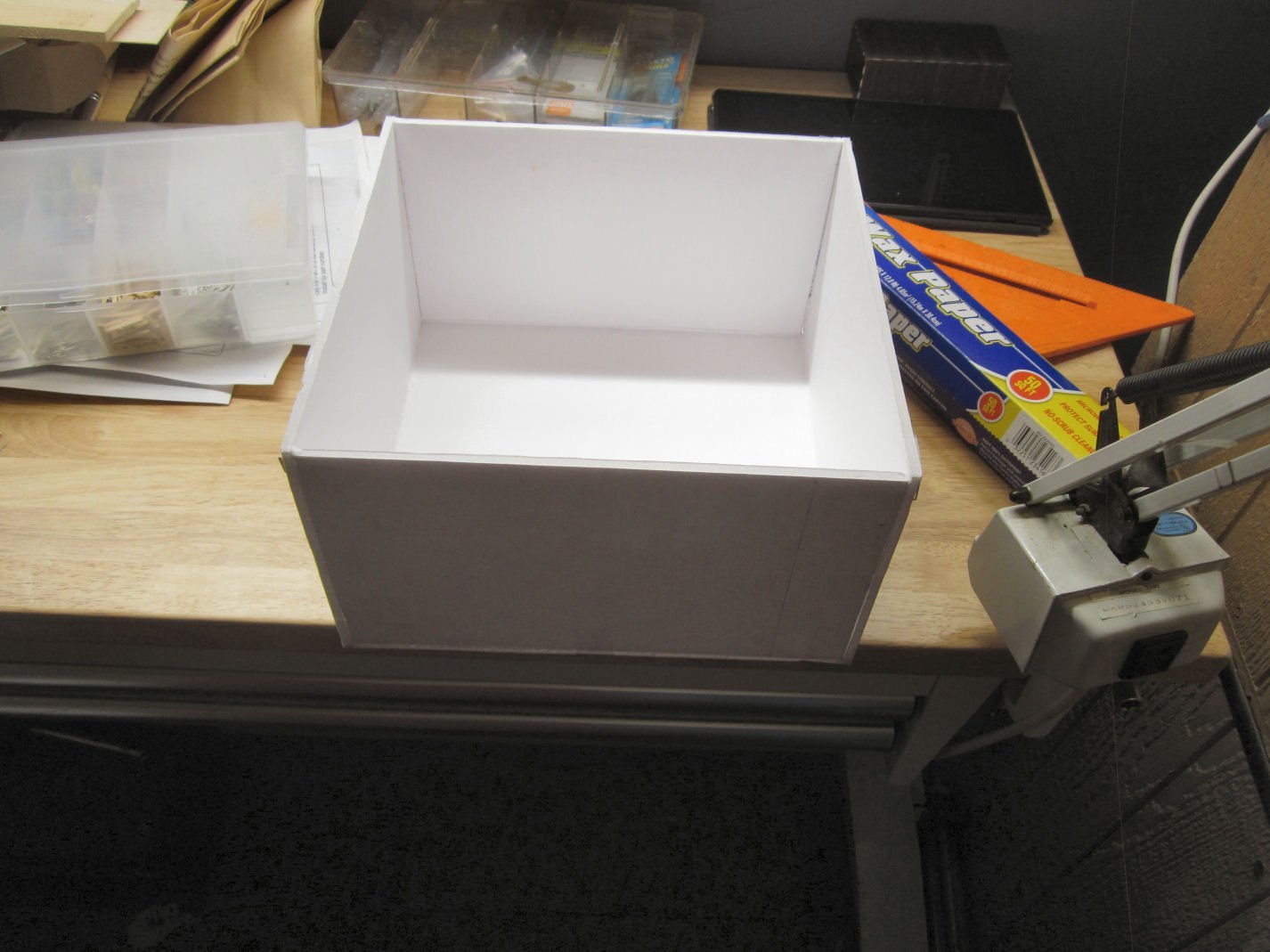
Now that I’ve gotten to the point of adding the spars, I needed some sort of temporary protective “cabinet” to store the boat in between building sessions. For this small model I decided to use foam core board. After a trip to the store to pick up a couple sheets, I was ready.
The model measures just short of 8.5” long and 8.3” tall. The spars and sails run parallel to the length of the hull, which is only about 2.5” to 3” wide. I set the cabinet dimensions at 10” long x 10” tall and 6” wide, on the inside. I cut the back, ends, sides, top, and bottom pieces accordingly. There is no front piece, as this is just to protect the model from bumps, not dust. I store it in the covered spray booth, so dust isn’t a problem.
I assembled the box using tape to hold it together (as well as a few “T” pins), and ran a bead of wood glue down the inside edges. To keep the glue from dripping all over the place, I did a few edges at a time so they could be level until the glue set. Allowing for drying time, this took a couple days. When all the glue was set, I had to add a second coat of glue to a couple of the edges.
While the glue in the cabinet set, I built a sliding base for the model to sit on, and allow for removal to work on it. I cut this base slightly smaller than the inside of the cabinet, and put the boat on it, so I could figure out where it had to sit. I marked the position of both ends of the plastic base, and pulled it out and removed the boat. Then I glued pieces of foam board at these marks, as well as at the back, so the base would be centered front to back. I held them with pins, until the glue had set. Then I added two more pieces at the base ends, that overhung the lip of the base, to lock it lightly in place. I can still slide the plastic base out, to work on it, as needed.
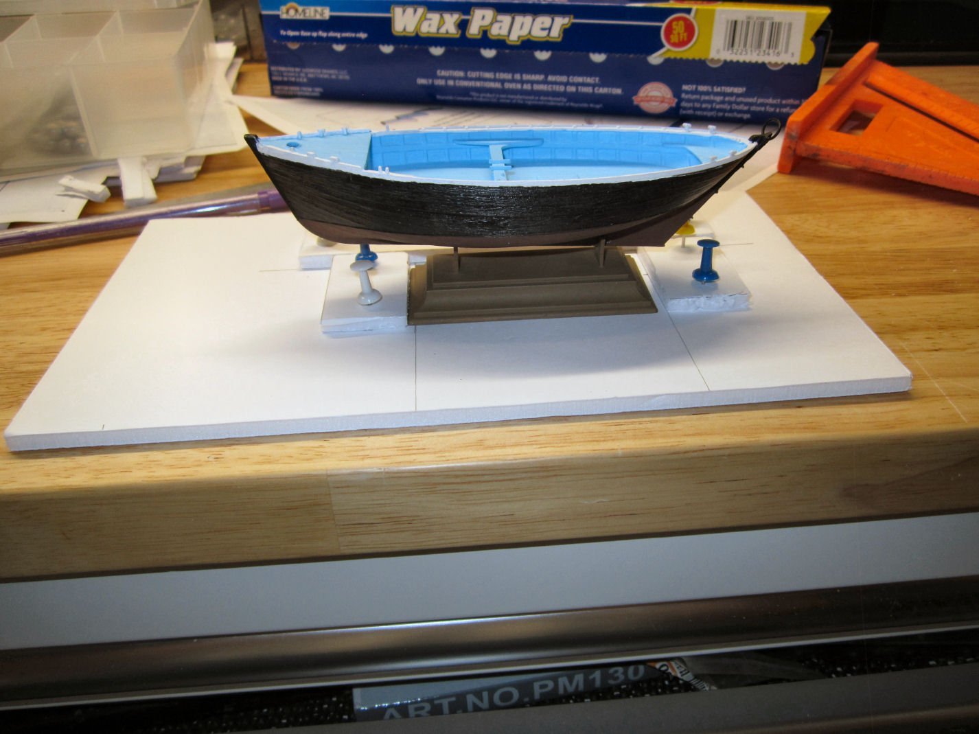
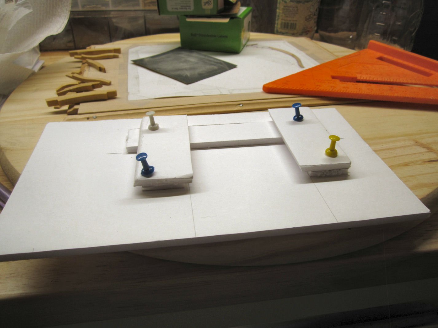
While the glue was setting, I put the base piece back in and glued two layers of foam board inside the cabinet ends to hold the base in, but still allow it to slide out.
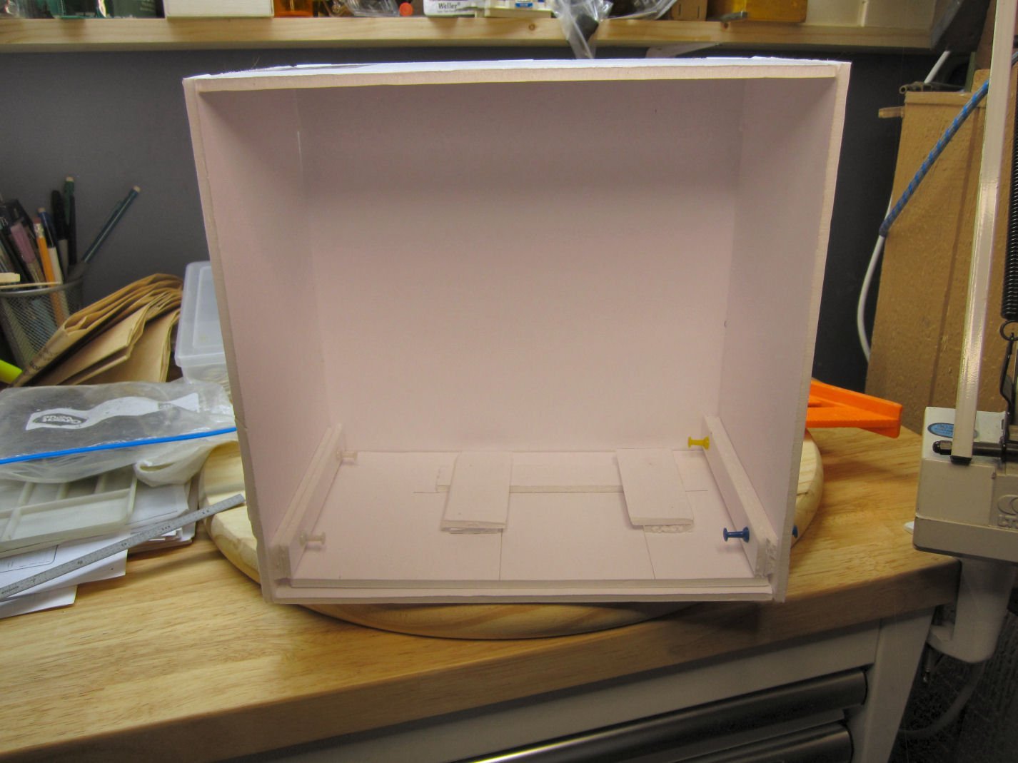
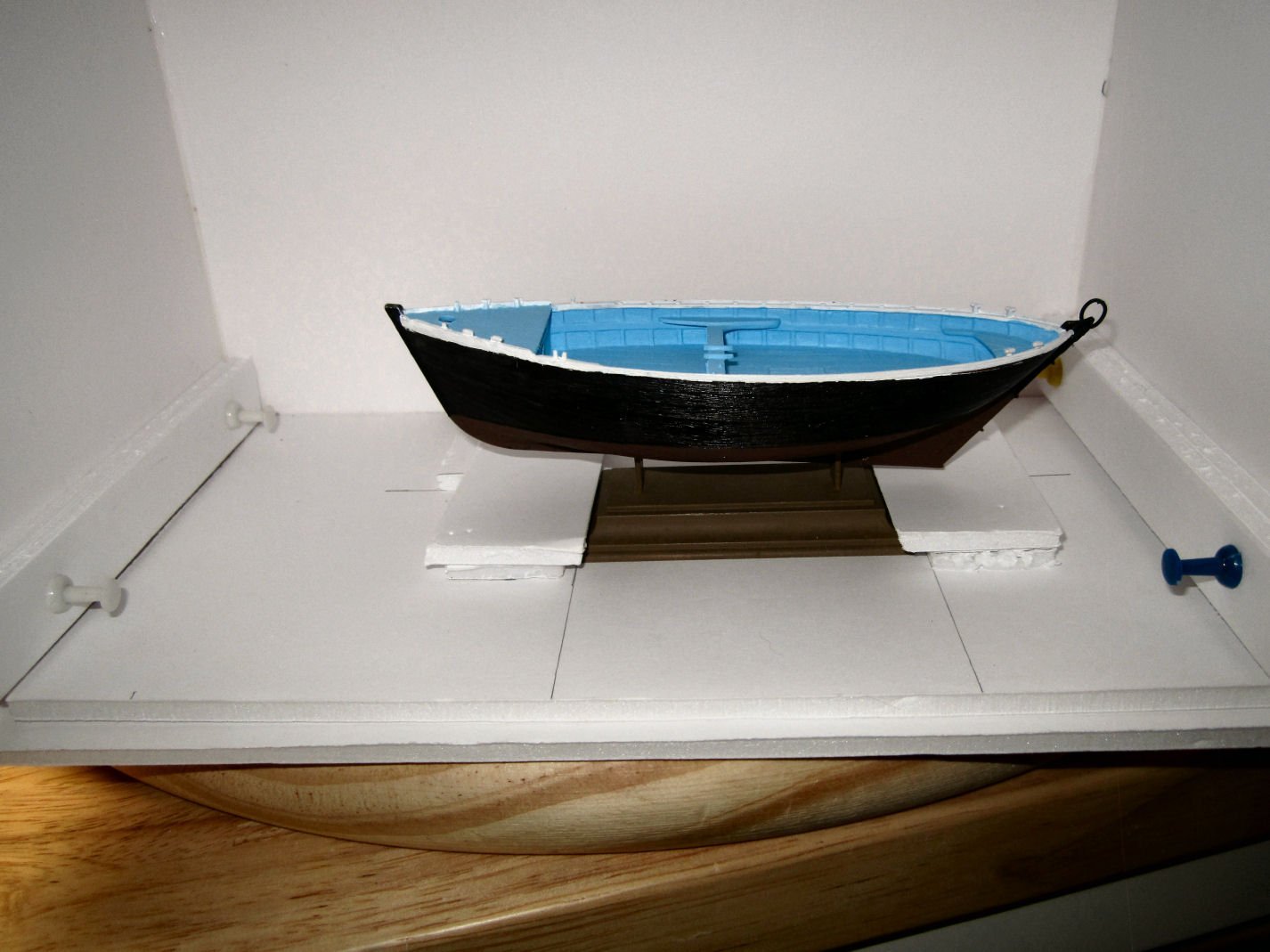
Here is the boat in the cabinet, ready for me to continue.
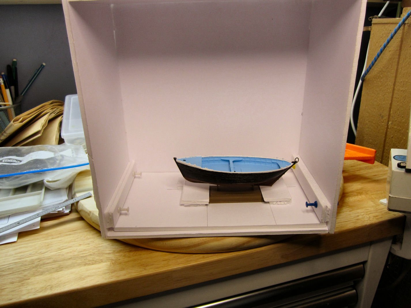
Total cost of the foam board was $.88. For a larger, or more delicate model, I would probably use 5MM plywood, but for smaller ones like this, it will work fine.
I have a cheap plastic model enclosure in the mail to put it in when finished. I need to clean out and rearrange my display cases, then it will be put one of them, without the cheap case, which will be barely big enough for it. I couldn’t see spending $40 or more for a case, for a cheap model, that can sit perfectly well in my nice glass display cases.
-
Part 007
Well two steps forward and one back, a little better than the other way around. As I mentioned last time, Frame 6 would not fit back between the shims when I tried to put it back into place. The only solution was to unglue all the parts (I found a couple other mistakes, and will correct them all at once), and start over with building it.
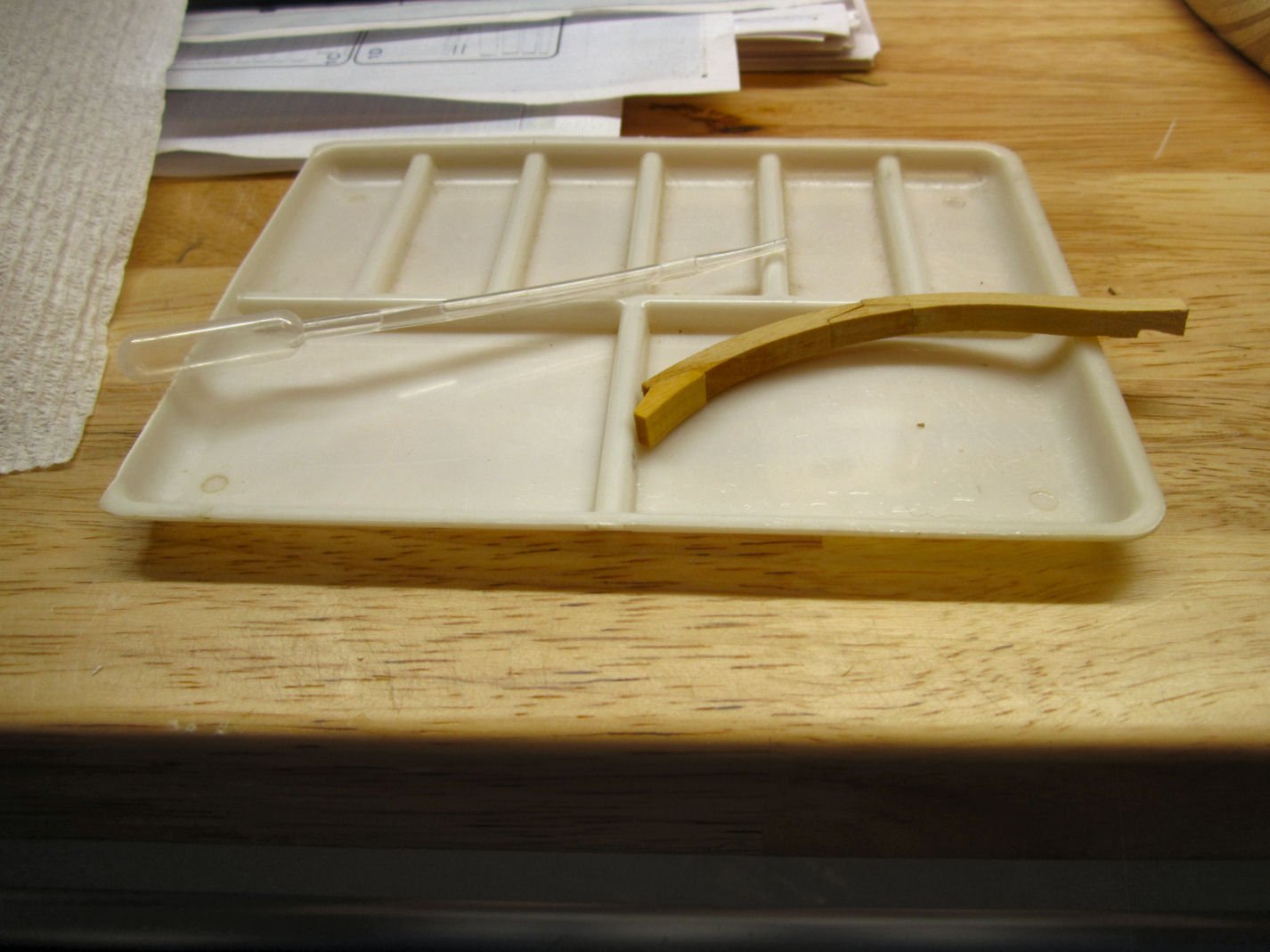
I softened the glue joints (Elmers) by soaking them with 90% Isopropyl Alcohol. To do this I held the joint over a plastic tray and dribbled the alcohol over the joint using a pipette. I’d dribble a little on, let it soak in, then turn the frame over, and hit the other side. I’d wait a few seconds and do it again. I generally did this 3 or 4 times. After allowing a minute or so I’d try the joint, and continue if it wouldn’t separate under moderate pressure. Most of the joints yielded after a couple of tries, but some took 5 to 10 minutes of effort.
When a joint would separate, I then scraped it with my fingernail to get as much of the glue off as I could.
I’m letting the pieces dry for a few days, and will start over.
- mtaylor, Old Collingwood, Canute and 3 others
-
6
-
-
PART 15
Well, I’ve finally finished the major part of my shop renovations, and can now get back to modeling.
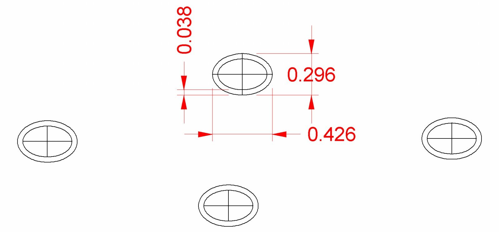
I mentioned in a previous post, that the plastic traveler on the stern had broken, and further deteriorated as I tried to reglue it. I measured the pieces and drew it out in my CAD program. It is oval/elliptical shaped, and dimensioned as shown.

I printed this out, cut one oval out, and glued it to a piece of basswood.
Then I used some small chisels, and a hobby knife to carve out around the print.
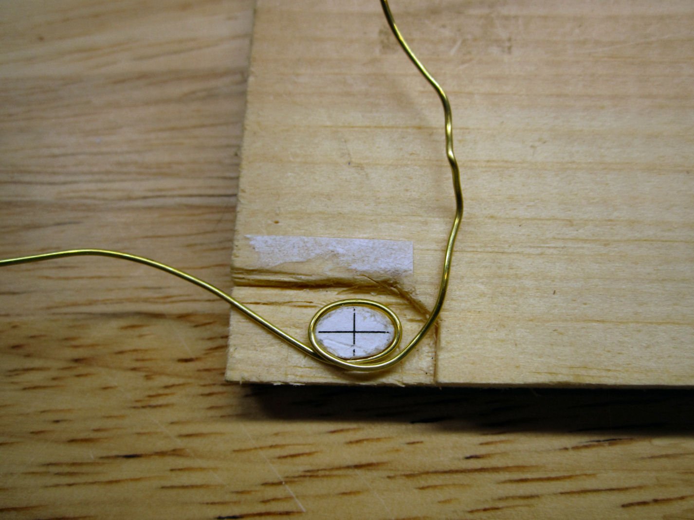
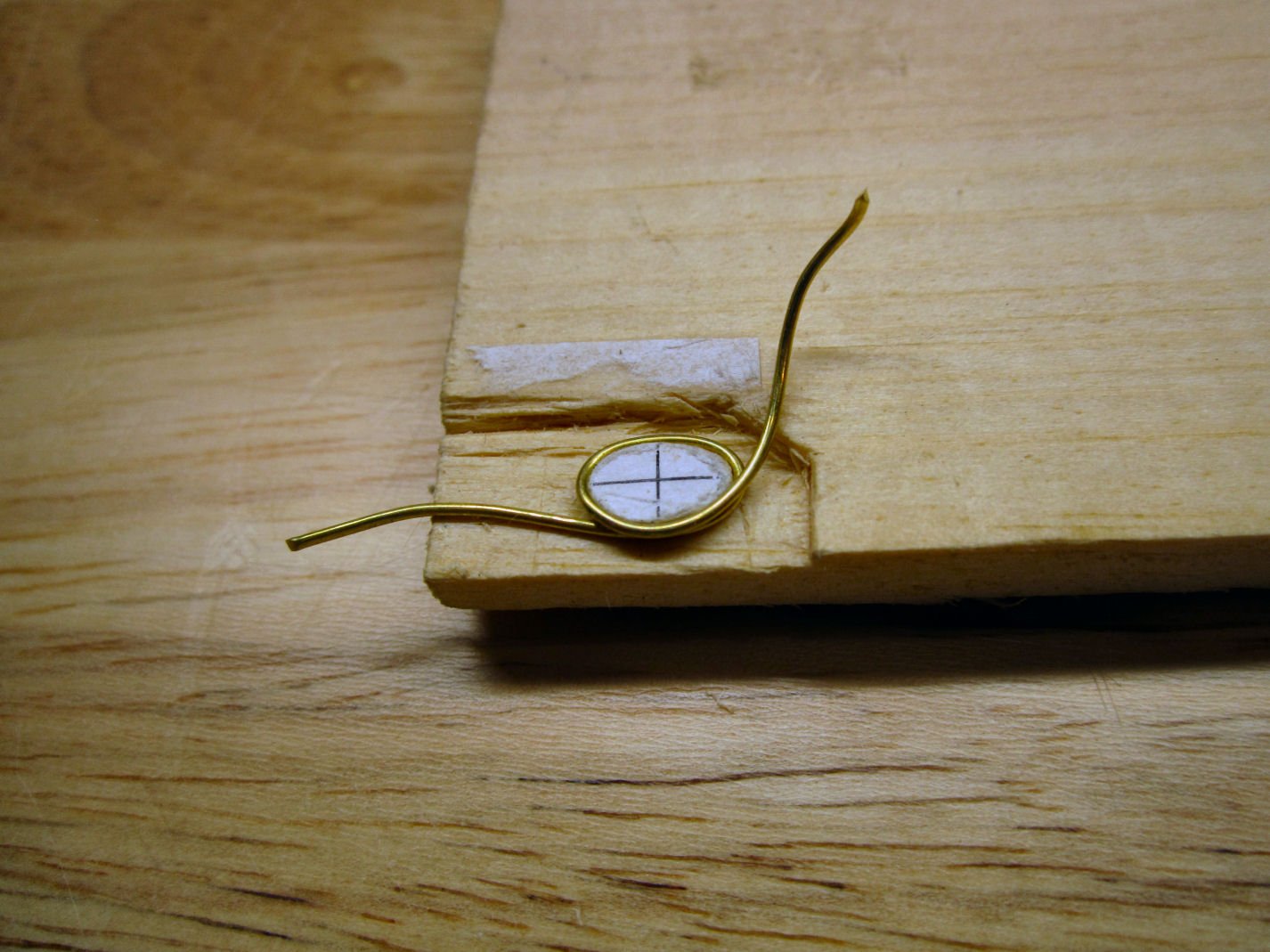
Next I took 20GA Dead Soft Brass Wire, and coiled it around the pattern. While 20GA is way too large for the traveler in real life, it matches the diameter of the broke plastic part. The flattened iron attachments are already installed and I needed the wire to match the drilled out stubs in these parts. I was, also, not sure that thinner wire would hold up during handling, as this part is very exposed.
I had originally thought to carve the straps off the stern. The wire was still too hard to flatten easily, and several failed attempts at bending the wire at the bottom of the loop, while getting everything symmetrical convinced me to go with just replacing the loop.
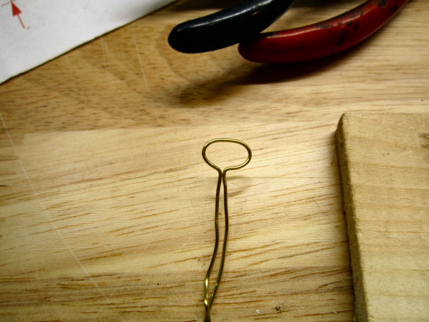
So I made a new loop, and cut the wire at the bottom, rather than bending it.
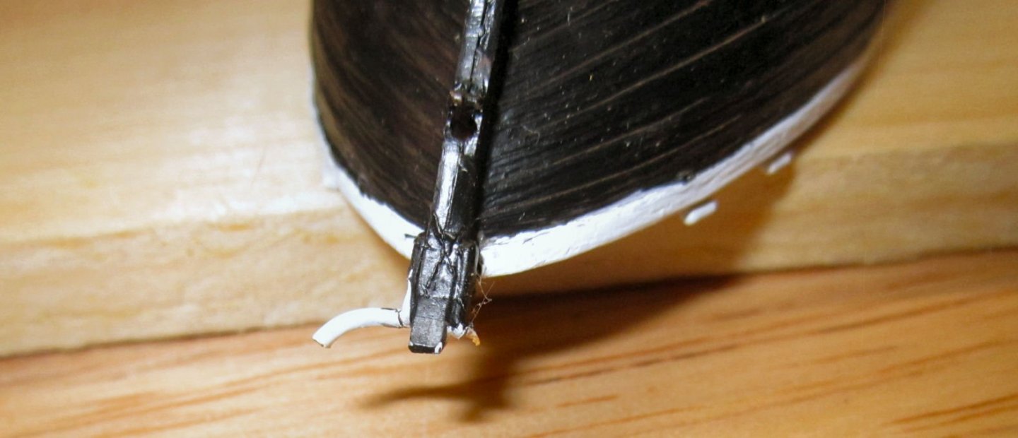
The next picture, is the remains of the plastic part.
I trimmed them flush, used a pick to center mark them, and drilled through with a series of wire drills, to a few thousands larger than the wire.
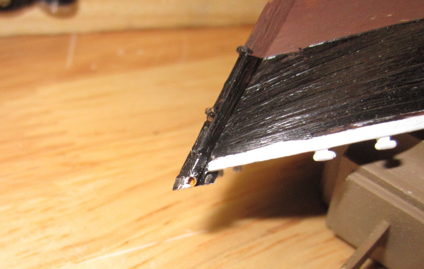
Then I put the ends of the loop, into the holes from each side and used CA to fasten it. It is not perfect, but looks good from a distance.
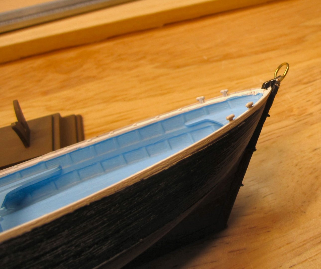
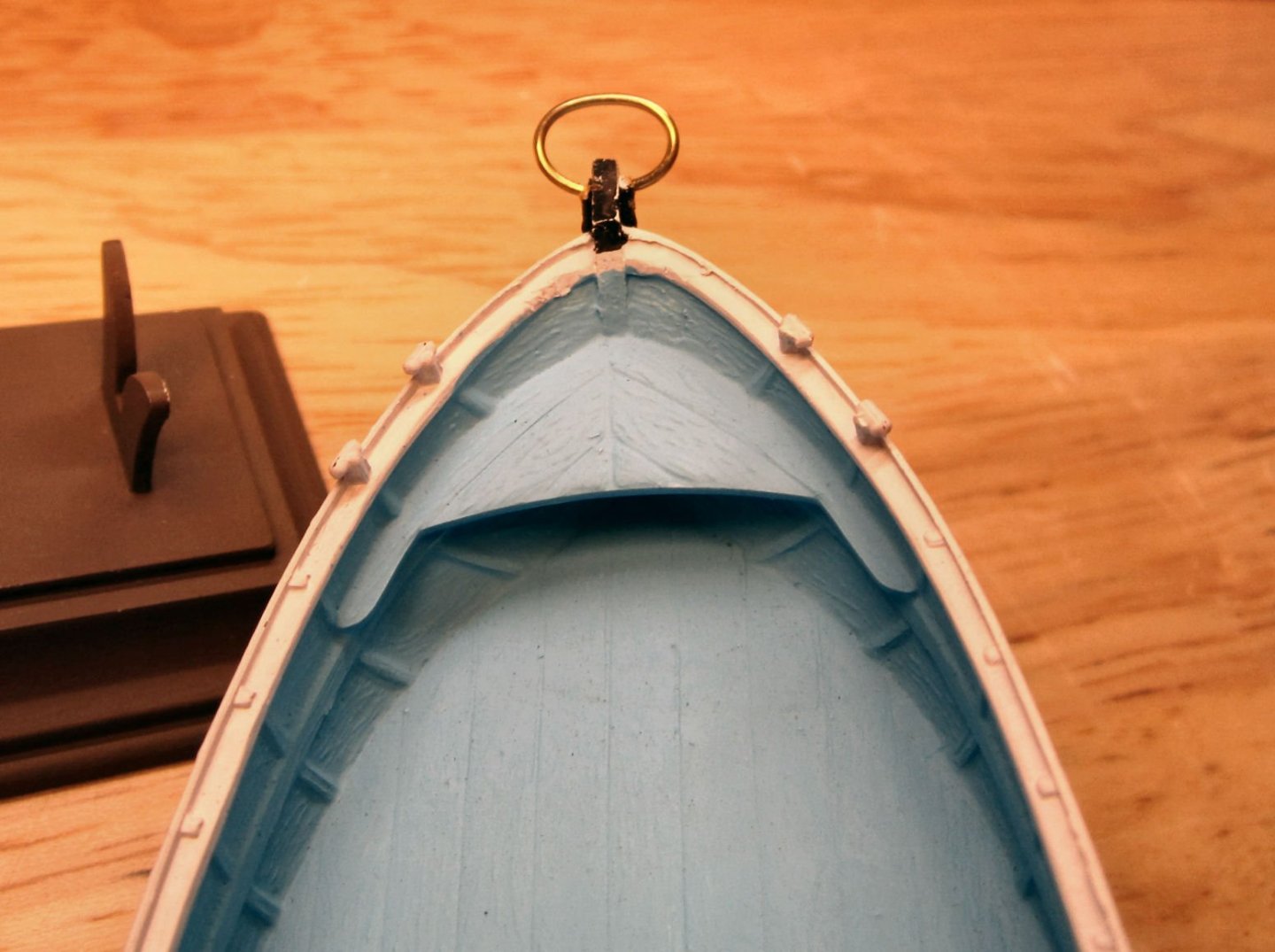
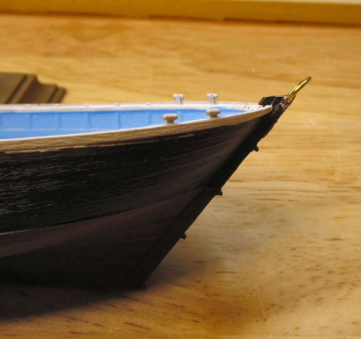
I painted it with a couple of coats of black Stynylrez primer, brushed on.
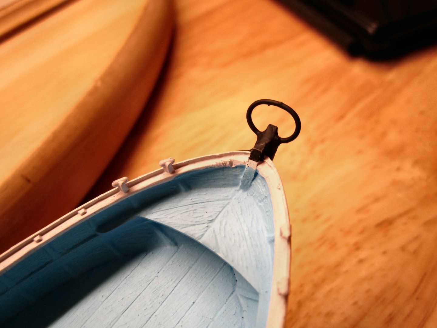
It looks as good as the original part. I may leave it black, or paint it white, like in the box art, but photos show either color used on existing boats, and it is already overly thick. I do have to trim that little blob of paint on the inside of the loop, though.
- Haliburton and yvesvidal
-
2
-
Welcome aboard!
- Stevinne, mtaylor, Ryland Craze and 1 other
-
4
-
Part 006
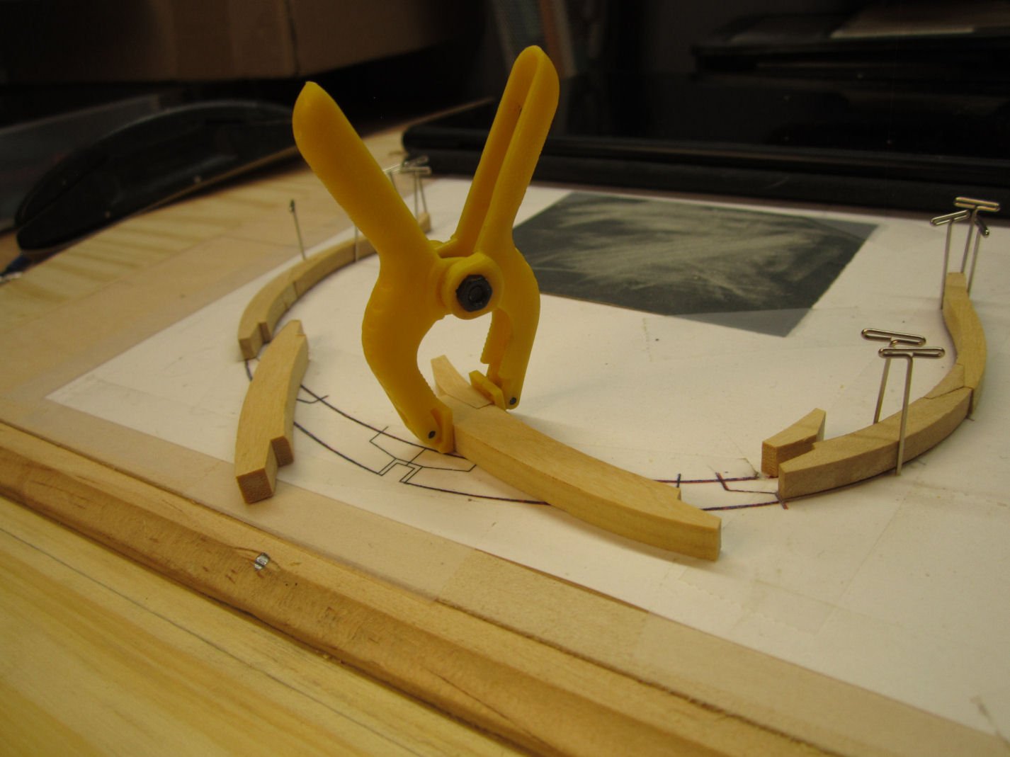
I continued on with building Frame 6, by assembling the other upper timbers, on the other side.
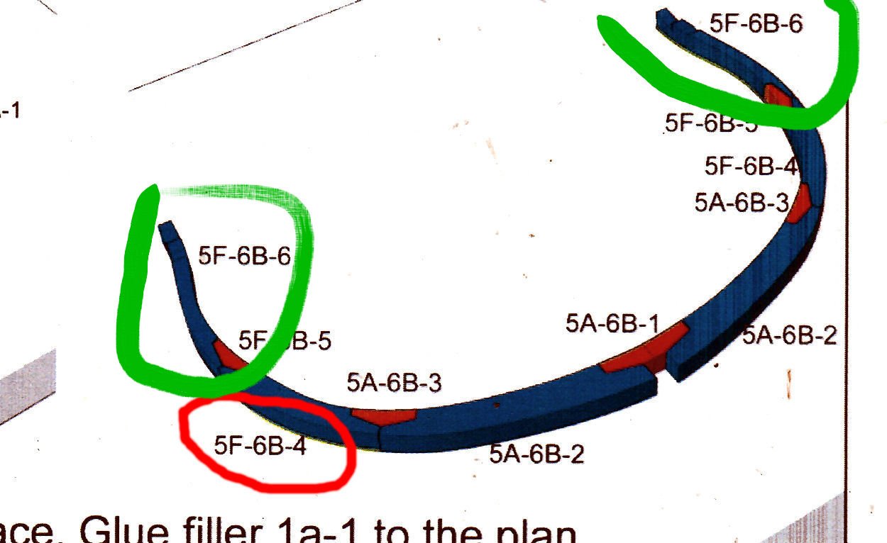
A warning note: The instructions call both upper timbers Part 5F-6B-6 but those parts are mirror images of each other, so look carefully at the drawing in the instructions, to make sure you are putting them in the correct position. The carved surfaces are installed facing up.
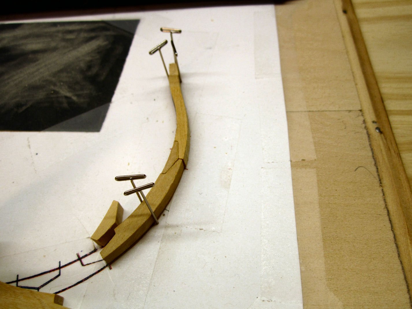
I continued by assembling the bottom sections of the frame.
Note two mistakes I made. First, I should have left the frame in place, as the next step is to build the other half of the frame on top of this section. Luckily I did make the first mistake, as when I went to put the frame back in place. I found that the lower half would not fit back on the sheet! It was too wide to fit between the two shim pieces!
Tomorrow, I will get some Isopropyl Alcohol and soften the glue between the chocks and the upper halves of the frames. After I trim the beam ends so all will fit where they should, I’ll fix this.
From now on I will build the bottoms of the frames first.
- Canute, Old Collingwood, JeffT and 2 others
-
5


New member from the North Atlantic
in New member Introductions
Posted
Welcome!