


thibaultron
-
Posts
2,728 -
Joined
-
Last visited
Content Type
Profiles
Forums
Gallery
Events
Posts posted by thibaultron
-
-
-
-
As the hull is made from plywood, all the hull sections would be runs of curved (lenghtwise), but flat (cross) sections. You could draw bulkheads using the supplied info, as all the hull sections would be flat between the lines (as is the one section shown. A model could be made from these lines, but if you are looking to make a full sized boat, you will need better plans.
-
This reminds me of the USS Monitor. She was rediscovered, I believe in the 70s, upside down on the ocean bottom, mostly intact. Then the government experts chimed in. The location was too exposed to shipping , the currents were too strong, the wreck too fragile! two decades later, all that was left was the iron work, and they only recovered the turret, engines, and some of the plate, the wood they were so concerned with preserving had fallen apart, anyway. They could have at least done extensive photo work.
-
-
- BobG, chris watton, KentM and 2 others
-
 5
5
-
-
Part 010
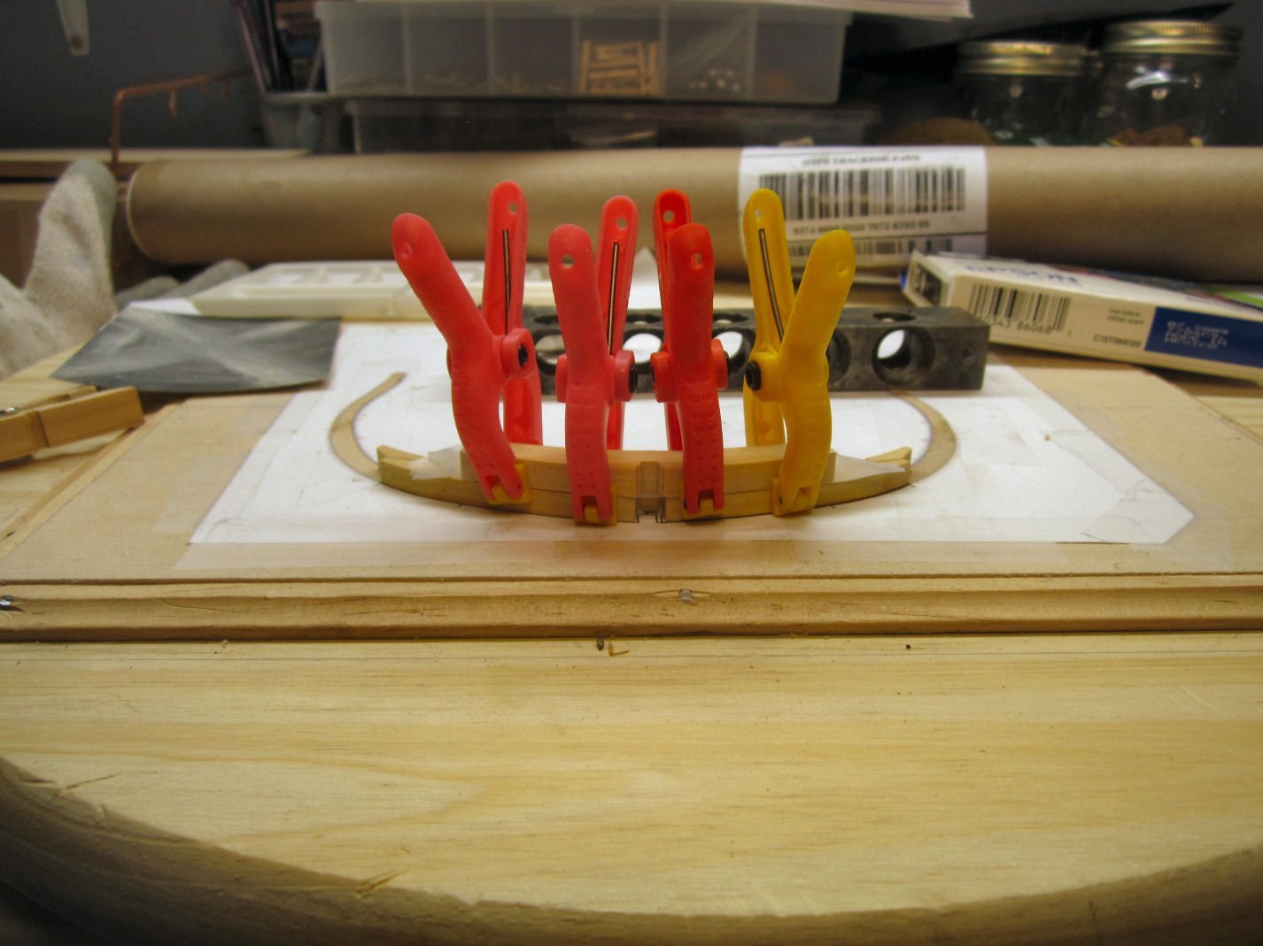
Next I removed the resin inserts and trimmed off the heads, then reinstalled the tail pieces.
I installed the larger of the blocks that tie the tips of the two halves together.
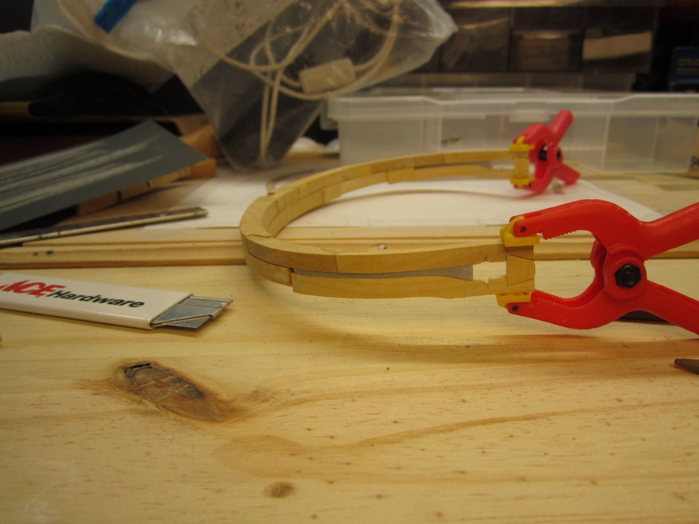
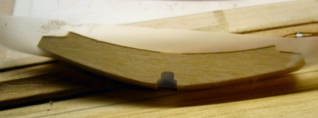
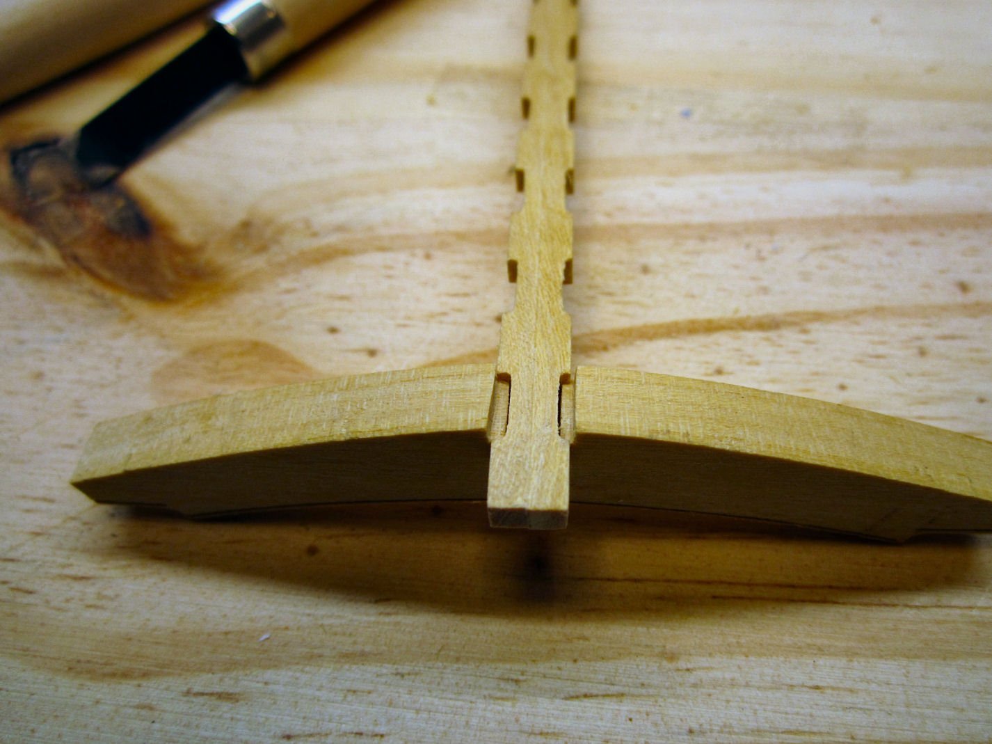
Then I installed the thin piece, that goes below it. This is a laser cut plywood piece, and I had to sand bevels on each end so that they could slide into the groves in the frame.
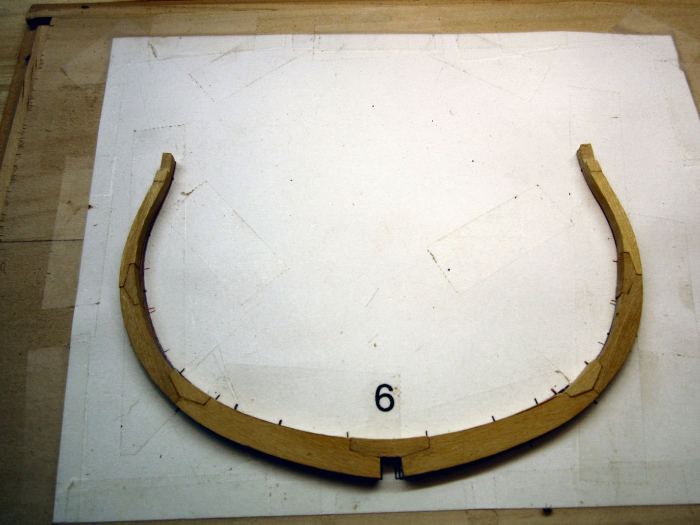
At this point I noticed that I had not sanded them enough and they had spread the frames a little (see the above picture). By that point, however, the glue had dried enough to prevent me removing them! I’ll have to break out my Jewelers Saw and cut through the center, which will hopefully remove enough so that the frames close up properly.
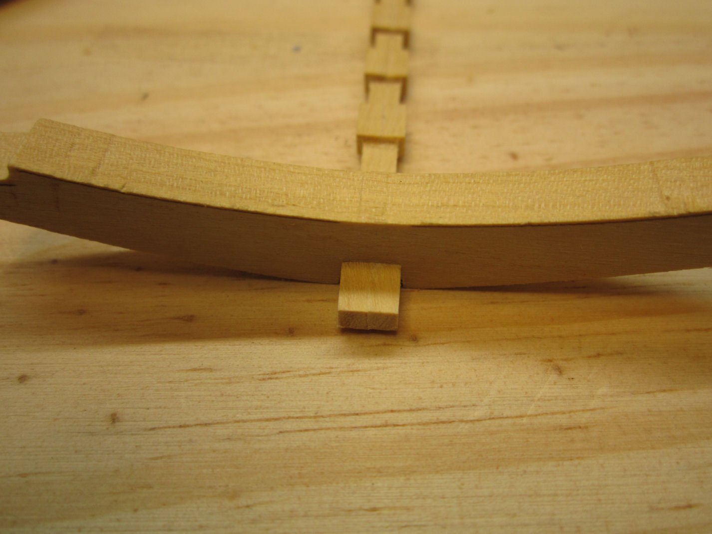
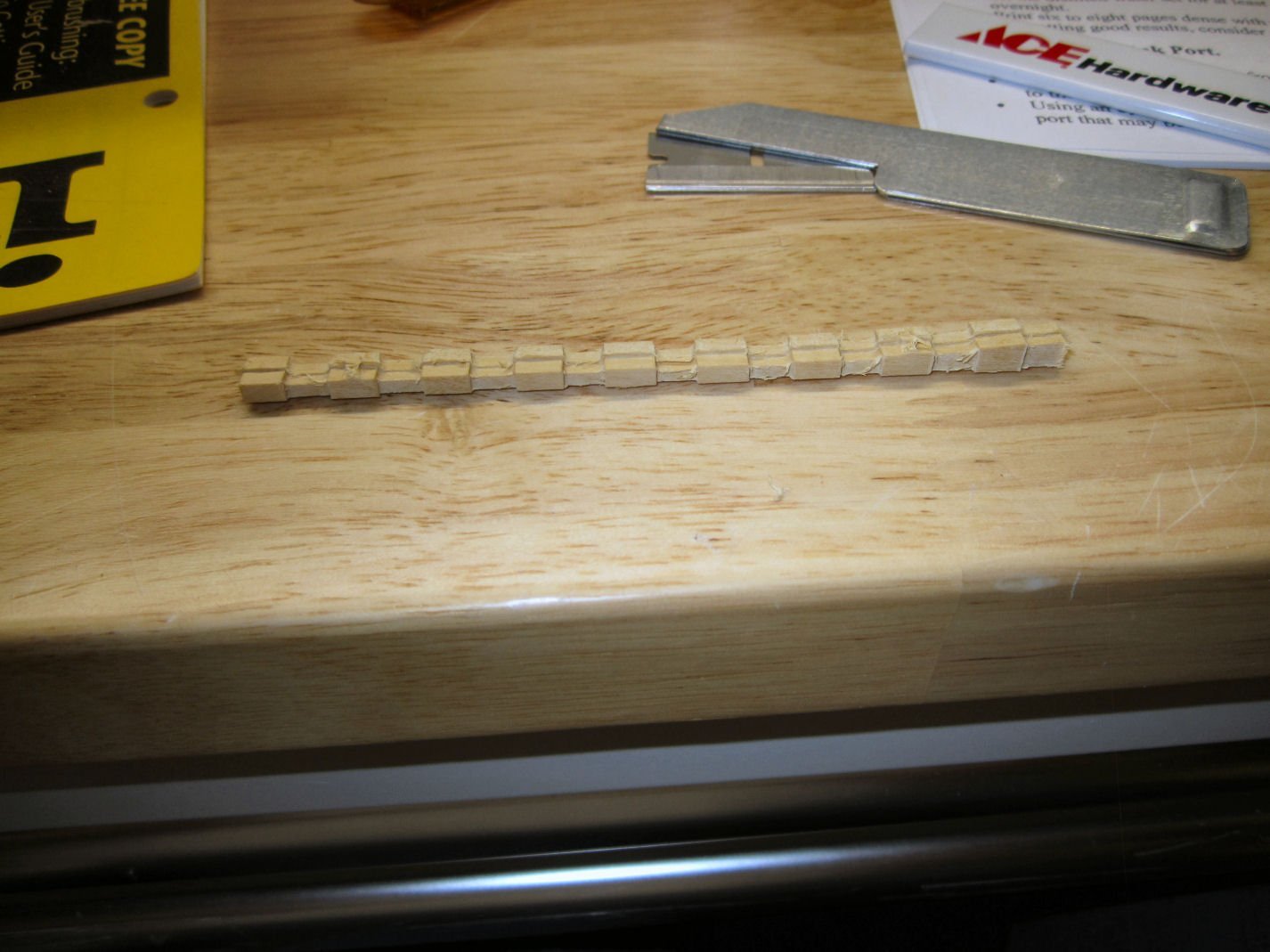
Meanwhile, I cut the chocks down to match the level of the respective frame members. The photograph shows one chock cut and sanded (right hand side), while I have just started on the second one. For this I used an X-Acto Number 2 blade, small files, and fingernail sanding sticks. After the chocks passed the fingernail test (a fingernail passed across the surface does not catch on any protrusions at the joints of the surfaces), I sanded along the grain to hide the marks made cutting out the piece.
After finishing the chocks on this side, I flipped the frame over and did the same to the ones on that side.
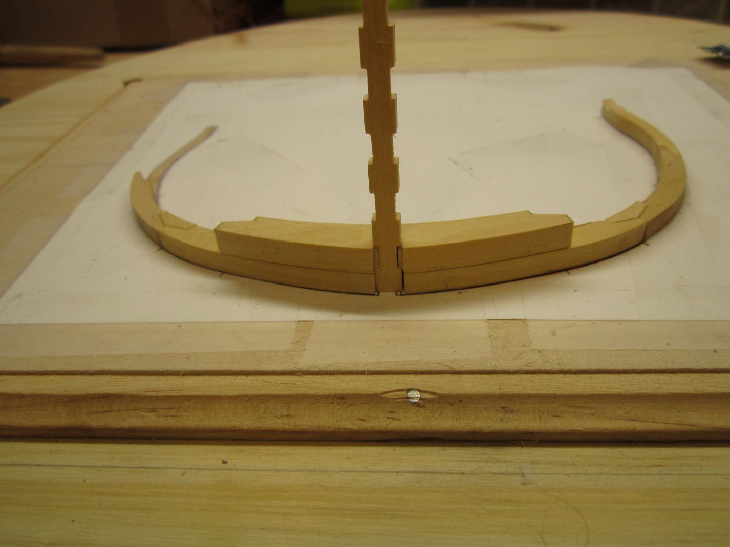
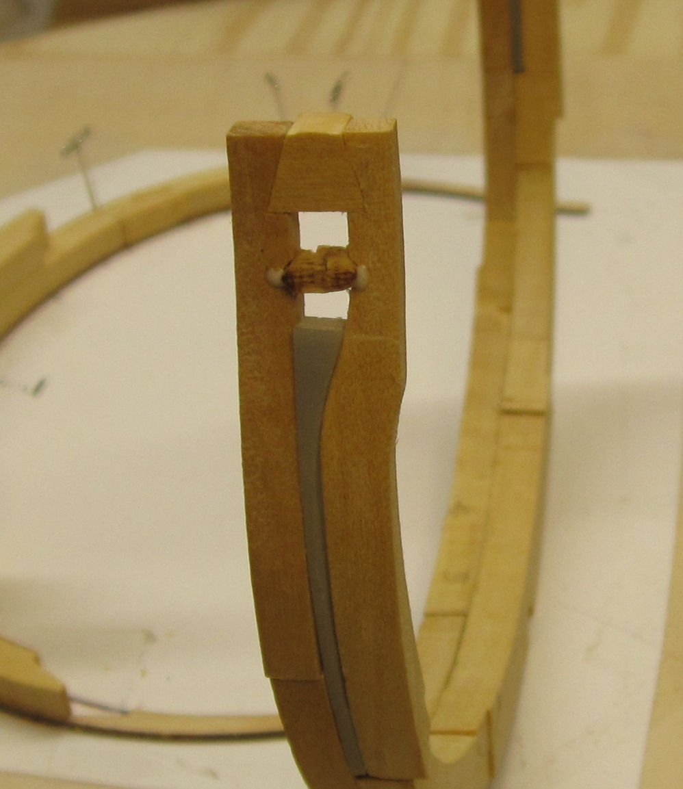
I then used the saw to split the plywood pieces, On one side the plywood fell out as I was completing the cut. I glued the two sections back together and reinserted them. In the picture below you can see them right after I got them back in.

I took a pair of flat surface needle nose pliers and used them to hold the two plywood sections into a flat alignment top and bottom (you can see that they are not aligned in the picture above).
Once the glue had dried I faired the ends of the plywood pieces and the blocks above them down even with the frame surfaces. I also filed the top and bottoms of the plywood inserts to insure that those surfaces were lined up correctly.
I managed to pop one of the other joints in the frame while doing this, but in the end, I finally finished this frame!
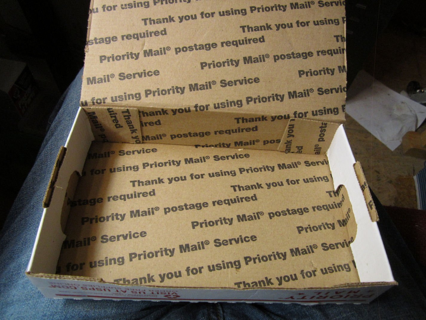
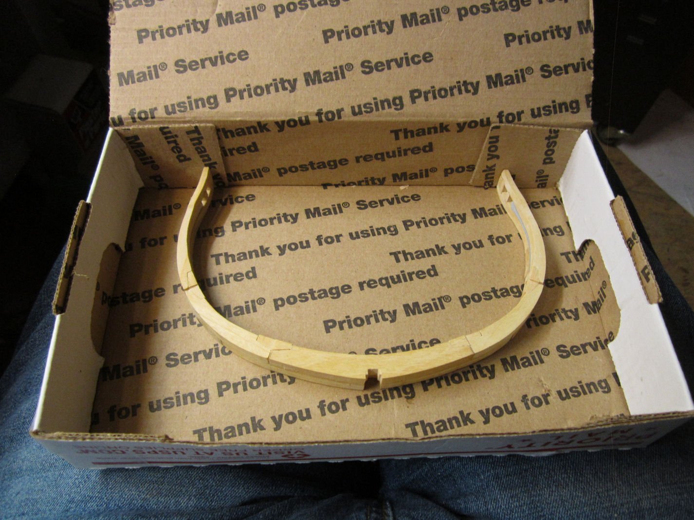
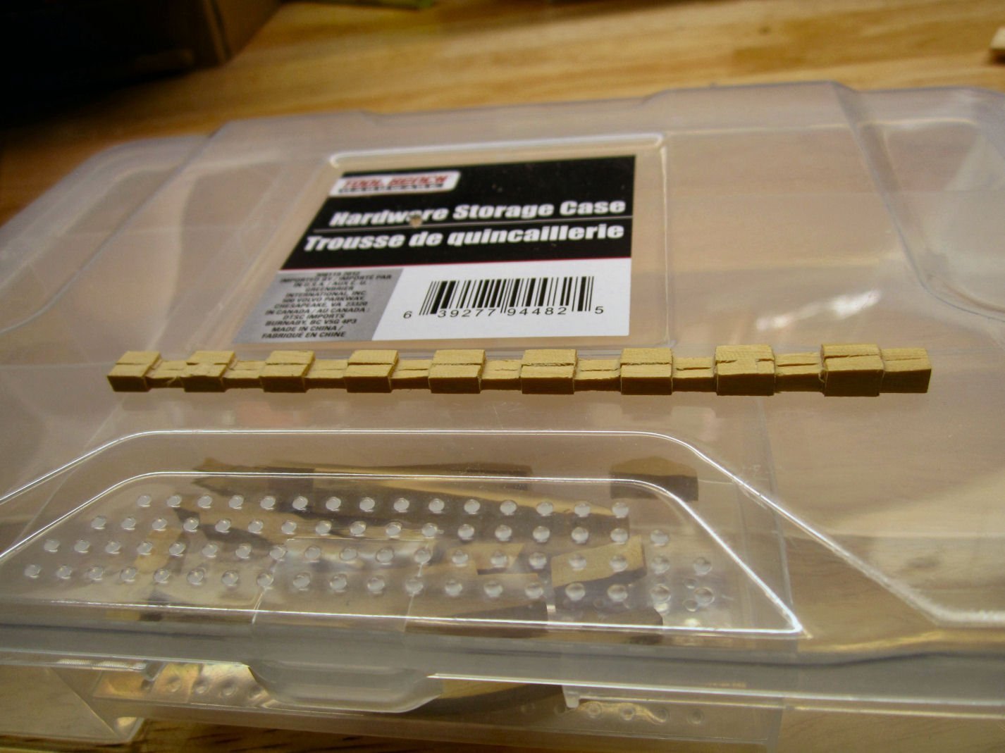
Next I started to look around for something to store the frames in, as I finished them. In the end I found a simple, cheap, way to do this. I had a beat up one of the small Post Office Flat Rate Boxes laying around and when I folded it up, it was an ideal size.
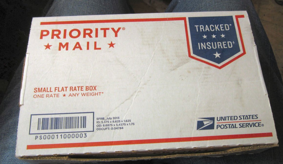
The box is designed to be held together, once folded up, when the tab on the top is glued to the front of the box. As I was going the not glue the top down, I glued the corner tabs in place then folded the side ears down and glued them also. After cutting the ears off the sides of the top, I had a nice frame holder! It is large enough to hold two frames in each layer, if the second frame is set in upside down so that the bottom of the frame spans over one tip of the first. It looks to be deep enough for three layers (6 frames total) of frames per box.
At this point, in time, I have also finished Frame 7, and will detail that in the next part. Before starting on the next two frames (7 & 8), there are corrections to the instructions needed, so stay tuned, (or go to John H’s review of this kit, where he details the corrections)!
- dvm27, Beef Wellington, coxswain and 9 others
-
12
-
-
Welcome!
- Keith Black, Dave_E and mtaylor
-
3
-
-
-
PART 17
With the temporary case built, I turned to the bow sprit and masts.
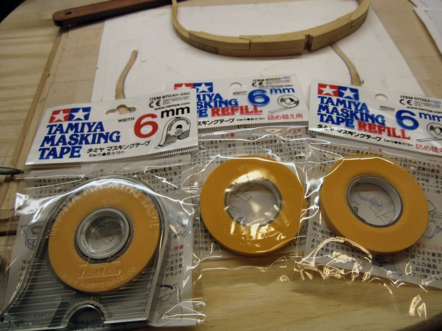
First I attempted to hand paint the metal work on these, but failed miserably. My hands are not up to such fine details. So, I went to mask them, only to find that my tape had disappeared during the renovations. I bought some off Amazon, and resumed when they arrived.
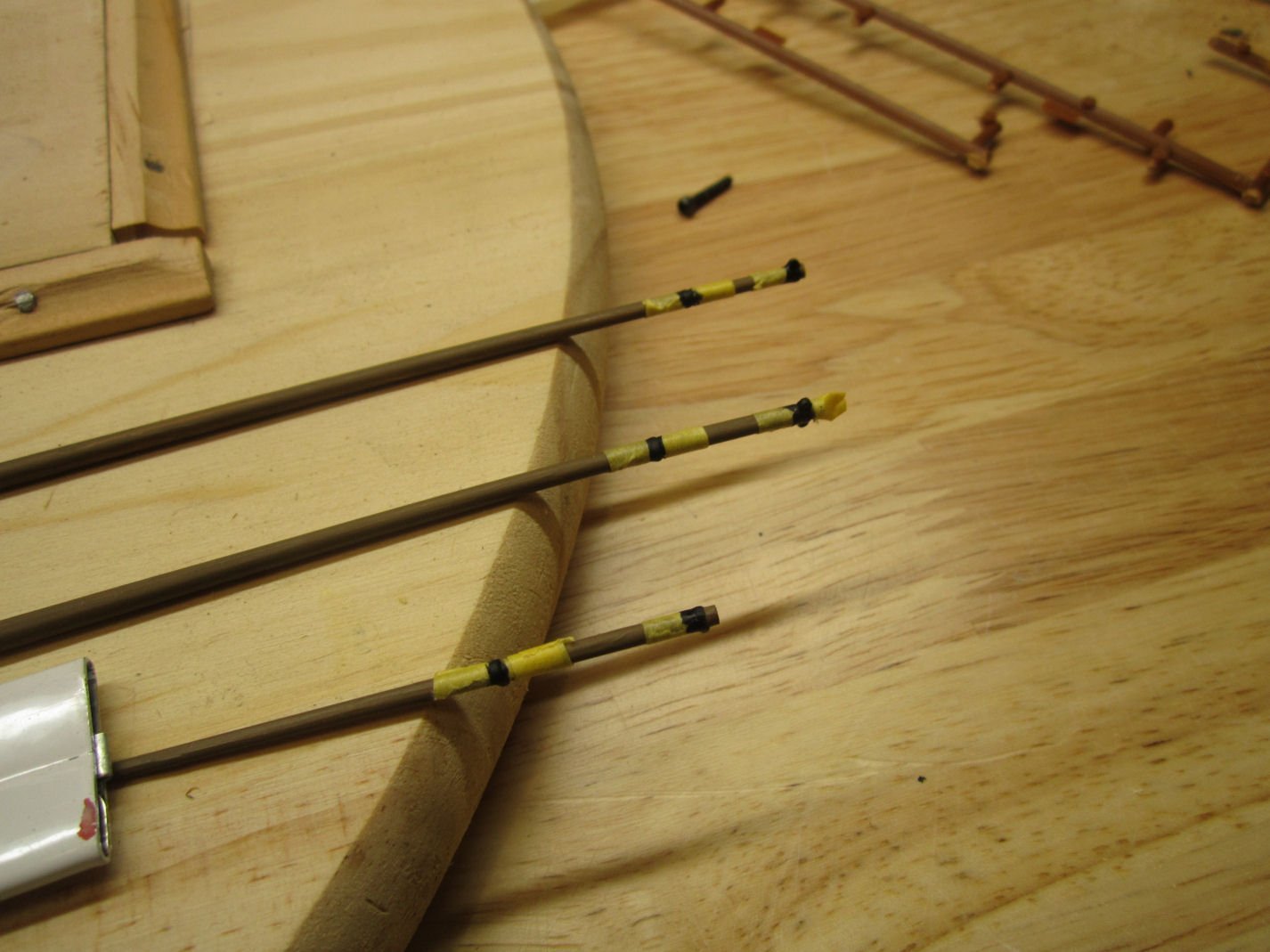
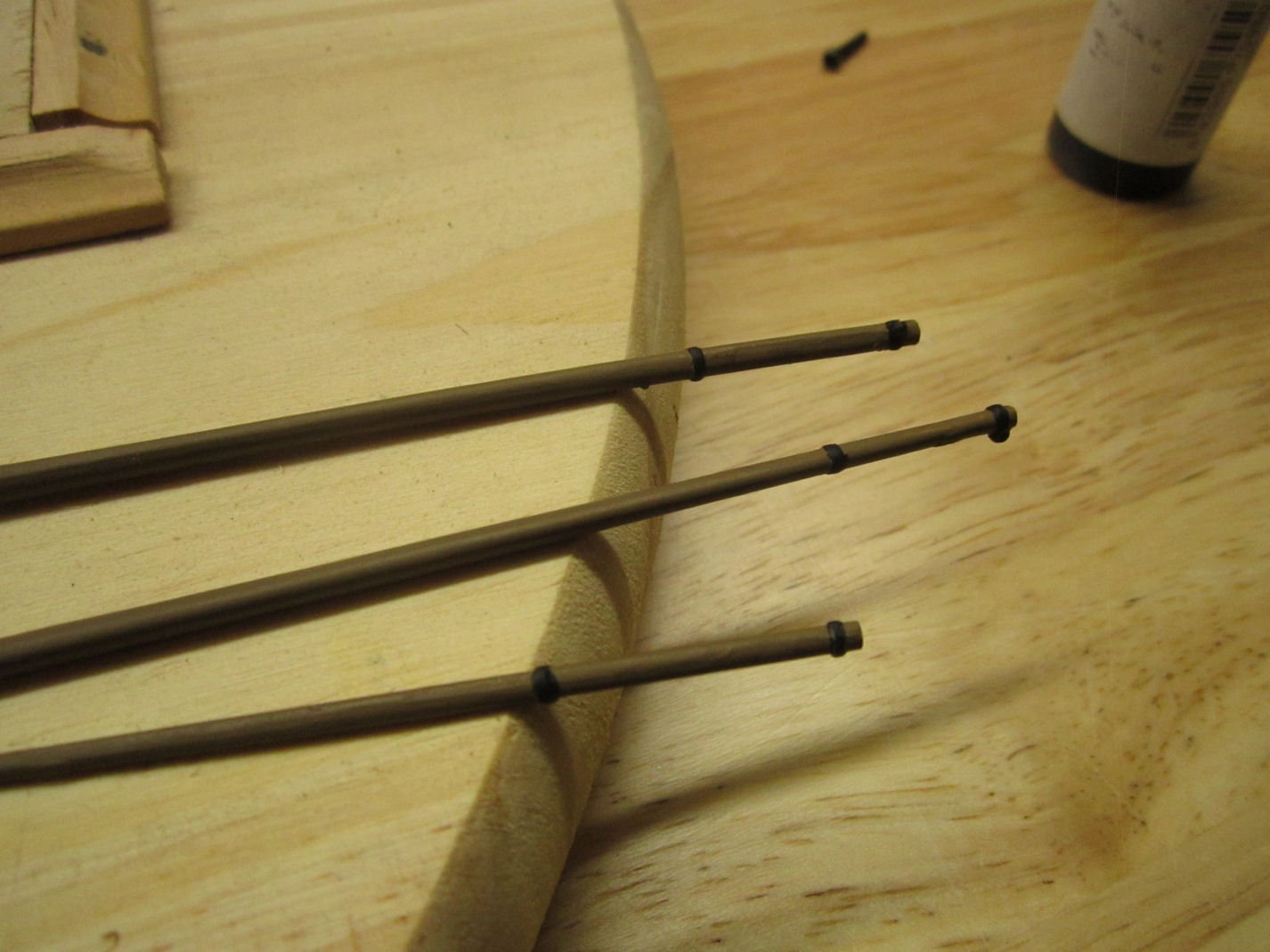
After the black paint had set I repainted most of the wooden areas of the spares, as I found some thin spots.
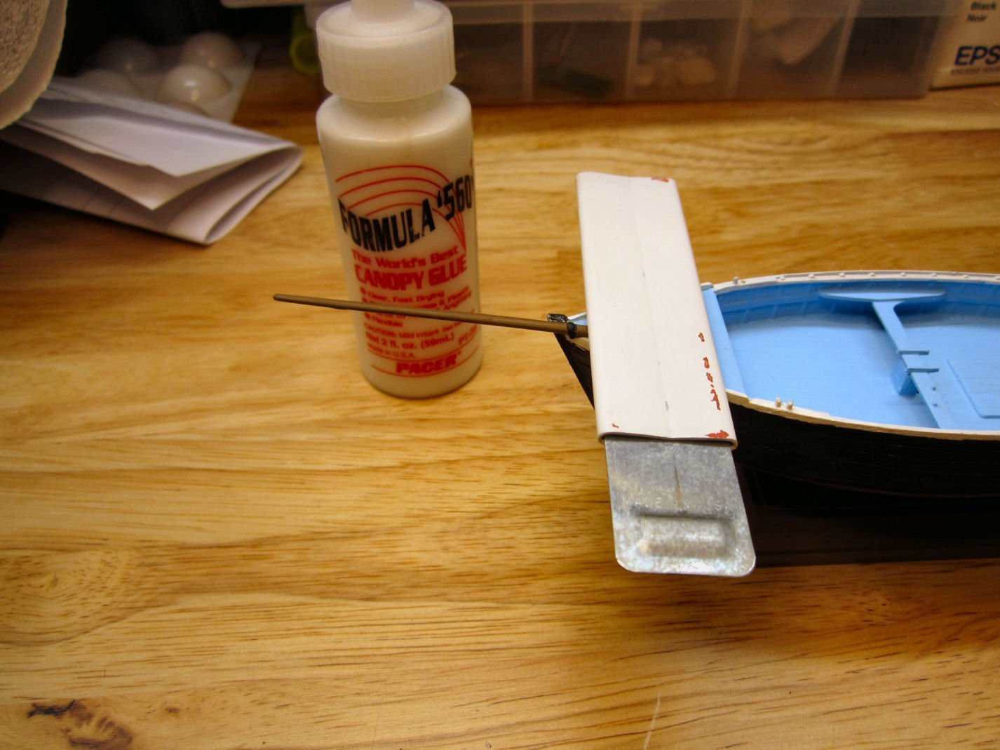
Because the parts were already painted, and of contrasting colors, I attached them with “Canopy Glue” so as not to damage the existing paint, like plastic glue would. “Canopy Glue” is a refined type PVA wood glue that dries clear, and was originally developed for gluing canopies and other clear parts onto plastic models. Regular plastic glues and CA will often etch the clear parts, causing them to fog. I think it will be strong enough for the spars on this small model, though I’m not sure about larger assemblies.
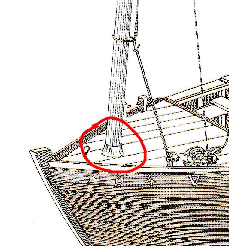
I started with the bow sprit. I carefully scrapped the mating surfaces where the end of the sprit contacts the deck, but left the paint on where it touches the railing. I placed a weight on the parts and let it set overnight. The next morning I had to add a little more glue to the railing area, as I had skimped too much here.
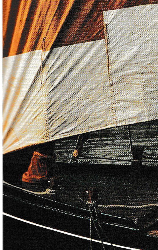
On the real boats the sprit slides in and out through the two metal rings, and thus can be removed if the jib is not being used.
The fore mast was a little too thick where it goes through the deck hole, so I scrapped and sanded, that section. I could not drill the hole in the deck larger, as the bow sprit sits right at the edge of the hole. After checking the instructions, I installed the mast with the cleat toward the port side. I glued it at the base and the deck. After it was in, I added a little more Canopy Glue around the mast base to strengthen the bond, and simulated the leather cover used to seal this area from water entry into the fore cabin.
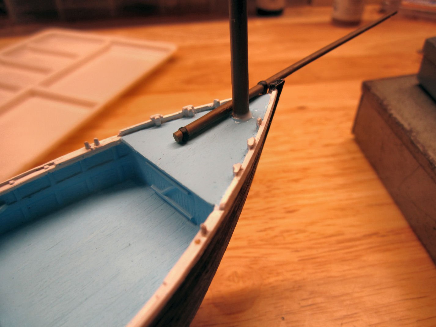
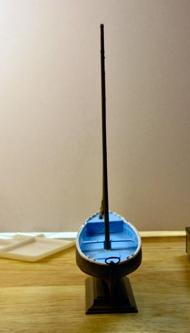
The main mast was also too large for the deck hole, but with more room around it to work with, I drilled it out in stages, using some small number drills I have (larger number drills than the standard #61 to #80 ones). This mast was installed with the cleat to the aft of the mast.I also put the reinforcing glue around this mast for the mast leather.
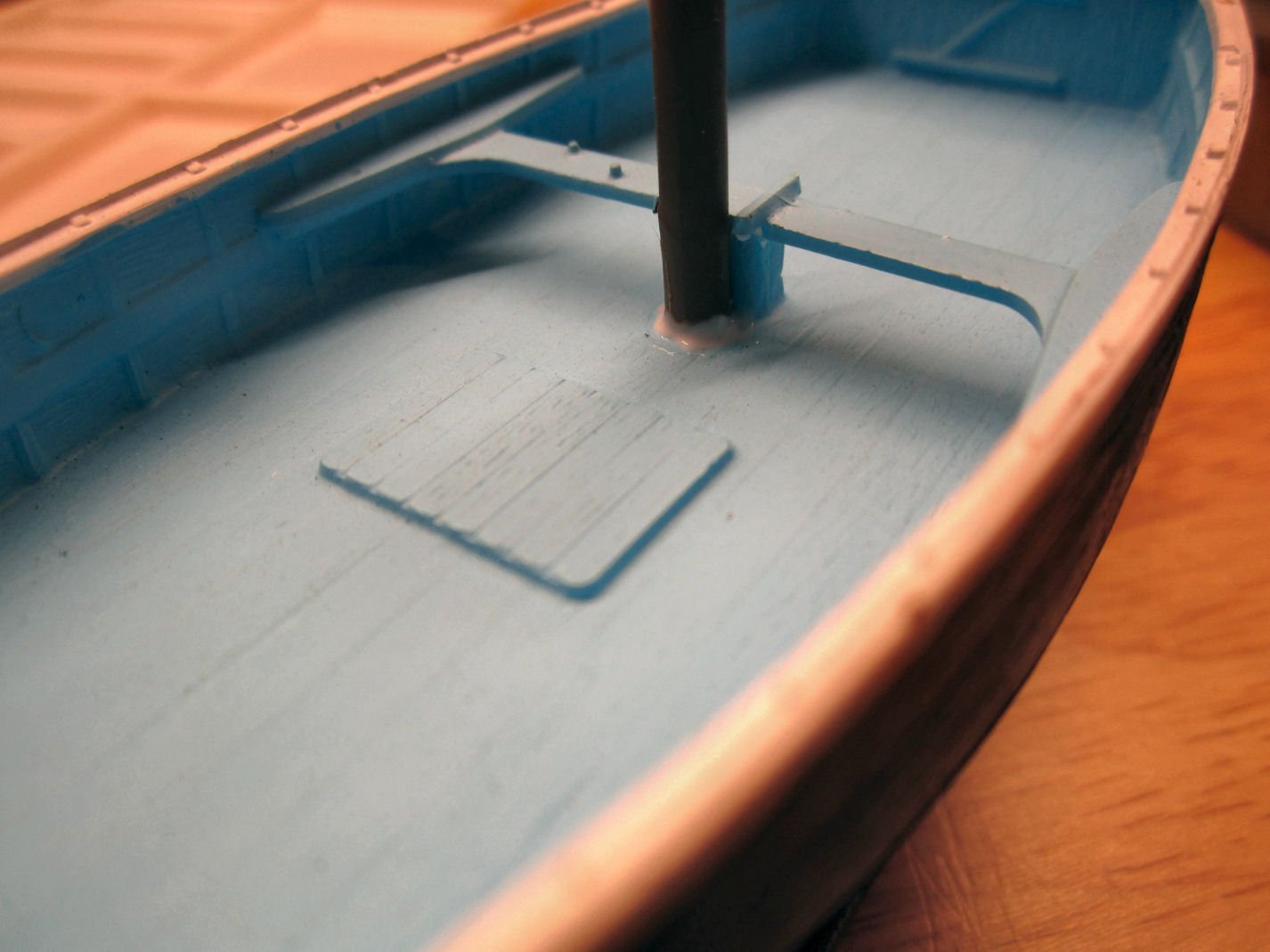
I set the boat on the workbench and played with the masts until they were perpendicular to the deck and in line with each other, and left it to dry overnight.
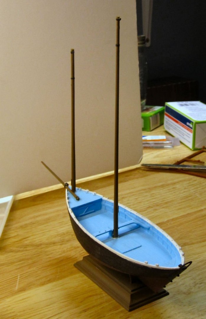
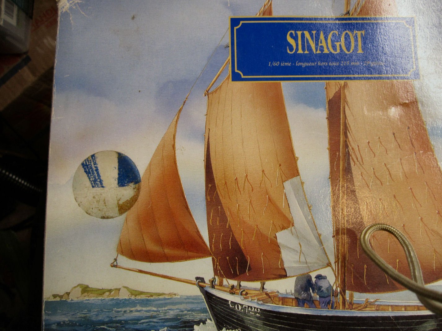
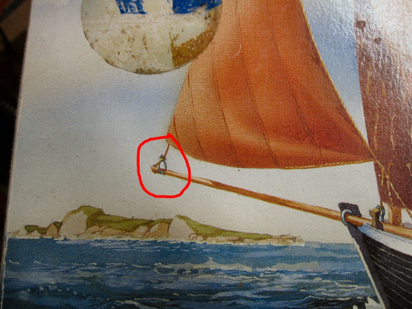
This will be it for a couple weeks. The next step is to make silkspan sails. I’ve never done this before, so some failures are expected. Once I’ve got the sails made, I will paint the mast to deck covers the same color as the sails. I also have to fabricate another of the unique hoist rings, and perhaps the ring shown at the tip of the sprit, on the box art. There was a recent discussion about similar ones used on larger ships. It is called a traveler. When the jib in use it sits at the outer end of the Sprit, and is pulled in when the jib is to be stowed, pulling it down along the bow sprit. While you would not leave the jib permanently stowed this way, it does allow you to then re-fly the sail, if needed shortly. This also makes it so you don’t need to go out to the end of the bow sprit every time. The jib on the Sinagots is not attached to the forestay, but suspended from its own halyard.
- yvesvidal, wefalck and Haliburton
-
3
-
-
-
Thank you for posting this tread! I'm sure what solutions you find will help the rest of us, that plan to buy one of these printers in the future.
- Egilman, Canute, Old Collingwood and 2 others
-
5
-
-
-
Part 009
Next I had to clean out the inside corners of the upper piece for the slots for the false keel, keel, and chocks, to remove the rounded corners left by the milling bit.
After further cleaning up the false keel, I used it and the keel to check my progress on cutting out the corners.
Next I used the false keel as a jig to align the upper and lower frame slots, and glued the upper section in place, then removed the false keel and placed weights on the upper section and along the exposed lower half to keep everything level while the glue dried.
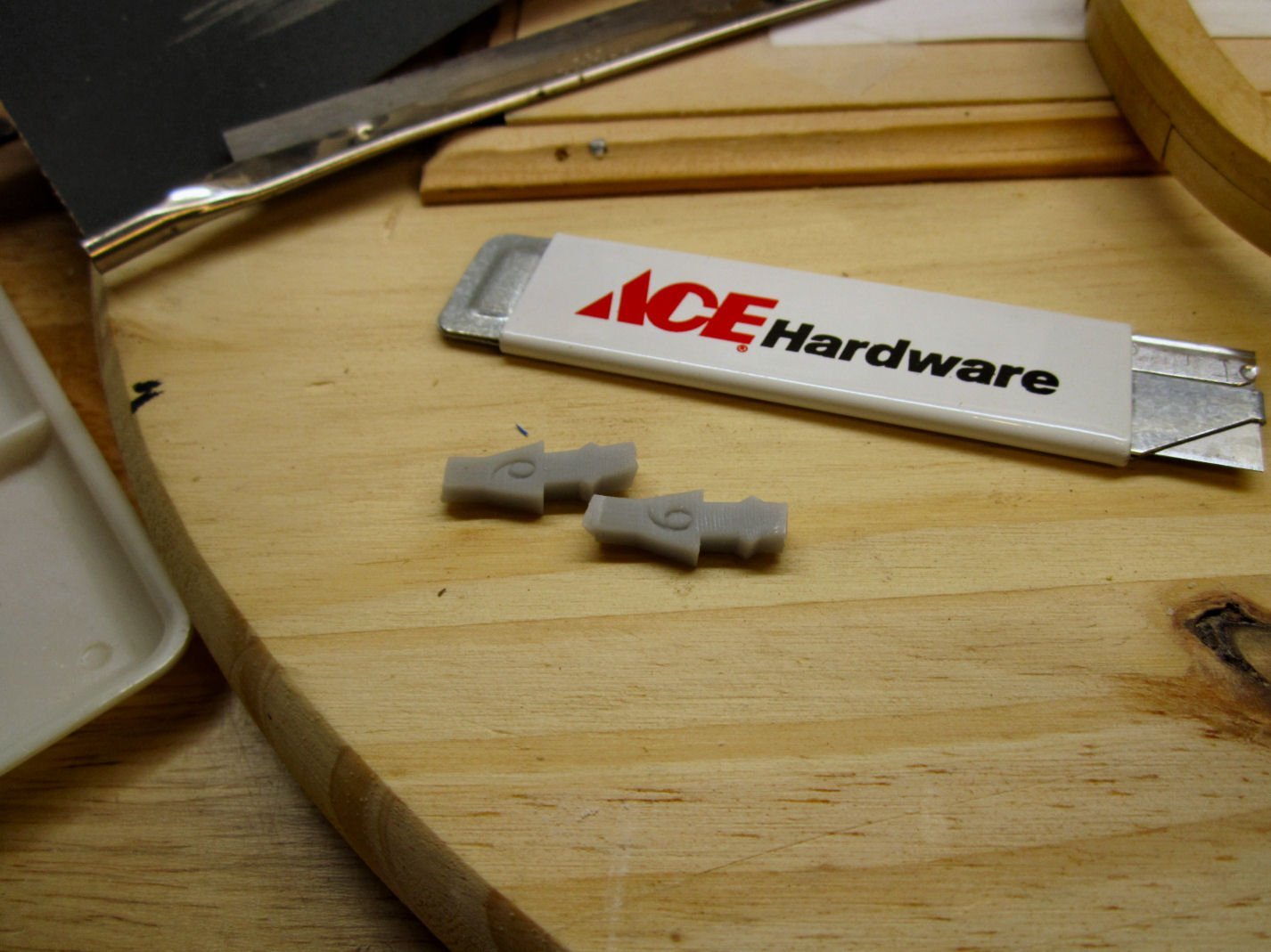
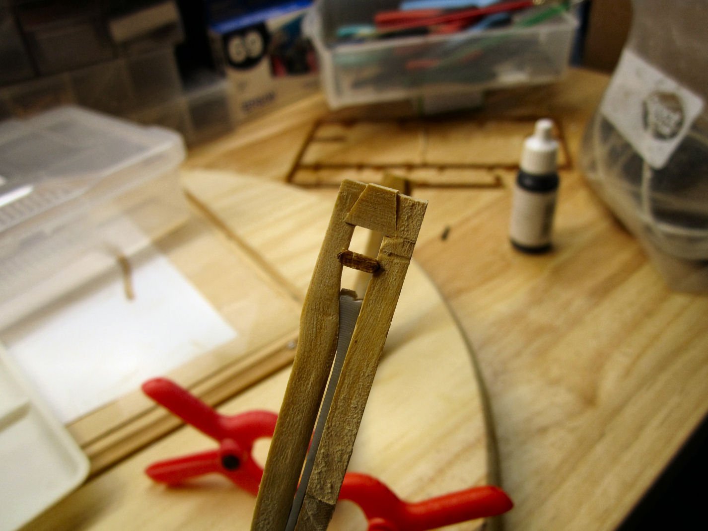
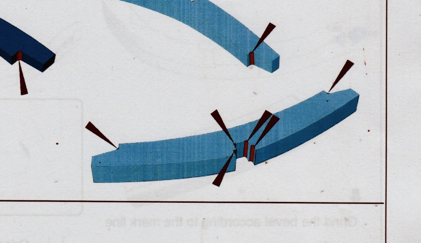
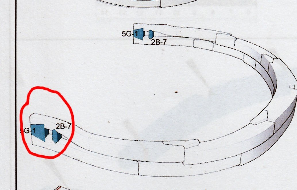
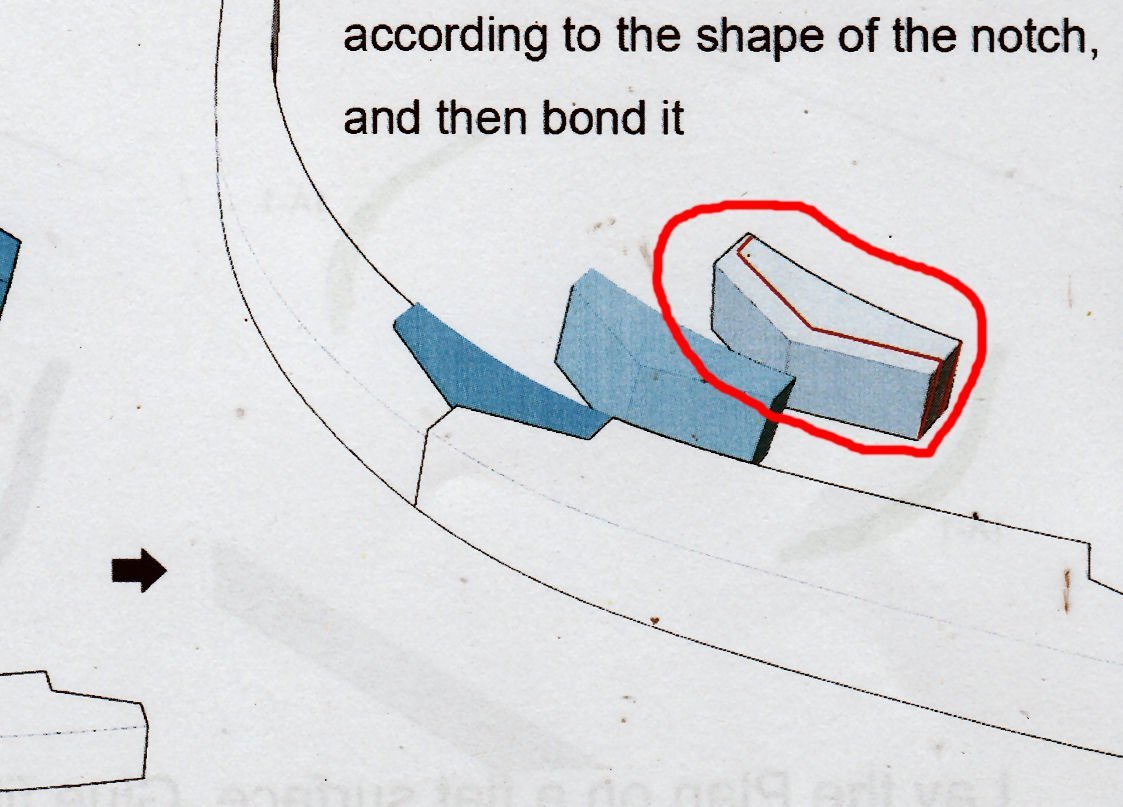
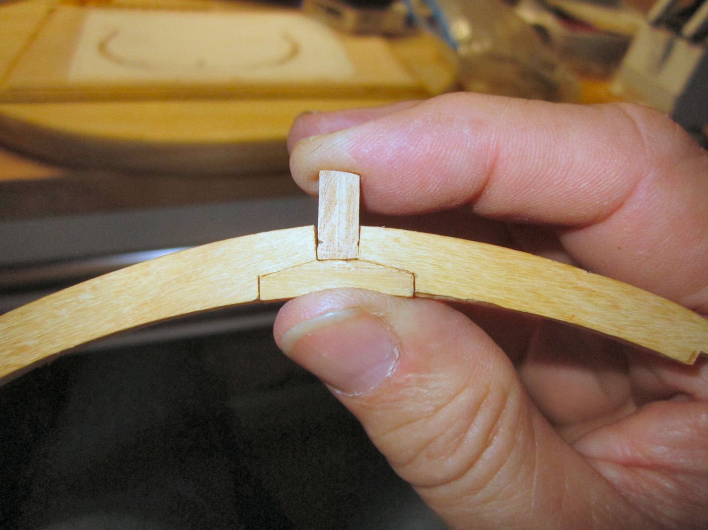
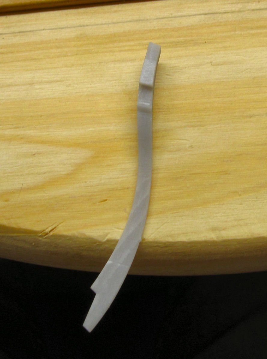
Next came a step that should have been in the instructions, before the frame assembly. There is a temporary resin fill piece between the upper and lower halves of the frame, that positions the upper tips of the frame pieces, away from each other. After the frame is glued, two small pieces of wood span areas of this gap, and form part of the finished frame. The only reference to this is the graphic of assembling the upper half, were it is shown in place between the frame sections.
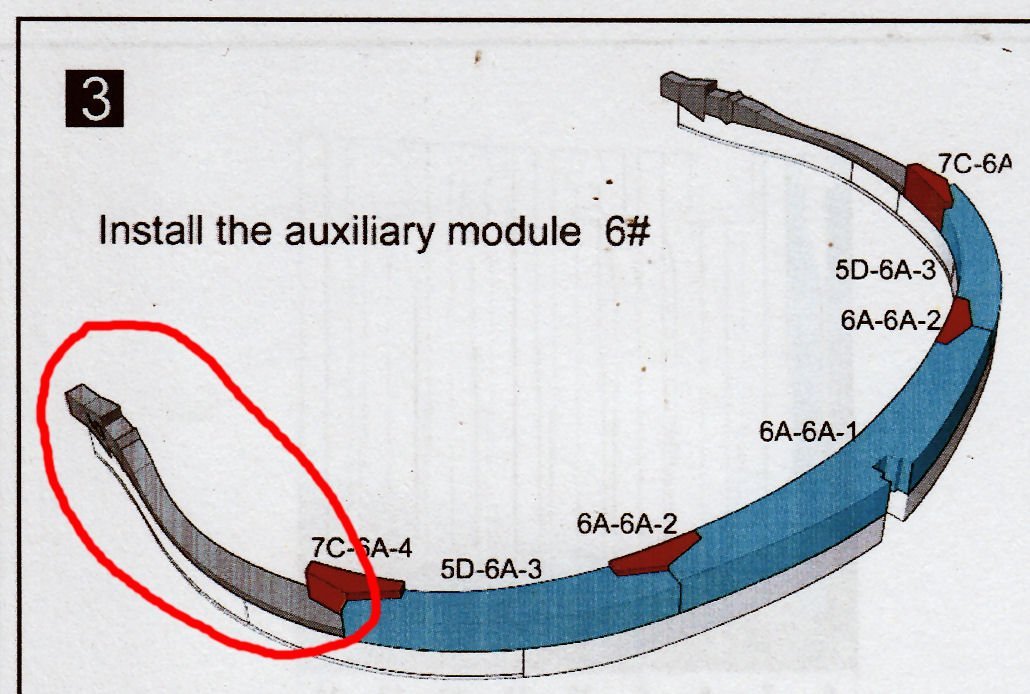
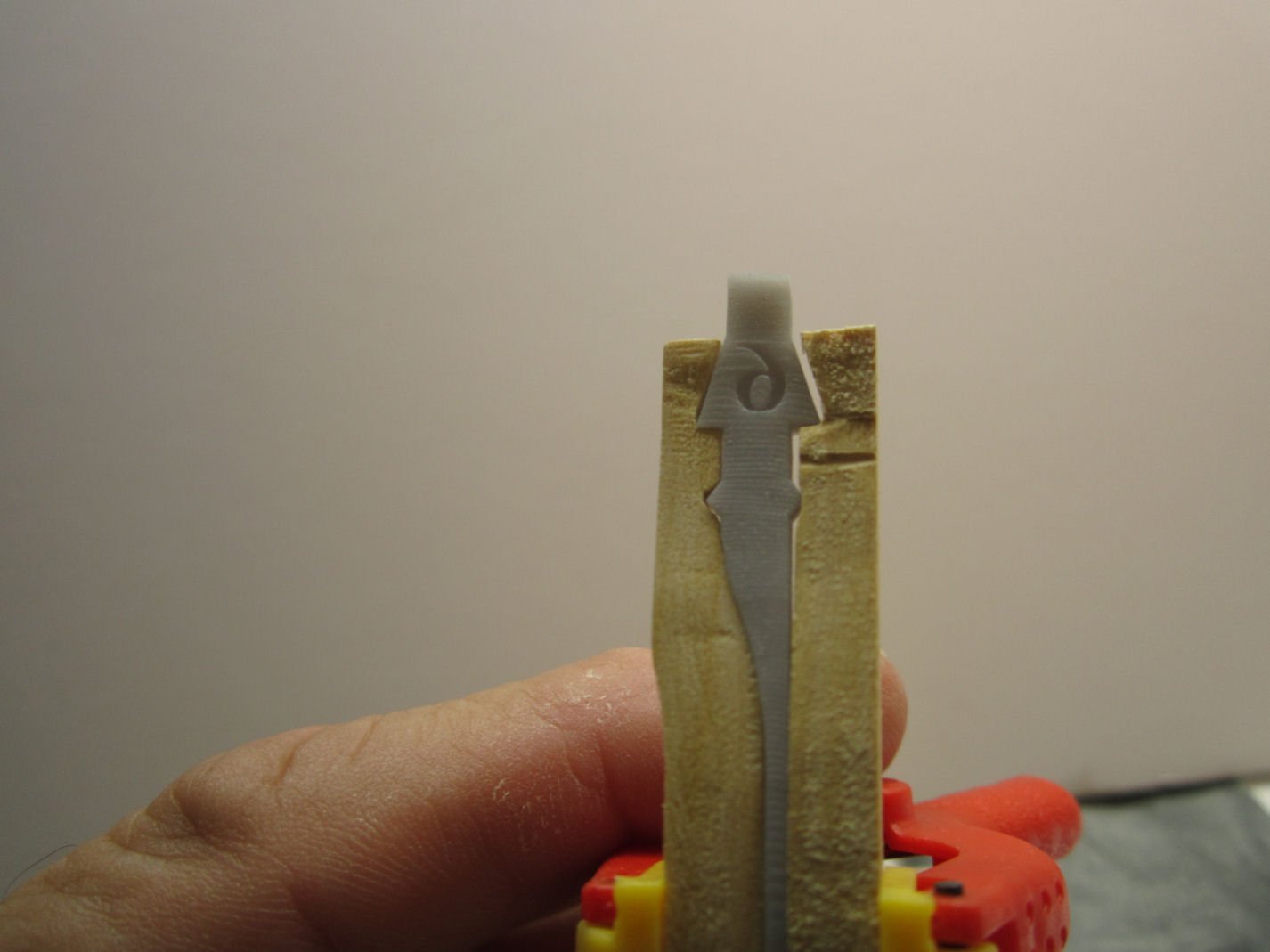
This shows the two pieces that will be installed when the inserts are removed.
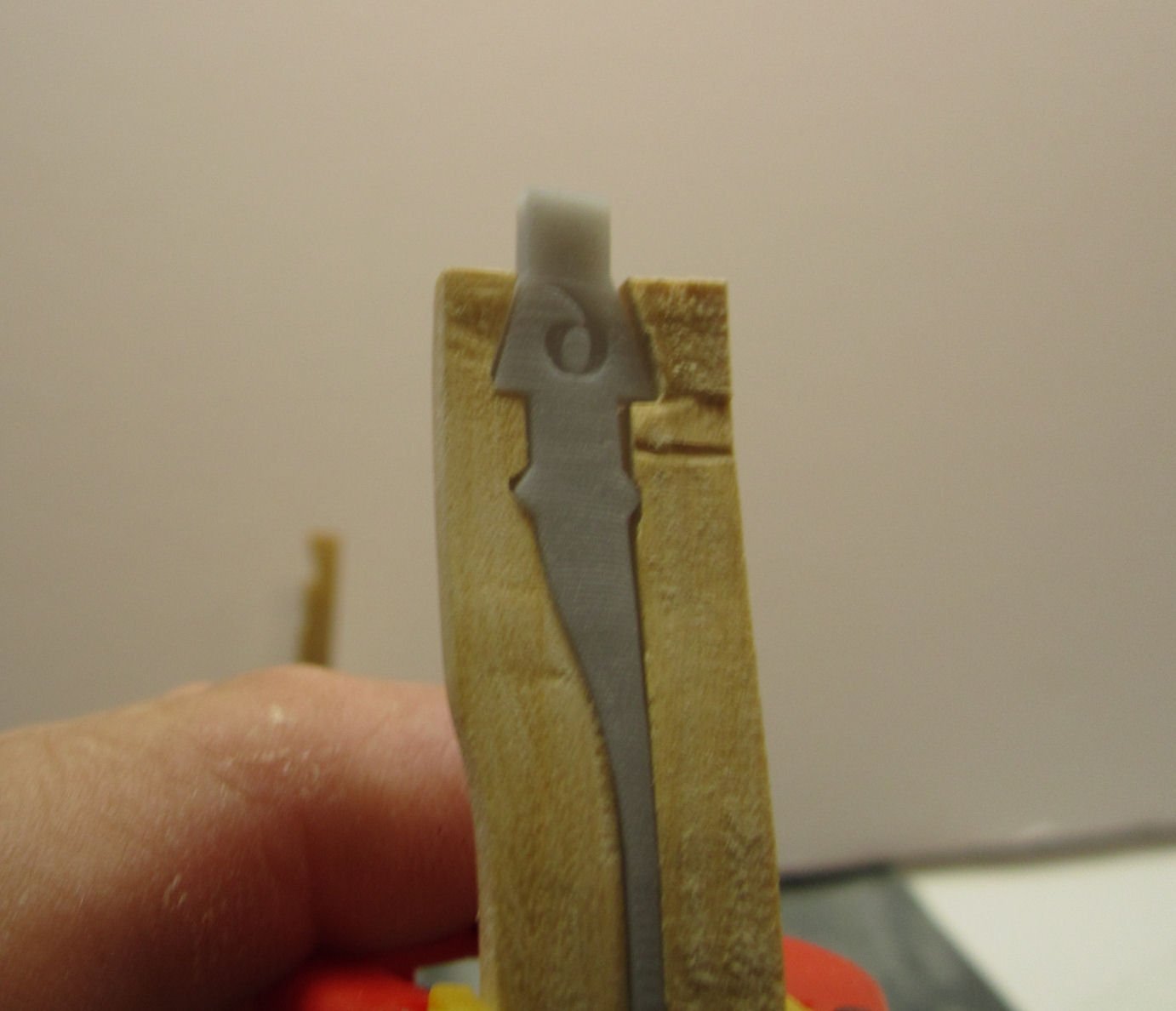
The entire upper tip piece will stand proud, of the lower frame half, held in place only by the chock and the two inserts, once the frame is finished. After I install the two wooden support pieces, I’ll trim the head off the insert, and reinstall the tail piece, to support the gap, until I reach a point where it is no longer needed.
The problem, is that both the upper and lower tip pieces have to be fitted to the resin piece, just like the chocks and keel parts. With the lower half assembled this proved awkward.
One thing to be aware of, is that the groves are angled, not straight across the frame section. Yes, I didn’t notice this on the first two pieces. The resin piece required minor cleanup to remove some small vent nubs along the flat tail piece.
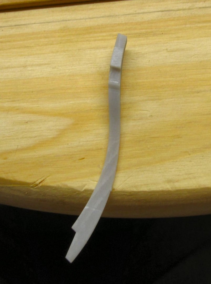
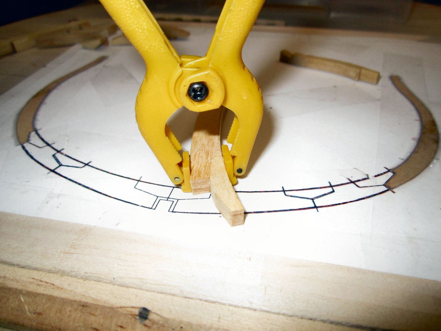
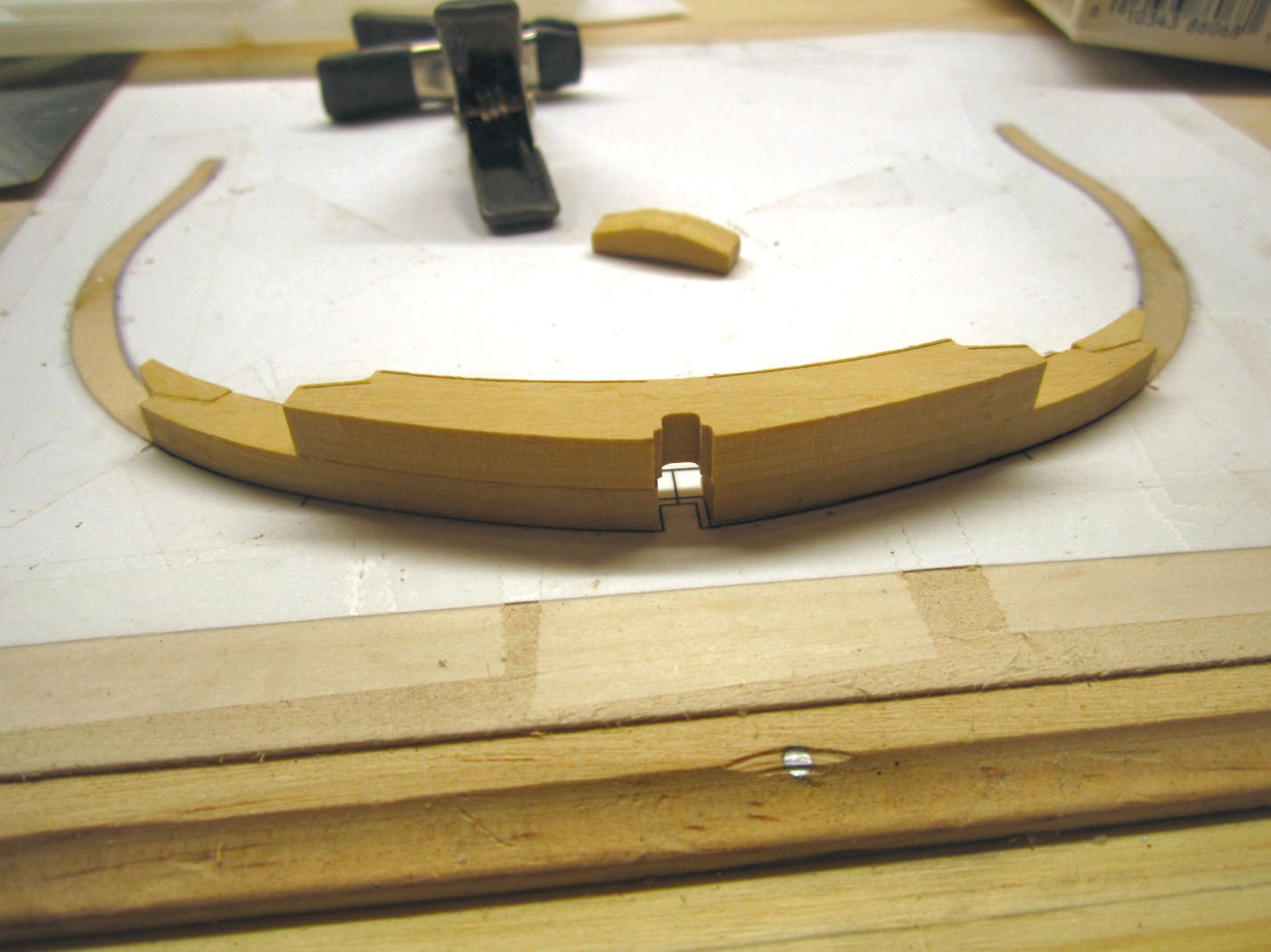
This is a picture of one side cut to fit the insert, and the other before I started.
Here is both sides fitted.
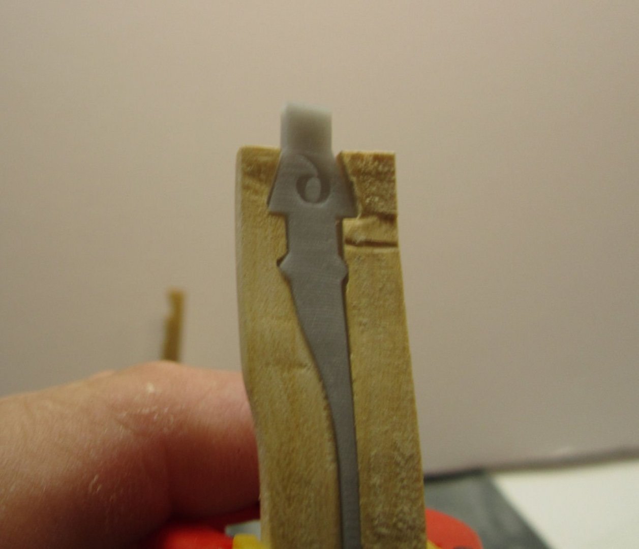

Notice that the lower frame half tip (the upper one in this shot) “re-kitted” itself during the process. The same thing happened on the other side.
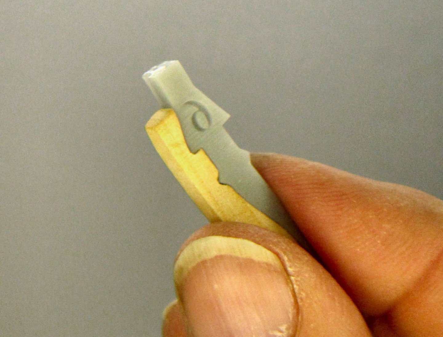
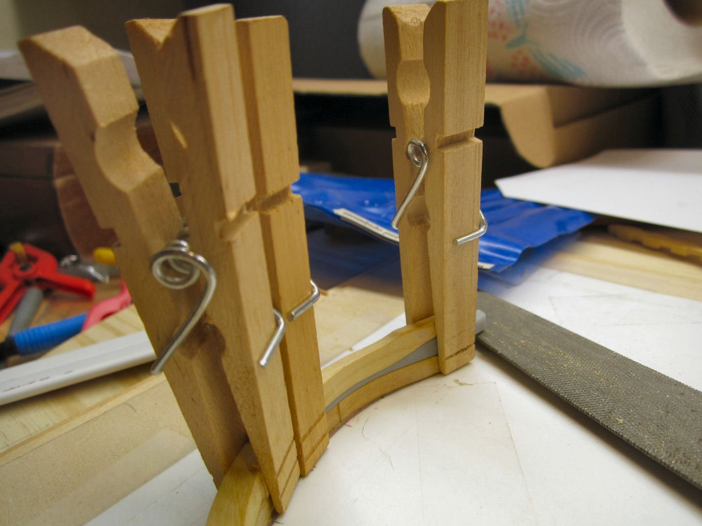
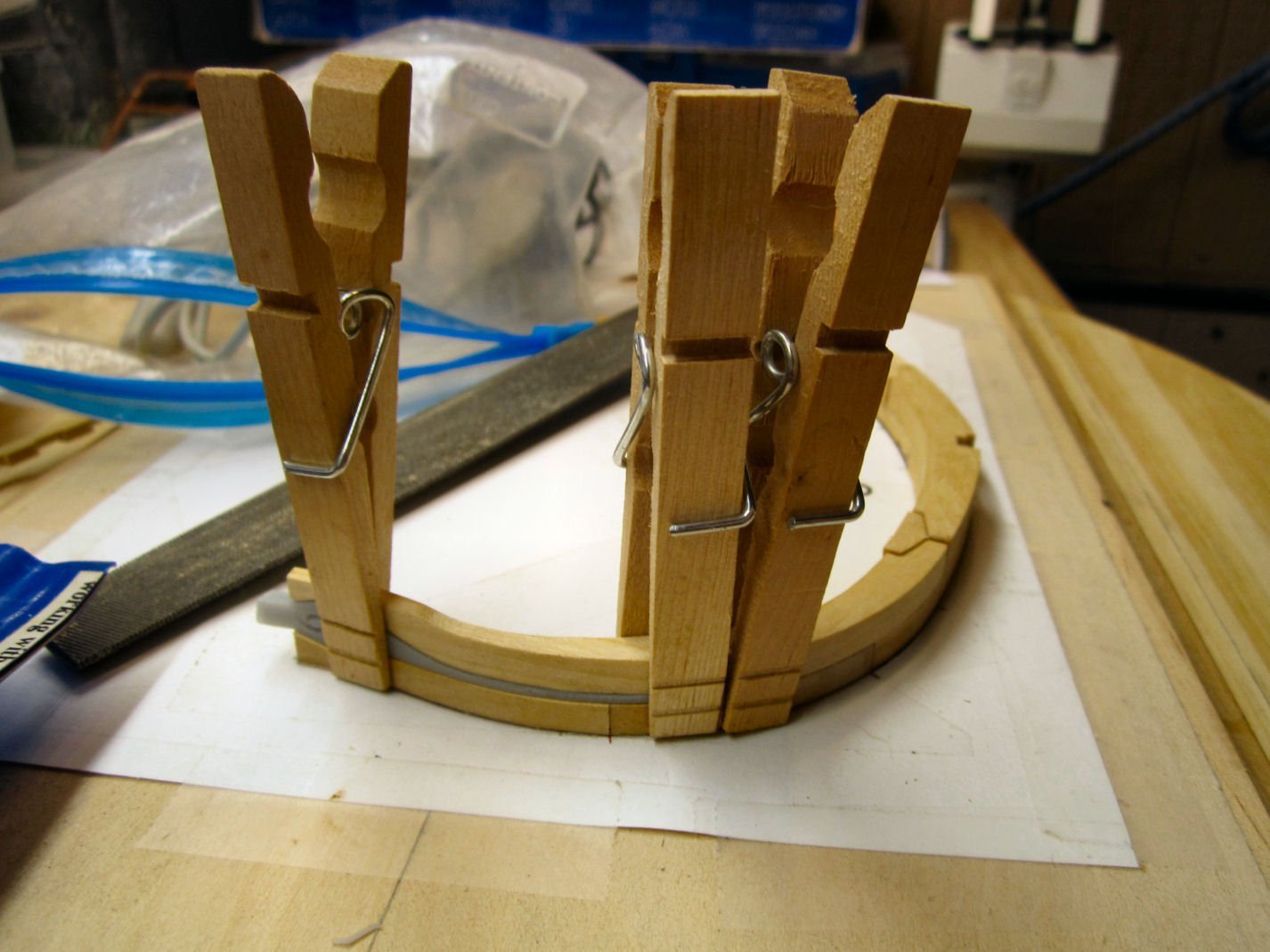
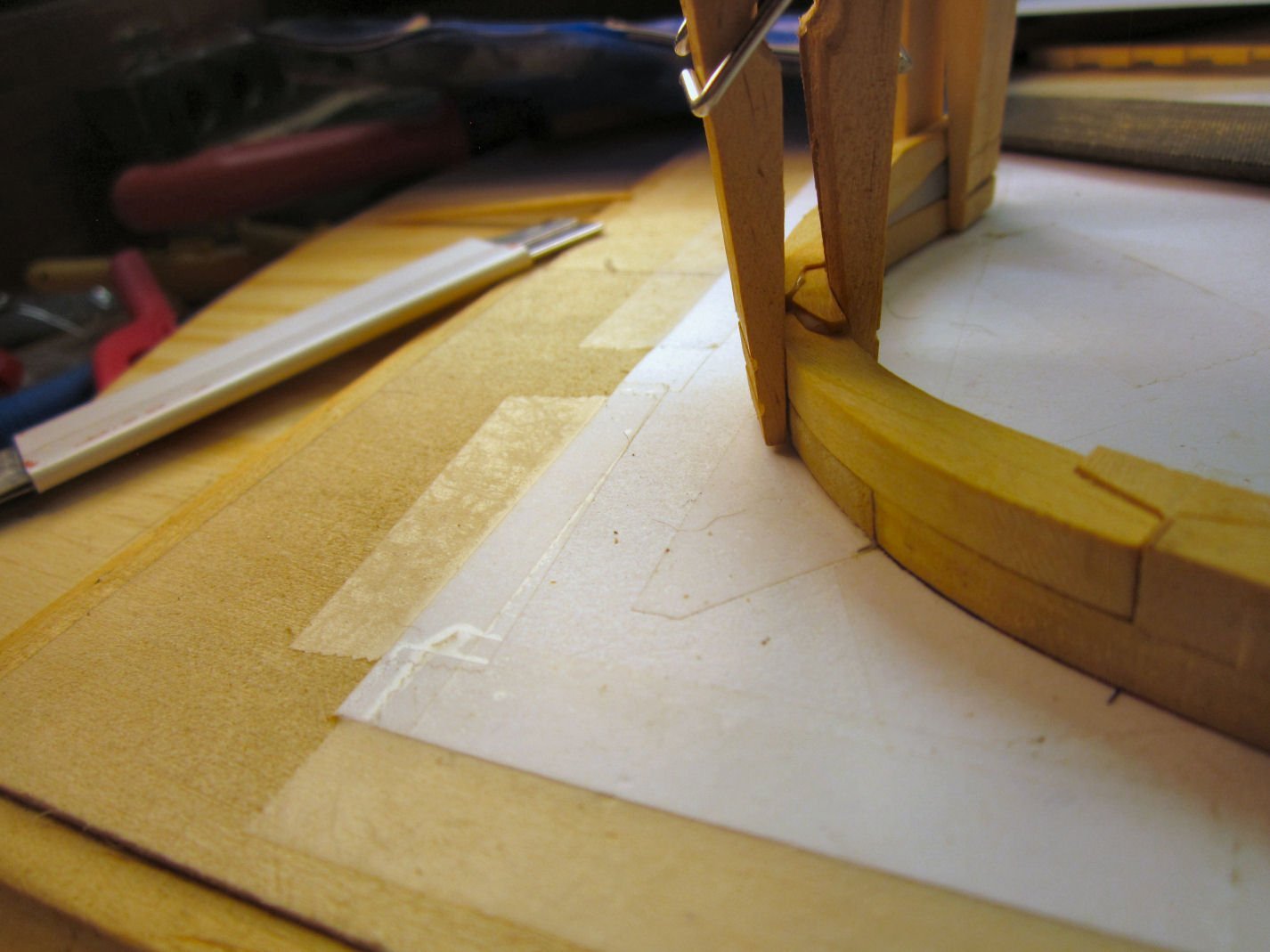
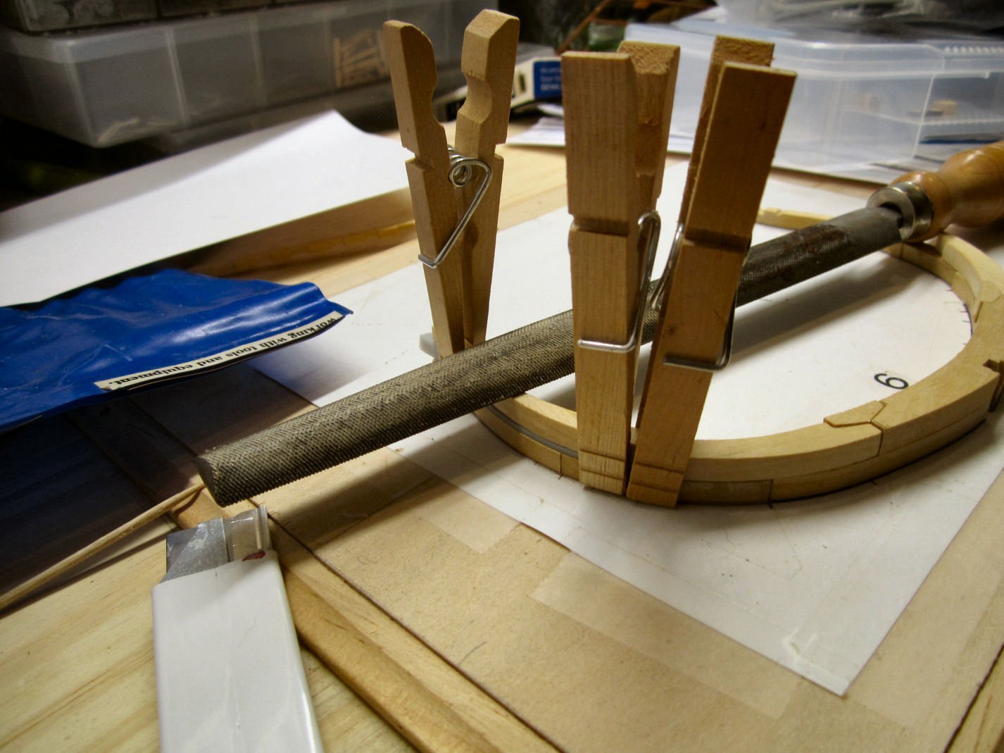
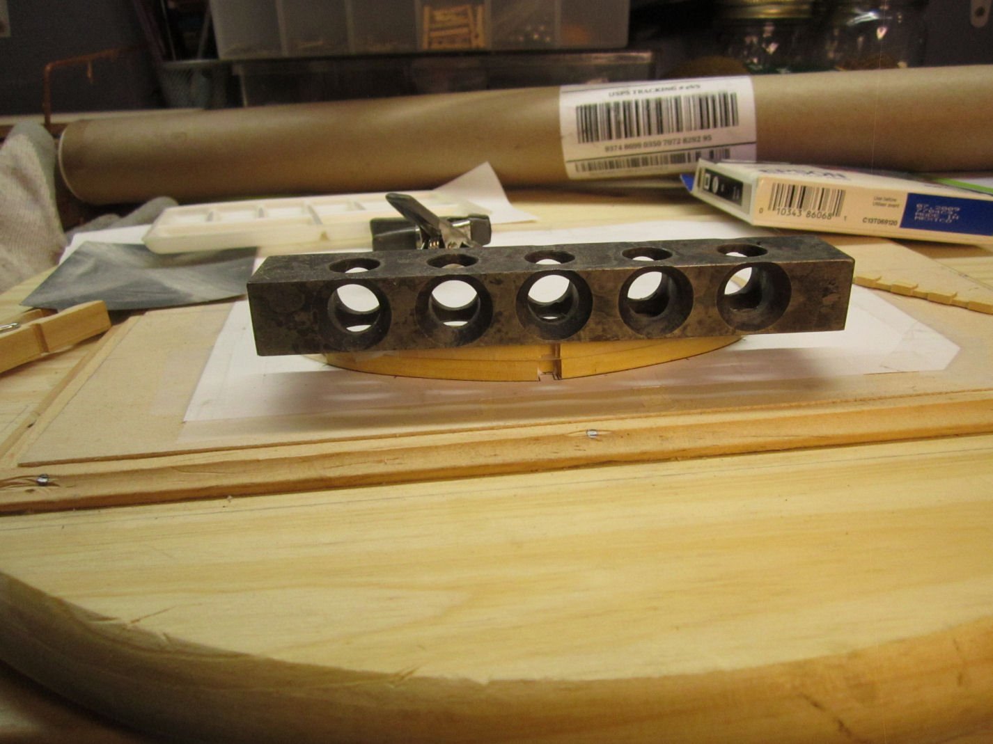
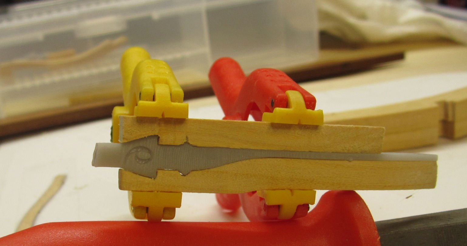
So, after fitting the parts, I reattached the two lower frame pieces, and, after the glue dried, proceeded to glue one of the upper pieces in place. I shortened the tail piece of the resin spacer a little, to make sure that it was not hitting the adjacent frame section. I found that modified clothes pins had just the right spacing to clamp the parts parallel. I reversed the spring so that the handle ends were the side closed by the spring pressure (see the photos). I used a clamp on either side of the chock, and at the top of the frame to hold the tips in line. I used a file to add weight to hold the tips tight to the insert.
This method does not normally work on a single chock holding two frame sections as the pressure tends to push the parts away from each other. For this use though, everything is locked in place by the insert and the previously glued sections, and the clamp ends are spaced by the lower frame surfaces.
Yes, the third photograph shows a nice lump of excess glue at the chock, but that end of the chock will be filed down to match the frame section, which is thinner than the mating end of the tip piece. If you look at the joint to the right in that picture, you will see that the same thing will have to be done to one side of that chock, also.
The forum software only allows a maximum of 16 pictures per post, so I will continue when I get a bit further along is completing this frame.
-
Welcome!
- Keith Black and mtaylor
-
2
-
Part 008, or “How to continue to do it wrong!”
During the build, I will continue to show mistakes, why I made them, and (Hopefully) how I fixed them. This is my first POF build, and basically my first wood sailing ship kit, though I have built HO scale wood buildings and wood RC warships. By showing my mistakes, I may help others avoid them. “Good judgement comes from experience, experience comes from bad judgement. "
In retrospect, I should have started with one of the inside frames, where mistakes could have been more easily hidden.
As I mentioned before, Frame 6 would not fit back between the shims when I tried to put it back into place. After getting everything un-glued, I rebuilt the lower section of the frame first, so far so good. Then, I said to myself, “Self, you know this frame has to fit onto the keel, doesn’t it?”. Self replied, “You’re right, better try that!"
So I found the two pieces for the keel, the keel, and false keel. The first thing I found was that both pieces had been machined incorrectly!!
As you can see above, the blank apparently shifted a little when they turned it over to mill the back, and the upper and lower surfaces came out misaligned. Not by much, but after cleanup both the parts were too short by twice the difference in misalignment (had to correct both top and bottom). At least the relative depth of the lands on the false keel are correct. So, I thought, “I can just add a shim between the keel and false keel, to make up the difference.” Looking at the keel. I then discovered that the two rabbets are now also misaligned, height wise, and the keel will sit lower in the assembly jig. Not good! I’m going to write to CAF, and see if they will replace these two parts. Luckily, these were the only parts in that blank.
After some cleanup it looked like this,
Now, to continue the frame 6 story, it turns out that, no, the keel would not fit in the frame slot! ********!! I tried widening the slot with files, etc., but was just marking up the underside of the chock, and cutting the frame piece unsquarely. So, out came the Isopropyl alcohol again!
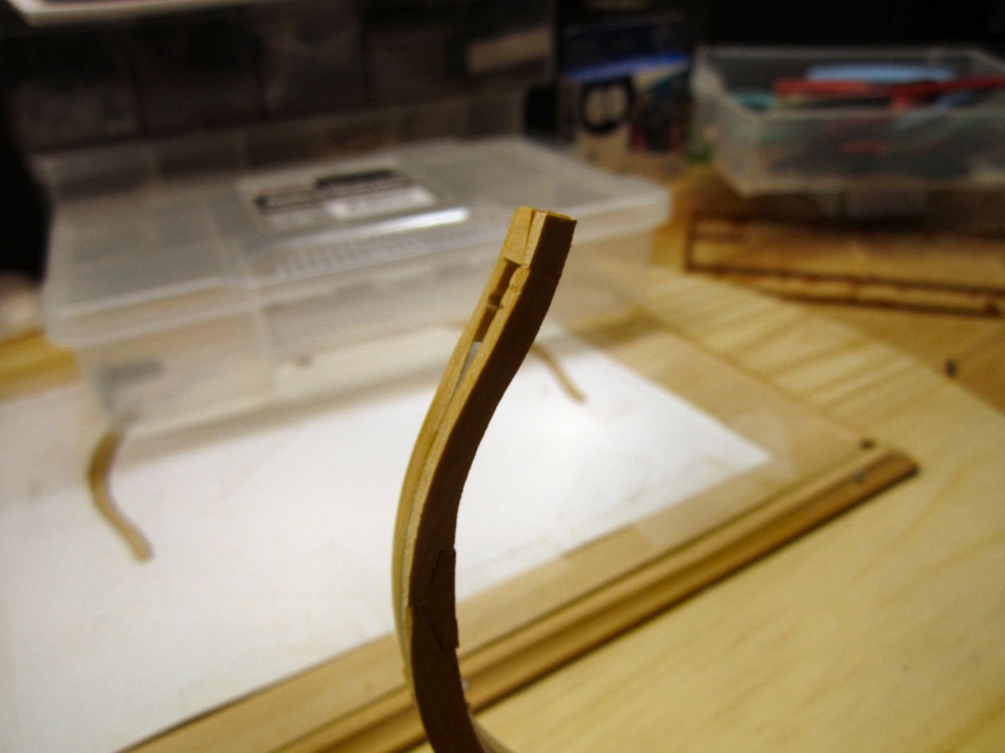
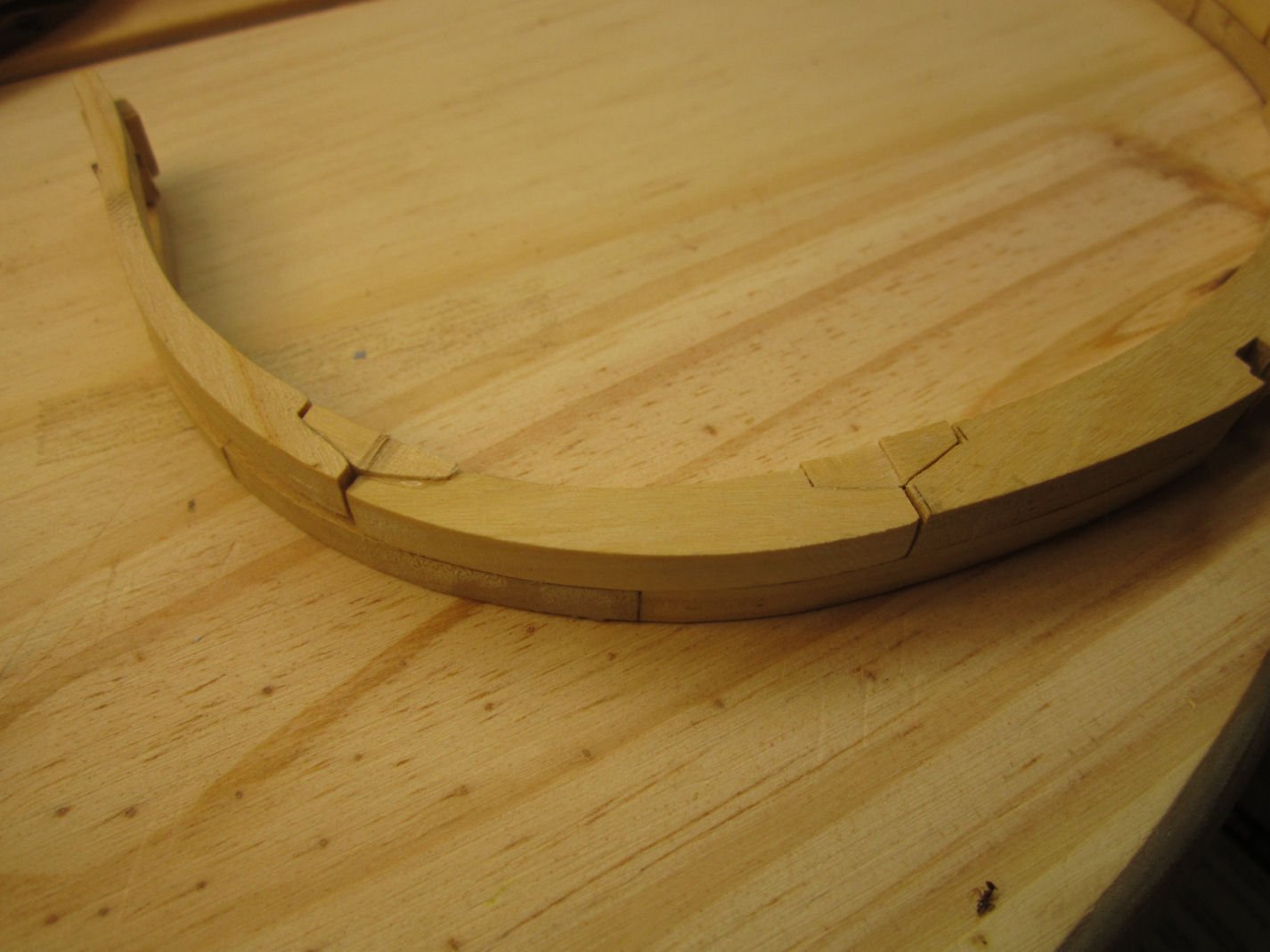
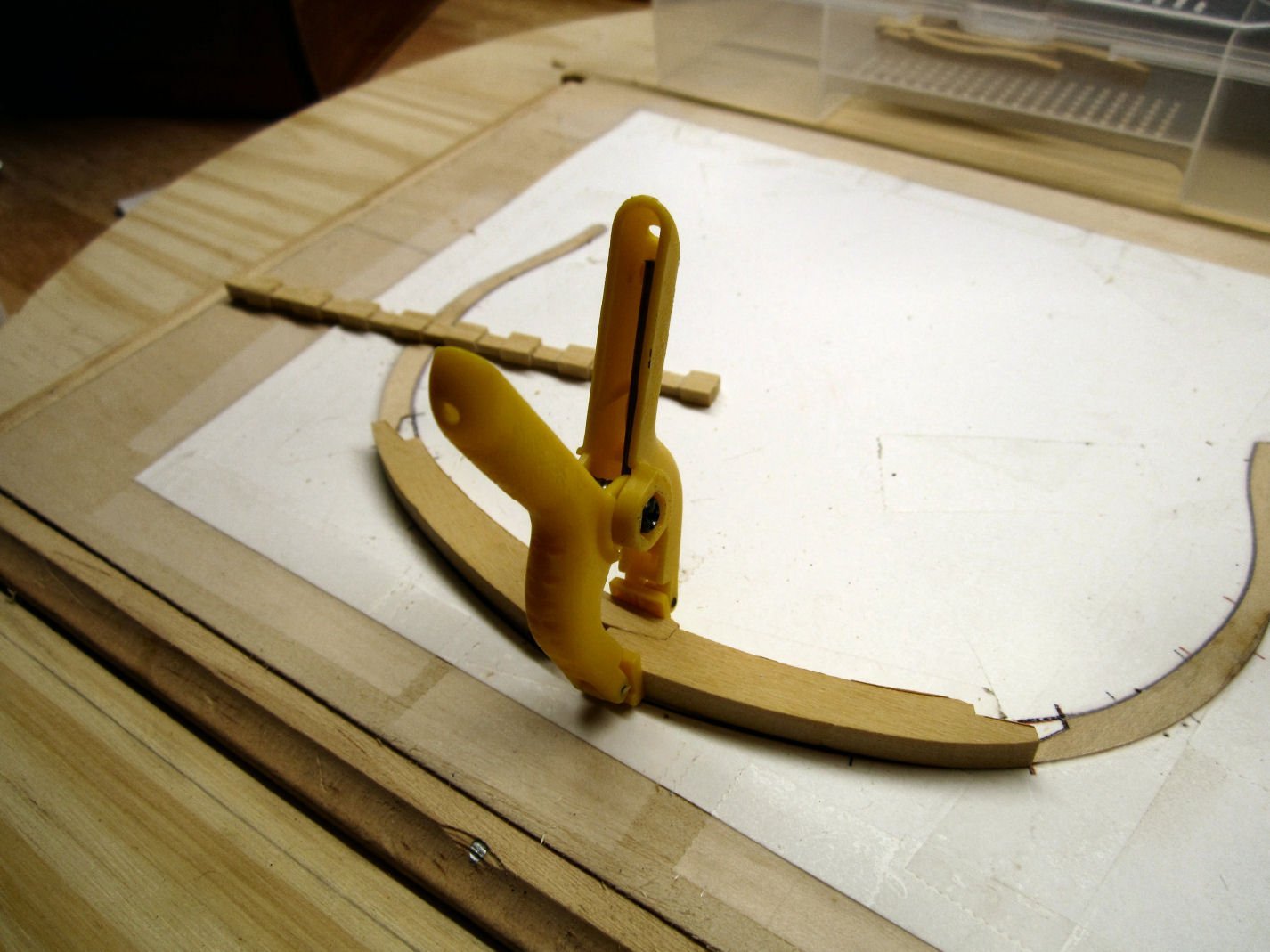
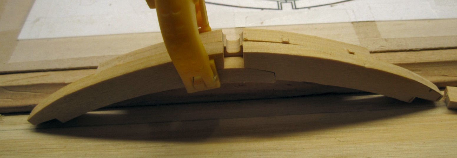
I cleaned up the unsquared area with my disk sander and got everything put back together, with the keel now fitting nicely. Then, for fun, I cutout the bottom piece of the upper half of the frame, and placed it on top of the lower pieces. Double *******! The lower frame curve was too shallow! So once again, do over.
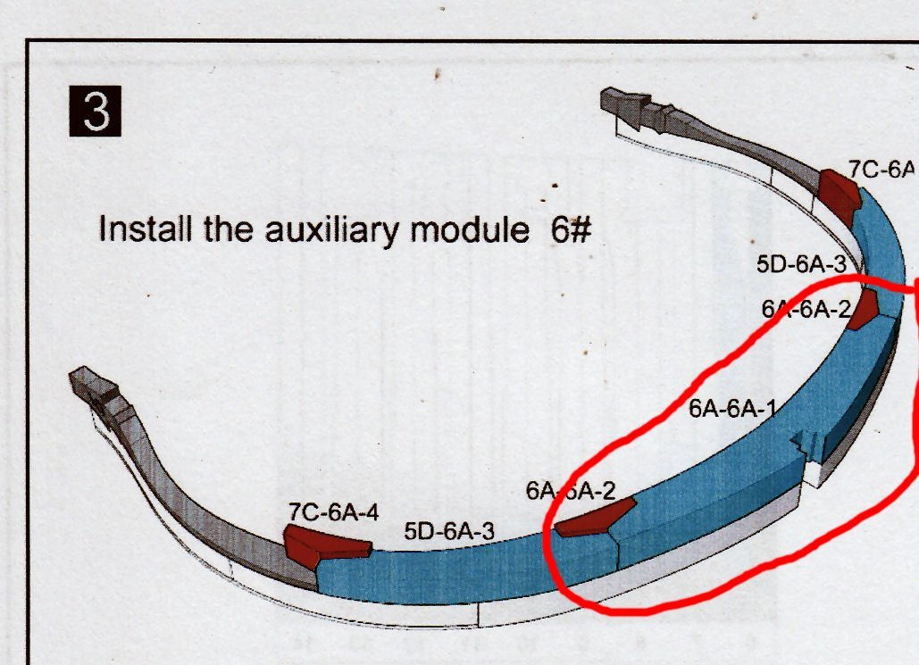
If you look closely you can see that the front assembly, does not have the same curve as the back piece (6A-6A-1). Note however how nicely the edges of the wider sections match. Sigh.

I cleaned up the outside surfaces of the upper piece to remove the attachment points.

As can be seen in the above picture, I then applied tape to the mating surface of the part, to prevent it from sticking to the lower pieces.
Then I glued the lower pieces in place and clamped the upper piece in place to align them. I had to sand the wedge areas of the chock to lengthen it to fill the longer gap between the two frames. There is enough meat in the part to do this.
After everything was correctly positioned I clamped the upper section to the lower ones, until the glue had grabbed, then removed the upper section, and placed a weight on the lower parts, to keep them flat.
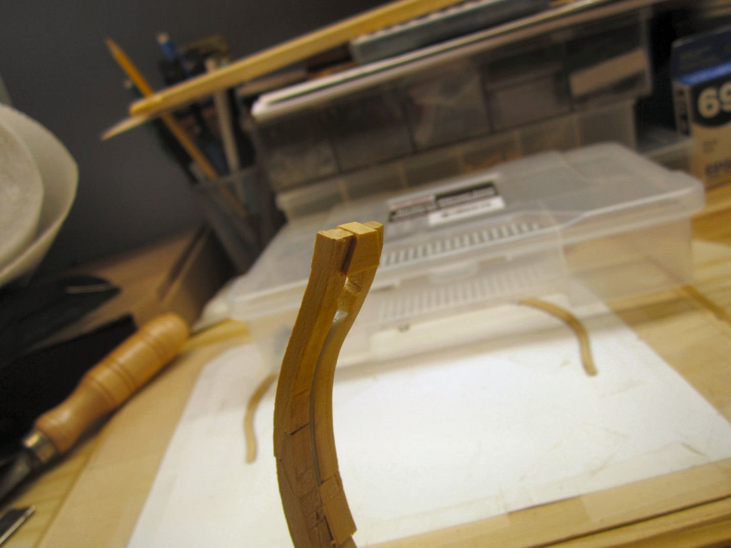
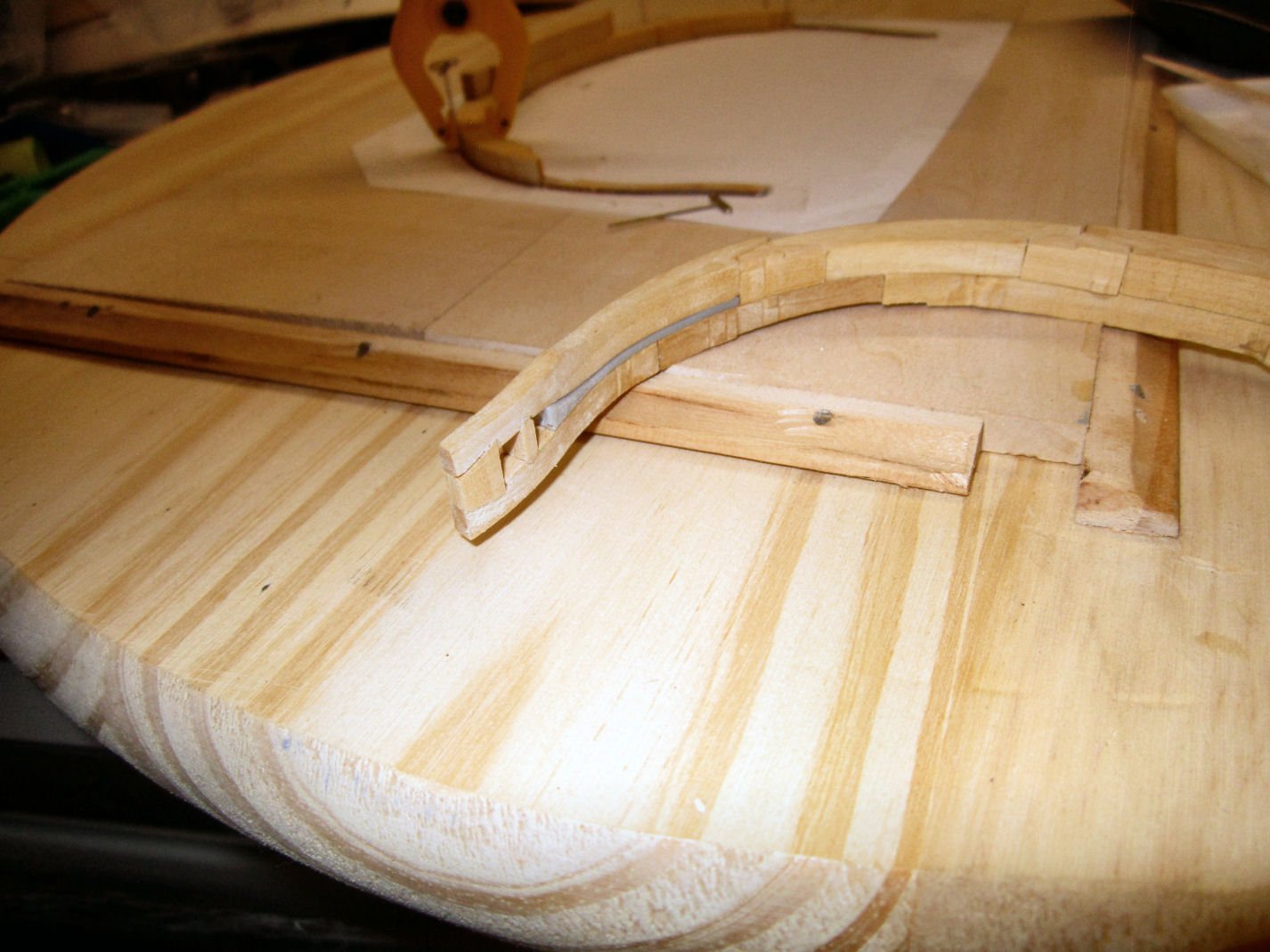
Finally I got the two curves to match, unfortunately, now the keel slot in the bottom half is too wide. Also unfortunately this frame is an end frame, and, naturally, the exposed side. I’ll figure out that problem later.
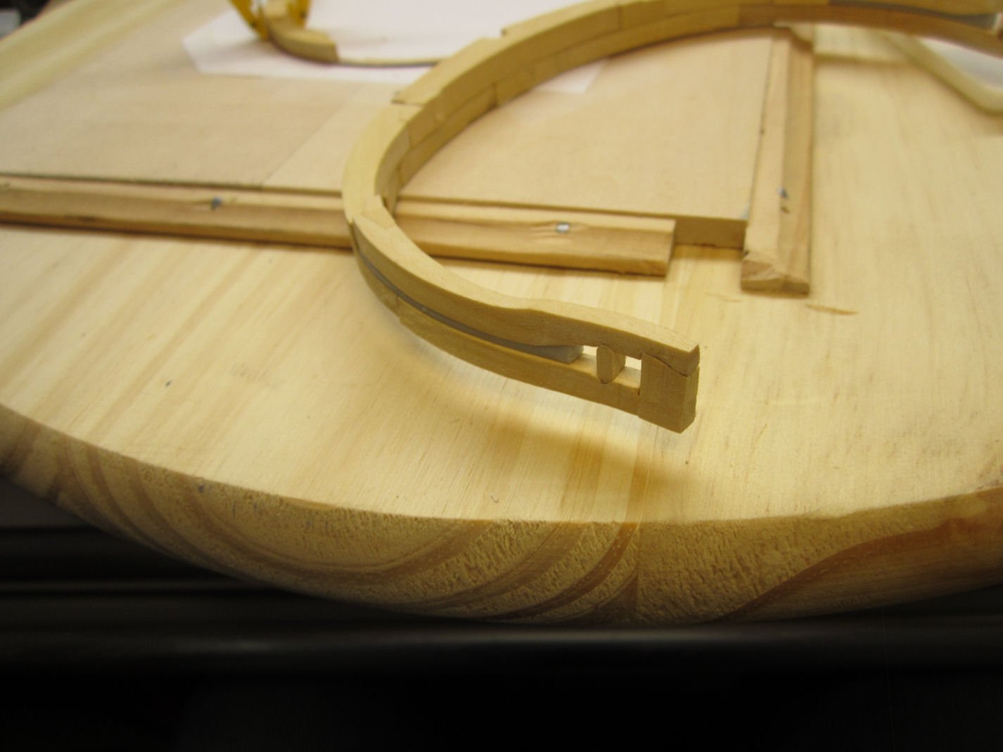
Here is a picture with the bottom section glued back together, and the upper piece set on top. Now the curves match! And, also now, the slots in the lower half are wider than the ones in the upper section.
After everything had dried, I glued the rest of the lower Frame 6 parts in place. Finally done with this assembly!
-
-
Great looking model, well done!
- mtaylor and Ryland Craze
-
2
-
Just found this build. Sorry to hear about your back trouble, but I'm glad you are feeling better! Interesting subject.
- Canute and Old Collingwood
-
2


ALGOMA STRONGFIELD by JKC27 - FINISHED - 1:200 scale - Equinox class lake freighter
in - Build logs for subjects built 1901 - Present Day
Posted
For the Bridge windows, perhaps you could glue strips for the mullons to clear plastic, and use the clear part as a structural part of the superstructure.