HOLIDAY DONATION DRIVE - SUPPORT MSW - DO YOUR PART TO KEEP THIS GREAT FORUM GOING! (89 donations so far out of 49,000 members - C'mon guys!)
×


thibaultron
-
Posts
2,944 -
Joined
-
Last visited
Content Type
Profiles
Forums
Gallery
Events
Everything posted by thibaultron
-
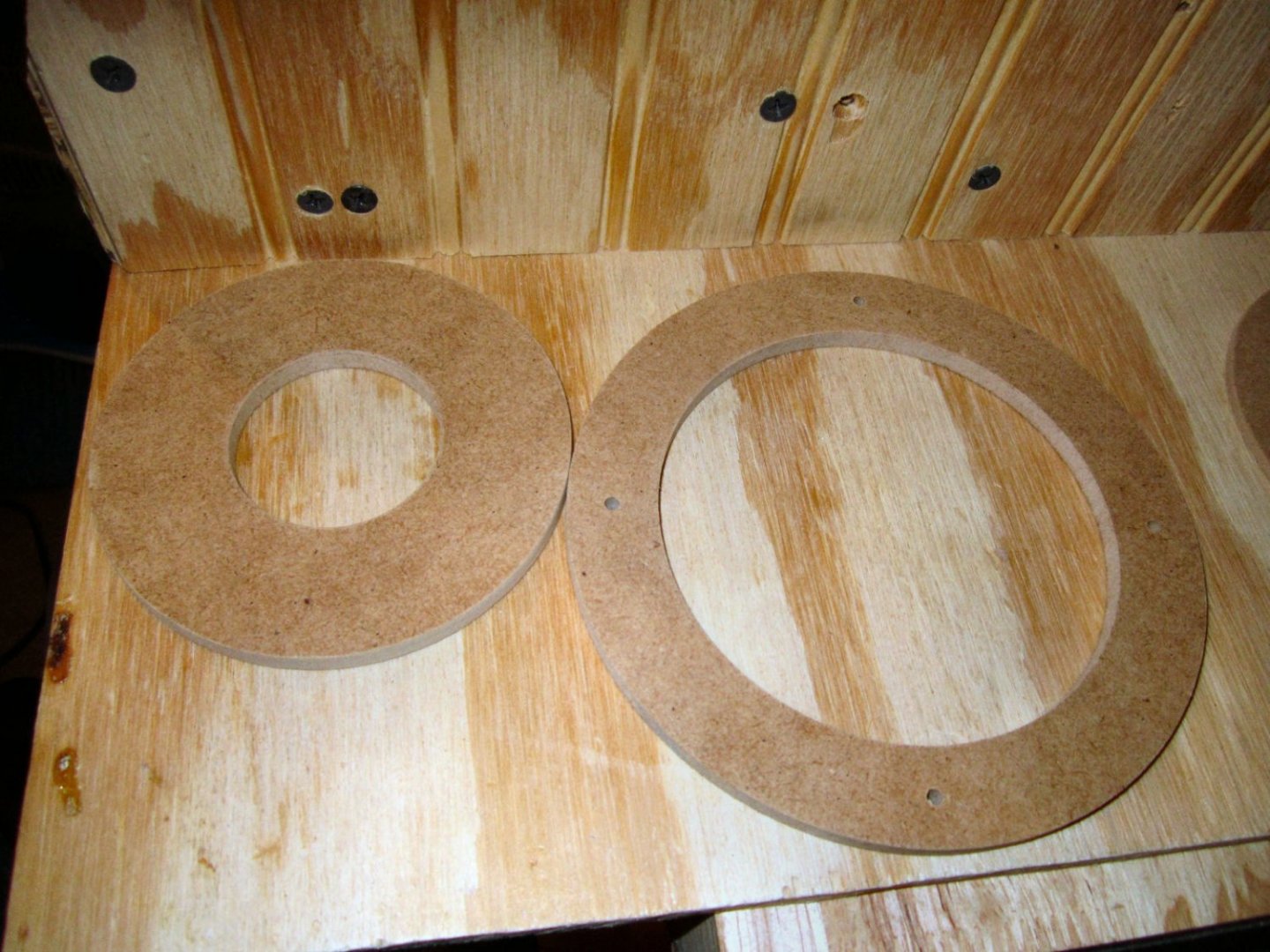
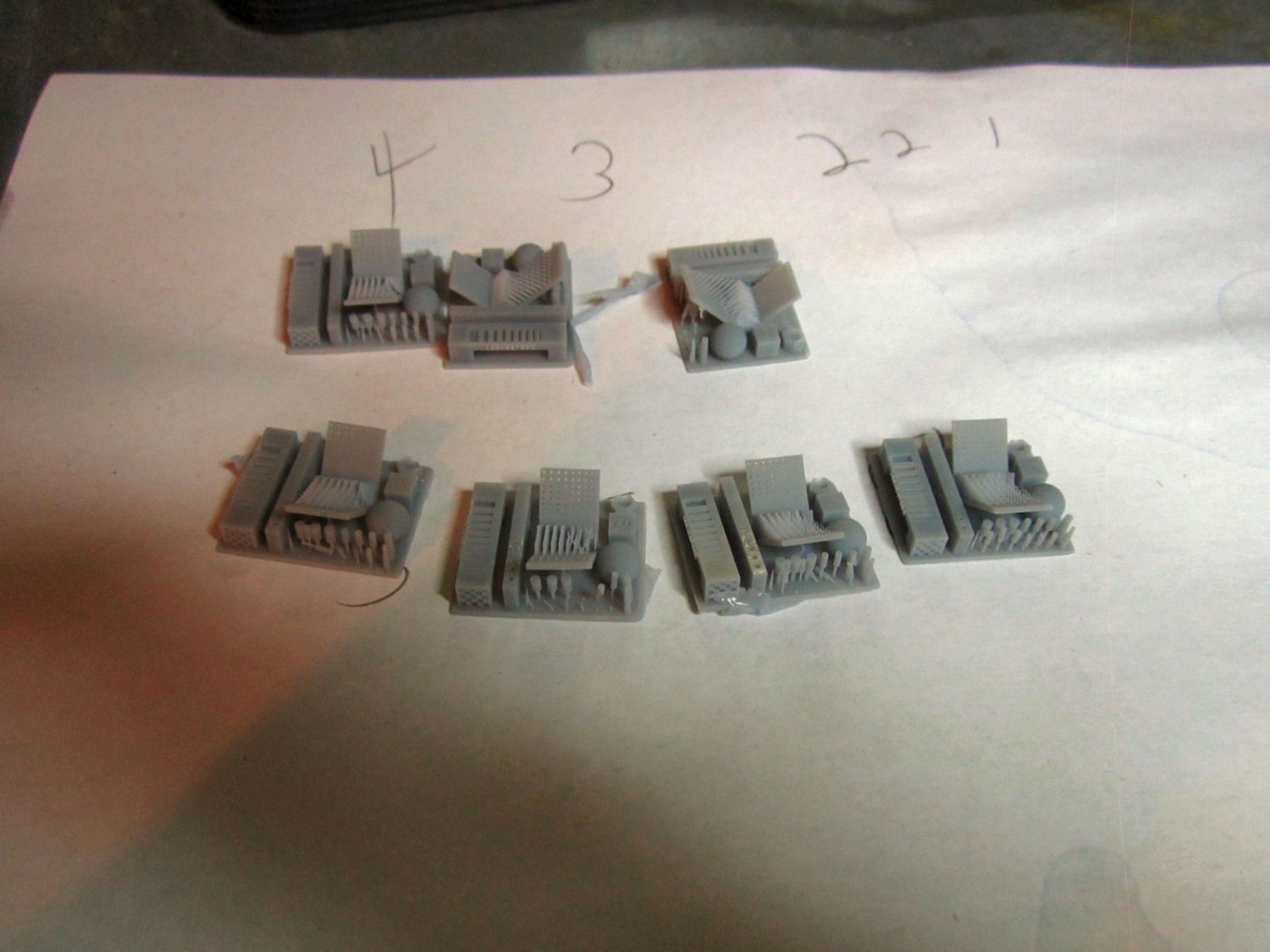
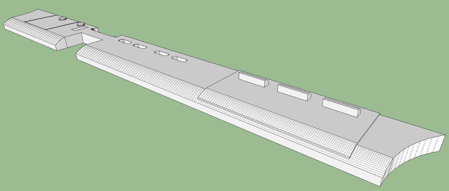
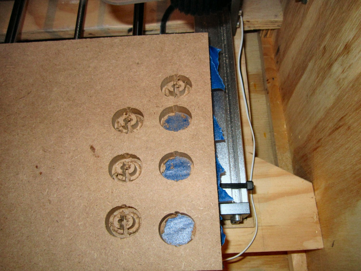
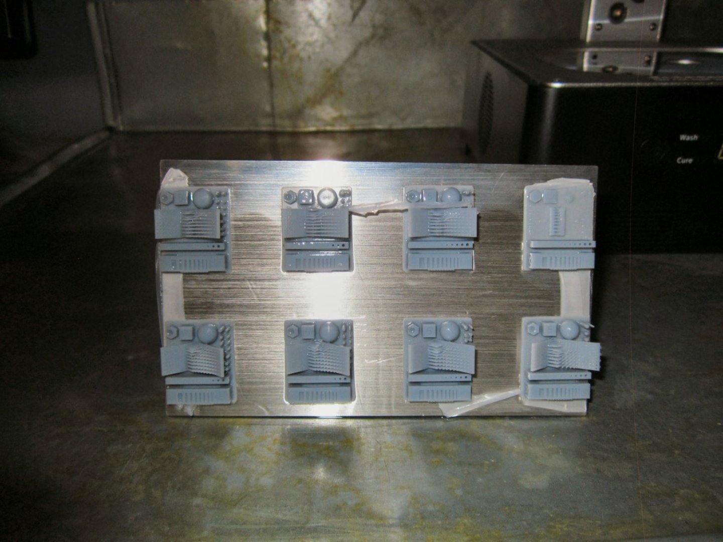
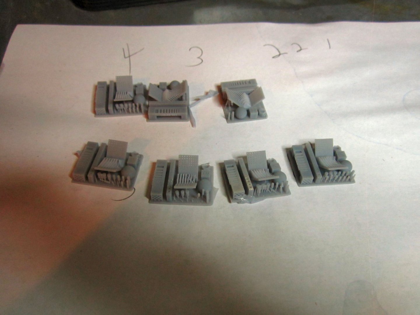
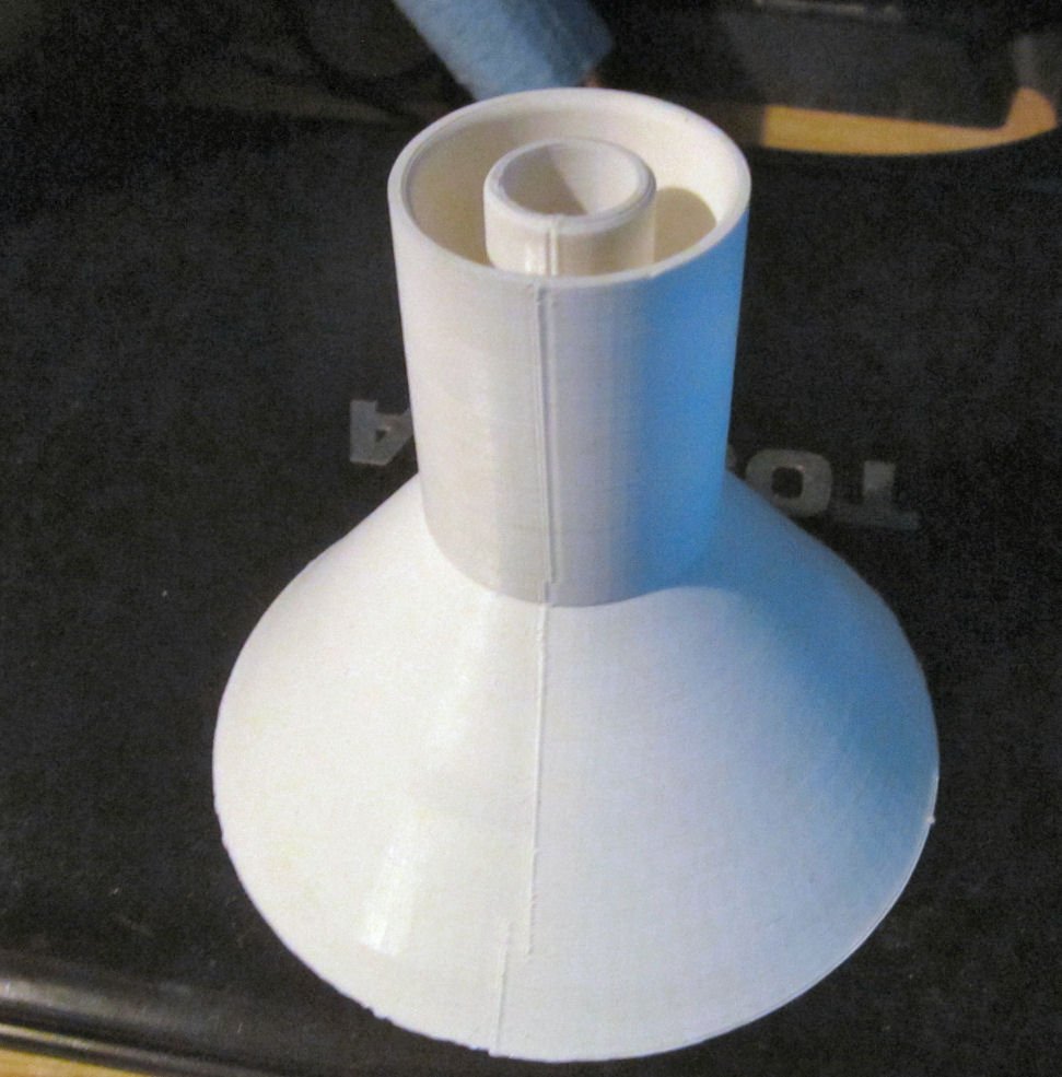
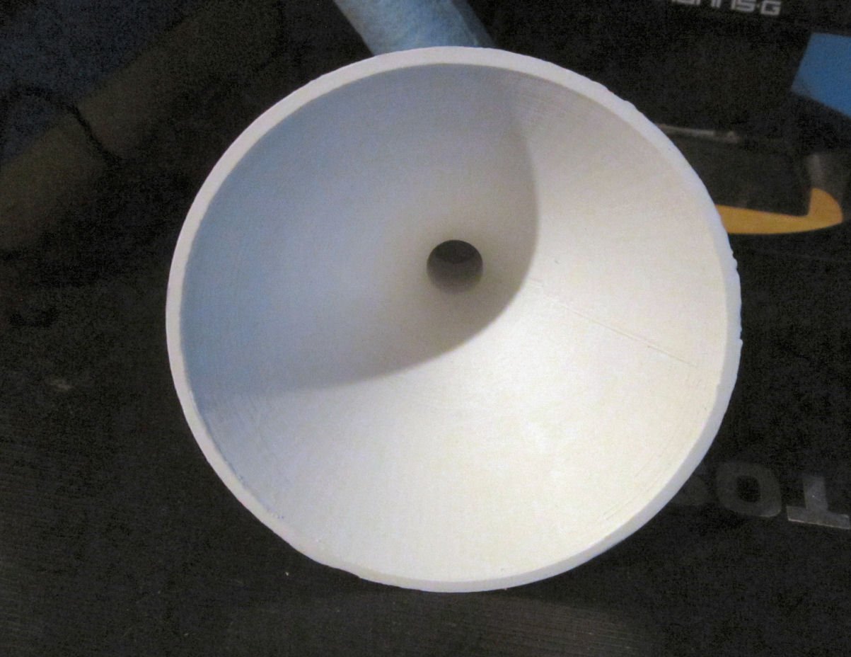
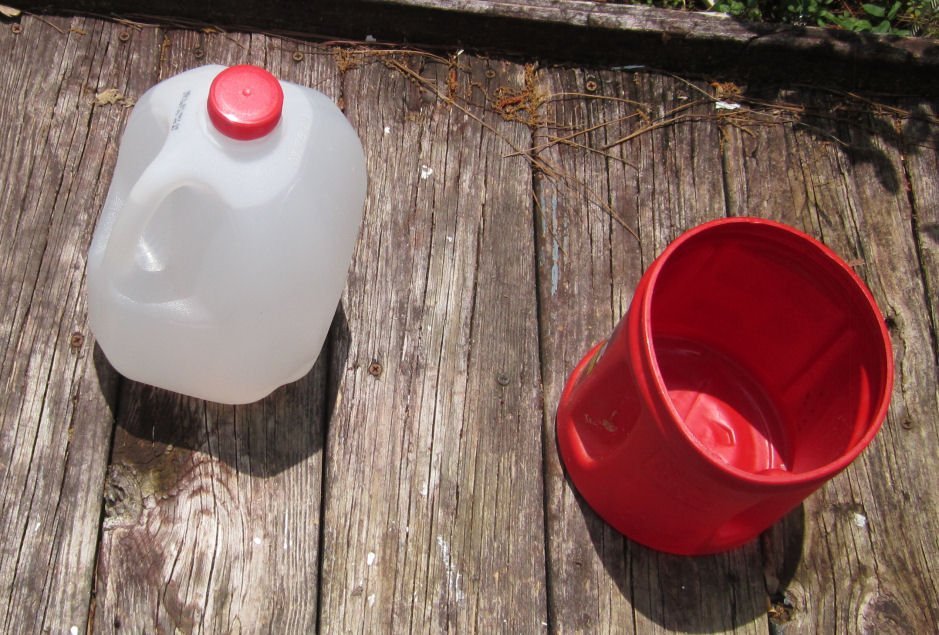
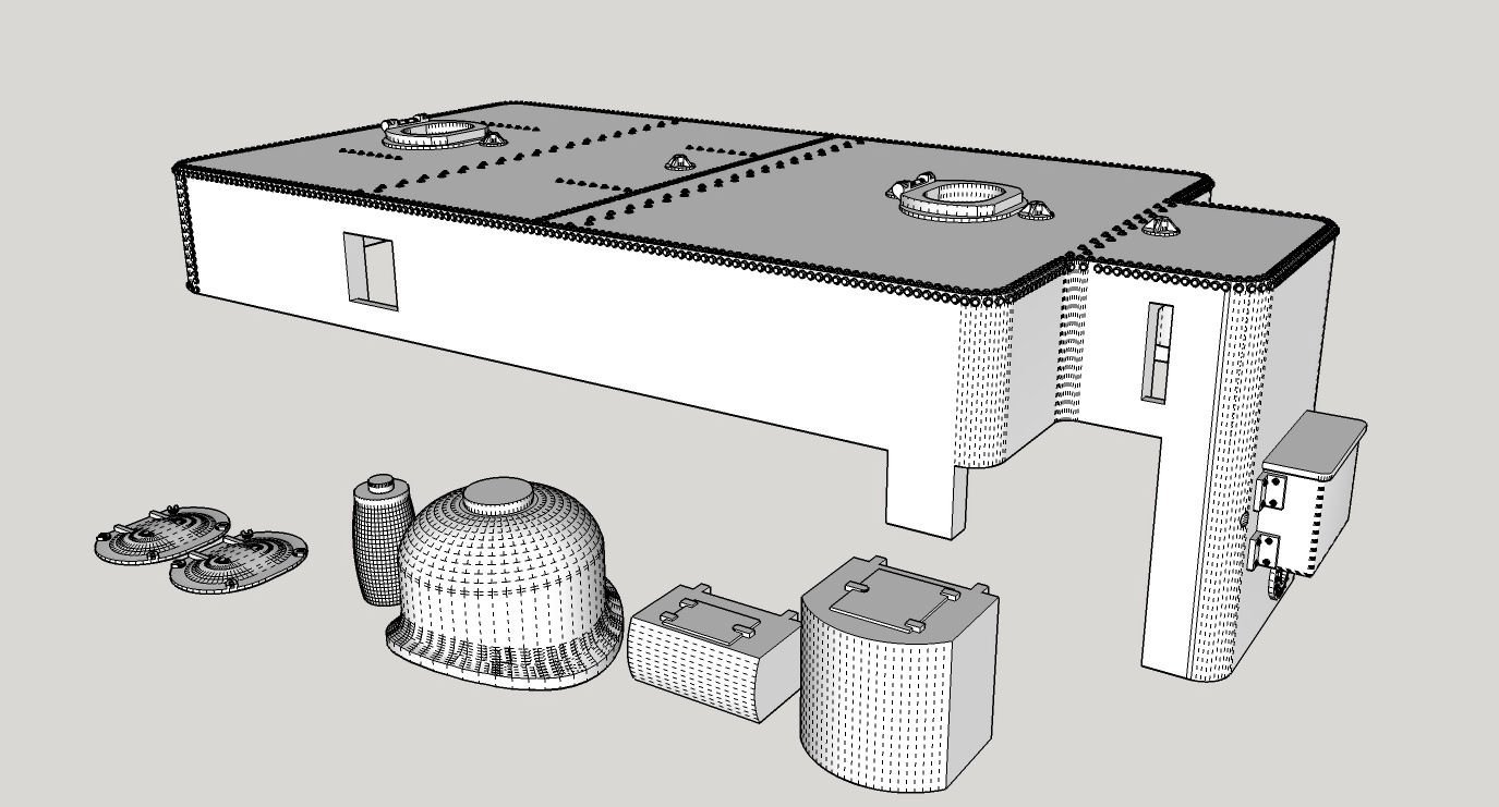
I finally got to print something, twice, with a major visit by clutezness! The original file USB thumb drive that came with my Mono 4K did not have Anycubic’s R_E_R_F file, the Resin Exposure test file! However, on their site they have Firmware Upgrades for the printer, and that includes the file, Yea! See the bottom of this tread, for a useful tip on cleaning stuck parts off of the FEP sheet!! This file prints out 8 copies of a printer “Torture Test” at various exposure levels (times). Starting at a very low time and working up in steps to a longer time for each copy. You then examine the copies to see which one/ones have the best results. From there you can try some prints of your own, varying the exposure time a little between/around the best of the times the test shows. This is a great test, but I had a couple problems with it. Firstly the file is in their latest format, which only their latest slicer software can read! Unfortunately, their latest software coughed and died on both of my computers! I found online that this is a common problem, even on computers that meet their requirements! The software does not read the computer configuration correctly! This leads to my second problem with the print, I don’t know which copy was printed at time X! The lowest exposure time is easy to determine, as it did not print completely, but what pattern they printed in I don’t know!! Here is a picture of the finished print, right out of the washing station, before curing. The lowest exposure time print is at the upper right, but does the pattern run right to left, then down to the second row, and repeat, or top to bottom/left to right, etc. This is the second print, the first one I forgot to tighten down the resin tray bolts all the way, and it was popping up each time the print lifted for the next layer. When I lifted the cover, the interlock kicked in and the print stopped. Not a big problem, I thought, until I could not get it to restart! I had to clean off the build plate and start over. As it turned out some of the first print stuck to the FEP sheet, and may have effected that second print. This is a photo of the parts after I removed them from the build plate, and cured them. Important Note: The first copy is missing, as will be explained at the bottom of this thread.Not knowing exactly what was being printed, I damaged some of the details, during handling. You can see I broke off some of the fat cylinders on thin stacks, at the bottom of the prints. I was hoping that the copies might be individually numbered, but no luck. After finding out what copy is printed at what exposure, I’ll redo this test. Now to the self-imposed disaster! While draining the resin from the tray, back into the bottle, I noticed the partial prints stuck to the FEP sheet, and while reaching for the plastic spatula to remove it, I knocked over the bottle! 2/3rds of my resin, all over the workbench and floor! My metal tray caught a lot of it, but not all! I spent the next two hours cleaning up the mess, while working through my entire supply of paper towels and gloves! My workshop floor is bare wood, so I still have some resin soaked into it. I cleaned it up as best I could, and left a fluorescent desk light shining on it, hoping the UV from the lamp will cure the resin still in the wood. Some lessons learned from this: 1. From now on, I’m only going to do one step at a time. Waiting to finish filtering the resin, and sealing the bottle, could have been done before I worried about the stuff on the FEP sheet. 2. I need to start really working on cleaning out the shop, so I can move the workbenches, and put down the vinyl floor, bad hip or no. 3. I need a larger supply of towels and gloves. 4. I need to clean out the shop, even if it hurts to get rid of some of the useful stuff. 5. If I have a selection of almost identical parts, number them after curing so I don’t mix them up while comparing them! 6. I need to further research the final curing times needed for my resin. I understand that over-curing them, can cause multiple problems, while under-curing is a Bad thing! 7. Don’t repeat this stupid mistake! 8. Did I mention, not knocking over the bottle again? Yes, sorry! 9. Get a proper organics filter mask, not the blue paper ones they supply. While there was almost no odor from the spilled resin, why take chances. 10. I need to get a smaller sieve type container to put small parts in while washing, the Wash and Cure supplied basket has holes that small parts would fall through. 11. Seal the seam between the sides and top of the printer base, with Capton(SP) tape. Some resin dripped into this seam, when I was pouring it into the resin tray. The Anycubic Wash and Cure 2.0 worked perfectly. I washed the parts while still on the build plate, so that I could keep track of them, and then removed the dried clean parts to the Curing Turntable in order. Anycubic specifically states that the washing tub Must be cleaned out after a session, not leaving the dirty cleaning solution in it. I was looking for clear sealable containers, to put it in, until I looked at one of my empty 1 gallon milk bottles, light bulb time! Three free 1 gallon containers now procured! Yes, I drink a lot of milk! You put the used solution in the clear container, and leave it out in the sun. After a week or so, the now cured resin particles sink to the bottom. And you can drain off the clear solution at the top. No, you can’t just cure the resin in the solution in the curing station, you end up with a resin sponge welded into it. Thank you, YouTube, for the video on that Fail! The slow curing and settling in the closed container, is what is needed. There are expensive ways to more quickly clean the solution, but I’m not doing the printing as a business. For cleaning the parts on the plate, a full gallon is needed, but if you can place them loosely in the basket, you only need to add enough to cover the parts. I will have to come up with some sort of apparatus to force solution through the interior of hollow parts, perhaps a large ear type squeeze bulb. Overall, I see that I will be able to print the parts I need to build and upgrade my models. A big “Thank You” to my son, who 3D filament printed me a custom funnel that fits the top of the resin bottle, when filtering the resin back in!! It fits inside the bottle top, as well as outside the threads for the cap, so the funnel is perfectly stable, unless you stupidly knock the whole thing over! Here is the used solution in the milk jug, with the plastic coffee jug I used for spot cleaning parts, the build plate and the resin tray. As the print was small, the solution is pretty clean, but it will be even cleaner when I reuse it. The Mono 4K printing area is sealed during printing, with no “Smell Dissipating Fan” as used on some printers, forcing the fumes out, so I may not need a vented enclosure. Having some sort of extraction fan would not be a bad idea, though. I may also invest in one of those charcoal fans that fit inside the print case. Now, to the problem of the parts stuck to the FEP sheet. I tried a plastic spatula, and my fingernails, and only accomplished scoring and dinging the FEP surface. Then I remembered a video I watched, on how to solve this problem. I poured enough resin in the tray to cover the bottom, and placed the failed number one print into the tray, at a corner opposite the stuck on parts. Then I used the exposure test, for when you are visually checking that all the “spots” are illuminated on the LCD screen, to expose the whole resin area, for about a minute or two. This created a solid raft in the tray, that also fused the stuck parts and the sacrificial print together . I drained the uncured resin back into the bottle. By lifting the print, the whole thing (raft and stuck parts, pulled off cleanly, with no further damage to the FEP! Here is a use for some of those old support structures you have left over! Sorry no photo of this, as my last pair of gloves were covered in resin, while cleaning up the mess I’d made. The first two items I will be trying to print are a skirt for a passenger diesel locomotive (fits between the two trucks to make the loco look more streamlined)(two prints per loco), and an oil bunker to convert a steam locomotive from coal fired to oil fired. This model includes both tender tool boxes, the hatch covers, a new sand dome for the loco, and the loco crew water bottle that mounts on the front of the tender. The holes in the sides of the bunker, are there to clear the existing portions of the tender shell coal bunker. The bottoms of the holes are cut out after printing.

-
The advantage of the dummy props for RC, is that the drag they create, require more thrust from the operating ones, of course. The extra thrust sends more water past the rudders, giving you more maneuverability. Also to get a properly shaped wake and bow wave the speed should be the square root of the scale, not a "Scale Speed". The square root is what they use in all the naval test tanks. For instance, the Missouri steamed at about 35 to 36 knots top speed. Your model should go about 1/14th of this, not 1/200th.
-
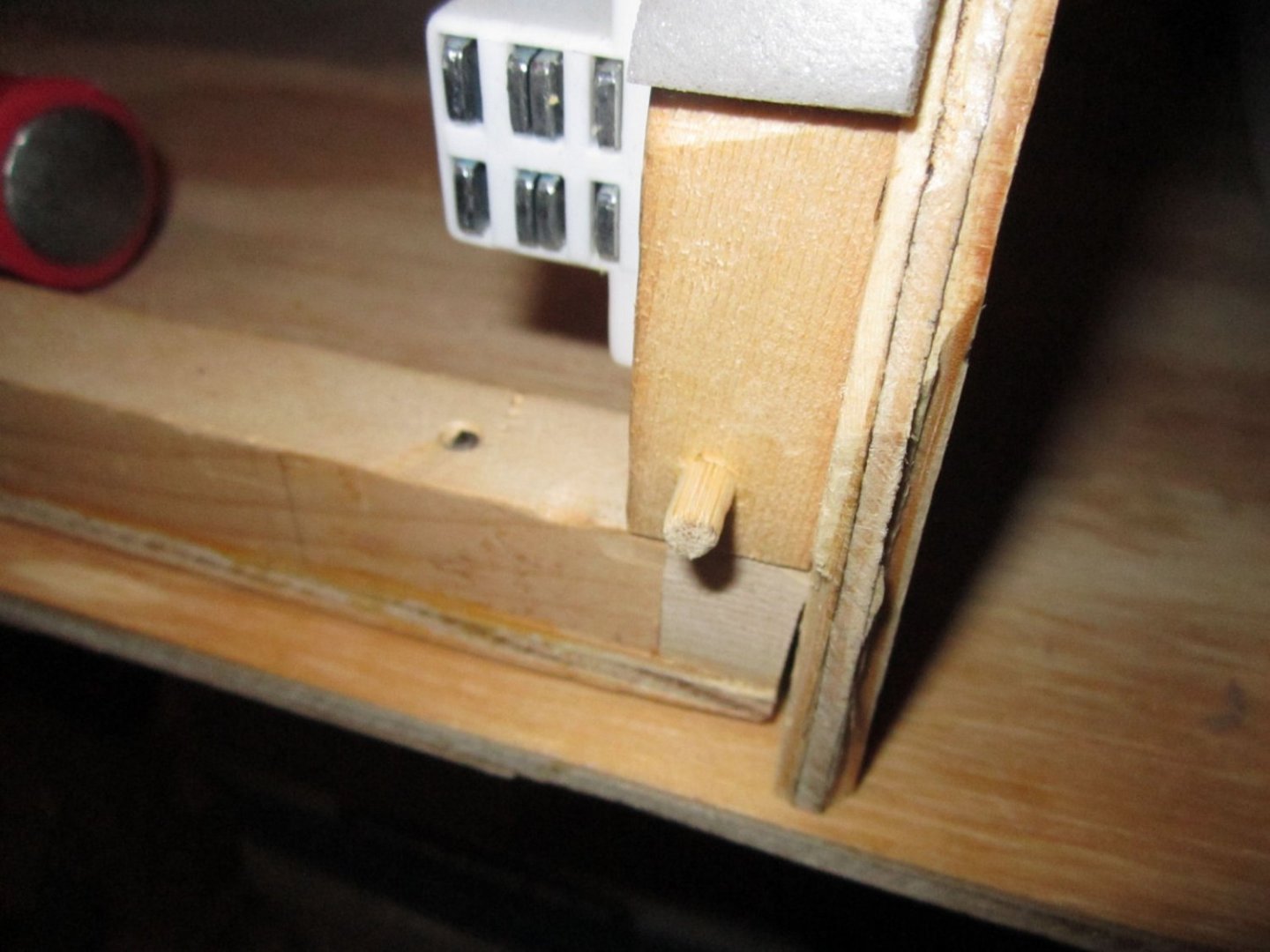
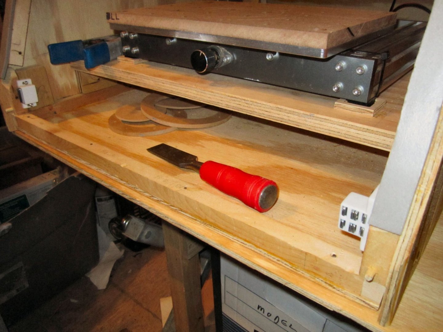
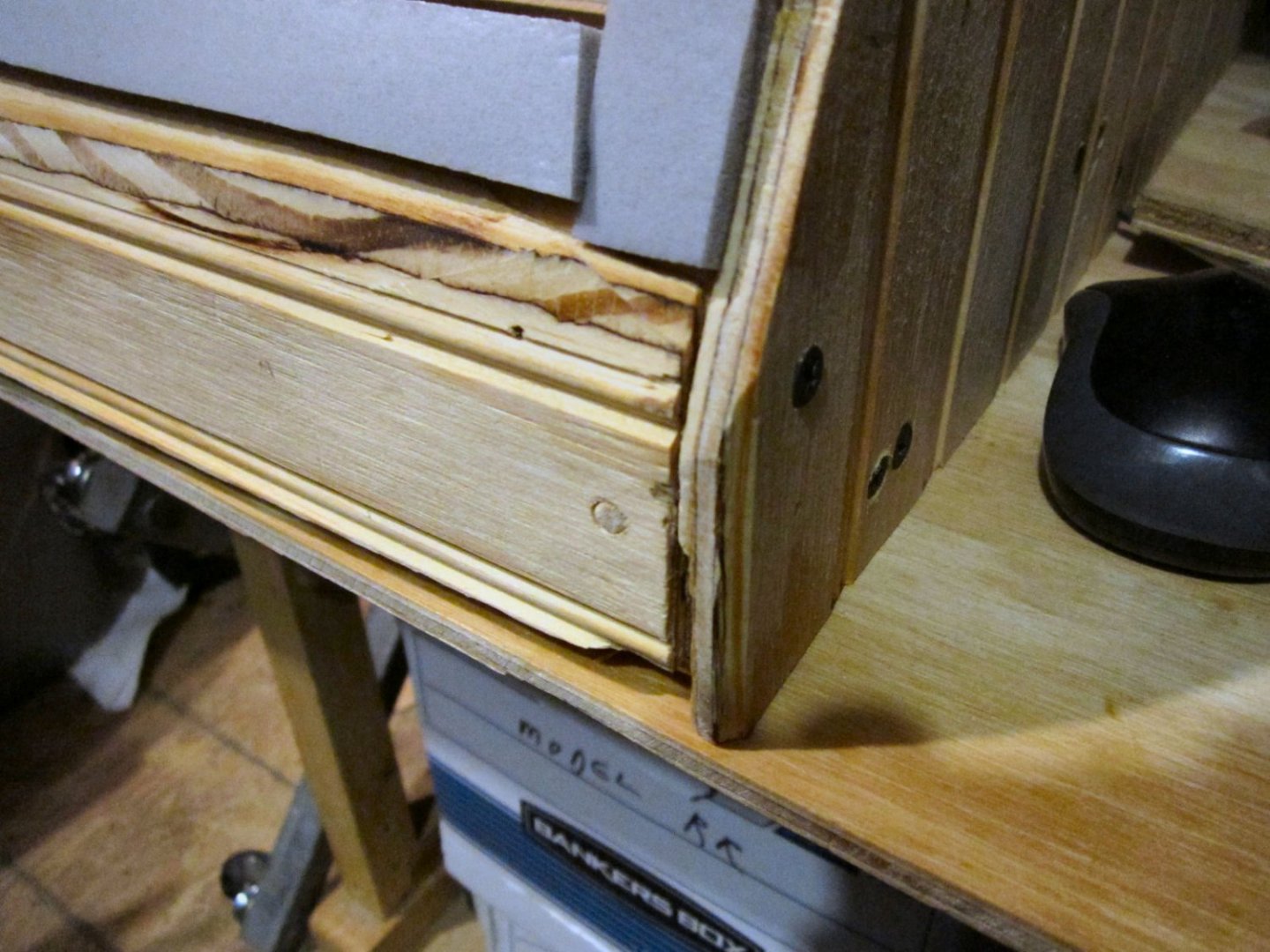
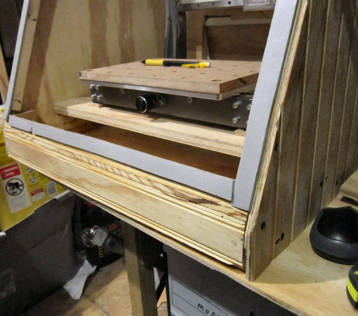
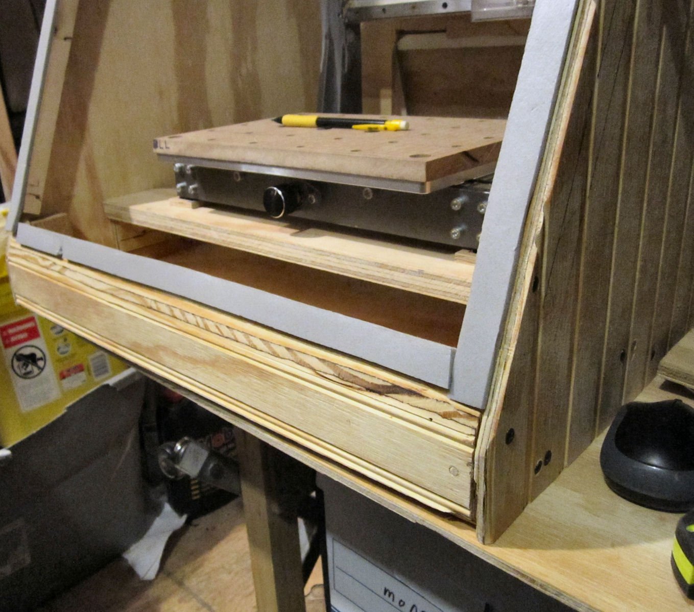
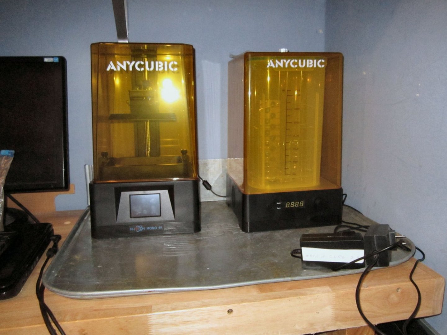
Today I made a tray to set my resin printer and washing station in. After looking at a few videos, they recommended having the printer on a tray, to catch any resin spills, and thus keep it off your work bench/table. I had not considered that before. I was looking around for a suitably sized plastic tray, when I remembered an old metal tray I had laying around. The tray is a metal drip tray, sold for putting under leaky cars. This one had been used to protect my wood trailer floor, when I helped a friend pick up a used car engine. Anyway the tray measured 25 inches X ~36 inches, which was too large for my 20 inch wide workbench. It also had some bad dents at one end, where the motor had pressed in during transport. Cutting the tray to a final length, after bending, of 19 inches long (from the 36 inch length), would leave me with a 25 inch wide by 19 inch deep tray. This was perfect for placing the printer and wash station side by side, with room to insert the USB thumb drive in the slot in the side of the printer. Why Anycubic put the power and USB slot on the side of the printer, and the wash station power switch on the back, I don’t know. Front mounts would be much better. I cut the tray with a 4 inch lip, which I bent up to form a vertical back to the tray. In the near future I will fill the two back corners with caulk to seal the area I cut for clearance for bending this. I could have just left the tray intact and bent the whole end up, but in my case, this would have interfered with the brackets of the shelf above the two machines. In the next week I will cut a slot in one side of a ¾ inch square strip, and place it over the exposed cut at the back of the tray, even with filing, that edge is still sharp enough to cut me. If I do make another one (see below), I’ll make the back lip higher, right now it is level with the top of the printer base. Here is a picture of the tray, as it sits right now. You can see the tab I bent up at the back. How did you bend it, you ask? I carefully flattened the outer area of the tab sides, leaving the tubular edge intact. This allowed the tab the clear the area at the bend to bottom lip area. I clamped it between two pieces of wood, and after hand bending it a little, went at the corner with a rubber mallet. This is one of the corners that I have to caulk. You can see the area next to the tube edge that I flattened for clearance. It might not look flat, but the wrinkles you see are where the tray was bent, they are “flat”, but the edges still leave a visible mark. I will probably buy a new tray, and fabricate another one. This one is not quite flat, due to a couple of twisted areas that I bent down as best I could. Moving the engine caused some damage that caused this. The tray is pretty good, but the weight of the machines is not great enough to press the floor tight to the table. The trays are not that expensive (at least not a couple years ago when I bought this one). And keeping the printer as close to flat on the leveled table as possible is best. I’m going to run a test print tomorrow, to dial in the correct settings for my resin, and see how bad the stink is. The later will determine if I have to build a vented enclosure for the printer.
-
 Thanks!
 -
I've always thought it was 1600X1200. Has it changed recently?
-
Its a little late, but you do have another coat of paint to apply. The Model Railroad Suppliers sell "Rivet Decals" These are little epoxy (I think) dimples on decal film. They might have some with the spacing you need to replicate the ones for your model.
-
Perhaps a coat of thinned PVA, before painting, or a varnish coat.
- 201 replies
-
- 3
-

-
- SD 14
- Marcle Models
- (and 1 more)
-
Bluenose II copyright infringement lawsuit
thibaultron replied to Nirvana's topic in Nautical/Naval History
Opps, mistyped. -
Bluenose II copyright infringement lawsuit
thibaultron replied to Nirvana's topic in Nautical/Naval History
It was settled in 2014, with neither party winning the right to the copywrite, but the government paying the family $300,00. -
249! "Doctor My Eyes"!
-
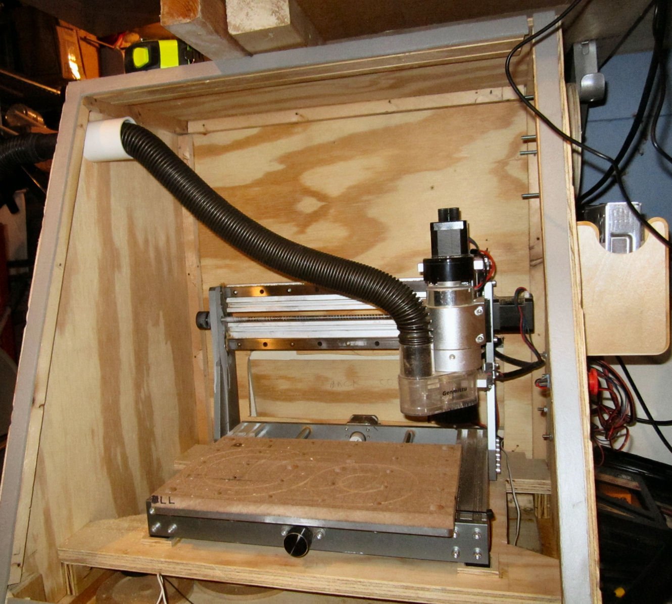
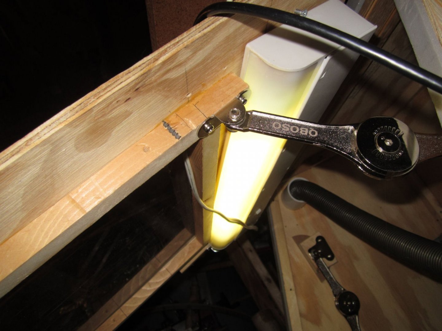
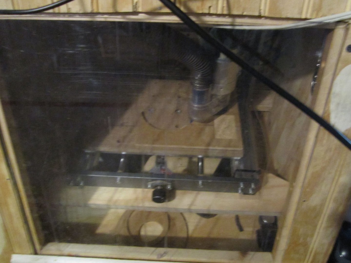
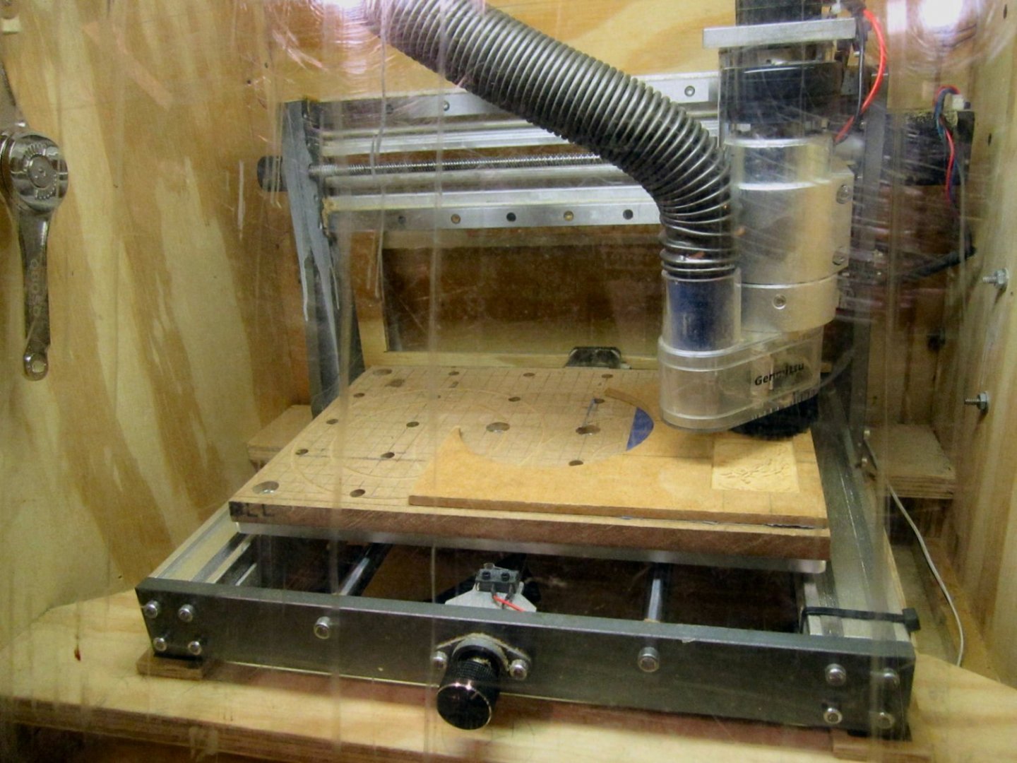
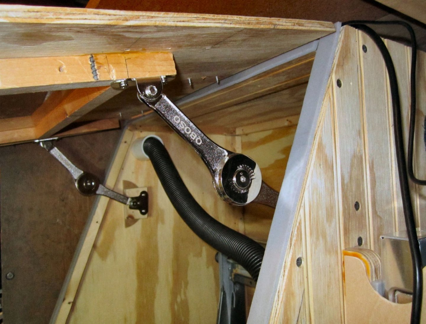
Part 027 – “Let There Be Light!” One quick update. I added a light to the inside of the enclosure. I had been waiting until I could get a LED light, but time passed and I already had a spare fluorescent one lying about, so I installed it. I was going to install it under the top of the enclosure with the light pointing forward. The top of the door would have shielded it from glaring into my eyes. After some consideration though, I realized that when I was working on it, with the door open, it would be shining right into my eyes. Looking at the door, I realized that I could mount it between the supports, and then it would both well light the machine, with the door closed, and shine the light down past me with it open. I originally had it mounted parallel to the upper window support, but the light case hit on the vacuum connector, when I tried to close the door. By lowering that corner to touch the support, I got just enough clearance. For now I’m running the cord out through the window opening. I need to stop by the hardware store, and pick up some cable clamps. The wire is long enough that I can extend it out through the back door area. If I was going the build another enclosure, I would move the vacuum connector back a bit to clear the light case. With the light added I defiantly need both of the door supports, due to the weight of the light. The one support is not attached in the pictures, as the light blocked access to the mounting screw. I’ve fixed it since then. The difference with the light is amazing! I can now clearly see the work pieces during carving, and when changing bits, etc. Before I had to shine my modeling lamp into the case to see some areas. The first picture shows the enclosure without the light. The camera is more light sensitive than my eyes, so it is even darker in real life. Here is it with the light on. It makes me want to get a new piece of Plexiglas for the window! The vacuum hose was a little too short, after I trimmed it, and it kept popping out after 10 minutes or so, during the cuts on this piece at the far right of the machine. I was able to fix it by wrapping a layer of tape around the nozzle. This had the added benefit of allowing me to put a slight twist in the hose, to make it fold into a little better configuration, when the spindle was at the extreme left.
-
Just ordered a copy, also. Thanks!
-
Syren Serv-O-Matic Server Machine
thibaultron replied to Casey's topic in Masting, rigging and sails
Chuck said that he was shutting down the site for a few days. It will be back up after that. -
Its not a book addiction, its just you channeling your inner Librarian!
-
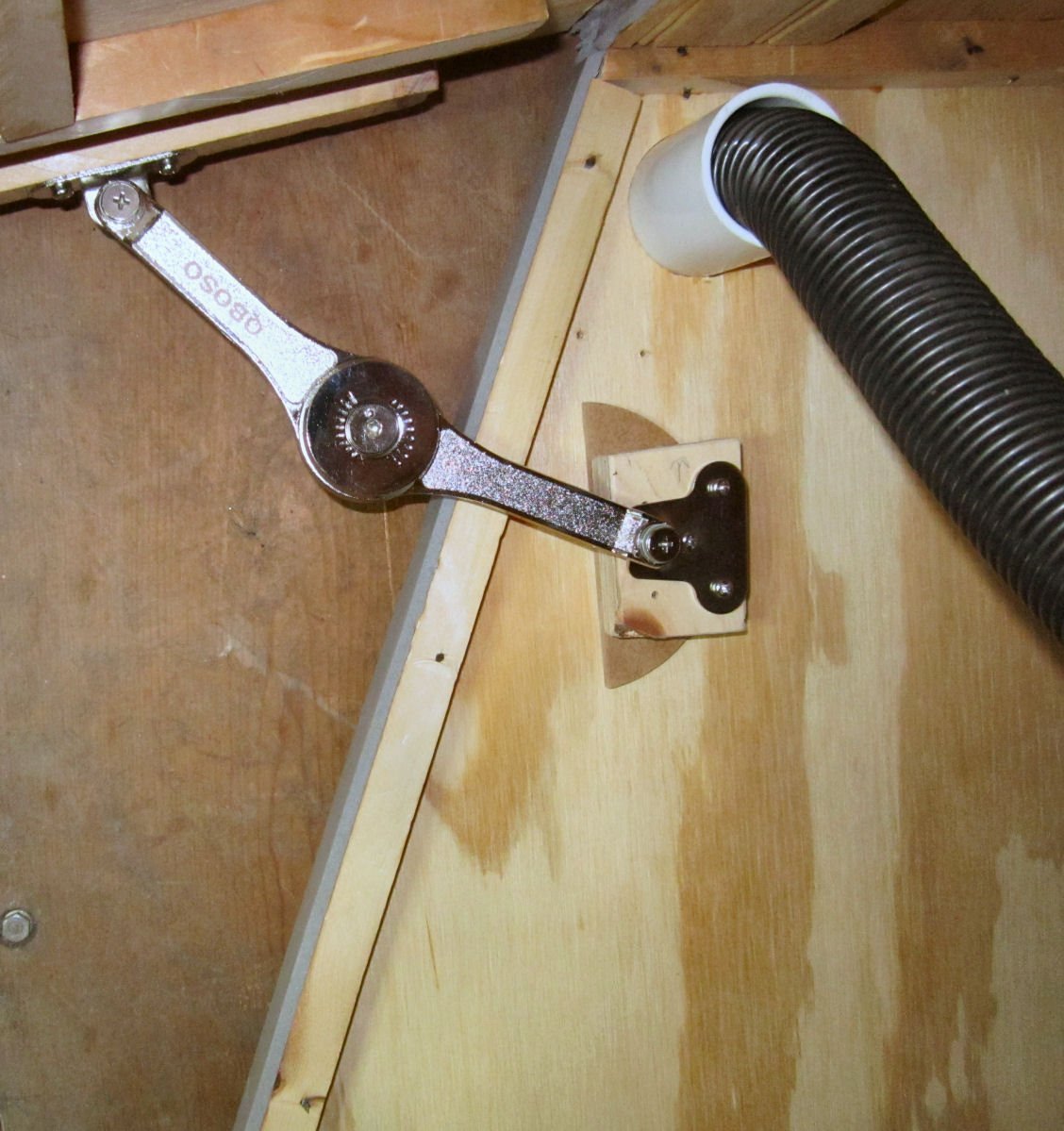
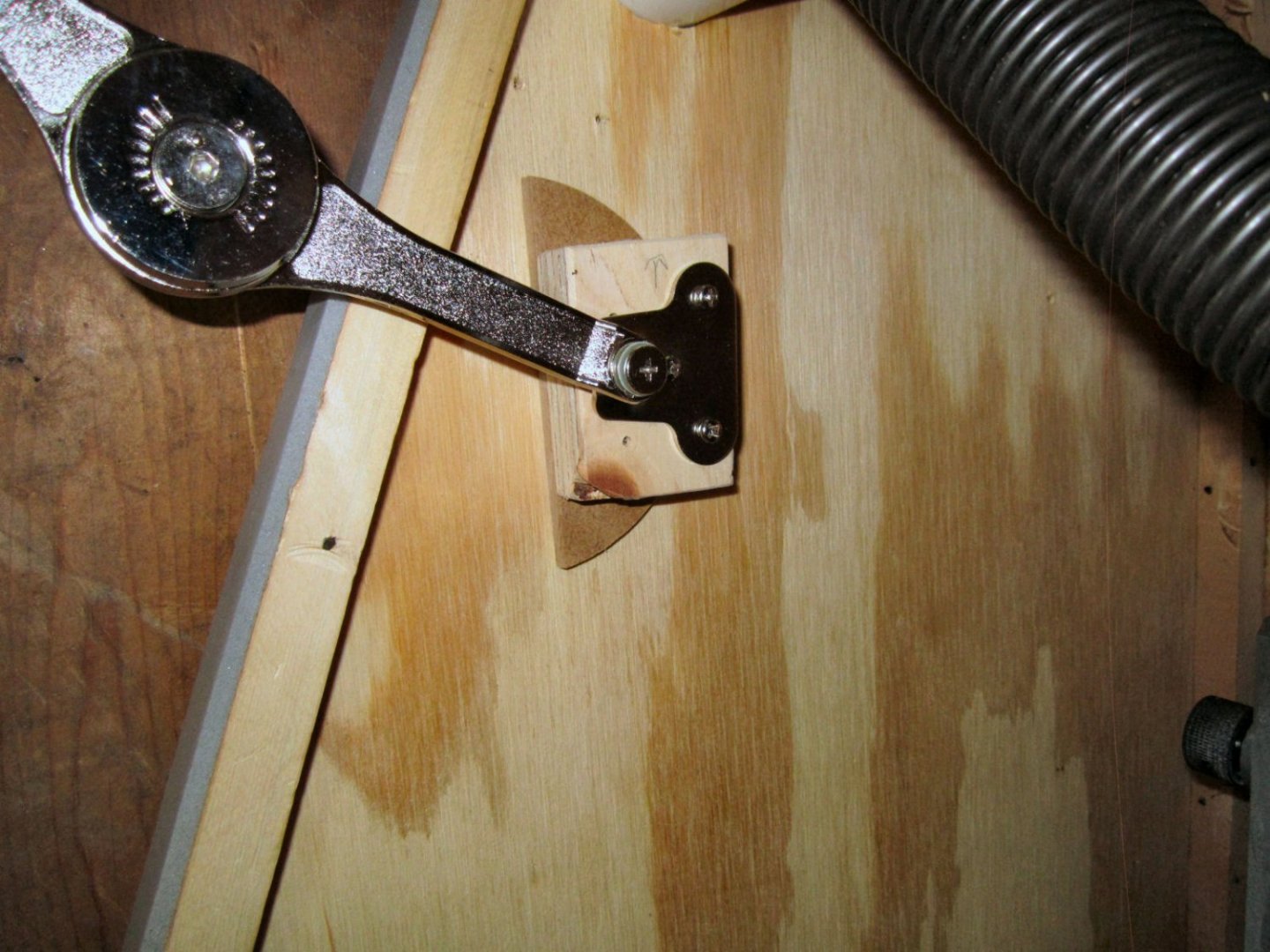
Part 026 – Door Supports. I found some cabinet door supports in my junk collection, so I used them for the enclosure door. I used the setup measurements on the package for a 90 degree opening, but as it turns out the supports are designed to close toward the hinges, and I needed them to open away, to clear the vacuum hose. It took a bit of fiddling, but I managed to find the “Sweet Spot” using the same mount location on the cabinet side, and moving the door mount location. It doesn’t give me a full 90 degree swing, but it is sufficient to allow free access. In the picture, below, I had to add spacers on the cabinet side mount to clear the ¾” square sidewall support. Then while the instructions show that end being flush mounted to a cabinet, the hinge section was hitting the support, and I had to add an additional ¼” spacer. Cheap manufacturing. Here is a shot of the door, after I finished installing the supports on both sides. The brown board on the far side of the cabinet is simply a temporary view block, to hide the clutter on the back wall. The supports open easily then use an internal friction lock to hold the door up. You press down on the door to close it. Not as nice as a physical interlock, but it works. I’m sure that if I left it open for a few hours, I’d find the door closed when I came back. What the heck, at least they were “Free”, in the sense I already had them laying around. This will probably be the last part of this thread, the enclosure is pretty much finished. All I have to do to finish the enclosure is add magnetic catches, toggles to hold the top of the door window, and a light. Nothing very interesting, or difficult.

-
Wow, just Wow!
-
Great news!!!
-
Welcome, and thanks!
-
Got my AnyCubic 4K Mono two days ago, and bought some Elegoo resin. Have to build an enclosure for it before I can do anything with it though. My shop is not well ventilated.
-
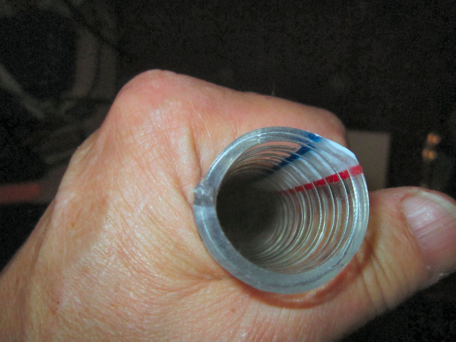
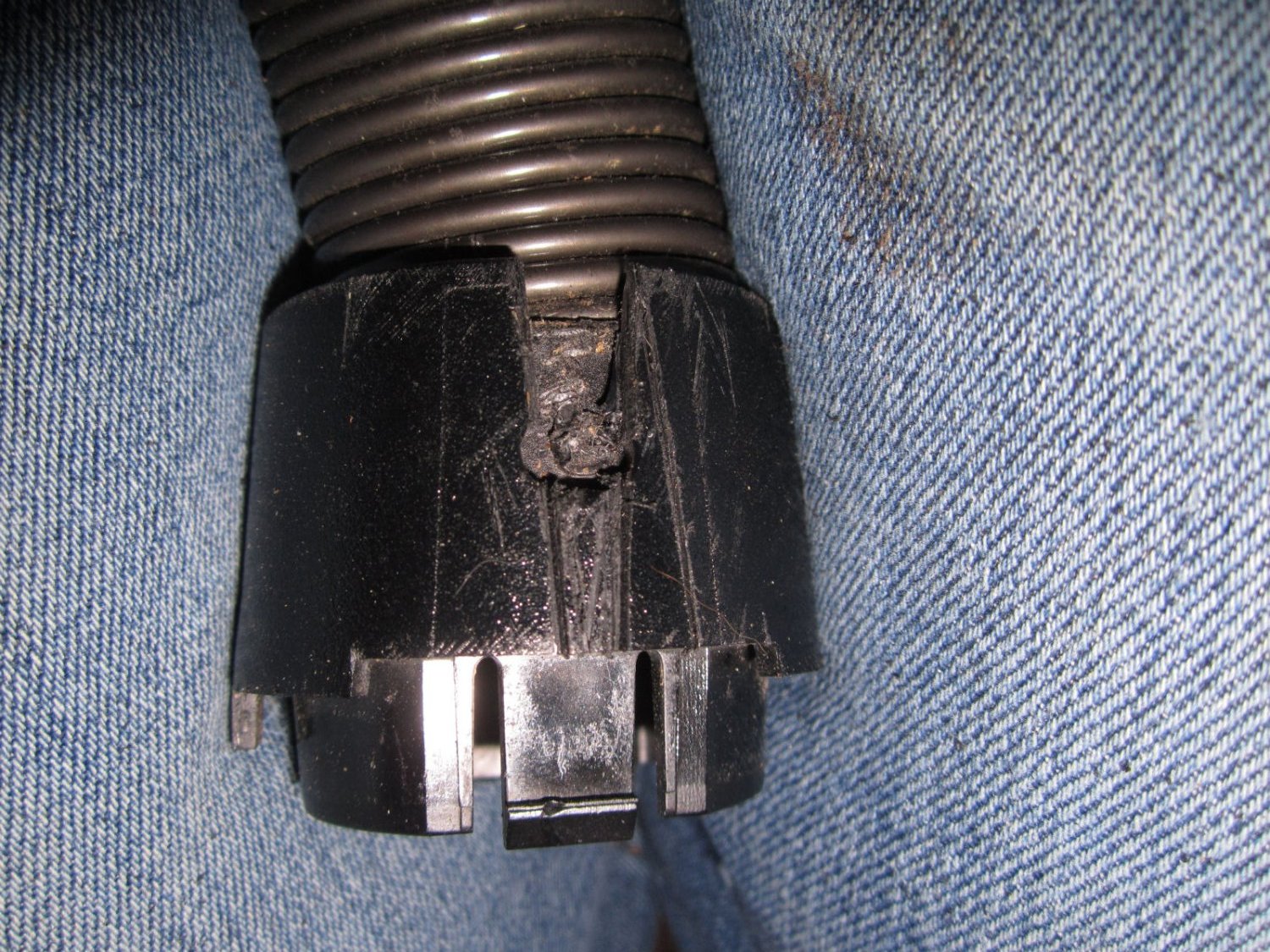
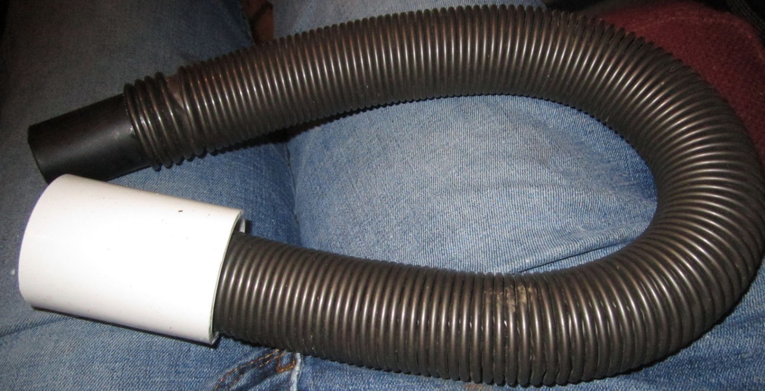
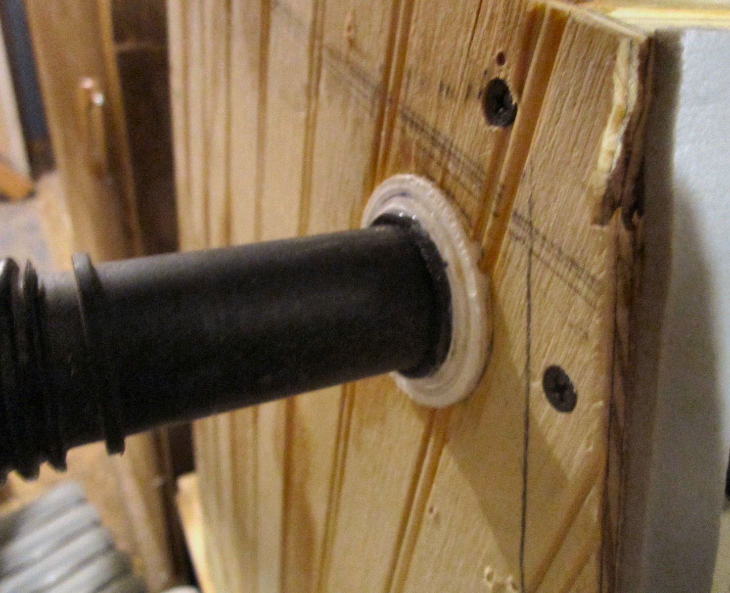
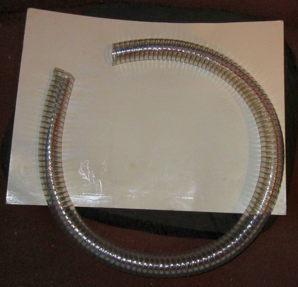
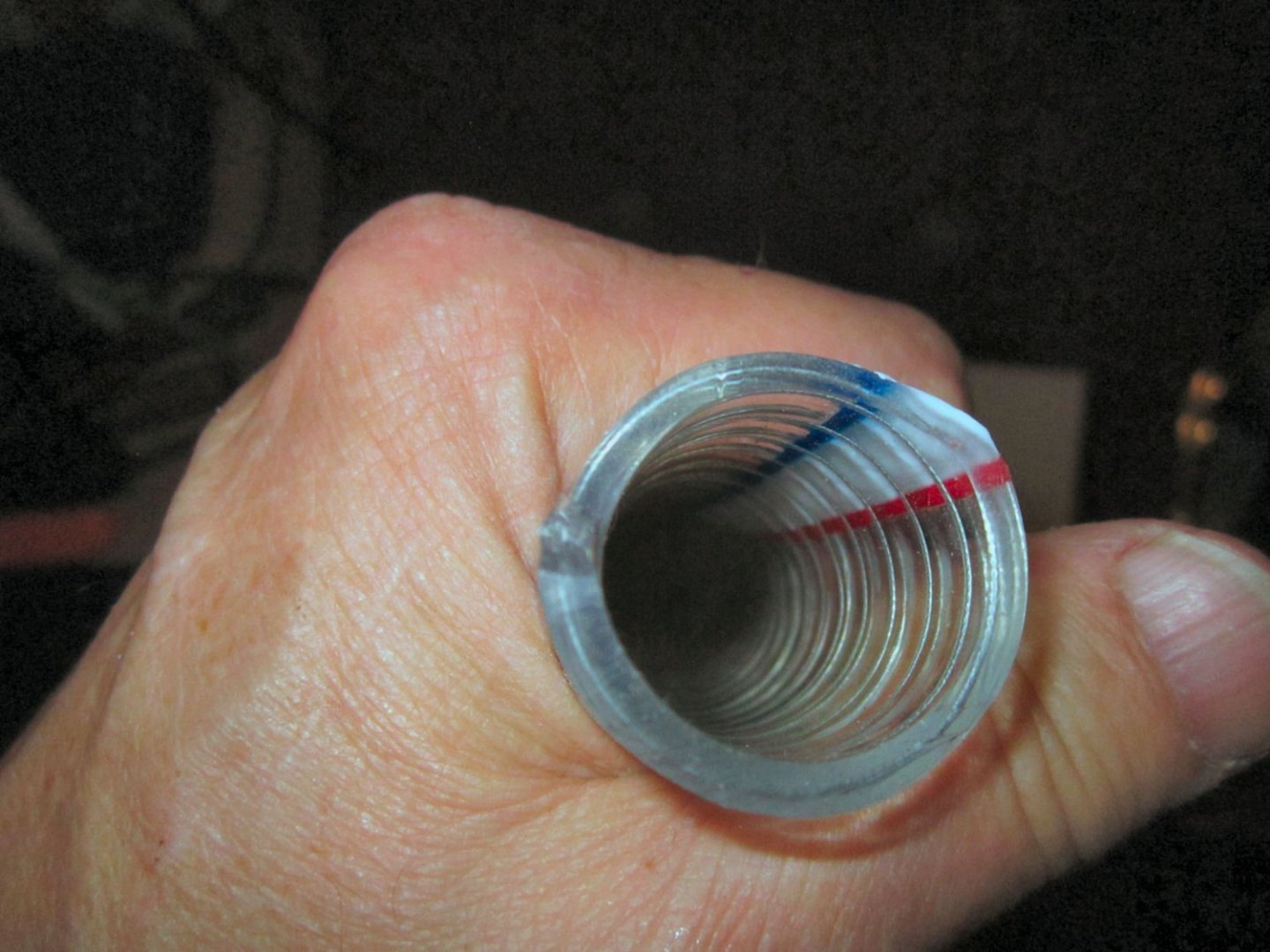
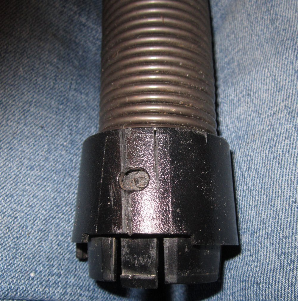
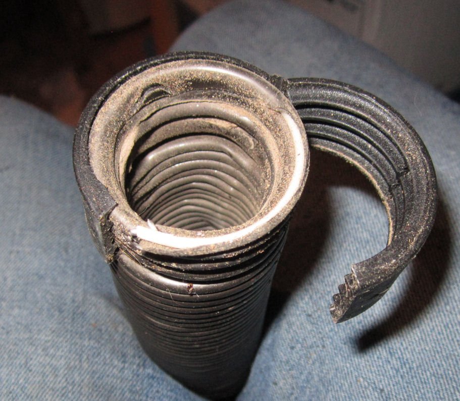
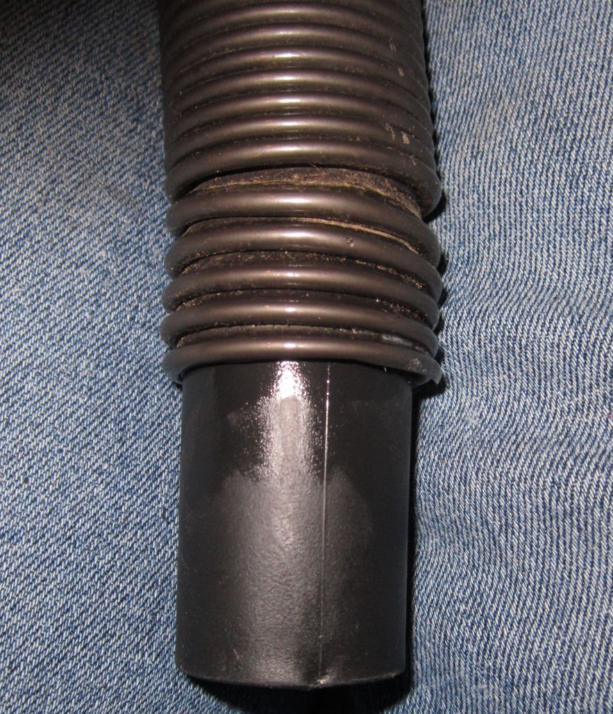
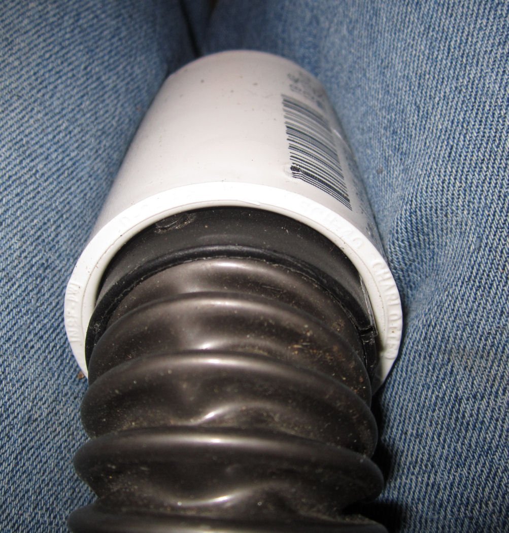
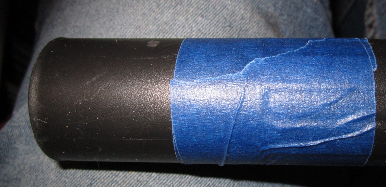
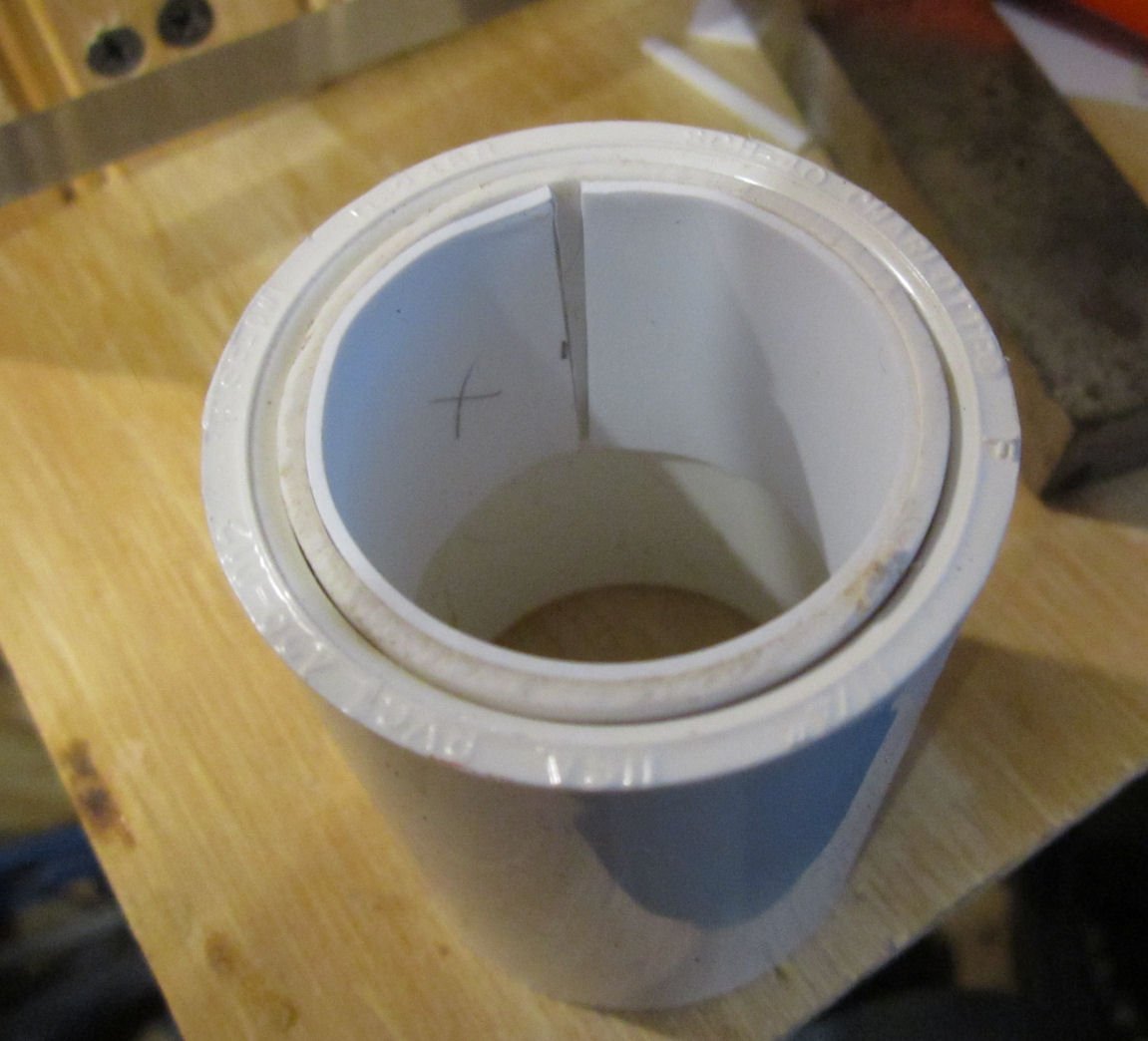
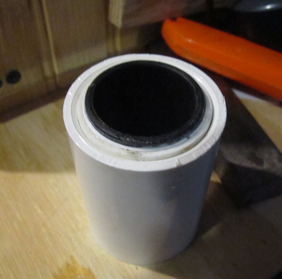
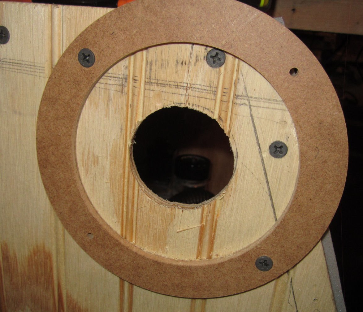
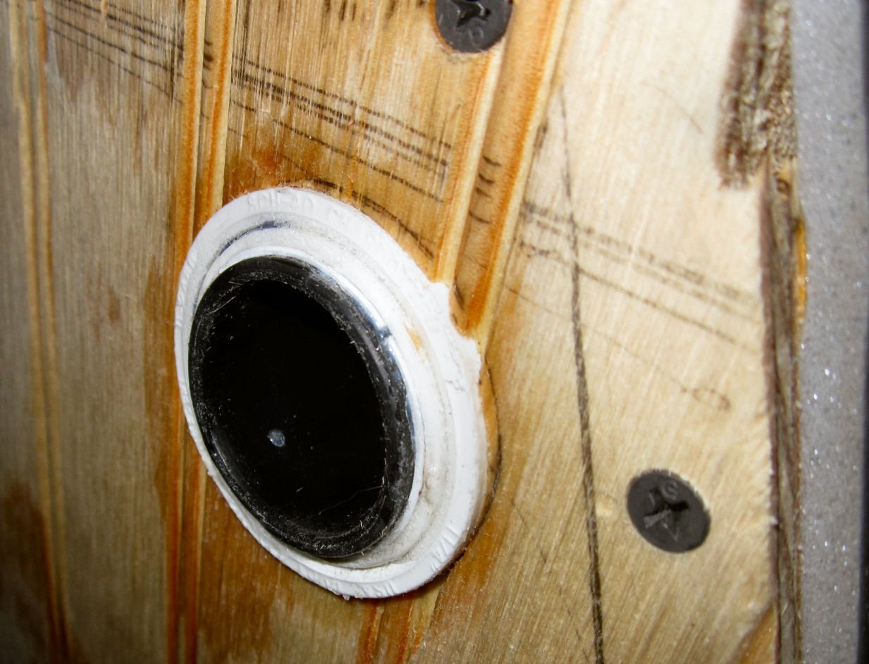
Part 025 – The Vacuum System! Finally! I bought some 1 ¼” OD Vacuum hose on-line. Fail, the hose had 1/8” thick walls, and while vinyl was way too stiff! Our upright vacuum did not have much suction, so I convinced my wife to let me scavenge the hose from it. After much work, and some breaking of parts, I managed to separate the hose from the base. The wand end was too long to fit inside the enclosure, and the other end had a large fitting on it. I had to cut two slots in both fittings to free the two pins locking the hose to the fittings. This left me with the hose with a removable hinged clamp on each end. Now the fun began! The hose was 1 ¼” ID, so it would not fit in or over the dust shoe connector, which is setup for either 1 ¼” OD or 1 ½” ID hose. I sacrificed one of the straight hose sections on my shop vacuum (1 ¼” OD) and forced the tip section into one end of the hose. There was not room to use the clamp, so I wicked in thin CA to glue the tip in place. The other end of the hose with the clamp attached just pushed tightly into a 1 ¼” PVC water pipe coupler (the coupler is a little over 1 ½” ID). The coupler keeps the clamp pressed tightly closed. Then the next problem came up. I had purchased a length of 1 ¼” PVC pipe, figuring that the shop vacuum tip that fit nicely into the 1 ¼” ID dust shoe hole, would also fit nicely into the 1 ¼” ID pipe. Nope! The pipe is actually about 0.010” smaller in diameter than the 1 ¼” nominal size! Looking around I still had the rest of that straight shop vacuum section, with the flared end that, naturally, did fit the flexible shop vacuum hose, and a section of 1 ¼” thin wall pipe (this has a wall thickness about ½ that of the standard pipe). The thin wall pipe fits the coupler, but the flared section was slightly smaller than the ID of this pipe. So I had to fill in the gap. I cut the flare off, using a piece of tape to guide the cut. Then I cut a strip of 0.40” styrene to fit inside the thinwall section. I used a heat gun to soften the strip, so I could bend it to fit. Now the flair fit with a light push fit. I use thin CA to wick into the joints between the parts. When that had hardened, I ran a bead of thick CA to seal both the exposed end, and along the inside seam, to seal the gaps. Now I had a strong connection for the shop vacuum hose, and a removable tight sliding fit to the other vacuum’s hose on the opposite end of the coupling. I cut new centering jigs to fit the OD of the coupler, and used them to position the outer cutting guide on the enclosure. I positioned it near the top front of the left side of the enclosure, as this was in line with the dust shoe fitting, thus keeping it away from the X/Z-Axis assembly. I once again used my Dremel with the router attachment, and a 1/8” SainSmart bit to cut the hole. To determine the proper length for the internal hose, I set the spindle to the Home position, and using a spare 1 ¼” coupling I put the tip into the dust shoe, and fed the hose through the coupler. I tried various lengths, until the hose was just stretched when the spindle was Homed, but not laying on the bed when it was at the far left of the machine. I marked it and cut down the hose. The fit between the modified coupler and the enclosure was tight, so I forced it in until the end was flush with the outside of the wall, and used thin CA to wick in, and glue it in place. This left the rest of the coupler inside, to add some horizontal support for the hose. This is a picture of the shop vacuum hose fitted to the outside. Here is a picture of the finished vacuum assembly. With the vacuum assembly completed, I was able to reinstalled the door and the window, and the enclosure is finished, for now. I may install a pulley system to raise the enclosure up off the bench, with a removable shelf section to support it when raised, but I have not decided yet. I also need to add interior lighting. I also have to install some sort of support for the door when it is open, and magnetic fasteners to hold the front and back doors down on the weather stripping. I may also mount a computer style 120 Volt fan over the inlet filter, to insure cooling air for the spindle, when I’m not using the vacuum. There is enough room in the front to store the boxes I have that hold the bits, and other relevant stuff, when the router is not in use.


-
Ancient anchor found in Yucatan.
thibaultron replied to Eugenio Treviño's topic in Nautical/Naval History
Well medieval, is better than highevil, lower class demon and all. Though there could be some philosophical discussion about whether an anchor could really be evil or good. Though, if it is not holding while you are on a lee shore, during a storm, most sailers would tend toward "Evil". -
Well, "I pulled the trigger" and ordered an AnyCubic 4K 3D resin printer! I have a question about ventilation for it. I know it needs to be used in a "Well ventilated area", which my shop is not. The shop is well sealed, as I have to use electric heaters, and window AC units, so I can't afford to be pulling in a lot of different temperature outside air in. My question is can I put in an enclosed air system in, using outside air just to an enclosure that is then vented back outside? Is the resin greatly affected by varying air temperatures, and humidity? I'm thinking an enclosure for the printer, a hose from outside air for the inlet, and a hose to the outside for discharge, with a 120 Volt 4" computer type fan at the discharge end to pull air through the system.
-
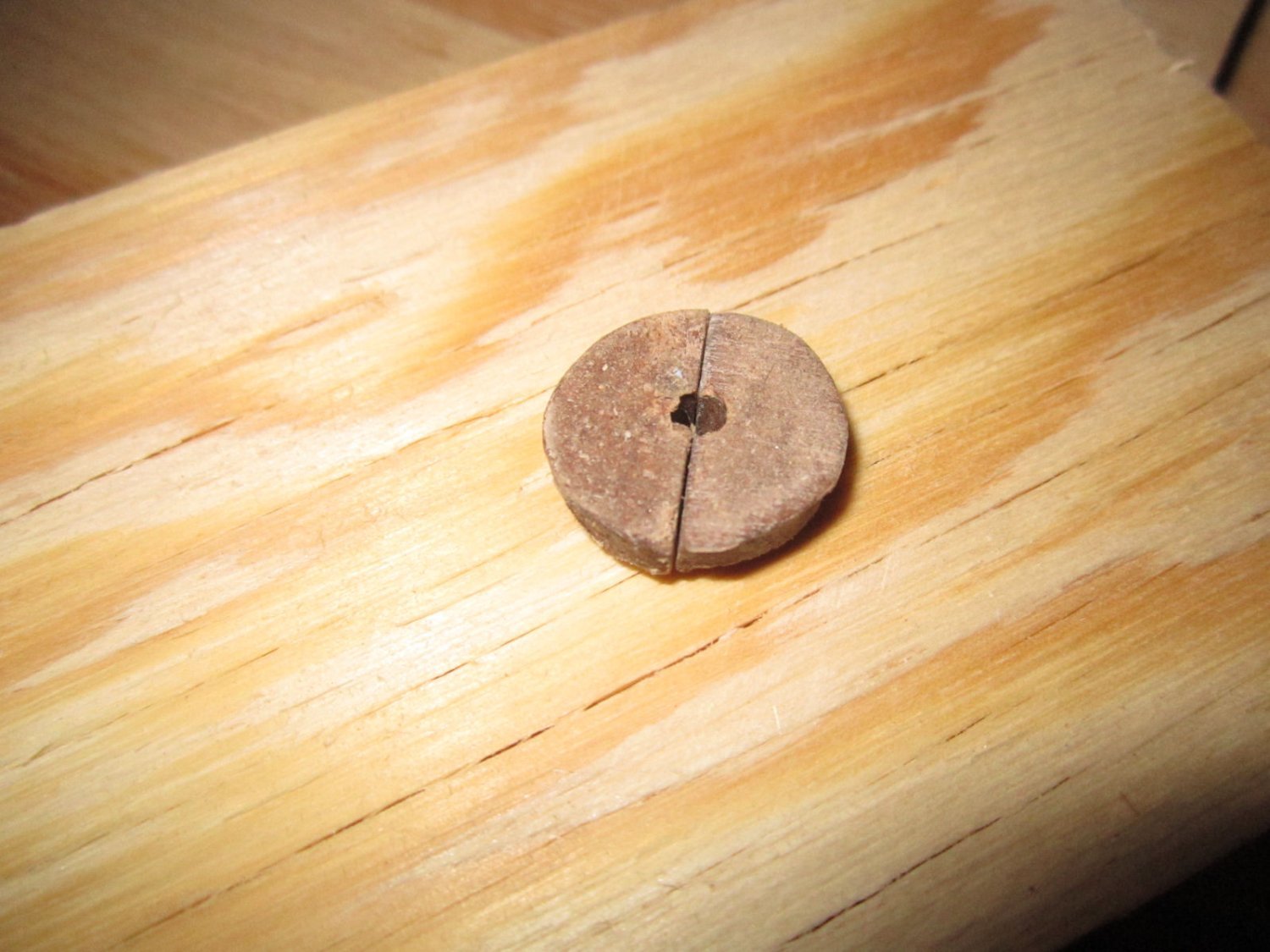
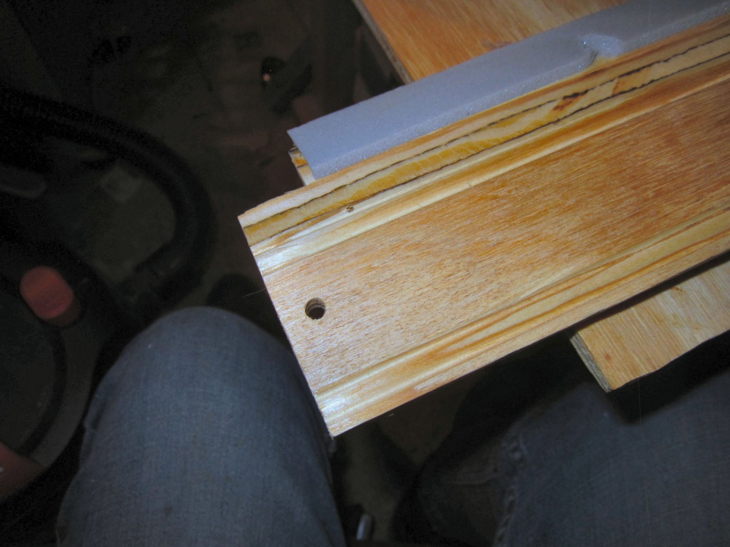
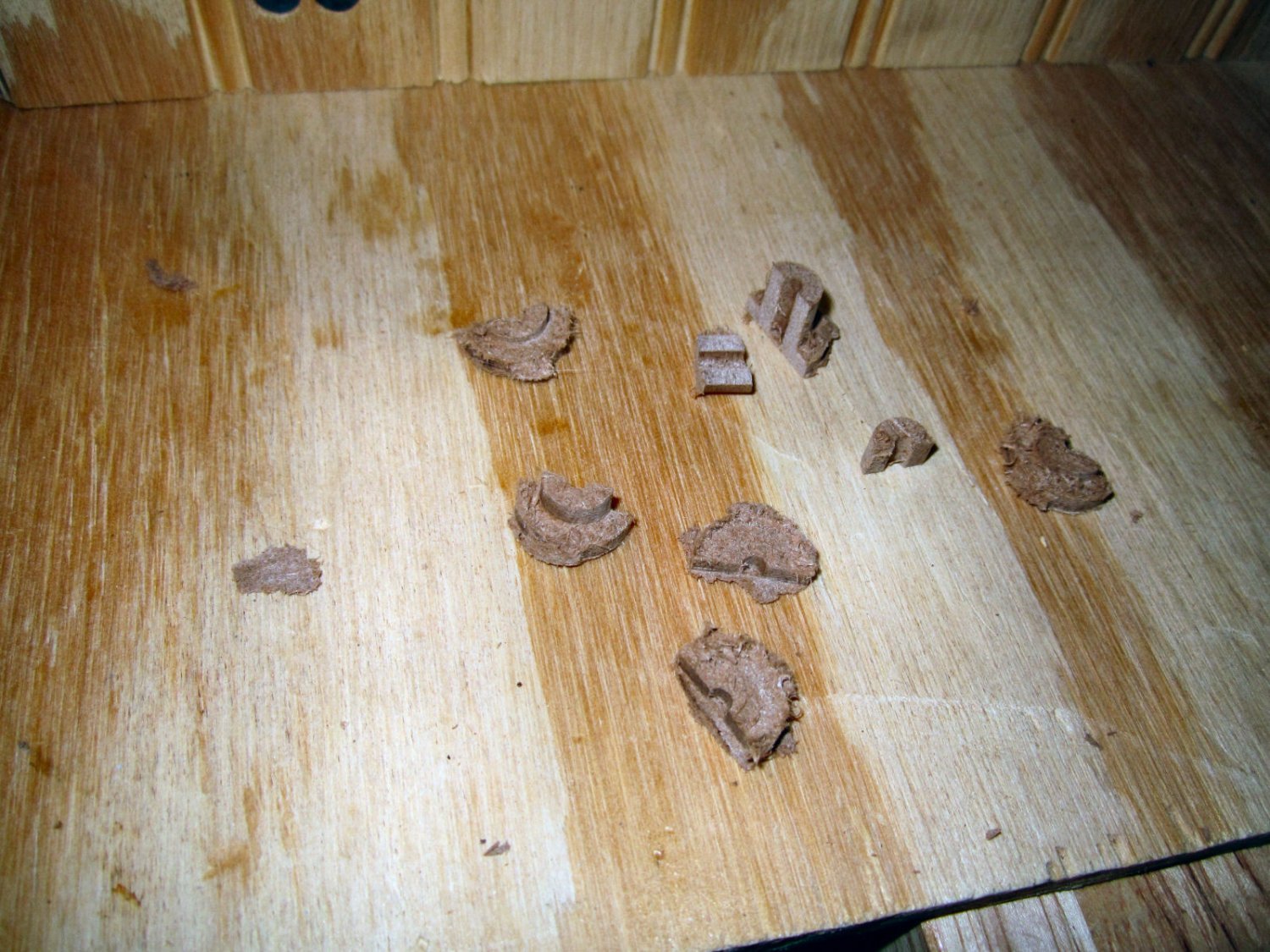
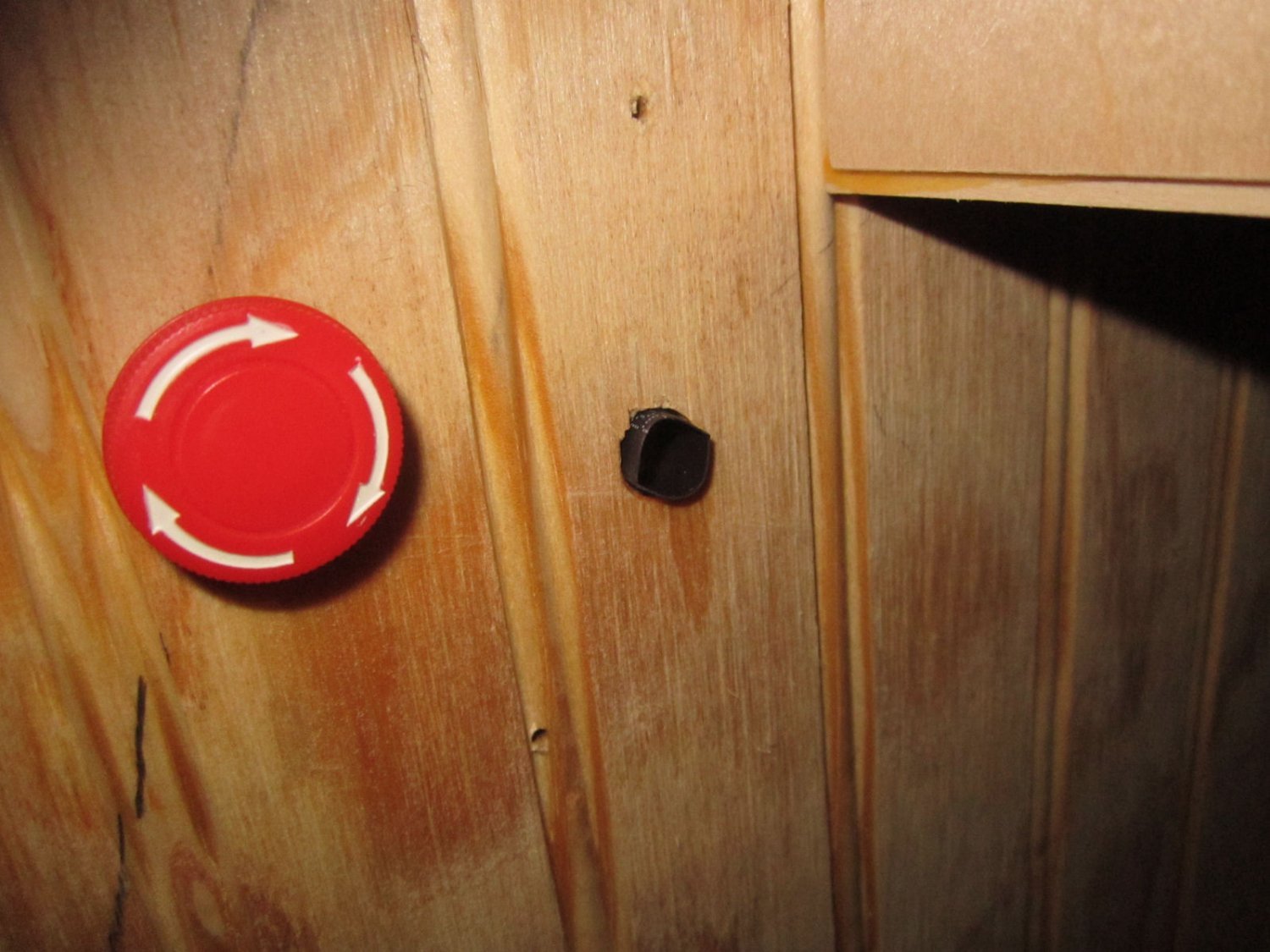
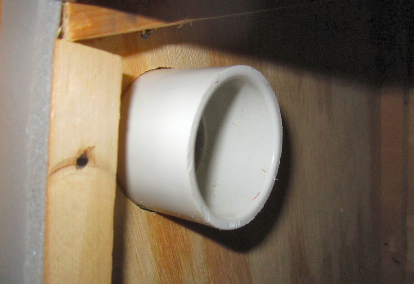
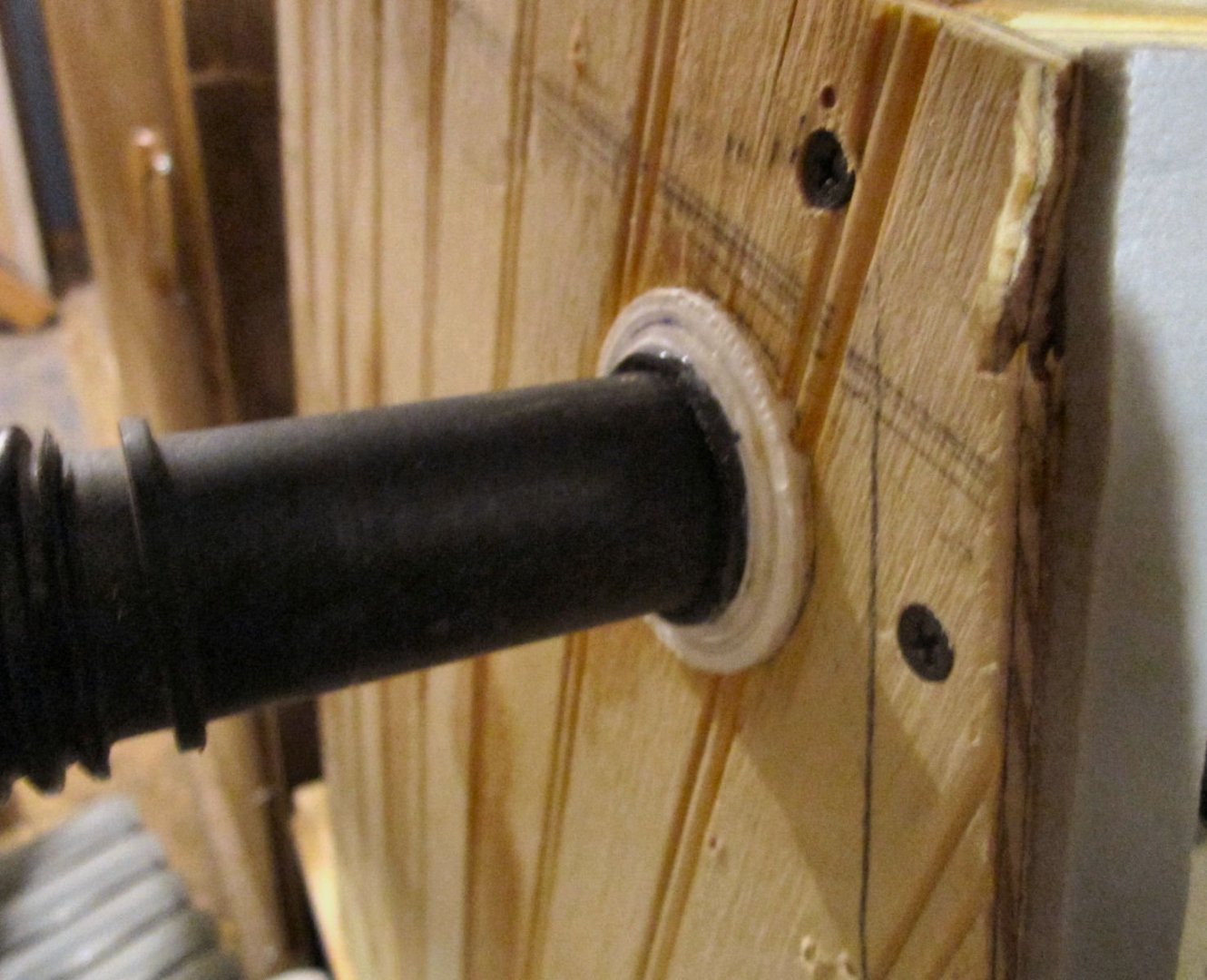
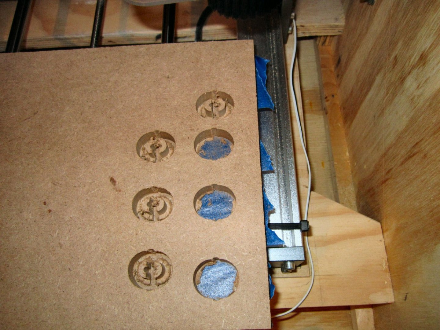
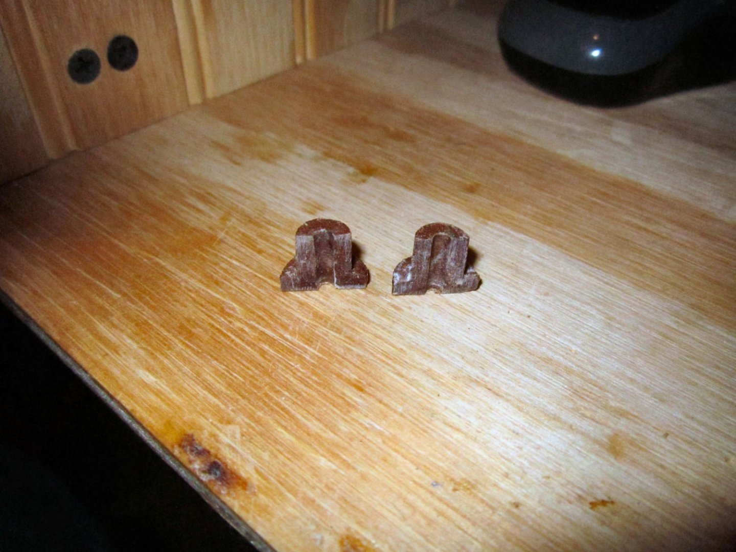
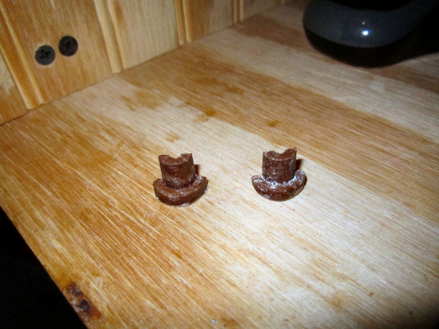
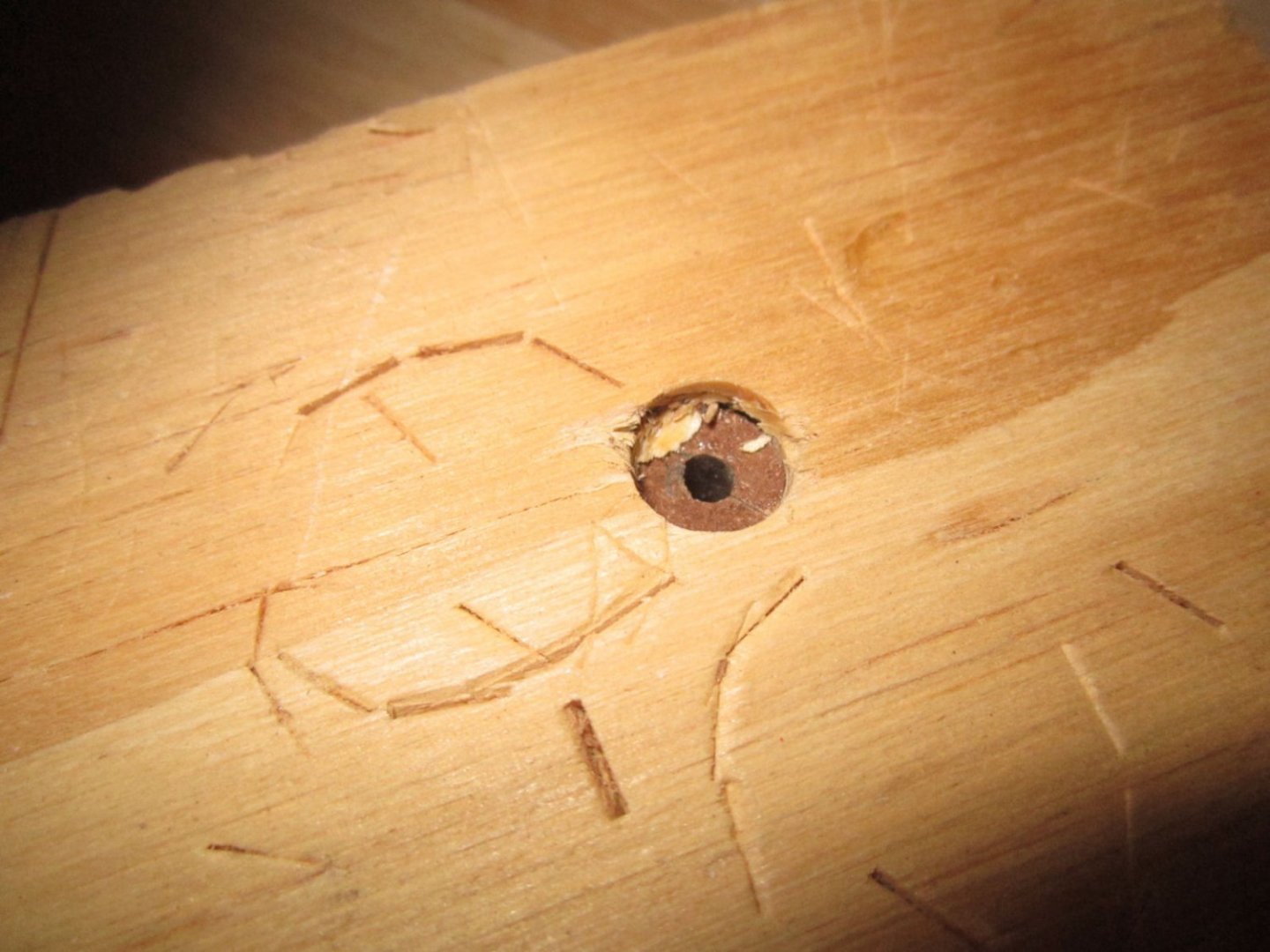
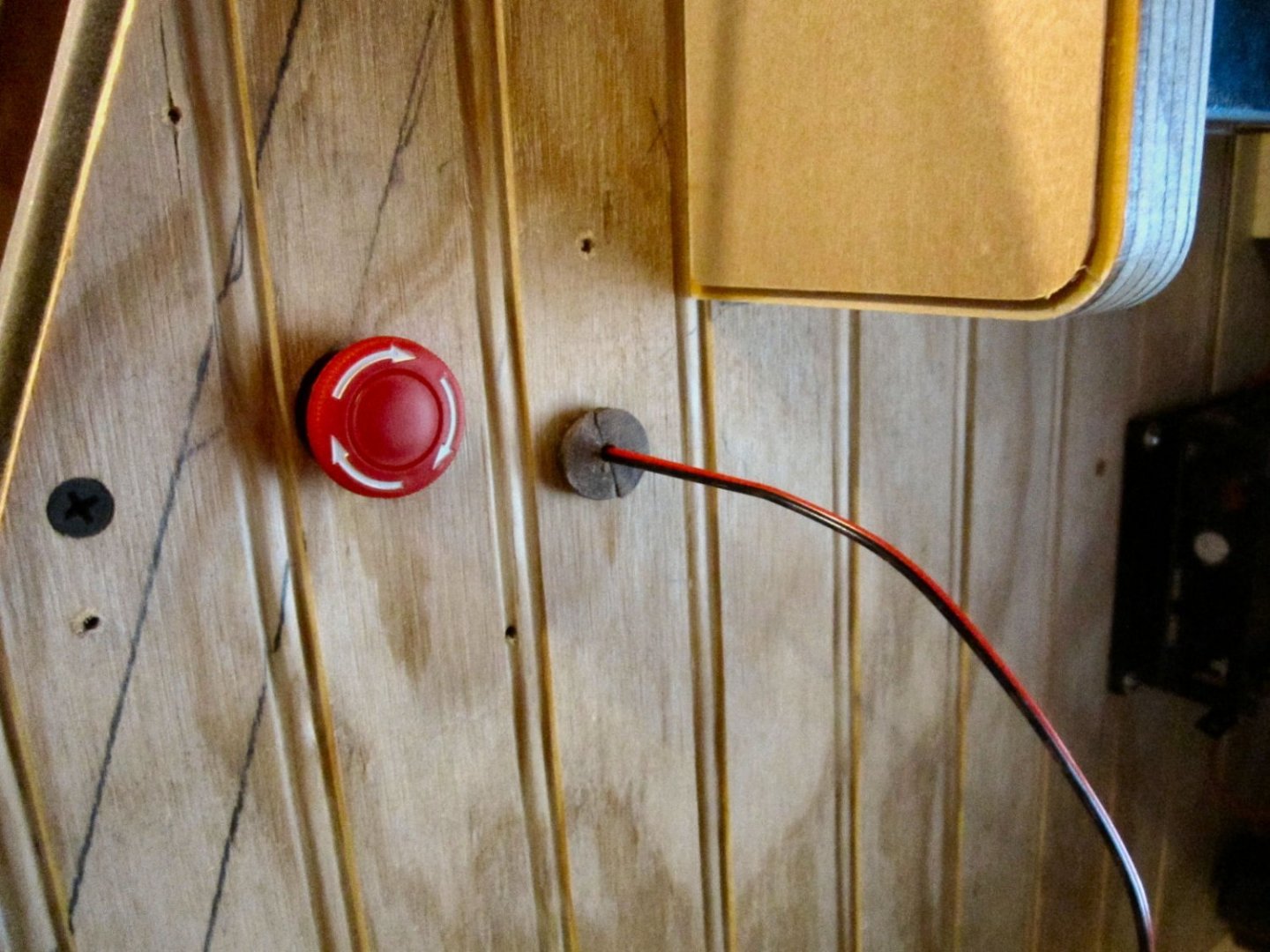
Part 024 – The E-Stop Wire Plug, Continued In the last part, I showed my failed attempt to cut out a plug for the hole I ran the E-Stop Button wires out. The design. The first results. I changed the cutting order so the slot for the inner hole, and the one that separates the two halves was cut first, instead of last. I thought maybe the separating cuts were stressing the parts. The same failure occurred. Next I thought slowing the cutting travel speed down might work. I changed the speed from 13mm/sec to the Carveco default of 7mm/sec. That worked much better! Out of 4 attempts (8 halve pieces), I got 5 good halves. The picture below seems to show all the pieces coming out, but 3 broke while I was removing them. To strengthen the good pieces, I coated them with thin CA, while they were held in place on a piece of blue tape. The coating increased the dimensions slightly, but they still fit in the hole, and tightly now. The white “Powder” in the pictures is the CA after I sprayed it with the accelerator. CA tends to do this, but I did not want to wait for the CA puddles to, maybe, set. A little sanding removed the roughness. Because the CA also reduced the diameter of the center hole, I pushed the plug into a 3/8” hole in some scrap, and redrilled the hole to 1/8”. I repeated this for the second good plug, and stored it away for future need. Here is a picture of the plug installed. After I had finished the plugs, SpindleJockey, who does CNC all the time, suggested the following bridge tab configuration. I’ll file that away for future reference!


-
Thank you for the suggestions. I managed to get two good sets out of four sets by reducing the travel speed from 700mm/min to 240mm/min, in MDF. I then coated the good pieces with thin CA to reinforce them, that helped greatly.
-
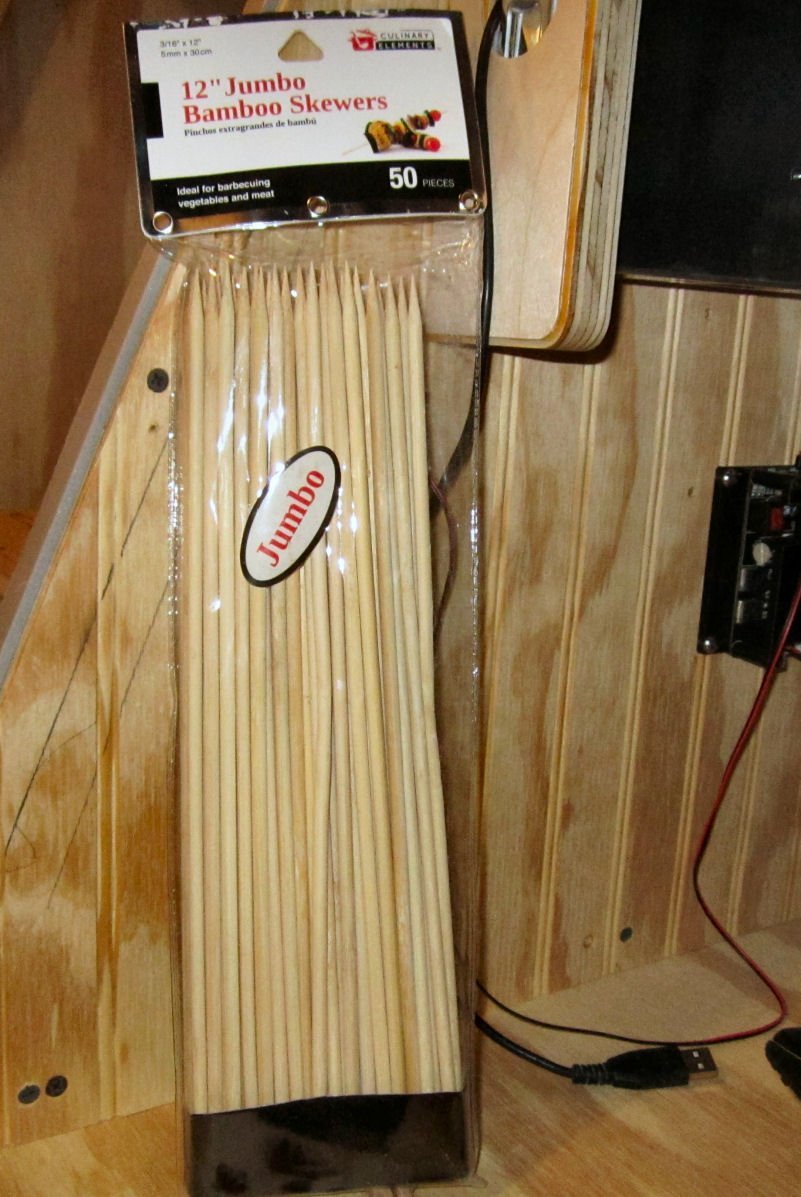
Part 023 – Miscellaneous I decided not to hinge the front piece. The magnets were holding it well, with just the temporary nails for guides. I bought some bamboo skewers, that ended up being about 3/16” in diameter. I clamped one side of the front and removed that nail, then drilled 3/16” using the nail hole as a guide. Next I drilled the front 13/64” for a nice sliding fit on the dowel, as well as just a very short depth into the enclosure, to guide the insertion of the dowel. I glued the end of the dowel and drove it in with a hammer after cutting off the point. After cleaning up the excess glue and allowing it to dry about a half hour I reinstalled the front, and repeated the process for the other side. I cut off the extra dowel and sanded it flush, then slightly rounded the exposed end. I designed a plug for the E-Stop wire, but the router failed in cutting one in either 13mm MDF, or regular ½” plywood. In six attempts (3 in each) the parts broke before the cuts were completed, and I was unable to get two good halves. The body of the plug is 3/8” diameter , once the two halves are fitted, with a 1/8” center hole. So, for now, I put a piece of 3/8” heat shrink tubing in the hole, to keep the wire from chaffing. I will try again, reducing the cutting traverse speed, or I may try it in a thick piece of plastic cutting board I have. I’ve used pieces of this cutting board to make new sheaves for the rotted ones in the pulleys on a 23’ sailboat, and the rollers for the sliding doors in my shop, so it is quite a durable plastic. I also cut a second center for the vacuum jig, with a 1 ¾” hole in the center to allow me to place the vacuum hose hole to clear the corner battens. I still have not decided on the final location for the hole, or the exact way I’m going to mount the hose to the enclosure. I’ll detail that later. My present shop vac has a 1 ¼” OD hose, so I need an adapter to mate it with the 1 ½” ID hose I want to use inside the enclosure. I’m going to use the 1 ½” hose, in case I get a larger vacuum, in the future.