HOLIDAY DONATION DRIVE - SUPPORT MSW - DO YOUR PART TO KEEP THIS GREAT FORUM GOING! (89 donations so far out of 49,000 members - C'mon guys!)
×


thibaultron
-
Posts
2,944 -
Joined
-
Last visited
Content Type
Profiles
Forums
Gallery
Events
Everything posted by thibaultron
-
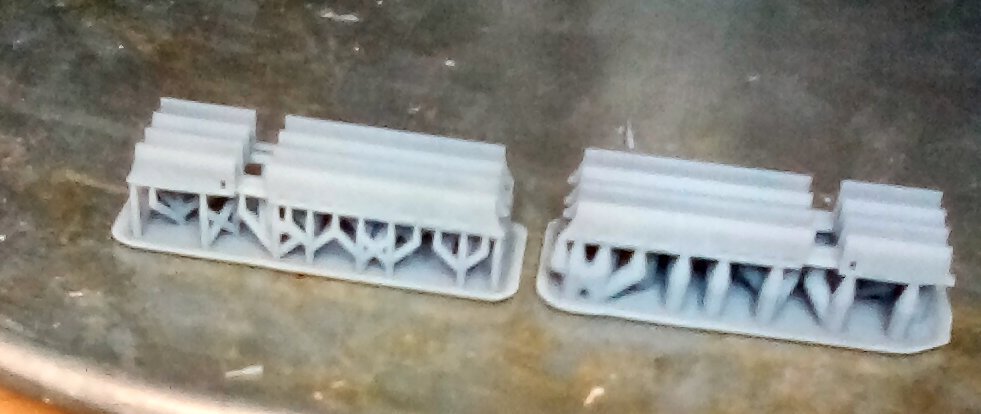
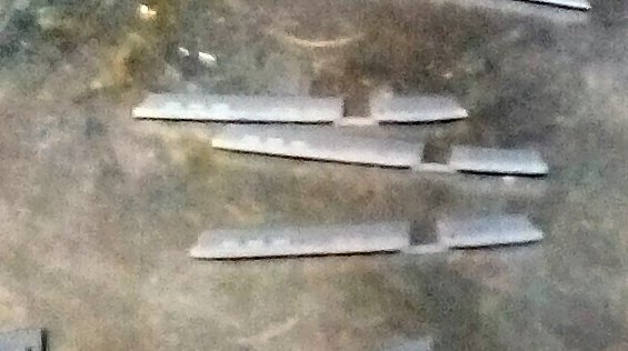
Well the second print of the skirts came out much better! These were done at a 2.75 second exposure, 50um layer height, and 1 minute cure time. Again the pictures are blurry, due to the limitations of my Kindle camera. My phone camera does much better, but a couple of months ago my computer stopped recognizing it, I suspect after one of the MS updates.. Again here is the sliced file Here is the print of both the medium (left) and Heavy (right) support versions. If you look at the tips at the far right, you will notice that bottom of the tip is curved up. I forgot to add supports for the tips at that end. Here is the best I was able to do for a close up of one of the skirts. Trying to hold the part behind my magnifying light and balance a Kindle in front was quite difficult. And finally here is three of the skirts. The other 5 turned out to be in shadow when i looked at the picture on the computer. I will have to slightly modify the final print, as the bar across the two sections broke when I removed the prints from the supports, and I will add the extra supports and tilt the print, to perhaps help with the tip problem. The fact that I forgot to remove the supports before I cured the prints may have added to the bar breaking. All together though I'm pleased with these, they were just test prints. When I go to print the final ones, I will have to use a better resin, this one is to brittle. Probably I'll use Siraya Tech Build, which is a bit more durable. I would like to thank my cat for helping me write this, the blocking of the monitor, and keyboard, as well as the random key hits was enjoyable, Not!

-
The car section I am having problems with, has been checked with Netfab, and passed, and Lychee said it had no errors when I imported it. It is the supported file that Lychee saved as a STL that Lychee is having problems with. I used the Anycubic R_E_R_F file results to get the 2.3 second value, but at 100% light level, I forgot that I had reduced it to 80% to save on wear of the LEDs and LCD screen. These are small parts (2" long by .05" thick each), so I didn't angle them, if the next prints fail, I'll try that.
-
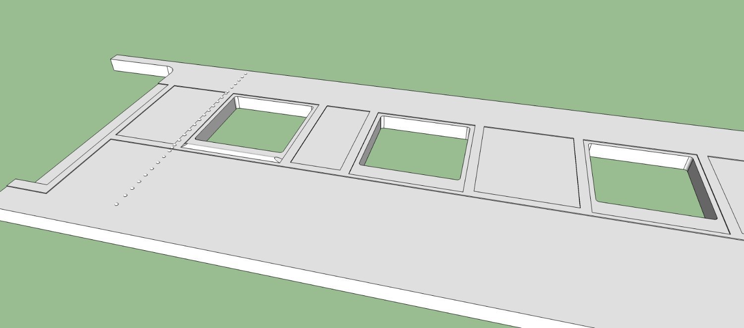
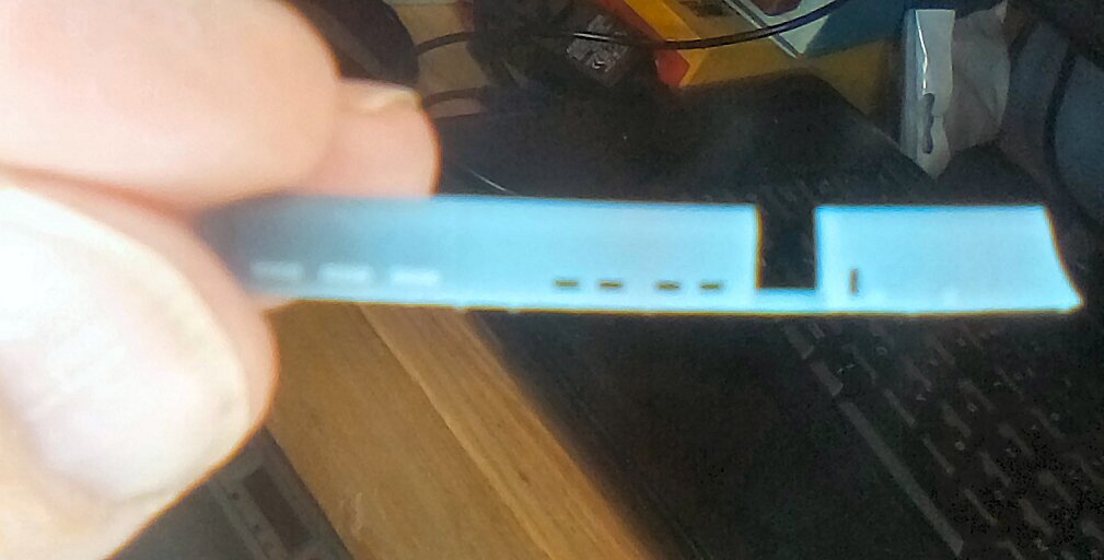
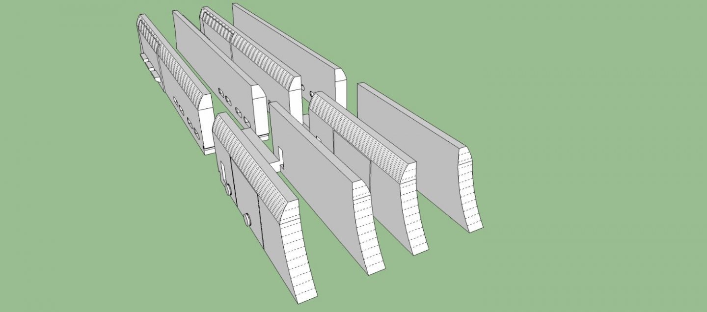
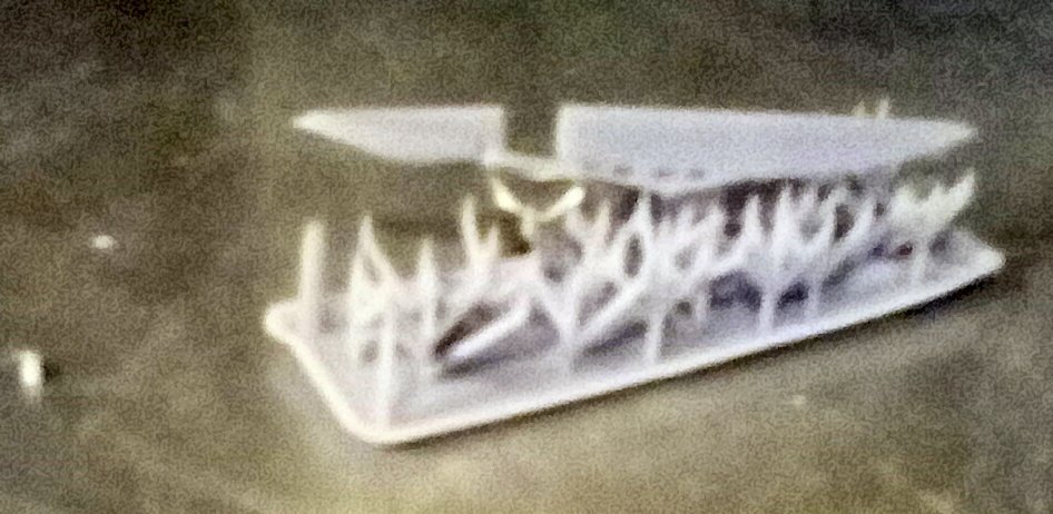
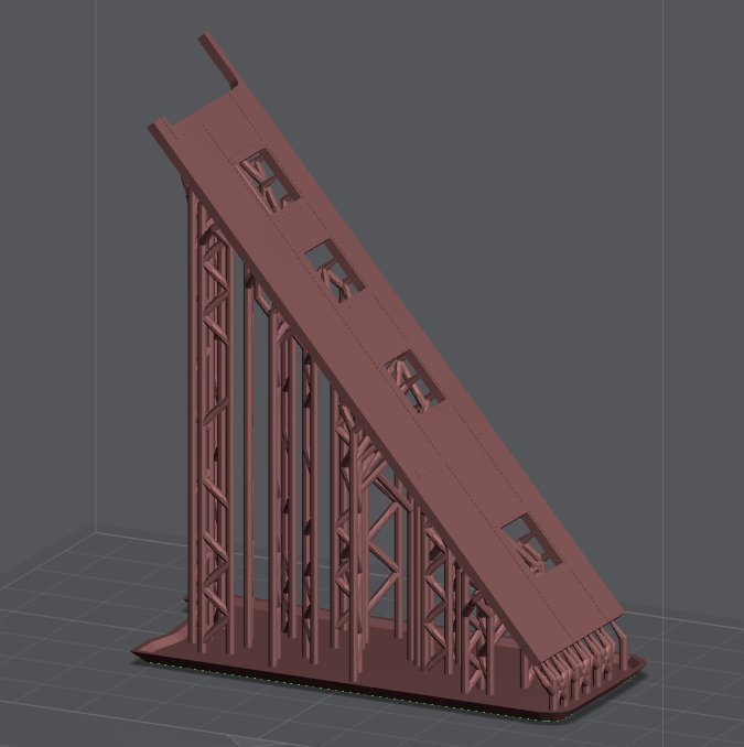
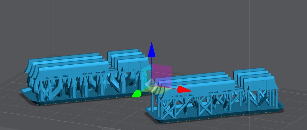
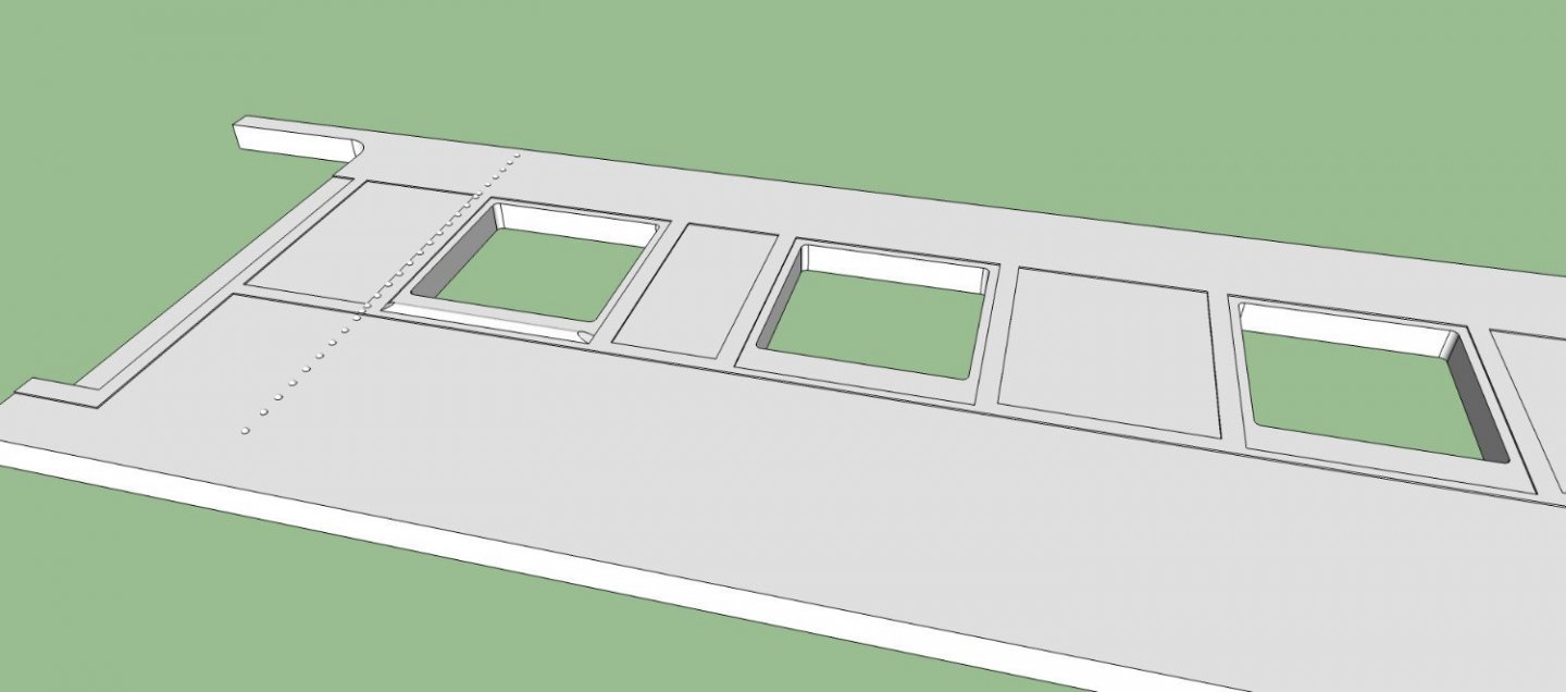
Well, tried my first "real" print today. Fail! I think there were a couple problems. 1. This is the first file I sliced a month or so ago, and I'm not sure I even got the supports close, I think I modified them to reduce the diameter of the supports where they intersect the print, and they were too weak. 2. I forgot I had reduced the light output from the factory 100% to 80%, and I ran my R_E_R_F print at 100%, so my exposure setting was too low. I re-supported the file using both the default medium, and heavy supports at the first exposure (2.3 seconds), and another file at 2.75 seconds exposure. I'll try the 2.75 first tomorrow, If that is successful I'll retry it at 2.3, just as an interesting test. This is what the print should look like after the supports are removed. This is what printed. Sorry about the blurry picture, I can't find my camera, and my Kindle is really pour at close up photography. The finished print should be about 2+ inches long. This is a screen shot of the Lychee file for the above locomotive skirts with both the medium and heavy supports. I'm going to print both at the same time. Once I get a good print, the next one is a short section of the side of the HO passenger car I'm designing. I just want to see if the rivets, and the various layers of steel on the side come out alright, as well as determining if I have to adjust for the resin changing size as it cures. I'd hate to lay out a few hundred rivets, only to find out I need to make them slightly larger to print well! Here is a picture of the section of car side. The rivets are a scale HO 1" in diameter. The various layers are a scale 1/4 inch thick, and one window (left one) has the half round sill. The whole side is a scale 5 inches thick., and the section is 30 scale feet long. Here is the Lychee file for it. This will also test how smooth the surface of the side is, as I used the ArcTan spreadsheet program to calculate the angle (49.4 deg) for a 35um layer height. I'm also running into a problem with this file in Lychee. I import the STL for the section, it says there are no errors. I add the supports, and it is happy. I save the sliced print file, and it is happy. I save the STL of the supported part, and it is happy. Then when I import the supported STL, it says there are errors! If I tell it to fix the errors, it crashes! Then it keeps restarting Lychee, and crashing in cycles. I have to restart the computer to get it to stop! The print is in red, because I imported it for this screen shot.
-
Joe, you are not wrong, but like any material you use in a hobby, learning the materials is part of the process, be it wood plastic, resin, etc.
-
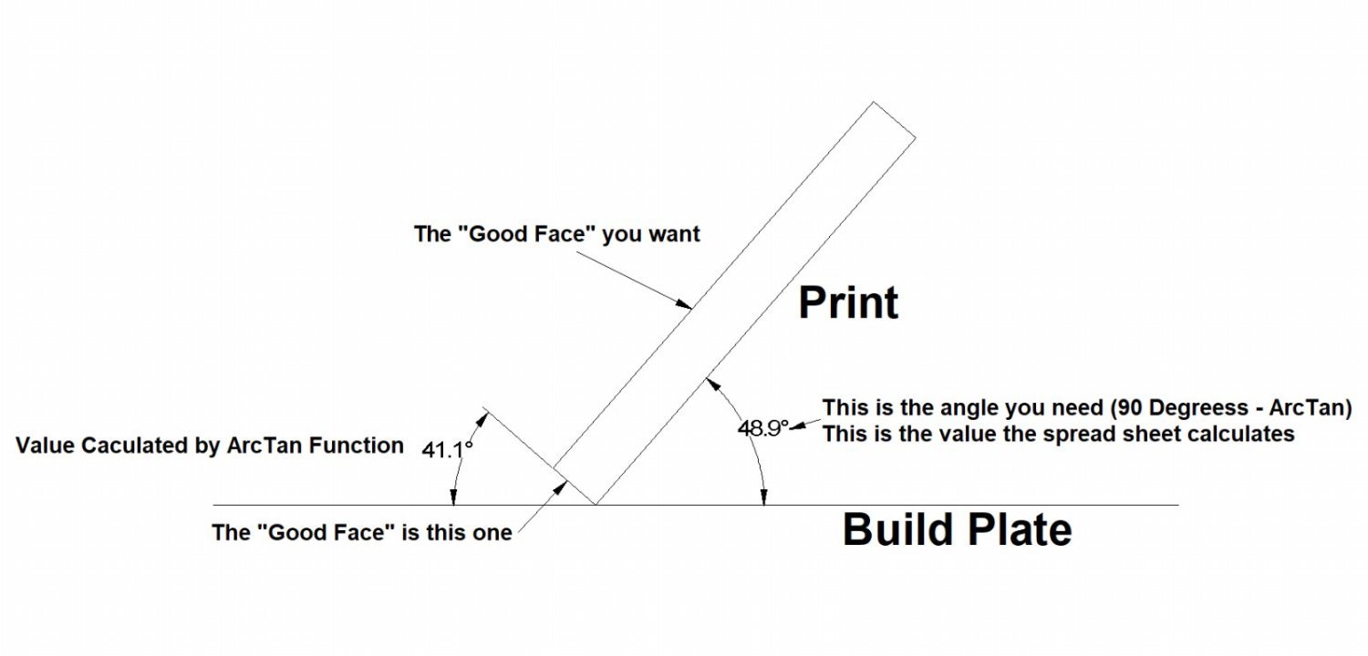
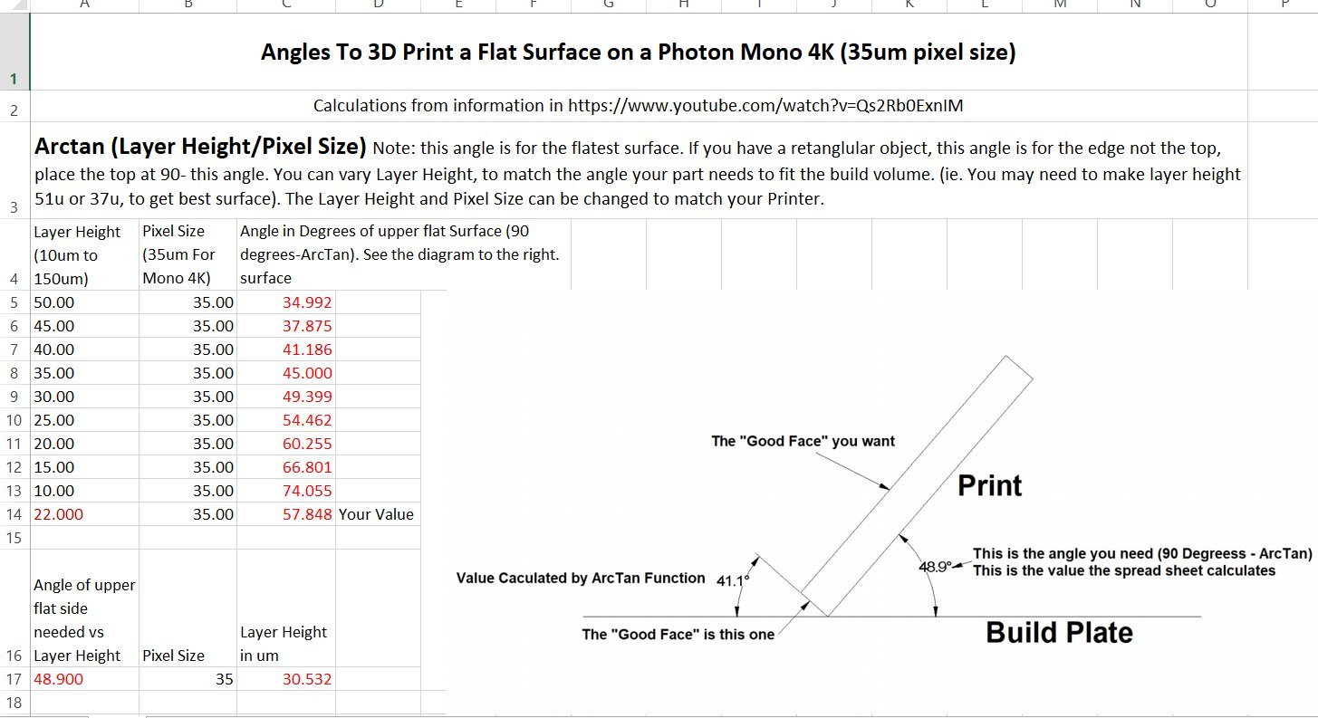
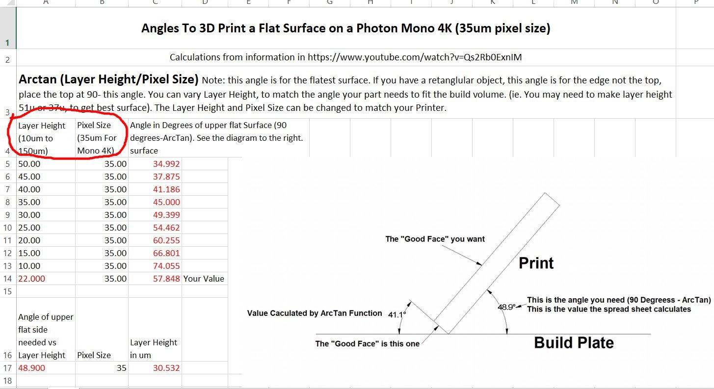
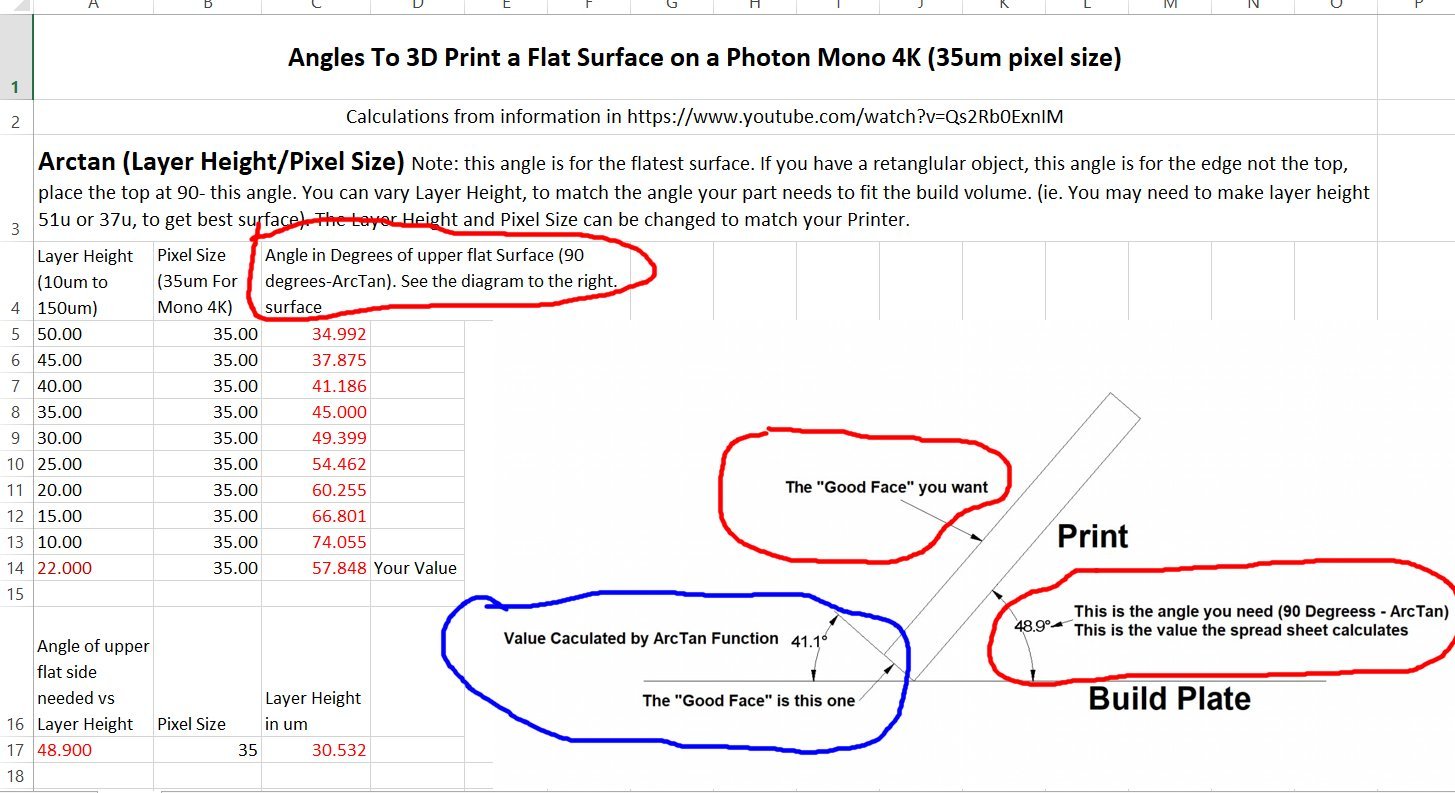
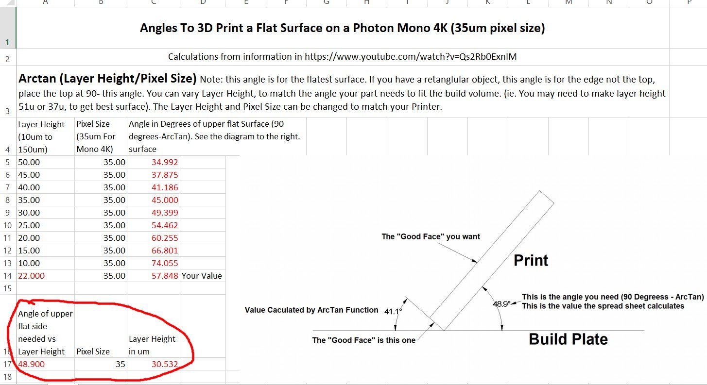
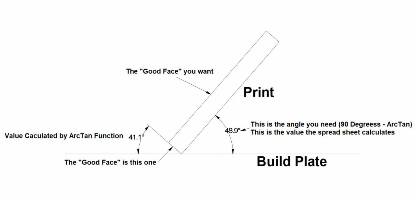
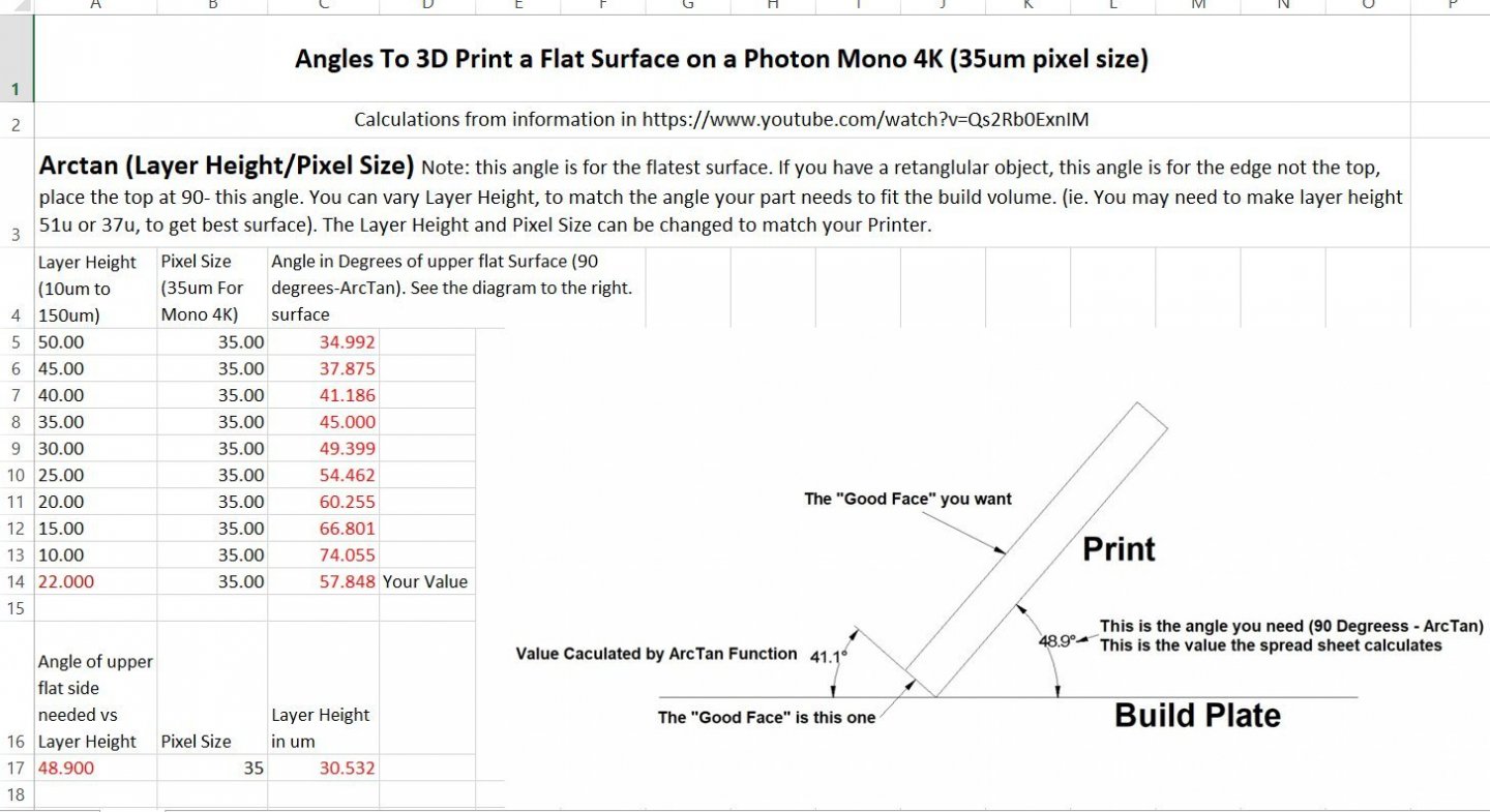
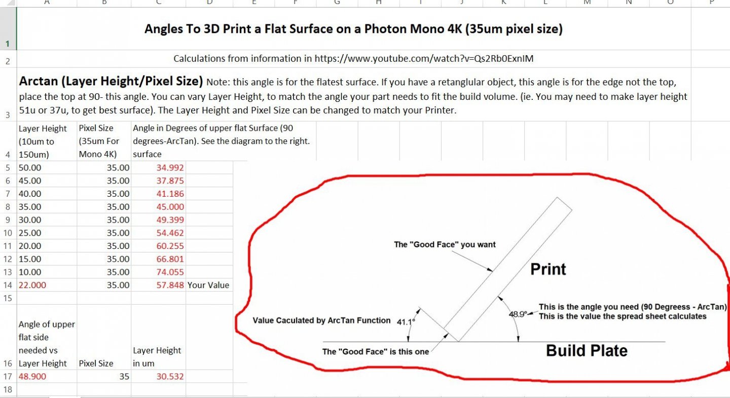
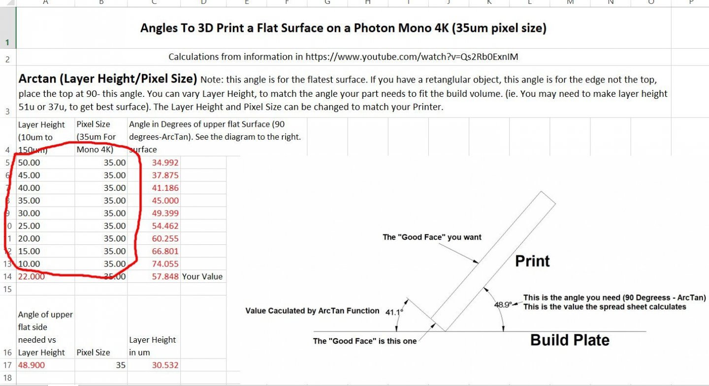
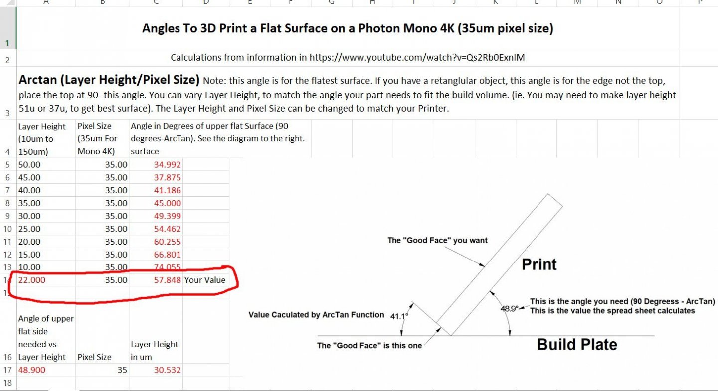
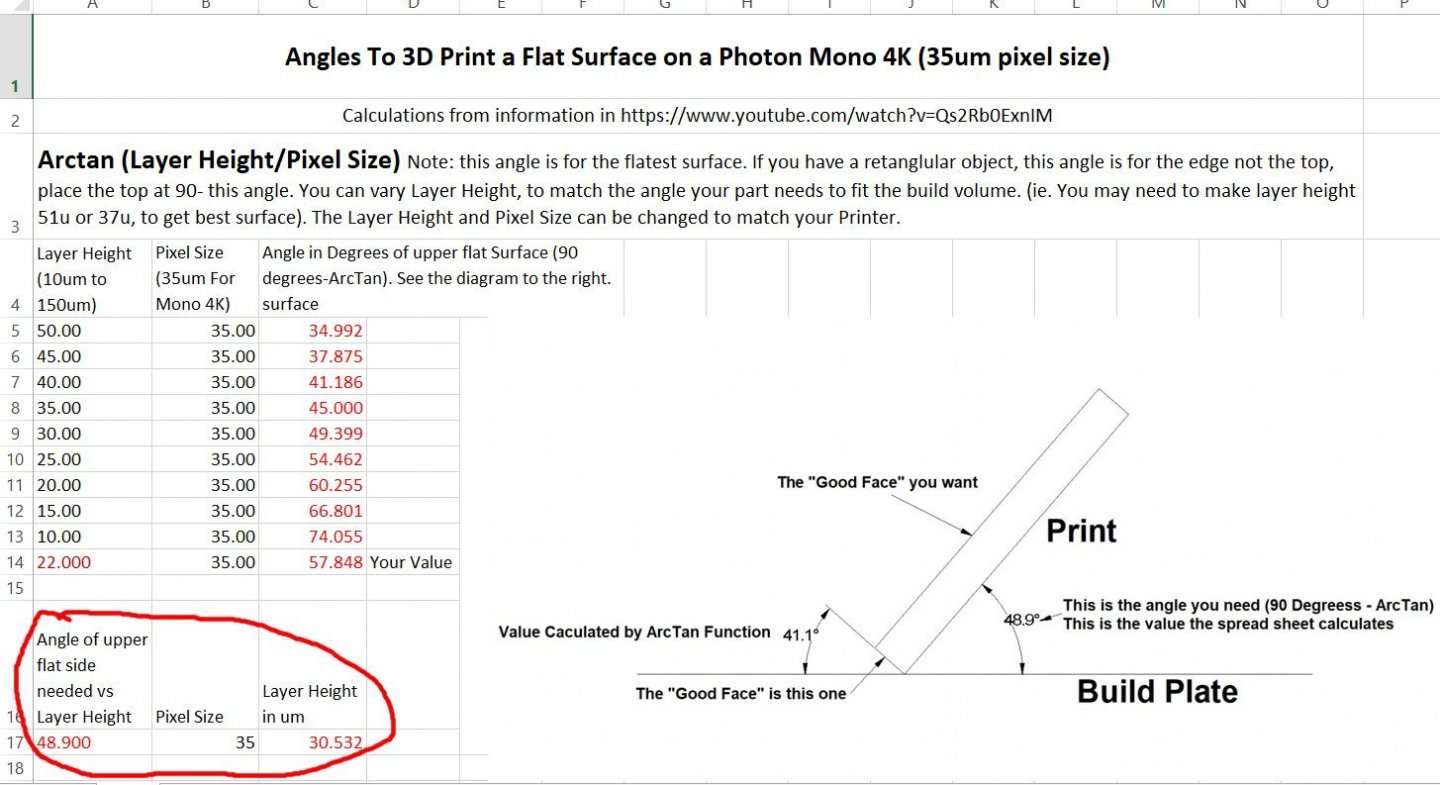
After watching the video about how to calculate the best angle for a print to be placed at, to get a smooth surface, I created a spreadsheet to do the calculations. This means I don’t have to rewatch the video every time I want to find the angle! The formula involves finding the angle of the Arctangent of the layer height/pixel height. Don’t run away yet, I know trigonometry hurts, but it will be worth it! The video is at: https://www.youtube.com/watch?v=Qs2Rb0ExnIM Here is a diagram of the calculations The video explains it more but the diagram sums it up. I developed a spreadsheet to do the calculations. This is a screen shot of the spreadsheet. As you can see I pasted a copy of the diagram into the spreadsheet to remind me of what I’m looking for. The first section takes the Layer Height and Pixel Size values and uses them to calculate the (90 degrees - ArcTan) value that is what you need to rotate your model to, in your Slicing Software. In the spreadsheet I’ve entered the pixel size for my Anycubic Mono 4k printer, the Sonic 4K uses the same pixel size. I found the value by looking at the specifications on the Manufacturer’s site. The Layer Heights I entered are a range of the standard ones for most newer printers. You can replace these values with those of your printer, just be sure not to mix up the pixel and layer values. The last line in this section (with the Red text), is for use if you have some special layer height you need to use. Sometimes you need to place your model at a certain angle to make it fit in the total print volume. For instance, I am designing a model of a specific Santa Fe business car, and a side will just fit diagonally inside the print volume. Therefore I can only print it at a fixed orientation. The second section calculates the Layer Height I need to print this at to get the best surface. You enter the angle in the Red text area, and the spreadsheet calculates the correct layer height to use. In the example I used the angle shown in the diagram. Naturally, by picking one surface to be the best, the others will print with more artifact lines, but at least you can determine which surface is the most important. For example, in either the above video or another the YouTuber used a tank body as an example. He wanted the top to be the smoothest surface, as this is the most visible one. He accepted that the back and front might have a slightly rougher finish. I hope this spreadsheet helps you! General Angle Values For Printing Aflat Surface on a Resin Printer_002.xlsx


-
Does anyone know if we can post an Excel file on the forum? I have developed one to calculate the best angle to print your model at to give the upper surface the smoothest finish, based on a couple of YouTube videos. I would hate to try to explain how to create it for yourself, as it gets into some deep "things" to insert the formulas, into the spreadsheet.
-
 Soak the bow in isopropyl alcohol to lossen the glue, then you can correct the alignment and reglue.
- 63 replies
-
- 4
-

-
- Finished
- Khufus Solar Boat
- (and 1 more)
-
M3 Lee Tank by CDW - Miniart - 1:35 Scale - FINISHED
thibaultron replied to CDW's topic in Non-ship/categorised builds
Could you install the tracks, then the drive gear? -
https://www.boatinternational.com/yachts/news/sailing-yacht-eleonora-e-sinks-in-spain
-
Something "interesting" I found out about Sketchup today, at least mt 2017 version. Well really two but one lead to another. I'm designing an interior for a brass HO passenger car I have. So I designed it to a scale 10 7/8" length on my regular CAD program, and transfered it to SketchUp using an old Pro version I have, just for such activities. I had earlier discovered that when I do this, I use inches in my regular CAD, but when I import the drawing (DWG) into my older version converts it from inches (say 100") to feet (100')! So for this interior, I went ahead and shrank it back to the 10+ inches. Then I started to work with it, SketchUp does not like to use fractions of an inch smaller than 1/16th or 1/32!! This makes generating small parts difficult, you start to run into gainyish issues.! I can manipulate the original I imported, but sometimes trying to generate new "things" causes it ti cought. So from now On I design my stuff Full scale, then shrink it down!
-
Use acid free paper, though I'm sure regular paper would probably be good for 10 or 15 years, before it starts to yellow.
-
I finally go there! I had to Google Naval Academy Museum and go through their menus.
-
For some reason I can't seem to get to it on my computer. Strange, I tried Firefox and Edge.
-
M3 Lee Tank by CDW - Miniart - 1:35 Scale - FINISHED
thibaultron replied to CDW's topic in Non-ship/categorised builds
Yes, leave a way to see all that detail! -
M3 Lee Tank by CDW - Miniart - 1:35 Scale - FINISHED
thibaultron replied to CDW's topic in Non-ship/categorised builds
And they can bury me with it, after the admiral kills me for buying it! -
According to the information I found on the movie, that King Kong was, like the original, supposed to be about 25 feet high, if that helps for scaling.
-
Roger, which ship are you building?
-
I can see a 3D CNC carving of this in my near future.
-
M3 Lee Tank by CDW - Miniart - 1:35 Scale - FINISHED
thibaultron replied to CDW's topic in Non-ship/categorised builds
The Sherman used a radial engine also. If the engine in your kit is as detailed as the illustrations show, you might want to display it next to the tank, rather than hide it inside. -
This was posted on another thread, but I think it fits.
- 488 replies
-
- 22
-
-

-
- Indefatigable
- Vanguard Models
- (and 1 more)
-
Unfortunately, none of the buildings will be tall enough for him to climb.
-
I'll be watching, and thanks for the download link! This is just the type of ship I've been looking for for the pier area of my model railroad! And I love that version as well as the original version of the King Kong movies!
-
1350mm, I'm sorry dear, I thought the catalog said 135mm! Must need new glasses! Why do you have that gleam in your eye, and why are you holding a knife?
- 488 replies
-
- 12
-
-
-
- Indefatigable
- Vanguard Models
- (and 1 more)
-
Check that Chitubox supports your brand and model of printer.