
HOLIDAY DONATION DRIVE - SUPPORT MSW - DO YOUR PART TO KEEP THIS GREAT FORUM GOING! (89 donations so far out of 49,000 members - C'mon guys!)
×


thibaultron
-
Posts
2,944 -
Joined
-
Last visited
Content Type
Profiles
Forums
Gallery
Events
Everything posted by thibaultron
-
 Man, Chris put a lot of innovation into this kit! Great design and detail!
- 488 replies
-
- 7
-

-
- Indefatigable
- Vanguard Models
- (and 1 more)
-
Opps, that one is out of stock too, sorry. Maybe try Ebay?
-
https://www.shipmodelsuperstore.com/catalog/boat-models/hemmingway-pillar-boat-model-110.html
-
https://www.grizzly.com/products/grizzly-hanging-air-filter-3-speed/g0738
-
Jim, best wishes for a full and speedy recovery!
- 488 replies
-
- 5
-
-
- Indefatigable
- Vanguard Models
- (and 1 more)
-
Pointy, sharp, depends on the overall shape. After all a bluff front could hardly be considered sharp.
- 88 replies
-
- 4
-
-

-
- Australia II
- Finished
- (and 2 more)
-
Now that you have whetted our appetite, can you give us some details and history on Ranger?
-
Here is a video I found on setting the exposure times for the base levels.
-
If I might suggest some spray in foam at the ends, in case of rough seas, to keep it a float. In case weather, or an accidental hit while removing cargo, floods it.
- 54 replies
-
- 4
-
-
- Liberty Ship
- Finished
- (and 2 more)
-
Wow! Nice model, and a great adaptation for cargo delivery! Well done!
- 54 replies
-
- 2
-
-
- Liberty Ship
- Finished
- (and 2 more)
-
90% IPA Walmart, in 1 quart bottles. I bought 3 gals worth for about $49 with sales tax.
-
Work Table Recommendations ?
thibaultron replied to DanB's topic in Modeling tools and Workshop Equipment
I have one of these, as well as a Harbor Freight wood workbench that I cut down to table height. I detailed that modification somewhere on this forum, unfortunately I think that thread was deleted due to some members abusing it. https://www.homedepot.com/p/Husky-52-in-W-x-24-in-D-Steel-2-Drawer-Adjustable-Height-Solid-Wood-Top-Workbench-Table-in-White-HOLT5202BJ2/311742117 -
That would be a best selling stand alone kit!!!
-
This is why I have a hand truck. If I want such a kit, I'd figure out how to move it. No problem Chris.
-
A couple of links on the proper angle for a flat surface print. It depends on the resolution of your printer, and what you want the best surface of your model to be. This one is a link to the page with the diagrams and write up mentioned in the above video. https://themechninja.com/07/3d-printing-flat-surfaces-on-a-sla-3d-printer/ This video will reduce some of the fine detail, but has a neat test file. And this video will help to get correctly scaled parts.
-
I remember a video about that, but can't find it. I've watched 50 or so videos. Does anybody have a link to it?
-
As far as your print problem, I would try printing it in a vertical position. This will reduced the pull force on the FEP, as it will have less surface area being pulled on. Others may be able to give further advice. There are a few FEP installation videos on YouTube, that you could do a search for. On my Mono 4K it is simple, as they built it so that the FEP comes premounted on a frame that screws into the bottom of the tray.
-
Most of the forum information I found was with Google searches on specific questions. The Anycubic Facebook one is the only one I follow. For the others, if I found a reasonable answer, I copied and pasted it to Word, for future reference. I didn't save the links. Sorry.
-
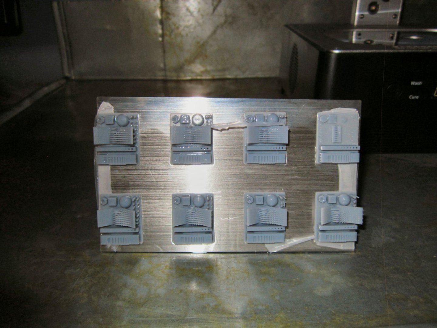
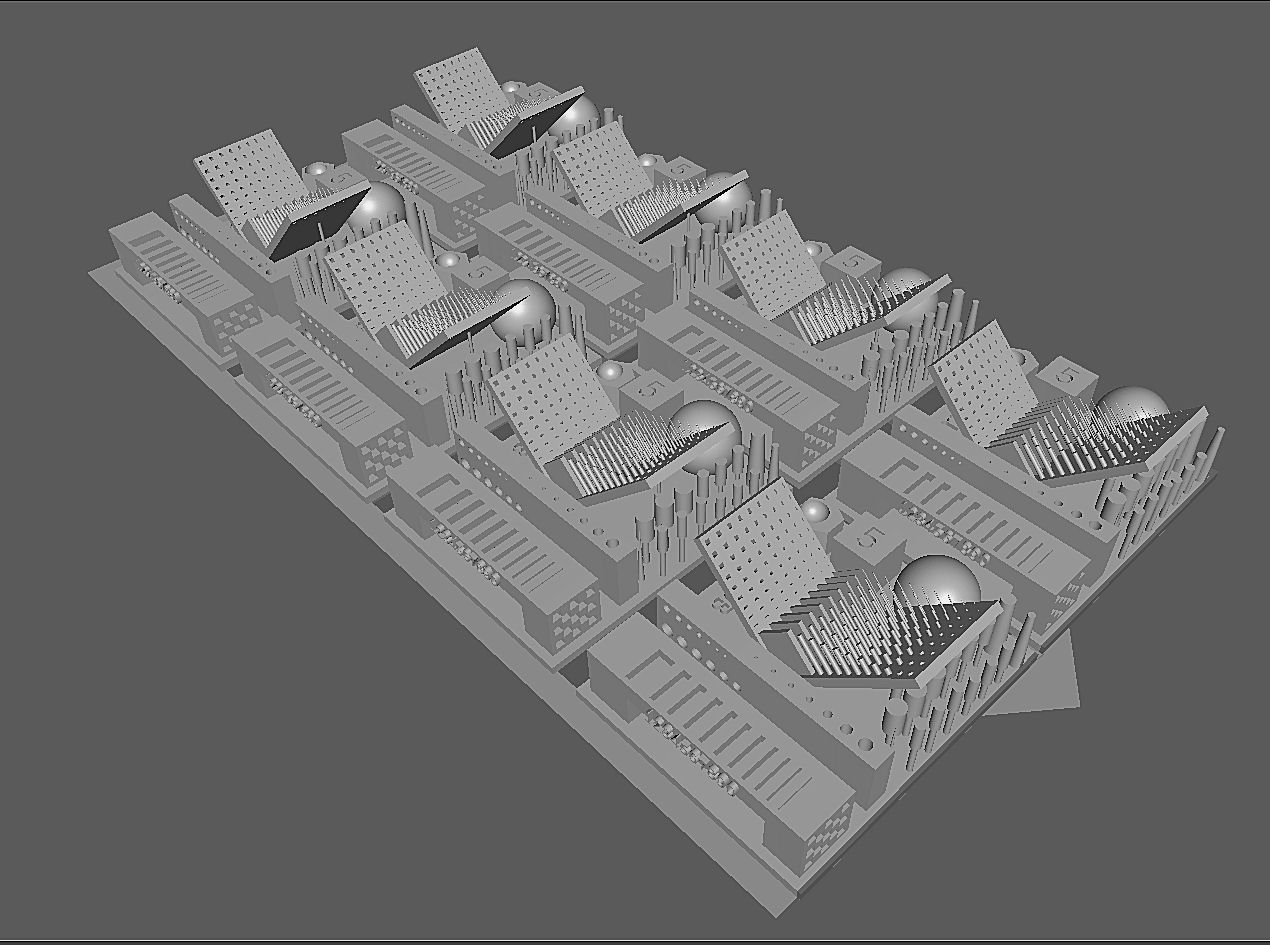
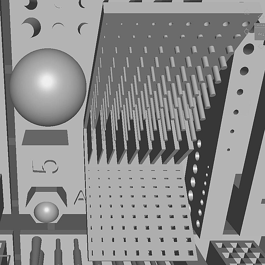
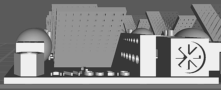
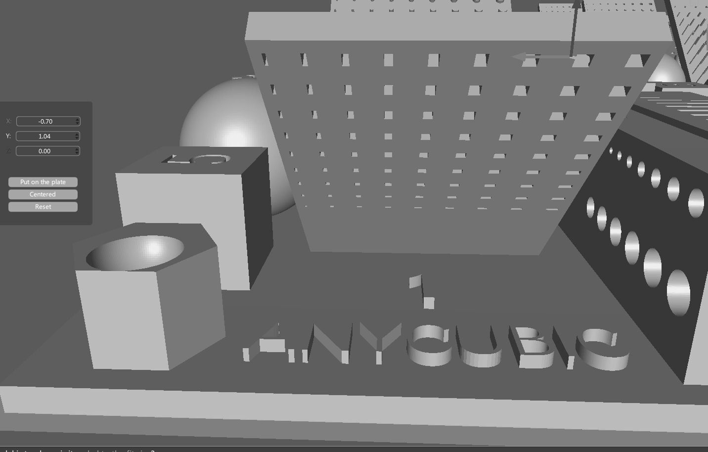
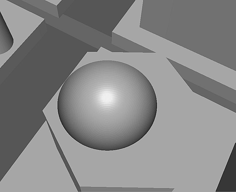
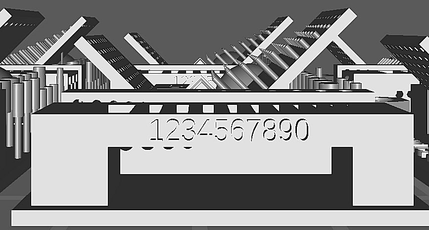
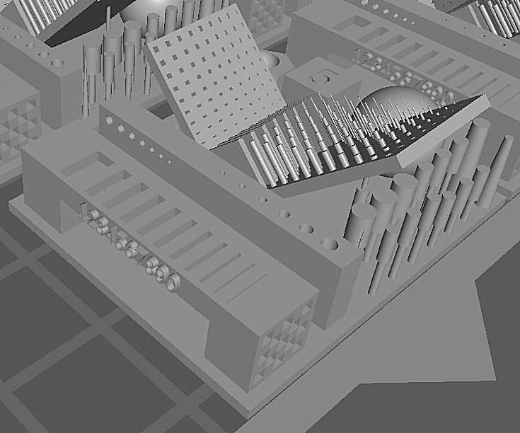
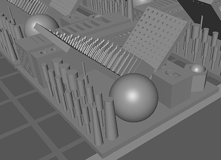
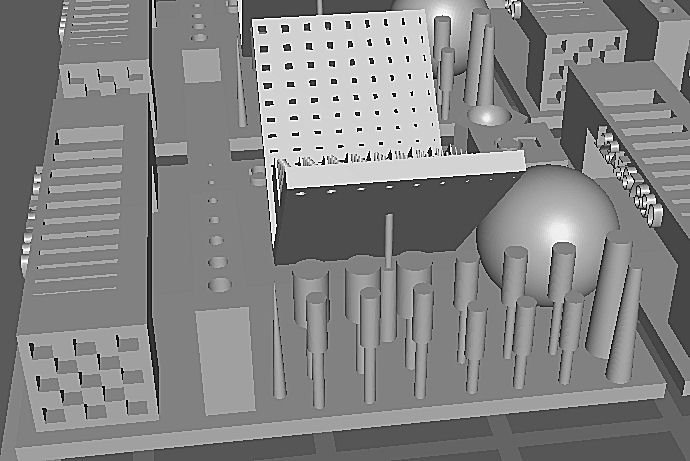
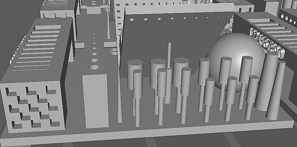
Anycubic R_E_R_F File – Detailed Look at what is being sent to the printer This is a detailed look at what the Anycubic R_E_R_F file is sending to your printer, so you can determine the correct exposure for the resin you are using. As a general note, I am not an expert in resin printing. In fact, I’m just starting. That is one reason I made this write up. The advice I give on setting the exposure from the results of this test, is what I have gleaned from videos and write ups I’ve found on the internet. This advice is from several well respected YouTubers and various resin printing forums. Your mileage may vary, and please, just use this as a starting point for your adventures. This is my best analysis of the print and what the tests are. The file prints the same part at different exposures, with print #1 being the least exposed, (1 second) and each subsequent print exposed, at an additional 0.25 seconds. Print #8 has the longest exposure time. These times are for the Mono 4K. I don’t know if the interval is the same for the R_E_R_F files for their other models. According to Anycubic, you can change the initial 1 second time, and the rest will follow at 0.25 second intervals from the new time. My computer will not run their latest slicer software, and the next lower version will not open this latest file, so I could not test this. OK, you have printed out the Anycubic R_E_R_F Exposure. Great! What the heck is the original print supposed to look like so you can judge the results?? As a note, it is best to observe the prints before washing, after washing, and after curing. Each process, especially curing can lead to warping of the part, and some of the details. After the first wash, it might be a good idea to go back and hit the areas with through or blind holes with a toothbrush, to make sure any uncured resin still in them is removed as thoroughly as possible. Handle all the parts carefully, as there are many fine details on them, that can be easily broken off. I noticed that after a day or so, the block, mentioned later. with the seven blind vertical holes in it seemed wet in that area. I think that the smallest holes did print, but still had uncured resin in them after washing, and curing. I will have to come up with some way to clean out such small holes, if any of my regular prints contain such. All the parts are likely to warp during curing, hence the checking, where possible before curing. How to prevent this is left up to more experienced types than me. I think I cured them for far too long. I used a 10 minute cure, I think 2 to 5 is the recommended time. This print has many different tests included so there will be a lot of areas to be checked. In the end not all areas will probably be the best on one part. You will have to pick the one that is the best overall. Start a small print at this setting, then several others varying the exposure by 0.1 or 0.2 seconds on either side of this setting to dial in the best exposure (for an Anycubic Mono 4K). For other machines you may have to use a larger or smaller interval. Here is a picture of my first “successful” print of this test. The failure of the upper right is due to part of my failed actual first print that was stuck to the FEP, I should have checked the FEP before I continued. I think that the sheets of flash, also were caused by this. On all the tests with a series of objects with decreasing size, it is likely that some of the smaller objects or holes may not print. The best you can do is select the exposure that produces the most ones. This is where hitting the holes with a toothbrush and cleaner, may clear out a hole that printed, but still has uncured resin stuck in it. For small details on your regular prints, you may want to do this too. I managed, after playing with several programs, to convert a copy of the R_E_R_F.pwmo file to a Sketchup .SKP format, then imported it into CHITUBOX. These are screen shots taken as I zoomed in to get a closer look at what is being sent to the printer. I have not been able to break up the 8 print group so that I could look at just one part, so the pictures will also show adjacent parts. This is the best I could do. This is the entire 8 part group. The thin border shown in this, and other shots, is the CHITUBOX working surface. This picture shows one of the center angled plate areas seen from the top. This area has flat vertical plates printed at the corner joining the two angled plates. Each plate is thicker than the one next to it. The pillars also change diameter as they go from one side to the other, I think matching diameter to the plate thickness in that row. In addition as the pillars progress from the center corner out they get progressively shorter, until ending at the second to last row. The last row consists of through holes the same diameter as the adjacent pillar. This picture shows both surfaces of the angled plates. The second angled plate consists of square through holes, that appear to be the same width as the vertical plates and get longer as they progress to the outside. Check that both angled plates are flat in both directions. This shows the other side of this plate. The long vertical block on the right has a series of varying diameter horizontal through holes printed in it. This block also has a series of vertical blind holes printed in its top. I’ll show these later. The end of the next block has a depressed circle with two crosses printed in it, One cross is raised (the X) the other depressed (the +) relative to the bottom surface of the circle. This shows the same area from a higher angle. Note that the print number is displayed here. Check the lettering here to see if any letters are missing, incomplete, or blurred. In the two pictures above is shown an additional two tests. On the left is a hexagonal tower with a hemispherical depression offset to touch one face. Note that in the file the wall on that side has a flat top, at the joint, many, if not all, of the final prints will have a notch or gap here. The smaller the gap the better. I was using a Wash and Cure station to clean the parts. The washing action may have washed away this thin area. If your print has such a feature, perhaps careful hand washing would preserve it. The next two pictures are of the last block at the end of the part, the one that has the crosses on one end. On the outside edge of this block are the numbers 1 through 9 and a 0. Check that these are all present, and crisp, not blurry. Also check that the bridge section is straight and the opening is square. The next picture shows the top and the end opposite the crosses of this same block. Verify that the checker board pattern on the end is complete and crisp. The top has a series of long depressed boxes. Check these, and compare the actual number printed to those that were supposed to print out. This is another area that hand cleaning may have helped. In some prints, it looked like the smallest boxes may have printed, but not been completely cleaned out before curing. The above picture also shows the seven blind vertical holes in the top of the adjacent block, that I mentioned earlier. At the other end of the print, next to the previously mentioned hex pillar are two additional shapes. One is a cube with the number 5 inscribed in the top, and the other is a sphere. Checking them is self-explanatory. In the above picture you can also see the rod and pillar and tapered columns that are under the one angled plate. I did not see these and broke most of them off, while handling the cured prints, before I noticed them. These should all be present, and straight. The next pictures are more close ups of these. In the picture below, note the pillar under the angled plate closest to the corner of the two plates. It should be attached via the thin cylinder to the underside of the plate. Also note the previously mentioned through holes along the top of the plate. If anyone sees something I missed, or mistakes I made, please speak up! I hope this helps you to improve your prints! Here is a link to another short write up on this subject, I found: https://www.reddit.com/r/AnycubicPhoton/comments/fnym88/improving_adhesion_understanding_photon_s_rerf/

-
Yes, the therapy consists of a large group discussion, where we all talk about our problem, and assure each other that were perfectly sane! I understand that many Admirals disagree with that conclusion, at their own meetings, but we're right! The next speaker at our local meeting, is Napoleon! It will be exciting!
-
After asking about the exposure test on the Anycubic Facebook page, the parts have a number printed under one of the overhanging pieces. Now I need to print a new set, and take more care removing them from the build plate.
