


thibaultron
-
Posts
2,951 -
Joined
-
Last visited
Content Type
Profiles
Forums
Gallery
Events
Everything posted by thibaultron
-
How do you refill the vat in the middle of a print, so as to not affect the print?
-
 A great YouTube site for learning machining is: https://www.youtube.com/c/mrpete222 He is a retired machinist and shop teacher. Warning: A Huge Major Rabbit Hole! For those of us with the 7X12,16 etc. Mini-lathes, there are a huge number of videos on YouTube on adjusting and rebuilding them.
 -
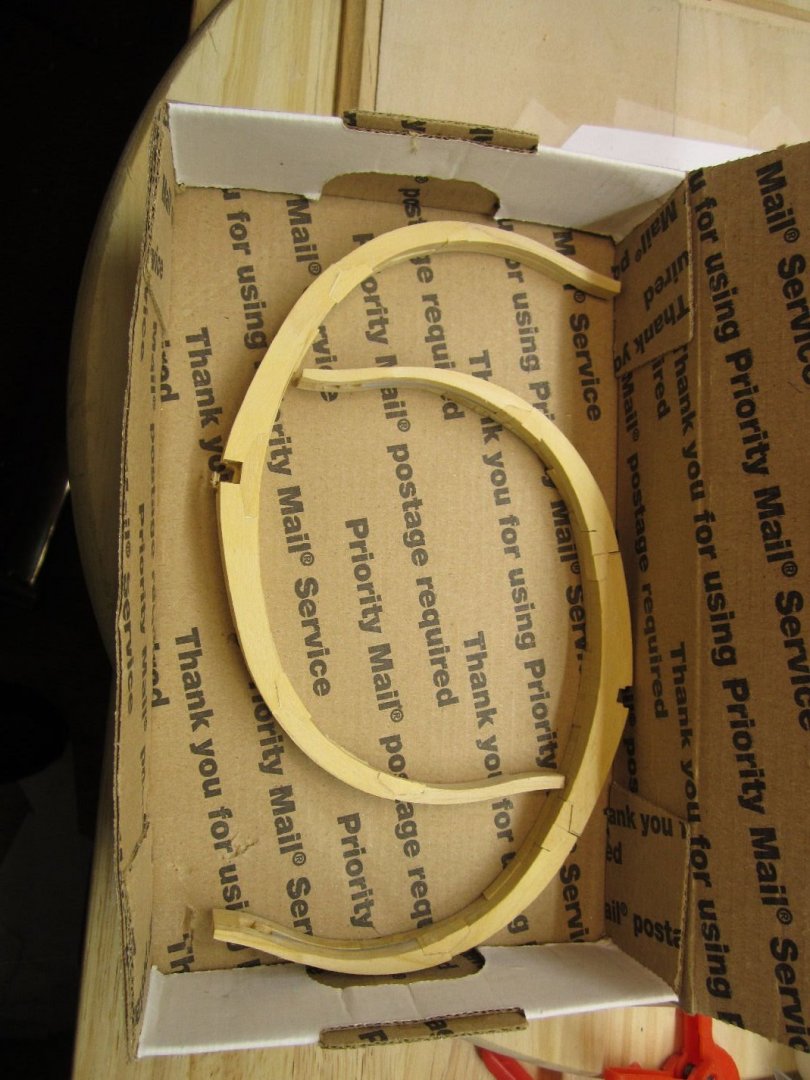
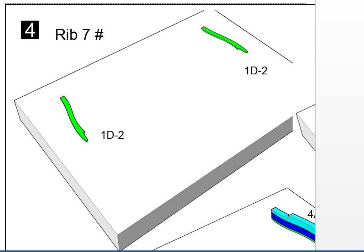
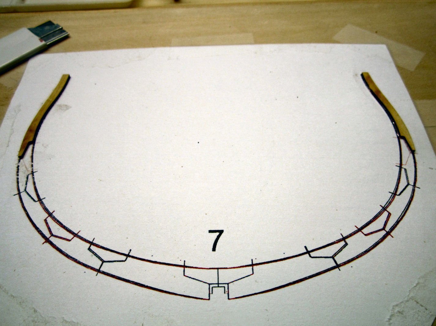
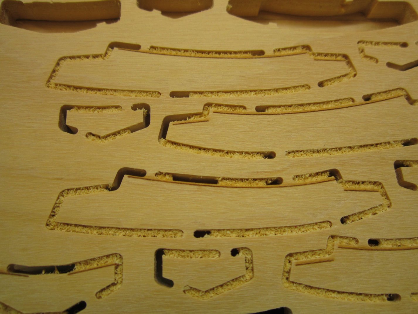
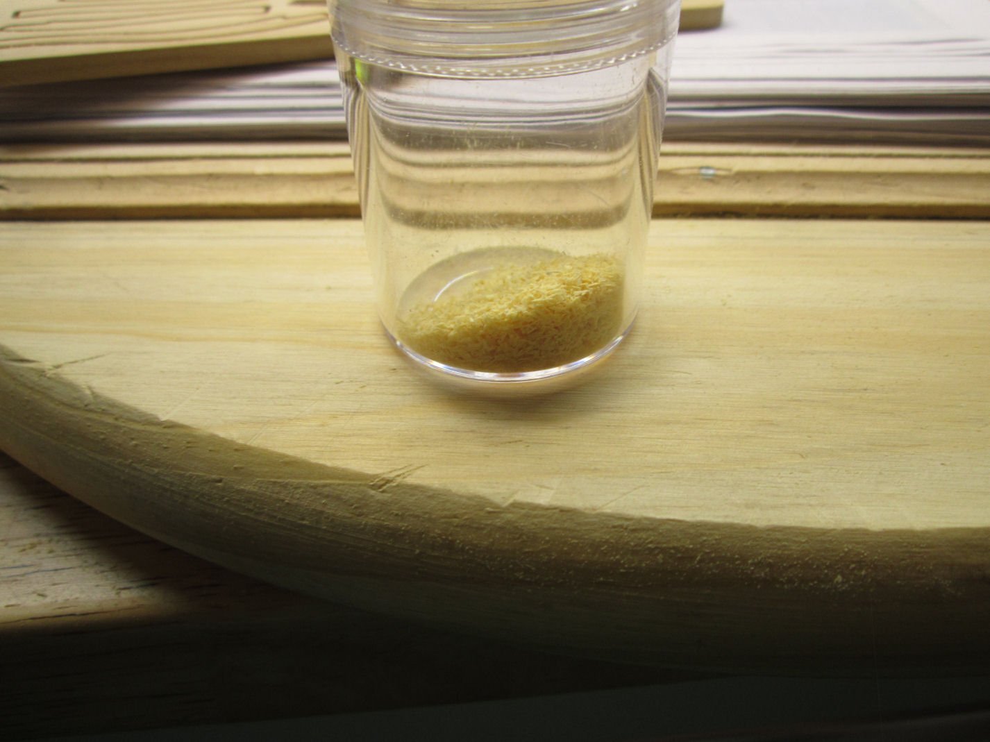
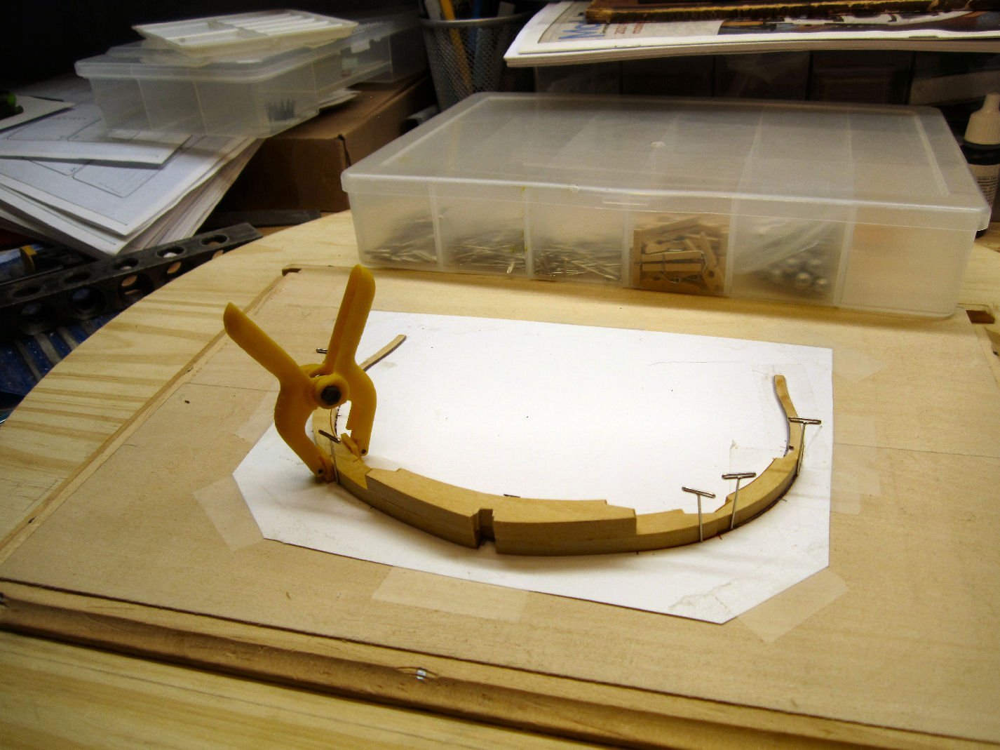
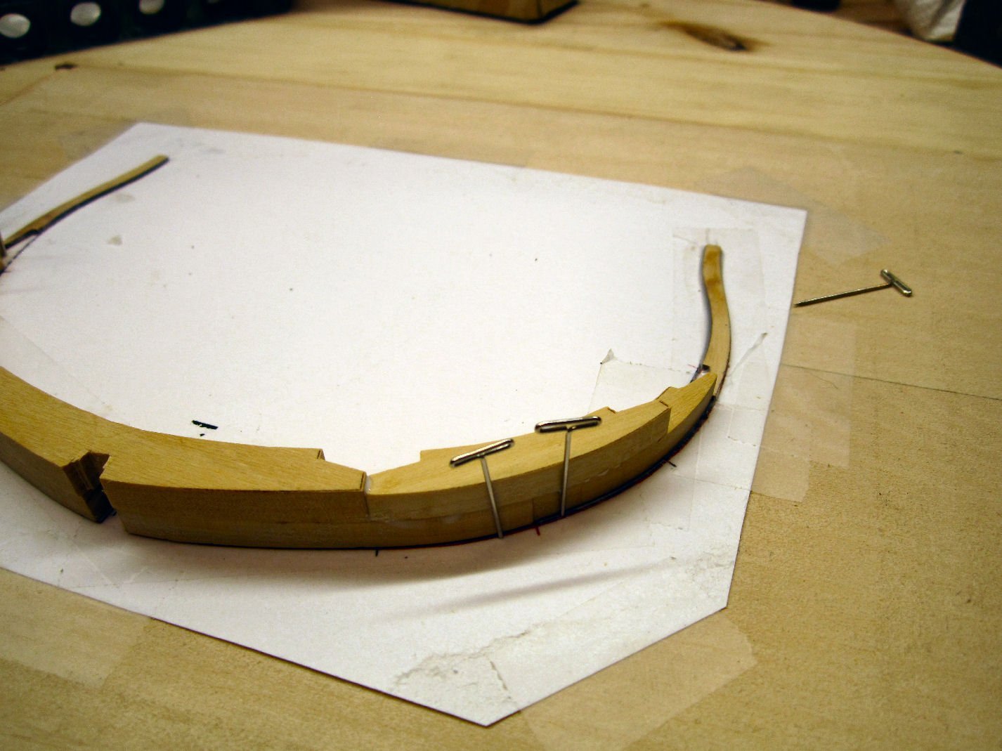
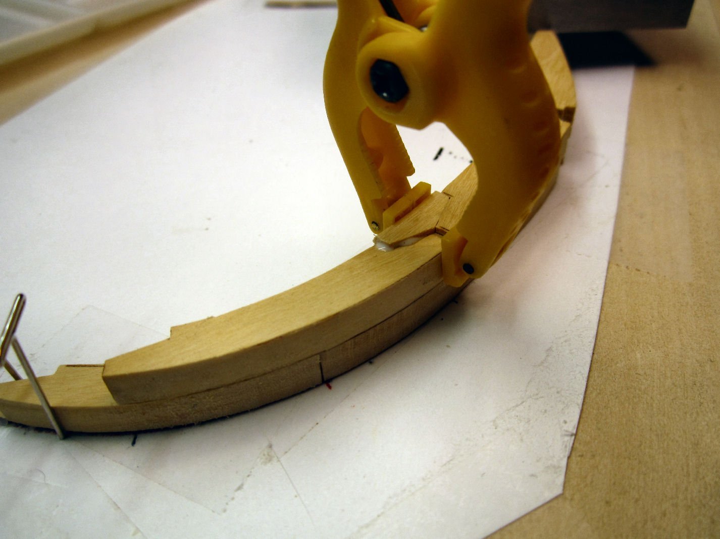
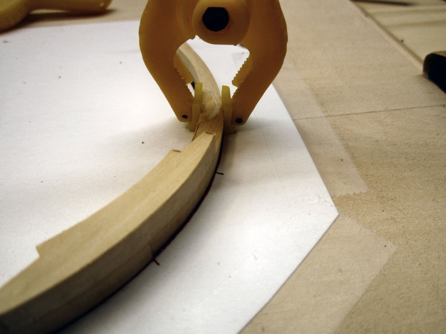
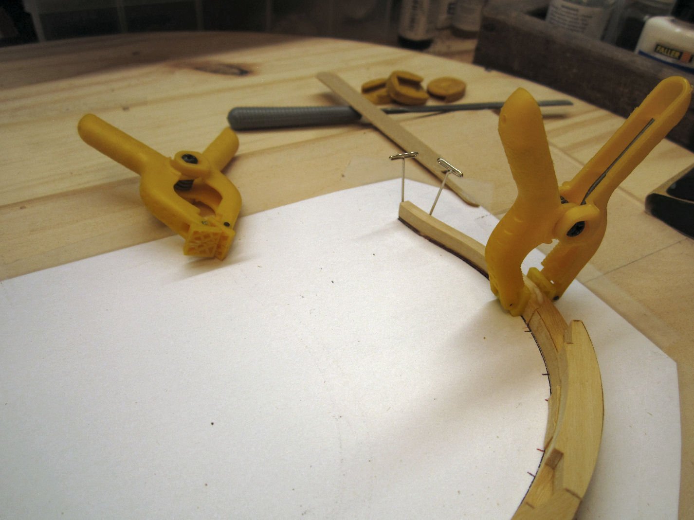
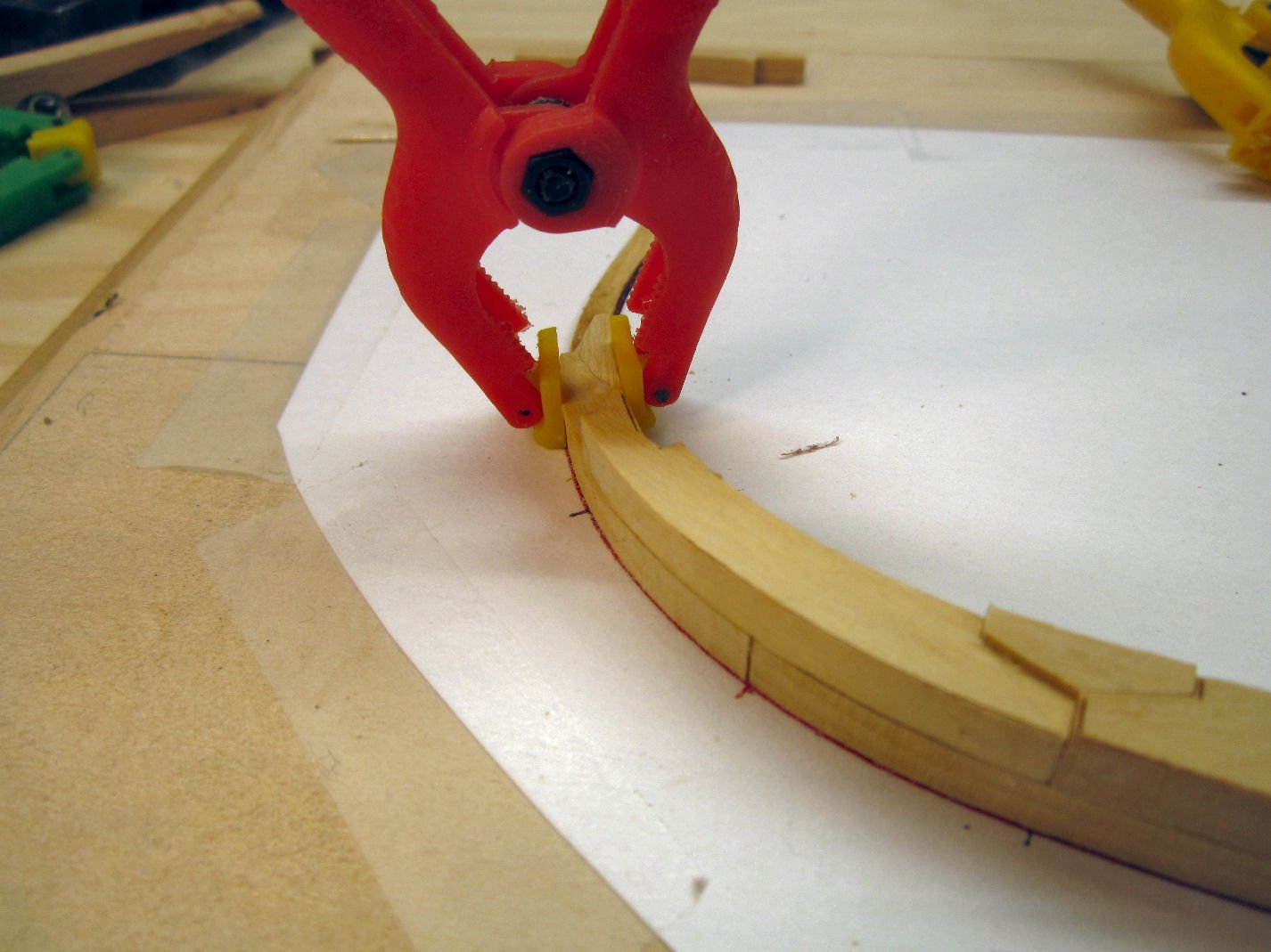
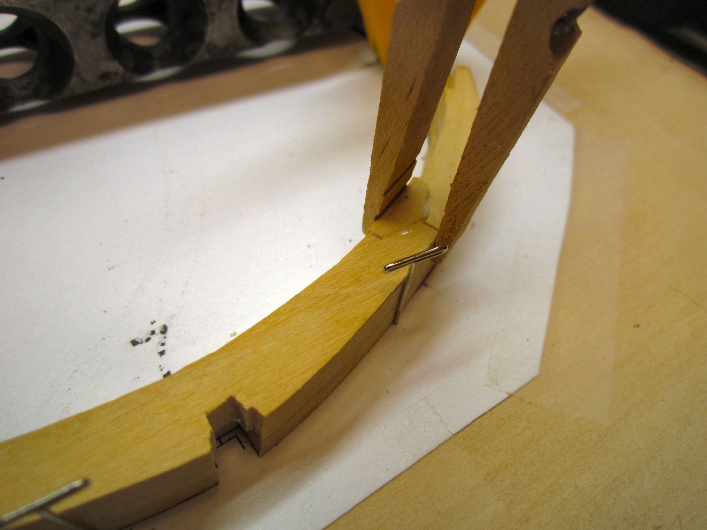
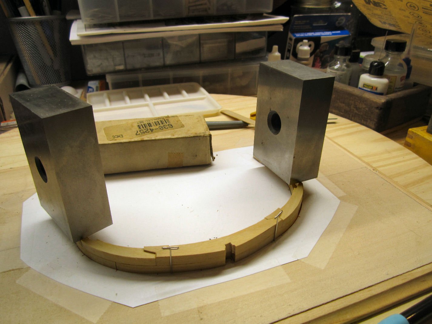
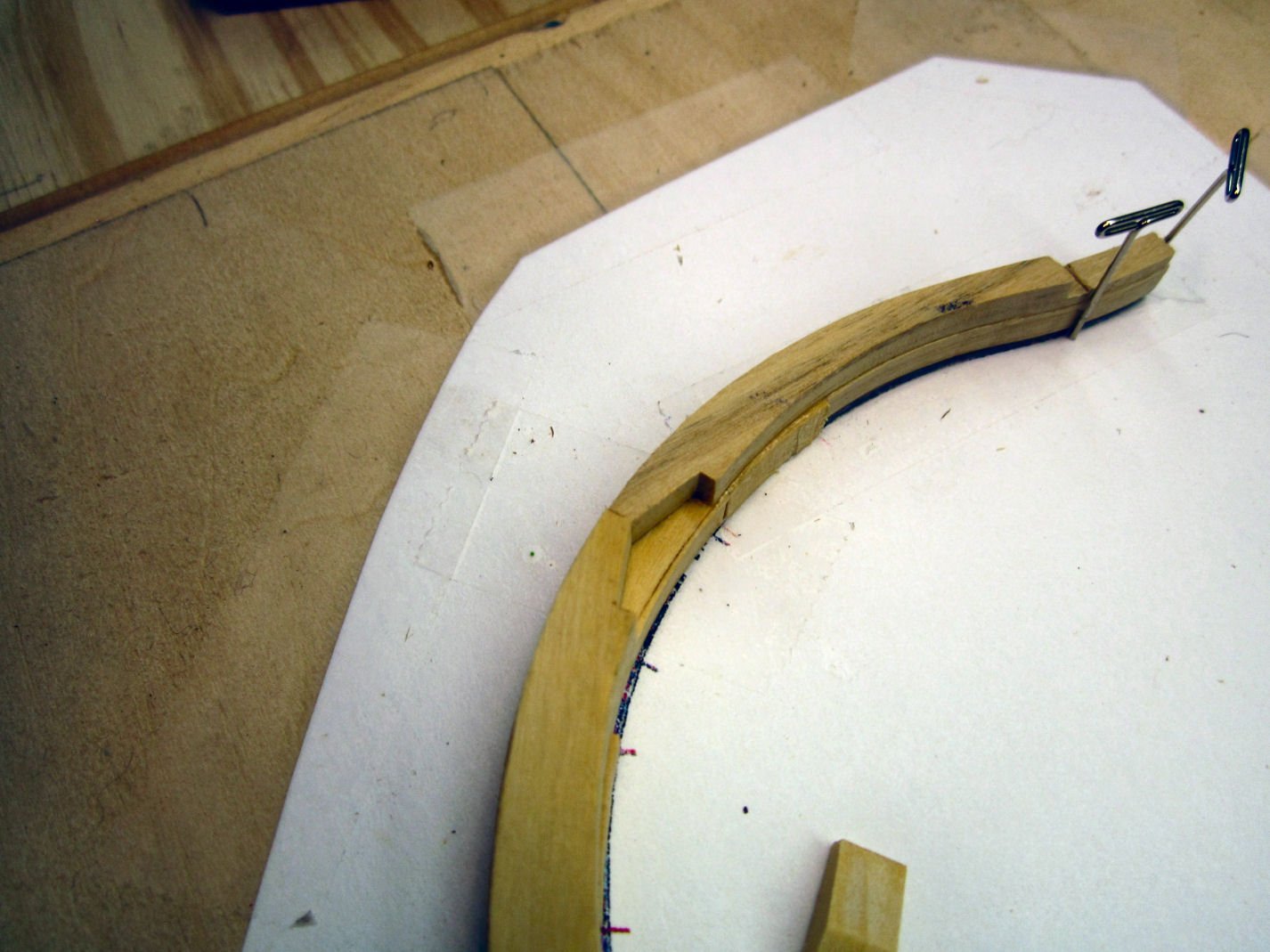
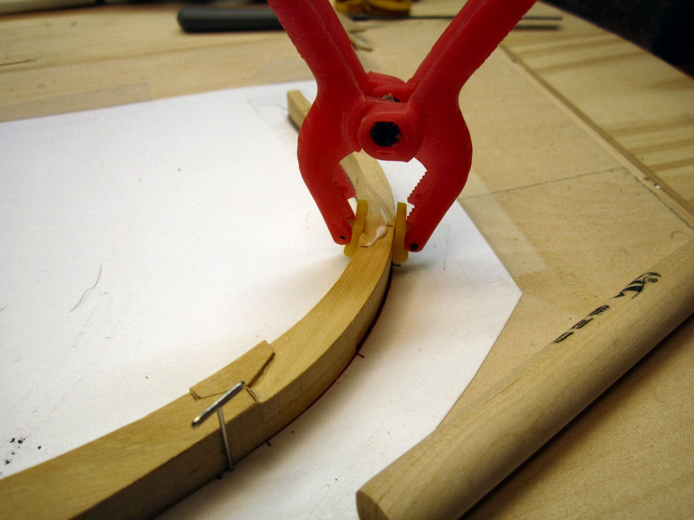
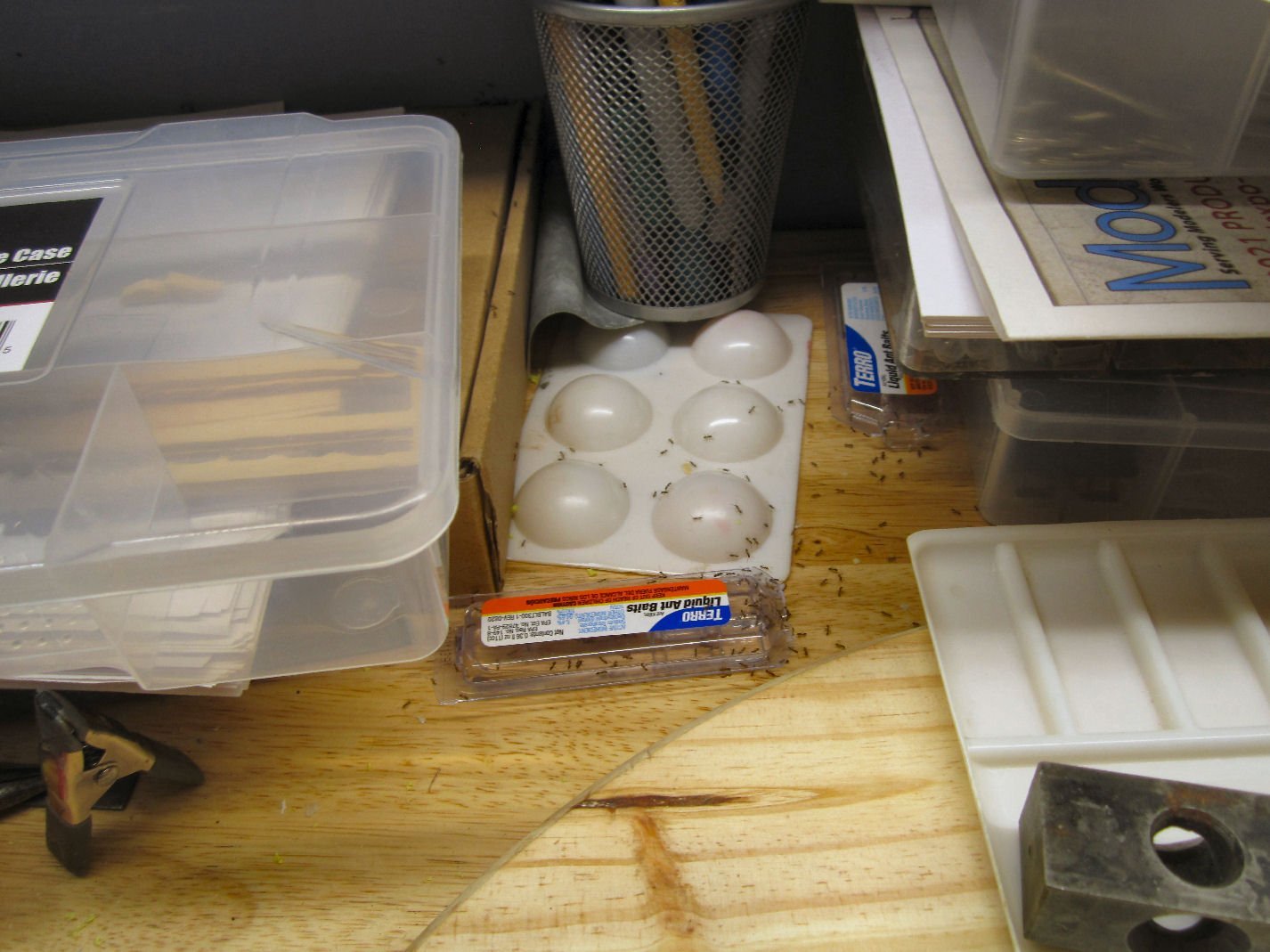
Part 011 First here is a picture of two of the frames nested in the small box, as I mentioned in the last post. Yes, that second frame is Frame 7, finished. This one should be able to hold another layer of frames. Back to the construction of Frame 7. Once again I started by taping down the frame drawing I printed on cardstock after scanning the drawing in from the plans (a good choice as described below). Then I glued down the upper frame shims, and applied clear tape over the drawing areas, to keep the frame parts from sticking. Note: that the drawing for Frame 7 shows that the upper half of the frame (Black) is shown offset slightly higher than the lower (Red), I missed this, but there is enough meat on the frames that sanding can correct this. When cutting out the frame pieces, I hit upon an idea. One of the standard ways of filling gaps, is to mix sawdust with the glue you are using, and there is a lot of sawdust left between the parts and the carrier sheets. I had been throwing this away, but now I free the parts over a piece of paper and sweep them into a small container, for later use. I decided to build this frame differently than the first. Instead of building the first layer, complete with chocks, I built it by gluing the mating ends of the frame pieces together before hand. I did glue in the keel chock with the lower frame, as this set the gap to fit over the keel. The reason I did this was there were gaps between the mating ends of the frame sections on Frame 6, where I didn’t trim the length of the chocks correctly. Everything looked good when it was on the drawing, but they were noticeable once I removed it. I also, with this frame, started building the upper frame half on top of the lower as I worked up the frame. This insured they were both following in line, unlike the problems I had with the lower frame not lining up with the upper, on Frame 6. As I would span a chock space with an upper frame section, I would go back and remove the frame and fit the chock in, after the glue on the frame section had dried. This gave me tighter joints between the frame section ends. I generally let the glue set overnight, and it was at this stage when I decided that, while the glue dried, I’d build a simple plastic model between gluing. This worked well, until I knocked over the plastic glue bottle onto the frame at the above completion level!! I can report that Elmer’s will stand up to being soaked with plastic glue, at least the brand I use! The cardstock frame drawing, not so much! I had to remove the drawing scrape the paper off the shims, and glue them down to a new copy of the drawing. At this point I forgot to put the clear tape down, and had to carefully separate and clean the frame, the next time some glue got between it and the frame. Sigh. After this fiasco I continued building the frame. Here and on the other side, I did glue in the chock to make sure it fit in the notch of the shim piece. The blocks used for weights below, are cheap (at least 20 or so years ago) 123 machining blocks. The 123 blocks are 1”X 2”X 3” blocks that are a standard part of machining setup pieces. Normal 123 blocks are drilled and sometimes tapped in several places, hardened steel blocks used to insure your work piece is set squarely in place for machining. These are a cheap set with only the one hole. The tip sections of the upper and lower haves sit against each other, with no resin spacer, like those used for frame 6 During the construction, I had a labor dispute with some ants as to who the workbench belonged to, and had to settle the disagreement with Extreme Prejudice! The finishing of this frame and the start of Frame 8 will continue in the next part.
-
There will soon be more updates. My time lately has been taken up with preperations for and the actual surgery my wife needed. I am also having problems sitting at my computer due to pain from my bad hip. I've completed two more frames, and have the photos, but have not been able to do the writeups, yet. Hang on and more parts will be posted soon.
-
HO trains and layouts by popeye the sailor
thibaultron replied to popeye the sailor's topic in Non-ship/categorised builds
The host of this plays a bit of the fool, in his videos, but here is the starting of a SD-40 locomotive, as well as three different Trackmobiles. -
The free version of Fusion, has another program NetFab, that I use to check/correct my SketchUp projects before I send them to Shapeways, that does a good job of fixing those missed connecting edges.
-
Thanks, I wondering about how to treat the IPA.
-
Which CNC Machine to get?
thibaultron replied to KrisWood's topic in Modeling tools and Workshop Equipment
The 600X600 would do it. So for Sainsmart you would have to get the 4030 with the 6060 extension kit. -
Which CNC Machine to get?
thibaultron replied to KrisWood's topic in Modeling tools and Workshop Equipment
Of the generally considered afford about ones for hobby use Sainsmart seems to have one of the best reputations. They have the 3018 Prover (made with aluminum frame)(don't get the cheaper of their models, or the off brands which are made with bakelite parts in the frame) with a 300X180mm table (slightly smaller cutting area, of course, about 6"x10"). They also have the 4030, 400X300mm. Both have extension kits available to increase the cutting area. The 3018 can be enlarged to 300X400 with about 10"x12" cutting area, and the 4030 to 600x600. There are many really cheep versions of these out there, but they are also cheaply constructed, with no customer support.I found this company after watching videos by one YouTuber who had initially purchased one of those cheap units, and had many problems with broken/nonfunctional parts, and no replies by that manufacturer. There are also other quality makers of the 4030 size cnc carvers, but price goes up acourdingly. Get on YouTube and search for the SainSmart machines, lots of good tutorials. -
HO trains and layouts by popeye the sailor
thibaultron replied to popeye the sailor's topic in Non-ship/categorised builds
Look up Walthers, the biggest Model Railroad supplier. -
Welcome!
-
Welcome! The Model Shipways three pack would be a good start. The older Midwest kits are also good starter projects. Bluejacket also has some beginner level kits. Model Shipways will replace parts you damage.
-
Yes, but the resins are very toxic, as in you should only use gloves, safety glasses, and a mask, when handling the uncured resin. After the print is cured, you can then handle it unprotected.
-
I'm looking at the mono also. Be careful if you have pets or children around, the resins are toxic. If you watch the "What's Neat This Week" #158 podcast with Ken Patterson (on YouTube), one of the members, who made a 3D printed HO scale locomotive, talks about the resin he uses to make the print usable in an environment where toughness is involved. Most of the resins are too brittle for general handling. He 3D printed the drive gears too.
-
HO trains and layouts by popeye the sailor
thibaultron replied to popeye the sailor's topic in Non-ship/categorised builds
The outside of kits like that were printed paper that you glued to the block. -
If you want to, you can get free replacement from Model Expo. Your new parts look great though!
-
As a side note, the scar on the characters face, was real. The actor got when he was beaten by the guards in a Concentration Camp!
-
Welcome!
-
Novice is greeting from the Bavarian Alps
thibaultron replied to XS400DOHC's topic in New member Introductions
Welcome!


