thibaultron
-
Posts
2,951 -
Joined
-
Last visited
Content Type
Profiles
Forums
Gallery
Events
Everything posted by thibaultron
-
 How did General Burkhalter ever fit in one of these?
 -
Tell everyone you super detailed it, including Torpedo Worm damage!😉
-
What about putting foam blocks between the formers? It would be easy to then sand in both the deck shear and hull sides. No more starving cows!
-
How about a tutorial on how you make the seas for your diaroma?
-
Airbrush “controls”
thibaultron replied to glbarlow's topic in Painting, finishing and weathering products and techniques
Do a search on YouTube for Barbatos Rex. He has multiple videos on using all type of paints with an airbrush, including artist paints, as well as a video on just the type of airbrush you have. -
Wear plastic/vinyl/etc. gloves while washing, and handling the parts, until they are painted. Oil left by your fingers will affect the adhesion of the paint to the parts.
-
Welcome to the forum!!!
-
Midwest Muscongus Lobster Smack Instructions
thibaultron replied to kloz's topic in Wood ship model kits
The instructions should be available on their site. Go to the listing for the model, and select the instructions tab. -
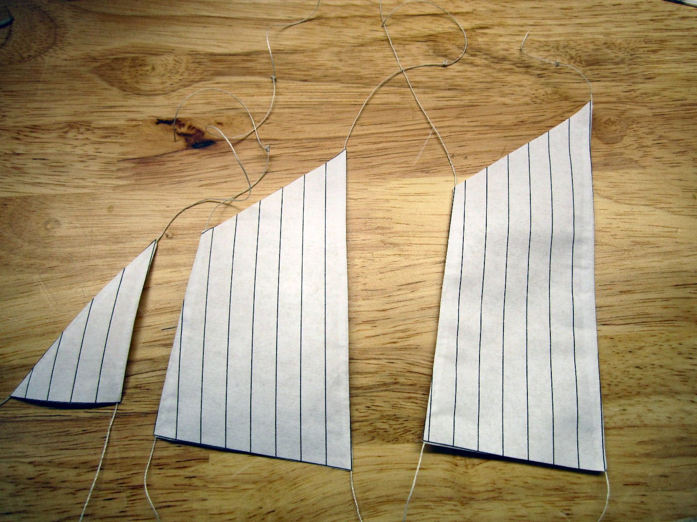
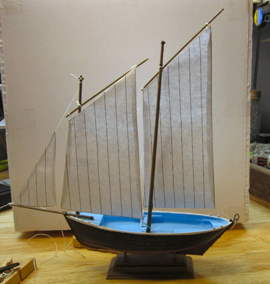
PART 19 This will only be a quick update. I printed out the sails and glued thread to the edges (as it turned out very stiff thread from another old boat kit), and temporarily installed them on the model to see how they looked. They turned out to look right to my eyes, at least. They are not tied all that well, but well enough for the test. Between the stiff paper, the stiff thread, and only having the yards tied in place, it was a major chore to get them on. I didn’t want to tie anything on too tightly either, as it all has to come off again. The fore sail is tilted a bit too far forward, as I didn't have anything convenient to tie a thread to, but looks good when I hold it in position by hand. To be continued.
-
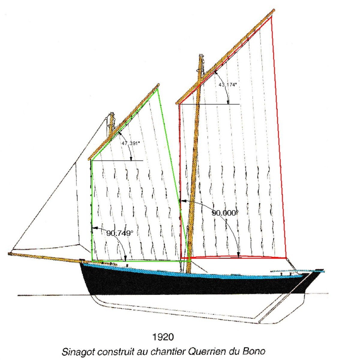
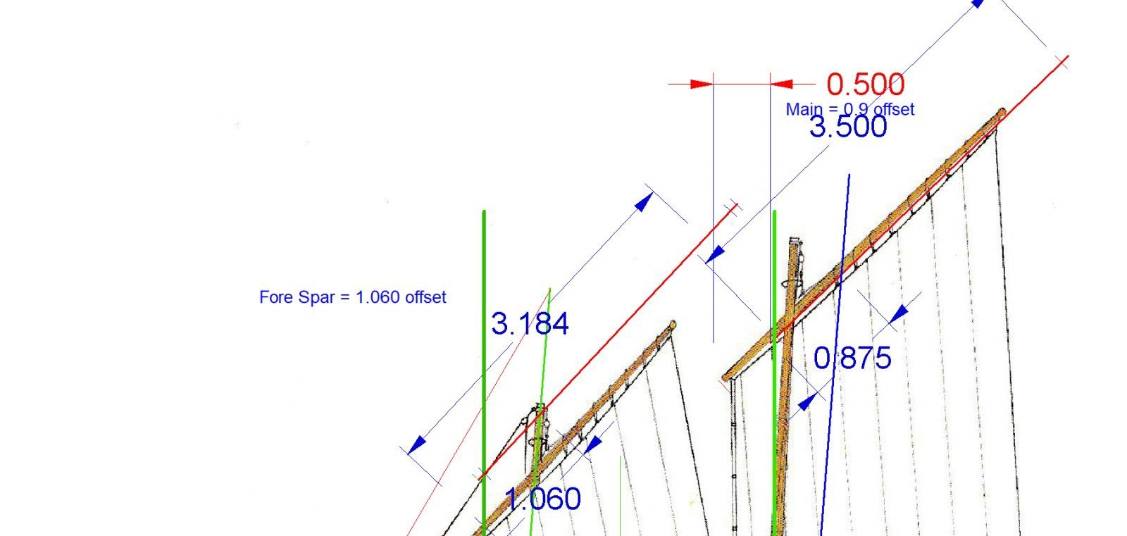
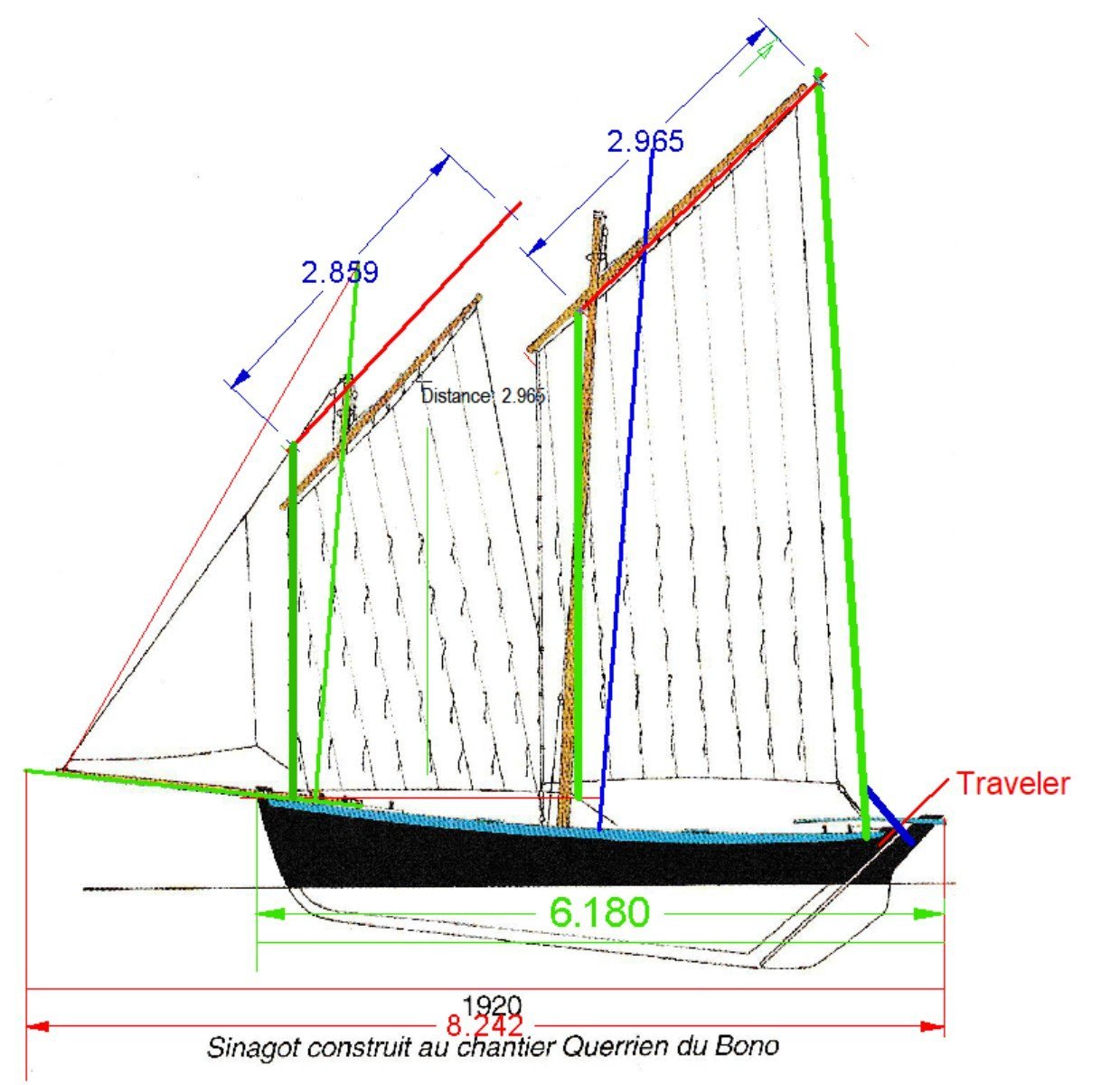
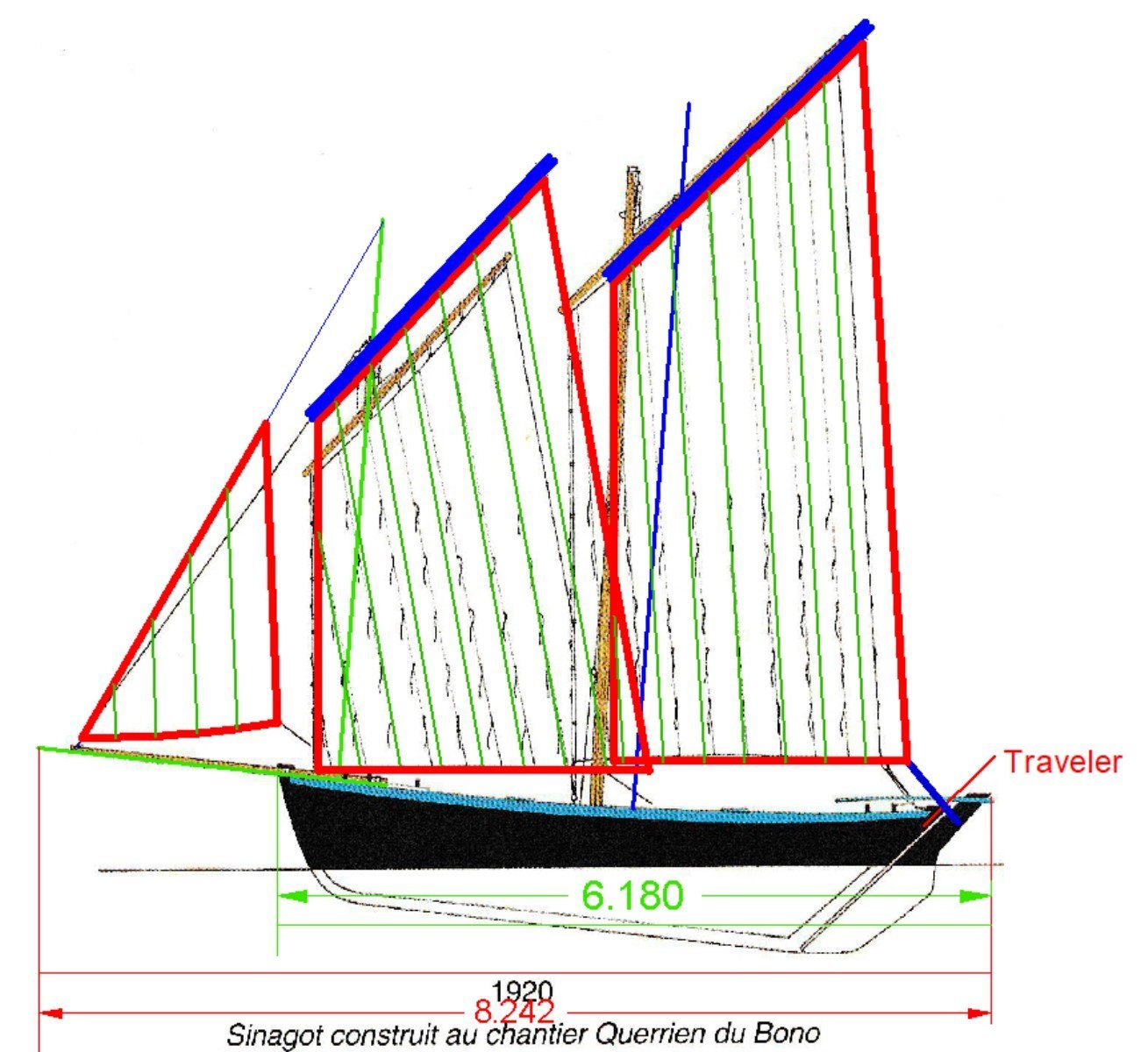
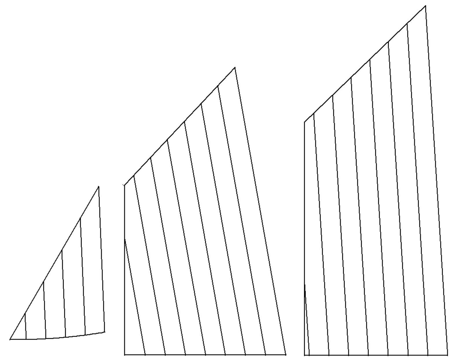
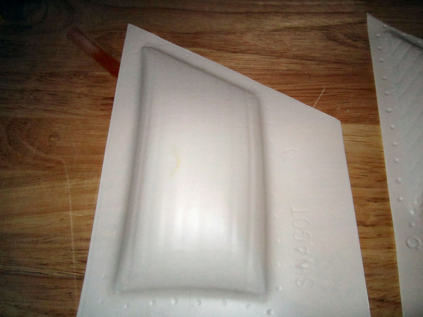
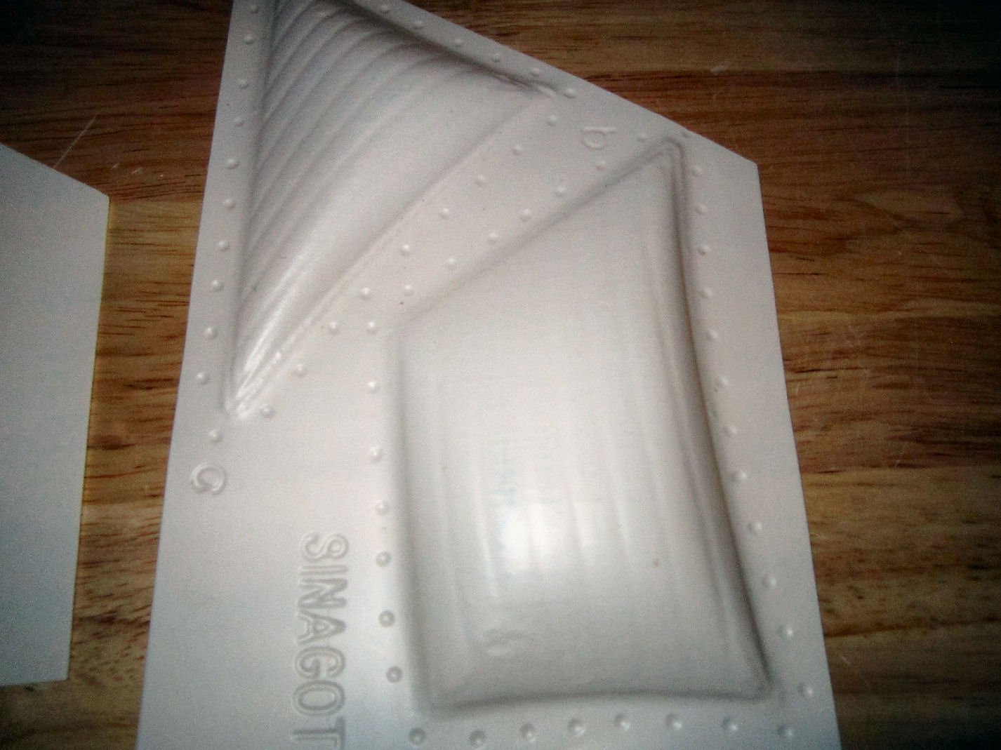
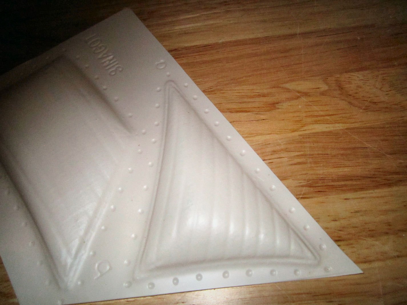
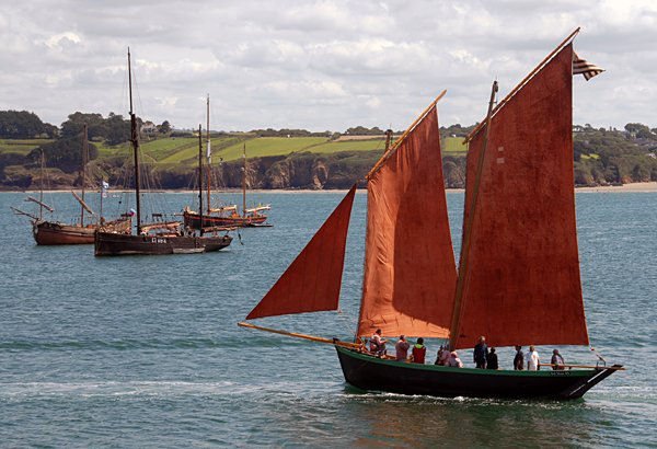
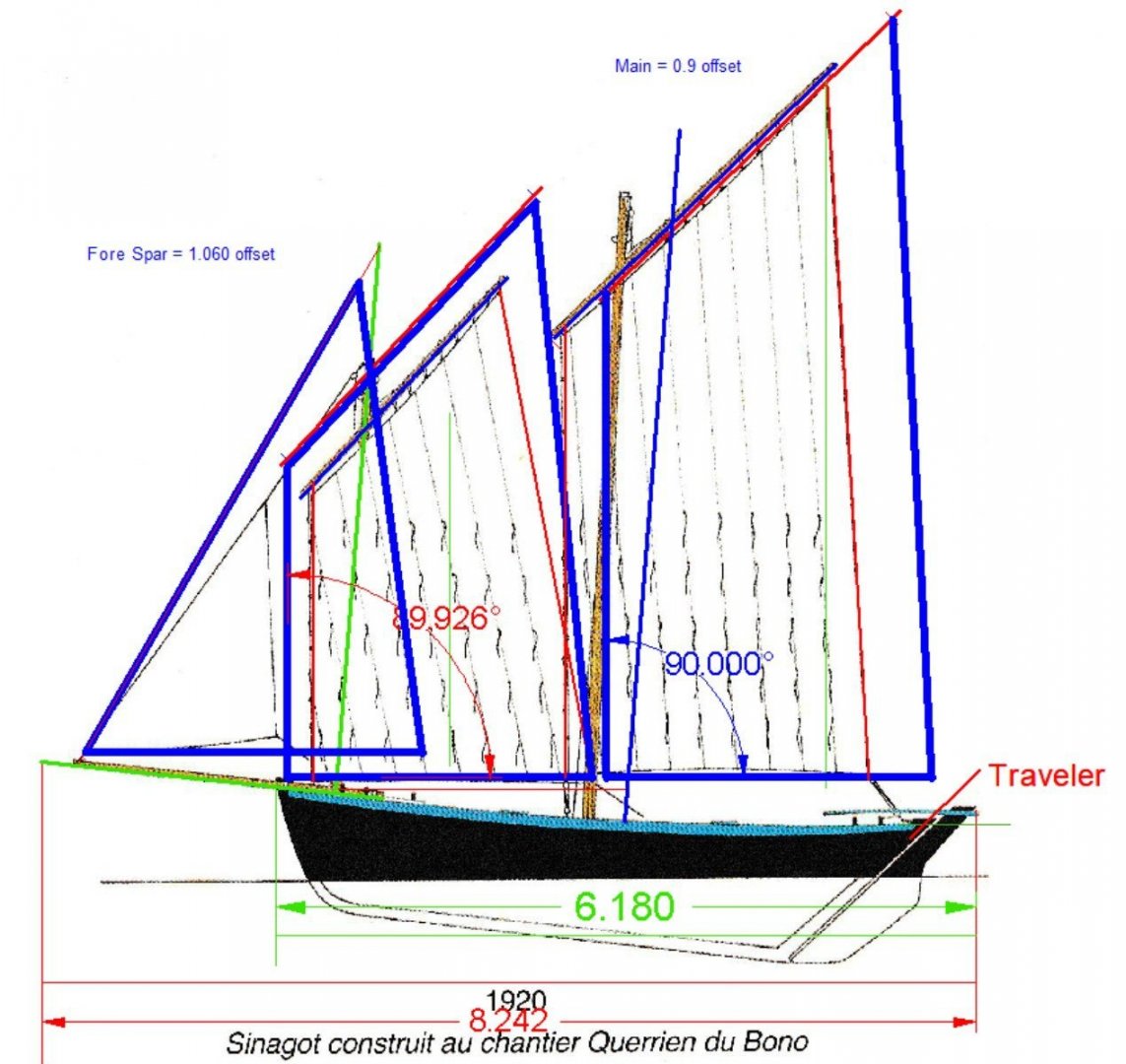
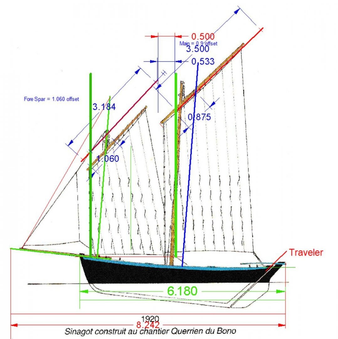
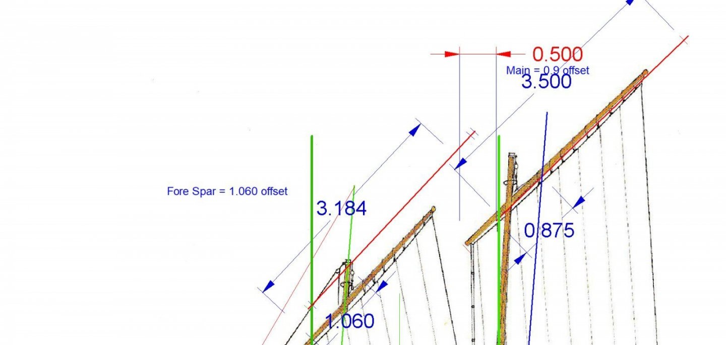
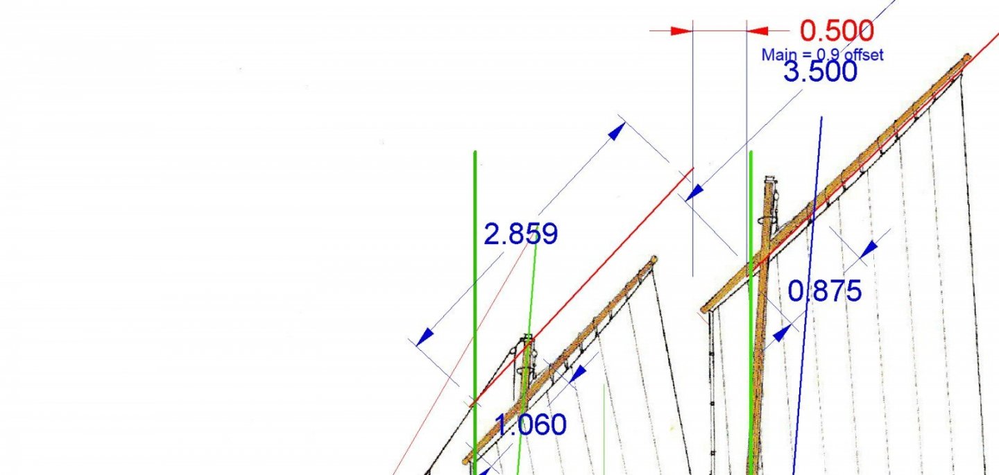
PART 18 Next up are the sails. The kit supplied sails are Vacuum Formed ones, and are quite poor. Many of the sail edges sort of fade into the surrounding plastic with no defined edge to work with. Also the panels are different widths on each one. Not very prototypical! Also they are setup to represent a boat sailing directly downwind. While nice, I want to show the unique setup of this boat where one or the other of the two main sails is preset against a mast when sailing broadside to the wind (explained further below). Pictures of the kit supplied sails. The Main Sail The Fore Sail And finally the Jib. This one, at least, has good edges! The Sinagot book I have has several diagrams of boats from various angles, but only one where the boat has a bow sprit. The picture below is a that diagram with the sails highlighted, and a few measurements shown. The Sinagots did not seem to have bowsprits before about 1920. I guess they were too much trouble when trying to do commercial fishing. After 1920 they started to be used for recreational pursuits also. As the kit has a sprit, I’ll use this diagram as a guide. Some of the things shown here, but not in the kit instructions are: The fore part of the Main and Fore Sails are laced to a line that also pulls the fore tip of the associated spar down to create the slant on that spare. This implies that this line is fairly well and permanently attached once the sails are set. It would cause all sorts of problems to switch the attachment to another spot, unless you either lower the sail, or like getting hit in the head when the upper tip of the spar falls. Hint, sailors really do not like to lower sails in the middle of a voyage, unless weather conditions dictate. The fore section of the main and fore sails is at, close enough for my use, 90 degrees to the foot of the sail. The rake of the masts is about equal, The masts on the model are also raked at the same angle. The slant angle of the spares is close to each other. The jib is on the small side as compared to current practice, on more modern designs. As noted in an earlier post, the main and fore sails are semi-permanently set on opposite sides of the masts. You could set both on the same side, but if set in the traditional manner, you would have to lower the one sail, spin the hoist hook arraignment to the other side of the mast, then raise the sail. Not something you would normally do once you had started to sail, at least for something as simple as tacking. (You never take any longer to tack than as you have to, as you have to complete the maneuver before you run out of momentum and steerage). As you can see in the picture below, they were quite content to put up with one or the other sail rubbing against the mast on a broad reach. In the picture, the fore sail is pressed against the mast. Even on present boats the sails are modestly sized (as compared to the ones in the kit, as will be explained below.) There is no dedicated fore stay. The jib halyard serves this purpose. There are no shrouds. Except for the kit box art, I could find no other evidence of a jib traveler. Though not shown in this diagram, almost all of the other diagrams as well as actual color photographs I have found, show that the sails were almost all red, with occasional patches made from standard modern white sail cloth. The back bottom corner of the Fore Sail falls just at or behind the rear of the main mast. Next I took many measurements from the actual model, and superimposed them on this diagram. The Fore and Main sails, as shown in the diagram, are in red. The kit sails, as close as I can measure them, are shown in blue. The kit sails are shown in blue, as are the kit spars. The kit masts and bowsprit are shown in green and blue. The two fore masts are in the same spot, but the kit main mast is set further back. As you can see the kit sails and main spar, are too large/long for this type of boat. If Ferrari had built a Sinagot, it might have had this much sail area! While the kit main spar is in reality not that much longer than the one in the diagram, with the main mast set further back, it extends well past where it should in relation to the stern. There is almost no room for the main sheet blocks between the corner of sail and the traveler bar, which extends in line with the stern post. So I will be designing the new silkspan sails to a more reasonable size. The first step is to fix the joint between the fore edge/ spar tip downhaul. The diagram indicated that for both sails, this is ~.2” in front of the respective mast where it meets the deck shear. This is shown by the heavy vertical green lines. The tip of the kit main spar intersects, so that is OK. The kit fore spar, though, sits too far forward. The diagram and kit both show about ½” spacing between the main and fore spar tips, so I’ll use that as a standard. Next I repositioned the fore spar. Then shortened it to meet the ½” tip to tip standard. The blue line near the end of the spar marks were the sail attaches. This gives a new spar length (lashing point to lashing point), of 2.859” I moved the position of the main sheet blocks to the position it would be when the sail is pulled to the midline. This would be at the bottom of the traveler. If you tried to set the blocks at the top, they would immediately fall over to one side, and the sail would fall off position. I then measured the length of the block set in the diagram (1/2”) and set this as the back corner of the sail. Then I extended the back edge of the diagram sail until it met this point, keeping the new edge parallel to the old. This set the new main spar aft lashing point. I shortened the spar to match this. This gave a new main spar length, lashing to lashing, of 2.965”. Now, for practical reasons, I’ll make the fore spar 2.875” (2 7/8”) and the main 3”, lashing point to lashing point. After adding a bit of thickness to the spars, I drew in the new sail layout, with scale 21” panel lines. Here is the layout of the sails, per all the above. Here it is with matching thickness lines, and all in one color. Next, I’ll print these, cut them out and trial fit them to the model. If it all looks good, I’ll refine the sail drawings, and add tabs and reef points.


-
For the Bridge windows, perhaps you could glue strips for the mullons to clear plastic, and use the clear part as a structural part of the superstructure.
-
"Well, in my day Sonny, we had to walk uphill at work, Both ways!"
-
As the hull is made from plywood, all the hull sections would be runs of curved (lenghtwise), but flat (cross) sections. You could draw bulkheads using the supplied info, as all the hull sections would be flat between the lines (as is the one section shown. A model could be made from these lines, but if you are looking to make a full sized boat, you will need better plans.
-
Going...going...gone? The London wreck.
thibaultron replied to druxey's topic in Nautical/Naval History
This reminds me of the USS Monitor. She was rediscovered, I believe in the 70s, upside down on the ocean bottom, mostly intact. Then the government experts chimed in. The location was too exposed to shipping , the currents were too strong, the wreck too fragile! two decades later, all that was left was the iron work, and they only recovered the turret, engines, and some of the plate, the wood they were so concerned with preserving had fallen apart, anyway. They could have at least done extensive photo work. -
Could it be rolled up fishing nets?
-
I found the book Hand, Reef and Steer by Tom Cunliffe To be a great resource.
-
NRG VIRTUAL WORKSHOP - AUGUST 21
thibaultron replied to kurtvd19's topic in NAUTICAL RESEARCH GUILD - News & Information
Thank you for a great presentation! -
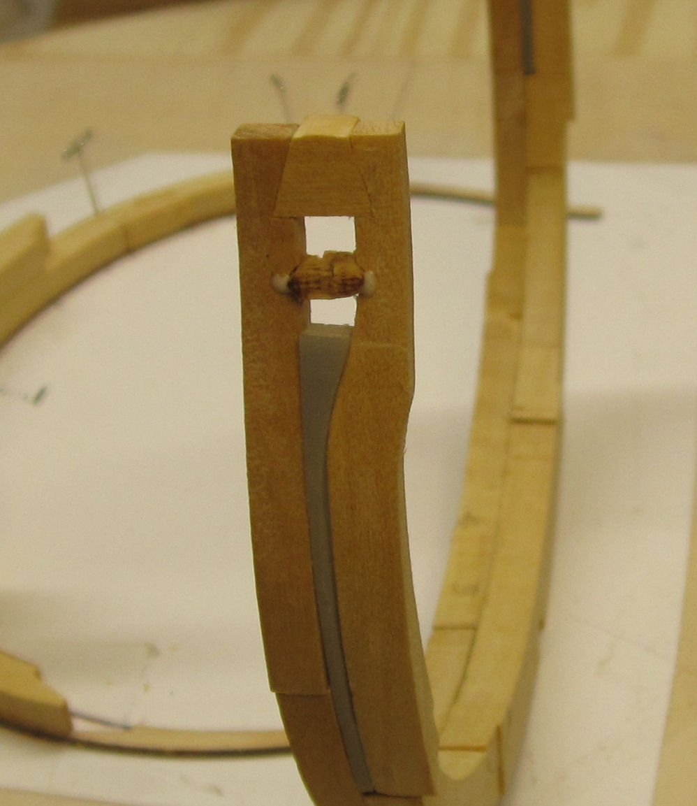
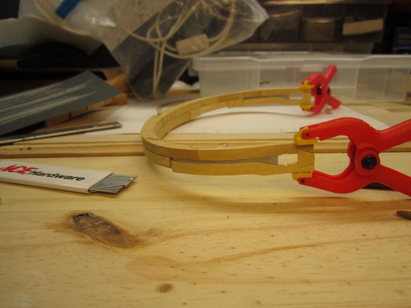
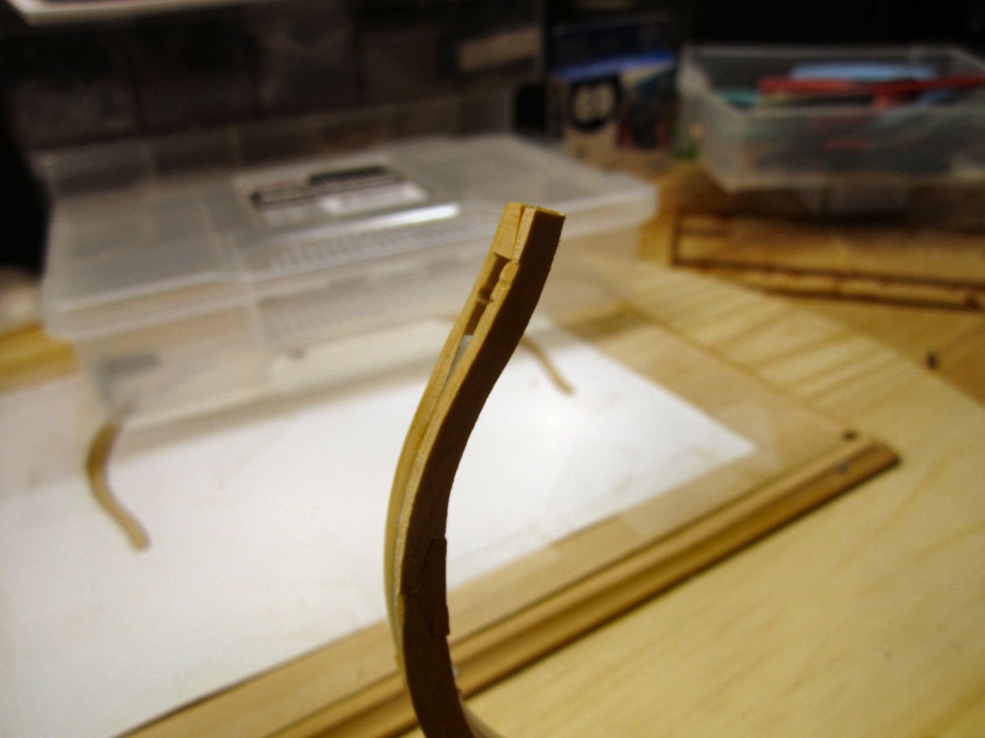
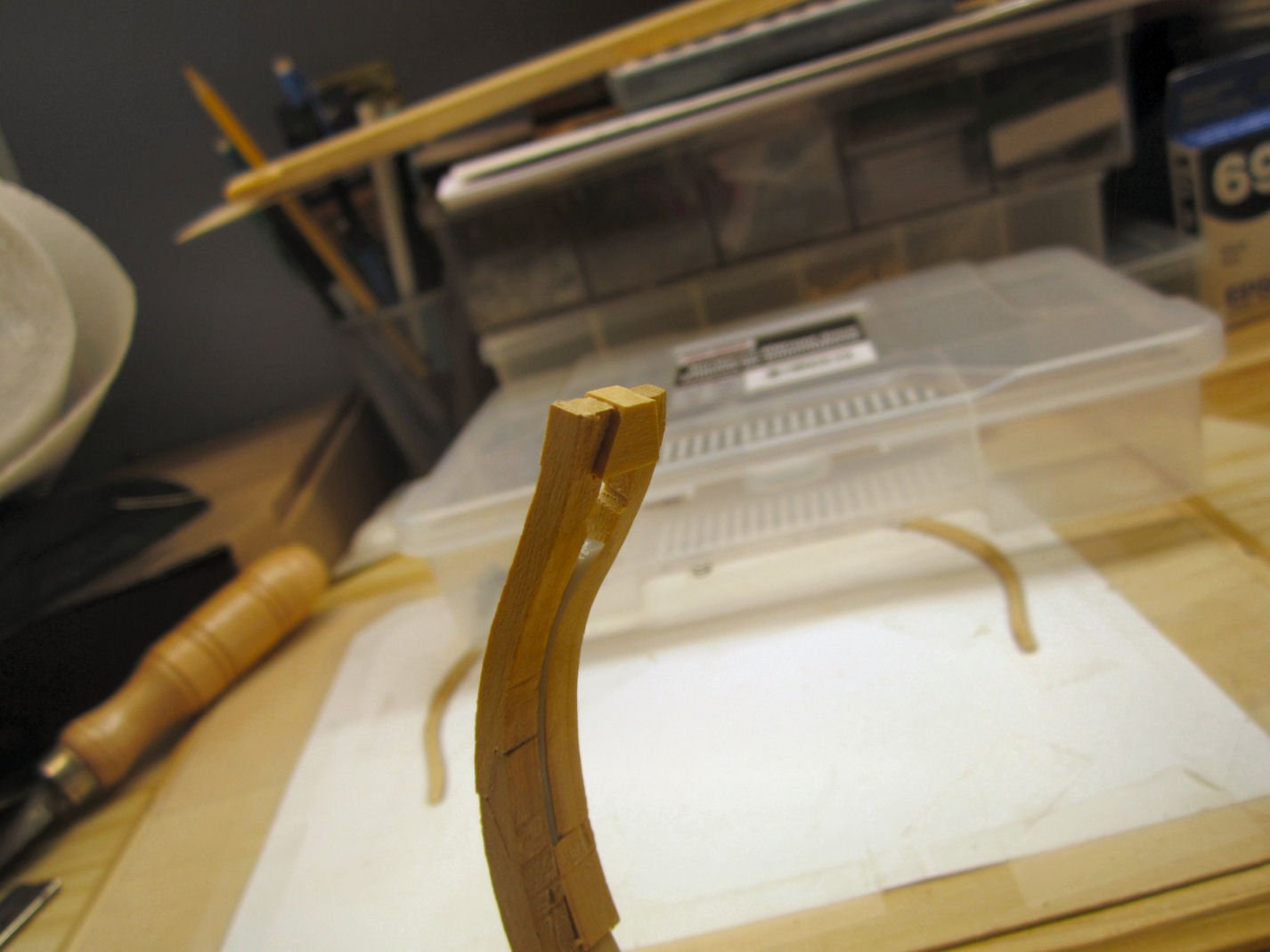
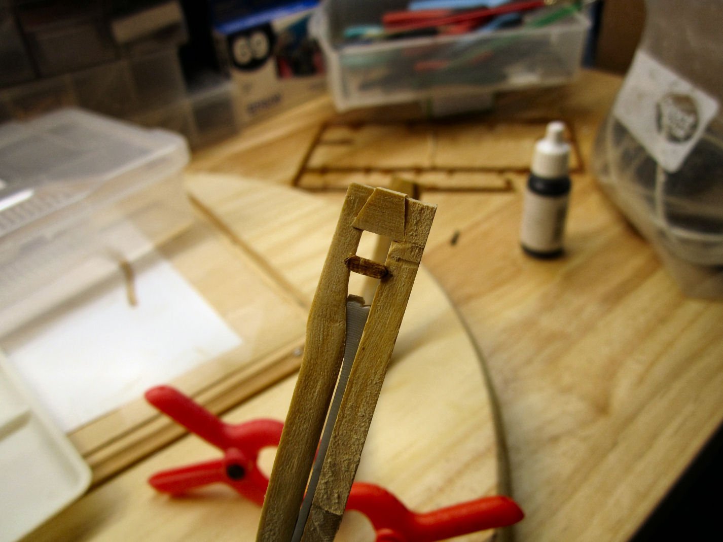
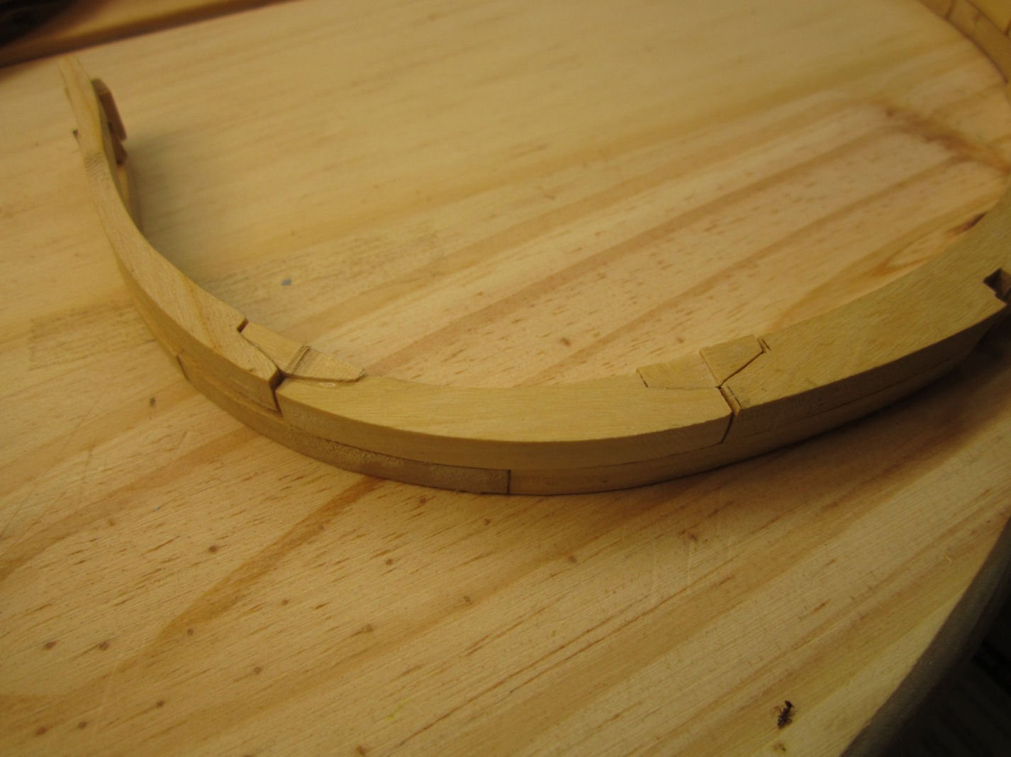
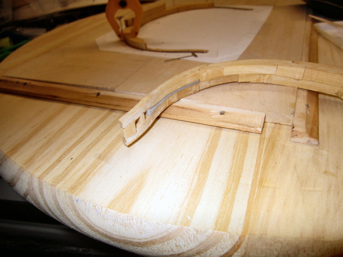
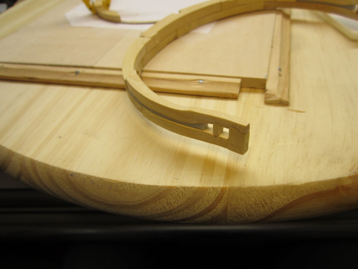
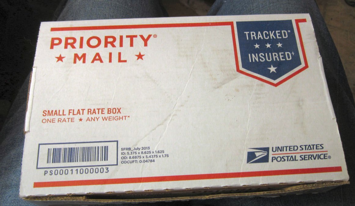
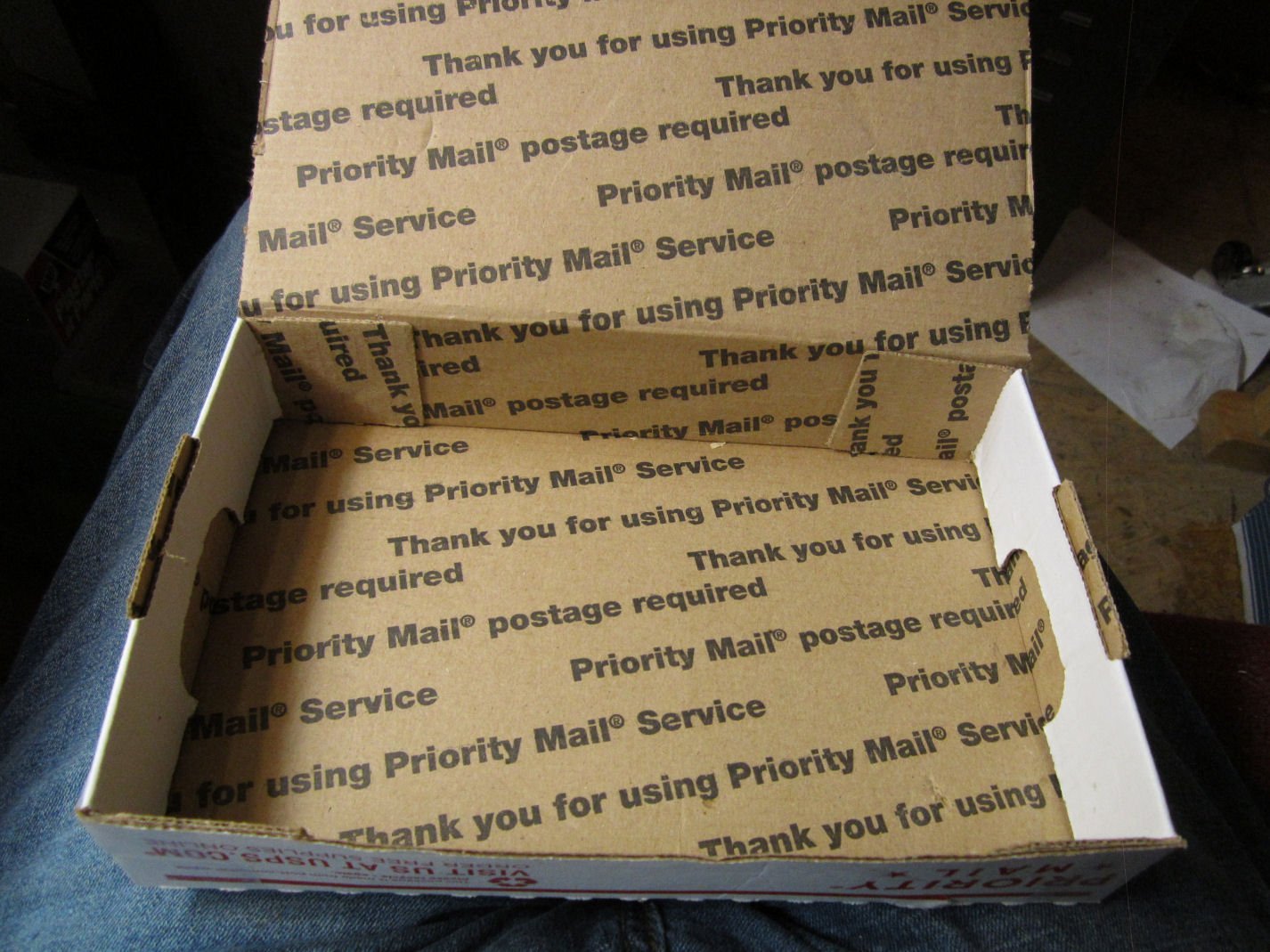
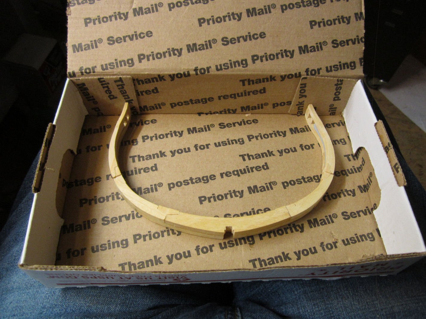
Part 010 Next I removed the resin inserts and trimmed off the heads, then reinstalled the tail pieces. I installed the larger of the blocks that tie the tips of the two halves together. Then I installed the thin piece, that goes below it. This is a laser cut plywood piece, and I had to sand bevels on each end so that they could slide into the groves in the frame. At this point I noticed that I had not sanded them enough and they had spread the frames a little (see the above picture). By that point, however, the glue had dried enough to prevent me removing them! I’ll have to break out my Jewelers Saw and cut through the center, which will hopefully remove enough so that the frames close up properly. Meanwhile, I cut the chocks down to match the level of the respective frame members. The photograph shows one chock cut and sanded (right hand side), while I have just started on the second one. For this I used an X-Acto Number 2 blade, small files, and fingernail sanding sticks. After the chocks passed the fingernail test (a fingernail passed across the surface does not catch on any protrusions at the joints of the surfaces), I sanded along the grain to hide the marks made cutting out the piece. After finishing the chocks on this side, I flipped the frame over and did the same to the ones on that side. I then used the saw to split the plywood pieces, On one side the plywood fell out as I was completing the cut. I glued the two sections back together and reinserted them. In the picture below you can see them right after I got them back in. I took a pair of flat surface needle nose pliers and used them to hold the two plywood sections into a flat alignment top and bottom (you can see that they are not aligned in the picture above). Once the glue had dried I faired the ends of the plywood pieces and the blocks above them down even with the frame surfaces. I also filed the top and bottoms of the plywood inserts to insure that those surfaces were lined up correctly. I managed to pop one of the other joints in the frame while doing this, but in the end, I finally finished this frame! Next I started to look around for something to store the frames in, as I finished them. In the end I found a simple, cheap, way to do this. I had a beat up one of the small Post Office Flat Rate Boxes laying around and when I folded it up, it was an ideal size. The box is designed to be held together, once folded up, when the tab on the top is glued to the front of the box. As I was going the not glue the top down, I glued the corner tabs in place then folded the side ears down and glued them also. After cutting the ears off the sides of the top, I had a nice frame holder! It is large enough to hold two frames in each layer, if the second frame is set in upside down so that the bottom of the frame spans over one tip of the first. It looks to be deep enough for three layers (6 frames total) of frames per box. At this point, in time, I have also finished Frame 7, and will detail that in the next part. Before starting on the next two frames (7 & 8), there are corrections to the instructions needed, so stay tuned, (or go to John H’s review of this kit, where he details the corrections)!

- 38 replies
-
- 12
-

-
Welcome!
-
Now there's a Man's Man! I was expecting the whole thing to go sprong, at the end!
-
Just a note: In the pictures of the Old Way, there were 4 cross slates on the bottom. In the New Way there are only 3.
- 24 replies
-
- 2
-
-
- lobster trap
- red baron
- (and 2 more)