thibaultron
-
Posts
2,951 -
Joined
-
Last visited
Content Type
Profiles
Forums
Gallery
Events
Everything posted by thibaultron
-
 I've turned all that off, already, the laptop still wants attention, regularly. Its old, and I guess lonely. Seriously, yes, I've corrected all those settings, but my laptop still needs me to move the mouse now and then. Thanks though!
 -
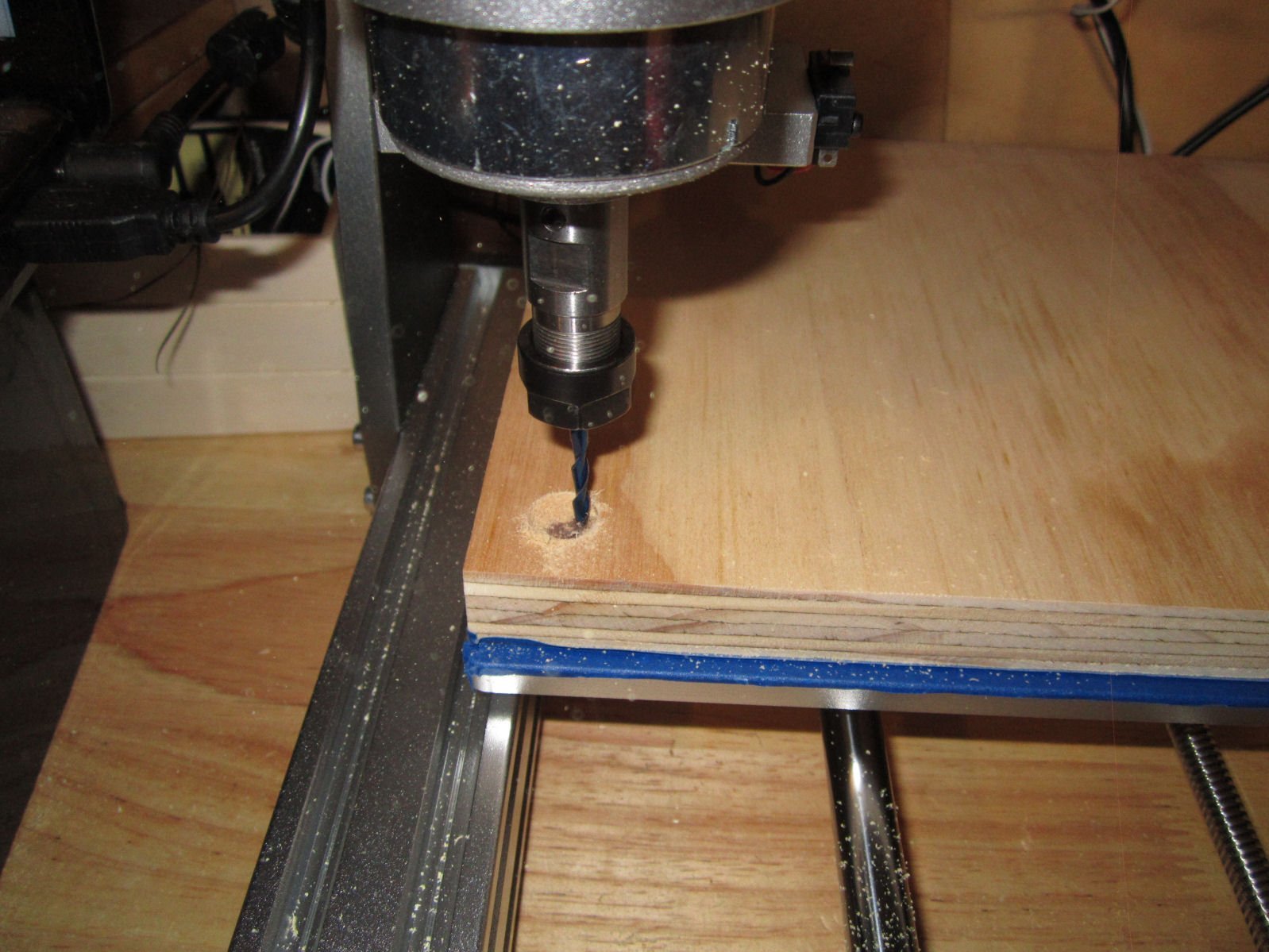
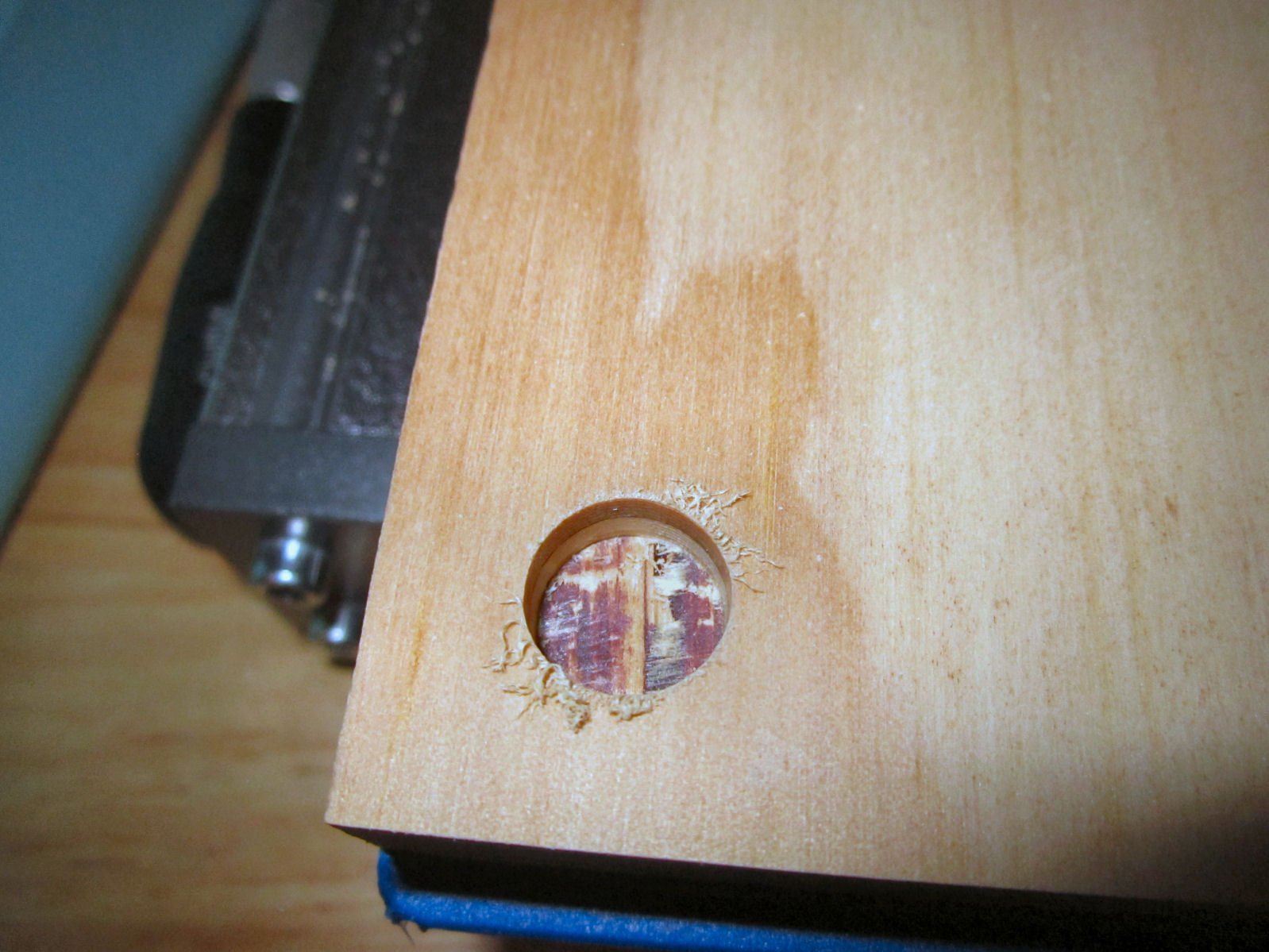
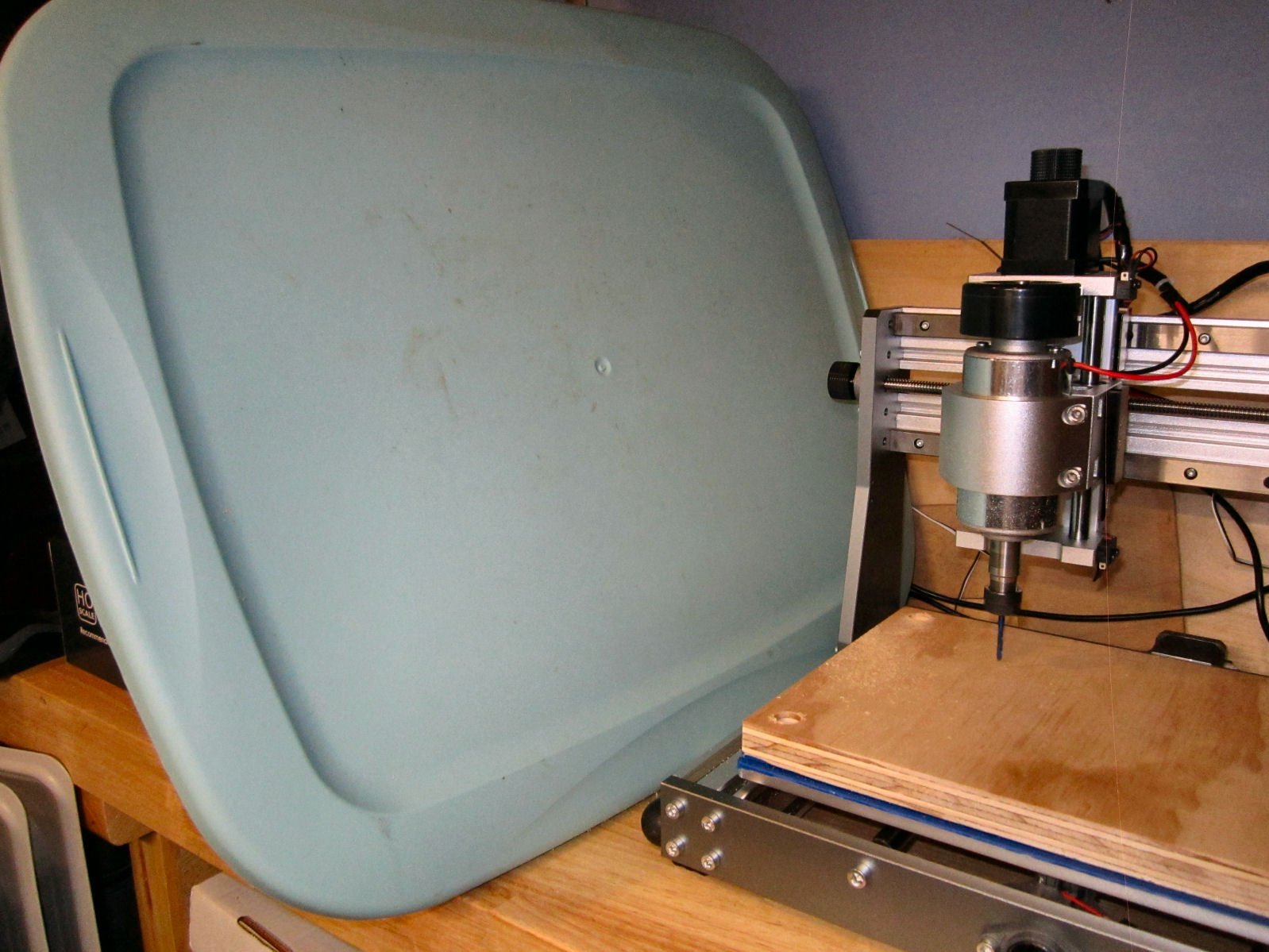
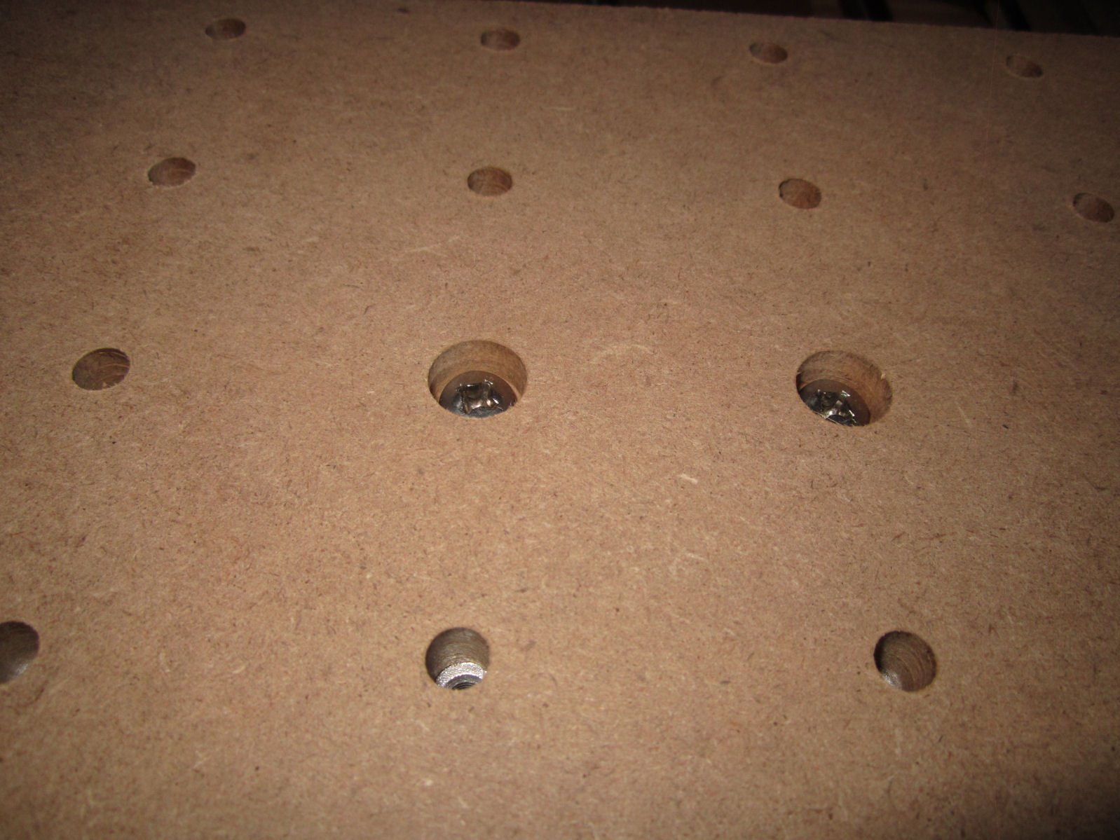
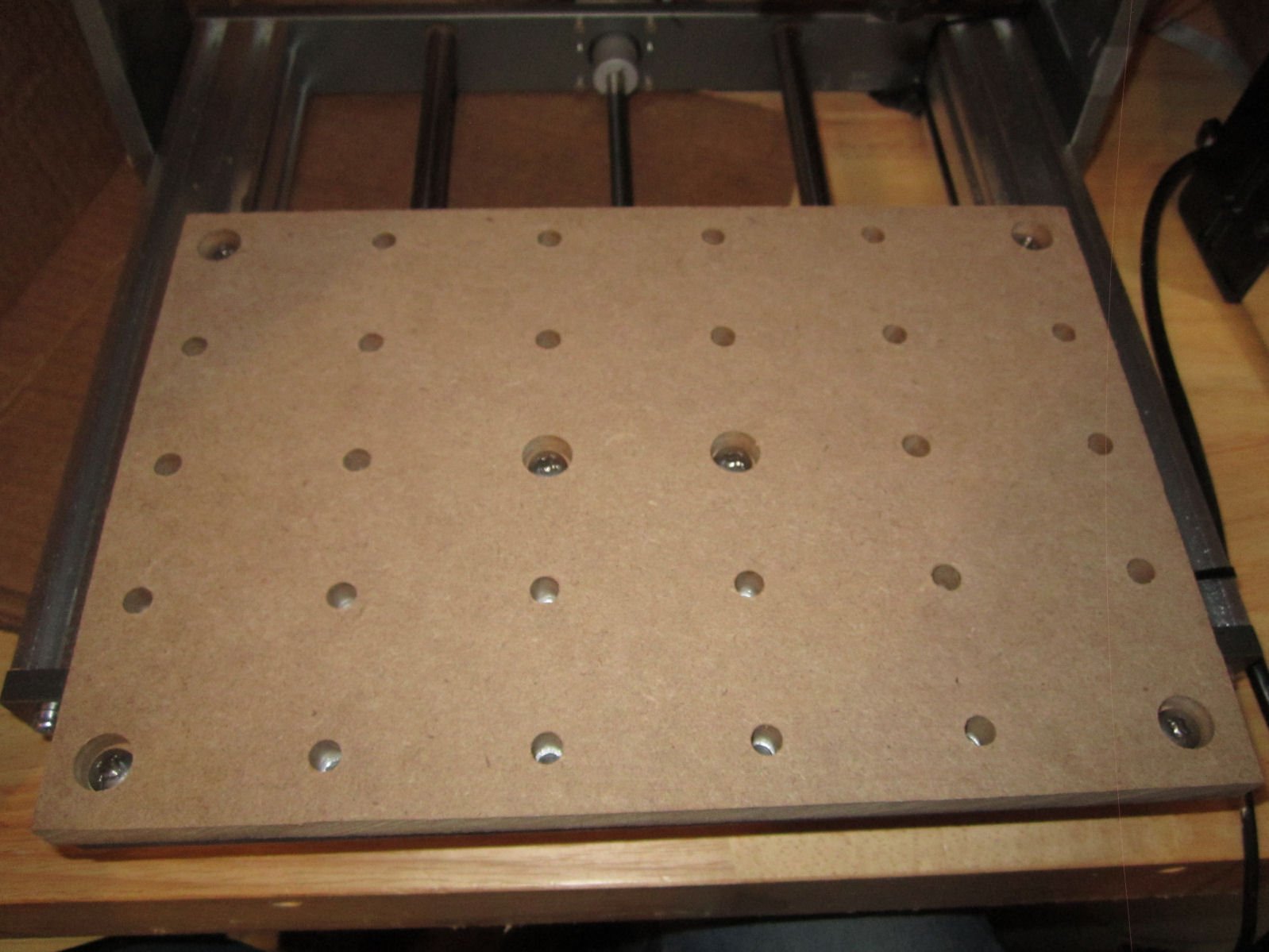
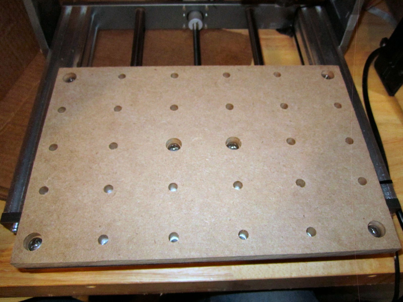
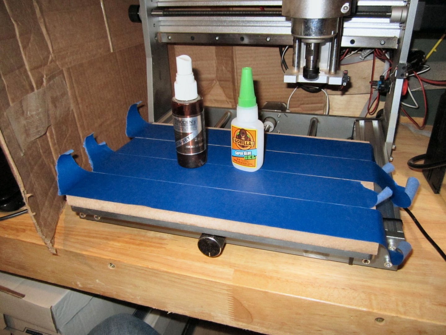
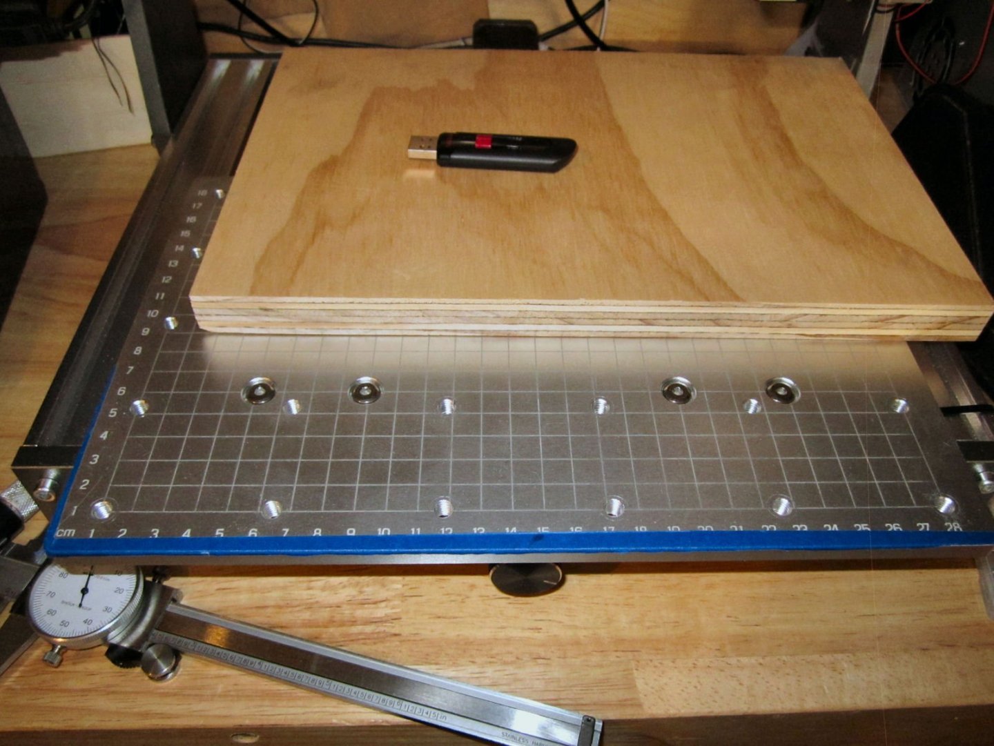
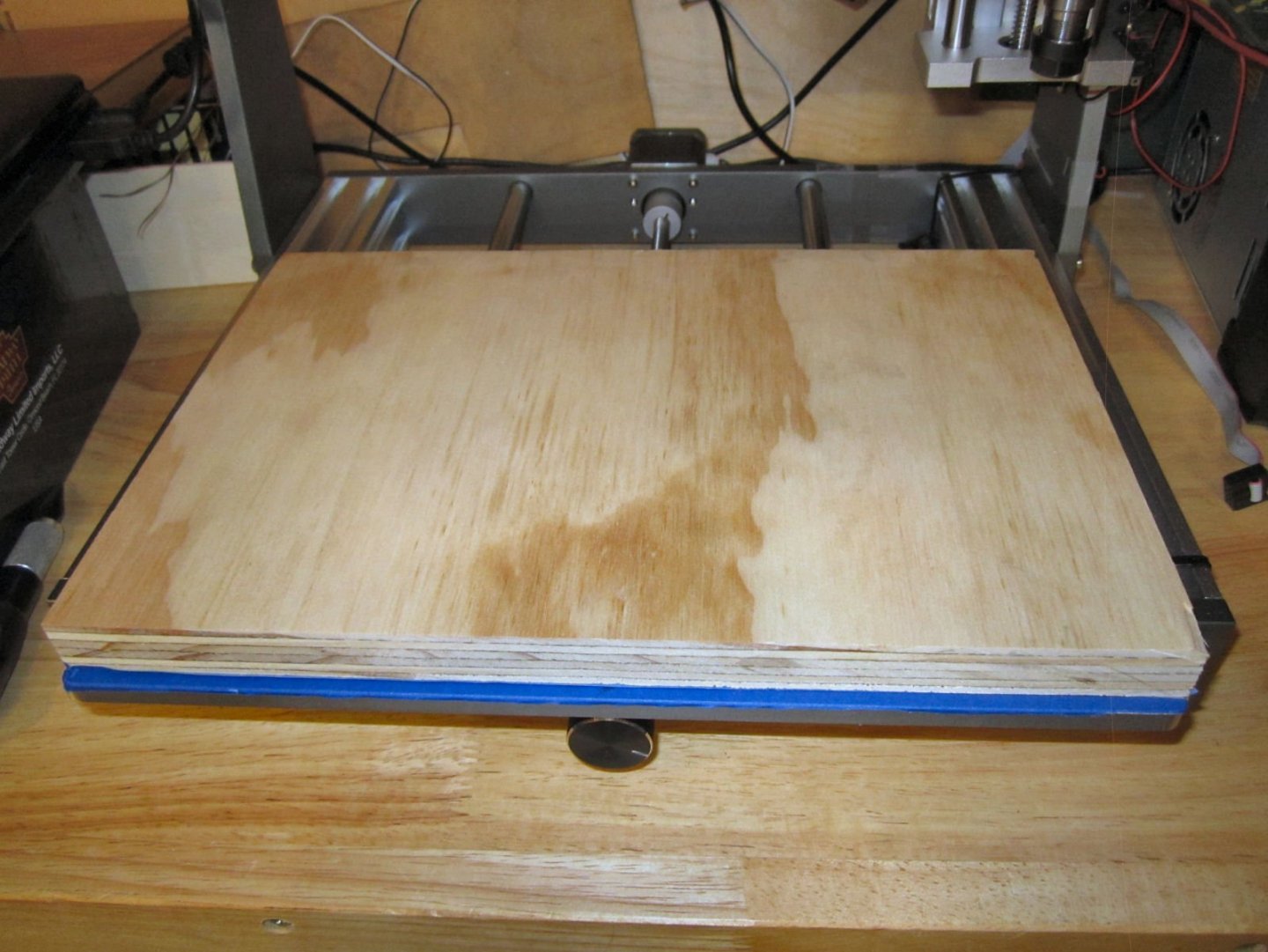
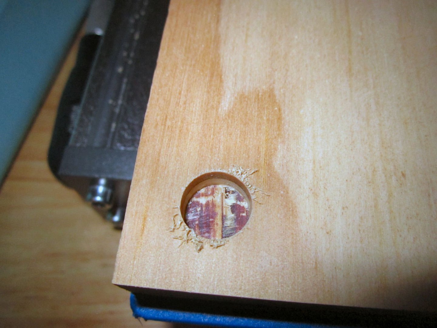
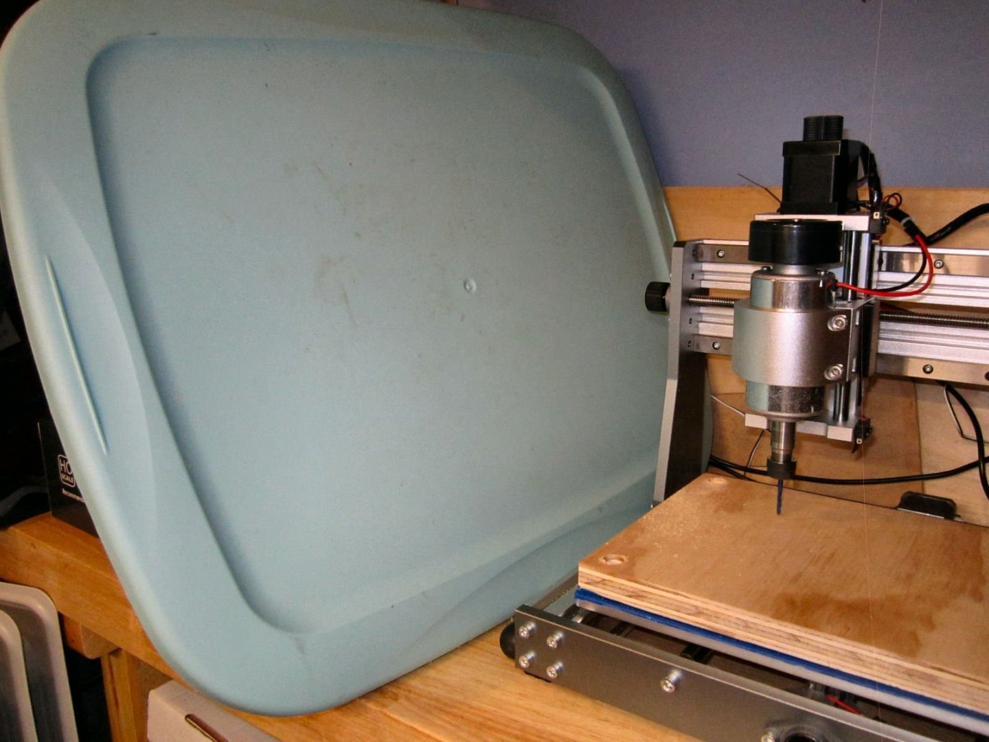
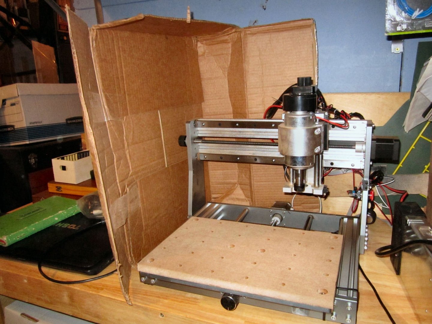
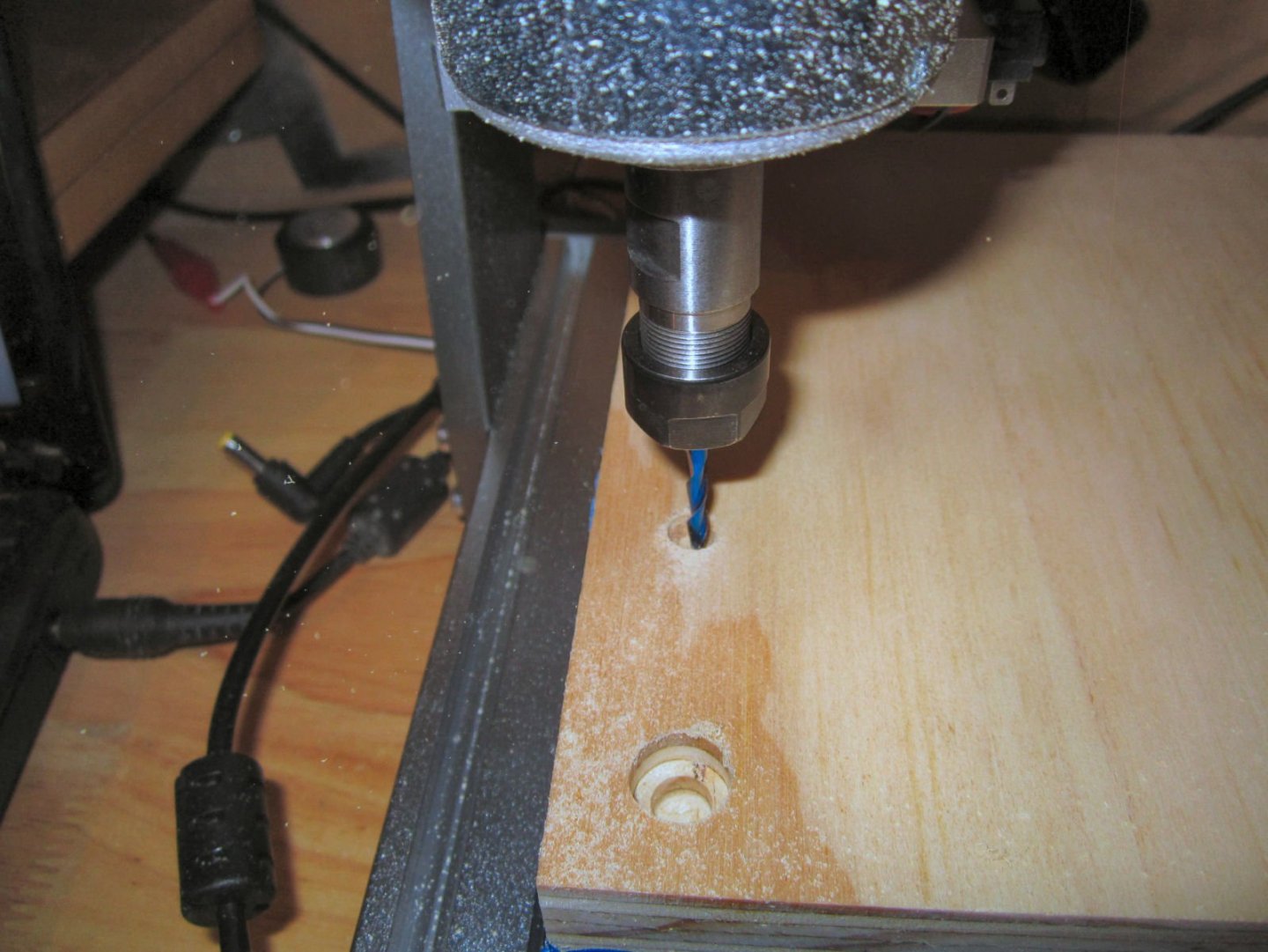
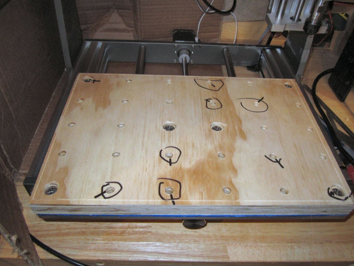
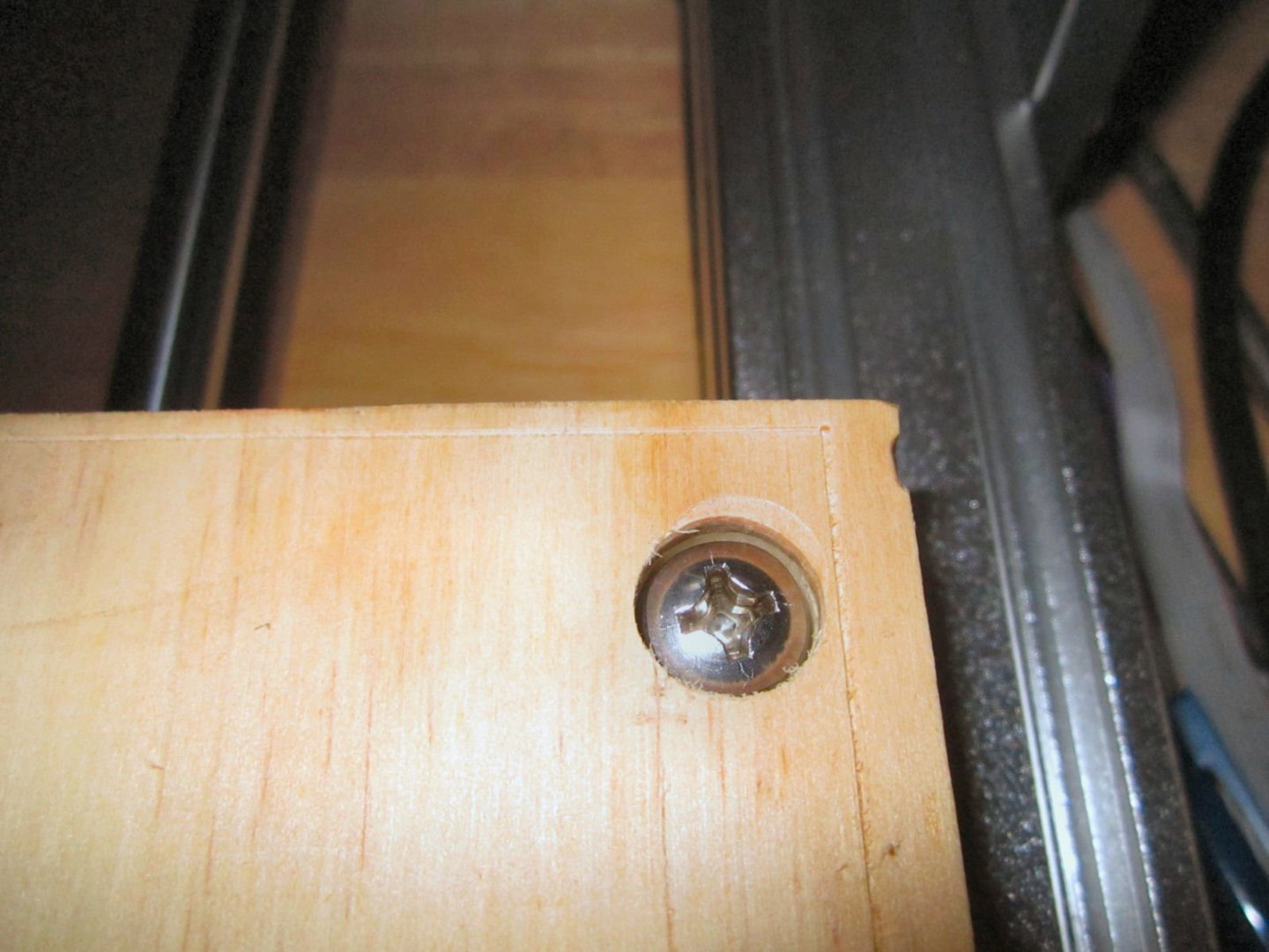
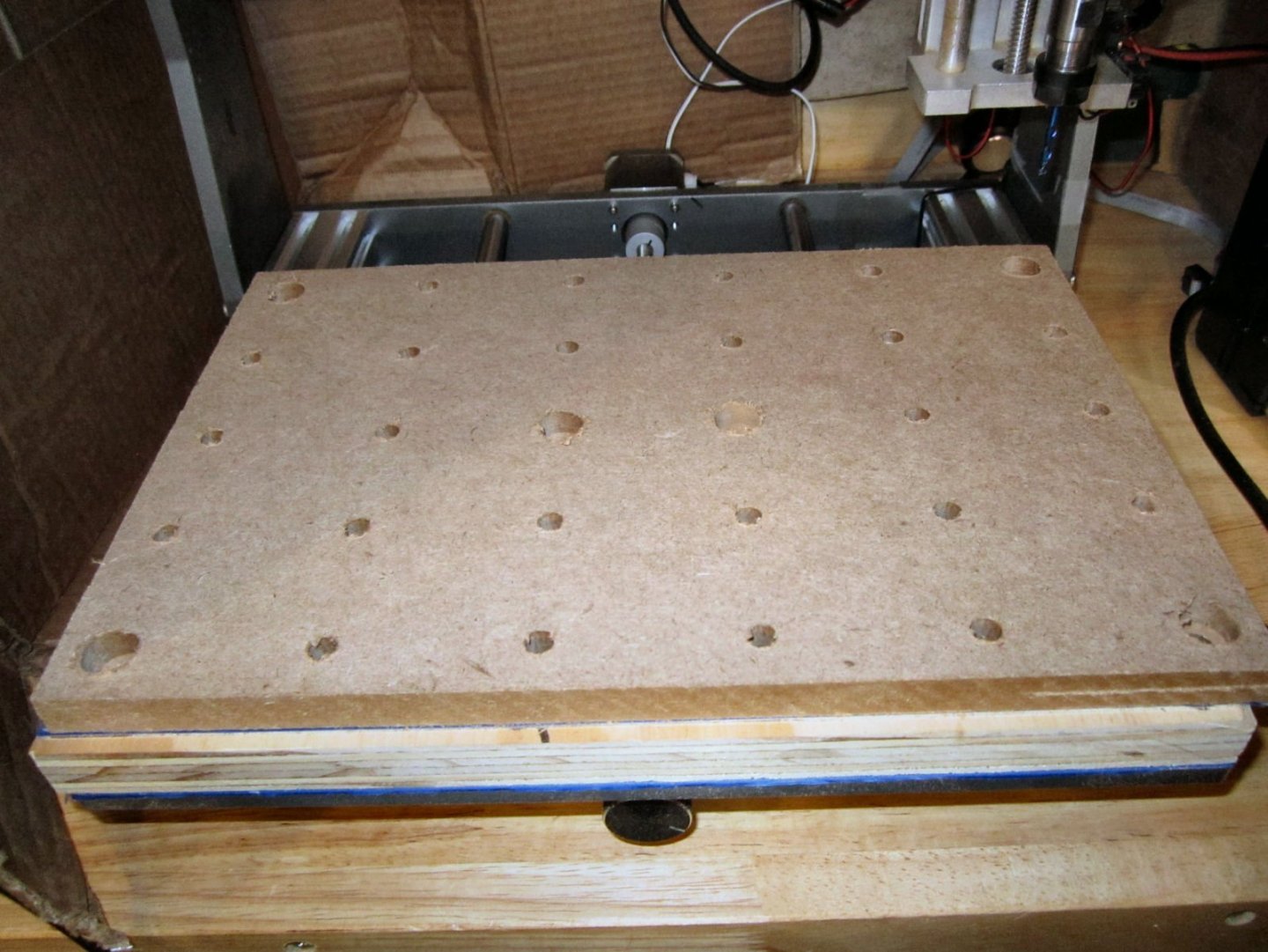
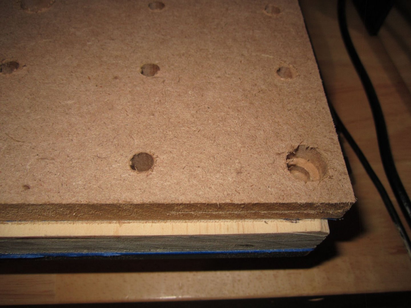
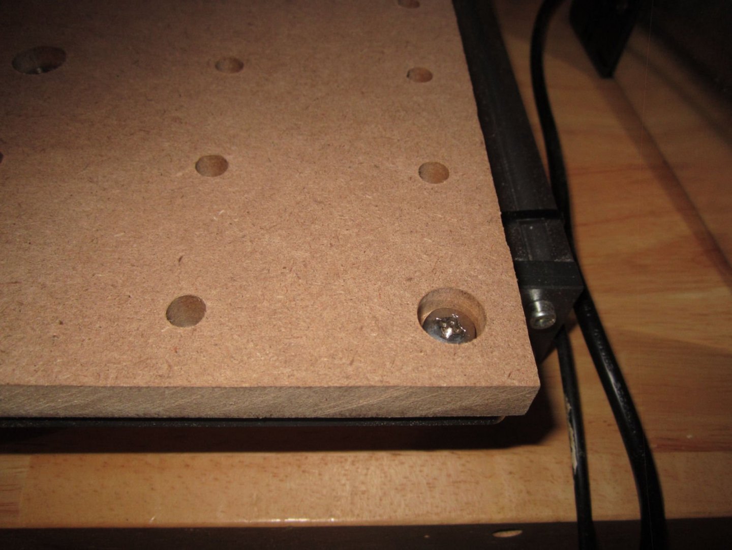
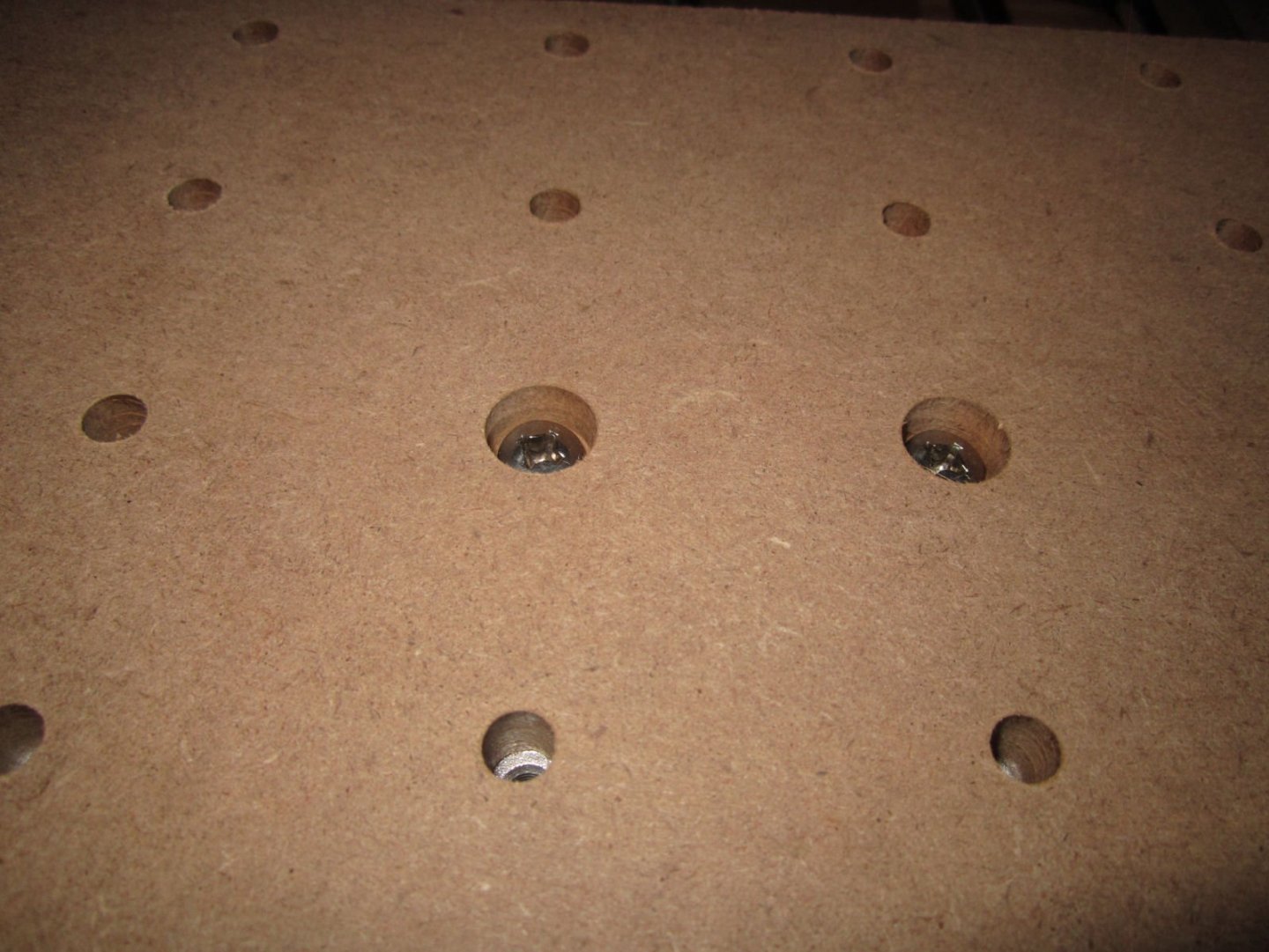
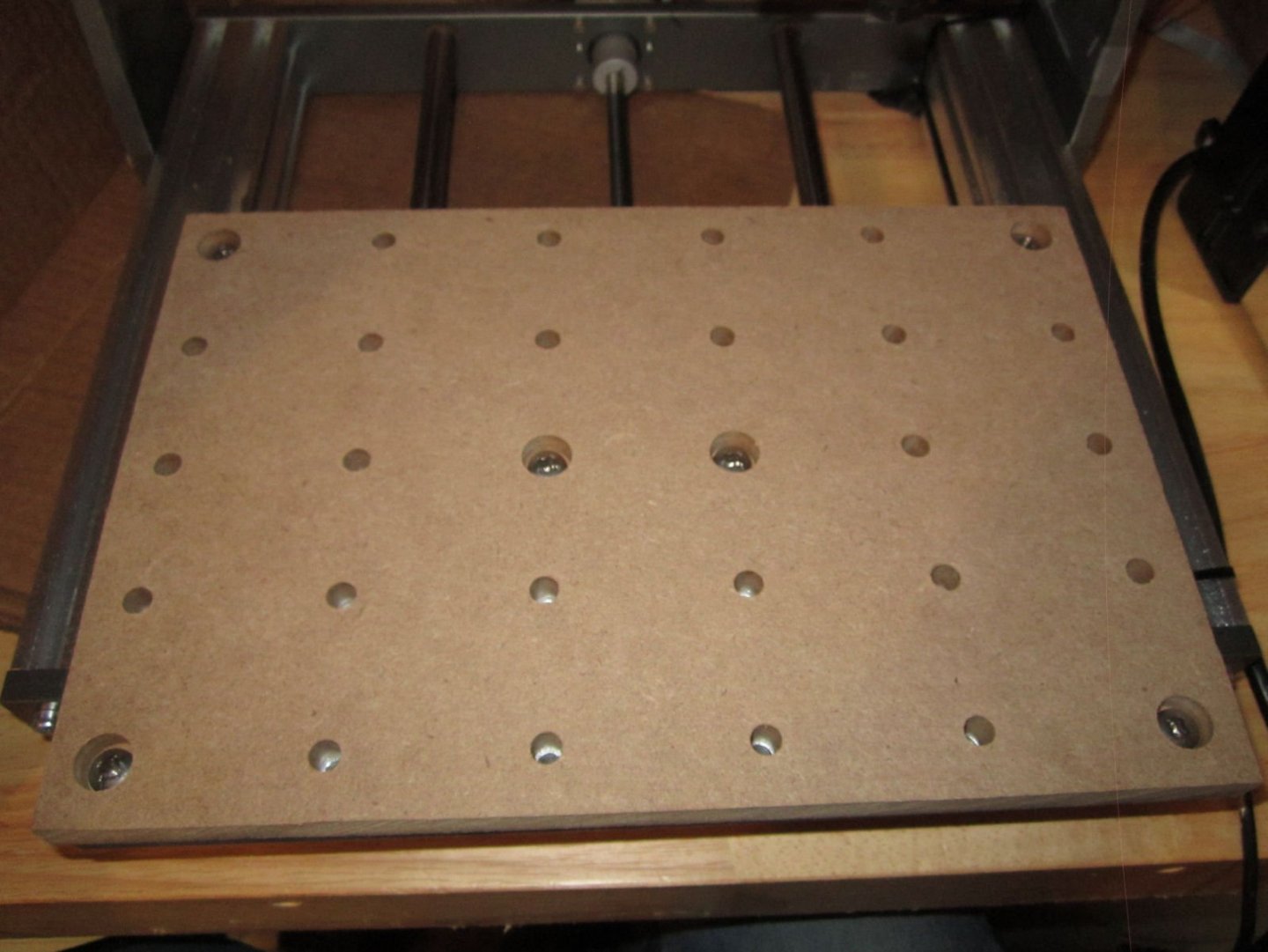
Part 13 Finished the first spoil board for the 3020. It was a long road with a lot of learning curve (software design and cutting, as well as hardware). I used the 30 day Easel CNC Pro trial version to design the spoil board, which I’ll detail later. The only Pro feature I used was the Ramped Cutting one. This starts the cut at the level of the finish of the last step and ramps the cut down at either 5 or 20 degrees, to get to the next cut depth. Most of the cutting bits available for these machines cannot do plunge cuts (drilling type). The ramp allows the bit to cut down at an angle, reducing the stresses over just cutting directly down to the next depth. I’ll have to redo the design in CarveCo, once I learn how to use it. I’ve found the best way for me to learn such software, is to just go ahead and design something, so that is not a problem. At least I know that all the holes are in the right spot. One thing I will have to change is the depth of the cuts for the through holes. I’m using ½” MDF, so I set the depth at 12.7mm. Unlike modern plywood in the US, which runs 1/32” thinner than the standard old dimensions, my ½” MDF seems to be slightly thicker than ½”, and the holes did not penetrate all the way through. The standard design for spoil boards for this size machine is one ¼” thick, held in place with the Blue Tape and Superglue method. That method has you put a complete layer of Blue Painter’s Tape on the bed and bottom of the work piece. The tape strips are placed as close to each other as possible, without the edges overlapping. You then run a bead of superglue down the center of each strip, on the bed, and spray glue accelerator on the tape on the work piece. Then you carefully align the work piece and press it down. The tape holds well enough to both parts to provide a good attachment for most cuts. After you are done, you pry up one corner of the workpiece with a chisel or screwdriver. This breaks the tape’s hold, and you can pull off the workpiece. Then you peal the two superglued layers of tape off of the bed. The picture below shows a quick example of a layer of tape applied to the finished spoil board. Normally I would not have that exposed section on the right, and I would have trimmed the loose ends. Next time I will buy thick superglue, not the Gel type shown. The gel type is very hard to get to the tip of the bottle. I have to bang the tip (with the cap on, of course) on the table several times to get the glue to fall into the tip area. I like this method for work pieces, but would prefer to bolt the spoil board to the bed. I’m not going to be using the machine as someone would for a business, so the spoil board will not be changed as often as if I was running it 8 or so hours each day. Thus if I used the tape method it might have to survive months between board changes, not weeks. I don’t trust the tape bond over a long time span. Thus to allow for the bolt heads, I went with the ½” MDF. Anyway, the design is for a ½” thick MDF spoil board held down with 6 recessed screws, one in each corner and two in the center, with 30 holes drilled to match those in the bed. The corner holes and the two center holes are not that useful as hold downs for the type of clamps supplied with the router, so the bolts occupying them should not greatly affect the clamping ability of the spoil board. Below is a picture of the finished spoil board to this point (milling it flat, later, will be the final step). I found that the software limit settings did play an important role in cutting this board. The Easel CNC software defaults to the origin being the lower left corner, rather than the machine’s upper right, so I ran the tool to the bottom left corner, using the limits to set that location. There may be a way to change this in Easel, but I decided to just “Go with the flow.”, for this first design. I’ll detail the design process in a later post, as well as when I redo it in CarveCo. I designed it using the 30 day trial version of Easel Pro. Unfortunately due to preparing for, going on a weeklong Thanksgiving vacation, and doing all the normal activities skipped at home during same, I was delayed in starting the board for 3 weeks. I finished cutting the boards below and making the last correction 6 hours after the trial expired! This means that the ramp function was removed from my final version of the files, thus the need to redo it in CarveCo. I started with the design cut into a piece of ¾” plywood. This gave me some added margin of error, if I accidentally set some cuts too deep, or some other problem cropped up. I ran the spindle to the lower left with a “V” bit installed to show me were that “0” location was, and placed tape along the edge of the bed to help me align the work piece. I clamped the plywood using the blue tape method (above), and started the machining. There were a number of problems I ran into: 1. My first laptop developed a severe heat problem, and eventually died. Luckily I had an older laptop, and was able to switch my hard drive over to it, and continue. 2. I have not built a case for the machine, and the laptop is sitting next to the router. This was depositing a fair amount of sawdust onto the computer! 3. Vacuuming the sawdust off the computer while you are cutting, is a pain, especially if you accidentally hit the power button, while doing so, shutting down the computer in the middle of the job! 4. Pausing the job in the middle, due to the Admiral calling you off to do something else, doesn’t work, at least with my laptop! The job was locked up both times I tried it. 5. You have to babysit the router the whole time it is cutting, as Murphy dictates that bad things will happen as soon as you step away. 6. You have to periodically vacuum up the sawdust/shavings, anyway. 7. Don’t accidentally hit the power switch on your power strip with the vacuum cleaner hose while the job is running, either! 8. Having to restart an hour or two long job, halfway through due to any of the above problems, is really aggravating!!!! 9. Enclosure needed! Cutting MDF left me covered in a layer of MDF dust, even with regular vacuuming! 10. It is safer to move the mouse every few minutes to make sure that the laptop is not turning anything off. 11. Don’t try doing anything else on the computer (at least an older one like this), as the G-Code program may crash! It apparently uses a lot of computer resources! I did find that returning the machine to the starting point (sometimes several times) was reliable, at least. I set the cutting speeds very conservatively, so the jobs probably could have been run in shorter times. I read that the router should be creating chips not sawdust, otherwise you can overheat the wood or the cutter. My settings were mostly making sawdust. I checked after the finish of each job, and the bit was not heating up, though. I cut the clearance holes first. The first solution I tried to keep the sawdust off the computer, was to place a storage tub top between the machine and the laptop. This worked, but blocked my view of the computer screen, and access to the mouse. I found an old box and cut it to use as a block. This worked well as a temporary measure. After the clearance holes were finished, I cut the through holes. I had cut the through holes in the plywood 12mm deep, planning to drill them the rest of the way through, using the existing holes, as a guide. This would have worked, if my drill press was not presently buried, trying to do this by hand allowed the holes to wonder, and many of them did not clear the bed holes. This did show some errors in the design, that I was able to correct for the final design, though. Another problem I found was that the screw heads were thicker than I had thought, and I deepened the clearance holes by another 4mm, to give more clearance for miscuts, during regular use. In the future I will grind the tops of the bolts down some, for added clearance. Presently I have about 5/32nds” (4mm) of clearance between the top of the screw and the surface of the spoil board. I’d like to get that up to ¼” (6mm). This is a shot of the first version of the finished plywood board, I later cut the clearance holes deeper, for the added clearance. The black marks indicate where the drill holes wandered off center, blocking the bed holes. This is one of the screws installed. I used a “V” bit and ran the machine by “hand” from the computer, to mark the limits of where the tool bits can cut. See the lines by the screw head above. Using the lines on the ¾” plywood, for alignment of both the “0” position, and getting the board square, I mounted a piece of ½” MDF and cut my first spoil board. As I said above, the through holes did not go all the way through, but I only had to drill out a thin skin to complete them. After sanding the top and using a large flat file to get rid of some slight existing ridges around the holes (top and bottom), I mounted it, with 12mm long 6mm screws. The final step will be to use a 24mm flat bit to mill the spoil board surface flat and parallel to the bed and spindle. I found a canned program to do this, but it runs into problems with the software limits. I’ll have to investigate this further, or design my own program.

-
I'll post more later, but I just finished cutting my first Spoil Board today! Has all 30 holes for the clamps with 6 of them recessed for machine screws to hold it down. I still have to create a program to mill the top flat, but have been struggling with Software Limit issues. Even a canned routine will not run. More to figure out. The board is 1/2" MDF, rather than the standard 1/4", to allow for the screws. I don't like the idea of holding the board down with blue tape for long periods, as even Blue Tape will leave deposits after an extended period.
-
Easel CNC assumes the 0,0 point is at the bottom left corner (like regular Cartian Coordinates). So I always have to move the 0 when using Easel. I'm just starting with CarveCo, and haven't drawn anything in it yet.
-
Thistle, your limit switches should have stopped the travel, before the mechanical limits were reached. My problem was only with the software limits. Any G-code software problems should not effect the hardware limit switches! Run the table by hand and test that the switches, actually activate, before the mechanical limits are reached. Also make sure that you have at least a few mm of clearance after the switch activates, to allow the whole system to physically stop, when running full out, and for the fact that switches have a tolerance for activation. The limit switches that are supplied with the 3020, have about a + 0.008" tolerance.
-
Part 12 OK, the single X and Y-Axis limit switches are not enough! I have to contact SainSmart again about getting a set of matching limit switches and mounts. It turns out that the Software Limits are only effective, if you never change the “0” positions of the axis. You have to do this for most jobs, as you have to set the axis “0” to some position over whatever chunk of workpiece you want to carve. Once the “0” position is changed the soft limits go out the window, and the machine will happily go past the mechanical limits, as the total available travel is no longer “X”, it is now “X- however much you moved the origin.”
-
Years ago I worked in a computer lab, with a raised floor with removable 2X2 foot "Tiles". You lifted the tiles to run cabling underneath the floor. The tiles had blue carpet squares glued on top. Over the years many carpet squares came loose, making the floor look bad. Our boss convinced the company to replaced them. They choose a multi colored earth tone "Where the h..l did did that part go!" pattern for the new carpet squares! After they finished we and the boss wished we had just kept quite about the floor!
-
Magnifiers and glasses
thibaultron replied to Dave_E's topic in Modeling tools and Workshop Equipment
Yes, I've used mine for that more times than I care to admit to! -
Be careful of that heater plugged into the power strip! My friends had the cord to their's catch fire 2 weeks ago! Thankfully they caught it in time.
-
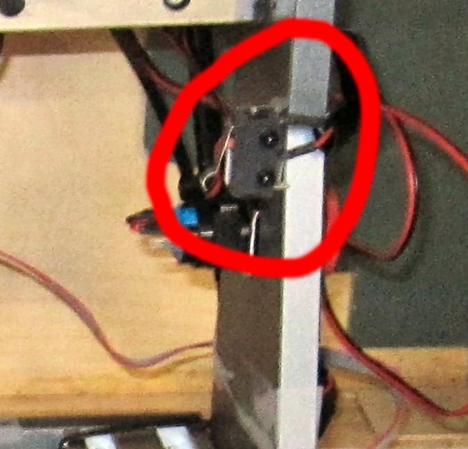
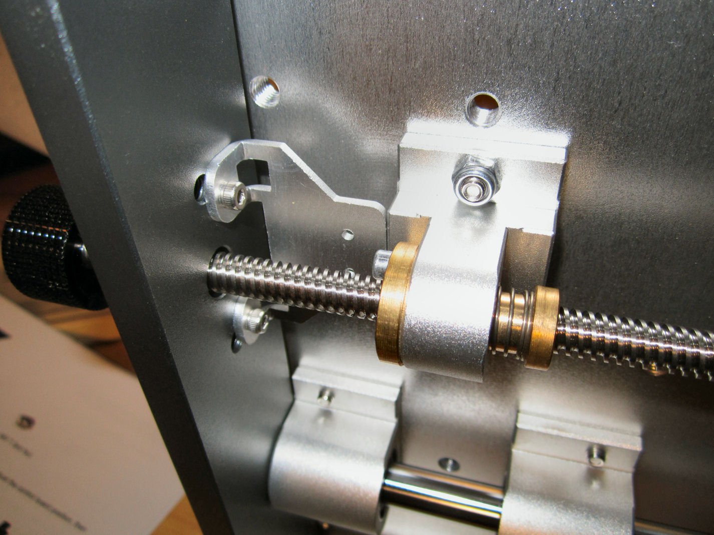
Part 11 Ran into a problem yesterday. The Z-Axis mechanism was locking up during the "Homing" operation. It was mechanically locking before it contacted the upper limit switch. The stepper motor was buzzing loudly as it was still trying to turn the feedscrew. I couldn’t see any debris in the slot at the top back of the feedscrew nut. Then I noticed that the coupling nut looked like it was lower than it had been. The other coupling nuts sit in a depression in the frame that puts the set screw for tightening the servo end of the coupler partially below the frame surface. Thinking that the nut for the Z-Axis was the same, I took the assembly apart. Nope! It turns out that the coupler hits the top of the seated feeds crew, before the nut gets that deep into the upper frame/motor mount! ###....####. While putting everything back together was not difficult, and the parts seem to slot nicely together, I hope that nothing is just slightly out of factory alignment. After running the feedscrew, by hand, until the slide was mostly at the bottom (being careful to hold it off the limit switch), I Then slid the coupler back onto the servo shaft as far as it would go, and tightened the clamp setscrew. The slide now cycles correctly. I also had removed the spindle motor during the disassembly, and I had noticed that the wires had sagged and were touching the frame, during cutting. So I turned the motor to put the wires from the motor to exiting from the right, as shown in the instructions. This seems to help. I have been using an old piece of Particle Board (as opposed to MDF) for my trial cuts, and I have broken 2 20 degree “V” bits in short order. This is a very old chunk of material (at least 25 years old) and may be of different composition to modern stock. In any case I would not recommend using Particle Board on this machine with “V” bits. I’ve purchased both ¼” and ½” MDF boards, and will use these from now on. I’ve also found that the “V” bits stick into the aluminum top surface of the Z-Probe when using it (deep enough that the probe will raise off the workpiece when the slide is lifted back up). This gives a false height, naturally, and mars the probe surface. It use the slip of paper method for setting the “V” bit height now. I have not used any of the other types of bits, and will report on them, when I do.
-
Shipping Pallet patent November 1939, so it would be correct for 1940.
-
Metal Lathe - 1. A device for throwing chuck keys at your face. 2. A device for throwing large semi round workpieces at your body, because you forgot to completely tighten the chuck (reason chuck key was still in the chuck). 3. A device with a lot of heavy chucks that fall on your feet, during changing.
-
As you can see in the last picture of Part 11, I was incorrect about UGS having Jog buttons! The "Jog Controller" button opens the Jog button window, unless of course, you've accidentally clicked the "X" in the Jog Controller window! In that case it disappears, and I haven't been able to figure out how to get it back! ***,,,****! jog
-
Clare, what is your stain formula?
-
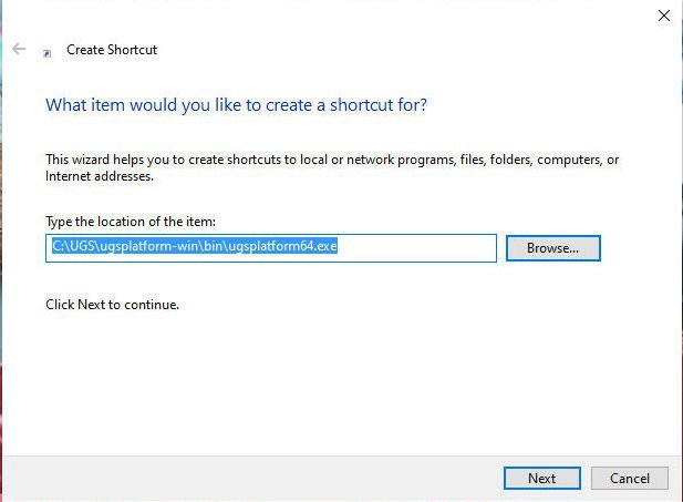
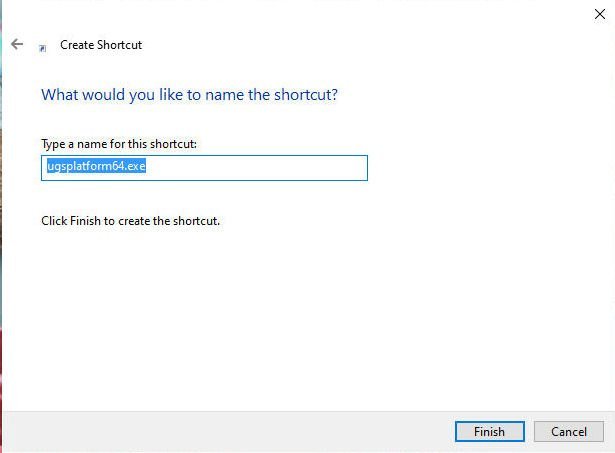
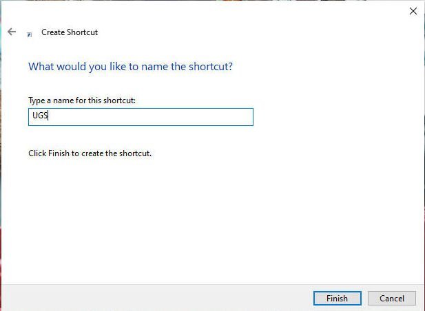
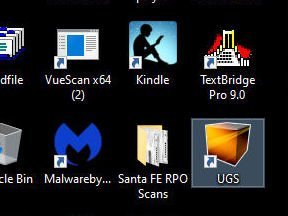
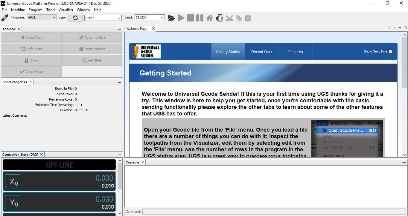
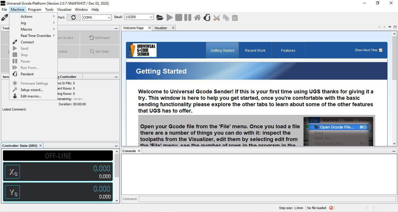
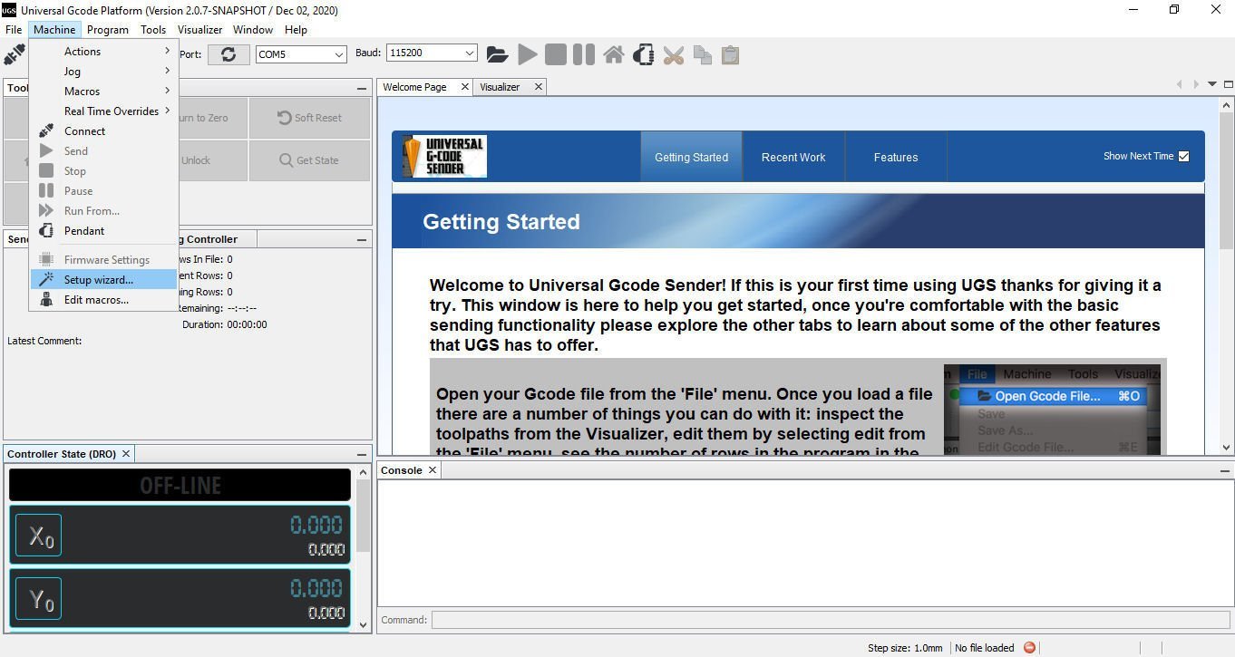
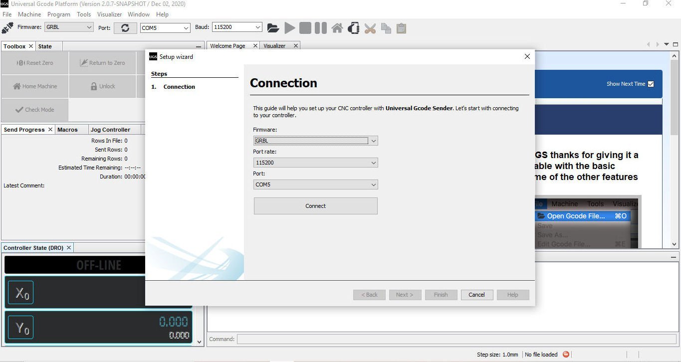
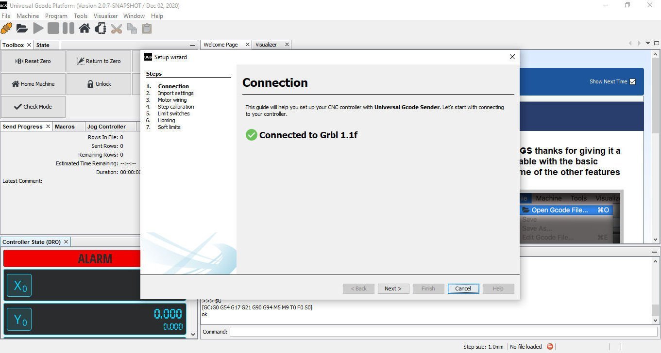
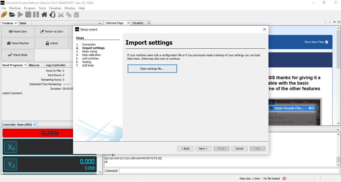
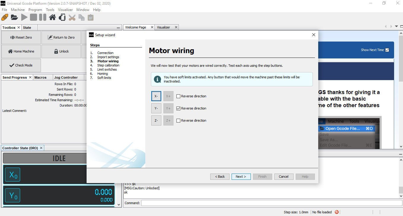
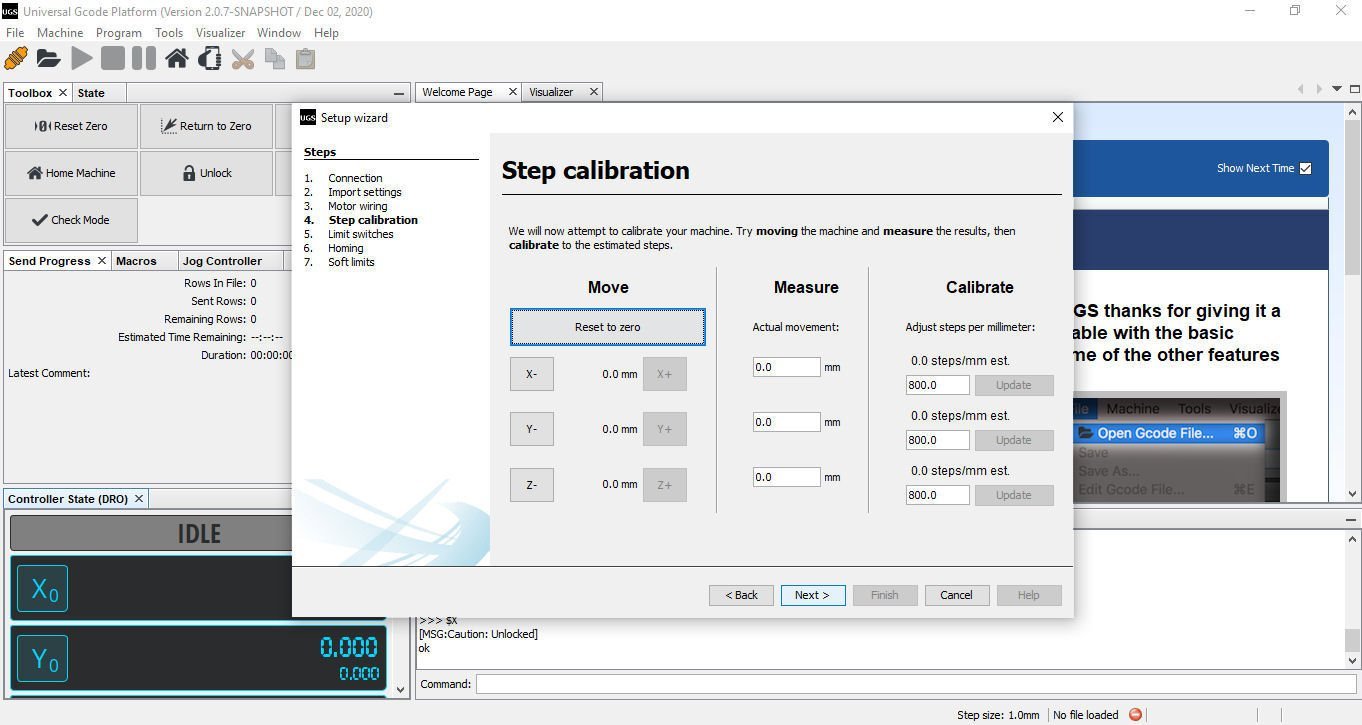
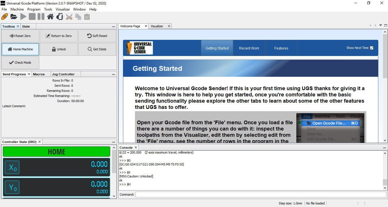
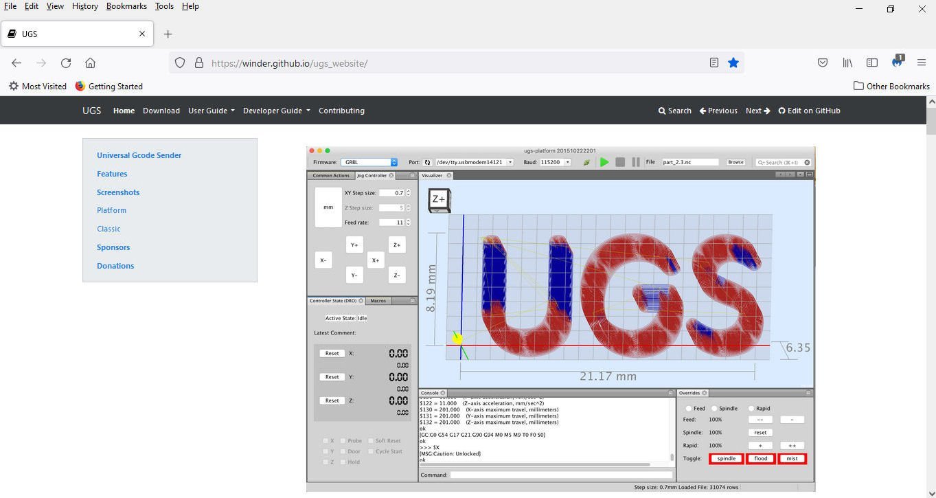
Part 010 With the bin directory open select which of the two program .EXE files you will be using, then “OK”. This window will open. Select “Next” and this window will be displayed. You can leave it as shown and select “Finish”, but the name “ugsplatform64.exe” (in the example above), will be the name displayed under the icon. I typed in “UGS” instead. Select “Finish”. This is what the icon looks like on my Desktop. I was mistaken in an earlier post. UGS does not have a “keypad” that allows you to move the various axis back and forth, like Grblcontrol does. It does allow you to “Home” the machine though, so you can make sure you are connected. Turn on your machine. When you start UGS, this window will be displayed while it is loading. Once loaded this screen is shown. The program was already installed, so you see it after I had set the Com Port. The first time you run the program you will have to setup the Com Port. Select the “Port:” button and the software will search for available ports. Select the port you recorded earlier. Next Select the “Machine” menu item, and then “Setup Wizard..”. When the Wizard opens, check the port setting, and select “Connect”. You should get this acknowledgement. Select “Next”, and the Wizard will go to this step. I was unable to find any configuration files on the SainSmart thumb drive, so I selected “Next” to skip this step. The next window checks that the Axis move in the correct directions. Follow the instructions. My machine behaved correctly. After checking your machine, select “Next”, and you will go to this step. As I was not ready to do the following steps yet, I selected “Cancel” and went back to the program. I selected the “Home Machine” button, and the router went through the Home routine correctly. I stopped at this point, as I don’t have any scrap to test any of the files on right now, but at least I know the software talks to the router. When you start the program after this, you have to open the “Machine” tab and select “Connect” to connect to the machine, before running anything. Part 11 will be about the GRBL Candle program included with the SainSmart software.

-
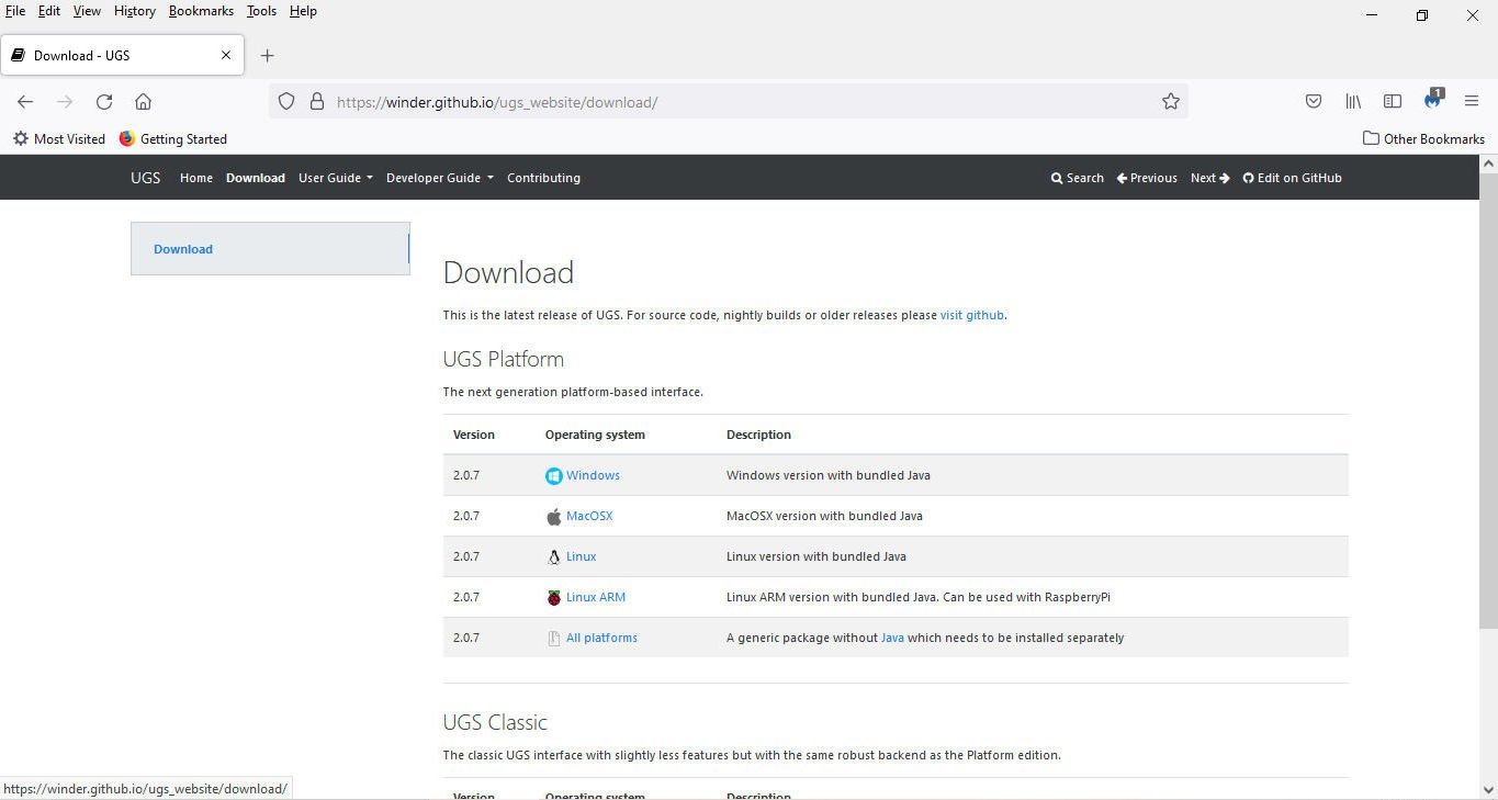
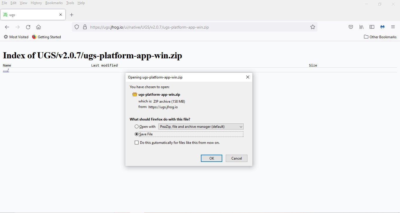
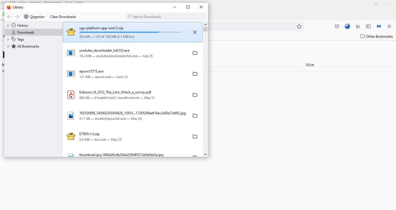
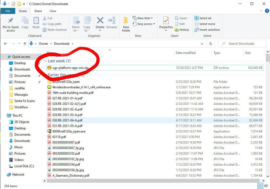
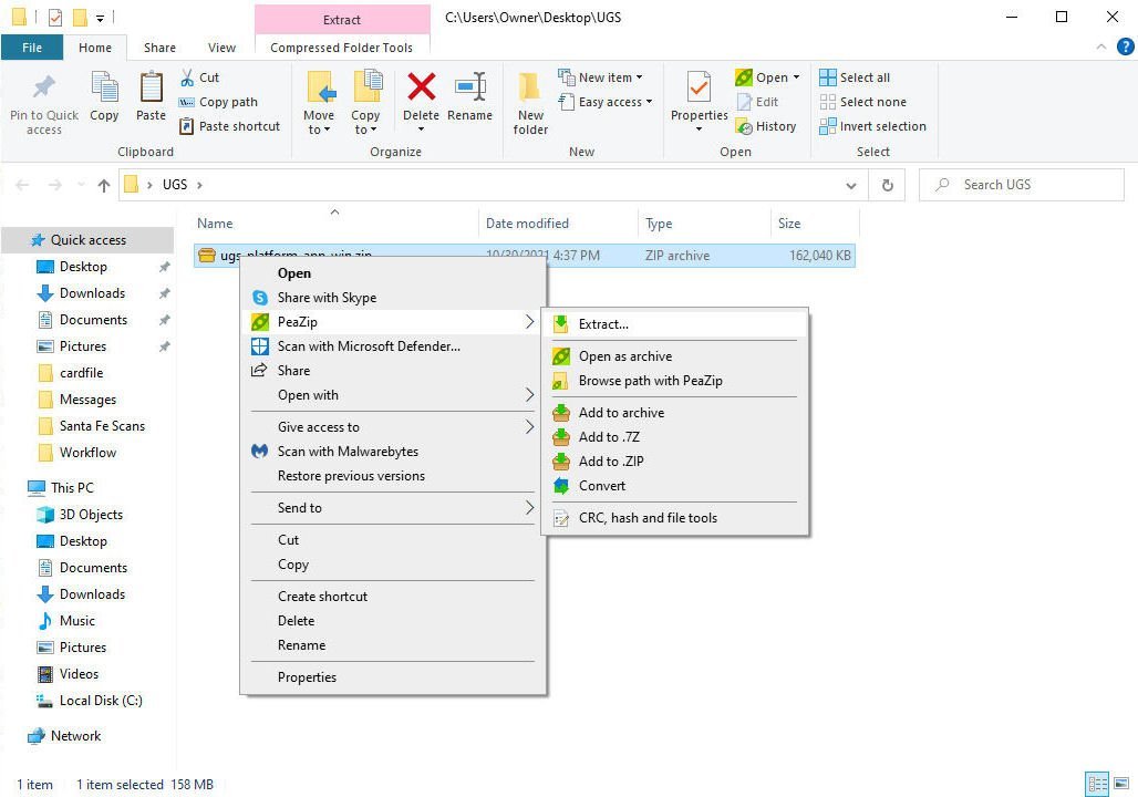
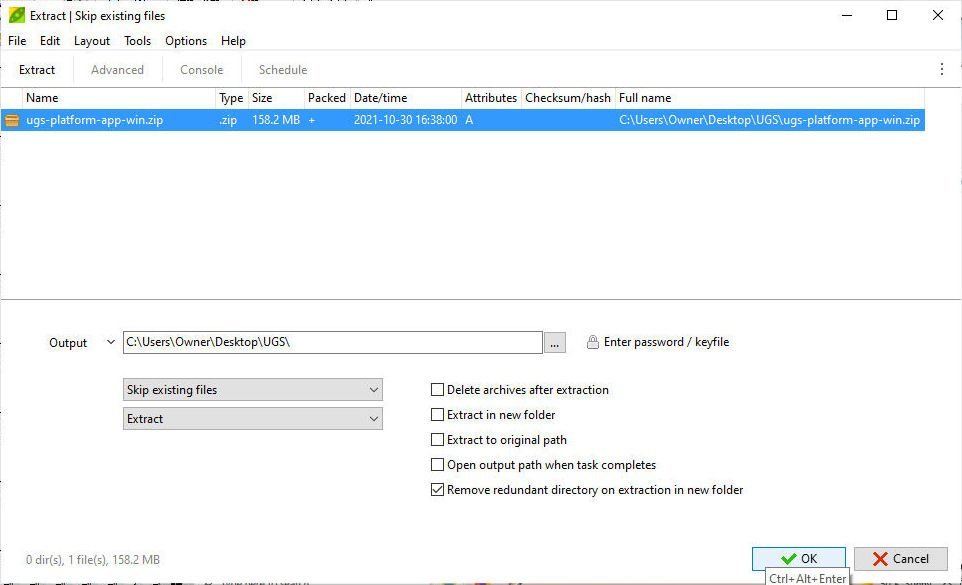
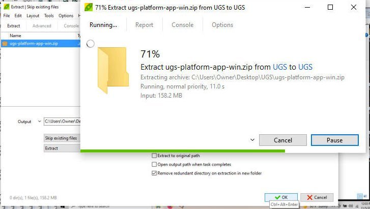
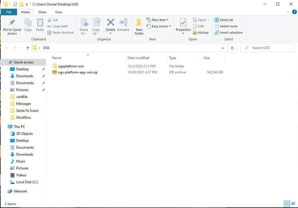
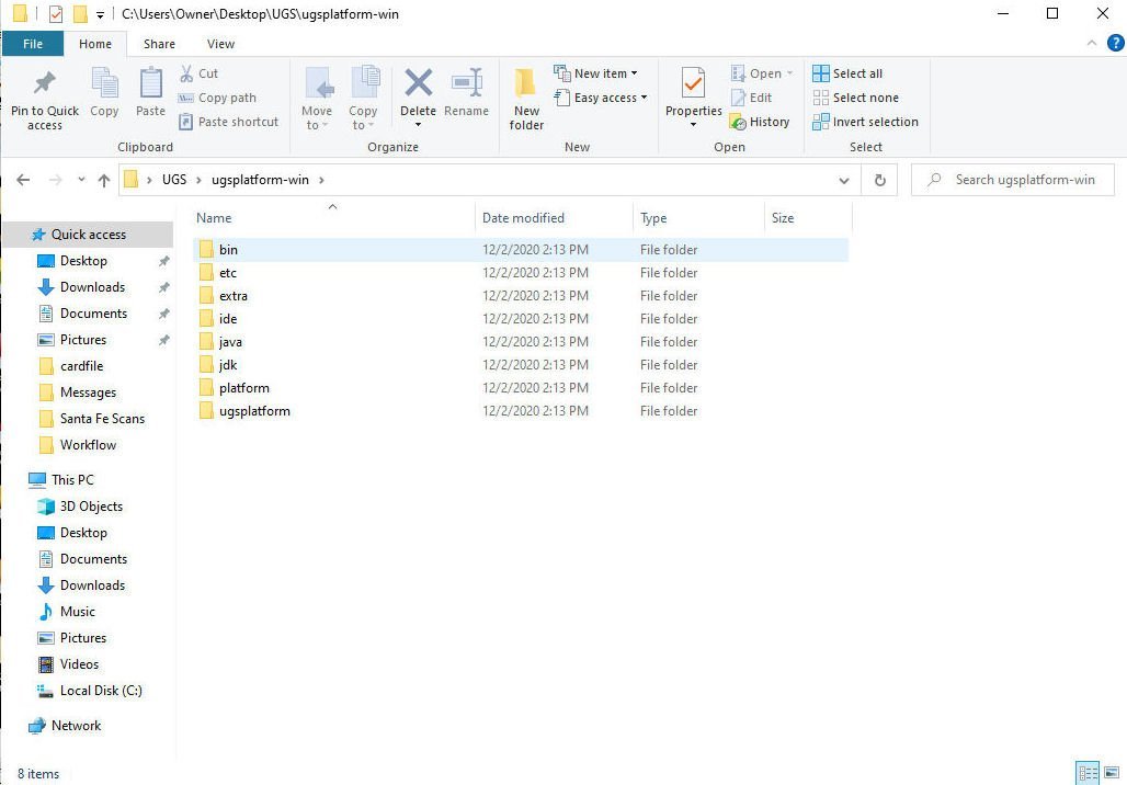
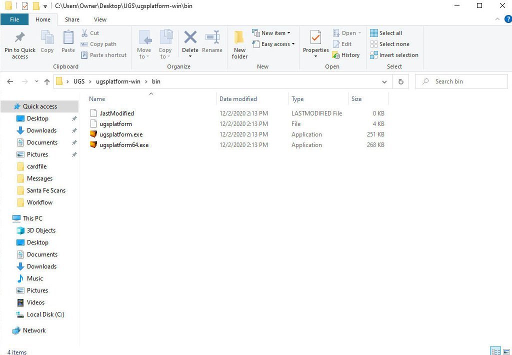
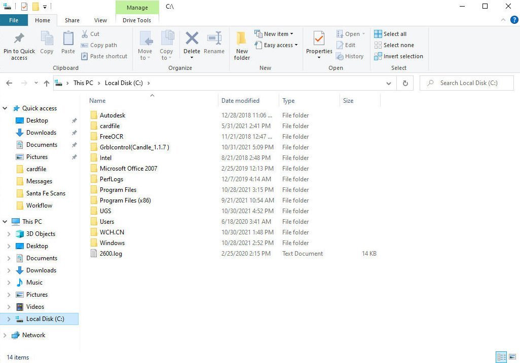
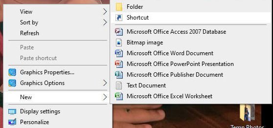
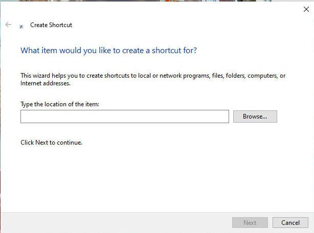
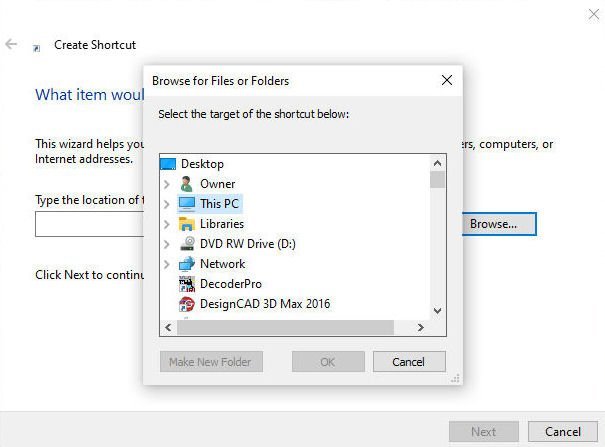
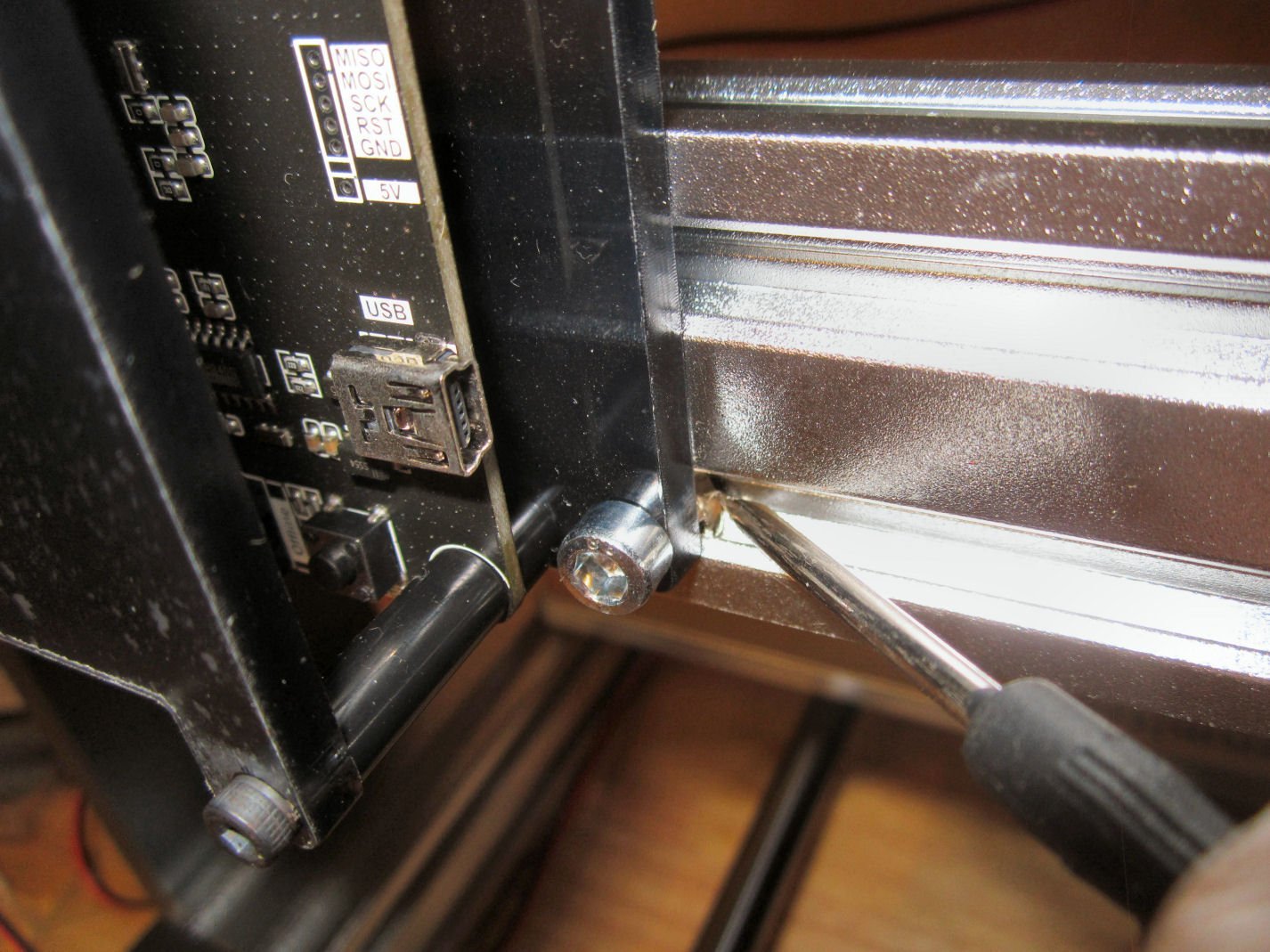
Part 009 Installation of Universal G-Code Sender “UGS” Before installing either of the G-Code programs, follow the directions in the start-up manual and install the SainSmart drivers from the USB Thumb drive, and find out which Com Port to use (plug in the machine using the USB cable first). Record it. The next two parts will be a detailed installation of UGS. Some of the steps will be familiar to most Windows Users, but I included them for any who may not have done them before. UGS is a free Open Source software program, that is used to take a G-Code (a type of machine control software) file and send the steps to a CNC machine. The G-Code is created by a Design software program , like Easel, Carbide Create, CarveCo, The Professional Version of Fusion, etc. The free version of Fusion will not generate G-Code. Using a web browser (these screens are from FireFox), search for USG software (searching for just USG will bring up several businesses, and at least one university). Yes, my search was just for USG in the screen shot. For this shot I selected USG - Github. Then I selected “Download”. Then I selected “Windows” Then “Save File” and “OK” While the file was downloading, to monitor the progress, in my browser, I selected “Tools” and then “Downloads”. When the download was finished I opened the Downloads Folder in my User directory. The file is shown circled below. The site’s directions say to extract the compressed .ZIP file from here. I use PeaZip, and I don’t know where the un-Zipped files ended up, but I couldn’t find them! So I created a folder labeled “UGS” on my Desktop and copied the file there. Opening the folder I Right Clicked on it and selected PeaZip, then “Extract”. PeaZip opens this window. I selected “OK” and waited for the process to finish. When it was finished this new directory had been created. Opening the directory you will see this. Open the “bin” folder. Ugsplatform.exe (for a 32bit system), or ugsplatform64.exe are the programs that run UGS. You can either go through this and click on the appropriate file, to start the program each time, or create a shortcut icon on your desktop to run the program from. To declutter my Desktop I copied the UGS directory to the 😄 drive, and then deleted it from the Desktop. To create the Icon, Right Click on the Desktop and select “New” and then “Shortcut”. This window will open. Select “Browse”, and this window will open. Select “This PC”, then “Local Disk C” and then select the “UGS” directory, then the “bin” directory. Continued in Part 10.

-
Yes, UGS is free. Search UGS software or UGS download.
-
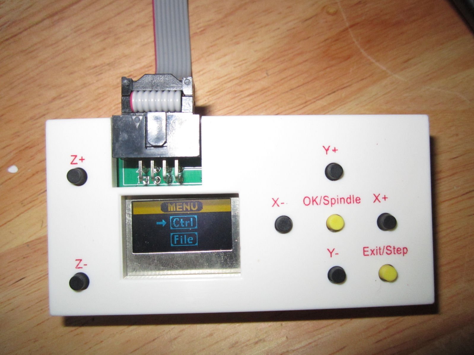
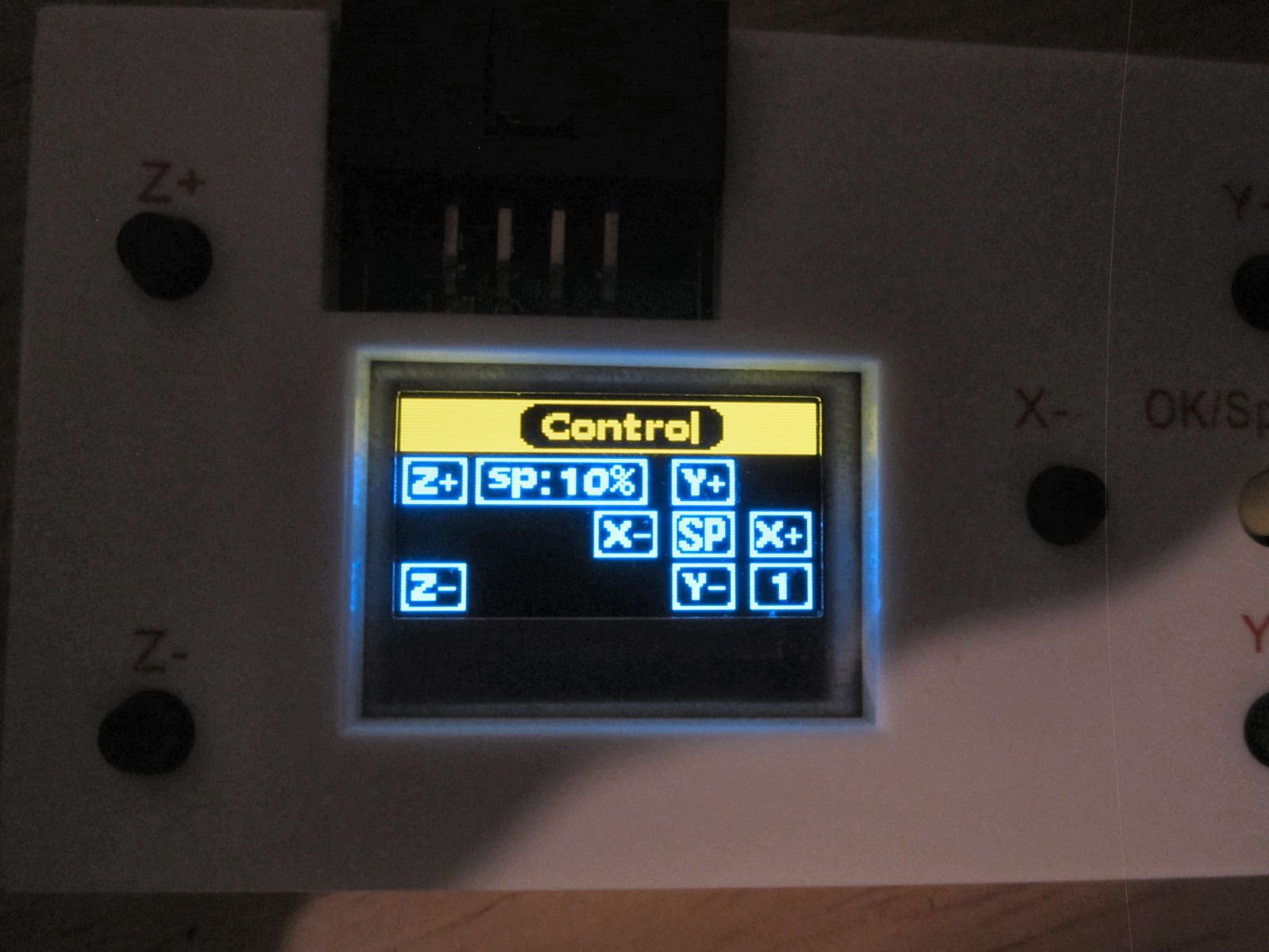
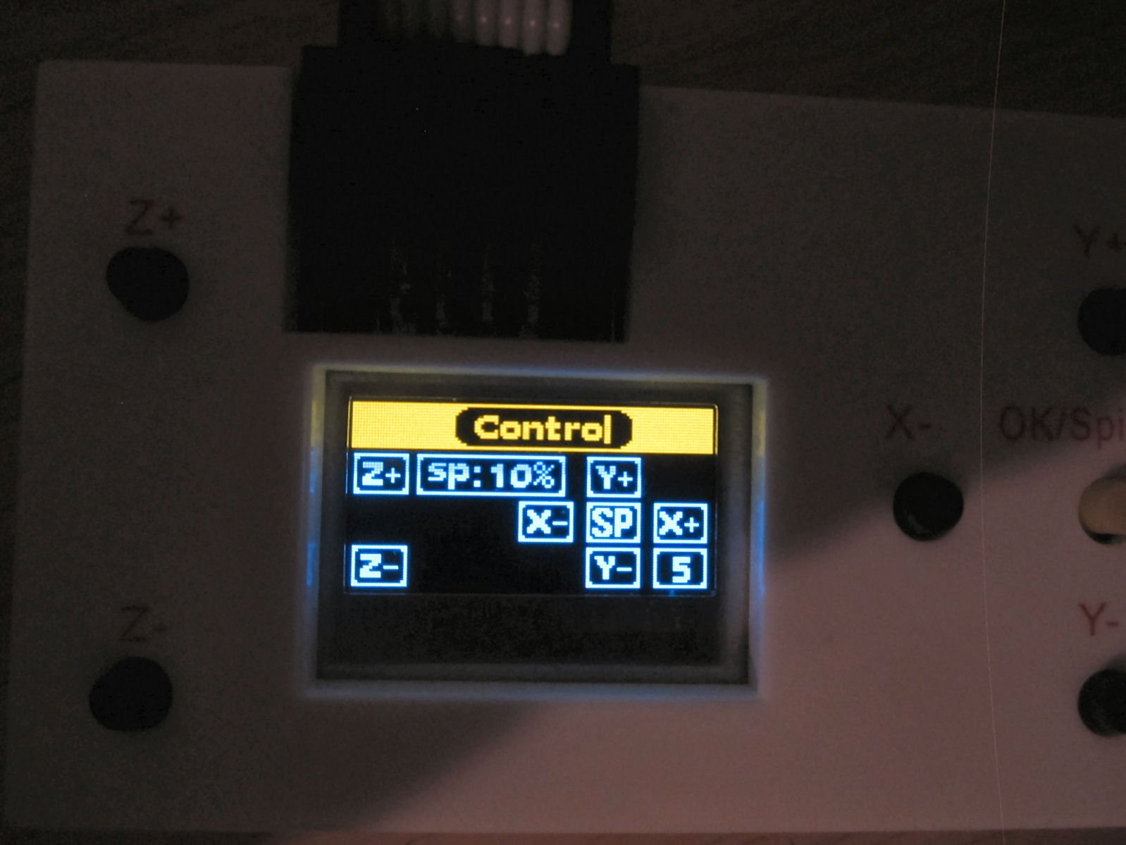
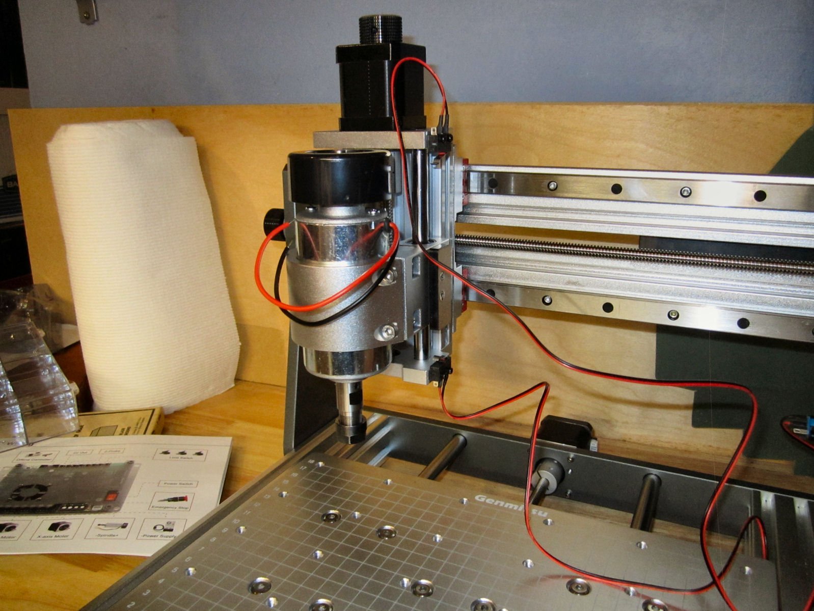
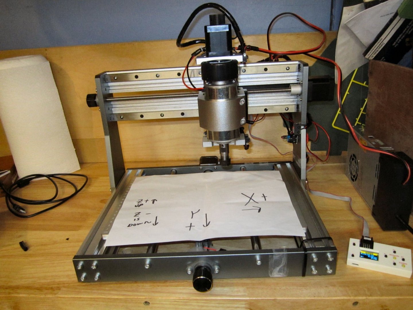
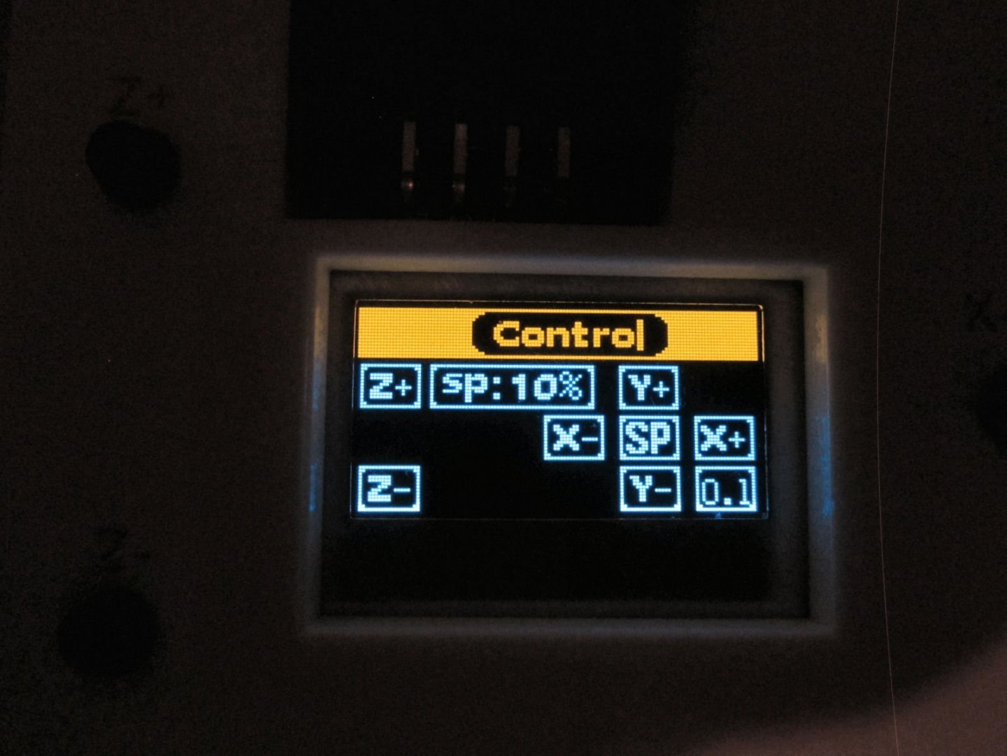
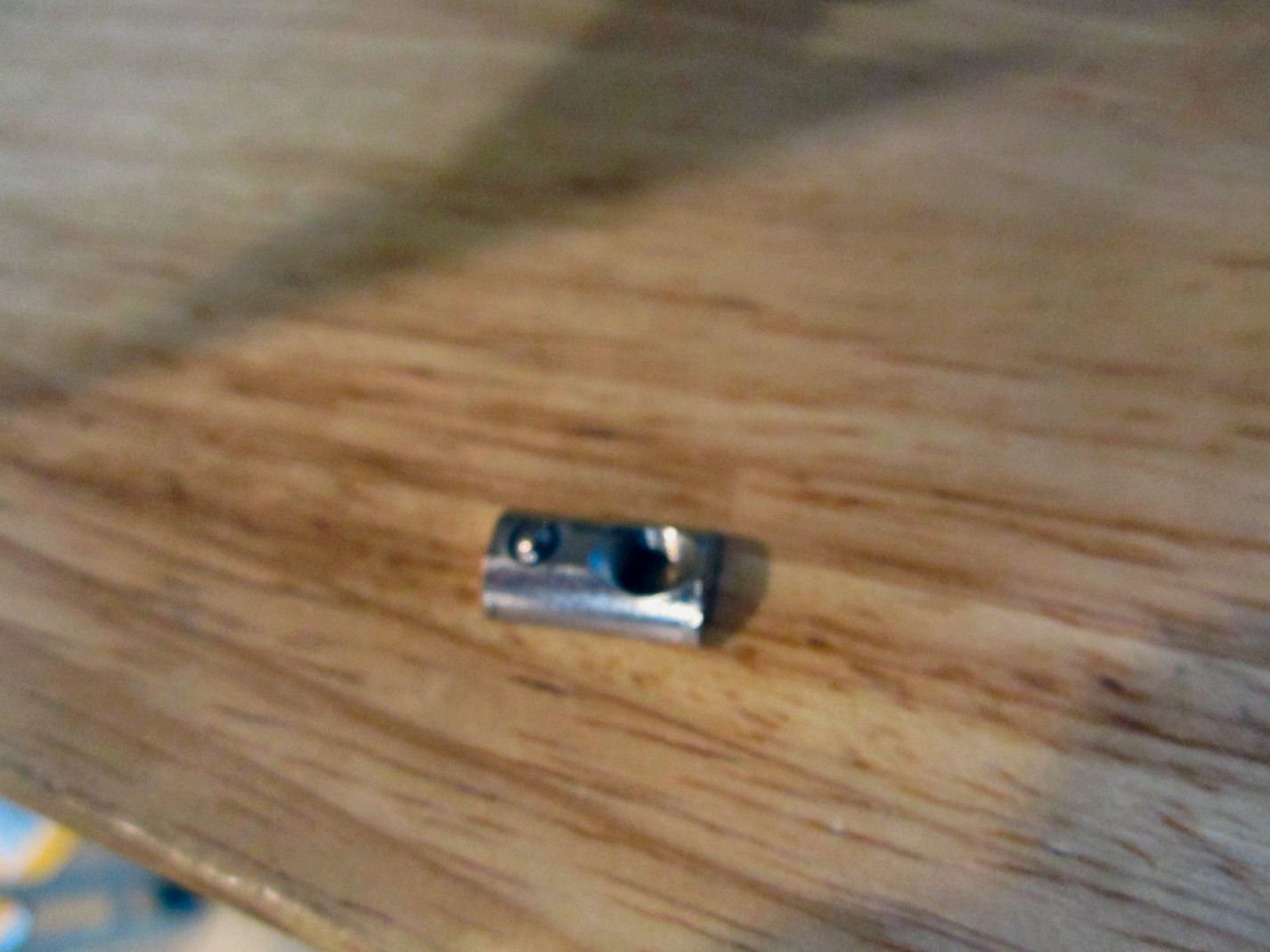
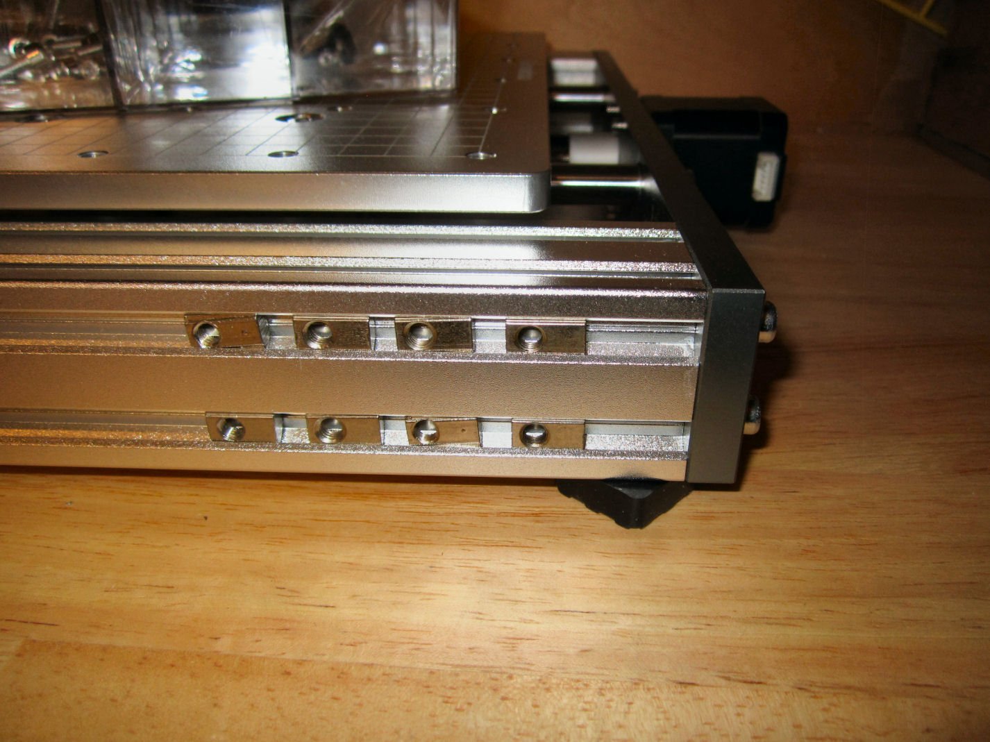
Part 008 With everything ready, I plugged the Standalone Control Box to the router controller and ran all the axis back and forth. The picture shows a piece of paper on the router table showing the directions the + travel commands run the spindle and table. When homed to 0,0,0 the spindle is positioned all the way to the right, the table is all the way forward, and the spindle is all the way up. This positions the spindle at the far right, and at the back of the table. So any commands to move are all –X, -Y, and –Z from the home position. One thing to note, if the system is run (except during the “Home” operation) to the point that one of the limit switches is activated the system stops and no further commands are accepted, even those to move away from that position. You have to manually move that axis away from the switch, using the knobs. You can use the knobs with the system on, no damage will occur from back driving the servos by hand. Moving the servo shaft by hand causes it to act like a generator, and some devices can be damaged if not correctly protected, this system is protected. Don’t, however, grab one of the knobs when the table or spindle are moving! The manual says to have either the Offline Controller plugged in, or the USB cable plugged into the router Controller box, but not both at the same time! With the Offline Controller hooked up, this screen comes up when the powered is turned on. Push the “OK/Spindle” button, and you will be taken to the manual control screen. Pushing the “Exit/Step” button will change the distance the axis will move when one of the axis +/- buttons are pressed (lower right value). The default that first comes up is 0.1mm, then it rotates through 1mm, 5mm, and 10mm, then back to 0.1mm. The value in the “sp:” box it the percentage of full speed the spindle rotation is set to. The default is 10%. You can also step the spindle speed up from the default 10%, up to 100%, from the control box, but I forget the combination of buttons needed. After testing the router with the offline controller, I unplugged it and plugged in the USB cable between it and the computer. I then installed the G-Code software provided by SainSmart that drives the machine. G-Code is the set of instructions created by the design software, that gives the direct instructions to the router control board (i.e. go right 10mm, then down 5mm, and lower the spindle 2mm, etc.). I’ll detail installing the software in a later post, when I can get some screen shots of the process. I really wanted to play with the new toy, and didn’t want to take the time to properly record all the steps. This software also has control “buttons” to run the servos back and forth, as well as manually “Home” the spindle, use the Z-Axis probe etc. I was able to control all the axis from the computer. Once again, activating one of the limit switches (except during “Home”) kills all control of the machine, until the offending axis is manually moved away from the switch. The G-code software provided by SainSmart is alright, but I also installed the “Hobby Standard” “Universal G-Code Sender” program "UGS". It too has a control buttons panel. It has a detailed setup wizard that I have to work my way through, before I can use it though. This wizard provides a lot of customization of things like setting software limits for axis travel (which is needed without the second limit switches on the X and Y axis, and a general good idea, in any case. You can scale commanded travel distance, to what the actual distanced moved was (for example you commanded the spindle to move 200mm, but it actually moved 203mm), etc. Doing this will take a bit of effort, but is why this program is better than the one SainSmart provides. I haven’t loaded the free Easel design program. You can’t just load the Free version of Easel , you have to install the trial version which after 30 days reverts to the free one. So, I wait until I’m ready to actually design something to install this or the CarveCo program. That will come soon, but not right now. I will be trying the sample carving files SainSmart provided, but need to buy some MDF stock to practice on. As a side note, the tapped holes in the table, for attaching the clamps are 6mm threads. I will be mapping the hole spacing, and hopefully designing a program for making a spoil board. A spoil board is basically a sacrificial board mounted to the table, so that any miss cuts, or designs that pierce the work piece will cut into the spoil board rather than the aluminum table surface. This would be easier if the holes were all equally spaced, but my initial measurements indicate that there is some misalignment to them. Today I bought some 6mm cap screws that may be more precise than the supplied flat head clamp screws. When I installed one of the 20 degree bits, there was a fair gap between the tip and the table surface, so a spoil board will not seriously affect the cutting depth of the spindle.


-
Just getting into the software. I plans to use the UGS as the g-code sender, and I have a 1 year subscription the Carveco.
-
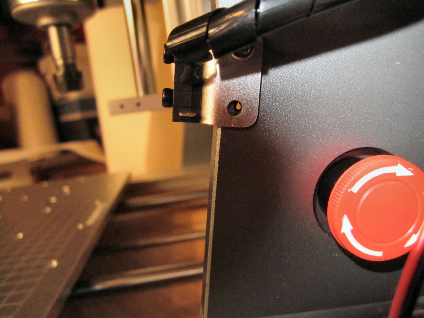
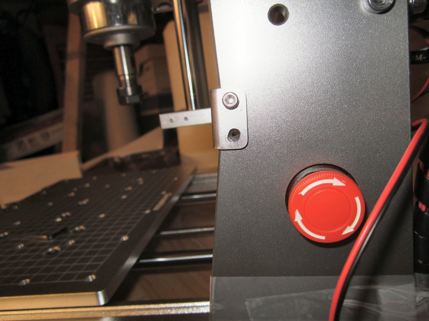
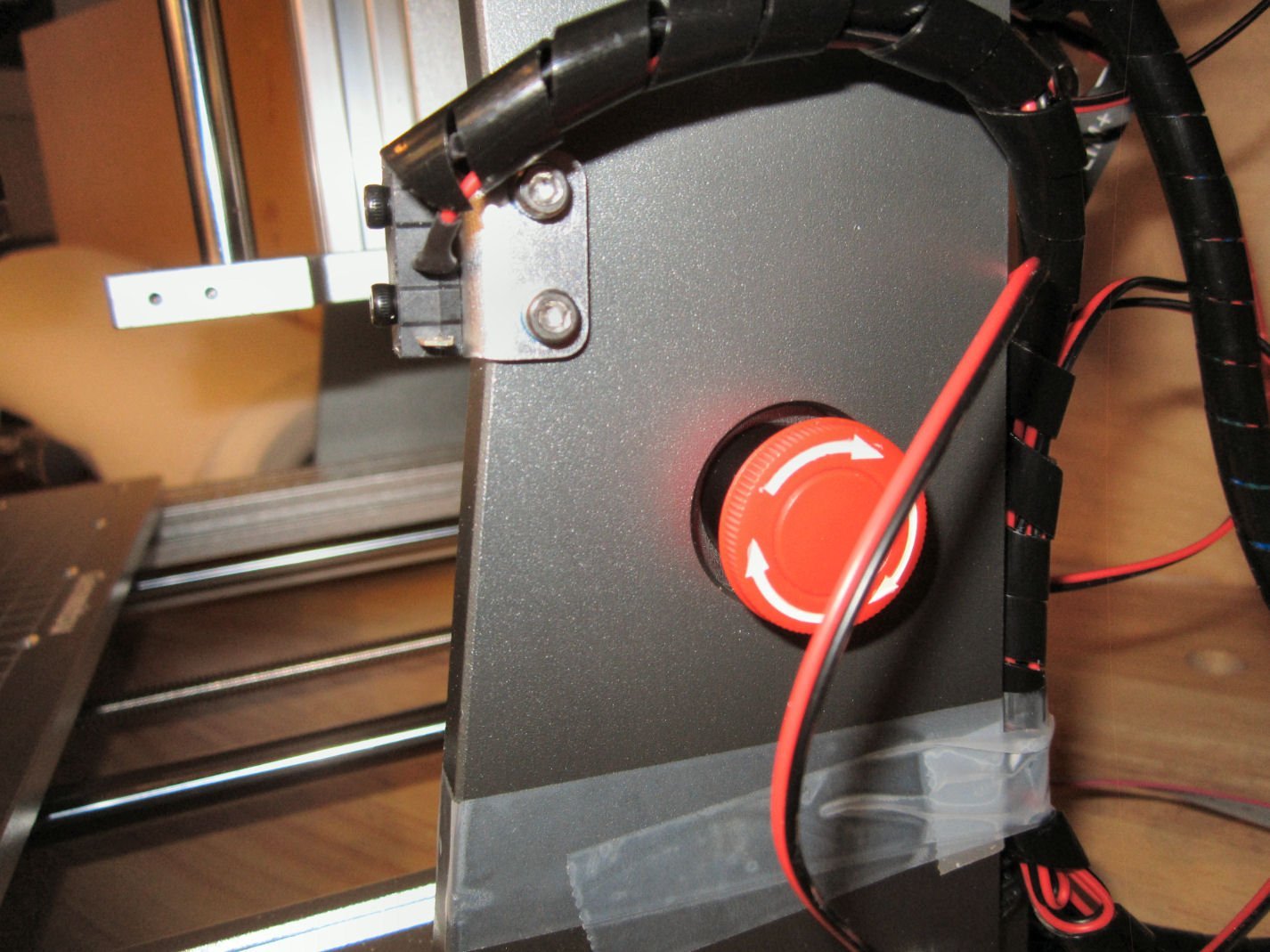
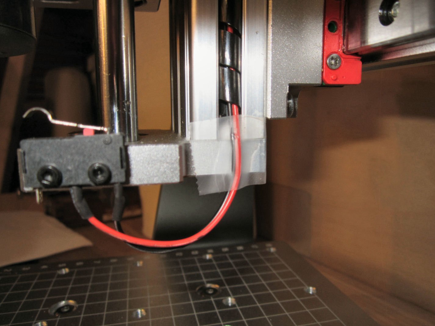
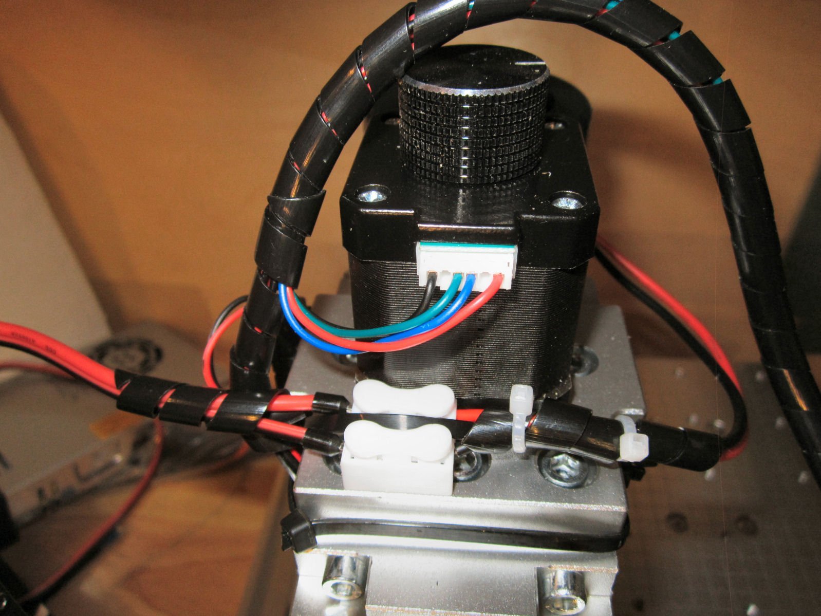
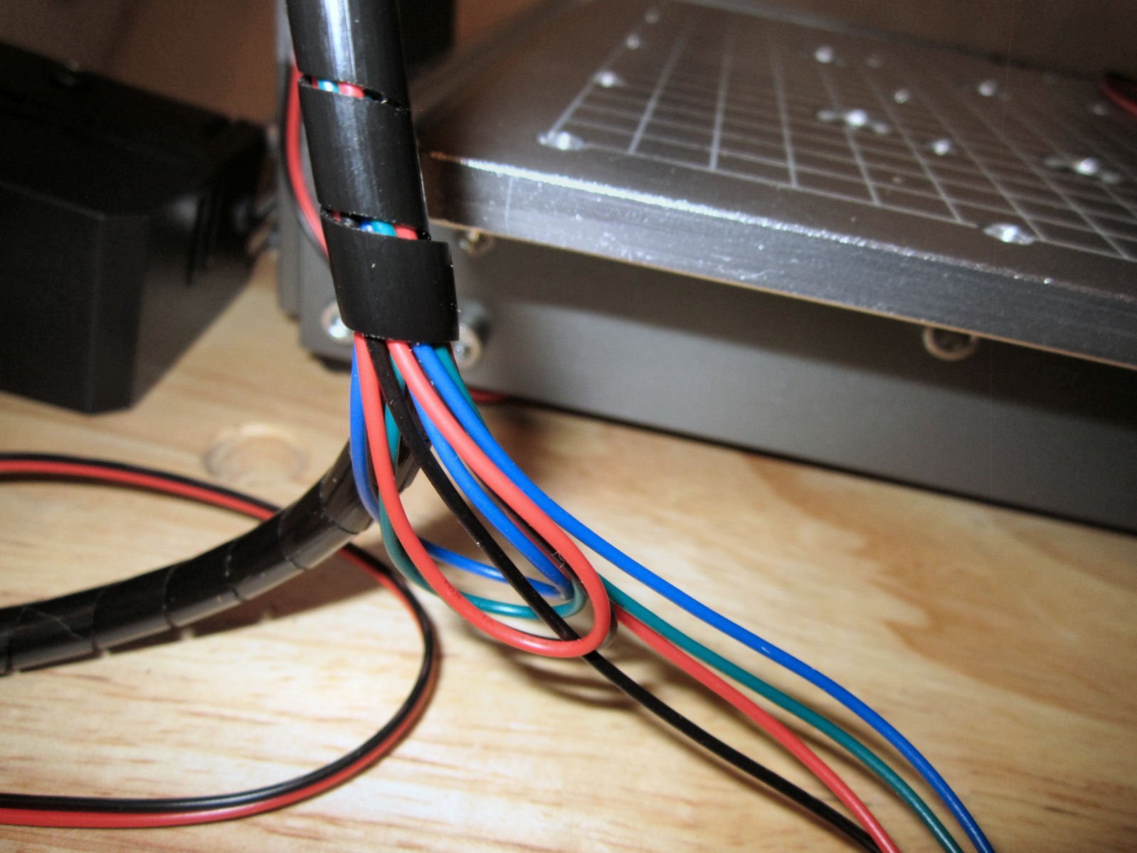
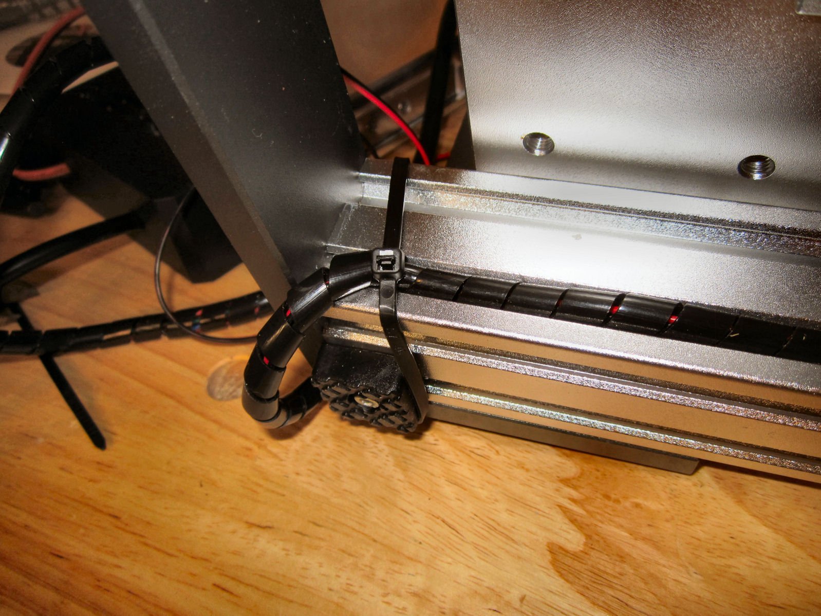
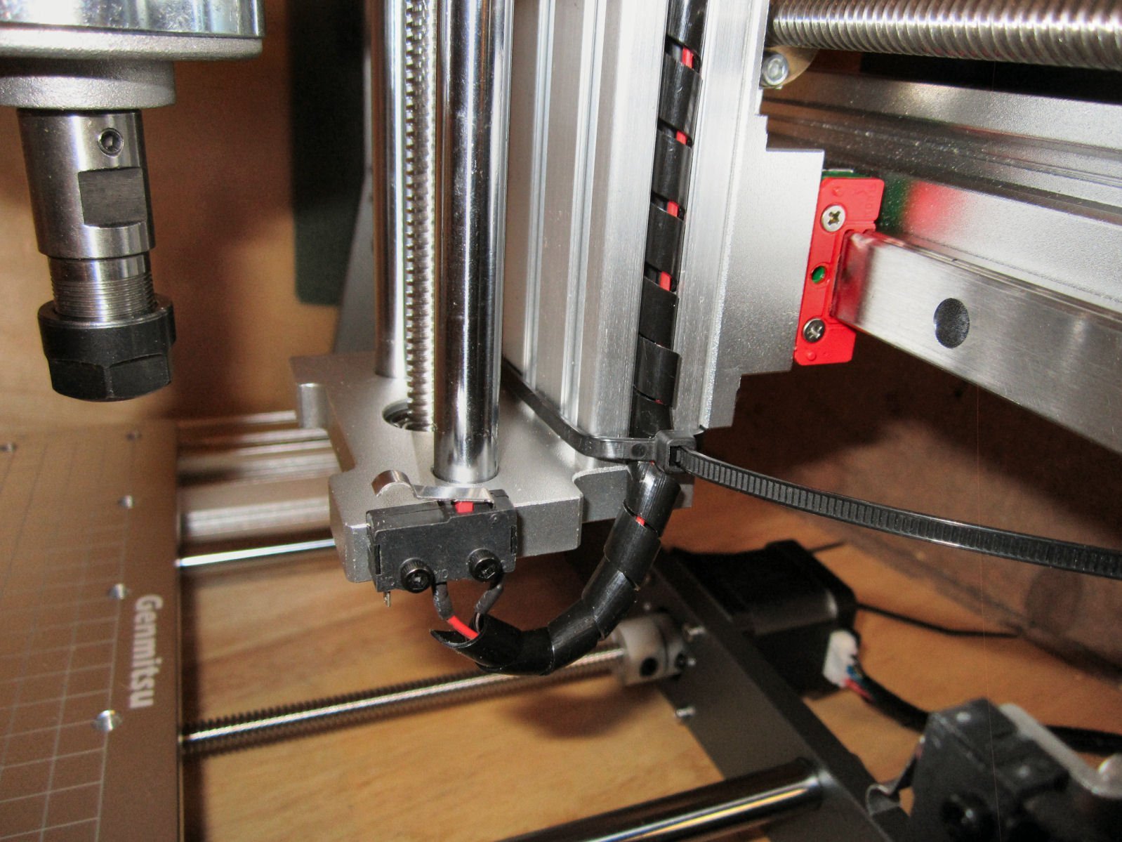
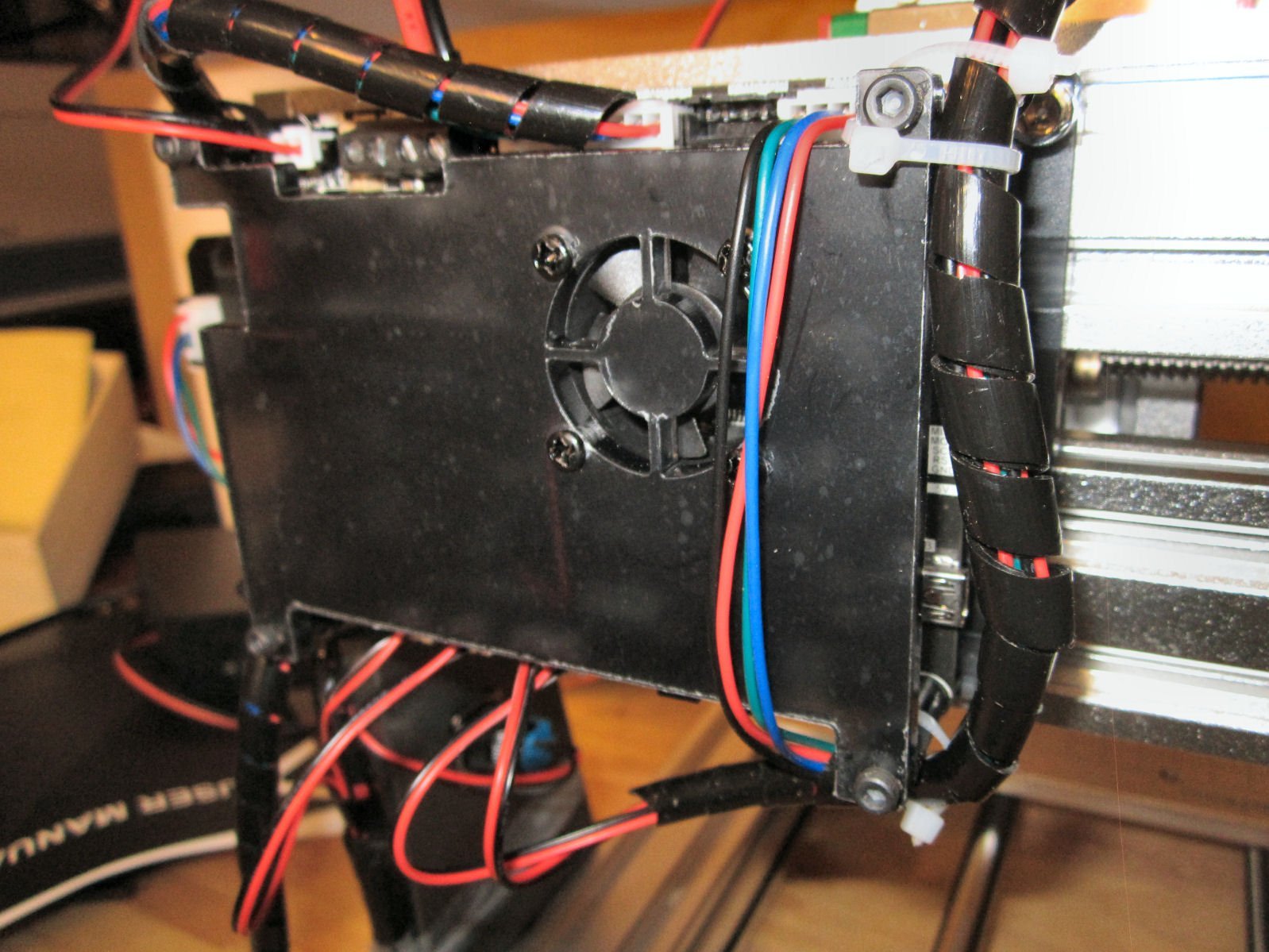
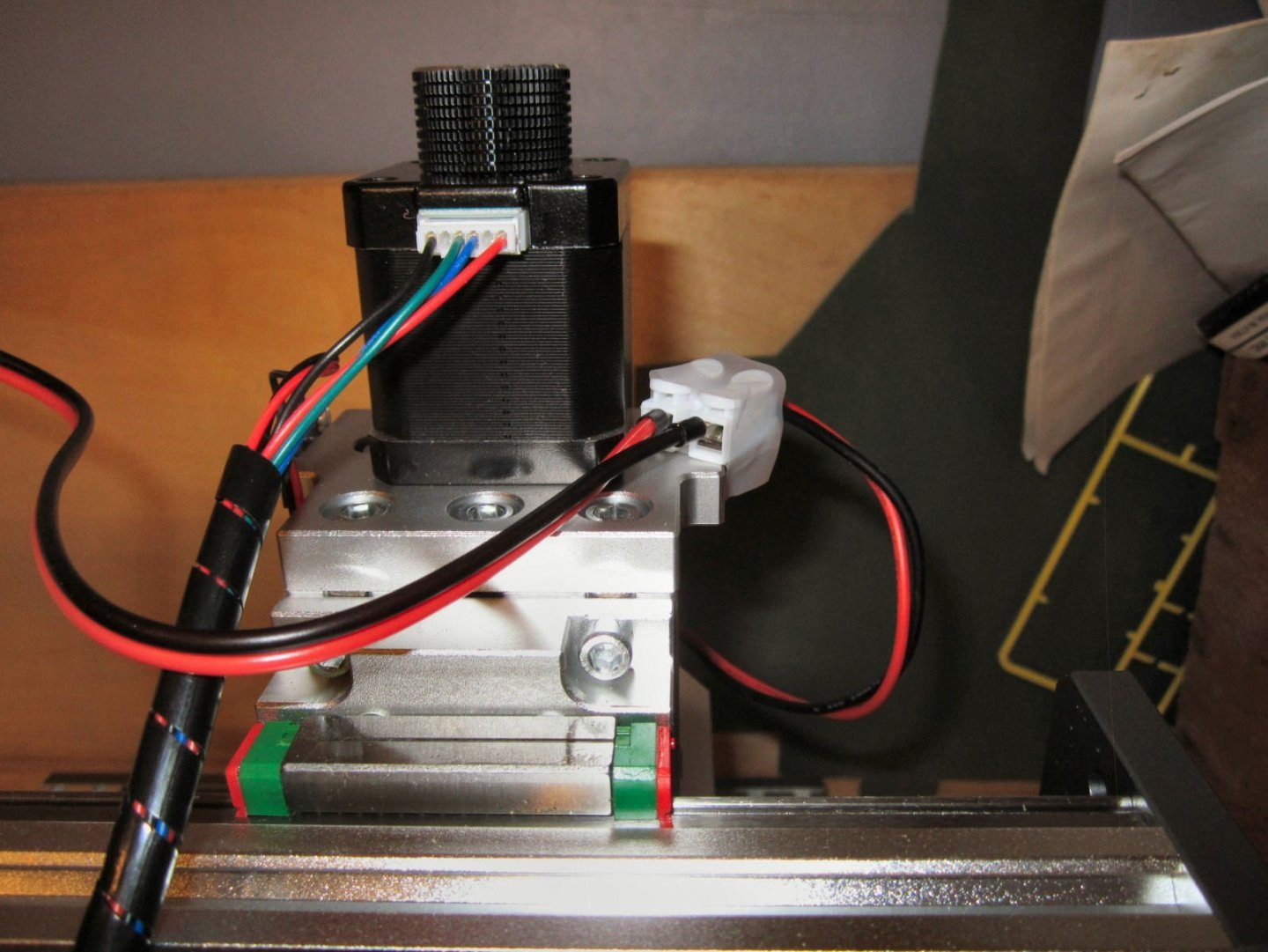
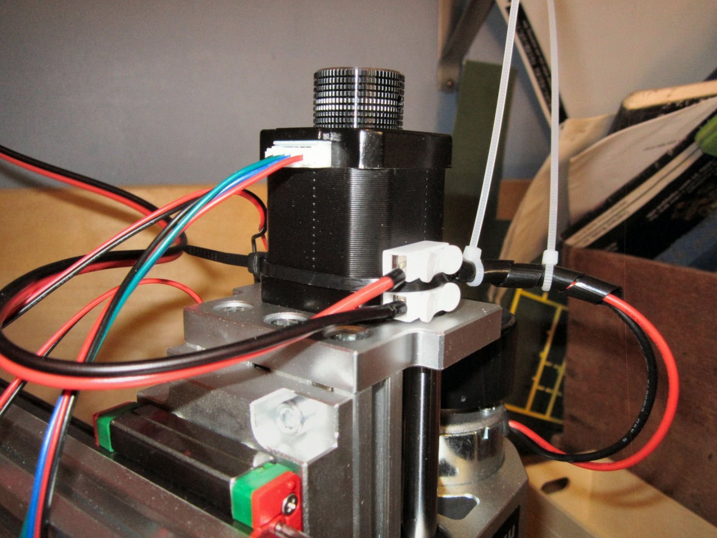
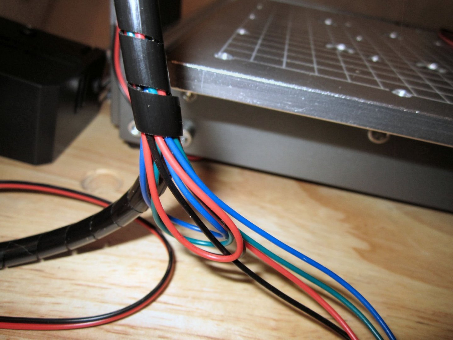
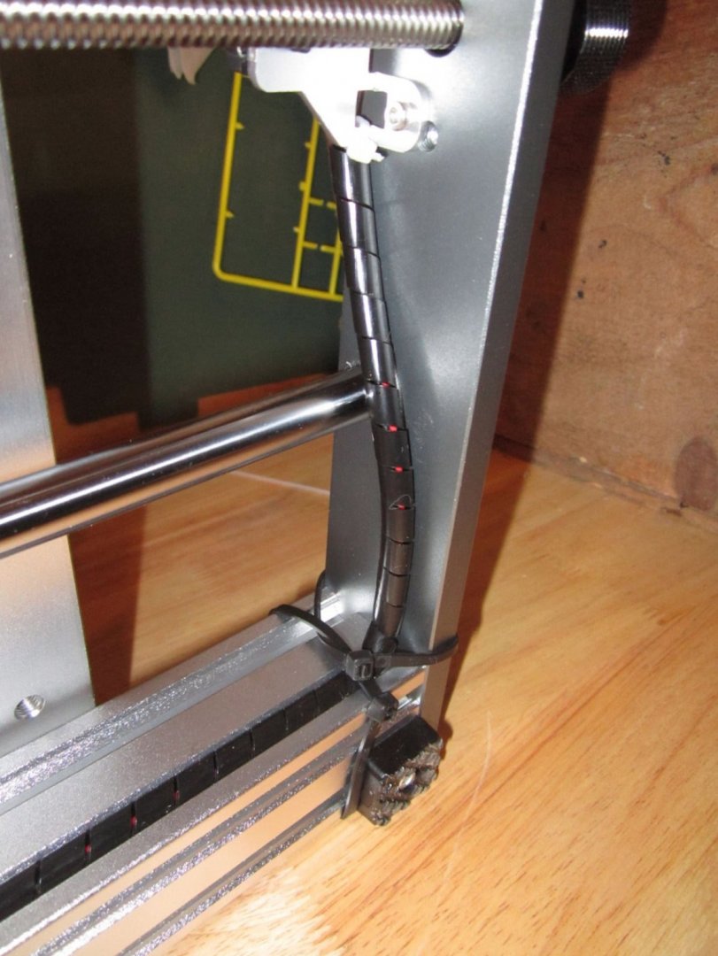
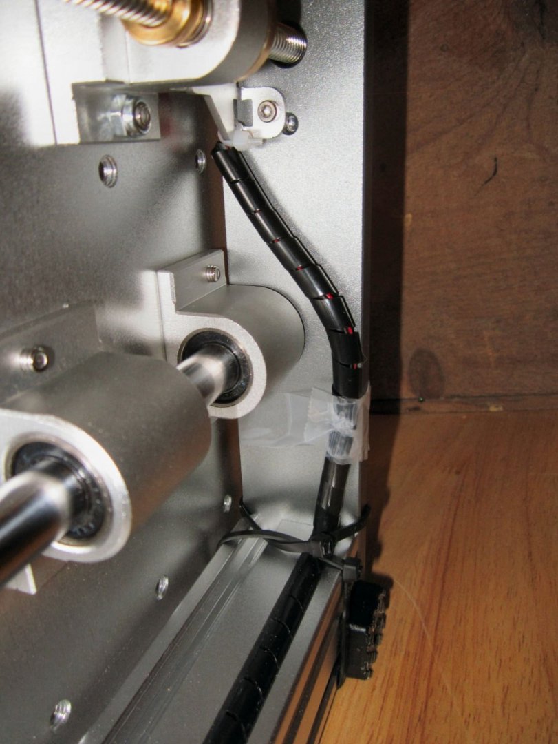
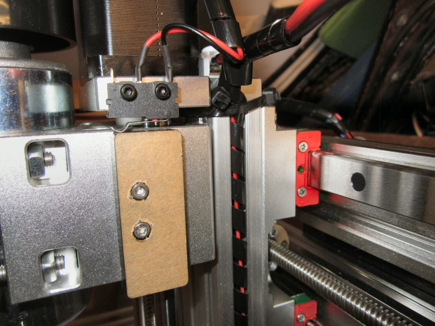
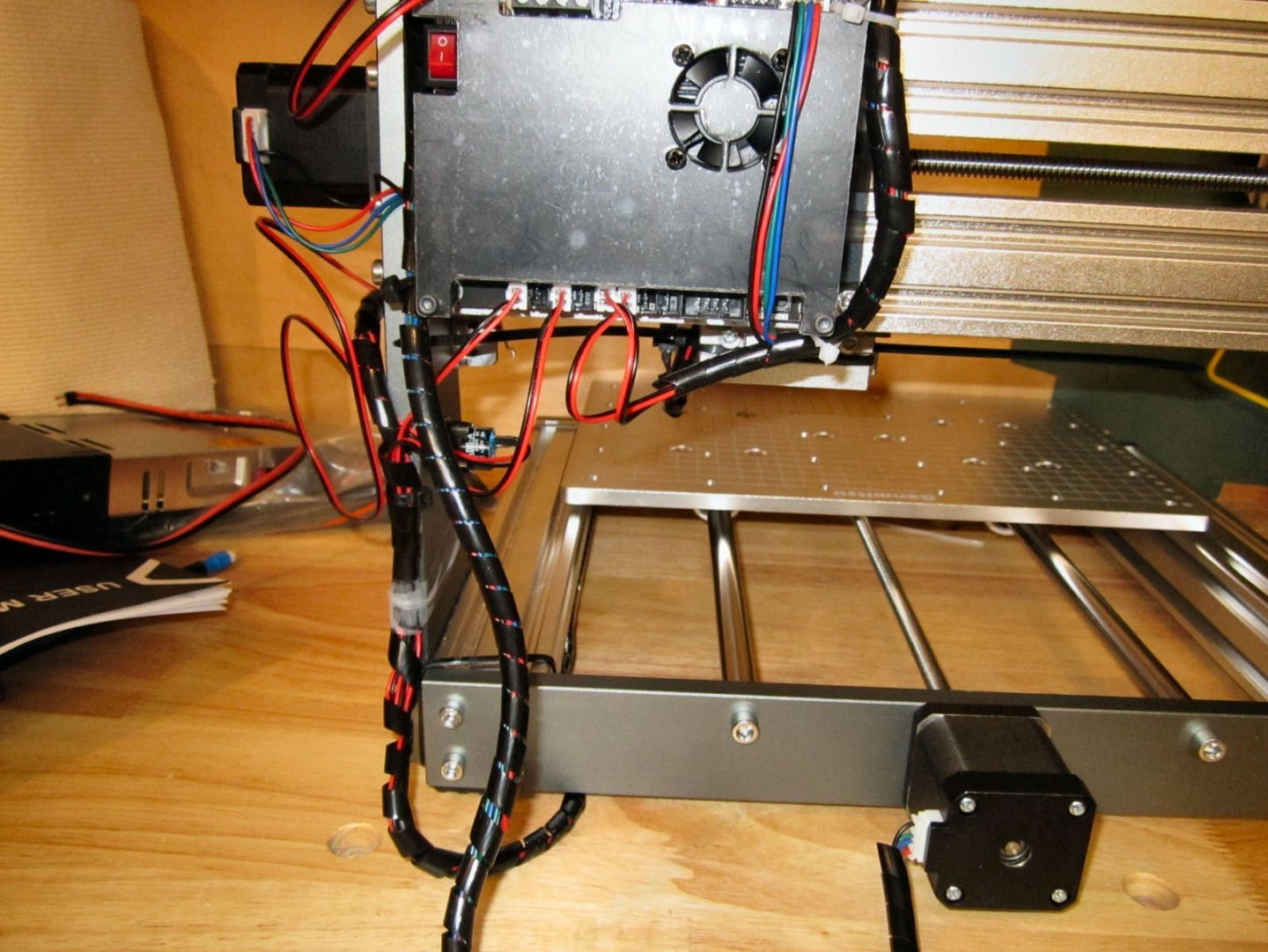
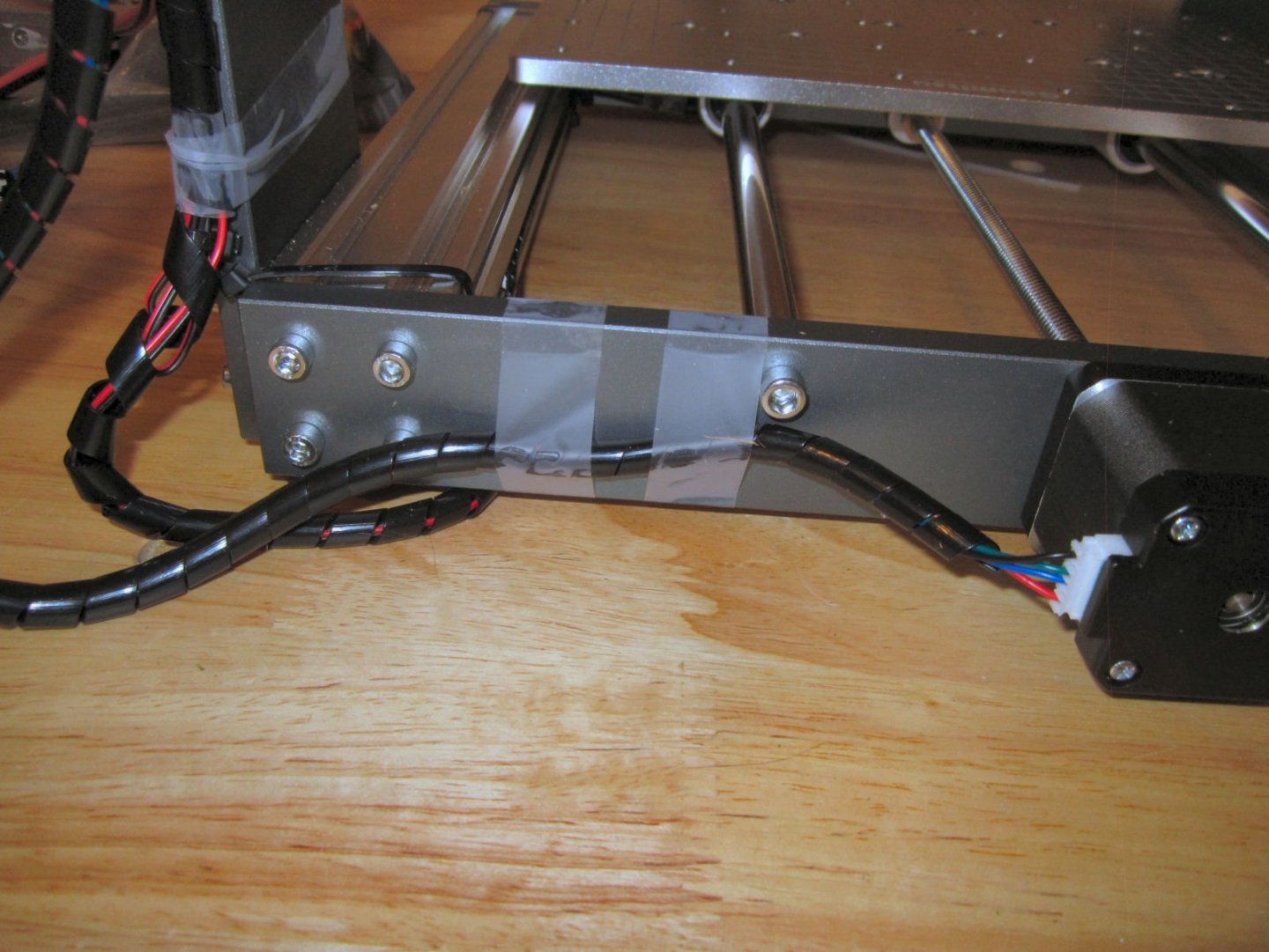
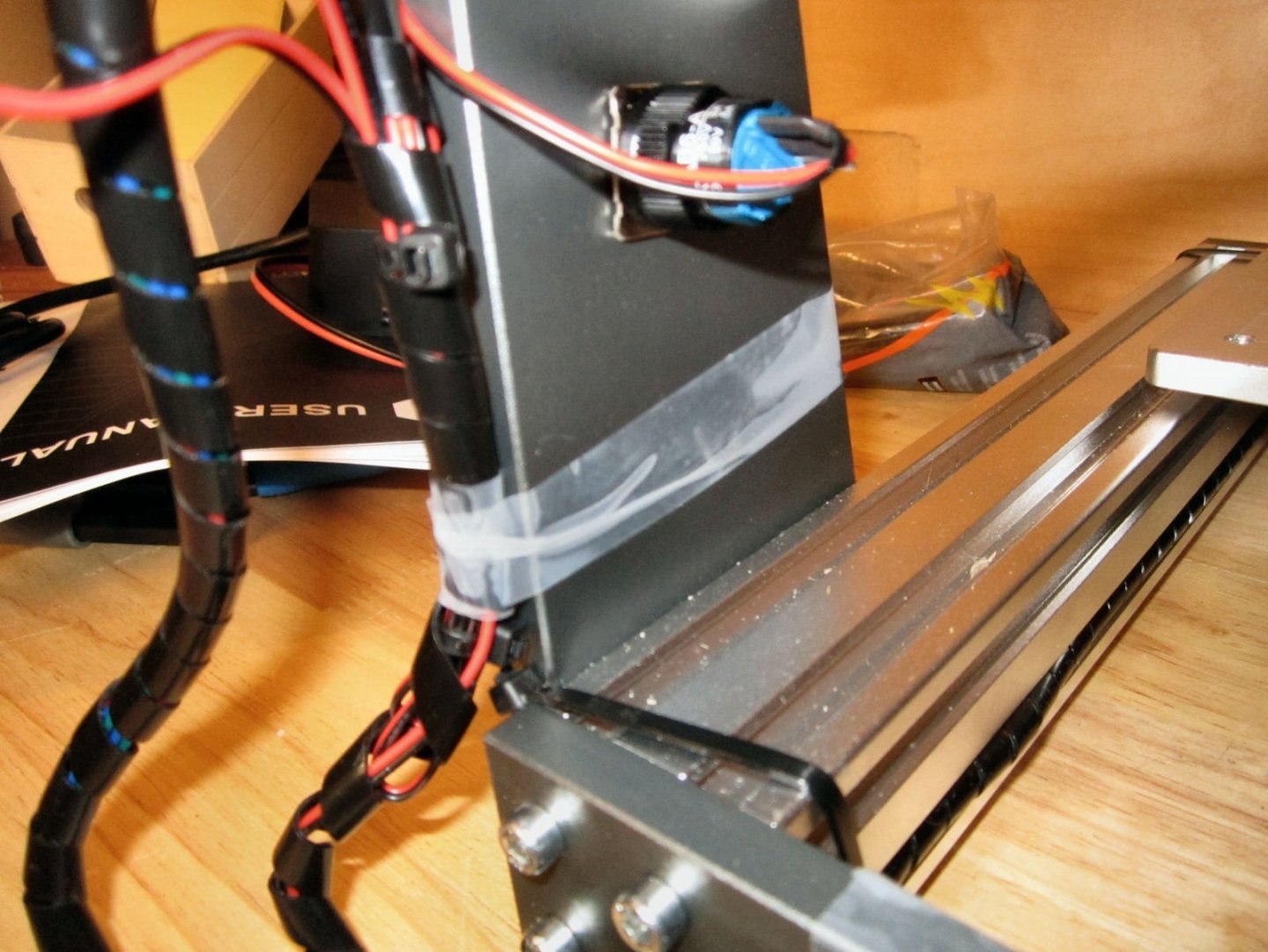
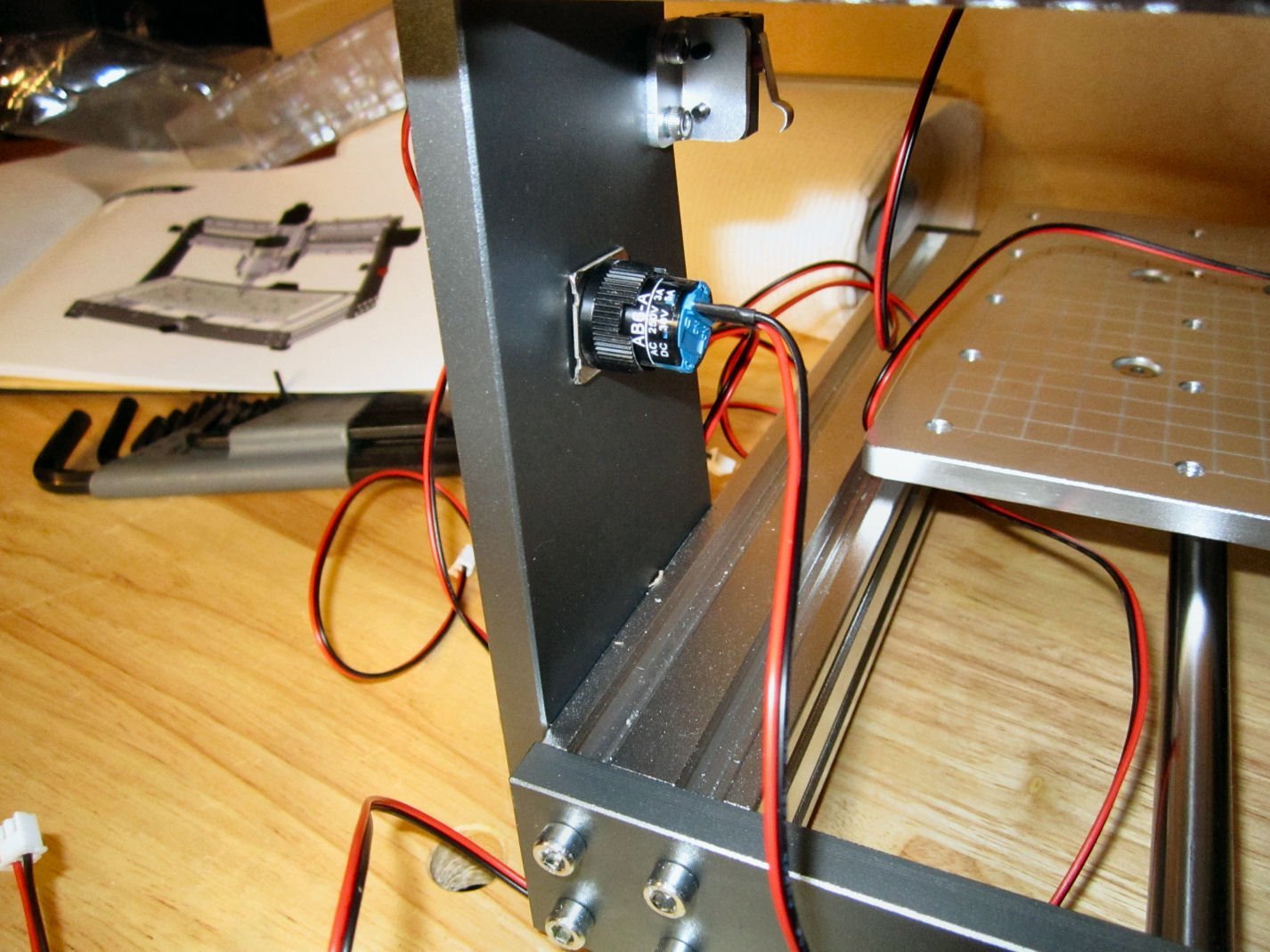
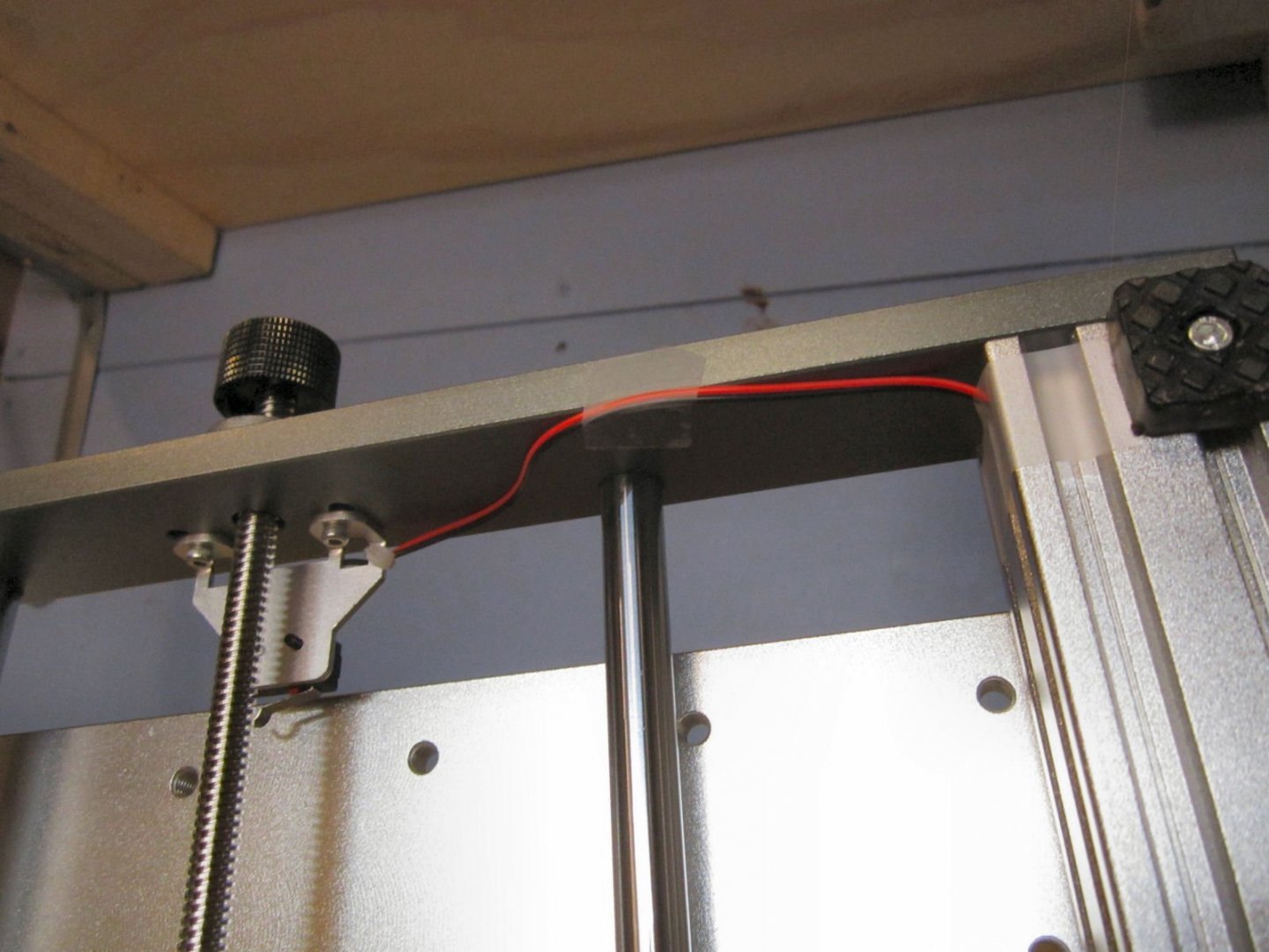
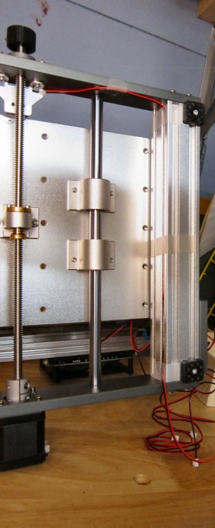
Part 007 I proceeded to wrap the various cables with the supplied spiral wrap. Then I had to figure out how to mount the plastic connector for the spindle motor wires. The first method I tried I really liked, it was neat and simple. Unfortunately, there is very little clearance between the servo motor and the cooling fan on the top of the spindle motor, as I found out when I raised the motor! There was just enough of a bulge in the cable tie to catch the fan as the spindle was raised. So I went with this method. It is not as clean looking, but it works. The upper cable tie holds the spindle motor connector in place, and the horizontal one holds the Z-Axis and servo motor cable in place on the other side of the assembly. Where I had extra lengths of wire, I looped up the excess and ran it along the rest of the wire. Then I wrapped the spiral cable wrap around the whole thing. For the Y-Axis limit switch wire, I discovered that the spiral cable wrap fits into the slots in the extruded side channels, with a secure fit! I secured each end of the length in the channel with cable ties, to prevent the stress at the corner bends from pulling it out. I temporarily used tape to hold the loop of the switch cable down away from the linear slide bearing path. Later I will find some sort of commercial cable hold down for it. Here is a picture of the cable tie supporting the limit switch and servo motor cable. This bundle is pointed up vertically, so that there is a loop of wire suspended over the machine, to make sure the cables do not rub as the spindle assembly goes back and forth along the X-Axis. This is the other end of that bundle (right hand side). The spindle motor wires go out horizontally to the left, above the level of the top of the supports, loops up and over, then comes back down vertically into the screw connectors at the top of the controller board. This shows the cable bundle (left in picture) for the Y-Axis Limit Switch, and the wires from the X-Axis switch and servo motor. This bundle is also held in place with tape for now. The cable you see running all over the place on the left, is for the E-Stop Switch. I did not bundle it with the other cables, as I will be moving it to the enclose I will be building next week. It taped it out of the way for now. I taped the Y-Axis servo motor bundle out of the way. A closer shot of the tape holding the cable bundle. I wrapped it all the way around the upright, as there was a bit of stress to hold it there, The following pictures show the cable bundle for the Y-Axis limit switch, The X-Axis limit switch, the X-Axis servo wires, and the Y-Axis servo wires. I cable tied them to the mounting screws for the controller, with enough of a loop at the top to keep the servo wires off of the controller box. I later added a short pieces of cable wrap to cover the X-Axis servo wires shown laying against the upright, as well as the ones crossing the back of the controller box.


-
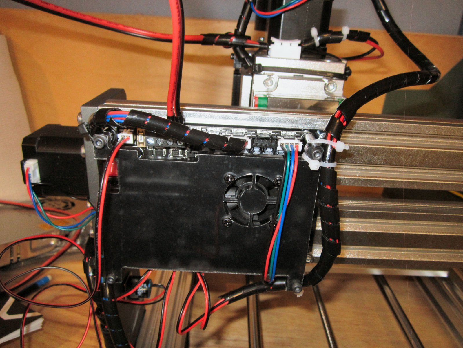
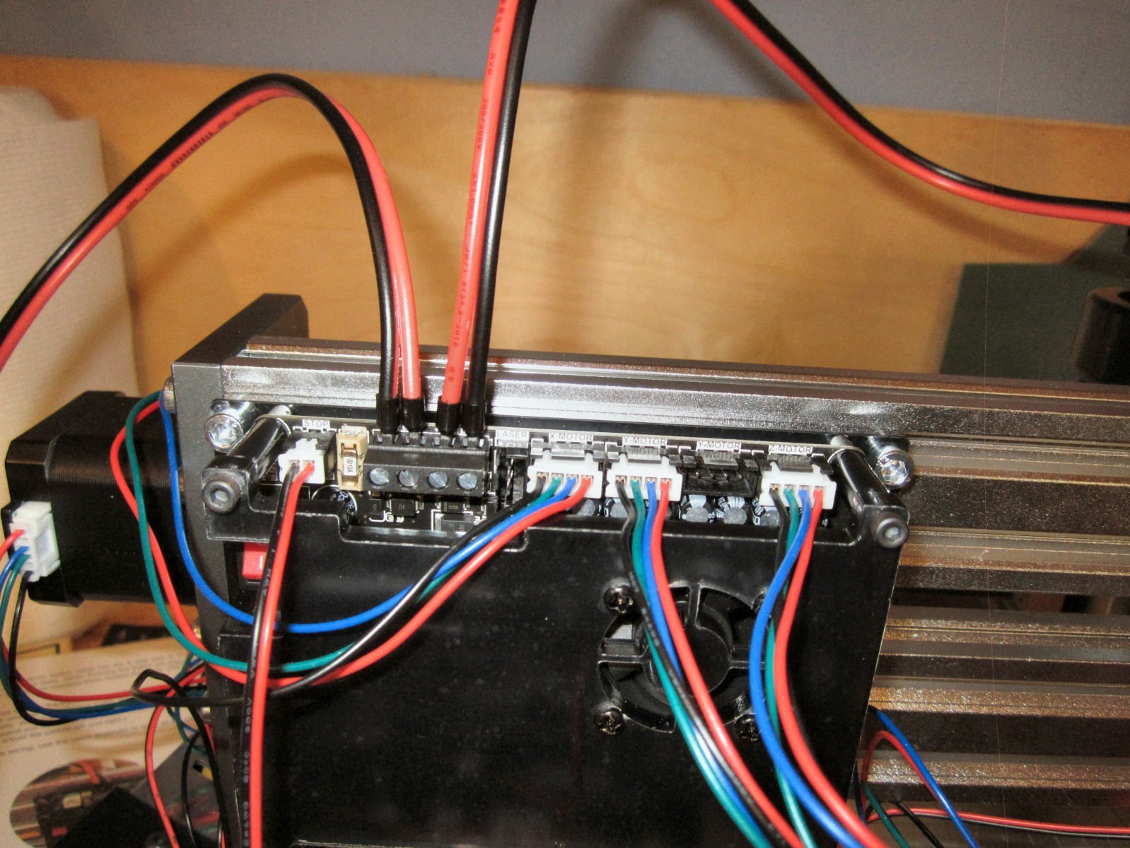
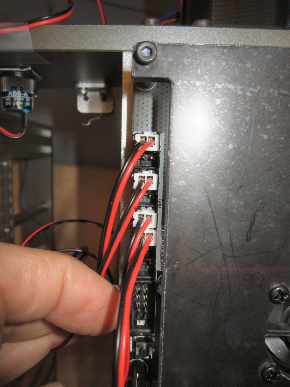
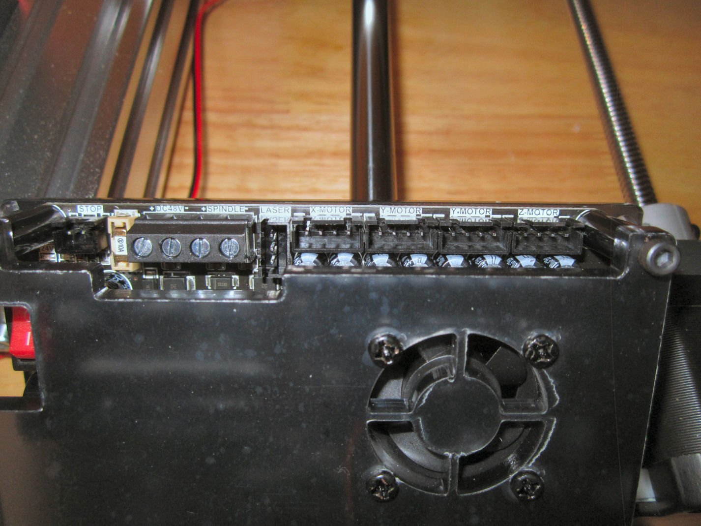
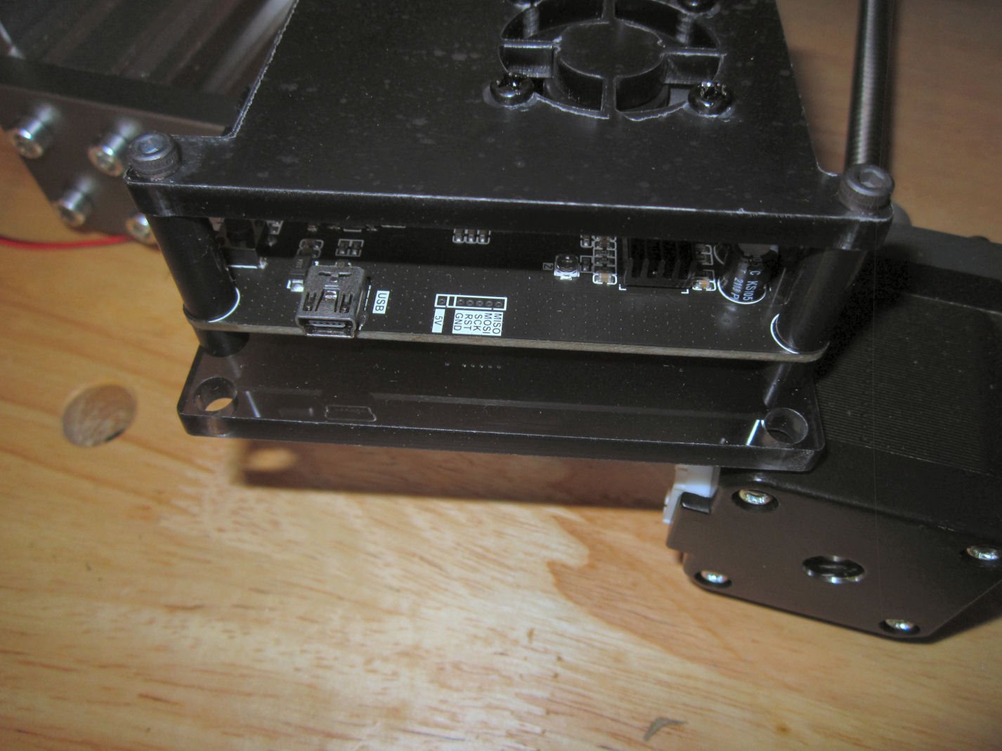
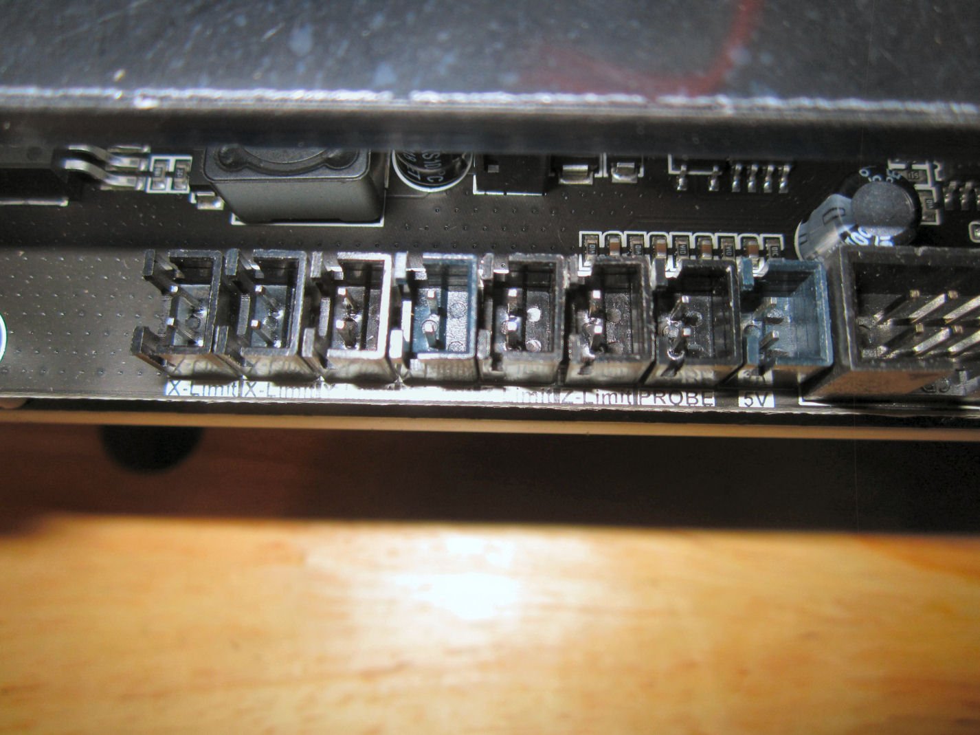
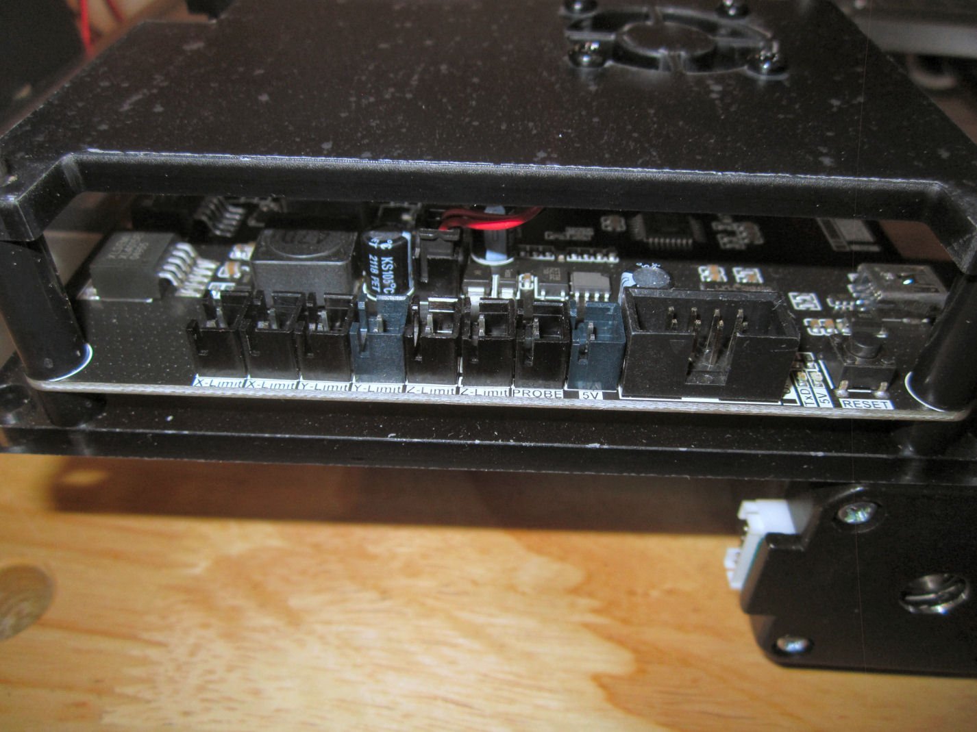
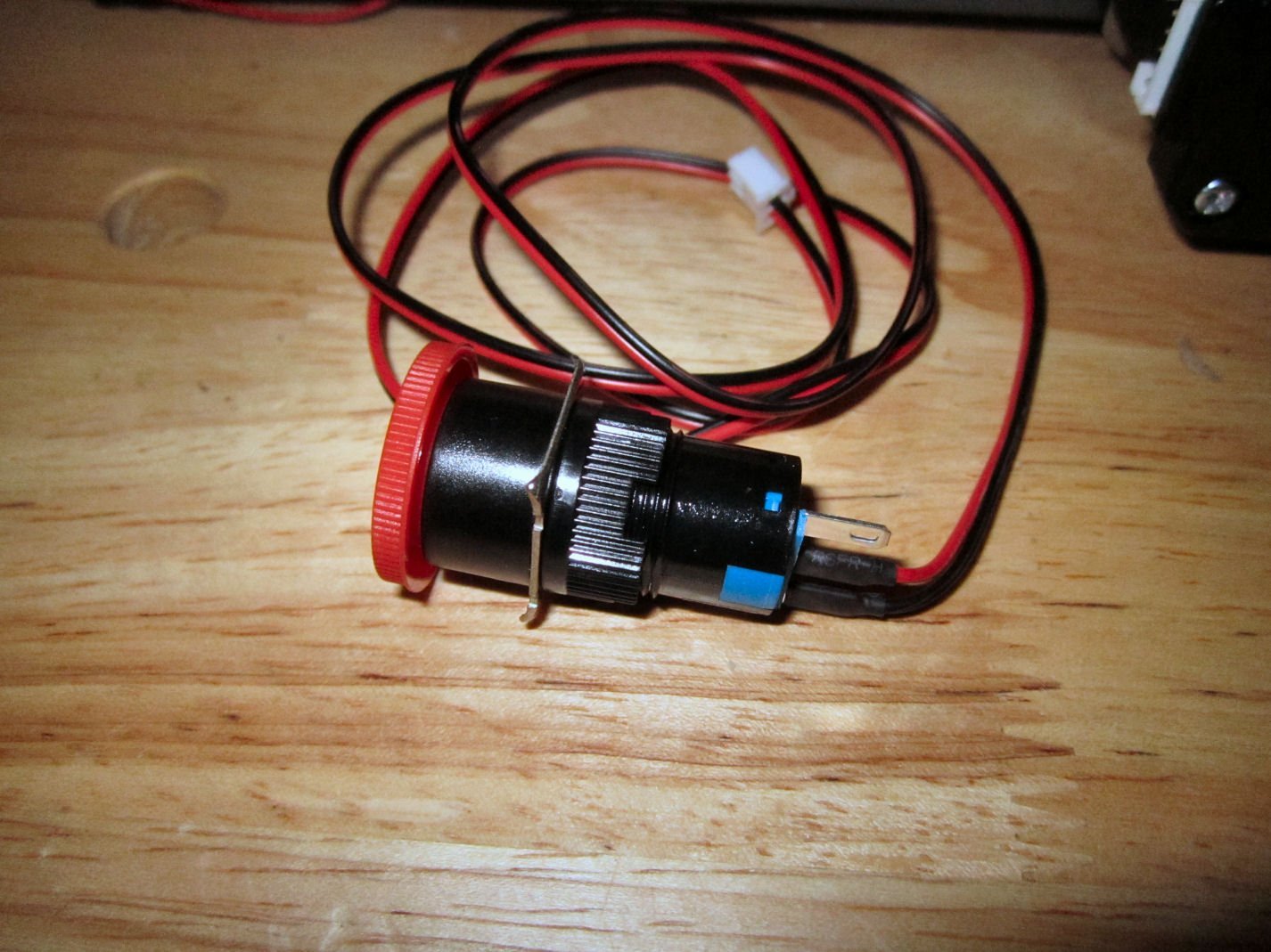
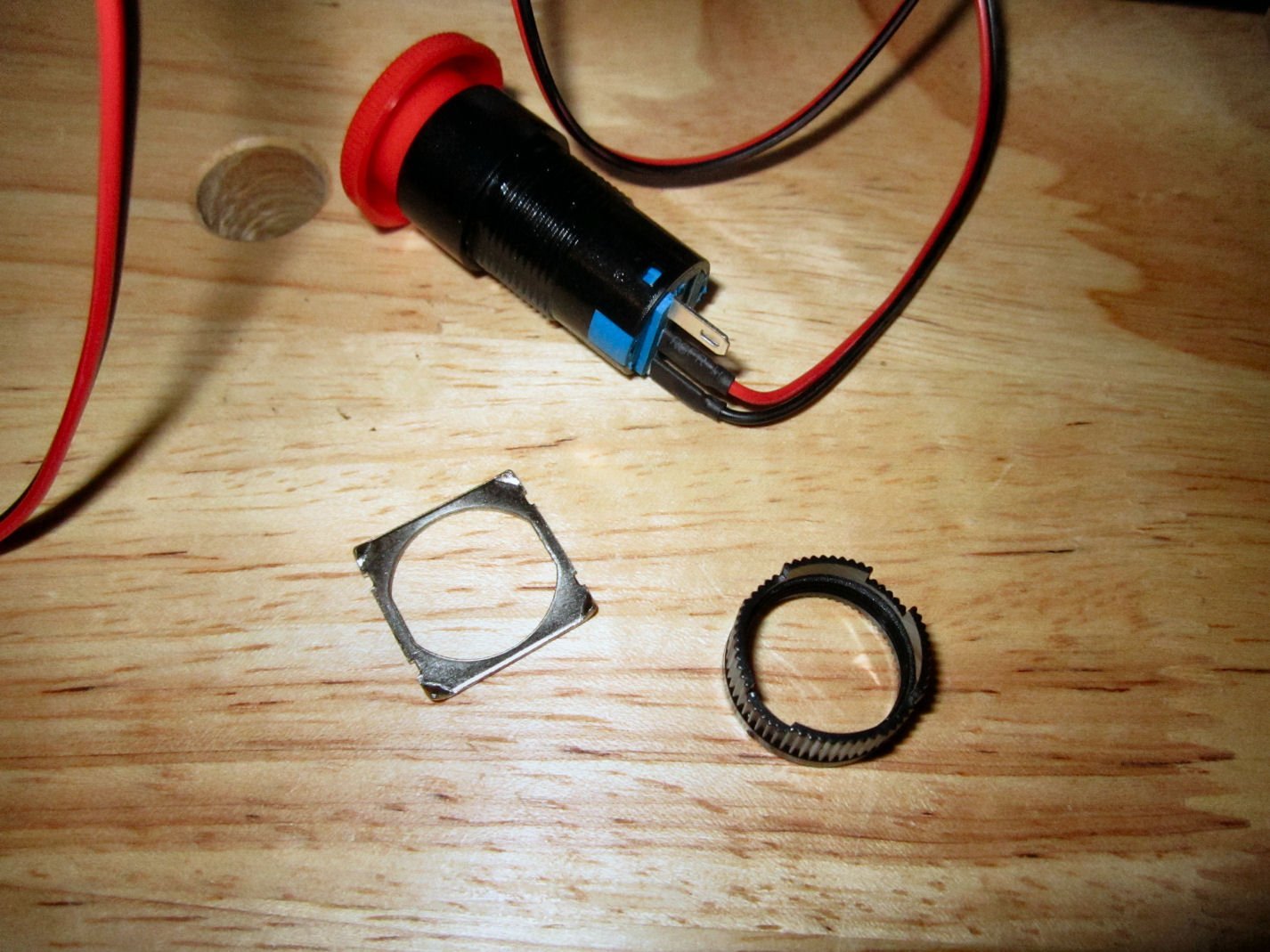
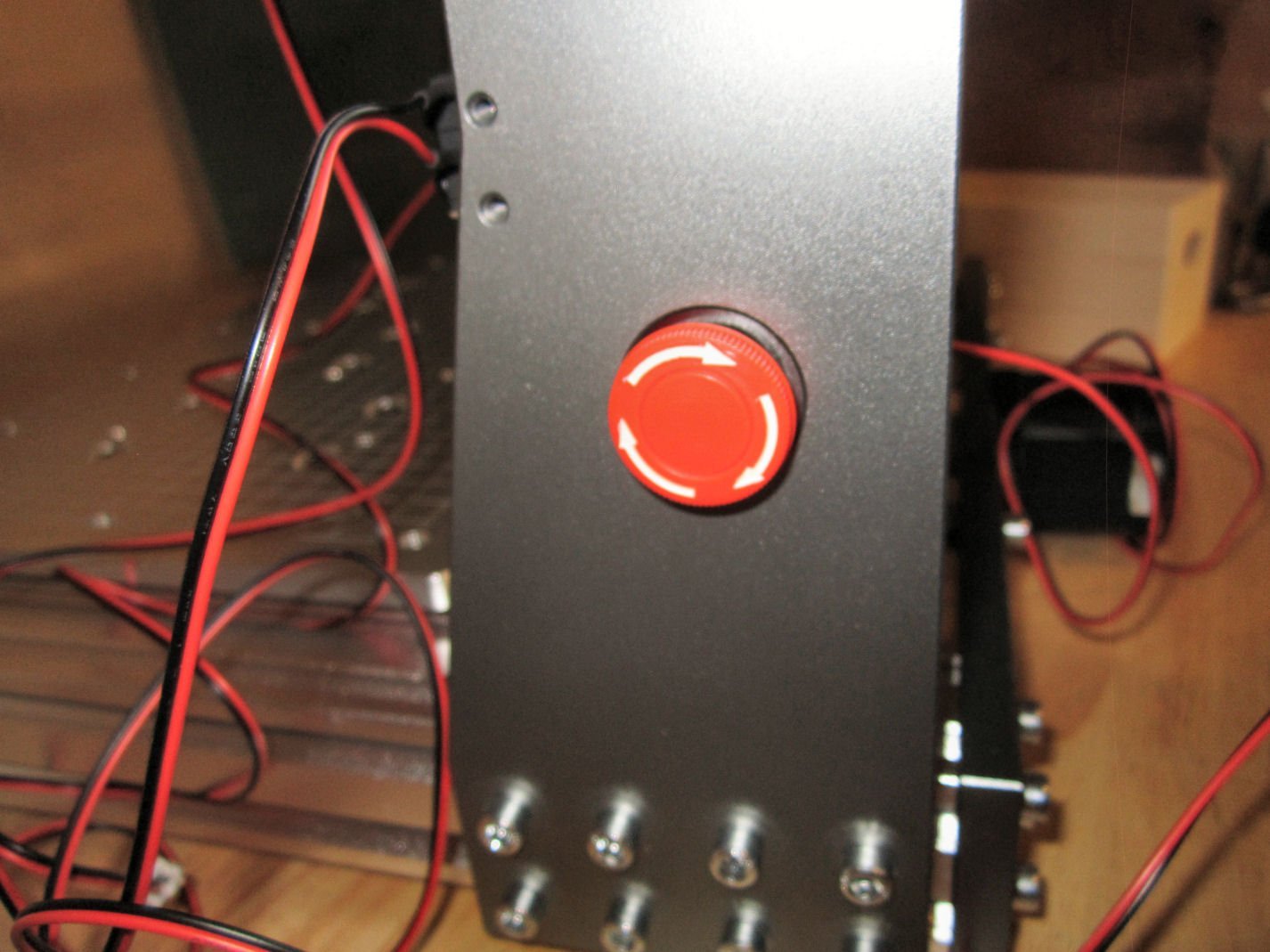
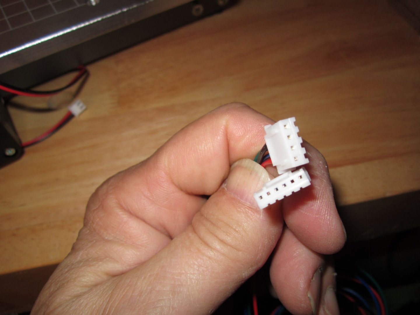
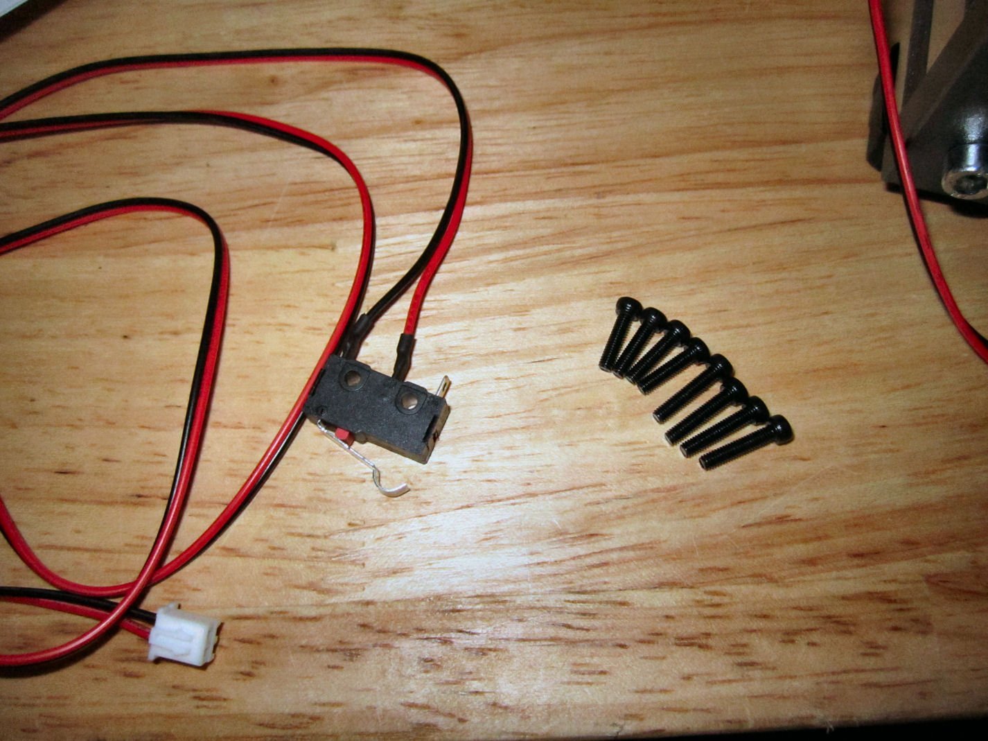
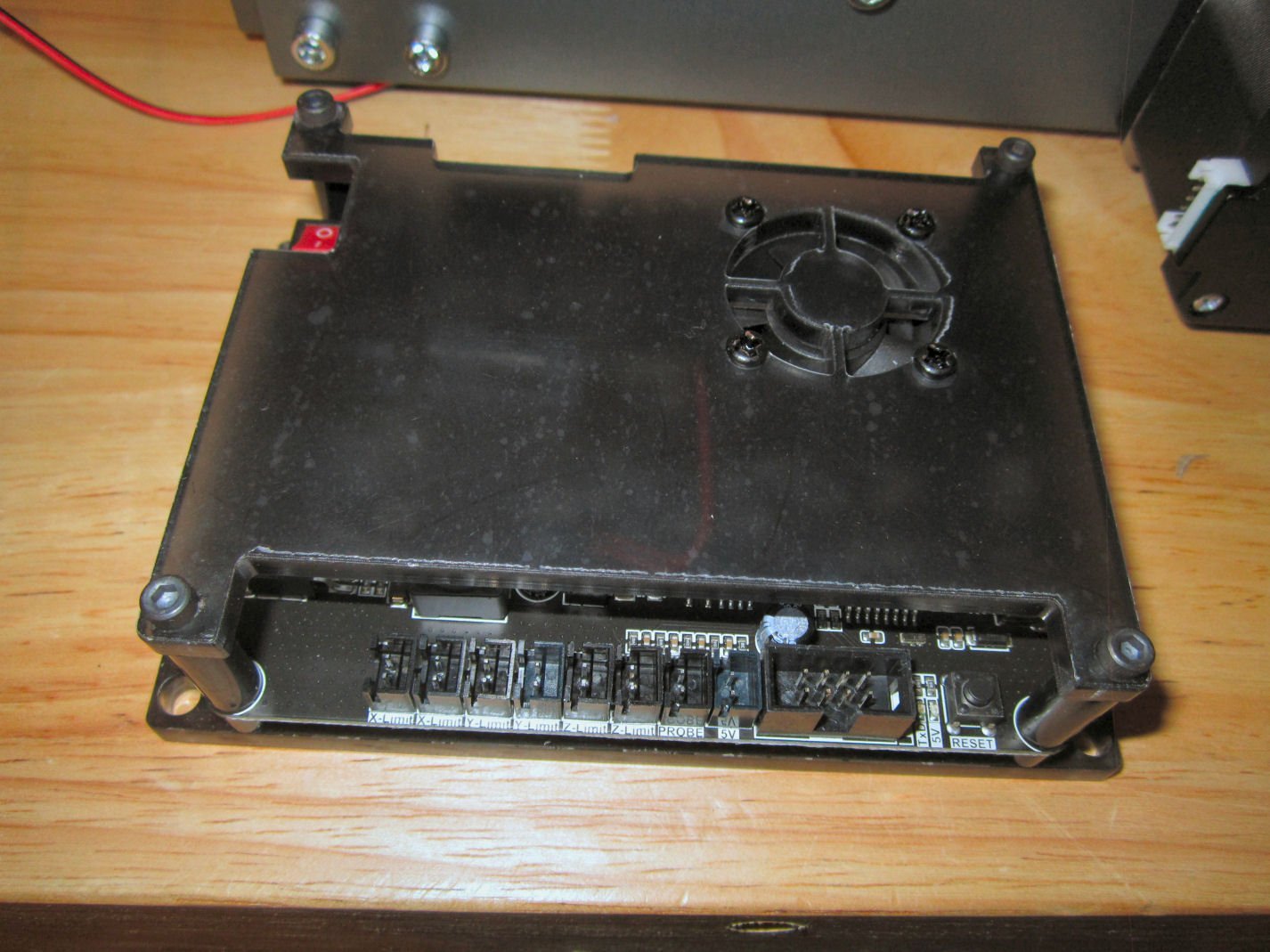
Part 006 The next few pictures show the various connections on the Controller board. The picture below shows the connectors at the top of the board. From left to right are: The Emergency Stop, The screw terminal connector for the power supply(L) and spindle motor power (R) (care must be taken that you get the polarities right! The positive (Red wire) connection is on the left and negative (Black wire) on the left, Connector for a SainSmart laser cutter head (not included), X- Axis servo motor, 2 Y-axis servo connections (you can use either for the servo on this unit, but the left hand one is recommended), and the Z-Axis servo motor. The second Y-Axis servo connector is for a future 4th Axis add-on. If it is like other brands, this will be used for a rotating holder that allows you to engrave/carve the surface of a round object, (bottle, glass, round wood blank, etc.) On the right hand side, Looking from the back of the router, is the USB connector for hooking the router to your computer. Along the bottom of the controller, from left to right, 2 X-Axis limit Switch connectors (put the cable from the limit switch in the first slot, in all cases), 2Y-Axis, 2 Z-Axis (put the optional bottom Z-Axis cable in the second slot, if used), the connector for the Z-Probe, used to determine the location of the tip of the cutter, a 5volt connector (not used, as far as I know), and the connector for the cable to the standalone control box. Here is another picture showing the whole area. There are no connections on the left side of the controller other than the On/Off switch. The instructions say to put the four “T” nuts used to mount the controller in the slots in the X-Axis supports, but there is an easier way. Install the screws in the holes in the controller, then screw on the “T” nuts. The nuts are what is called “hammer” nuts, because they resemble a hammer head. They are designed to slide in the slots then turn and lock into place vertically as the screw is tightened. So turn the nuts horizontally slip all four into the slots, then tighten them in place. Three of them worked, but I had to help one along with a screwdriver. Here is a picture of the controller installed. Next up is installing the Emergency Stop Switch. The instruction book shows this as being Factory Installed, but it does not come that way. The installation is simple, though. The switch comes with the washer and nut screwed onto the body. Note the direction the washer is on the switch, as it goes back on the same way (points toward the upright). Take them off and feed the switch and wire through the hole, with the button to the outside. Then reinstall the washer and nut. The next step is mounting the spindle motor. Slide it into the mount, and tighten the clamp screws. The motor should be placed so that about an equal amount of the case is above and below the mount. In the end, I chose to have the motor wires stick out on the left-hand side (unlike in the photo). I installed the Y-Axis limit switch and attached the cable to it. Then I ran it down the lower inside slot on the right hand frame extrusion. I temporarily taped it in place. Next was running the servo motor cables. These cables have two different size connections, the large connector attaches to the servo. All the cables are the same length. This picture shows the servo, power supply, spindle motor, and E-Stop cables installed into the controller. Here are the limit switch cables installed.


-
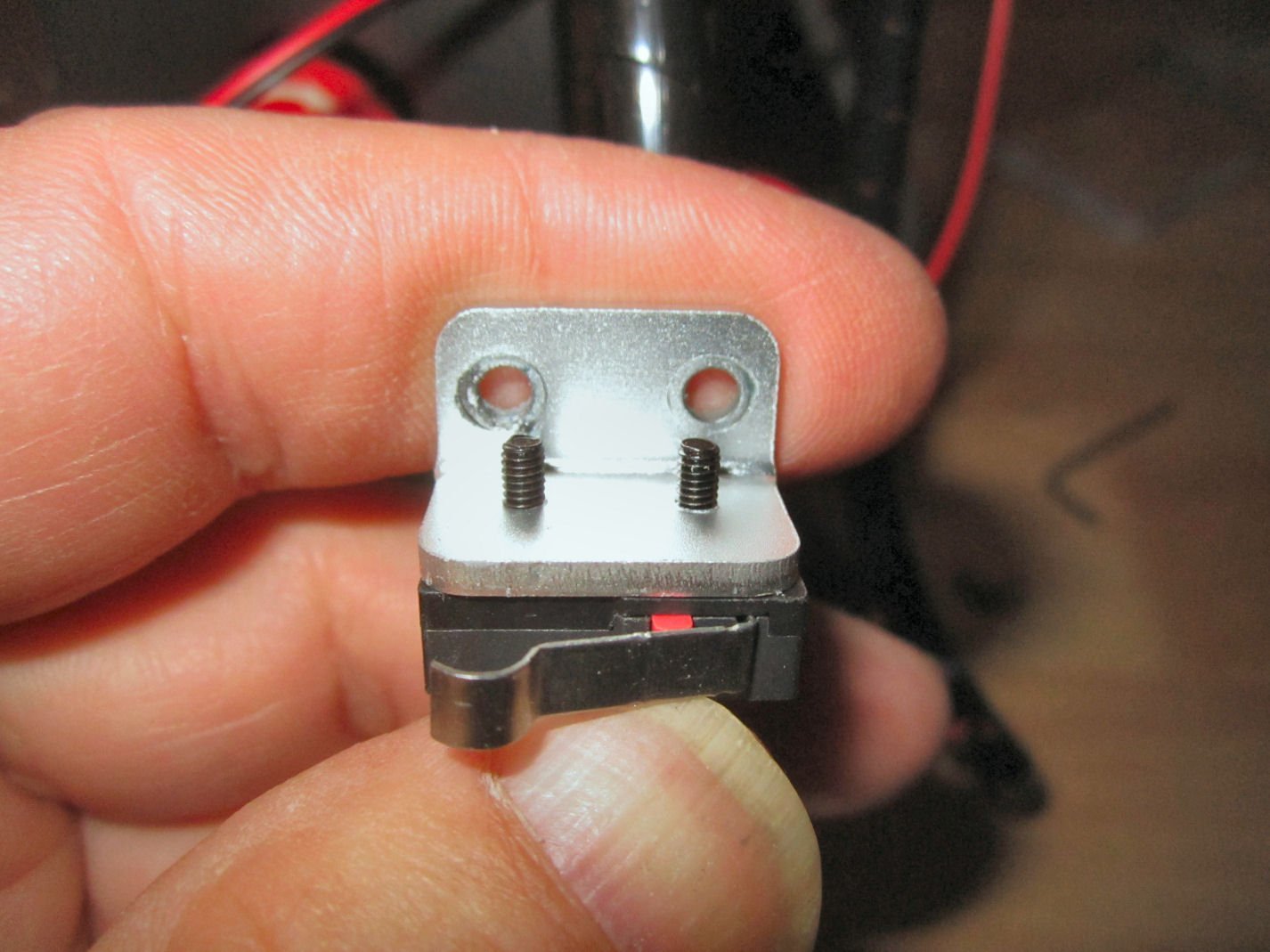
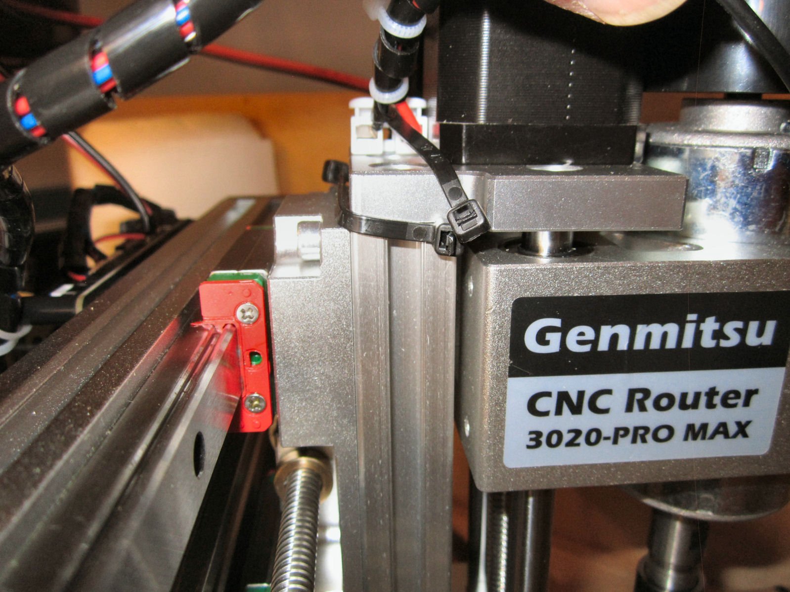
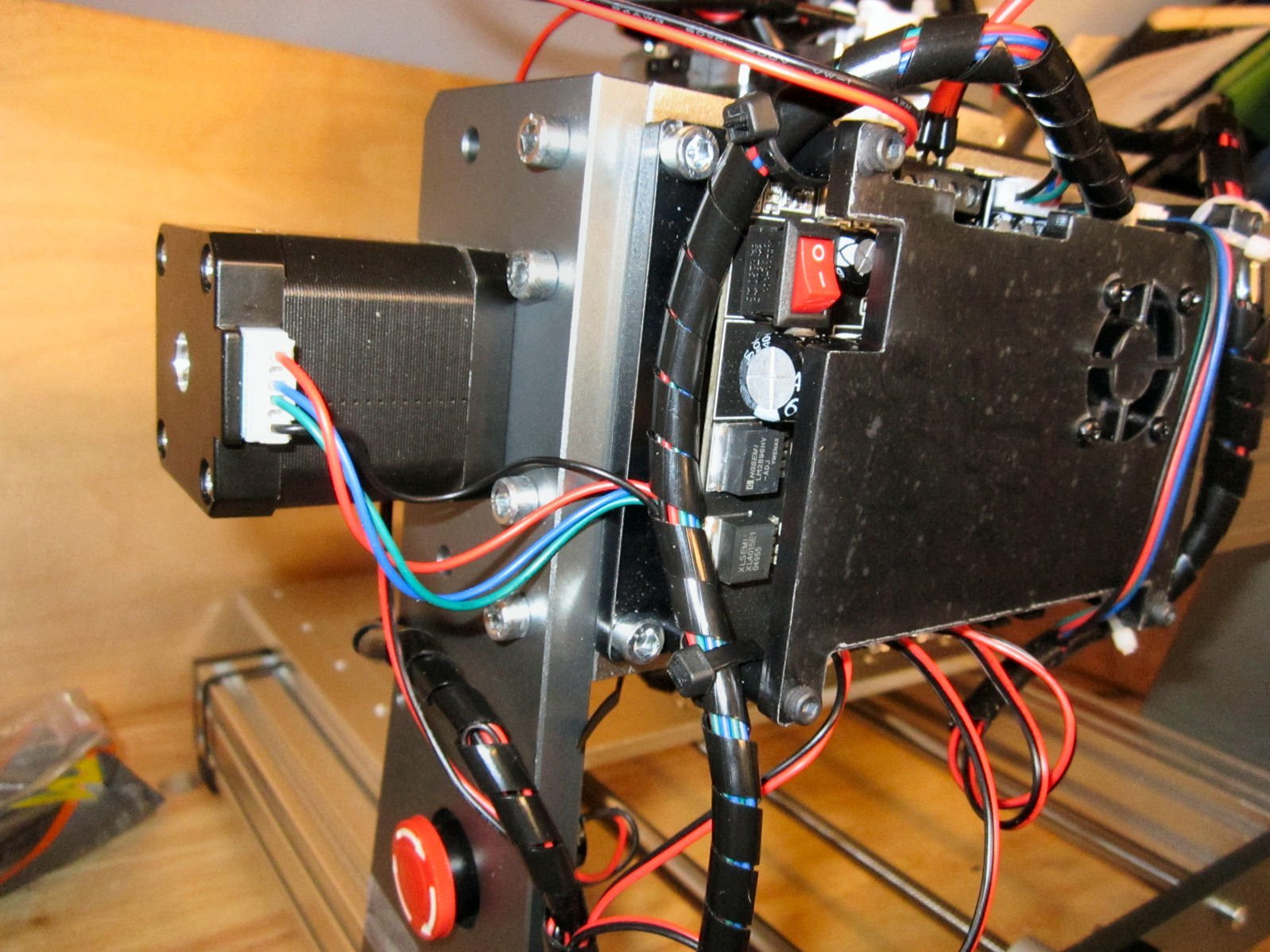
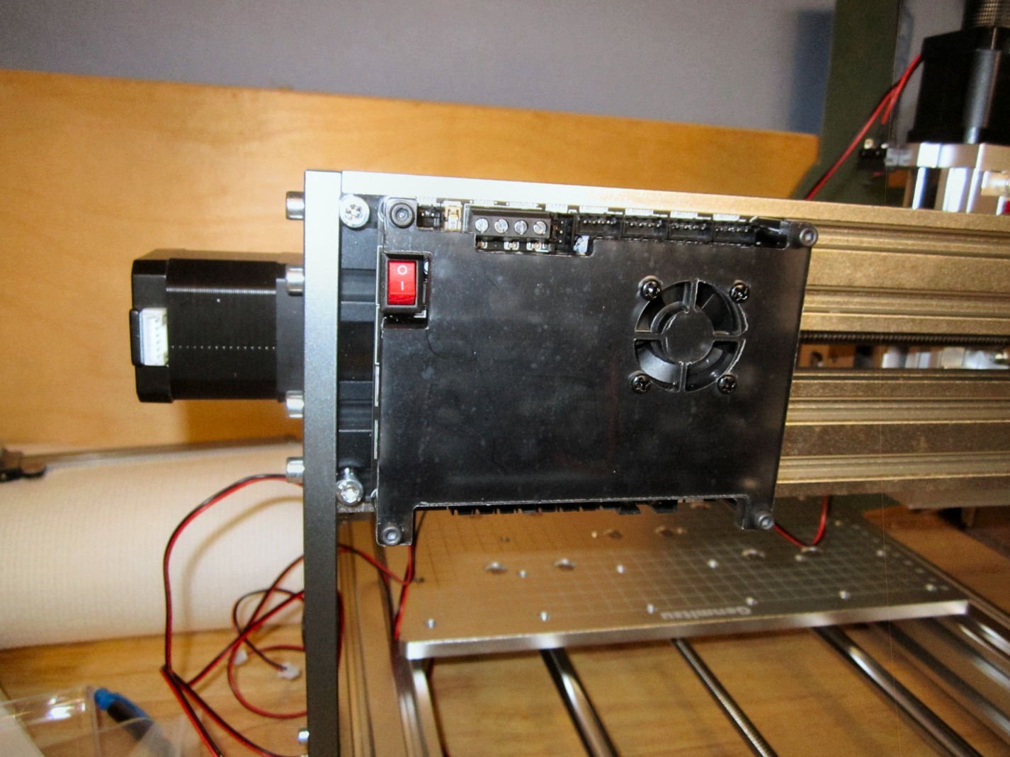
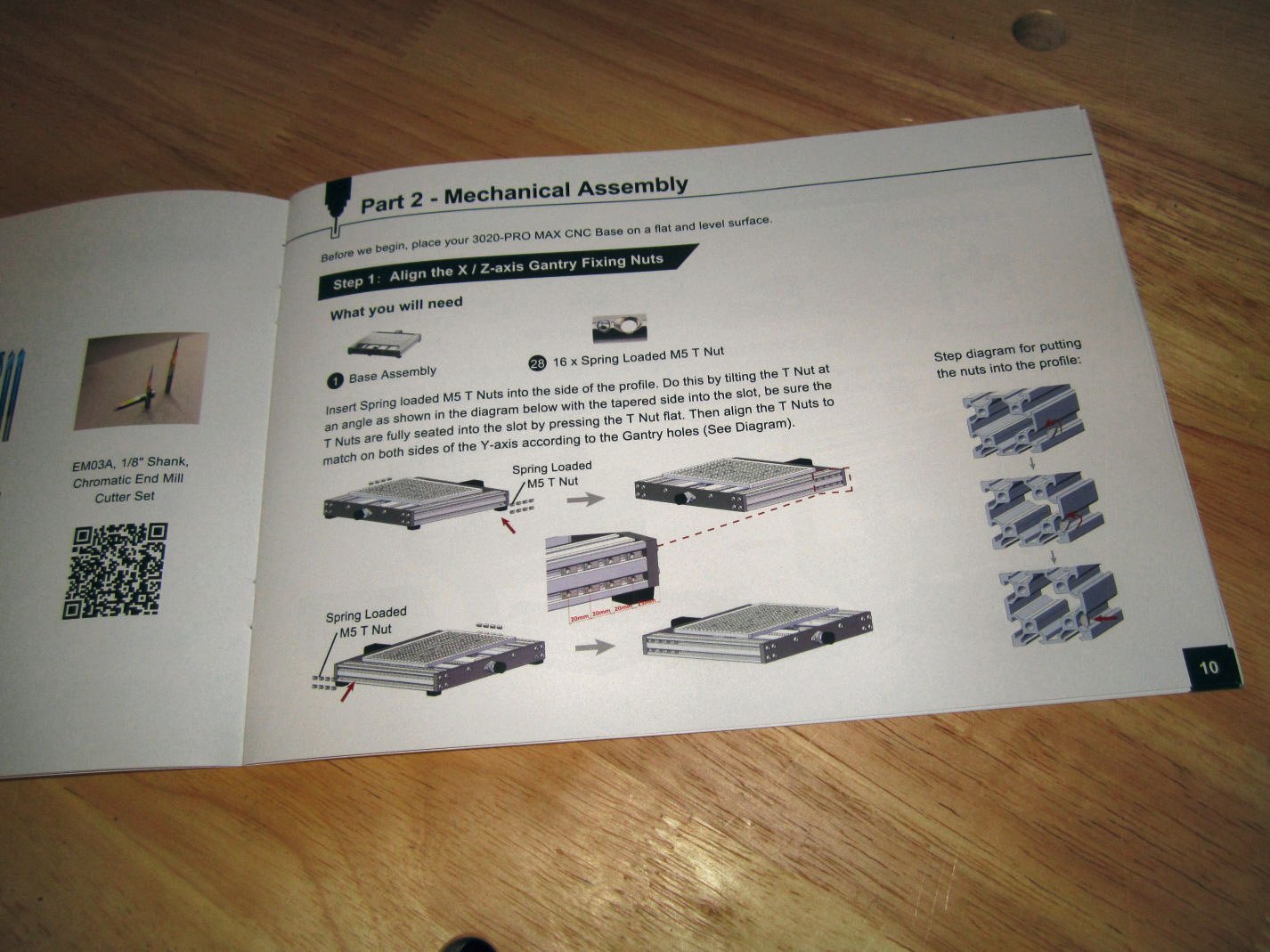
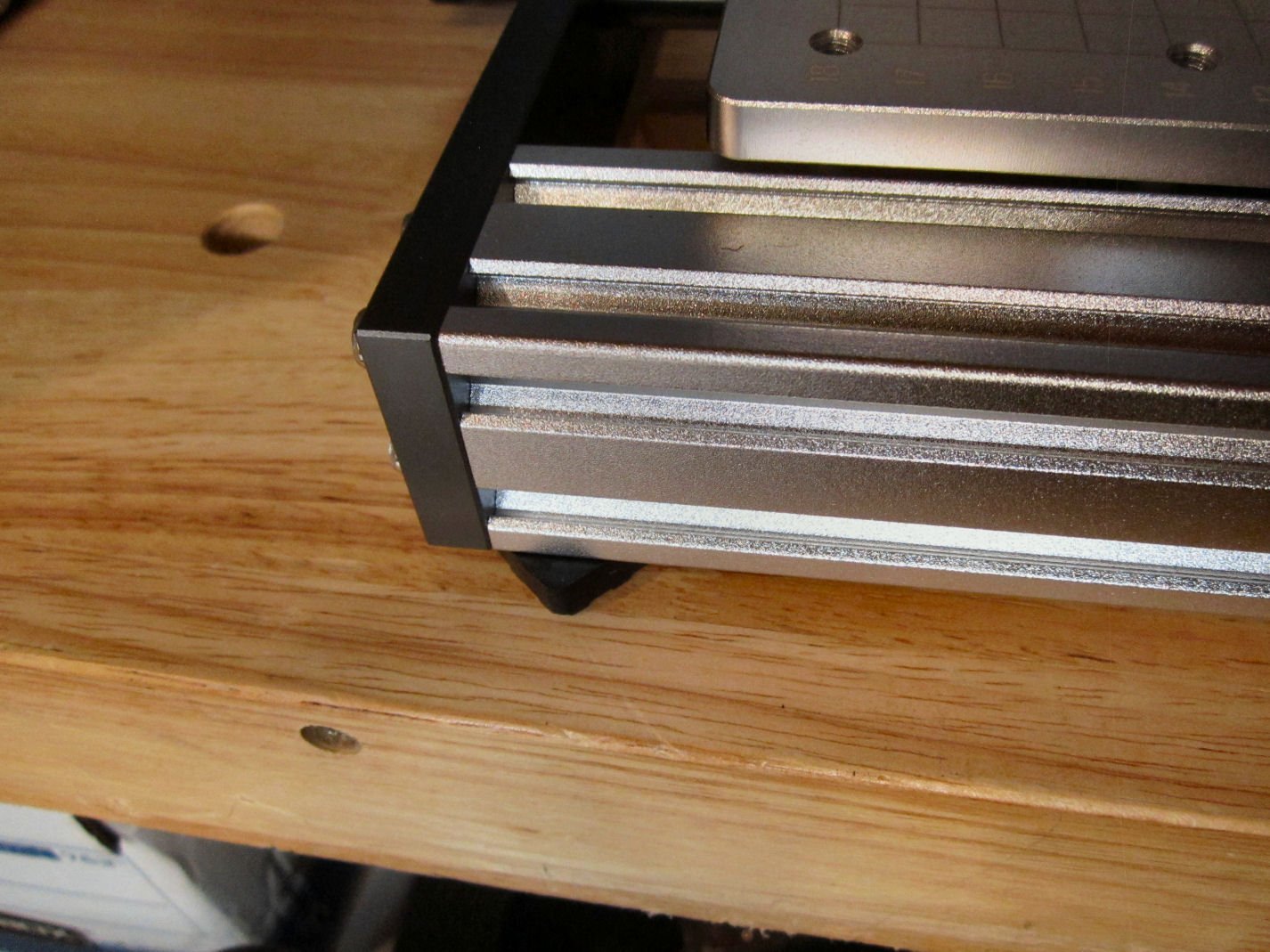
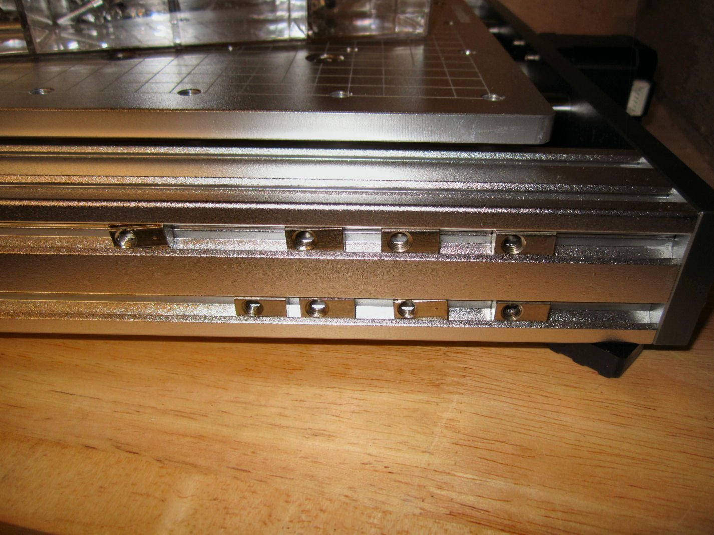
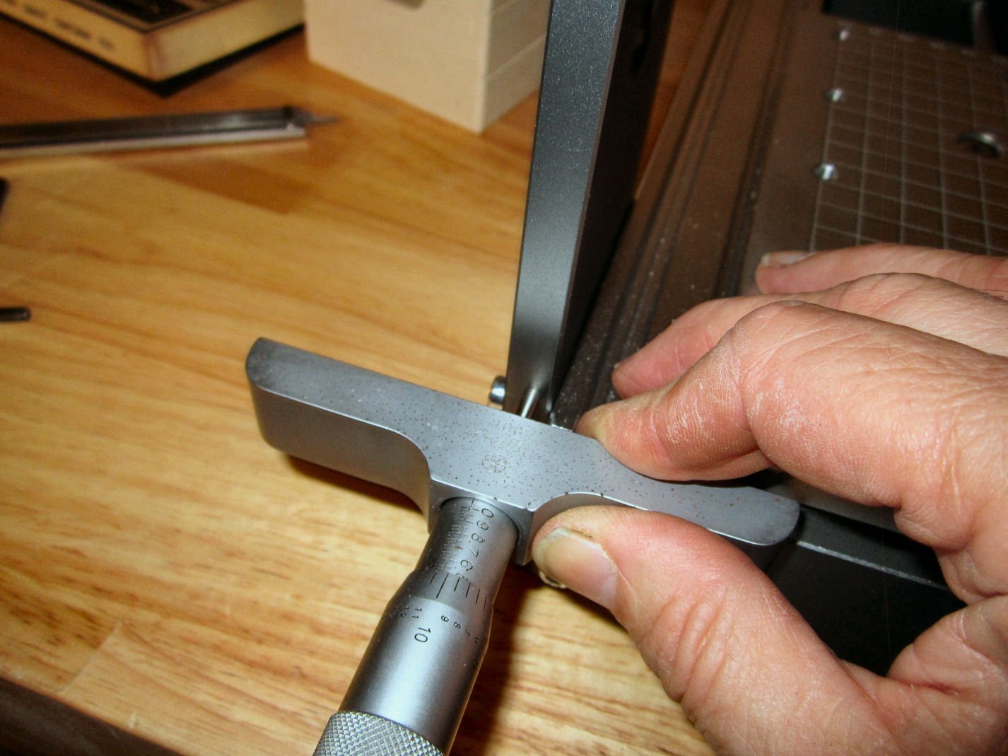
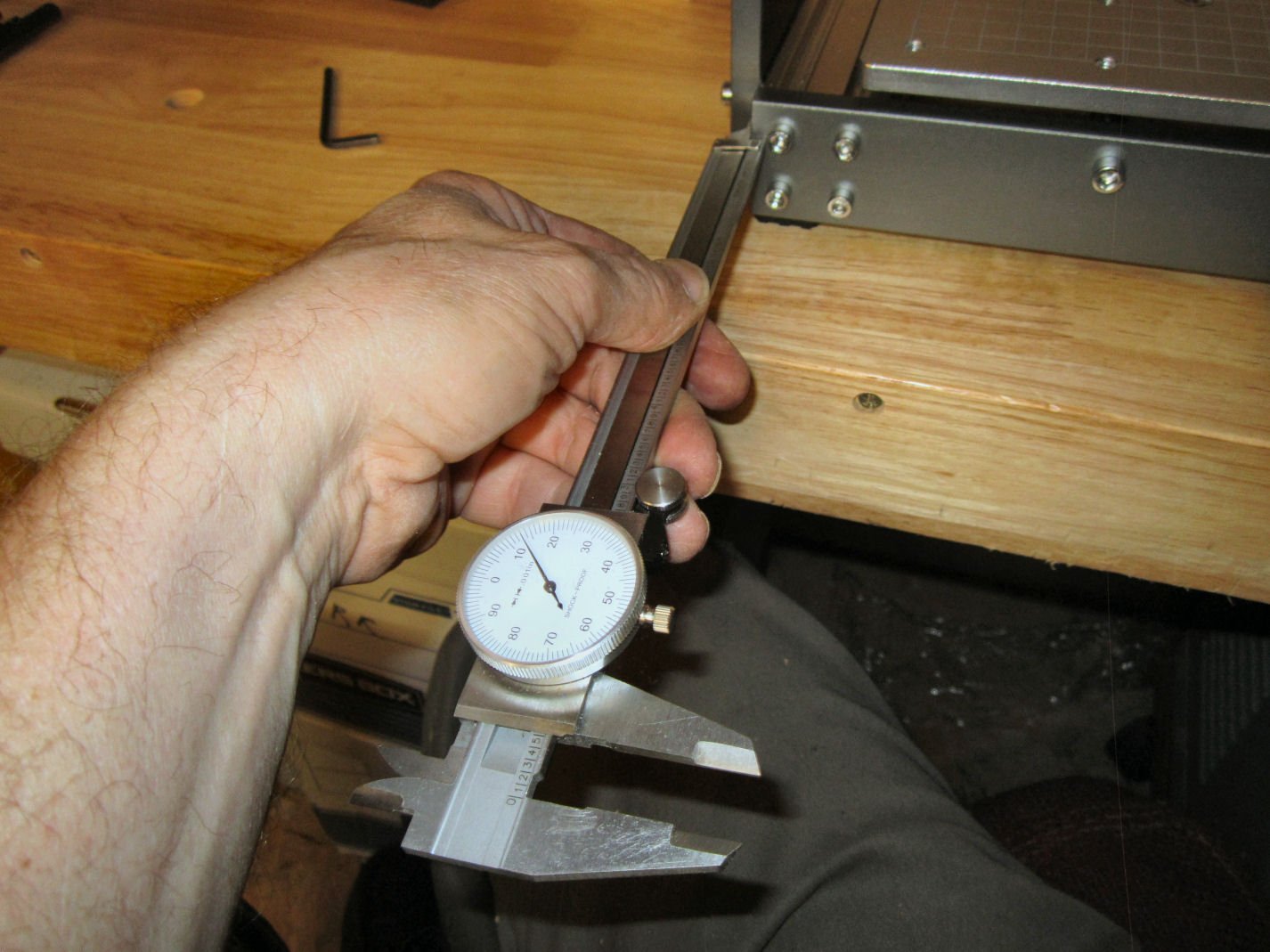
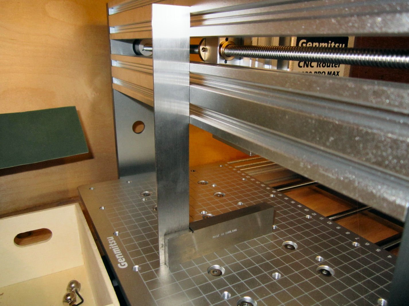
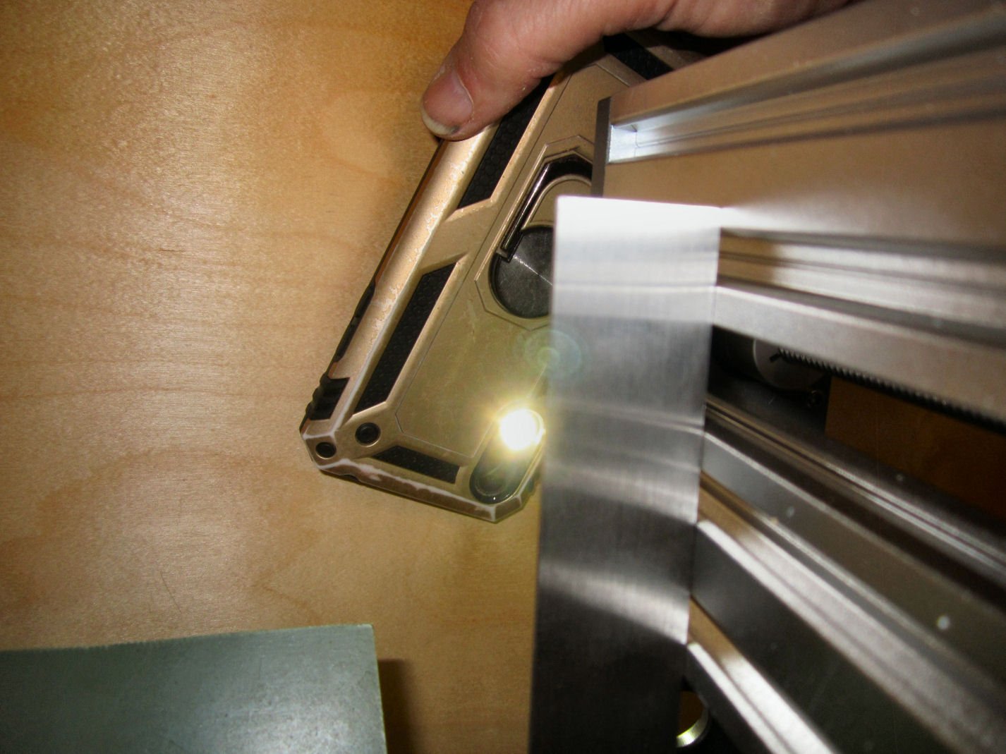
Part 005 This part starts the actual assembly of the 3020. The manual starts with inserting the 16 “T” nuts for attaching the upright onto the base. The “T” nuts have a spring loaded ball on the back, that is supposed to press against the back of the slot, and hold them in place. Well some of them actually worked this way! Some would hold the nut against the front, but not strongly enough to prevent them from sliding around, and some would not hold them at all! Starting on the right hand side, I put in four nuts each, into the two slots. The hole should face toward the front of the base. You can see two of the “Not Holding Worth a D**m” nuts at the left hand side of the upper row. I then used a dial caliper set at 20mm (0.787”) to space the back of the first row of nuts from the front (inside) of the rear cross piece. Then I spaced the nuts that same 20mm from each other (front of one nut to the front of the next one). The upper row has been spaced in the photo below (this shows the left hand side nuts). After adjusting they looked like this. Note: that I turned the rubber foot out to help support the back of the upright while I installed the bolts I repeated this on the other side, and then spent a lot of time spouting bad words, until all the bolts were installed and finger tight. Thankfully the better holding nuts were placed in the center four positions, but to get the outer nuts in place, I had to, at times, slide the uprights forward and back, then use a screw driver to push an errant nut back under, until the holes lined up, and then install that screw. Eventually the task was completed! Next comes spacing the back of the uprights 13mm (0.512") from the rear surface of the rear cross member. Now most videos I saw they just used a metric ruler to do this. Being a masochist and somewhat of a perfectionist. I used a machinist’s depth gauge! I hate myself sometimes, but I wanted as accurate a setup as possible. You could also use a caliper to do this. After more bad words, I managed to get the spacing within 0.001” of each other. The next step is to insure that the X-Axis supports are square with the table. I used a machinist’s square, set on the table. I used a light behind the square to check the alignment (no light shining through means the surfaces are in full contact), to check that the surfaces matched. One side was fine, but on the other the bottom support lined up, but both runners on the top support stood about the same distance away from the square (the ends of those two were not properly lined up). I loosened the two screws holding the end of that bar, and adjusted it to line up correctly. Once this was done I removed each of the 16 upright mounting bolts, one at a time, and applied blue thread locker (do not use the Red version! You will never get them apart again!) on them, to insure they don’t vibrate loose on me, in the future. I also did the same on the two X-Axis support bolts I loosened earlier. I was going to do this for all the factory assembled bolts, but the two I had to loosen were torqued down quite a bit, so I left well enough alone. At this point I checked the clearances on each axis for the amount of mechanical clearance the design had, in relation to how the limit switches were mounted. The Y and Z axis seemed like they allowed the most reasonable clearance for maximum travel. The X-Axis switch was in my option, set way too far into what would otherwise be useful cutting area. After I had gotten everything setup, I looked into this further. See Part 4 for my solution to this X-Axis limit switch problem. SainSmart supplies two different length screws to mount the limit switches to the brackets. The shorter screws are used for the Z-Axis switches. I also installed the optional lower Z-Axis switch. The next step is to install the controller board. At this time, I went ahead and installed it per factory instructions, but I will not leave it there for long. Putting the board in range of a fair amount of future saw dust, and metal chips is not a great idea, and the fact it has a cooling fan, just insures that any wood dust floating around will be sucked in! There is a similar problem with the power supply and its fan. In the next couple of weeks I’m going to build a full enclosure for the router, and will mount the control board and power supply on the outside of this enclosure. I can also tell you from the short time I’ve been playing with it, that the little On/Off switch on the controller (upper left in the above photo) is a pain to operate with it mounted on the back of the unit. I have designed the enclosure based on the one in the James Dean Designs YouTube video for the 3018 type router. Now that I have the actual 3020, I can see how well it would fit my enclosure design, and make any needed changes. The next part will show the installation of the controller board, which will complete the assembly of the router body, and we start the demon octopus of wiring everything up!! (Hint, more bad words!)

-
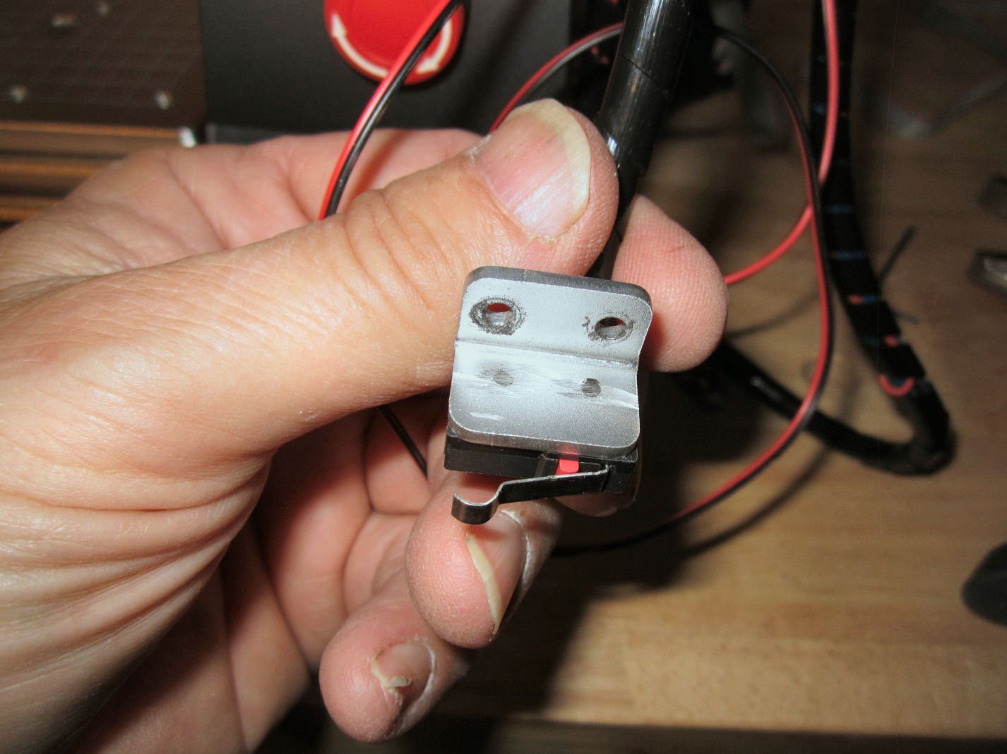
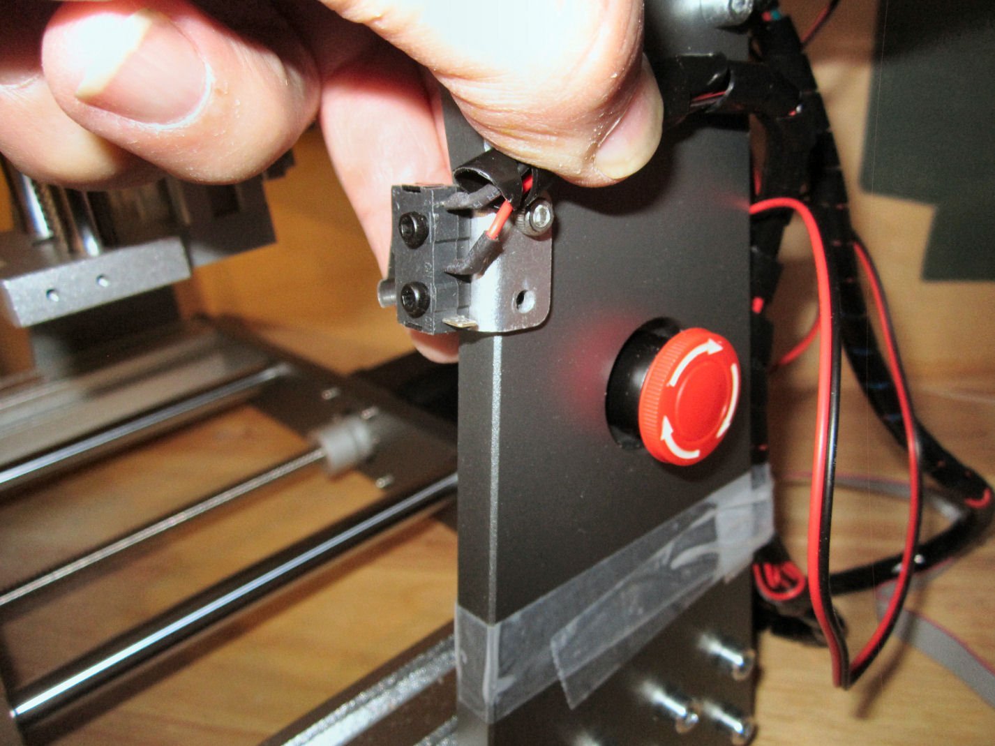
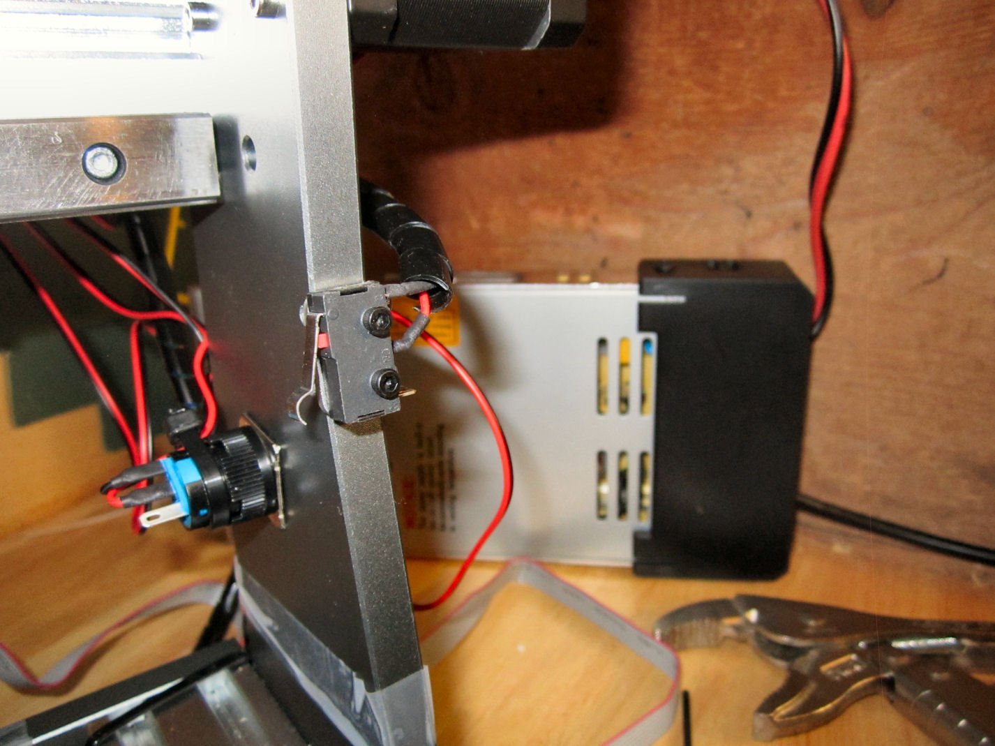
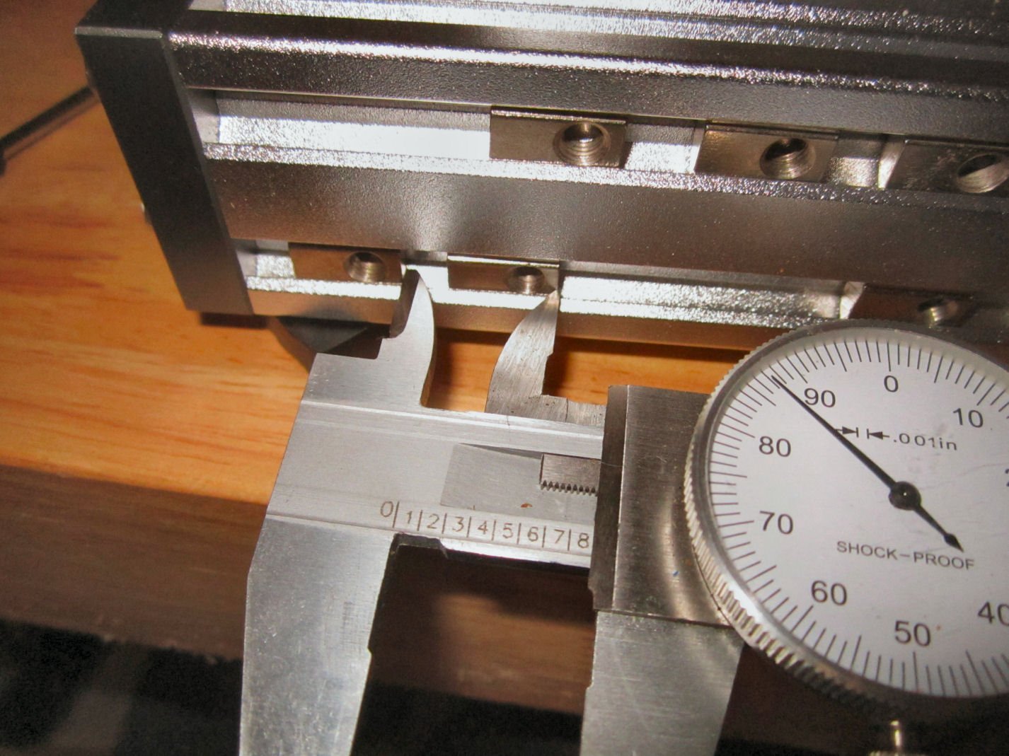
Part 004 – A modification you may want to make to the X-Axis This section was supposed to be the start of assembling the router, but I have a modification you might want to make, before everything is assembled, and awkward to handle. First I have been quoting the thickness of the uprights at 12mm. I measured them today and they are 10mm. I read that they are 2mm thicker than those on the Prover, but don’t know if the write-up was wrong, or if the Prover uprights are 8mm. As the unit is delivered the Y and Z-Axis limit switches are built so that they contact at what I would say is close to the mechanical limits, so they are good. If you buy another Y-Axis bracket and switch, they will fit at that end, with the same clearances as the existing setup. Once again a good arrangement. The X-Axis limit switch, however, is set far from where the mechanical limit of the spindle assembly can go. The X-Axis limit switch mount protrudes 0.563” from the right side upright, and with the switch mounted, the switch contacts 16.18mm (0.637”) from the upright (the limit switch has a .127mm (+ 0.005”) tolerance when the spindle goes to “Home”). The mechanical interference with the spindle assembly with the upright is 4mm! This means you have lost 12mm of usable cutter travel, with the limit switch placed where it is! Assuming in the future you use the same hardware to install a limit switch on the other end of the X-Axis, this means you lose almost 24mm (about an 1”) of available cutting length along that axis! I ran an experiment by moving the mounting of the bracket to the outside of the upright, rather than the inside. With the bracket mounted here the spindle gained about 12mm (0.470”) of additional travel, while still stopping with about 1/8 of an inch of clearance before the spindle assembly would hit the coupling nut on that side. Assuming you bought a switch and bracket like those used in the kit, and mounted them in this fashion, you would gain 24mm or a little less than 1” of usable travel, while still having the protection of limit switches at both ends. This takes the usable travel from about 265mm (10.4”) (with two switched mount in the factory way) to about 289mm (11.3”) almost 10%! If you are interested in making this modification, I detail the changes below. The mounting holes in the upright are drilled and tapped all the way through, so no modification to it is needed. Be aware that this may void your warranty! First I removed the bracket with the limit switch installed, then I used a cutoff wheel to cut the protruding switch mounting bolts even with the inside of the bracket. This allows the bracket to fit tightly against the front surface of the upright. Next I placed the bracket in place. The upper bolt hole fit correctly, but the upright angles forward at this point, and the lower hole was slightly offset. Using a round file, it extended the hole to fit. Then I installed the other screw. I had to cut the spiral wire wrap a little shorter (see my assembly write-ups coming soon), and tape the wire for the lower Z-Axis limit switch down. I will make a more permanent hold down later. I need to go to the hardware store and see what they have available. I moved and “Homed” the spindle several times, to insure that this was a safe modification. I hope this helps those buying this router! The assembly will start in Part 5.