thibaultron
-
Posts
2,954 -
Joined
-
Last visited
Content Type
Profiles
Forums
Gallery
Events
Everything posted by thibaultron
-
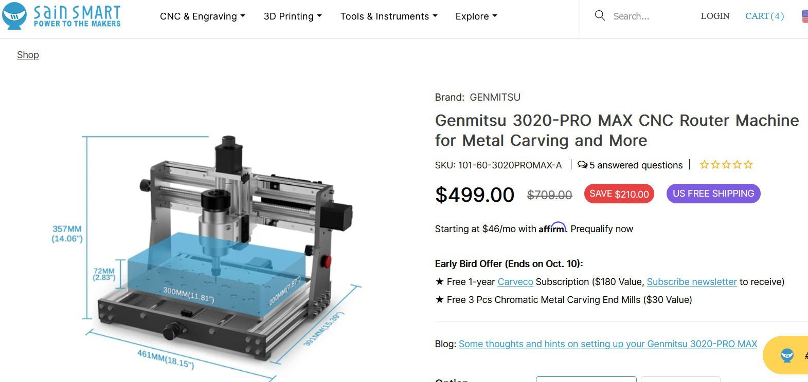
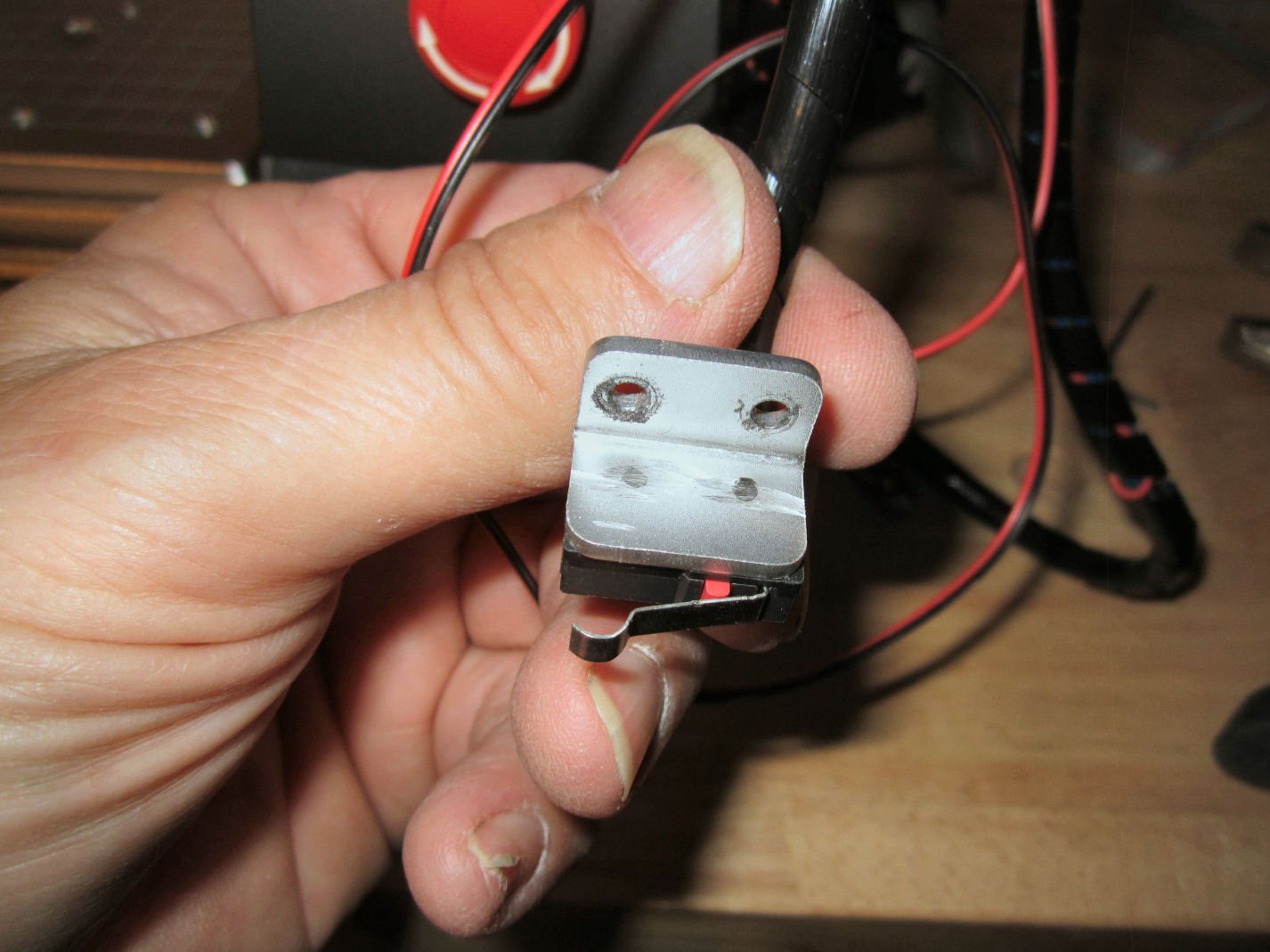
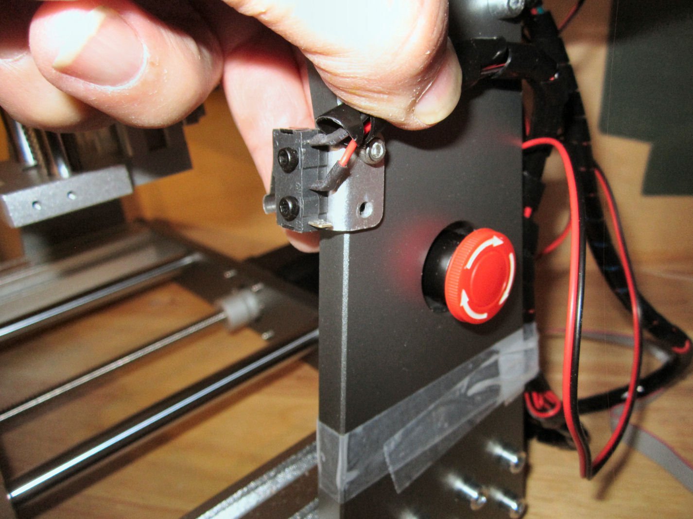
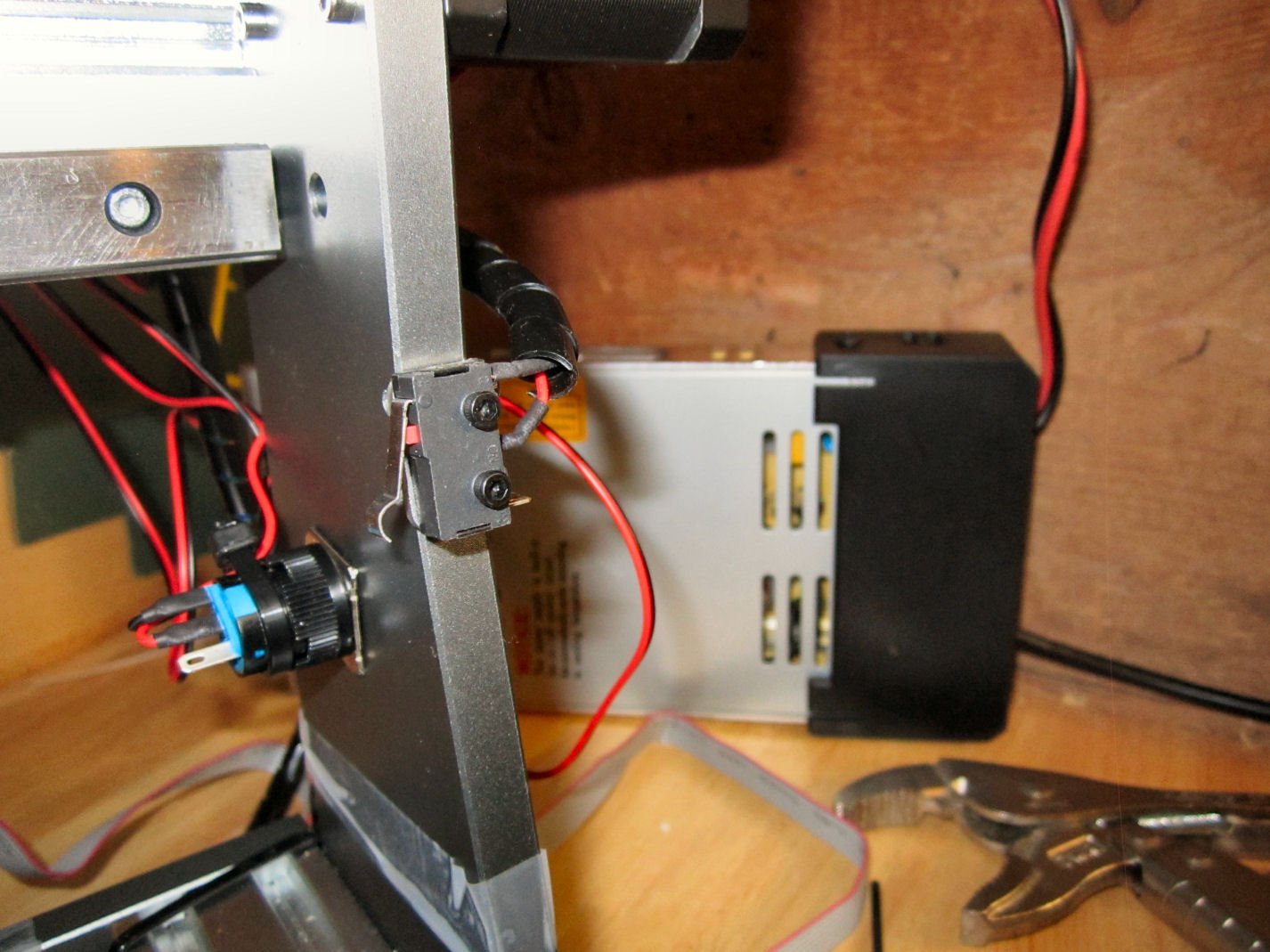
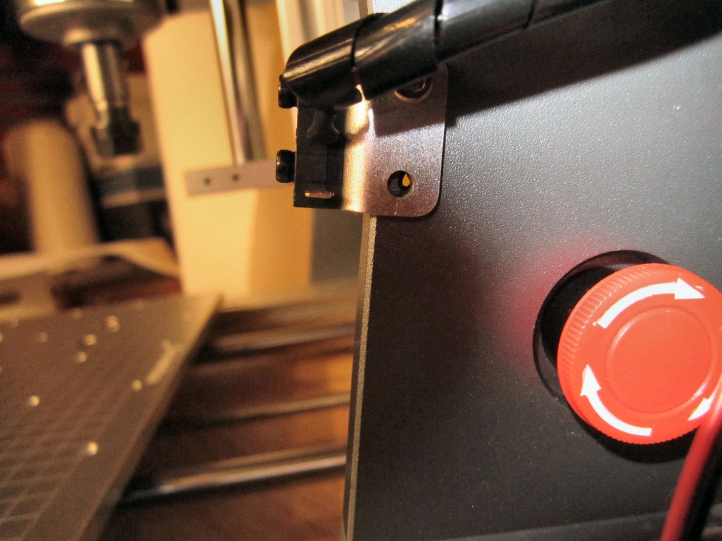
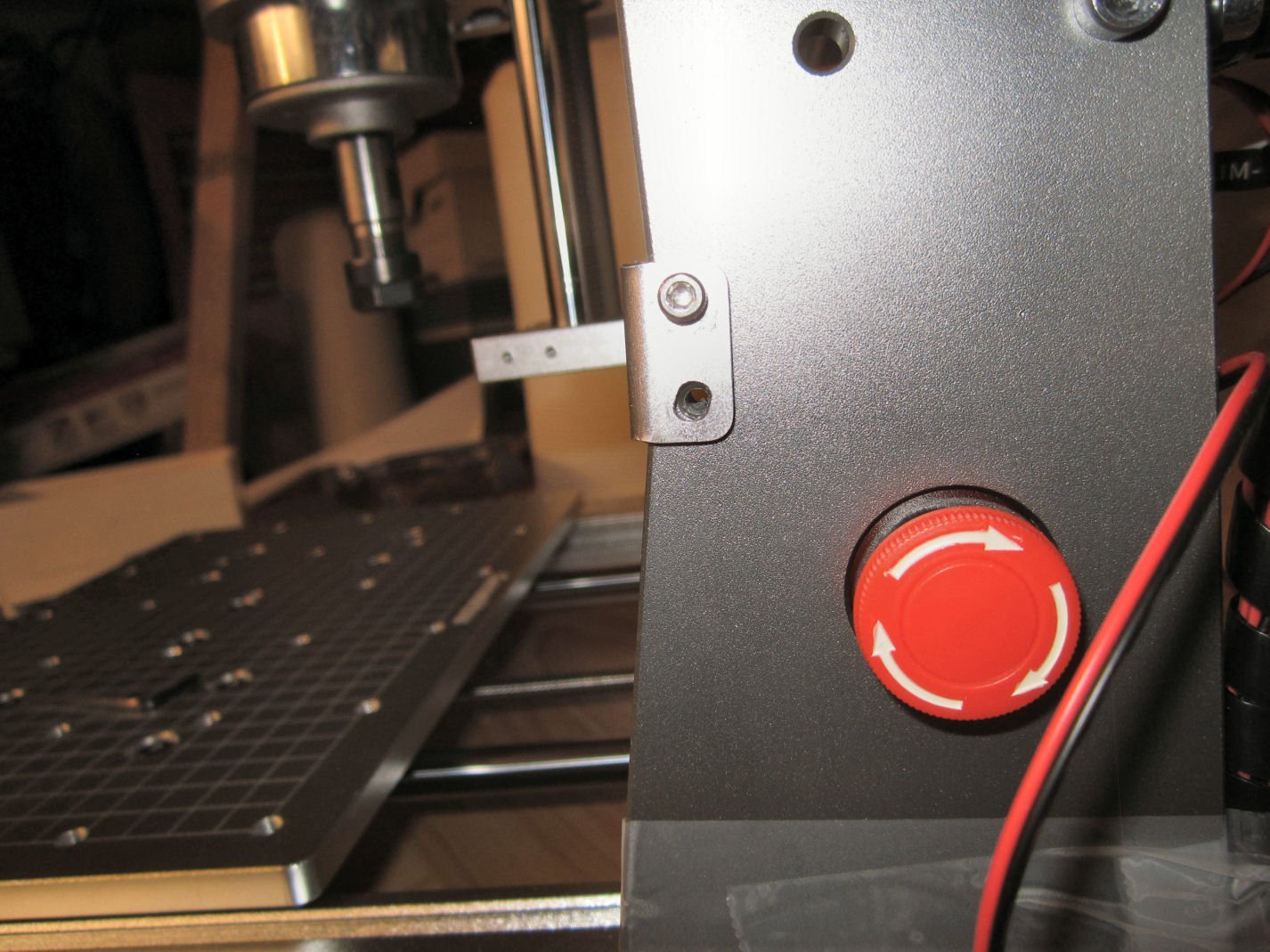
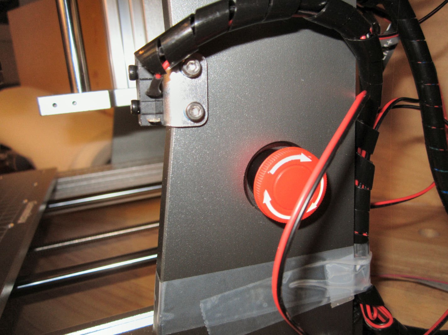
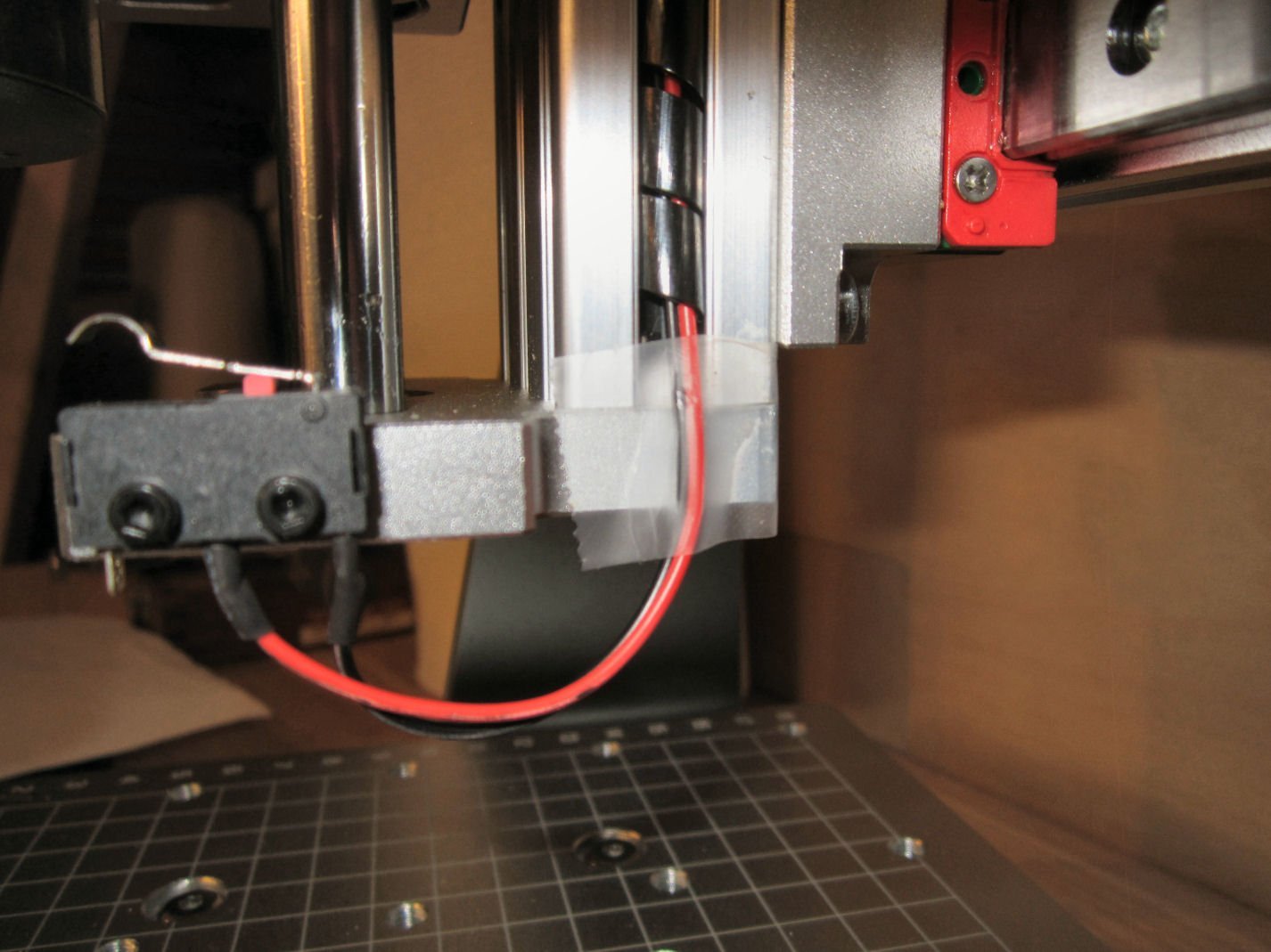
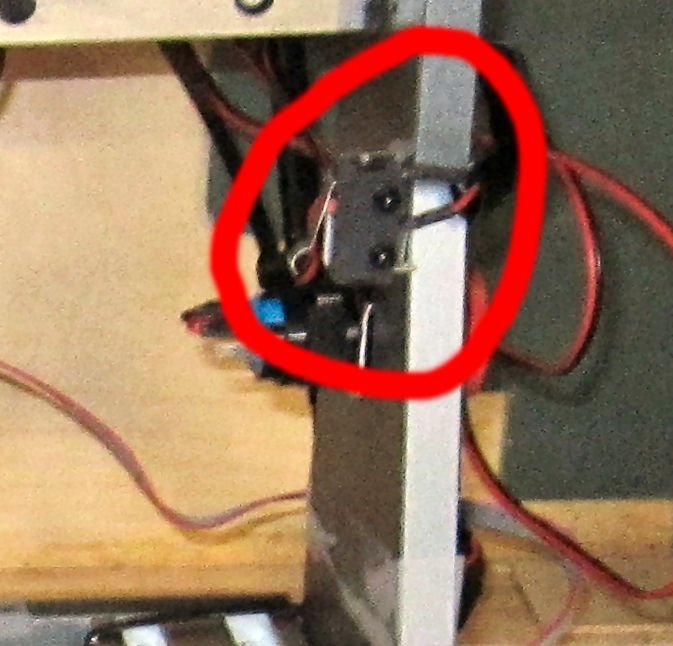
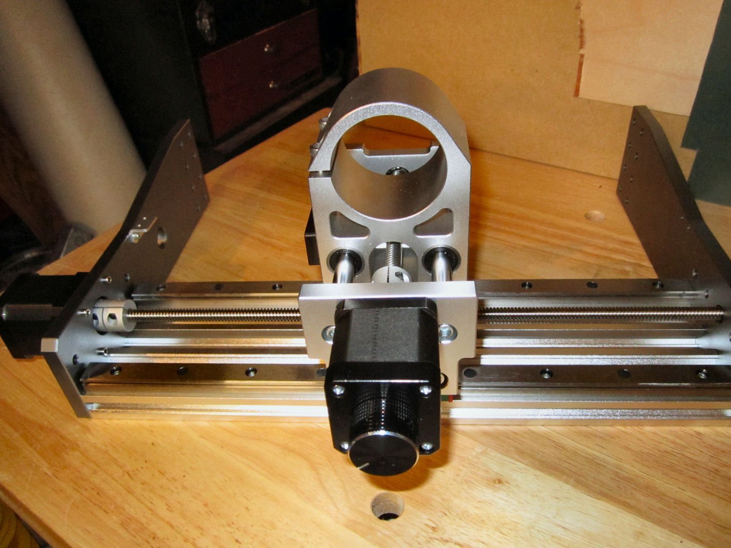
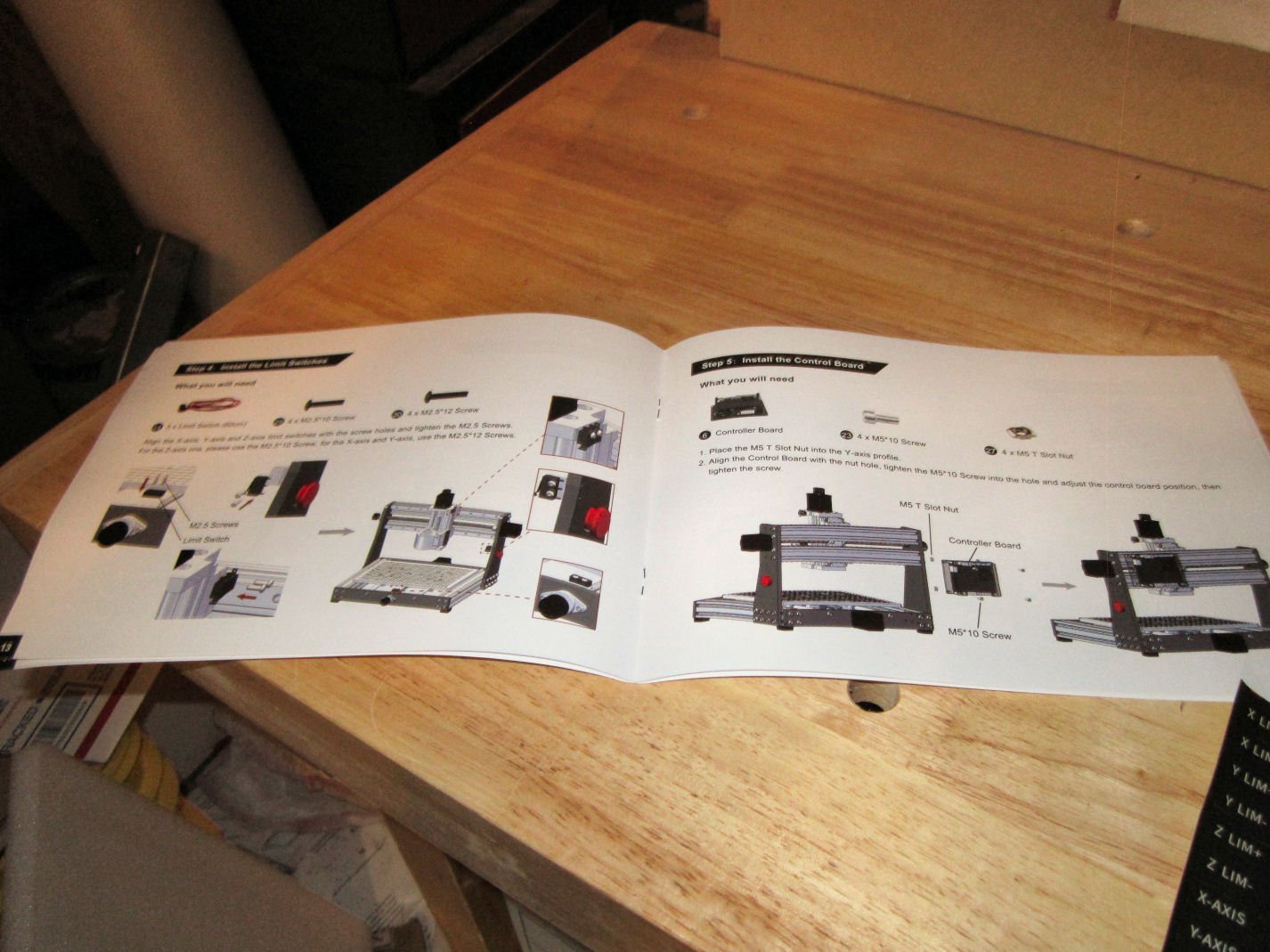
 Part 004 – A modification you may want to make to the X-Axis This section was supposed to be the start of assembling the router, but I have a modification you might want to make, before everything is assembled, and awkward to handle. First I have been quoting the thickness of the uprights at 12mm. I measured them today and they are 10mm. I read that they are 2mm thicker than those on the Prover, but don’t know if the write-up was wrong, or if the Prover uprights are 8mm. As the unit is delivered the Y and Z-Axis limit switches are built so that they contact at what I would say is close to the mechanical limits, so they are good. If you buy another Y-Axis bracket and switch, they will fit at that end, with the same clearances as the existing setup. Once again a good arrangement. The X-Axis limit switch, however, is set far from where the mechanical limit of the spindle assembly can go. The X-Axis limit switch mount protrudes 0.563” from the right side upright, and with the switch mounted, the switch contacts 16.18mm (0.637”) from the upright (the limit switch has a .127mm (+ 0.005”) tolerance when the spindle goes to “Home”). The mechanical interference with the spindle assembly with the upright is 4mm! This means you have lost 12mm of usable cutter travel, with the limit switch placed where it is! Assuming in the future you use the same hardware to install a limit switch on the other end of the X-Axis, this means you lose almost 24mm (about an 1”) of available cutting length along that axis! I ran an experiment by moving the mounting of the bracket to the outside of the upright, rather than the inside. With the bracket mounted here the spindle gained about 12mm (0.470”) of additional travel, while still stopping with about 1/8 of an inch of clearance before the spindle assembly would hit the coupling nut on that side. Assuming you bought a switch and bracket like those used in the kit, and mounted them in this fashion, you would gain 24mm or a little less than 1” of usable travel, while still having the protection of limit switches at both ends. This takes the usable travel from about 265mm (10.4”) (with two switched mount in the factory way) to about 289mm (11.3”) almost 10%! If you are interested in making this modification, I detail the changes below. The mounting holes in the upright are drilled and tapped all the way through, so no modification to it is needed. Be aware that this may void your warranty! First I removed the bracket with the limit switch installed, then I used a cutoff wheel to cut the protruding switch mounting bolts even with the inside of the bracket. This allows the bracket to fit tightly against the front surface of the upright. Next I placed the bracket in place. The upper bolt hole fit correctly, but the upright angles forward at this point, and the lower hole was slightly offset. Using a round file, it extended the hole to fit. Then I installed the other screw. I had to cut the spiral wire wrap a little shorter (see my assembly write-ups coming soon), and tape the wire for the lower Z-Axis limit switch down. I will make a more permanent hold down later. I need to go to the hardware store and see what they have available. I moved and “Homed” the spindle several times, to insure that this was a safe modification. I hope this helps those buying this router! The assembly will start in Part 5.
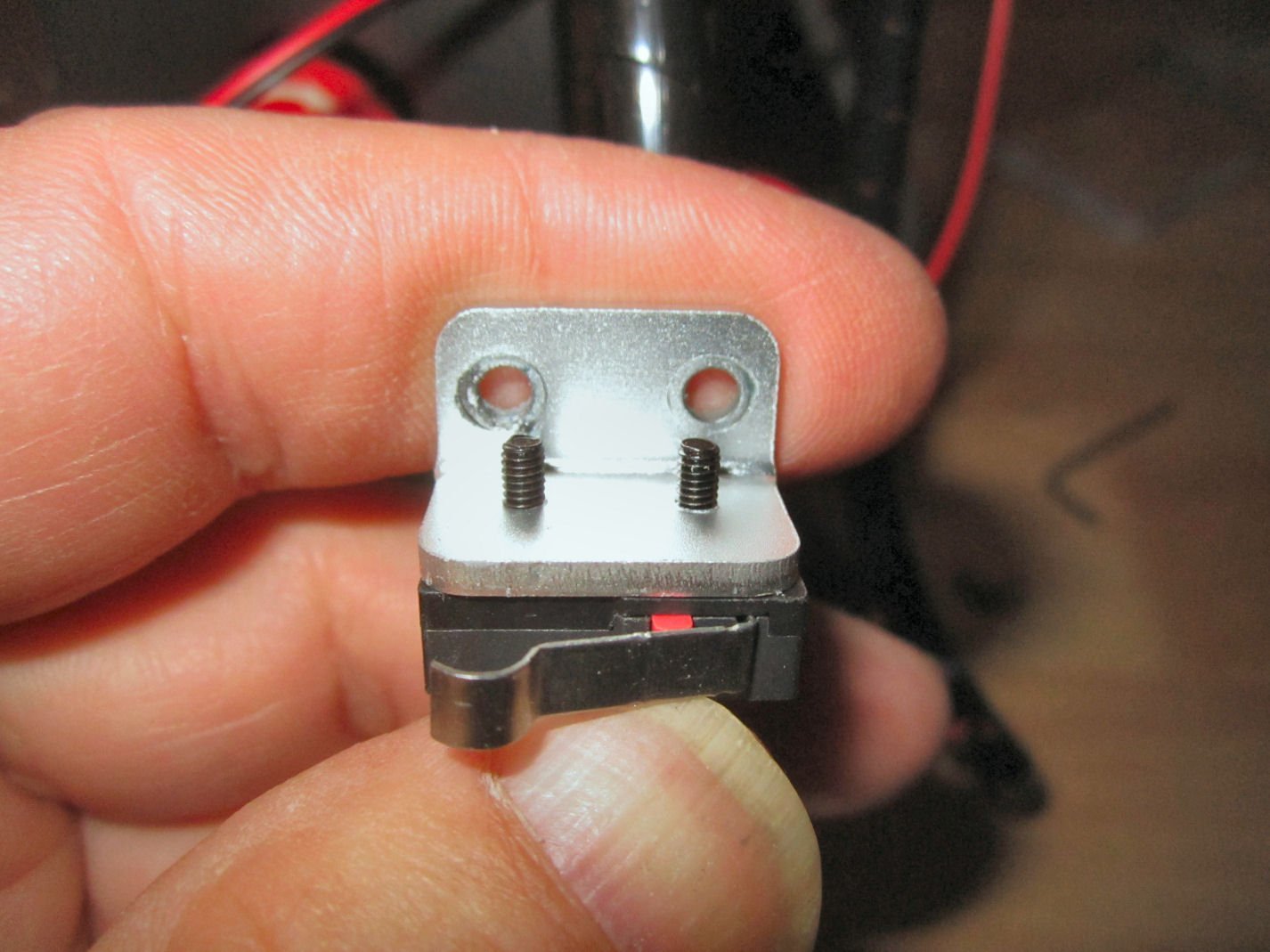
-
For those who might be interested in these CNC routers, I recommend James Dean Designs videos, on YouTube. He has a great series on setting up and using various CNC routers. Start with the 3018 videos, even if you will be getting a 3020. Operations on both machines will be similar.
-
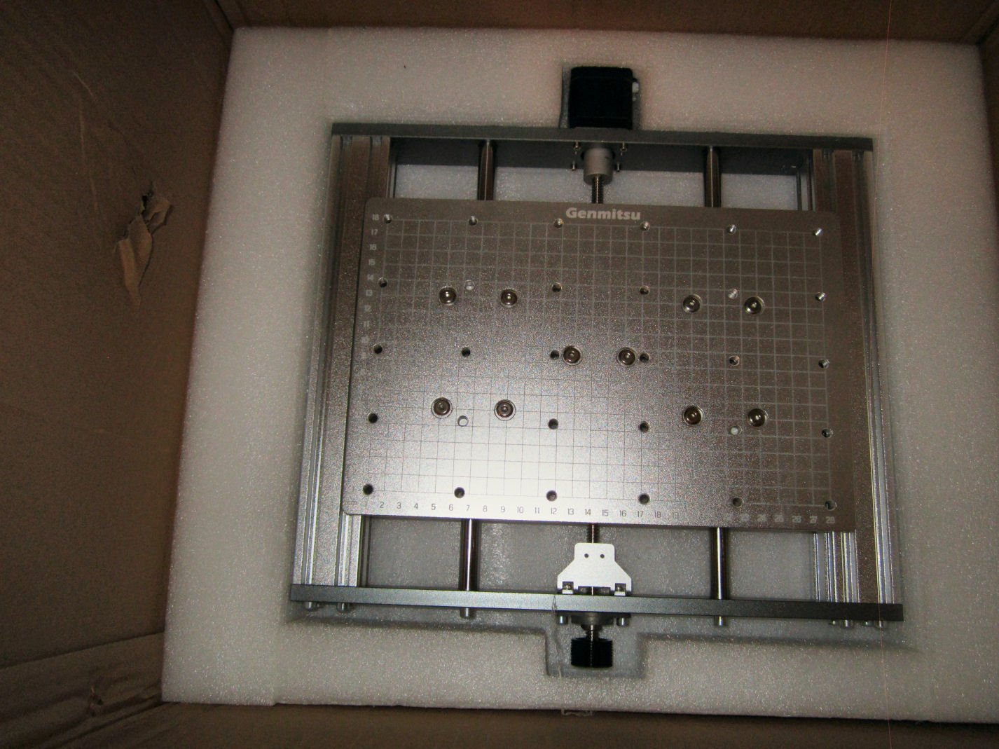
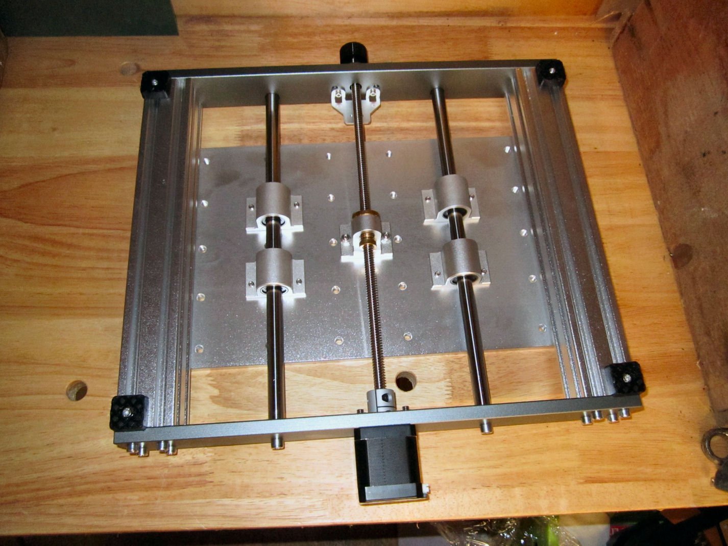
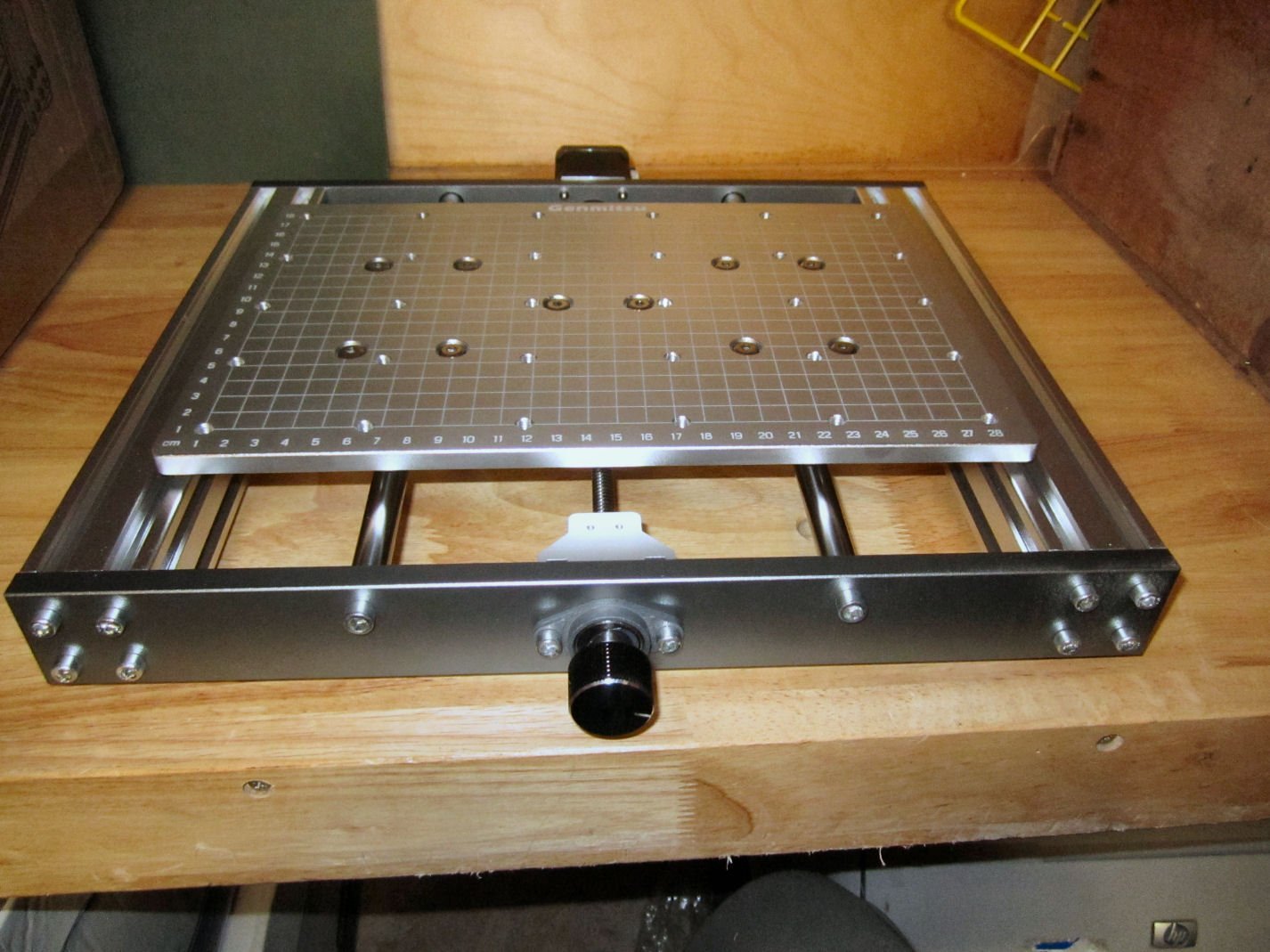
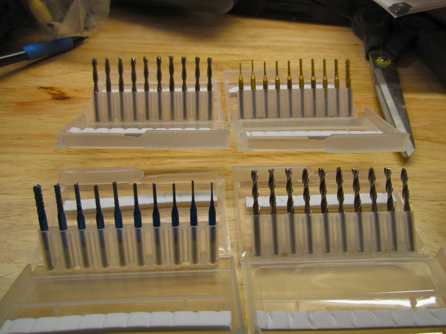
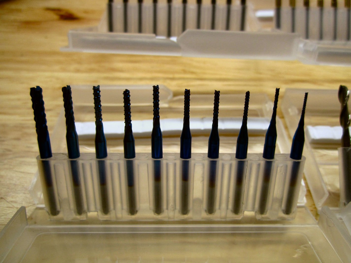
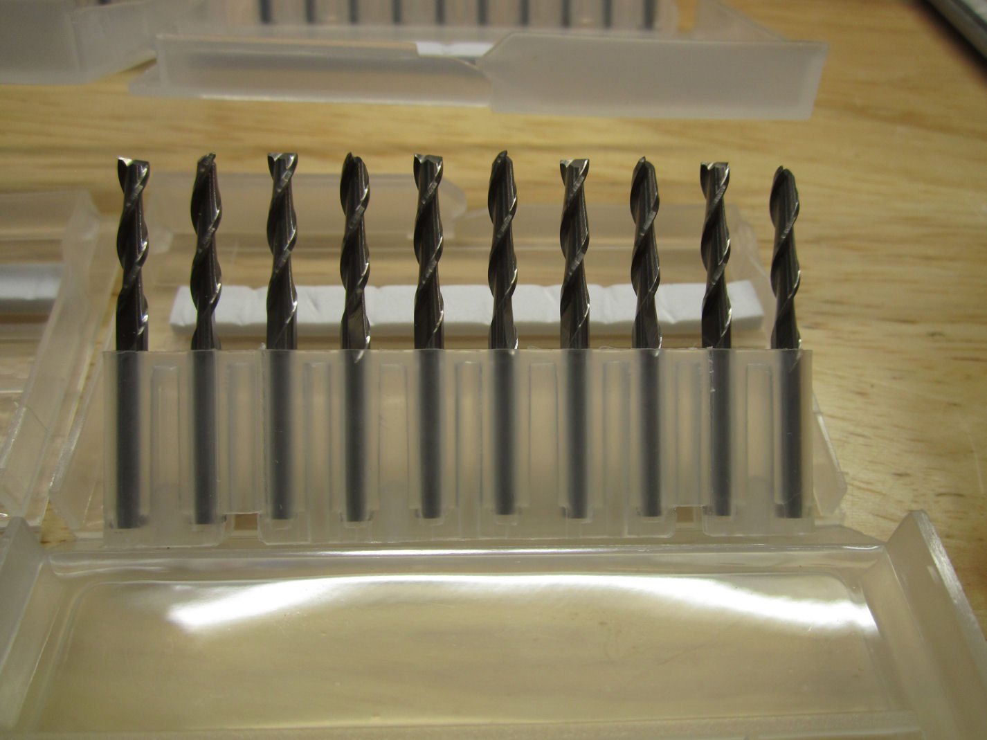
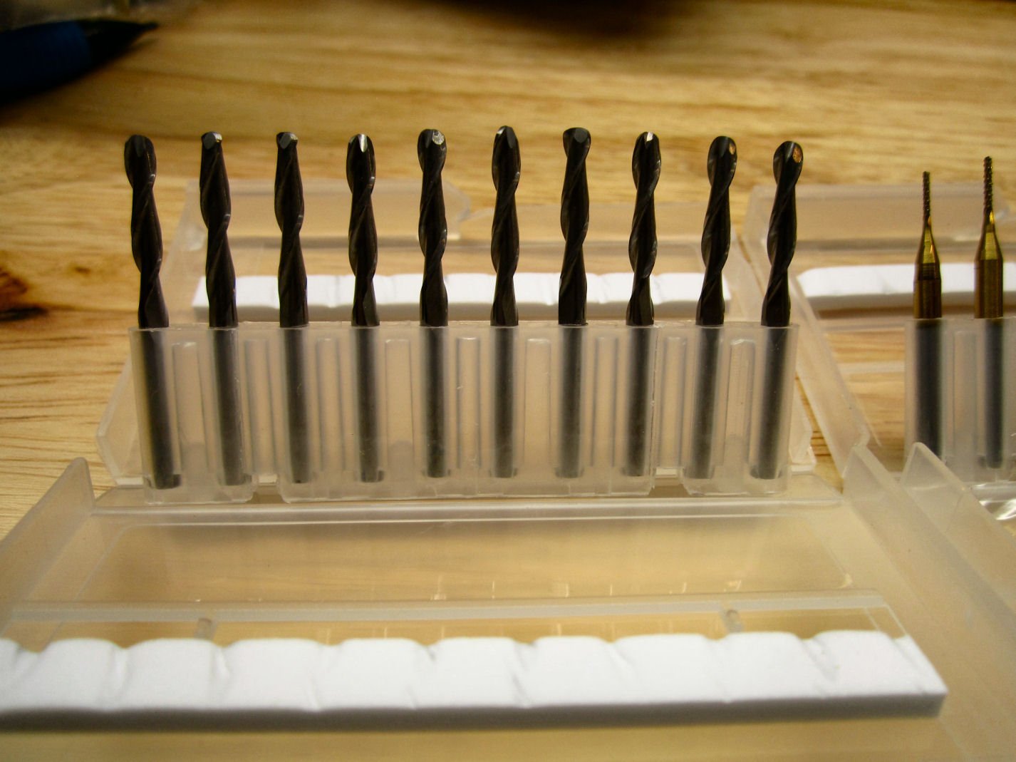
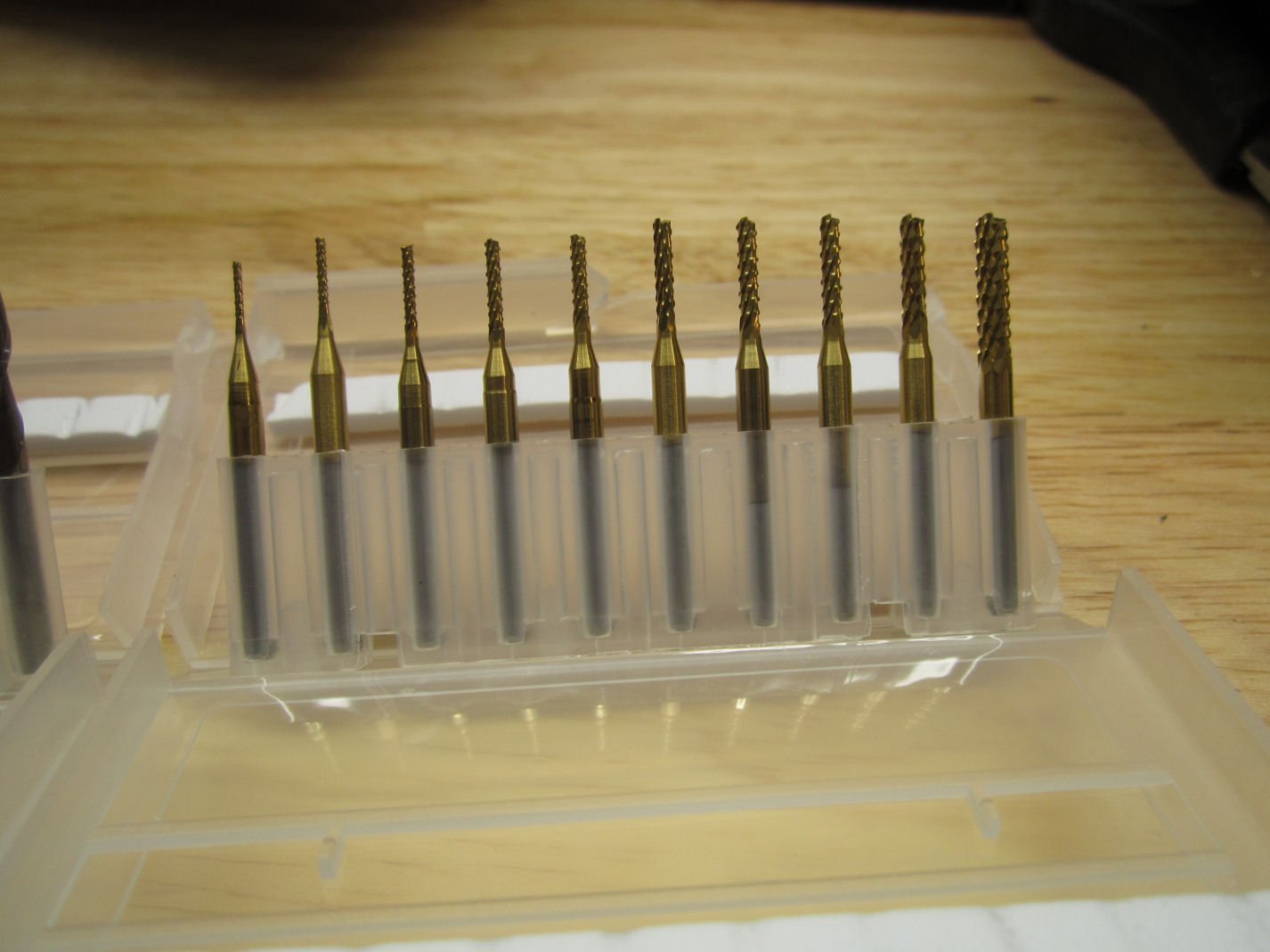
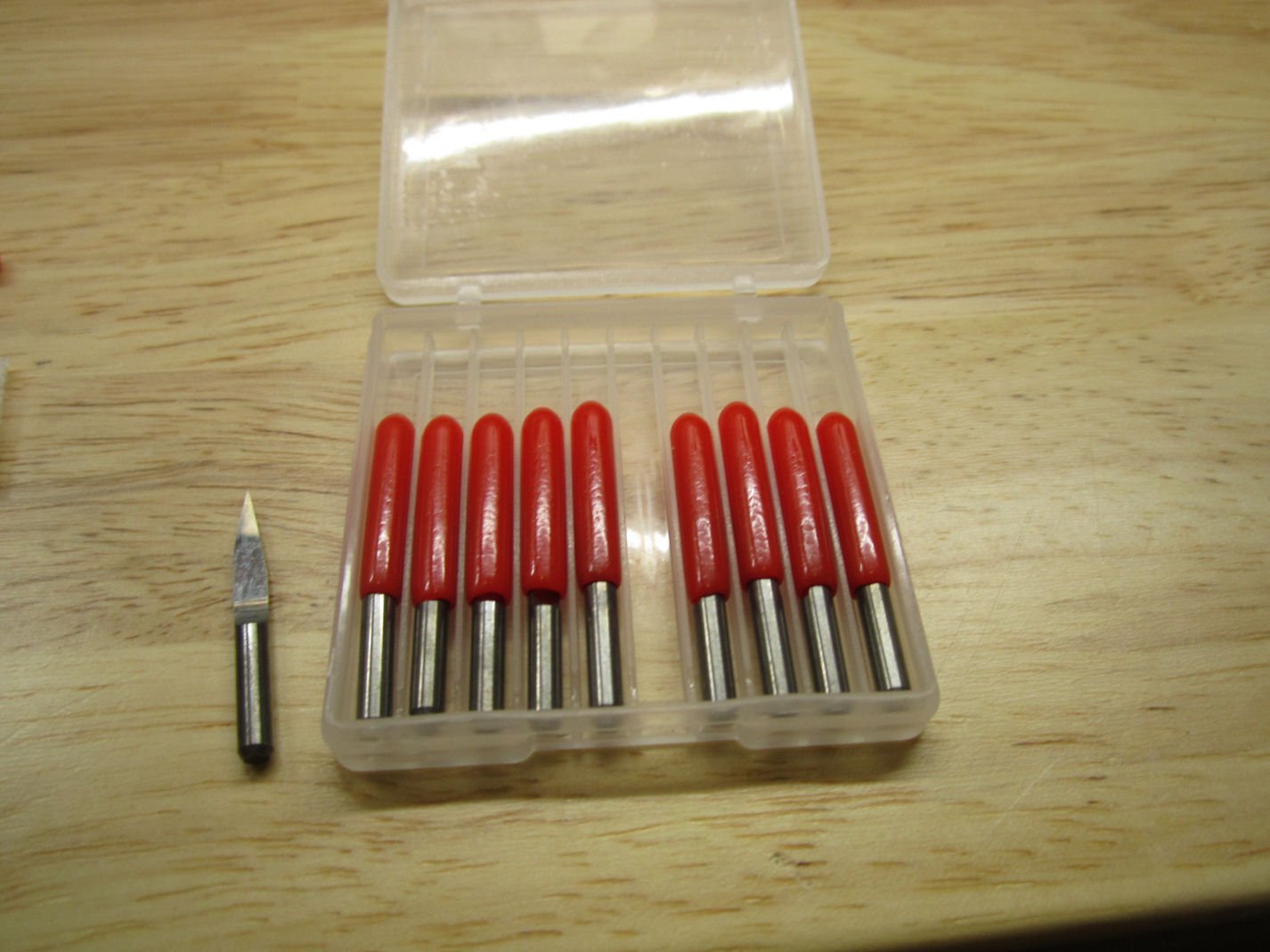
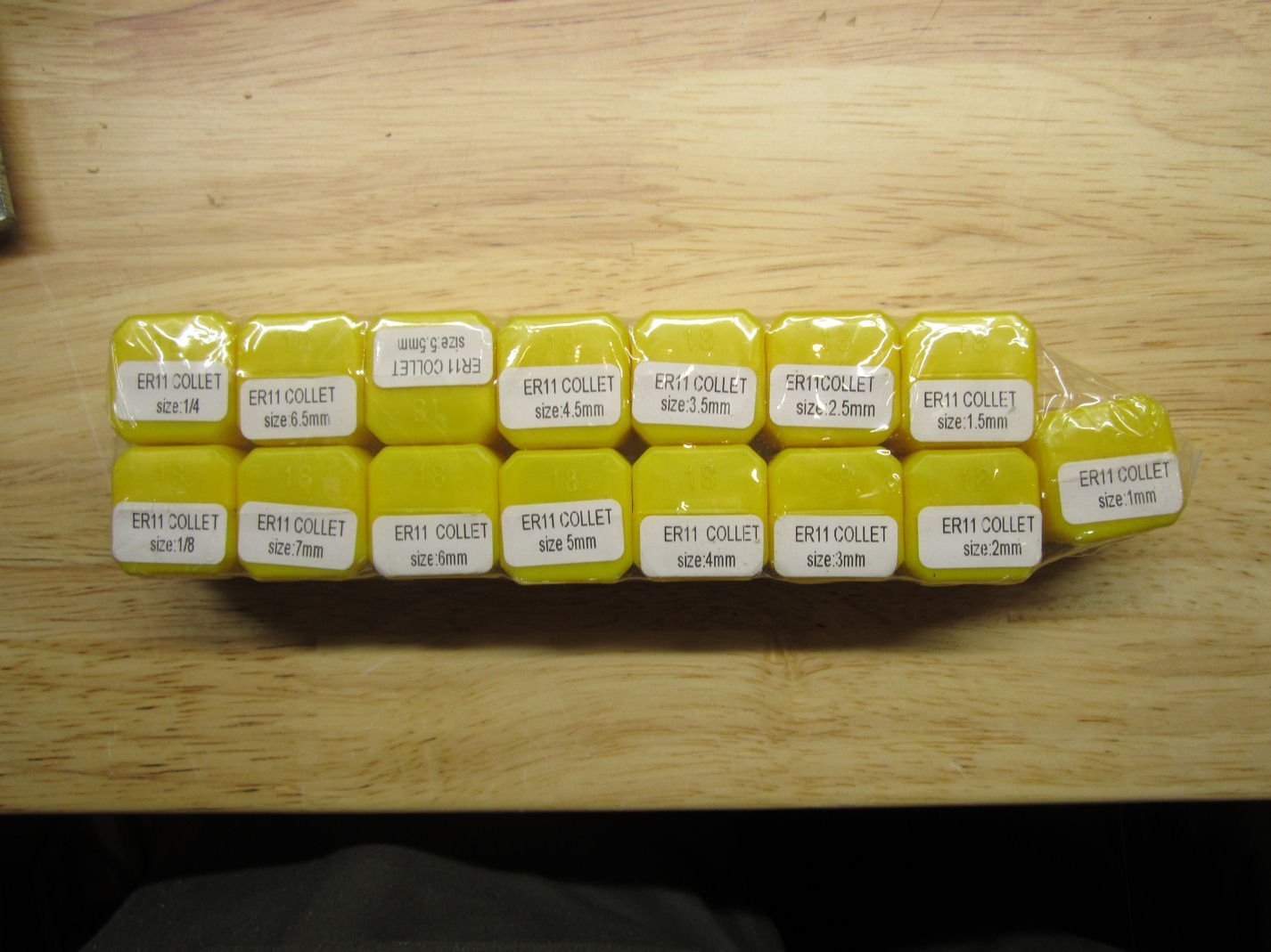
Part 003 The last layer holds the base of the machine. The bracket just up from the Y-Axis knob, is for the Y-Axis 0 position limit switch. This shows the underside of the base. At the top is the Y-Axis adjustment knob, and below it the Y-Axis limit switch mounting bracket. The cross piece at the bottom of the picture is drilled to accept a mounting bracket for a limit switch for the other end of the Y-Axis (not included). I hope SainSmart will be offering a kit with the brackets and switches needed for the X and Y-Axis limit switches soon! You can see the metal linear slide bearings, and metal feedscrew nut mount.. The feet are preinstalled, on these machines, so you can ignore that step in the instructions. At the bottom is the stepper motor. This also shows the 40mm X 40mm side rails (as opposed to the Prover’s 20mm X 40mm rails). The top and bottom cross pieces are 2mm thicker than those on the Prover. Here is a picture of the top of the base. You can see the cast aluminum table with the etched grid and 30 mounting holes for attaching the supplied clamps, or to be used to bolt down a work piece. The grid is also numbered in both X and Y directions. I don’t know what size the mounting holes are. I’m going to take one of the clamp bolts to the hardware store and find out. In addition to the router, I also, separately, bought an additional set of cutters, and a set of 15 collets. SainSmart sells a set of 40 various cutters and if you buy the 15 piece collet set, you get a discount bundle deal. I also bought an additional set of 20 degree cutter bits, not realizing that the router came with a set. Here are the cutters in the 40 piece set. These are a set of “Corn Cob” bits with SainSmart’s “Nano Blue” coating. The “Nano Blue” coating provides additional wear resistance, over an uncoated bit. The “Corn Cob” refers to the bit being studded to provide more cutting surfaces. These remove more material in each pass, but give a rougher surface finish. These are typically used for roughing cuts to remove the bulk of material from a large area. You then change to a finer finish bit and run another pass to cut the final fine details. This group is a standard set of uncoated HSS 2-flute flat bottom end mills. These are used for flat bottom cuts, vertical sided cuts, and can be used for drilling or plunge cuts. They are similar to regular metal working end mills, used in milling machines. These are uncoated round nose end mills. They are used the same way as the flat bottom ones, but leave a semi-circular bottom when cutting a slot. They are typically used for the finish cuts in 3D relief designs as they can cut smooth sloping cuts, and rounded bottom transitions. The last set in the 40 pack, is another set of “Corn Cob” bits, but with a gold colored coating. I don’t know the difference between this and the “Nano Blue” coating, other than it too offers wear protection. SainSmart does not really explain the properties of the various coatings they offer. The last set of cutters a 10 pack of their standard 20 “V” bits. These are used for engraving, and rough cuts. The 15 piece collet set should hold any bits I’m likely to need for this machine. Collets hold a cutter shank securely, but each collet holds a specific size shaft. They do not have much, if any, ability to hold a different size shaft. Explaining why would involve much more detail, than I want to get into, just take my word for it. These collets are inexpensive though, so buying a set is not a problem. Part 4 will be the start of assembling the router.
-
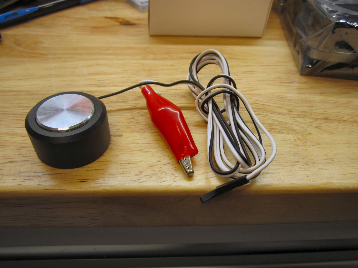
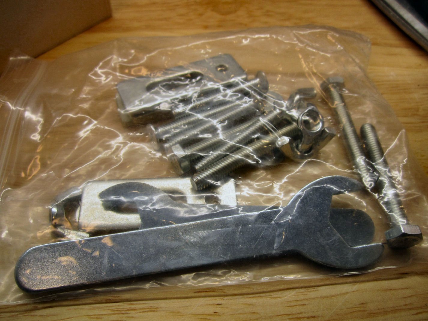
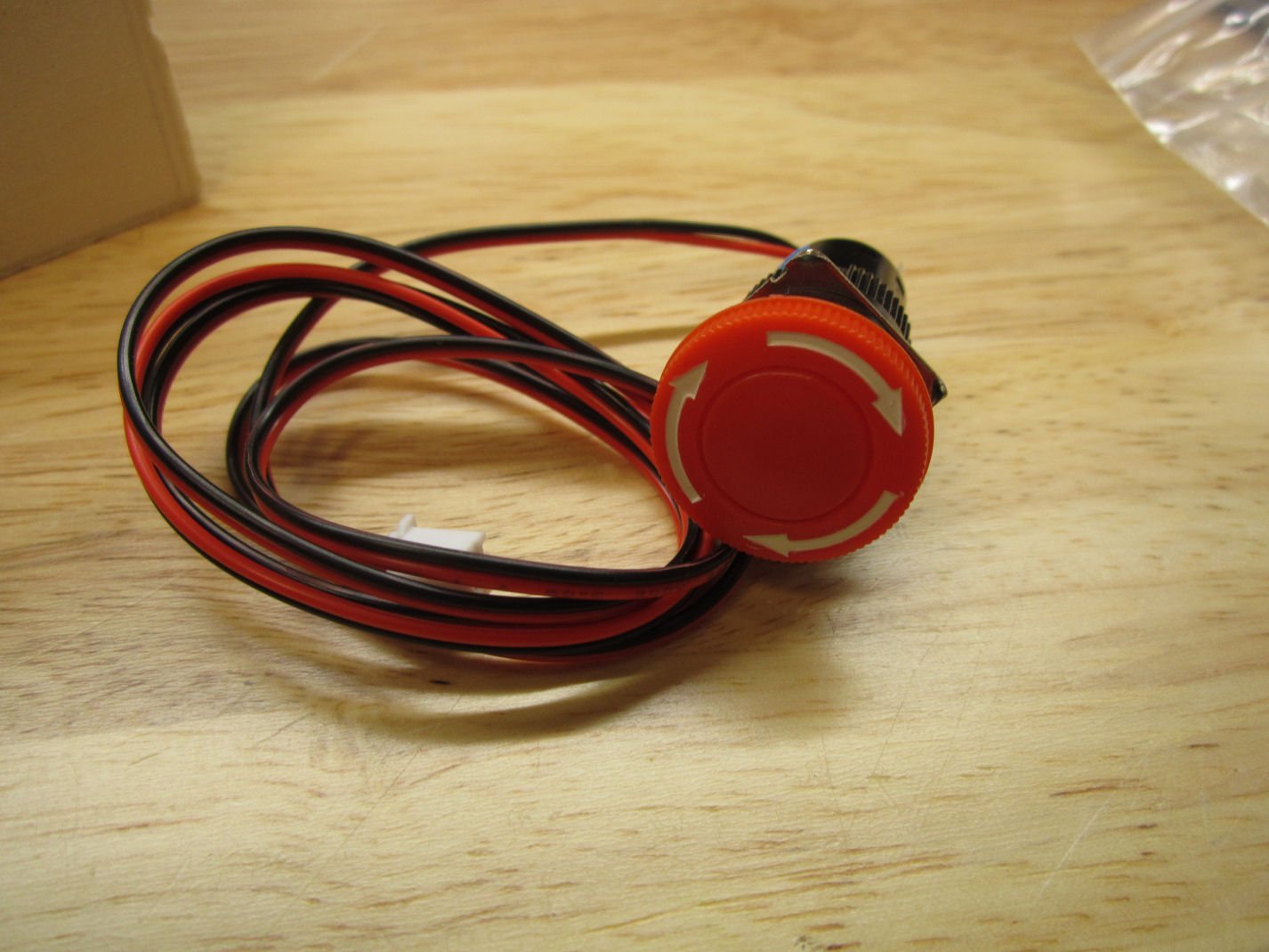
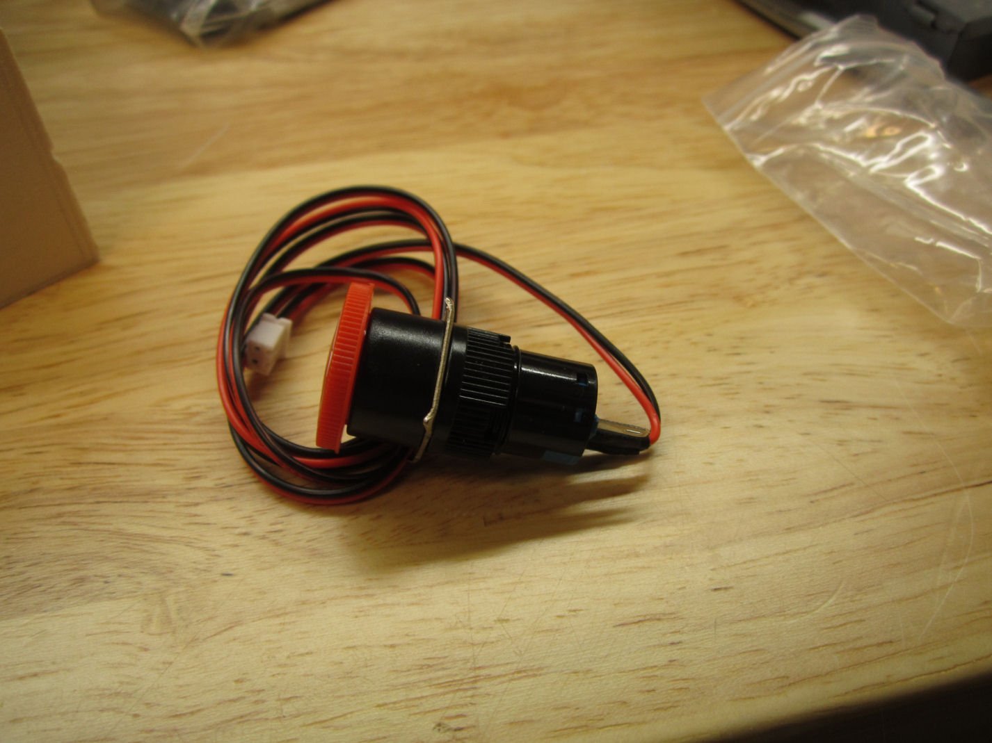
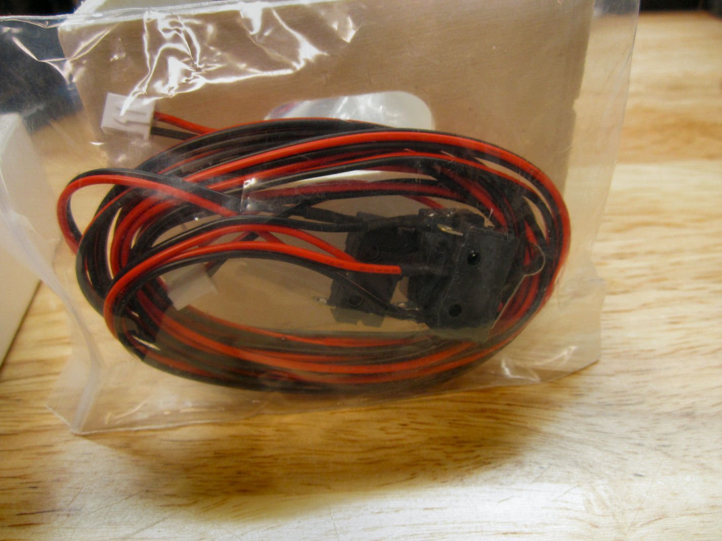
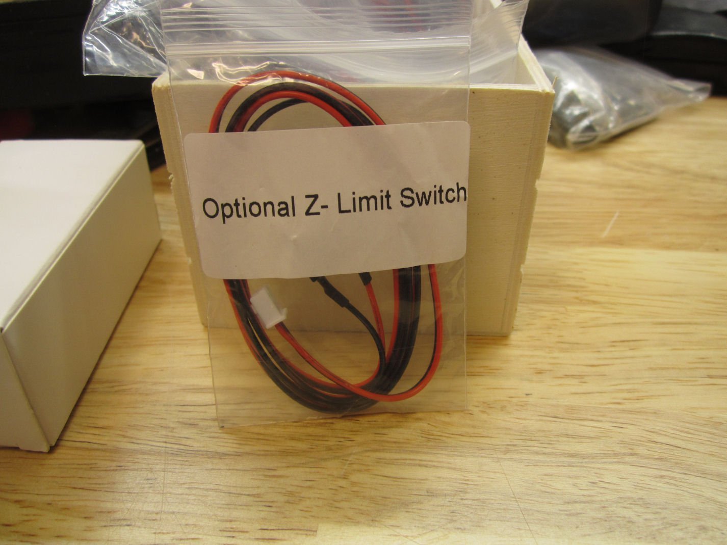
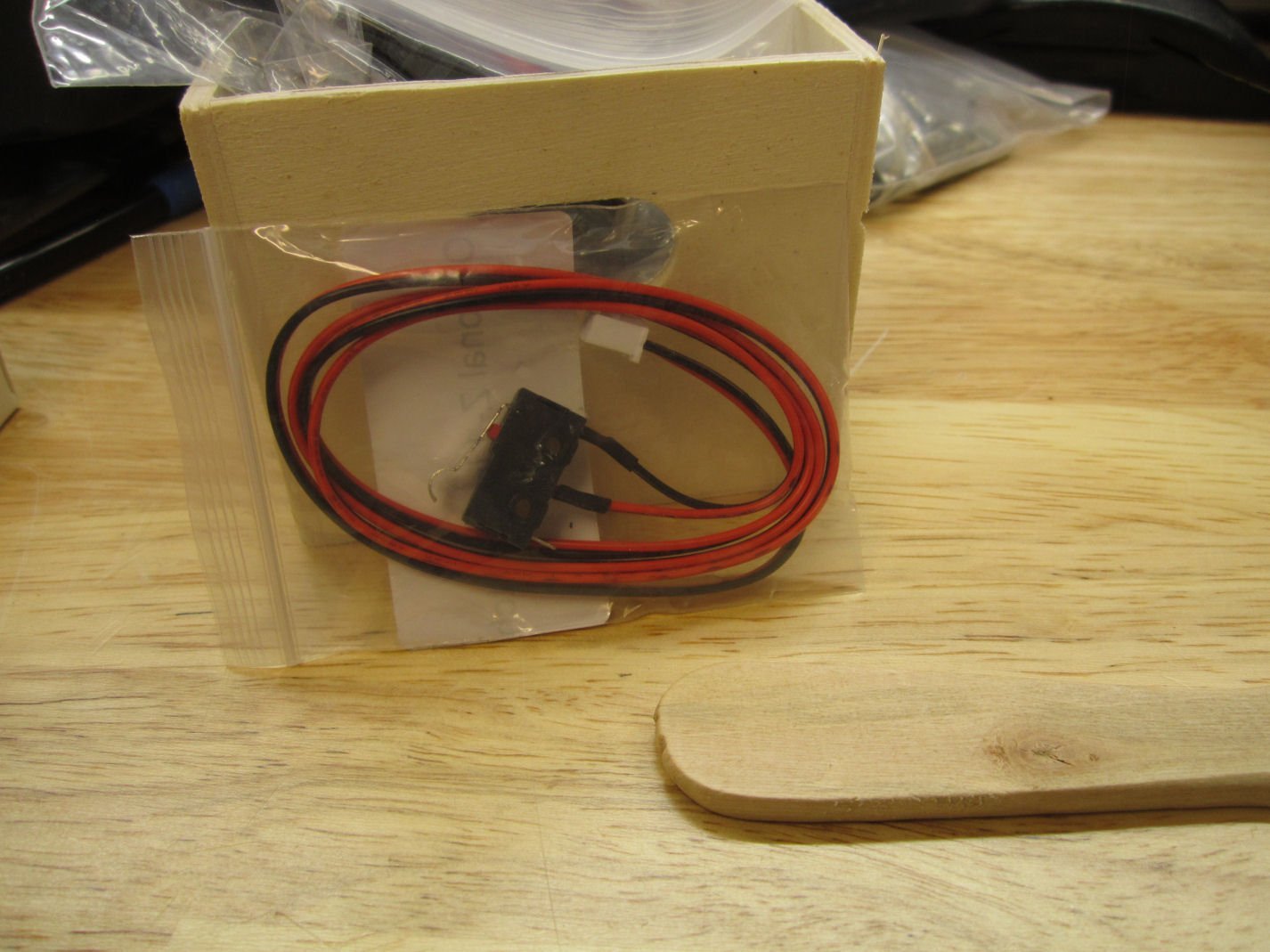
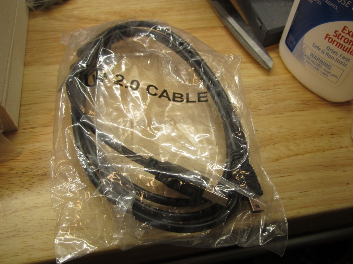
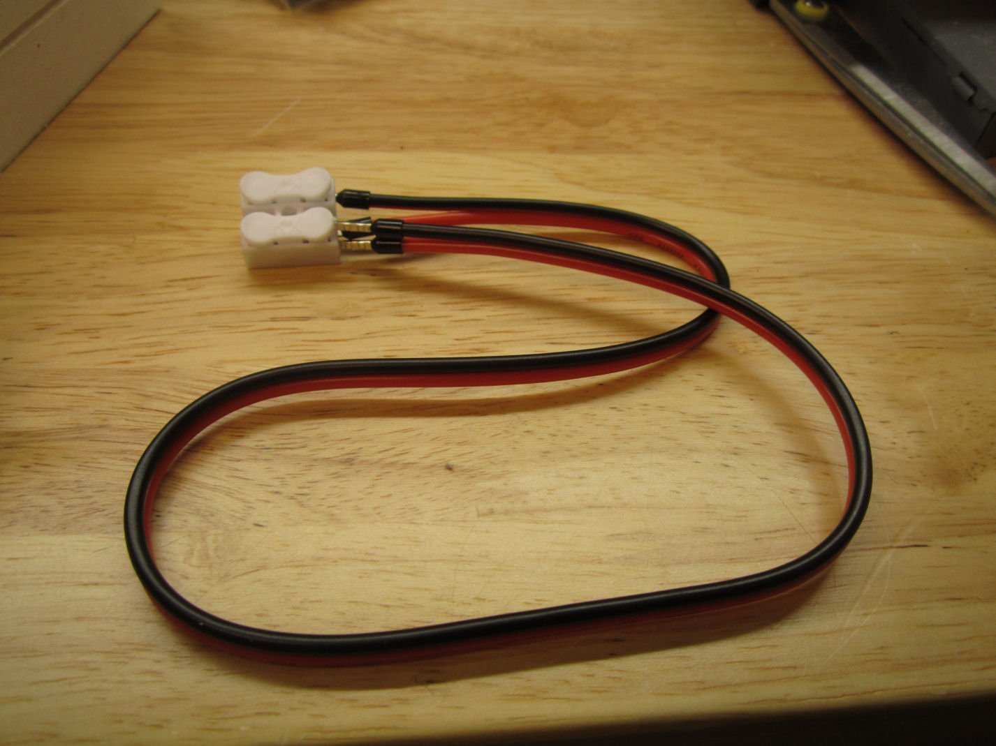
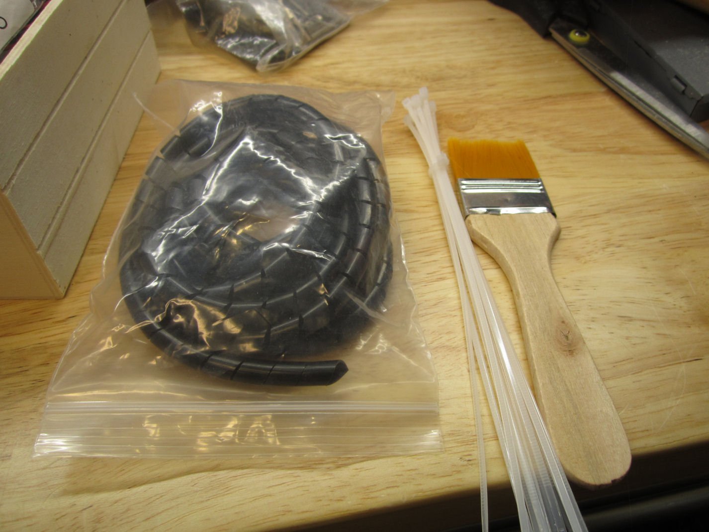
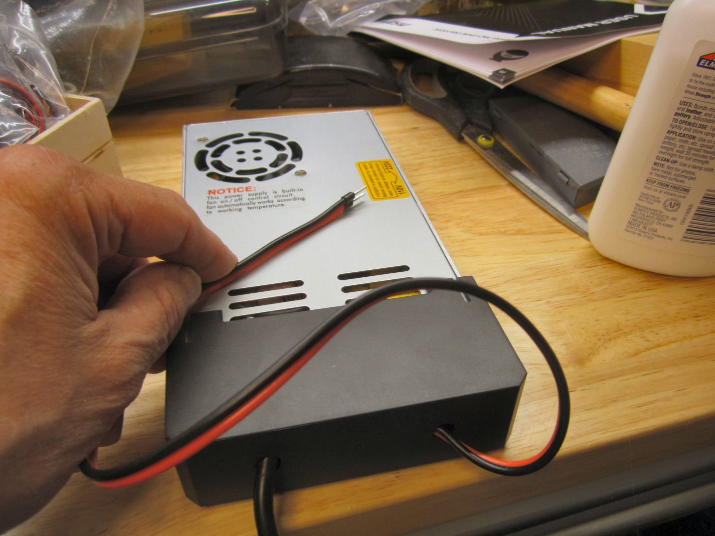
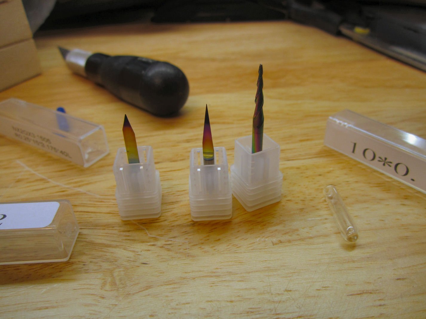
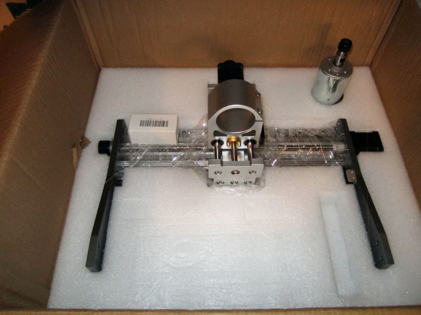
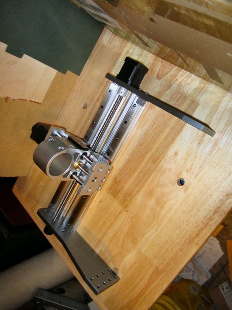
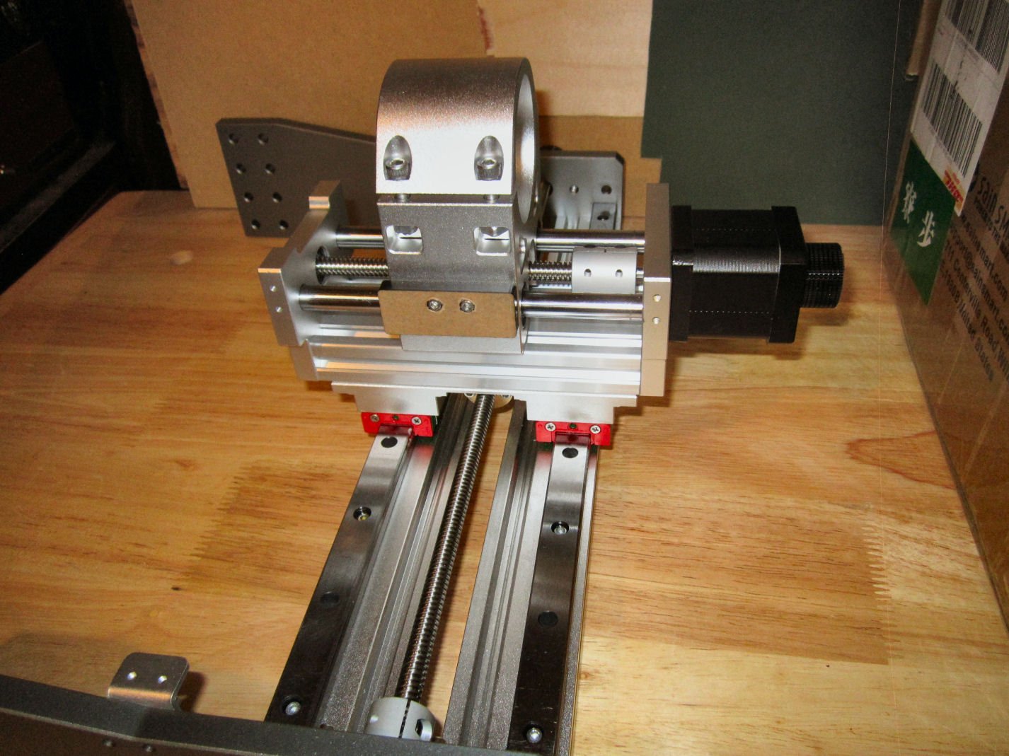
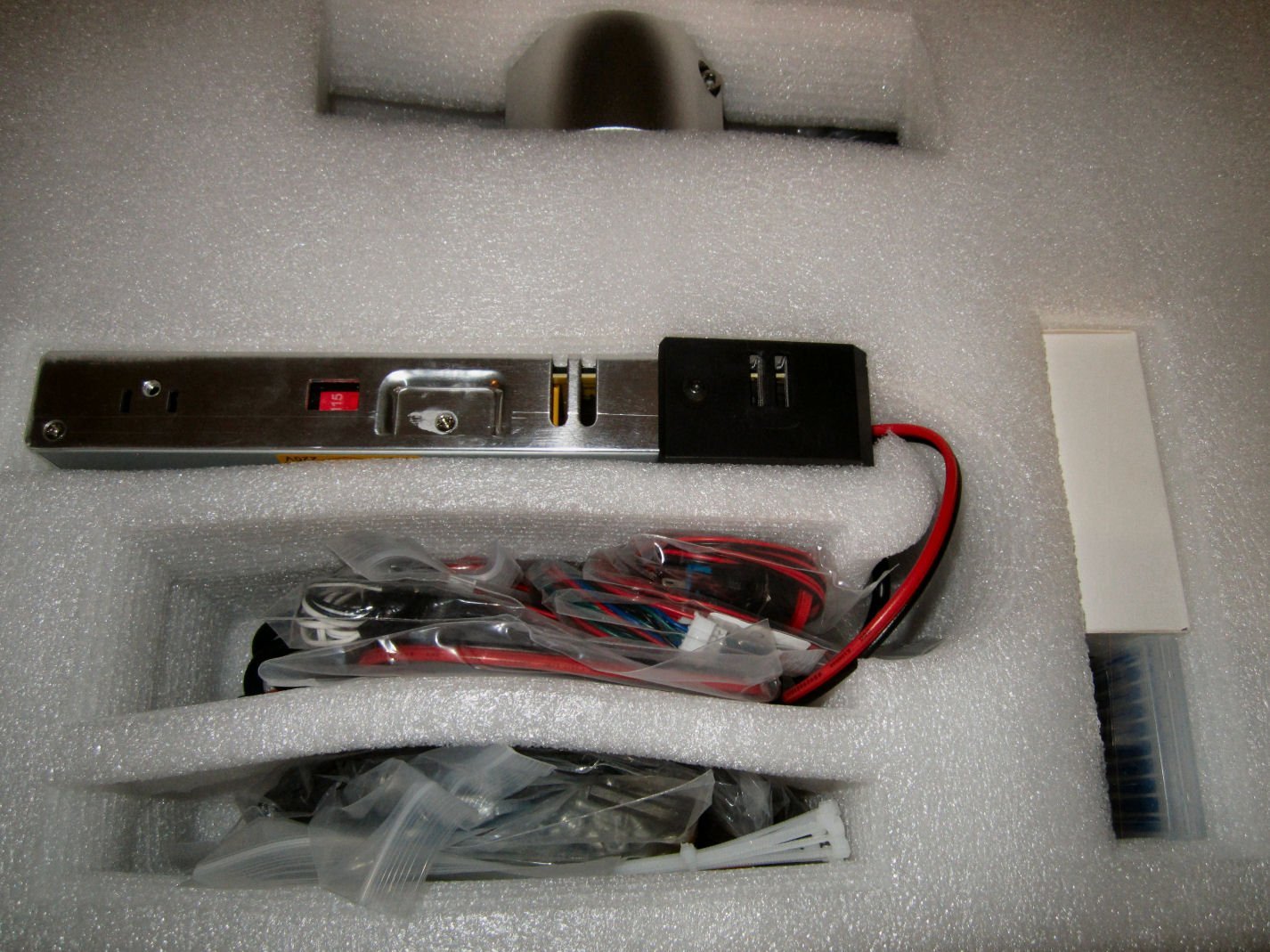
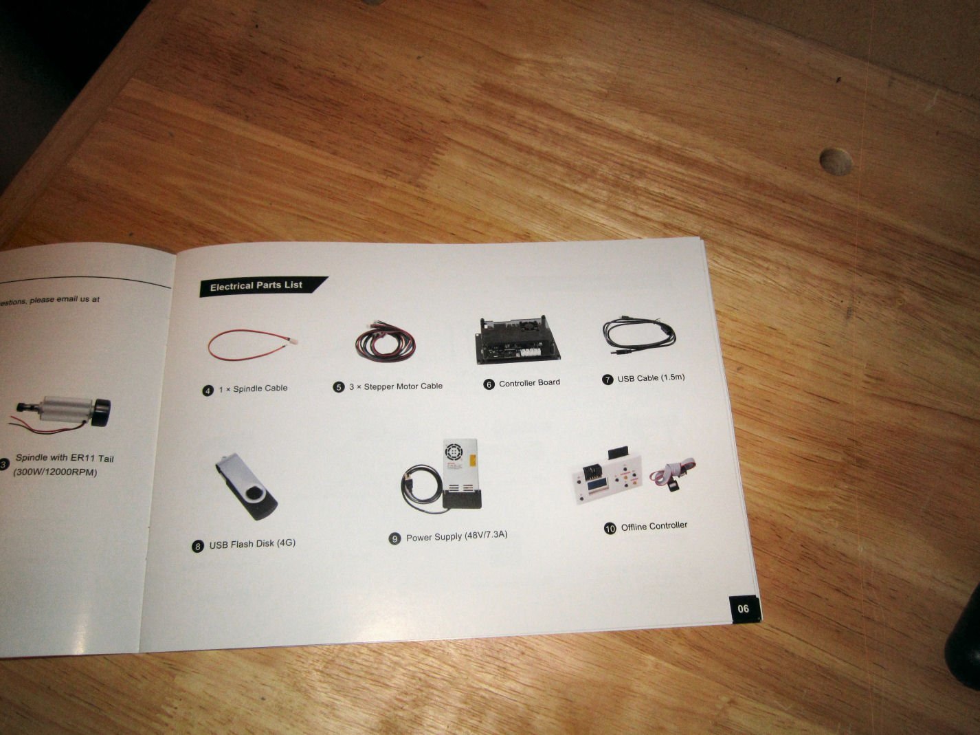
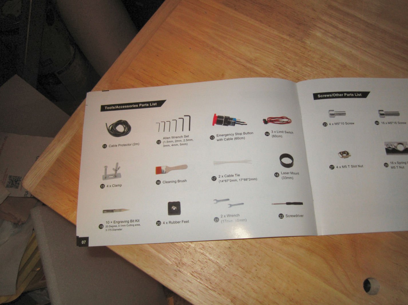
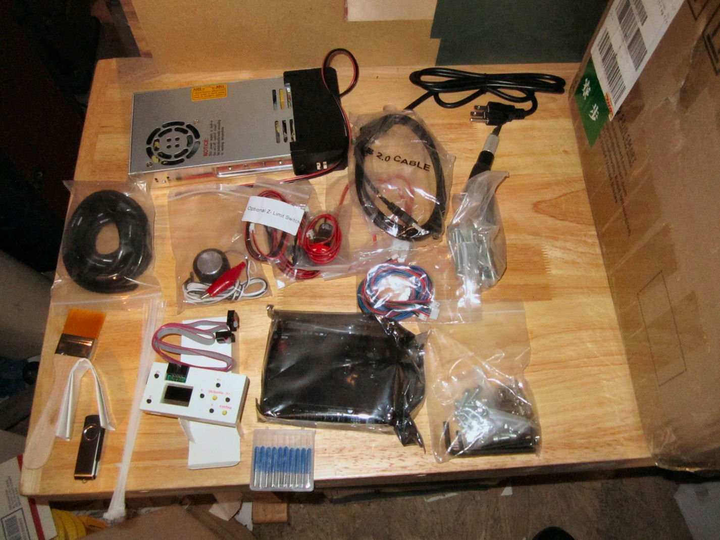
Part 002 Here is the Z-probe. Once you have loaded the cutting file and installed a cutter, you have to determine how far the end of the cutter is from the blank’s surface, so the machine knows what height to start the cut at. The probe is hooked to the machine, and the hardware can detect when a cutter touches the probe. You place this probe on top of the blanks, position the cutter over the probe, and then either manually lower the cuter until it touches the probe, or run a bit of code to lower the cutter automatically. When the bit contacts the probe, the machine then knows the exact height from the tip to the workpiece. The plug attaches to the controller board, and the alligator clip to the body of the cutter bit. After finishing with determining the height, the alligator clip is removed, and the probe moved away from the machine, naturally. The cable remains attached to the control board. The next bag contains the two wrenches needed to tighten the collet nut on the spindle, and the hardware for the four clamps to hold down the workpiece. This is the Emergency Stop Switch for the router. The instructions show this as already installed, but you have to install it. All this requires is removing the nut and washer, feeding it into the upright, installing the washer (Note: the points on the washer face the upright during installation), and screwing on the nut. The button is pressed to stop the machine, and then rotated clockwise to reset the button. BE careful installing the assembly, as the button will unscrew from the switch, if turned, counter clockwise,! Just screw it back on, if this happens. Yes, I had this happen. Next is the bag containing the three X,Y, and Z limit switches. As delivered there is only one for each Axis. These are used to “Home” the spindle to the 0,0,0 position (Spindle assembly to the far right for X, Table all the way forward for Y, and Spindle all the way up for Z. In other words the X=0 and Y=0 is at the upper right corner of the table). They also, of course, act as true limit switches for their respective end of each axis. The limits of travel for the other ends have to be manually set in software. Mounting holes are provided for brackets for additional X and Y Axis limit switches, but no hardware is included, so I’ll be contacting SainSmart about the availability of two more switches and brackets. See below about the additional Z Axis limit Switch. Also included as an optional switch for the Z-axis (Spindle Full Down). I installed it, Note that all these switches decrease the area that can be milled! I’ll go into it further in the Assembly sections later on. They also provide an USB cable to connect the machine, and the stand alone controller to your computer. This has the old “T” shaped small USB connector, so don’t lose it. For supplying power to the spindle, they use this patch cable that connects the power supply leads to the spindle motor wires. They supply a fairly long piece of spiral cable wrap to use in organizing all the cable runs. I made a few mistakes doing this, and could have used about an extra foot, but I did get them wrapped up. They give you a bundle of cable ties and a Chip Brush, also. The last piece in this group from the first layer, is the Spindle and Controller Board power supply. This unit does not have a power switch, so you have to either unplug it when not in use, or have a switch installed in the wall outlet, or use a power strip with a switch. The power supply has a built in cooling fan. Don’t panic, like I did, if the fan does not come on when you first plug it in. The fan is controlled internally to only run when the supply is hot enough to require cooling. The next layer of parts has the upper assembly with the X and Z Axis travelers, the 300 Watt spindle motor, and the three cutting bits that came as an extra with my pre-order. These bits will not be included with the machines ordered now. These are the three new style bits, that I suppose are designed for use with metal. They have a multi-chromatic color coating. The upper assembly is shown in these pictures. The spindle mount holds the larger 52mm diameter 600 Watt spindle motor. The Prover’s 60 Watt motor is 42mm. There was supposed to be a 42mm ring adapter to allow you to use one of their laser units, included, but it was missing from my box. I’ll contact SainSmart this week to see if they will send me a replacement ring. The spindle comes with a collet that holds a 1/8" cutter bit. Most of the cutters range in the 1/8" to 1/4" shank diameter. SainSmart sells other collets for these shanks This pictures shows the assembly from the bottom. At the top is the stepper motor for the Z-Axis, with the Z-Axis adjustment knob above it. The all-aluminum Spindle assembly runs on two linear bearings for X-Axis travel. To the left is the X-Axis feed adjustment knob, and to the right is the X-Axis stepper motor. Just down from the stepper motor is the bracket for the X-Axis 0 position limit switch. The left hand upright has mounting holes drill to accept a similar bracket (not included) for mounting a limit switch for the other end of the axis. The spindle up/down Z-Axis is also drilled for both switches, and an optional switch is included in the kit. The Z-Axis also has metal linear bearings, and feedscrew mount. The feedscrew mount for the X-Axis feedscrew is also metal. You can see the holes for the 16 mounting bolts at the base of the uprights. The Prover has 12 mounting bolts and a narrower base. This picture shows the X-Axis linear bearings, as well as the larger metal stepper motor coupling nut used for all three axis. The brown block on the side of the spindle assembly, is the contact surface for the upper and lower Z-Axis limit switch contacts. The un-boxing will continue in Part 3.
-
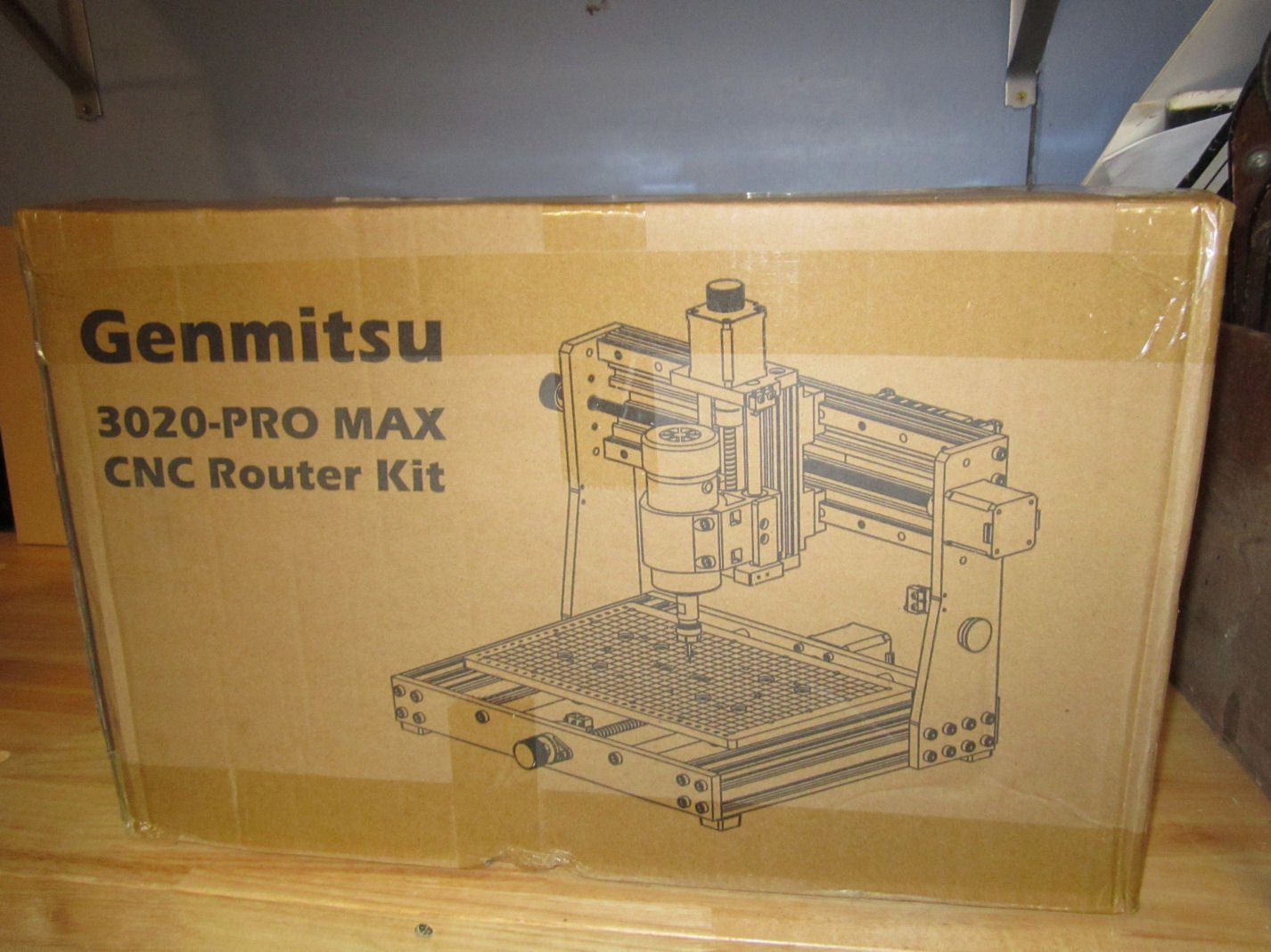
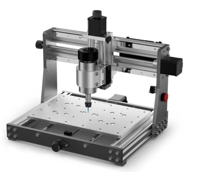
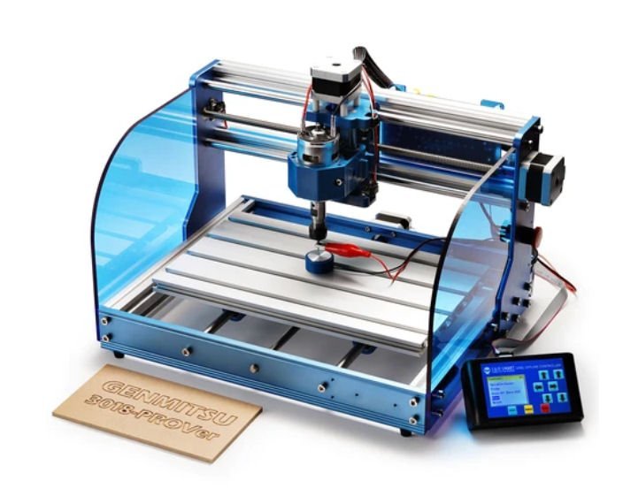
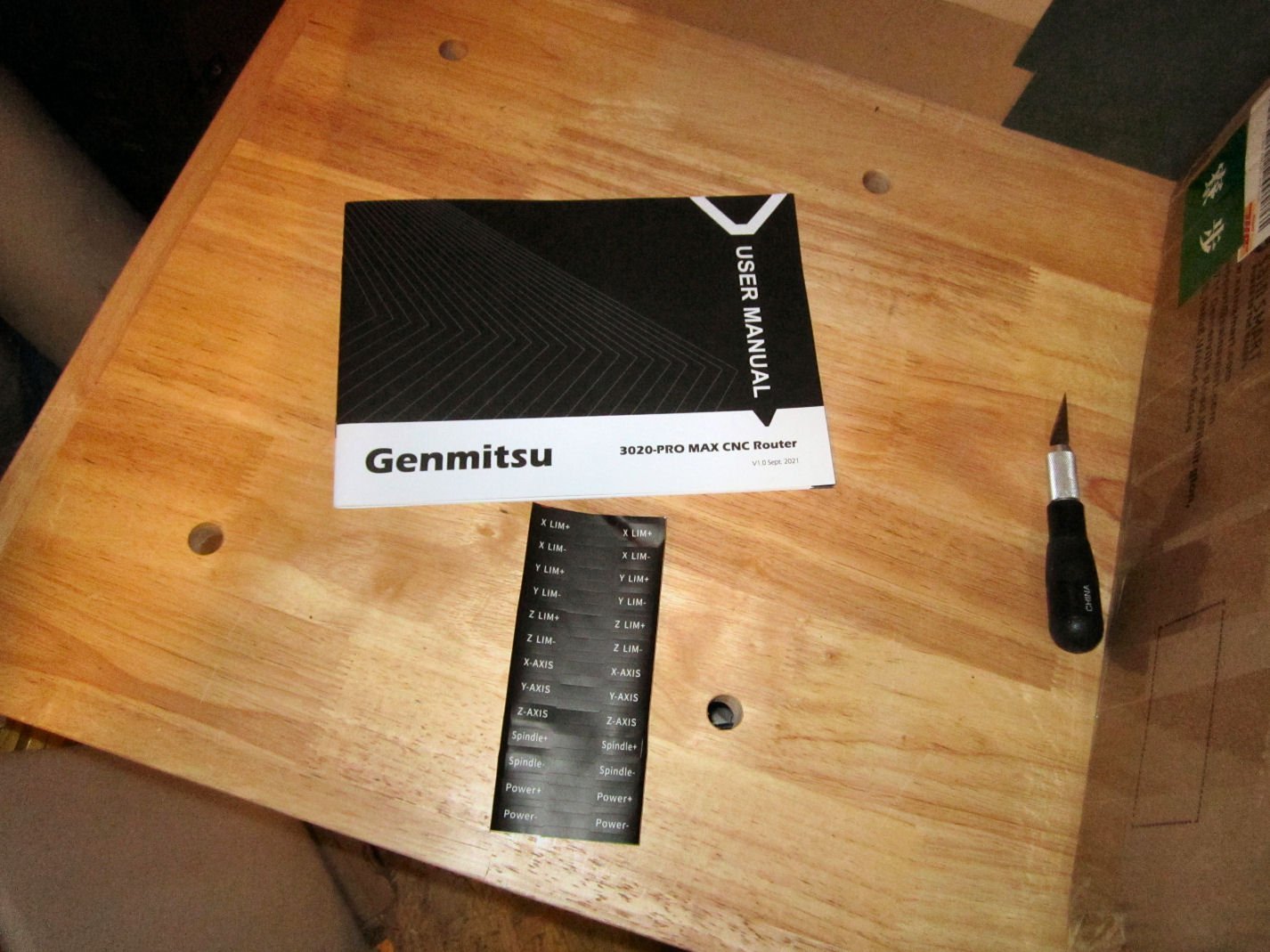
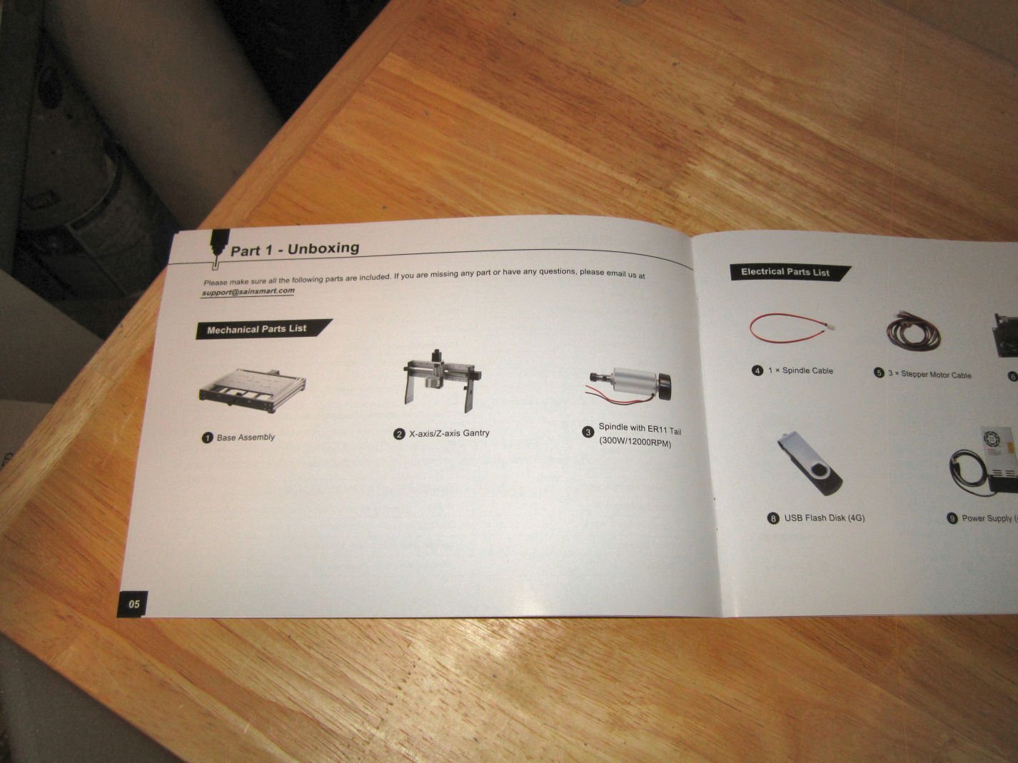
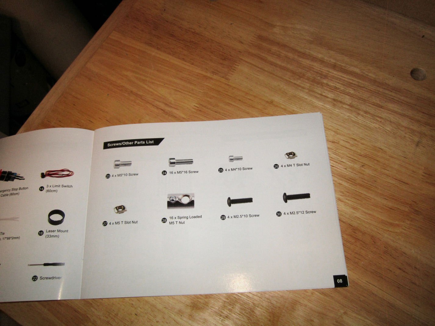
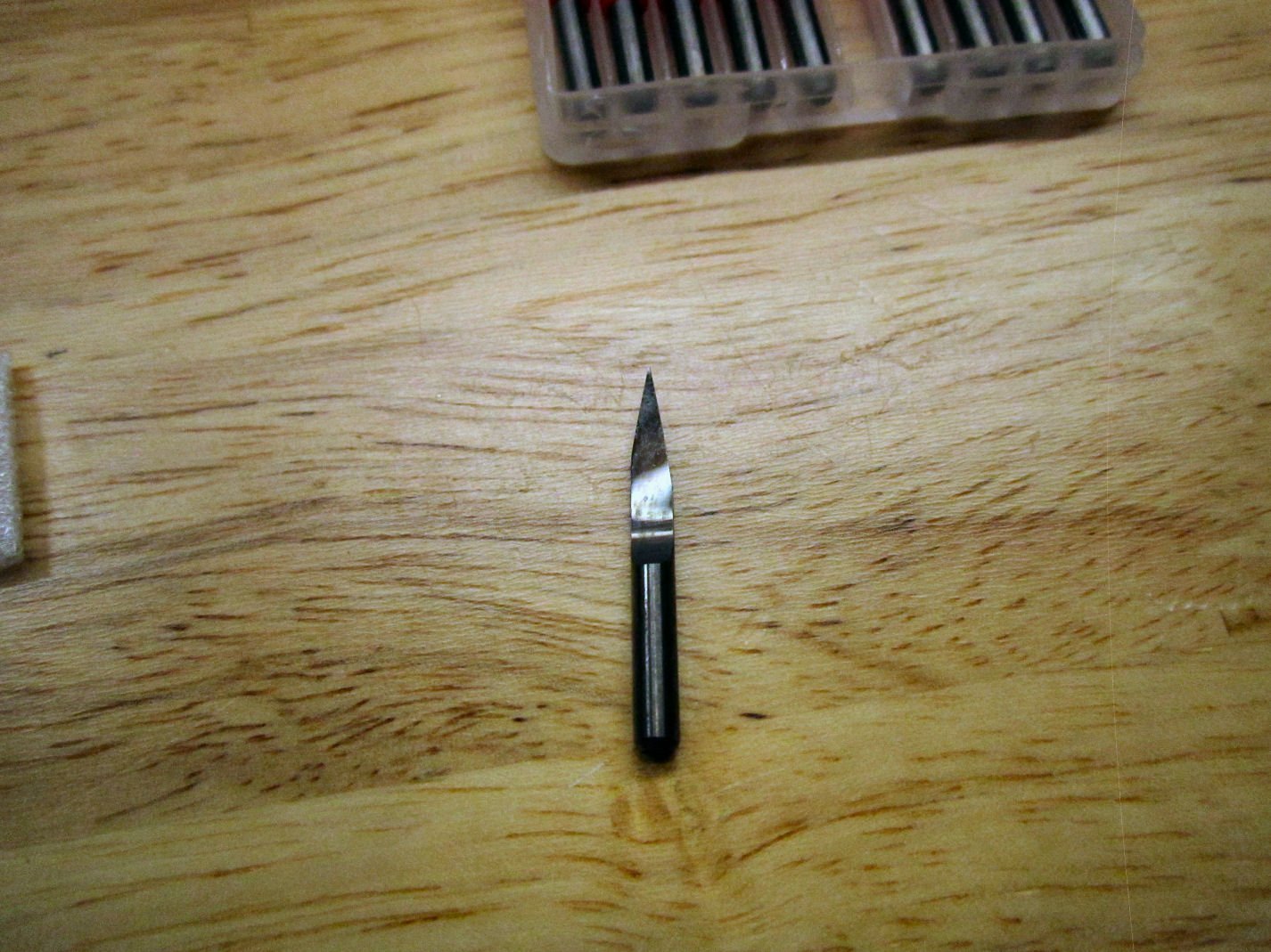
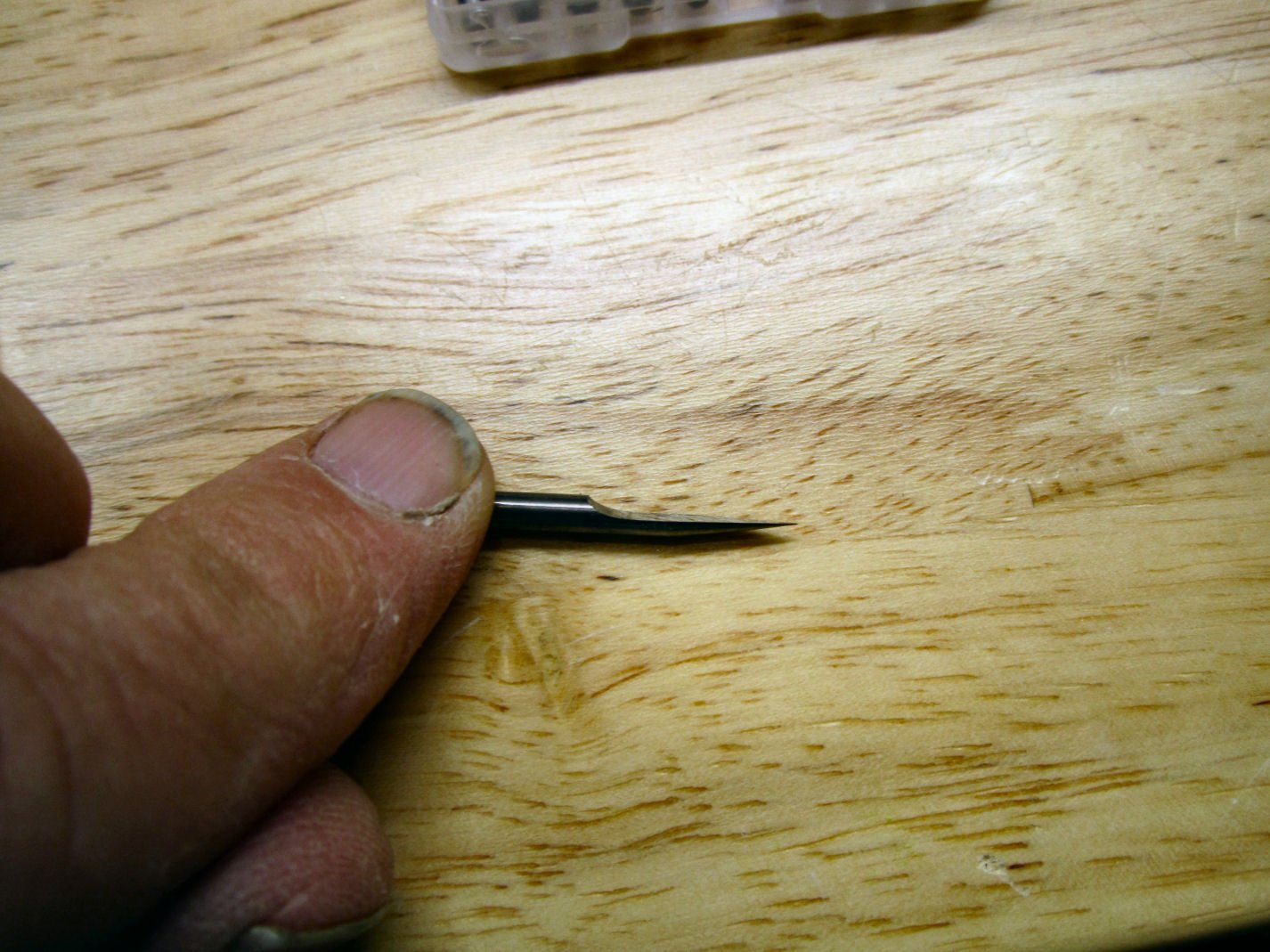
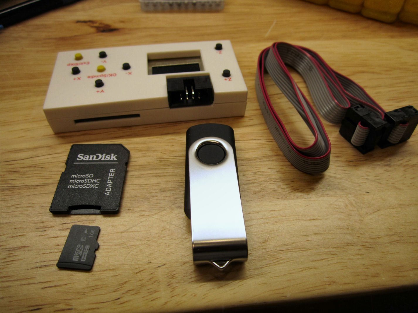
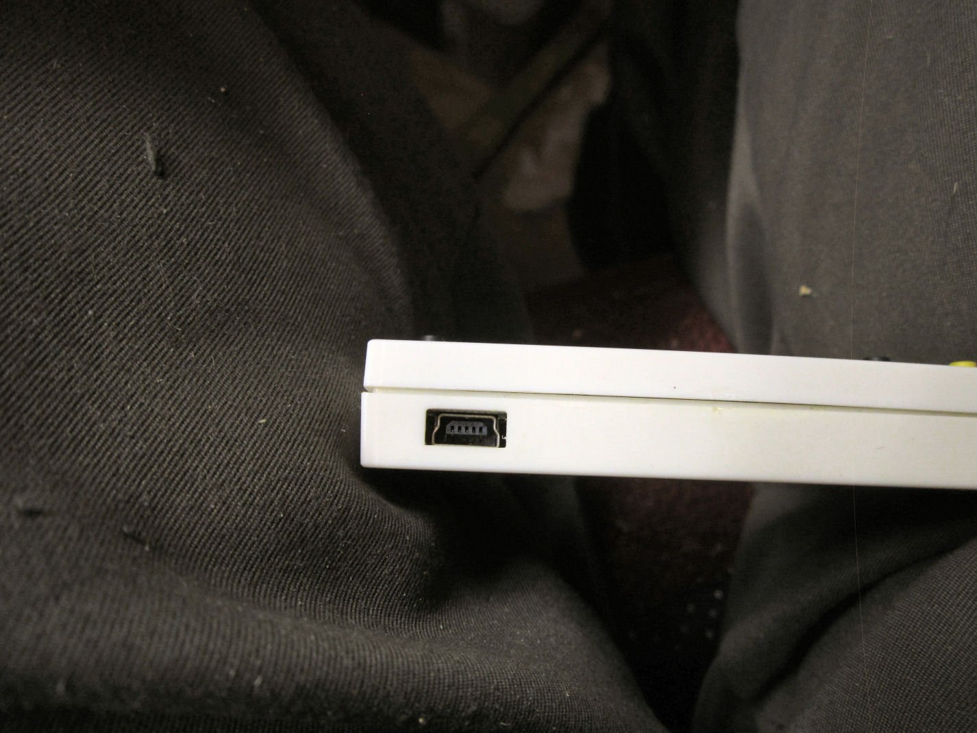
Part 001 This will be a three part un-boxing, with assembly to start in Part 4. I purchased a SainSmart Genmitsu 3020 CNC Router (300mm by 200mm table) during their Pre-order sale, and it arrived the other day. This will be a build log of the unboxing, and assembly of the router. SainSmart has a great reputation in the small CNC router community. The 3018 Prover is the best value among the 3018 machines, even over their lower cost 3018 Pro machines. Most of the 3018 machines out there have Bakelite front and back base pieces, as well as the uprights. The Prover has an all aluminum frame. I had been looking at their 3018 Prover machine (300mm by 180mm table), but had wanted to do some immediate upgrades to it. The cost of the upgrades would have made it more expensive than this new model they just released, and would still have been less sturdily constructed. The 3018 has one option that the 3020 may not have, though time will tell. The 3018 has an extension kit available to make it a 300mm by 400mm table machine. I was planning to install the extension on my a 3018. The table with the extension, though is made from two sections of extruded aluminum set on a MDF base. The table thus has more give than I would want for a precision machine. It would be perfectly good for most of my needs, but the 3020 has a stronger mechanism. The 3020 costs about $150 to $200 dollars more than the 3018 (depending on sale prices), so for lighter jobs you can decide. 3020 CNC 3018 Prover The 3020 has several improvements over the 3018: 1. The side pieces on the base assembly are 40mmX40mm extrusions, rather than the Prover’s 20X20. 2. The uprights are 2mm thicker and have a wider base with 16 screws attachment bolts. The Prover has 12 bolts. 3. The linear bearings under the bed as well as the assembly holding the feedscrew are metal on the 3020, on the 3018 they are plastic. The rods the bearings slide on are 12mm on the 3020 and 10mm on the Prover. 4. The X axis slides (mounted at the top of the upright) are linear slides mounted on 20X40 extrusions on the 3020, and 10mm round linear bearings on 10mm rods on the Prover. The linear bearings are thus supported their entire length on the 3020, while the rods are the only support on the Prover. The stiffeners for the 3018 are 20x20 extrusions, giving less stiffness than the larger ones on the 3020. 5. The 3020 has stronger servos than the 3018. 6. A nice feature on the 3020, is that all the feedscrews have knobs for manually turning the screws. On the 3018, you have to try to turn them by grabbing the screw itself. 7. The 3020 has SainSmart’s 300 watt motor, rather than the 3018’s 60 watt one. 8. The 3020 has an aluminum motor mount, the 3018 a 3D printed plastic one. The last two features alone are worth the extra cost, to add an aluminum motor mount and a 300 watt motor to the 3018, costs more than the additional price of the 3020! One down side of the aluminum plate on the 3020, is that it is a cast plate. Cast aluminum plate is more brittle than an extruded plate, so some care has to be made not to overly tighten any clamps or hold down screws when clamping work to the plate. Extruded aluminum plates are seldom flat, though, so that is probably why they went this route. Neither machine will cut to milling machine tolerances, but should do well for most any job we would need. The 3018 Prover comes with a little better off-line controller. Now to the un-boxing. I will say that it is well packed. When it was delivered the delivery guy needed a signature. Rather than letting me grab the box and set it down, he plopped the side of the box down on the pointed upright on my porch! It punched a hole in the side, but the surrounding foam protected the contents! Another hole in a different location on the box, as delivered, didn’t cause any damage either. It arrived in a good size box, that filled both arms as I was carrying it. The first thing seen when the box is opened, is a instructions/assembly manual, and a card of self-adhesive wiring labels. The first layer of packing holds most of the small parts and part bags, and there are a lot of them. The manual is a nice glossy paper item, with a parts list, the instructions for assembling the router, and installing the included free software. The software is usable, but definitely entry level. In the instructions they have a step for installing the rubber feet, but they come already installed. Here is a picture of everything in that first layer of stuff. They include a set of 10, 20 degree engraving/carving bits. They have rubber sleeves on the cutting tips, to both protect the edges, and protect your fingers from those same edges. These things are sharp! You leave the sleeve on when installing the bits, and then remove the sleeve right before starting the cuts. These bits are what is called in the machining industry “D” bits. The cross section of the cutting area is D shaped. Think grinding ½ of a round bar, leaving a half round shape. Next is the off-line controller box, with a cable, a slot for an SD card for loading the cutting files, a SD card for that use, a USB cable slot, and a connection for the controller cable to the machine. Also shown is the thumb drive with the software for the design and cutting programs, as well as a few simple designs to cut with.

-
I read that copper plating the fittings will seal them. Also some flow thru ventalation in the display case helps. Completely sealing the model accelerates the problem.
-
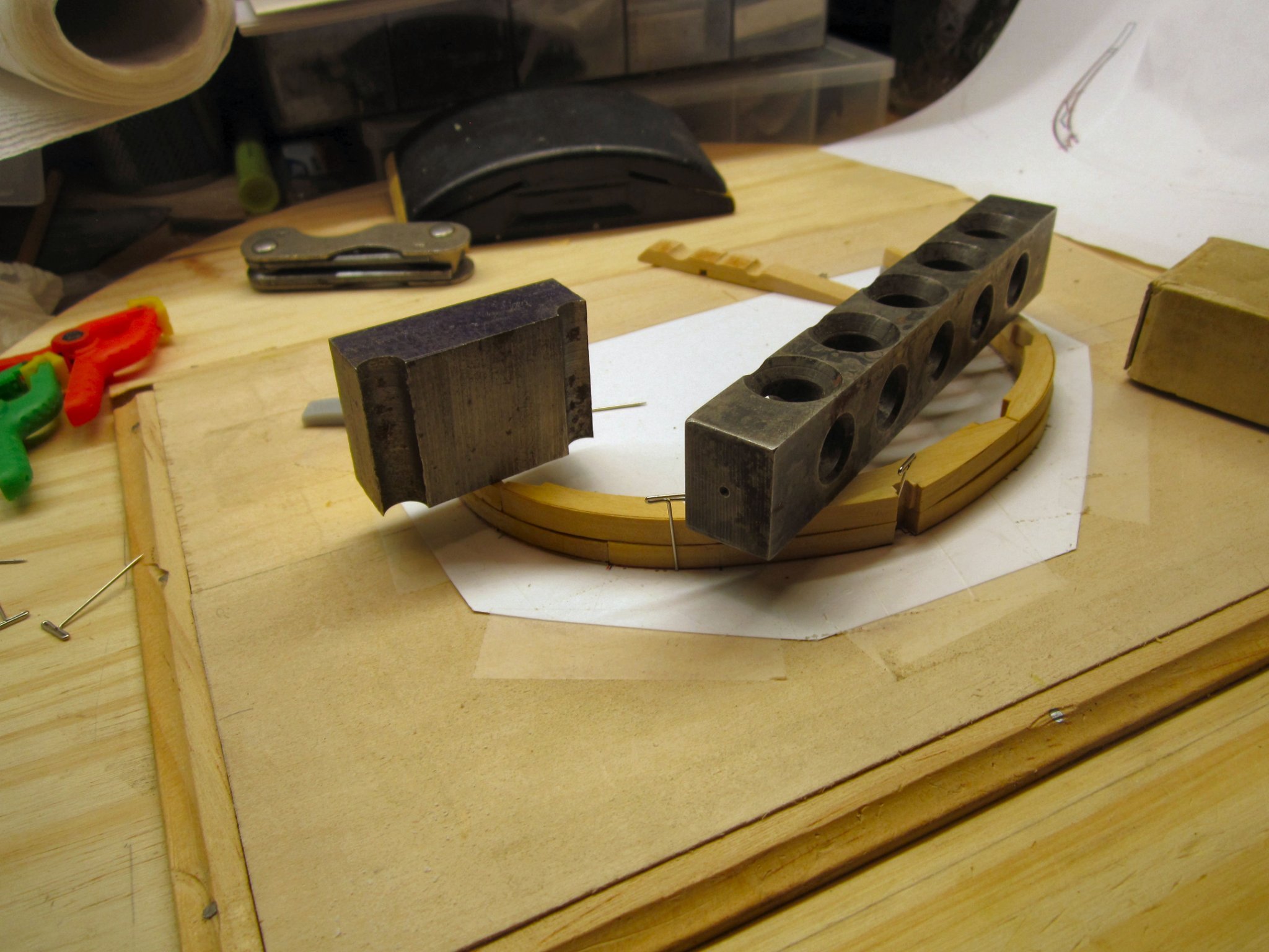
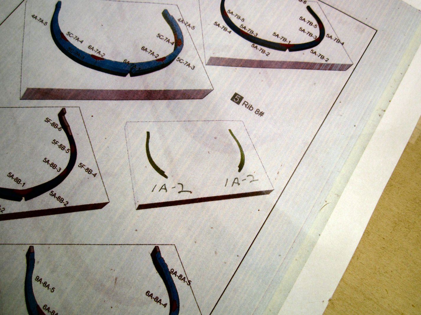
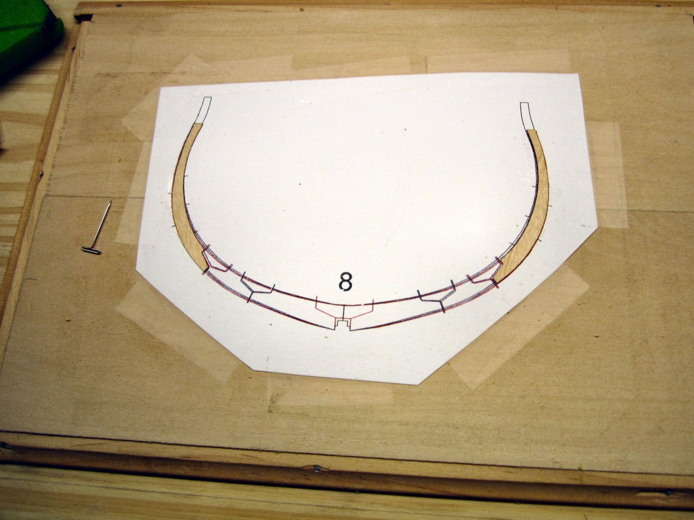
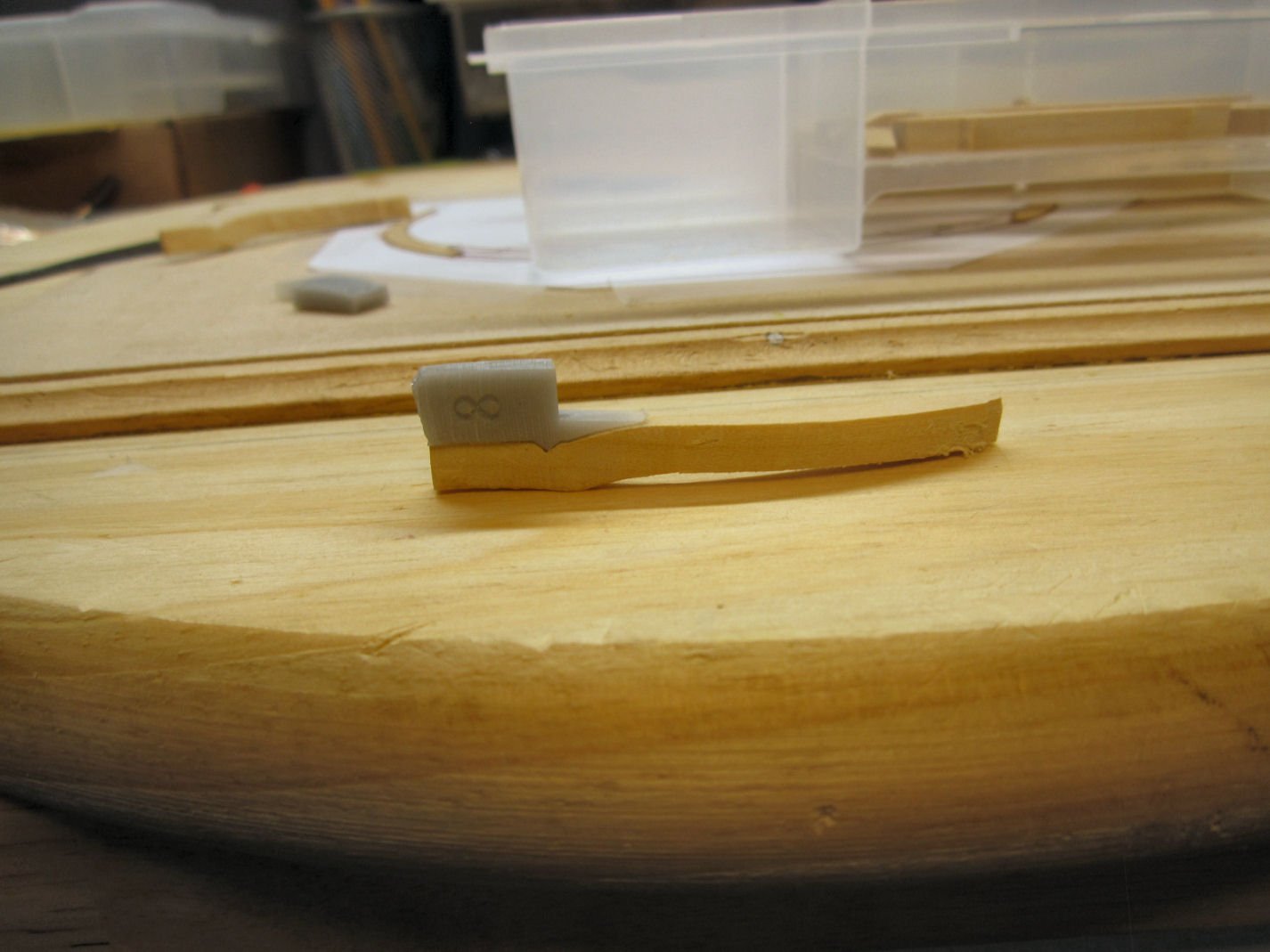
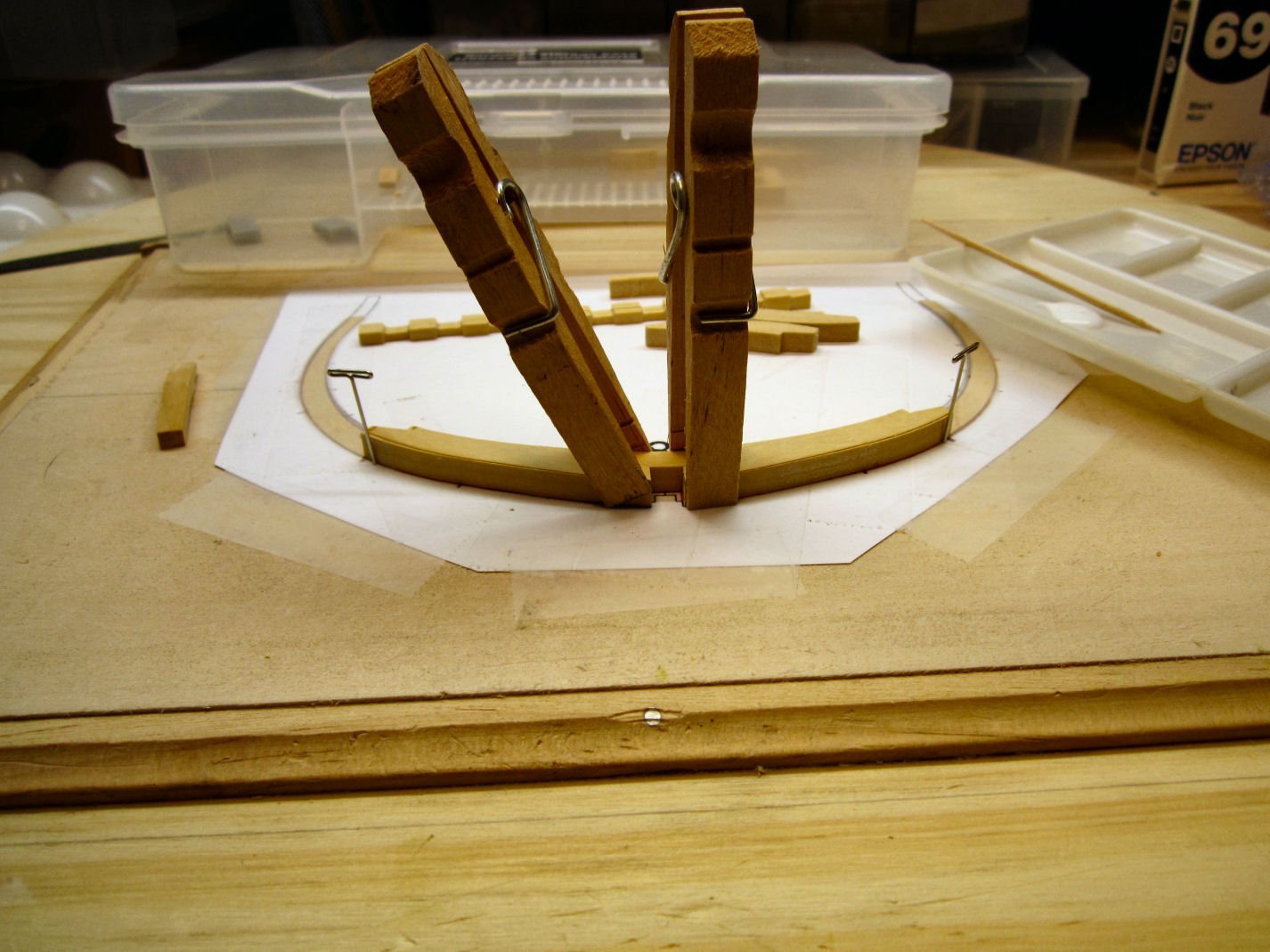
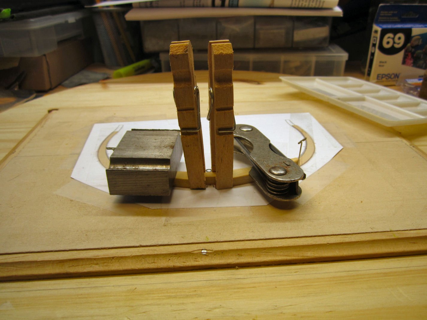
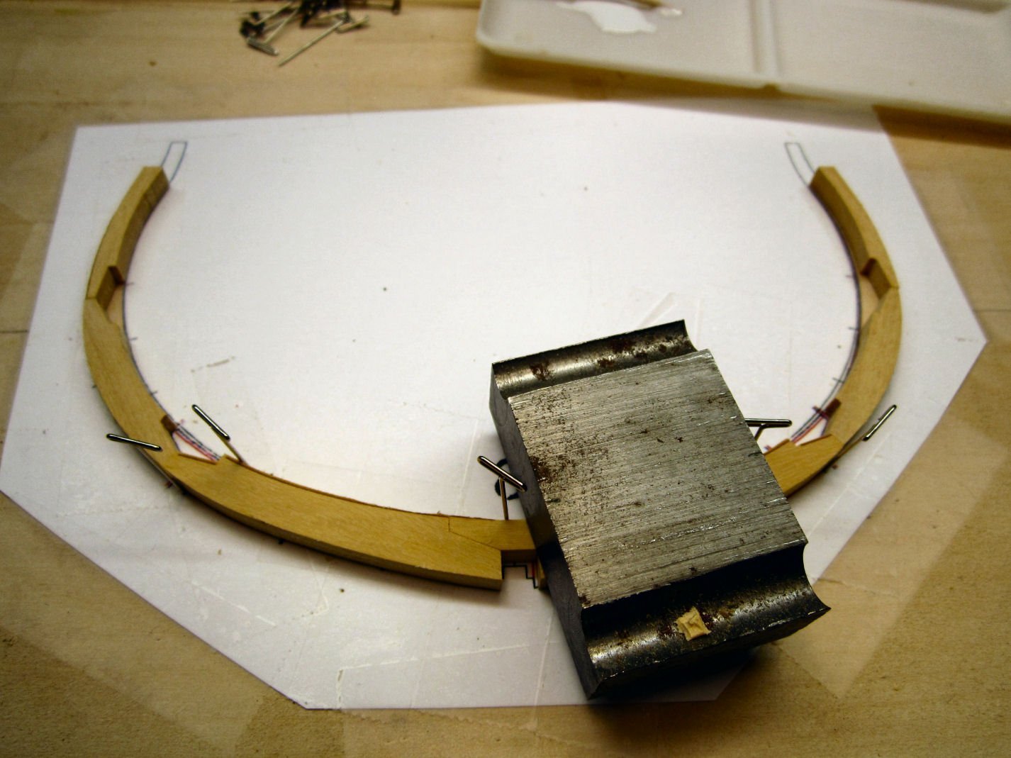
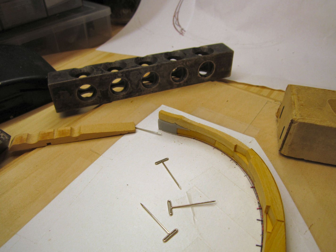
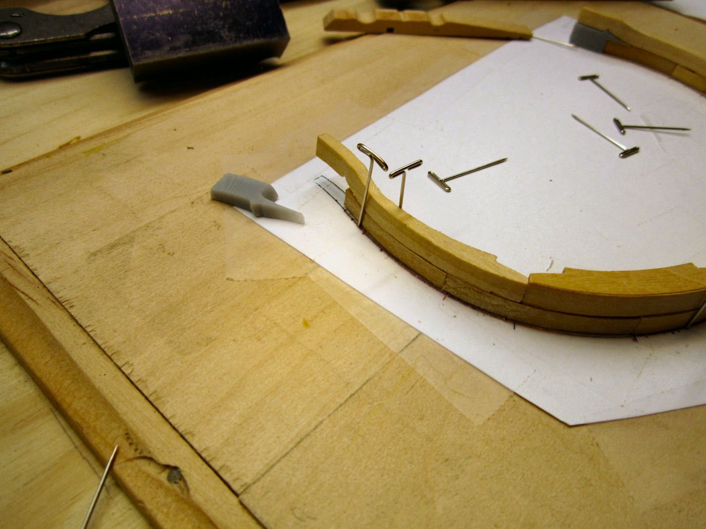
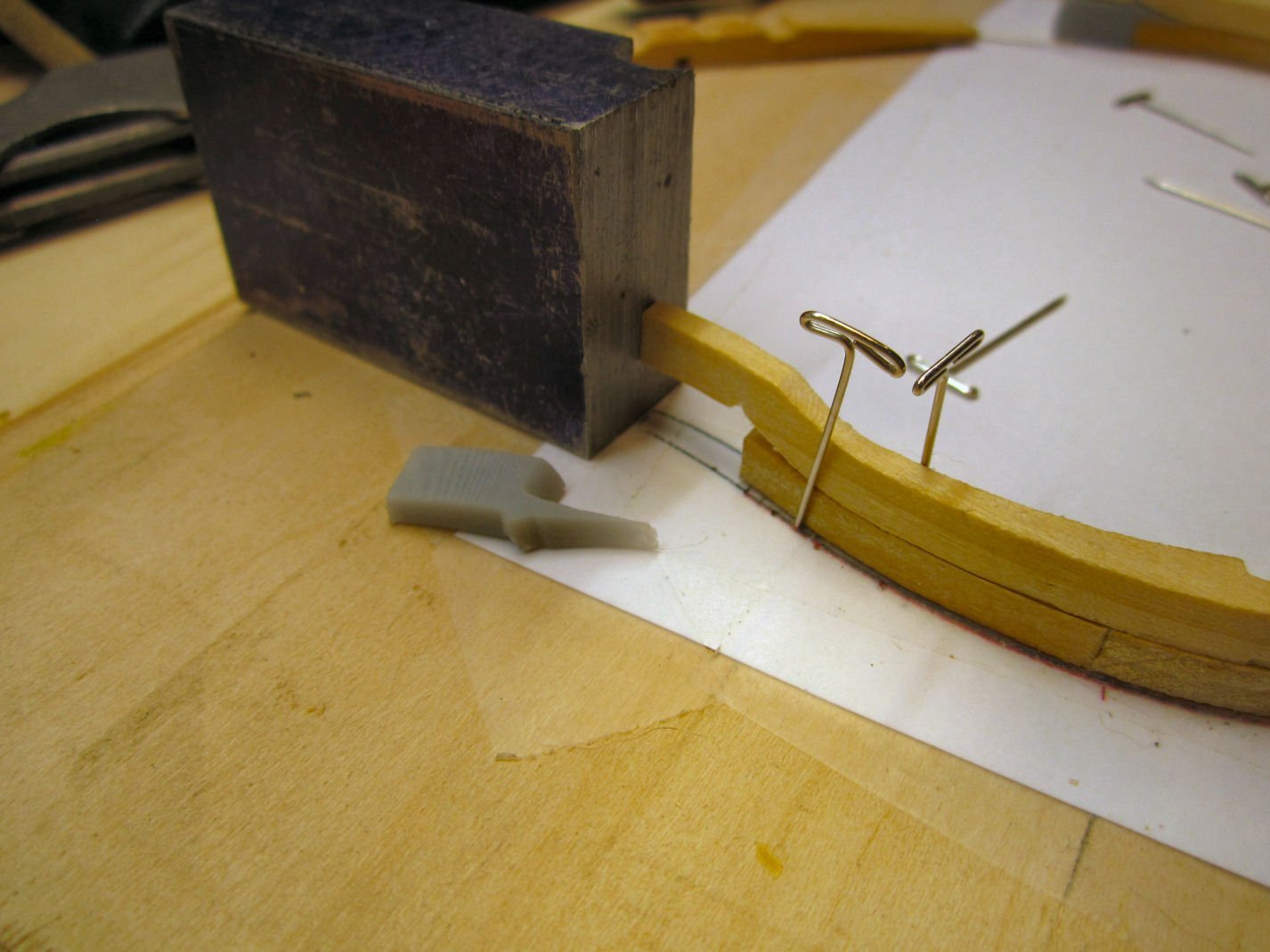
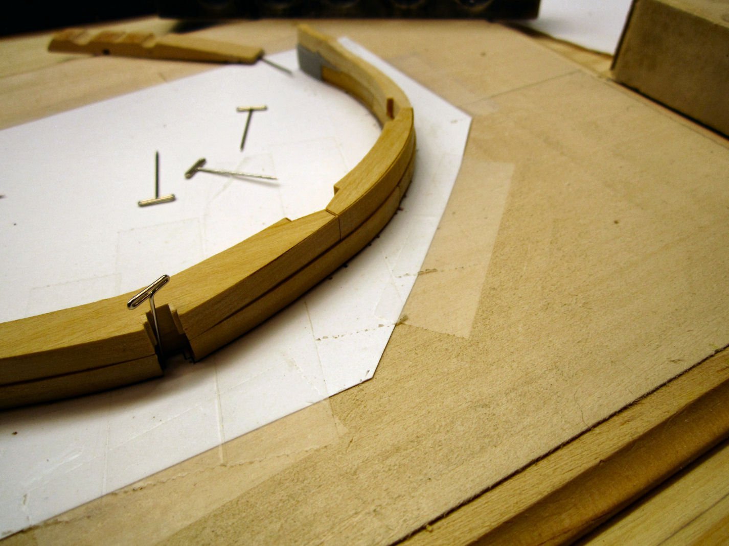
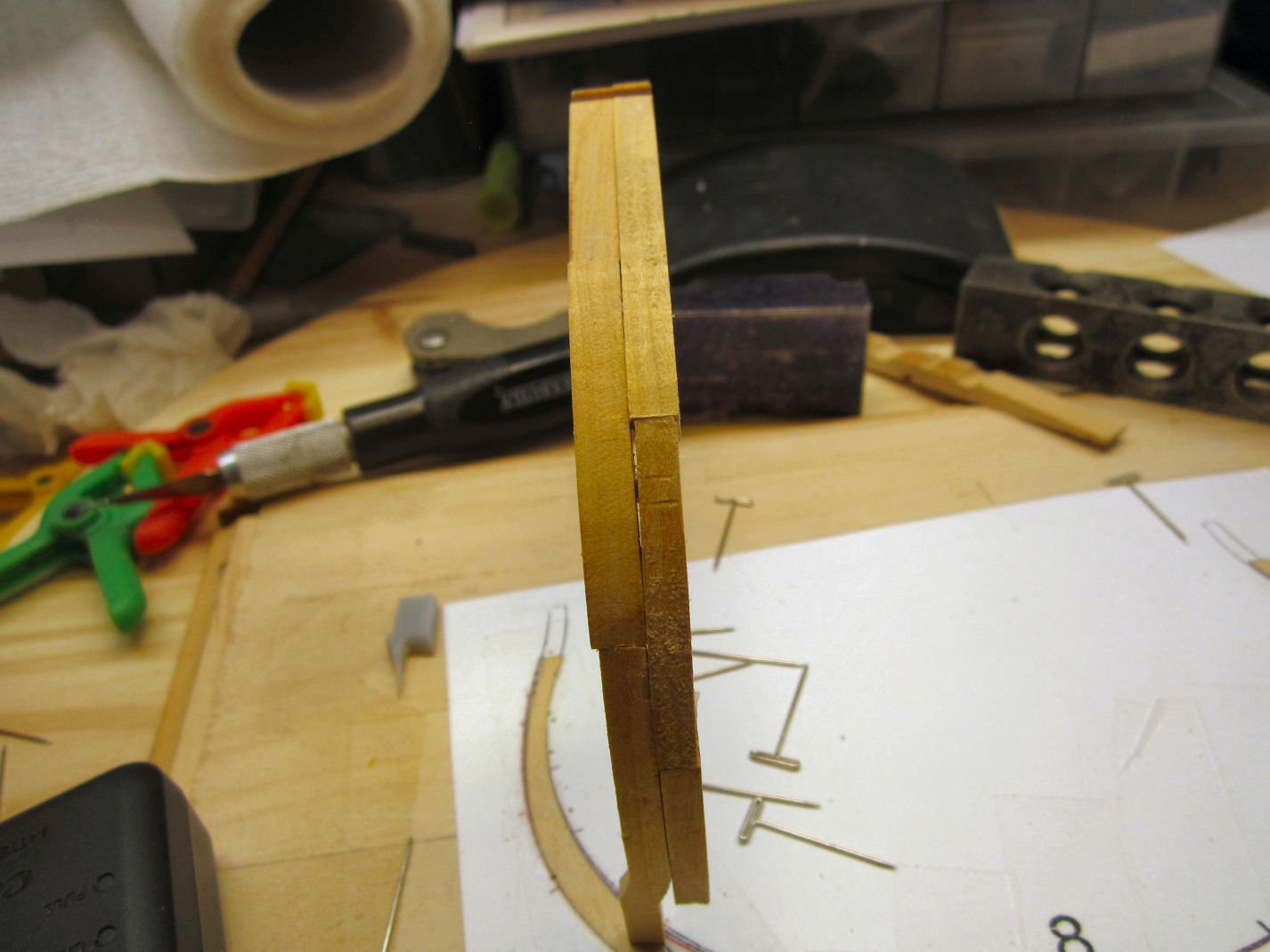
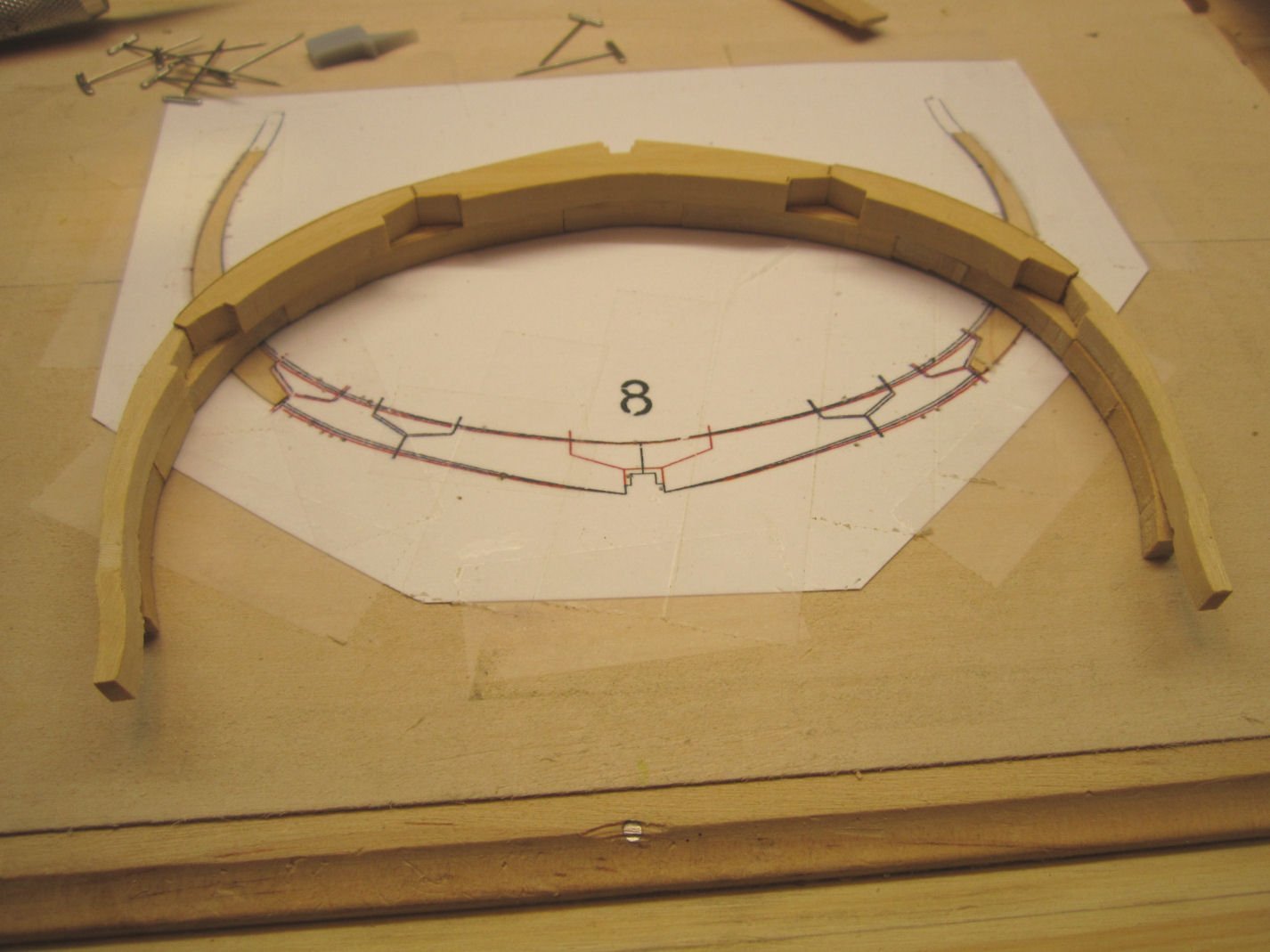
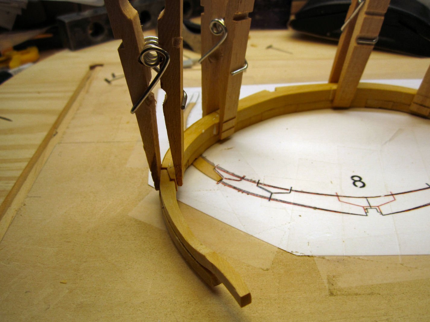
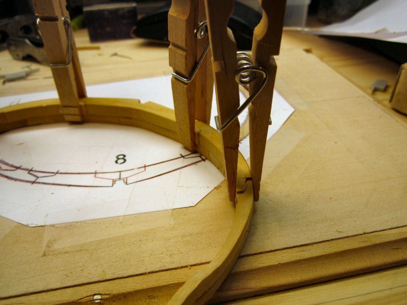
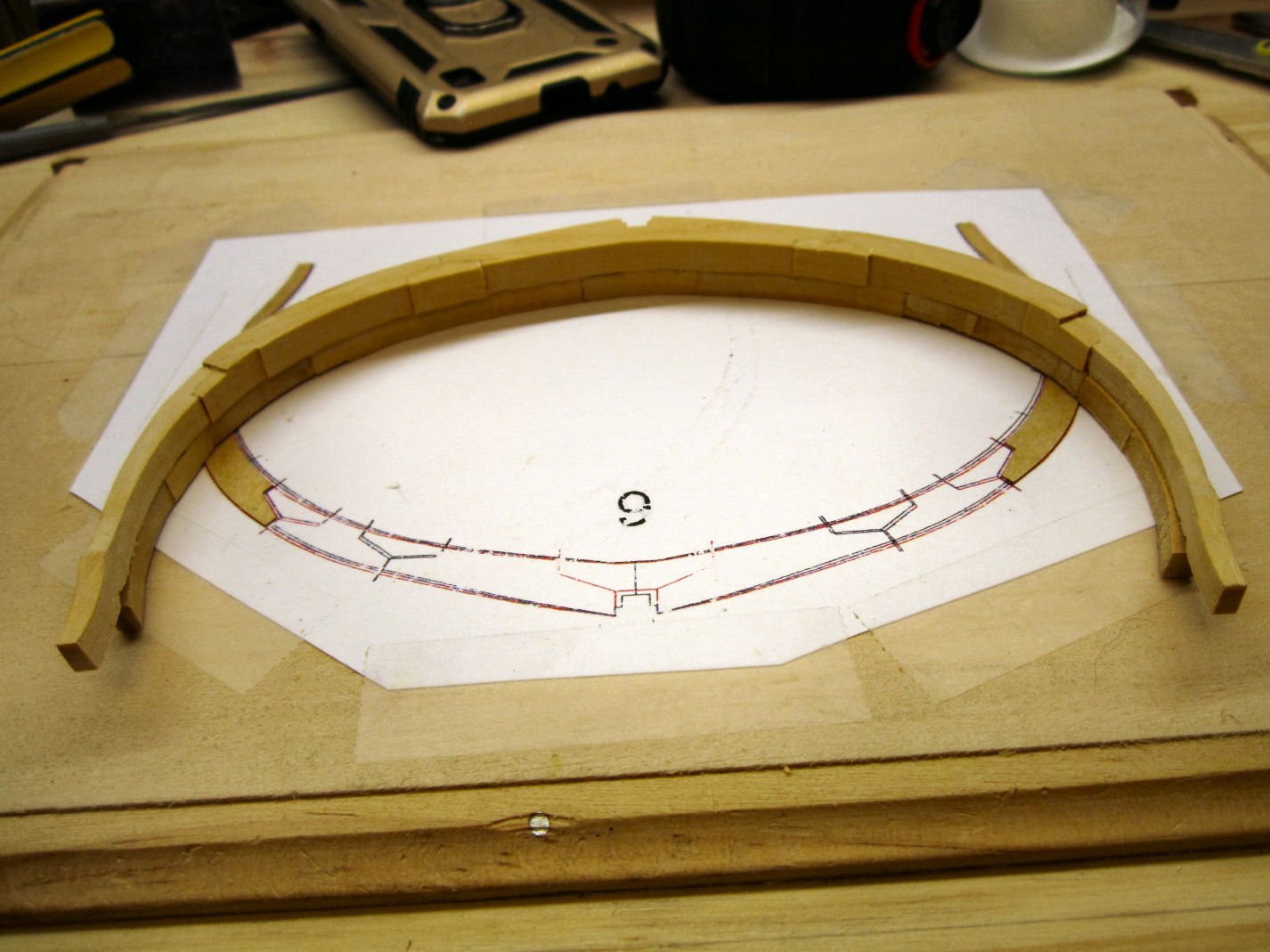
Part 013 There is an error in the instructions for Frame 8. As detailed in the review of this kit by James H. The instructions do not show the part numbers for the shims that need to be attached to the plans before you start to assemble the frame over it. The picture below shows the part numbers. After mounting the scan of the frame drawing, on the build board, I enlarged the slots in the upper frame piece to mate with the resin spacers inserts, that will used later. Frame 8 is where the upper and lower frame halves start to have a significant offset, vertically, from one another along the bottom edge of the frames. They still match at the false keel notch. If you look at the false keel, you will see it is also getting taller as we progress further. I progressed as in the previous frame by gluing the lower frame pieces together at the mating edges, and installing the chocks later. Using another copy of the frame for reference, I glued the bottom section of the upper frame to the lower frame half, orienting the tips so that they were equally space “Up’ from the lower edge of the bottom of the lower half. After this had set, I placed the rest of the frame pieces in place, along with the resin inserts, so that I could get a feel for how they would fit in place. This is where I ran into a problem. The resin insert on the left hand side, was a little too large! It was too long and I could not get the upper top frame to mate with the neighboring piece, without bringing the outside edges much further in, from the outside edge of the lower half, than those on the right hand side! It also seemed too thick and caused the tip to not mate with the lower frame, at the top (the bottom too, but more on that problem later). I tried sanding it, but finally gave up, and used a square block held against the lines on the drawing to position it. Once satisfied, I glued the other pieces in place. Here I found a mistake I had made. When assembling the lower half of the frame I somehow got the vertical spacing between the shim area and the unshimed sections wrong. And there was a gap between the upper and lower frame halves, where the drawing showed them touching. I once again used Isopropyl Alcohol to soften the glue joints in this area, and took them apart. In the end I had to use an additional cardstock shim, on top of the supplied shim to get the correct spacing. The lower frame top piece may have been cut a little thinner, causing the gap. I didn’t go back and compare it to the opposite piece to be sure, I was satisfied that they now mated correctly. The above picture seems to show the top pieces out of alignment on the right side, but this just an illusion due to the camera angle. With that fixed I moved on to installing the upper half chocks. After these dried, I went back and cut the chocks to match the varying surface levels, as detailed in the previous posts. Yes, the frame drawing has mysteriously suddenly morphed into the one for Frame 9! I changed to the next frame before I took this picture. The camera was in the house, when I was cutting the chocks.

-
Also note which country your ship/boat comes from. Europen sails were generally a yellower shade than US sails, during the transition to modern canvas sailcloth (witch the US changed to sooner), and some countries had red sails, at least on smaller craft. The sails on the small French fishing boats, like the Sinagot I'm modeling were red, and even today the existing Sinagots, may have either red or white sails, sometimes both, with the red sails having patches of modern white Dacron cloth
-
Firing a replica 18th century naval cannon - damage
thibaultron replied to Louie da fly's topic in Nautical/Naval History
As an interesting, historical, note. During the battle between the USS Kearsarge and the CSS Alabama, off the French coast, one of the Alabama's explosive shells lodged in the Kearsarge's sternpost next to the rudder, but failed to explode. Had it done so the battle would have ended differently. -
Firing a replica 18th century naval cannon - damage
thibaultron replied to Louie da fly's topic in Nautical/Naval History
The Wasa museum test fired a replica of one of her cannons, against a replica section of her hull. Basiclly a 25 pound cannon ball would go through Both sides of a ship. The only difference between the ball hitjng between frames or at a frame, was hitting a frame created vastly more splinters. Splinters kill and wounded more crew than the actual cannon ball. -
No, he built his from scratch, not a kit, but that one is a beautiful model!
-
Laser Engraving/Cutting - Where To Start?
thibaultron replied to Kevin-the-lubber's topic in 3D-Printing and Laser-Cutting.
Engraving, yes. Cutting would probably require a much more powerful laser, for anything but the thinnest materials, like paper. Also you will need some sort of protective sheet on your printing table, so as not to mark it. -
"Royal Navy Warship" discovered near Riga in Latvia
thibaultron replied to Beef Wellington's topic in Nautical/Naval History
It looks like the bow was salvaged after the wreck, all those bow planks ending at the same non-frame area. May have been removed at the same time as the copper plates. -
An interesting note on the Corliss type engines, is that the valves were partially controlled by vacuum dashpots, like were used on some cars. Most models of them get around this, somehow. Several years ago, there was an article in a machining/steam model magazine, about a modeler that actually build a 1/32 scale one with working dashpots! He also used completely scale nuts and bolts, for which he made his own taps and dies! Some of the bolts had to be viewed through extreme magnification to even see. He also made a complete scale set of tools capable of installing all the fasteners!
-
HO trains and layouts by popeye the sailor
thibaultron replied to popeye the sailor's topic in Non-ship/categorised builds
The boiler hose probably did not have a second floor "Floor". Likely the boiler was two stories high with walkways at the second floor level. Nice build so far! -
Yes, SIG still makes silkspan. The getting it to the UK, though I don't know about.
-
Which CNC Machine to get?
thibaultron replied to KrisWood's topic in Modeling tools and Workshop Equipment
Well I just rechecked the specs, it does come with the z-axis probe. -
Which CNC Machine to get?
thibaultron replied to KrisWood's topic in Modeling tools and Workshop Equipment
Today, "I pulled the trigger" on the new SainSmart 3020 CNC machine. It is a pre-order item, so I'll likely get it next month. I'll post a review when it arrives. Still need to get more bits, and a z-axis probe. I figured that this was about the same price as a 3018 prover with the aluminum motor z-axis conversion. This is setup with a sturdier frame, though I don't know if they will offer an extension kit in the future. I bought it now to take advantage of the free one year software subscription. I'll try that software out, but look for a non-subscrption software when that runs out.
-
The museum may have used wood, to prevent them from having to disassemble the engine in the future to replace deteriorating leather. If, they ever have to move the display, the leather that still looked good may fall apart. I visited the Aberdene Proving Grounds Museum in Maryland many years ago., and they had dragged most of the outdoor equipment around. All the equipment that had any rubber tires pneumatic, or solid (generally WWI had solid), had the old rubber ripped off or almost completely destroyed. It was quite upsetting to me to see the displays thus damaged. Later they placed them on cement pads with axle supports holding the tires off the ground, but the damage was done.
-
I would suggest drilling the threads out of the nuts, so that they slip on and off the cast threads, then a touch of glue when final assembly takes place. The glue will fill the thread area, and a touch of paint will hide the glue. No one will know that the threads are not there.
-
The CNC router I'm looking at takes up about 18" X 12" workbench area, with about a 6" X 10" cutting capacity. I'm going to put it on a shelf above my workbench. Obviously not for large parts, but I will be able to cut most of any bulkheads and small details on it, in the scales I would use. It should also cut things like nameplates, Chesapeake Bay type trailboard carvings, etc. It is even rated for small aluminum carvings. I'll also use it to create replacement keel and false keel pieces for the defective ones in my HMS Granado Crosection kit. I CADed plans for a Maryland Terrapin Smack that it can cut the bulkheads, and deck furniture for on it, as well as the keel and subdeck (in sub sections). I'm also CADing plans for a Santa Fe passenger car, that I may be able to use this to mill the truck frames for. Maybe I'm spending money on it, that doesn't competely justify, but I think I'll get my moneys worth out of it.
-
I don't have a printer yet. It is on the list for next month, after I order a CNC router this week.
-
The Pilgram - Tall Ship - sinks at its berth!
thibaultron replied to thibaultron's topic in Nautical/Naval History
https://www.danapointtimes.com/pilgrim-demolished-no-determination-cause-sinking/ So Sad! -
https://www.soundingsonline.com/news/a-beloved-tall-ship-sinks-in-its-berth