


Mark P
-
Posts
1,774 -
Joined
-
Last visited
Content Type
Profiles
Forums
Gallery
Events
Everything posted by Mark P
-
 Sorry Allan; but I must disagree (I believe!) I am sure that there were some important changes to rigging in the 1770s; will have to check, though. All the best, Mark
 -
Good Evening Chuck; A very impressively executed model. The sweep of the timbers inside the hull when the top template was removed is so smooth and regular that I can't believe it will need much sanding. I can see that you are a very creative and inventive thinker, devising workable and effective aids to assist each step of the construction; and I congratulate you on another very effective and realistic model to add to your already impressive repertoire. I look forward to seeing her completed, and wish you the success you so rightly deserve. All the best, Mark P
-
Good Evening Bill; I have some contemporary records listing dimensions for masts, yards and rigging of English warships going back as far as 1600, if this is what you need. If you can be more specific about what is your particular interest, I can PM you some details. There are surveys going back to Armada times, but unfortunately they only list the condition of the items, and don't give any sizes. All the best, Mark P
-
What are ground toes?
Mark P replied to allanyed's topic in Building, Framing, Planking and plating a ships hull and deck
Good Evening all; Further to Bob's informative reply above, I have just noticed an item in the Navy Treasurer's accounts for the year 1626 as follows: Dressing 49 hundredweight, one quarter & 19lb of ground towes into fine Okam at 12s the hundredweight £29 10s 1d ha'penny. Also Converting of 8 thousand 4 hundred 2 quarters & 1lb of ground Towes into sounding lines, Deep sea lines, white lines, marline, and sail lines at 30s the hundredweight £126 15s 3d It helps greatly that I understood what tow is before I read this. Thanks Bob! All the best, Mark P -
Good Morning Tomek; Congratulations on a lovely model; one that will be a joy to look at for many years. All the best, Mark P
- 26 replies
-
- 1
-

-
- Seahorse
- De Zeven Provincien
- (and 2 more)
-
Did the Royal Navy ever build wooden warships in Irish yards?
Mark P replied to uss frolick's topic in Nautical/Naval History
Good Afternoon Frolick; Bruce is indeed correct; there were several attempts to set up a dockyard at Kinsale, but they always failed due to lack of support and funds, despite much pleading from various interested parties. It is also possible that English shipwrights worried about losing lucrative work to Irish yards, and used any influence they had to stop such developments. In 1672 a contract was signed between Sir Nicholas Armorer and Sir Edward Spragge, and the Navy Board, to construct four 50 gun ships at Waterford in Ireland. However, the contract was cancelled and no work carried out, when Spragge was killed at the Battle of the Texel some months later. All the best, Mark P -
No boats at the jetty? Or are they all filled up with the other 15 and sailed away to give you a bit of peace? Looks like a nice place for a bit of sailing. Interestingly, the sea is exactly the same colour as that which I was looking at here in England off our East coast at the weekend. Have a good break! Mark P
-
Good Morning Gentlemen; I can add some facts to this debate: in the early 17th century, the limber holes were cut in the bottom of the floor timbers, adjacent to the keel. To prevent fouling of these holes, and the spaces between them, a rope was placed through them, known as the 'limber rope', or 'keel rope'. The holes were 3-4 inches square. This is explained in Sir Henry Mainwayring's 'Nautical Dictionary', written by an experienced mariner for the education of gentleman officers who knew nothing of the sea, and of which he produced quite a few handwritten copies around 1630; so this can be taken as a definite feature of ships of the time. How long it continued I cannot say with any certainty; nor exactly when it might have started. However, as Bob says above, the cost of chain, certainly in the earlier periods of sail, would have made its use very unlikely, and I have seen no mention of such in this context. All the best, Mark P
-
Masthead shape on early 17th century ships
Mark P replied to rcweir's topic in Masting, rigging and sails
Hi Bob; Contemporary evidence for masthead details are pretty much non-existent, and most people will probably rely upon extapolating back from the last known true details from later in the century. Cornelisz Vroom painted English ships arriving at Flushing in the early 17th century, and some masthead details can be seen in this; I include a small excerpt below. However, although he supposedly depicts English vessels, he probably shows contemporary Dutch practice. The main point to note, though, is that the mast head is shown round. Whilst this is not definitive proof of English practice, it does seem logical that ships whose mast was made of a single tree would not have a square mast-head. Since at lease Elizabethan times trees for masts had been imported into England from Eastern Europe, so there was no problem finding large enough trees. All the best, Mark P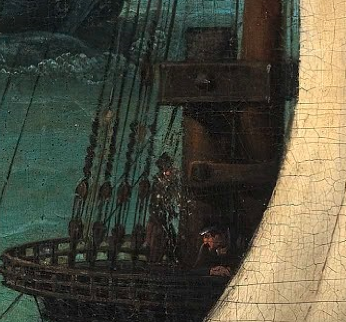
-
HMS SUSSEX by KarenM - FINISHED - 1:48
Mark P replied to KarenM's topic in - Build logs for subjects built 1501 - 1750
That is a beautiful and painstaking model; I congratulate you on the successful completion of it. Well done indeed! All the best, Mark P -
Technical drawings & Dutch shell first
Mark P replied to Jules van Beek's topic in Nautical/Naval History
Good Afternoon Amateur; Jules has included significant extracts from the museum report at the beginning of this post, and they are well worth a read. Whilst I cannot give any opinion on Dutch draughts of the 17th century, I can inform you that English draughts of the period consisted largely of the midship section and a series of curves shown in sheer or plan, called the rising and narrowing lines. These delineated the points on each station at which the curves used for the midship frame were shortened/lengthened and re-combined, in a process known as hauling up or down. The curve radii used remained constant, and for this reason there was no cause to draught anything beyond the rising and narrowing lines. This system appears to have been developed by Mathew Baker in the 1580s, and remained the basis of draughting until at least the reign of Charles II. The relevant points to use on each station could be calculated mathematically with great accuracy, so there was no need to rely upon scaling up or down from a smaller draught, provided that the shipwright possessed the relevant knowledge of mathematics. There is therefore no expectation, amongst anyone with knowledge of this period, of the existence of anything beyond a comparatively simple draught, which would be the technical equivalent of the much later and more complicated draughts which survive in far greater numbers. Early 17th century draughts are few in number, regrettably, although contemporary writings make it clear that they were a routine part of the design and building process, and must once have existed in quantity. All the best, Mark P -
Technical drawings & Dutch shell first
Mark P replied to Jules van Beek's topic in Nautical/Naval History
Good Evening Gentlemen; Discussion of the merits of a stated position is to be expected, and provided that it is done without open rudeness, is all part of the process of justifying one's argument. If an author were to hypothesise that 'It is probable that 17th century Dutch shipwrights did not use draughts', and then for the resulting discussion to demonstrate that they did, the author's credibility, whilst somewhat lessened, is not undermined or damaged beyond repair. However, if an author, accepted as being an authority in his subject, makes a definitive series of statements that "17th century Dutch shipwrights did not use draughts"; and that "17th century Dutch draughts do not exist", and then publicly denounces a collection of 17th century Dutch draughts in a national museum as forgeries, then I would say that that author's credibility, on that subject at least, is effectively destroyed when the museum in question undertakes a series of careful (and presumbly expensive) tests and establishes beyond doubt that the draughts are genuine. The lesson to be drawn here is that one should not make categorical statements unless one is either absolutely certain of their correctness, or unless the writer/speaker is prepared to see their credibility damaged when such statements are reliably exposed as false. If a person is viewed as an expert in their field this carries the privilege that their opinions are listened to and generally regarded as correct. The follow-on from this is that the expert has a responsibility to his/her listeners to exercise great care and ensure that any statements made are well-founded and carefully considered, or qualified. Regrettably it would seem that this is not always the case. All the best, Mark P -
Technical drawings & Dutch shell first
Mark P replied to Jules van Beek's topic in Nautical/Naval History
Good Morning Jules; Thank you for the post no. 53. Some very clear points are made here, ones to keep in mind when Dutch shipbuilding methods are being discussed. It would seem to be rather a shame (to say the least) that available 17th century sources have been, and will presumably continue to be, misinterpreted through what seems to be a combination of both wilful and negligent misinterpretation. English records have also been considerably reduced by fires: at least two at the Navy Office, and the disastrous fire at the Cotton Library, where many Medieval, Tudor and early Stuart documents had been collected. Keep up the good work! All the best, Mark P -
Good Evening Siggi; In addition to the tackle shown in Druxey's post no. 983 above, the fish davit would probably have been moved around using the fore burton tackles and/or the yard-arm tackles. The burton tackles were suspended from the mast below the lower mast cross-trees; and the yard-arm tackles were hung from the end of the yards, and could be pulled inwards by means of the tricing line. Rotating the yard using the braces would have moved any object suspended from the yard-arm tackles. Burton tackles are not often shown rigged on models, and yard-arm tackles, if shown, are normally triced up tight to the underside of the yard. All the best, Mark
-
Technical drawings & Dutch shell first
Mark P replied to Jules van Beek's topic in Nautical/Naval History
Good Evening to all; Many thanks to Jules for continuing with this interesting thread. I would like to add a few thoughts to the comments on the differences/similarities between English and Dutch shipwrights' use of draughts. Firstly, the use of draughts for the design of ships in England can be traced back as far as Mathew Baker, whose beautifully illustrated notebook contains various examples of theoretical drawings, dating from the 1580s onwards. Although these might seem very sparse compared to later draughts, it must be remembered that the method used then was dependent upon the construction of a midship section, and of the various rising and narrowing lines, drawn as curves on plan and sheer. Armed with this information, a shipwright could either set out manually (to scale or full-size) or calculate mathematically, the shape of the hull at all stations fore and aft of the midship frame. There is a very good explanation of this method, well illustrated, in a thesis by Taras Pevny, titled 'Capturing the Curve'; which can be downloaded from the internet. Secondly, one of the illustrations in Baker's work shows a master shipwright at work, drawing a detailed ship's draught using a pair of compasses. Thirdly, the Scott MS, a detailed treatise on the construction of all the curves to be used in the setting out of a ship's draught, along with various rules governing proportions, and which mentions the use of a bow to draw curves, was written by George Waymouth, who died circa 1612. The foregoing make it very difficult not to believe that ship design, in England at least, was based on the construction of a draught made prior to building, and that the proportions of the ship were decided beforehand, based on well-practiced rules governing the relationship of length, breadth and depth, as well as the radii of various curves, well before the end of the 16th century. The Scott MS was originally accompanied by a number of draughts of different types of vessel, both ships & galleys, which, even if they still survive, are in a location which is not recorded anywhere that I have found. There are also methods given to calculate the area within a frame, which is presumably linked to displacement calculations, and understanding the level of the waterline. All the best, Mark P -
Technical drawings & Dutch shell first
Mark P replied to Jules van Beek's topic in Nautical/Naval History
Good Evening All; A big thank you to Jules for posting this, and especially for the news of the tests that were carried out on the draughts. I never really believed that they were fakes, as claimed by a well-known author some years back in an article in the Nautical Research Journal. This was done, I believe, solely to avoid said author's claim that 17th century Dutch shipbuilders did not use draughts until the very end of the century being discredited by the existence of such draughts. I also came across Jules' rebuttal of the fakery arguments very soon afterwards, and I know that another expert in this field was also highly sceptical of the claims of fakery. Regarding the rowing layout above, an interesting layout of the rowers is shown in a contemporary model in the NMM at Greenwich. See below. I am not suggesting that this is what was done here, as the thole pin layout is symmetrical, but it does offer the possibility of a wider choice in the rowers' positions. All the best, Mark P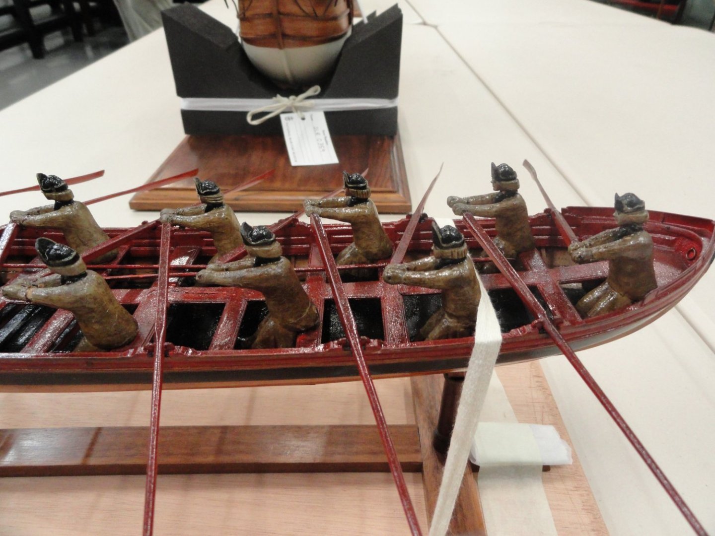
-
Gun Port Hatches
Mark P replied to acaron41120's topic in Building, Framing, Planking and plating a ships hull and deck
Good Evening Gentlemen; I am going to put a cat among the pigeons here, as I do not believe for one moment that the ports were separately lined with timber to form a rebate. For modelling purposes, this may be the easiest method to construct such a rebate, but in full-size practice this would entail a great deal of work, for no practical return. It is much easier simply to stop the outer planking short of the gunport, with the resulting exposed part of the main timbers of the hull frame, and of the inserted cills at the bottom of the port, forming the surface against which the closed port-lid would rest. (Allan, thank you for your pictures above; but they only show that a rebate was present, and do not in any way provide an illustration of how it was actually formed physically in the ship) The framing plan of Vengeance, a 74 of 1774 (available on Wikimedia Commons at high resolution) shows the timbers forming the gunports quite clearly, and on the lower deck the gun-port opening between the timbers scales at 3'4"; and for the upper deck ports it is 2'10". Furthermore, in places the timbers forming the side of the port are shown actually reduced slightly in width, as compared to the width of the same timber below the port cill, in order to increase the width of the port to the desired size. It is, in my opinion, very unlikely that the timber would be trimmed back, only to be later replaced with a separate piece of plank nailed to the side of it in order to replace that which had already been taken away. Just about every contract ever written at this period specifies a minimum for how much timber is to be left to the sides of the ports when the timbers are cut back to obtain the desired width of opening; so obviously trimming back the main timbers to give a desired opening width was common practice. The 1745 establishment gives the gun deck ports of 70 & 80 gun ships a width of 3'5" & those of the upper deck either 2'9"or 2'10". At a later date, for a 74 gun ship, Steel gives a width of 3'5" and the shipbuilder's repository 3'6". For the upper deck they give widths of 2'11" & 2'10" respectively. In other words, the distance shown between the timbers on the framing plan of the Vengeance matches the given dimensions for the width of the gunports. So there is no room for any additional planking to be fitted to the side of the gunport openings. The Shipbuilder's Repository also gives a dimension for the port stops of 3 1/2" for the gun deck ports of a 74. This is the distance by which the outer planking stops short of the side of the timber forming the side of the port opening. The author also gives a size for a 'lining' of 1 1/4"; this is given under the heading of 'Port Lids', NOT gunports, and refers to the thickness of the vertical planks which were fitted to the inside face of the horizontal outer planking of the gunport lids, this inner lining being sized to fit between the timbers at the sides of the ports. The cover illustration by Ross Watton, for Peter Goodwin's book, 'Sailing Man of War', which is based on a model of Bellona in frame, shows this concept very well. Below is a sketch I made some time ago to illustrate the point made above. Gun port details001.pdf All the best, Mark P- 12 replies
-
- 11
-
-

-
Good Afternoon Grandpa Phil; As a further reason to have faith in Mathew Baker's picture, I can add that during my researches into ships of late Elizabethan and early Stuart period, I have come across frequent references to the sides of the ship being 'layed' [painted] 'into colours', that is, plural; more than one colour. A popular colour for the rails (which ones is never specified) seems to have been brown. All the best, Mark
-
Good Evening All; Re the cow hooves on the shoes to disguise shoe-prints, Sir Arthur Conan Doyle wrote on of his Sherlock Holmes stories based on a murder which was carried out by men wearing the same sort of thing, to leave cow-prints in the ground. All the best, Mark P
-
Good Evening gentlemen; Further to Bob's quite correct comment above, I seem to recall that an additional clue to the ship's shape was either the survival of the rivets (very rusted) holding the clinker planks together, or a patch of rust-coloured sand where the rivets had been. All the best, Mark P
-
Thanks Dave; That is a really useful post; the videos are straightforward, clear, and inspiring; and the technique is made very clear, and is so simple throughout. All the best, Mark P
-
Good Evening All; The NRG has two spiral bound books of 'Ship Modeler's Shop Notes', which can be purchased. Vol II contains, on page 50, a section describing how to make one's own miniature carving chisels. I have done this, and not only is the process a fascinating learning curve, well worth it just for the understanding of basic blacksmithing which ensues; the results are very good also. I have some very sharp chisels in a range of sizes, although I must admit that I have not yet made any gouges, only flat chisels. Gouges will follow though, and their making is also described. All the best, Mark P
-
Good Evening All; I absolutely agree with all the comments above about the quality of Chuck's craftsmanship, and the level of skill required to develop a kit. To add to the debate about the model of the Endymion, which is indeed a very beautiful model, this is the 44 gun ship of 1779. She was photographed in the archive store of the Science Museum, and was formerly on display in the Museum, where the model was correctly labelled as the Endymion. When the Museum display was dismantled, there was some mixing of models, I think, because at the time the photographs were taken, the model was actually catalogued/identified as a 74 gun ship, I believe it was the Ajax. I am not certain of her whereabouts now, as the model of the Ajax was returned to the former Royal palace at Kew, from whence she had apparently originally come; but unfortunately, it appeared that the model of the Endymion had been returned in place of the Ajax. Whether this has been corrected in the intervening years or not, I am not aware. I will have to visit Kew one day and try to see what I can discover there. For those who are interested, the photographs of the model are in the gallery of completed models on this website. All the best, Mark P
-
Good Evening Marvic; I am not an expert in this particular period, but I would say that the illustrations are much later than the early 1300s. The vessel shown on the right has multiple masts, and her superstructures would appear to place her in the mid 1400s at the earliest. The left-hand vessel has two masts. Multiple masts were something which happened over a relatively short period, with the transition from single masted vessels to two or more masts occurring within about 50 years, if my memory serves me at all reliably. If your interest is serious, and it seems to be, I would suggest the following two courses of action: 1: contact another member of this website, Stephen, from Australia, who has a deep knowledge of this period, and posts on here under the name of 'Louie da Fly'. 2: try to obtain a copy of the book 'The Good Ship', by Ian Friel. This covers the development of ships in this period in much detail, with in-depth discussion of the various stages of mast numbers, and fore and after castles. All the best, Mark P
-
Good Evening Steven; An interesting question; I see no problem with accepting that your second picture corroborates the first. Re the loop of rope used to attach to the yardarm, if one accepts that two anchorage points is better than one, because the load on each leg is much reduced if there are two, then one must conisder how this would work as the yard rises, and the angle of the two legs relative to the yard changes. When the yard is fully lowered, the legs will be at their closest point to being equal, although the inboard one will always be shorter. As the yard is raised, the angle of the lift becomes much closer to the horizontal, and the difference between the leg lengths changes significantly. If the main lift block was simply seized to a bight in the rope at the yard-arm, then, as the yard rises, the inner leg would slacken, and all the stress would be on the outer leg only. By allowing the bight of the rope to move through the sheave of the lower end of a sister block, the stress remains equally distributed through both legs, regardless of how much their lengths change relative to each other. All the best, Mark P
