Mark P
-
Posts
1,774 -
Joined
-
Last visited
Content Type
Profiles
Forums
Gallery
Events
Everything posted by Mark P
-

Bow & Stern blocks
Mark P replied to DaveBaxt's topic in Building, Framing, Planking and plating a ships hull and deck
Good Morning Dave; A general tip which applies to wood purchased from DIY stores, builders' merchants & non-specialist timber merchants, is to let it season for as long as possible. Most wood from these sources is recently converted from logs, and has a high moisture content. If you intend to do much in the way of filling blocks, buy the wood now and lay it by, ready to use in the future. This will avoid the risk of shrinkage after you have carefully shaped it and covered it with planking. All the best, Mark P -
Treenail holes
Mark P replied to Don Case's topic in Building, Framing, Planking and plating a ships hull and deck
Good Evening gentlemen; That's a whole load of interesting information there. It would appear that I have misunderstood the method by which treenails were caulked, and that this, in this context, means that the caulking was used as a wedge. With regard to paying the seams, though, whilst the meaning of this is clearly understood in terms of the waterproofing of the seams of the deck planking with hot tar, the verb 'to pay' was also used to describe a different activity. This was the regular treatment of the hull below the waterline with hot tar, or other compounds, brushed on. This was carried out at regular intervals, maximum every three years, normally, often much more frequently than that. The whole of the lower part of the hull was so covered, and this process was called 'paying' the ship's bottom. The ship was first careened. That is forcibly laid over hard, almost onto her beam ends; which was normally done on a hard area of shingle. By this means, one complete side of the hull was made accessible. Its existing coating of tar would then be softened by burning with bundles of dry reed, set alight and held in special metal rods, rather like arquebus rests. The softened tar was then scraped off, and the new coating of fresh tar was applied. Apart from the actual careening, all of these activities were carried out by the caulkers, working, in the Royal dockyards at least, under the direction of the Master Caulker. This coating of tar would have closed off the seams between the planking below the waterline, sealing in the oakum. The tar was then covered with a layer of 'anti-fouling' made of oil, brimstone and rozin. The boundary of the tarred area was the 'black strake', which was normally the first strake above the wale; below this all was tarred. Above the black strake, as has been mentioned in other posts above, the seams in the sides of the ship, after caulking, were stopped. This was normally done with putty, and in the Royal Navy was actually carried out by the painters, as part of their works. All the best, Mark P -
Treenail holes
Mark P replied to Don Case's topic in Building, Framing, Planking and plating a ships hull and deck
Good Evening Gentlemen; I have to agree with Bob, in that it seems counter-intuitive to caulk treenails; and I was surprised when I first came across references to it, for treenails do, as mentioned, swell when wet, ensuring a good grip. Allan's post has provided sufficient contemporary evidence for the practice of caulking the treenails (thanks Allan; saved me from digging them out; and my contracts don't go into the 19th century) Whilst it may have been different in the merchant fleet, this was probably done because warships were not always in commission. If laid up in ordinary, they were moored in the river, and in hot weather the timber would all shrink, planks and treenails both. This was a known problem, and I have seen complaints that the ship's standing officers failed in their task of keeping the ship's sides wet in such weather, allowing seams to open and treenails to become loose (they were also meant to open the hatches and ports to allow the air to circulate to prevent rot, yet they frequently failed in this task as well) The same hot weather would also make any pitch soft, allowing it to move at least somewhat with the wood. Pitch was applied to the seams using a rectangular shaped funnel, with a long narrow slot in the bottom. Using this correctly on side planking must have been somewhat of an art, involving sliding it along the seam slowly, whilst someone else poured the hot pitch in at the right rate. For treenails, though, I have no evidence for how it was done; quite possibly with a brush (dockyard orders for consumables include a huge number of brushes of various types, although most of these were for paying the bottom and sides with white stuff or black stuff, or whatever other finish was needed) Further evidence that this was done, somehow, lies in the origin of the widespread old saw 'there'll be the devil to pay'. This, if I remember correctly, evolved amongst shipwrights; where the 'devil' is the name of the lowermost seam in the ship, of the garboard strake, which must have been awkward to get at. The fuller, older version of the old saying is: 'There'll be the devil to pay and no pitch hot'. All the best, Mark P -
Treenail holes
Mark P replied to Don Case's topic in Building, Framing, Planking and plating a ships hull and deck
Good Evening All; If one wished to be really pedantic about treenailing, it would be necessary to take into account the fact that in various locations where particular strength was required, it was customary to use bolts instead of treenails. This was done, for example, with the binding strakes and spirketting, and with the plank of the bottom from the wales downwards. All butts in these locations had bolts in the timber immediately before the one on which the butt lay. Bolts were not left exposed, though: they were sunk below the surface, and a diamond shaped cover-piece was inset into the plank to hide them. As the grain of this diamond was parallel to the plank, this would be almost invisible, thereby causing noticeable blank spots in the pattern of treenailing. However, the cover piece was caulked and payed, which would have led to it being rather noticeable. Frequently, treenails were also caulked, with caulkers using curved irons to drive the oakum home. This presumably meant that the caulking was also payed in these locations, to prevent the oakum rotting. So again, they would actually have been rather visible, as dark rings, though; rather than wood circles. However, I do tend to agree with Bob Cleek on this matter; very few Georgian era models have treenails in their planking, and I believe that they look much cleaner for it. Thousands of overly-noticeable treenails give the models an appearance of having some kind of disease, and distract from the aesthetically pleasing flow of well-laid planking runs. All the best, Mark P -
Good Afternoon Allan; A good idea; especially as there is a brand new book of their collection out today, or tomorrow. See Seaforth Publishing, I think. All the best, Mark P
-
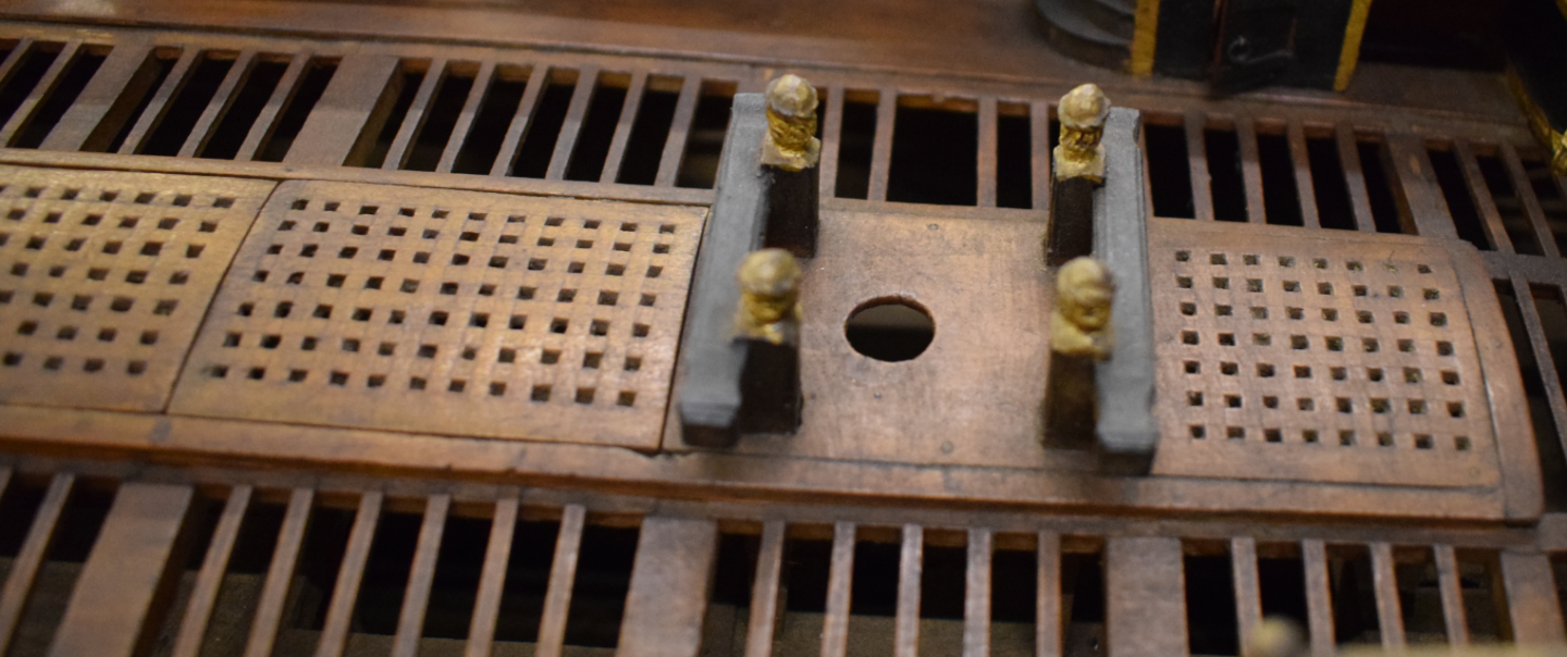
Good Morning Allan; I have looked through my pictures of models from the 17th century, and most of them show what can only be interpreted as half-lap joints. One has mitred corners. Most hatches and coamings seem to be simplified, made in the most convenient way for the modeller. Below is a clipping from the NMM's model called the 'Bonaventure', although this ID is not considered reliable. 1680s. Have you checked through any of the Kriegsteins' books on their collection? Might be a useful illustration in there. All the best, Mark P
-
Good Morning Bill; I would be very dubious about placing too much reliance on any of the pictures you show being a true picture of the Marie Celeste, except the first one in this post, which is presumably known to be her. TV production companies, or video editors, are likely to take considerable liberties with the truth; and the last picture is obviously a generic image of a much larger ship, with three masts. The Smithsonian may have taken some trouble to give a good resemblance to her for their video, but one cannot be sure without checking. I only mention these thoughts so that you do not feel too cut up about not matching your model's appearance with any of the more dubious images posted. All the best, Mark P
-
Definitions
Mark P replied to Don Case's topic in Building, Framing, Planking and plating a ships hull and deck
Good Evening Gentlemen; The word 'Harris' in this context is a not uncommon misnomer. The word is actually 'Arris', which is a common term in stone masonry and carpentry, and is in regular usage amongst craftsmen. I believe that it actually is derived from either French, or Norman-French. It means a sharp edge or any corner formed by planes meeting at up to 90 degrees or so. However, many architects, or clients, on the mistaken assumption that the craftsman they overhear talking of the 'arris' is actually dropping the letter 'H' from 'Harris', which is a widespread habit amongst many English speakers, then refer to the 'Harris' in a misplaced desire to speak 'properly'. This is the derivation of the 'Harris' as a technical term, but it is totally erroneous. As an example, the horizontal timber used in fencing, which is triangular in section, and against several of which the vertical pales are fixed, is known as an 'arris rail'. So the correct term for which Don is seeking a definition is 'arris cut'. All the best, Mark P -
Good Morning Darius; I agree with your comments. Whilst Frank Fox certainly has criticisms of McKay's book on this subject, he did not condemn it in its totality. What he wished to emphasise the most was that although he is cited in the introduction, thereby implying that he had a part in its contents, he did not endorse the book, and does not support much of what is shown; and most especially, his advice was given on some parts, but not adopted. As Darius and others have mentioned, the book is worth having, even if only for the drawings of the decoration. The quality of the draughtsmanship is indeed acknowledged by Frank Fox, as being practically the book's only merit. All the best, Mark P
-
Gun ports in the waist
Mark P replied to allanyed's topic in Building, Framing, Planking and plating a ships hull and deck
Good Morning Allan; I believe that the change occurred in the 1680s at the latest, but I will have to check on this, as I have no copy of a Navy Board order directing this to be done, unless it was part of an order dealing also with other things. The younger Van de Velde's well-known painting of Resolution in a gale shows her without waist lids, see below. All the best, Mark P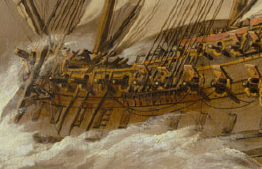
-
For any who might be interested, I posted a review of Richard Endsor's most recent book, 'The Master Shipwright's Secrets', in the books section; and also on Amazon. It is a very well-researched and most informative work, with some wonderful fold-out plates by the author, who is an accomplished artist. All the best, Mark
-
Good Evening Allan; 1715 it was; surprisingly, although saving timber was one reason for adopting this measure, the main consideration seems to have been to prevent decay, which was more prevalent in these areas. Perhaps because a square frame with a large bevel results in a much longer mating surface between the frame and the planking, thereby trapping more moisture than would a canted frame with its shorter mating surface. All the best, Mark
-
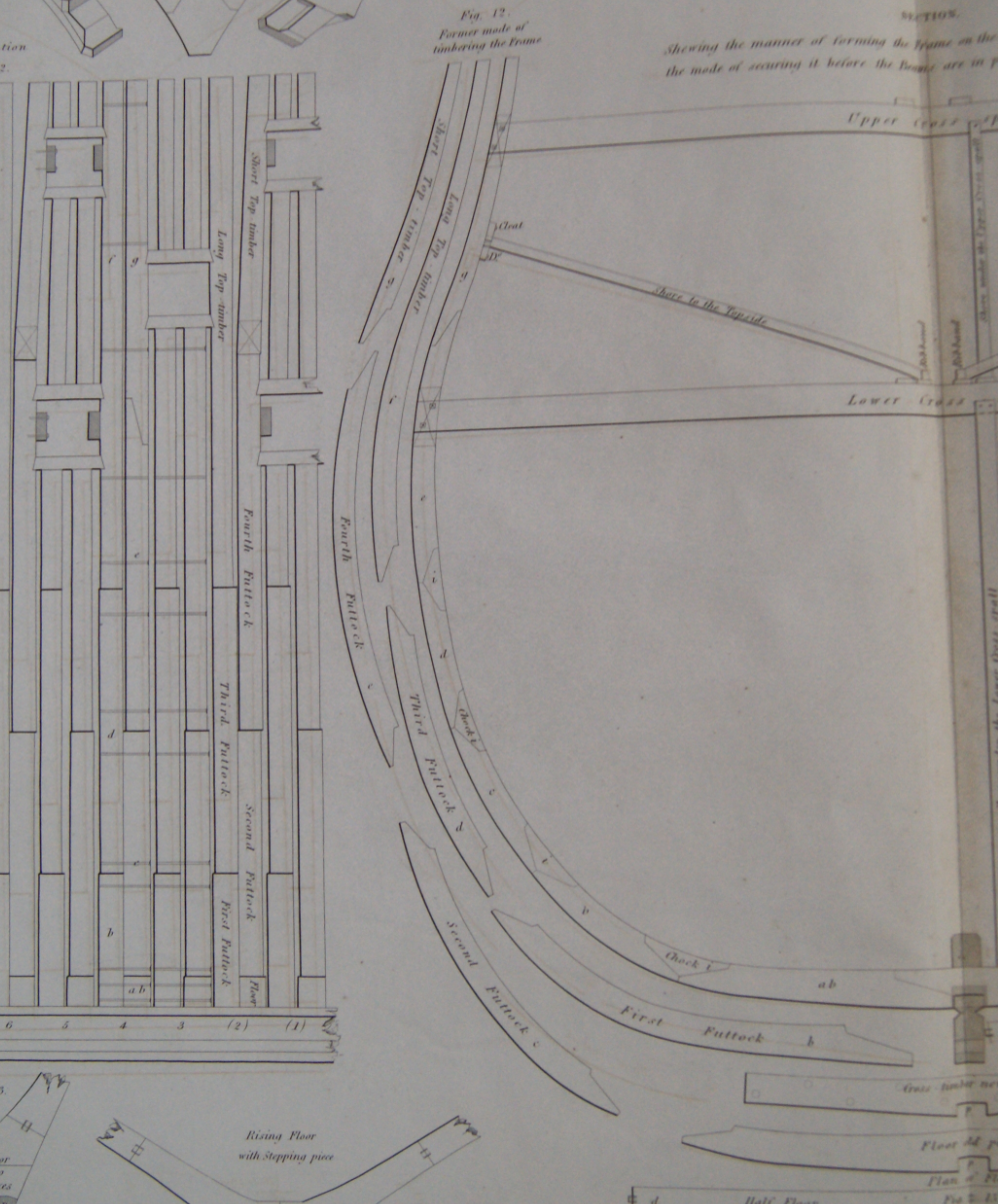
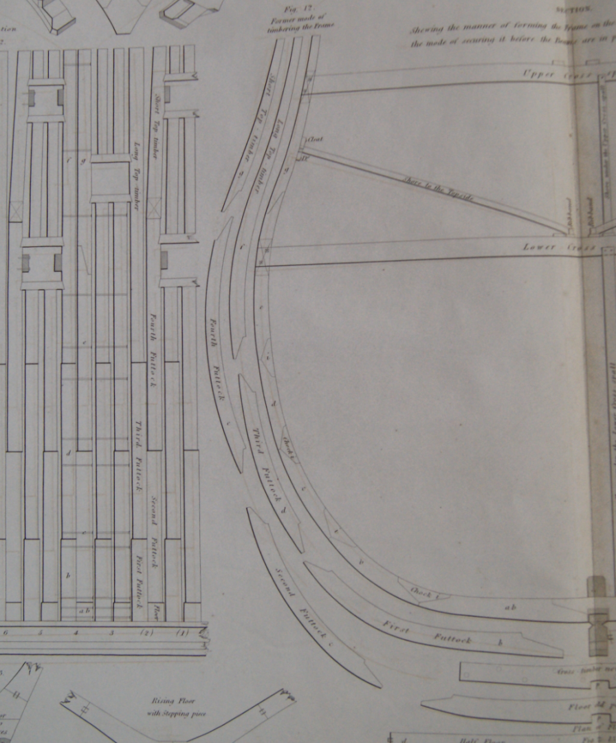
Good Morning Druxey; I don't possess as many disposition of frame drawings as I would wish, most regrettably, mostly dating from the 1780s. On the majority of these, while the joints in the lower futtocks are indicated by a single line, the uppermost joints, to the shorter top-timbers, are indicated by two lines, the correct distance apart for a scarph, with the lower line frequently dashed. This difference in treatment can only indicate a scarph joint as opposed to a chocked joint. The earliest of those which show this is Bombay Castle, dated Navy Office 1779. On only one frame plan are Xs drawn between these two lines, though, which would indicate to me that an X was not always shown. This has also been described in writing, but I cannot recall if this was in a modern or contemporary work. It would certainly be interesting to know how far back this method extended. All the best, Mark P
-
Rigging Confusions - Lifts, Halyards and More, Oh My!
Mark P replied to rraisley's topic in Masting, rigging and sails
Good Evening RR; I think that the best solution to your dilemma is to try and purchase copy of James Lees' book 'The Masting and Rigging of English Ships of War, 1625-1860. This describes the rigging of a variety of ship types through a long period, and goes into all the sort of detail which will answer your questions, and all the others which you haven't yet asked as well! Copies can normally be found on Amazon, or try Bookfinder, which currently has them starting at £35, up to the best part of £200. If you are in the US, they are also available there. All the best, Mark P -
Good Evening Don; To expand upon Allan's quite correct explanation, the dashed line shown in the framing plan in my earlier post is the profile of the station line of the double cant timber, when viewed from a point square to the keel. It does not represent any line shown on the body plan, and is obtained by extrapolating from the cant timber lines as drawn on the half-breadth plan. The dashed lines of the cant stations are never shown on the main draught of the vessel, and only appear on the framing plan. All the best, Mark
-
Good Evening Druxey; You are quite correct about the rationale behind the use of chocks, they do enable the use of shorter or less curved timber. However, by reason of the top-timbers having little curve, and, especially towards the stern, being almost straight, the use of chocks conferred little advantage from the point of saving timber, and actually involved more work, in that cutting chocks and their mating joints involves four angled cuts, whereas a scarph involves cutting only two. John Fincham, who was headmaster of the Naval Academy at Portsmouth, illustrates this very clearly in the plates which accompany one of his books (can't remember which, unfortunately!) His plate shows the practice in the time shortly before Seppings' reforms introduced the dowelling together of futtocks, but is certainly applicable to much earlier decades, for the reasons outlined above. I have also seen earlier illustrations showing the same thing, and have seen it in written descriptions. All the best, Mark P
-
Good Morning Lieste; You are quite right regarding Steel; however, that is a good example of why his authority cannot necessarily be extrapolated backwards in time. The method he uses was introduced in 1794, I believe. Prior to that, the mast length was either based on calculations using the beam, or the keel and beam. In the 17th century, keel, beam and depth were used in the calculations. All the best, Mark P
- 19 replies
-
- 3
-

-
- running rigging
- standing rigging
- (and 1 more)
-
Good Evening Marcus; To follow on from Bob's post above, the United Provinces, as the Netherlands was then known, were probably the worst offenders in the variable foot field. Each of the administrative districts had its own foot. Must have been a bit of a nightmare for journeyman shipwrights. Regarding the rigging, the essential point is that it was done by rule of thumb, and in most countries everything started off with the length of the mainmast, with everything else based on a particular fraction of its length. The divisor applied varied from country to country and from period to period, but knowing the mast length meant that those with the correct knowledge could calculate the diameter of all other ropes. The length of the mast was, in Britain at least, based on calculations using the length of the keel and the ship's beam. On the subject of Cook and Australia, it was indeed known that there was something in the area; I have seen a French map dating from around 1715, which showed a line south of the main East Indies, marked as some kind of unknown land. But Cook was the first to prove its size and survey so much of its coastline. All the best, Mark P
- 19 replies
-
- 3
-
-
- running rigging
- standing rigging
- (and 1 more)
-
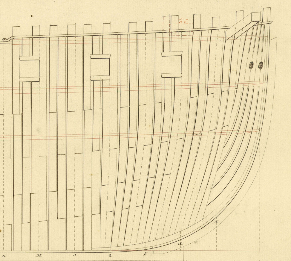
Good Evening Don; In the English Navy, cant timbers continued the pattern of the main frames, in that (for example) two filling frames were followed by a double frame (I hesitate to call a double cant timber a 'bend') The pattern of scarph joints was continued from the square frames, except in the lowest timbers, which no longer had to straddle the keel, so the lowest scarphs were no longer needed. The uppermost joint was normally a plain scarph joint, without a chock, as with the square top-timbers. The longest futtocks of the double cants were called 'half-timbers'. This may also have applied to those of the filling frames, but my memory not powerful enough to recall this for sure (need a few more MB inserting) See below an excerpt from a framing plan which shows the bows of Andromeda of 1784 The dashed line is the station line of the cant, centred on the joining faces of the double frame. Note that the station line location, as drawn at the keel, did NOT give the position of the station line at the keel, but at the height of maximum breadth. For example, in the clip below, the 'S' near the boxing is not below the bottom end of the dashed line, but is vertically below the line of station 'S' at the foremost point, which is the maximum breadth (note that this does not work any longer as the maximum breadth becomes, in theory at least, the flared out part of the top-timbers) All the best, Mark P
-
Good Evening Gentlemen; Not sure if anyone is still looking for this, but there are various copies advertised on the 'Bookfinder' website. The below version is not cheap, but there are others. I picked up a decent copy through that same website a while ago, for much less. The shipbuilding manuscript is also for sale on the same site. All the best, Mark P

-
Good Morning Gentlemen; an interesting topic; I have checked my photos of ship models, and all the 74s, which are Ajax, Egmont, & Warrior, have backstay deadeyes on both fore and main masts, either as a narrower extension on the aft end of the channels, or as a separate stool; but no stool or deadeyes on the mizen channels. I also have pictures of the Thunderer/Hercules (which I strongly believe is actually Hero) which does have mizen backstays on a stool, but this was rigged in the NMM in the later 20th century, and these just might have been added then. Although looking at the as-built draughts, which again all show backstays for the fore and main masts, Ramillies, 1785; and Warrior do show a separate backstay stool for the mizen. Yet the draughts for Alfred and Cumberland do not show a mizen backstay stool. It is perhaps possible that the mizen backstays in some ships were set up with a lanyard to an eye-bolt in the topsides outboard. However, it is interesting that the model of Warrior shows her without backstay deadeyes, yet the as-built draught does show them. Draw your own conclusions! All the best, Mark P
-
Good Evening Allan/Roger; I can confirm that none of the contracts held at either the NA or at the NMM have been digitised. The NMM ones are available as copies, but the last I heard this was an expensive service. At the NA, search under ref ADM 106/3071. This will bring up what looks like a bunch of contracts dealing with sick and wounded, but is actually largely comprised of ship contracts. Amongst these are several for 10 gun ketches of 1690-94. However, the index entry online is brief, and does not list the documents individually. There are a couple of earlier contracts for ketches from 1664 in the State Papers, but these are not generally available, as they are restricted access documents; obtaining copies of these would perhaps be possible via the NA's copying service. However, they are very brief, and do not give a lot of detail of the structure; unlike the ADM ones, which are several pages long. All the best, Mark P
-
National differences in rigging?
Mark P replied to Smile-n-Nod's topic in Masting, rigging and sails
Good Afternoon Brett; If you really seriously want to know the differences, and your interest lies in the 18th century, I recommend that you obtain a copy of 18th century rigs & rigging, by Karl-Heinz Marquardt. This gives in great detail the rigging of ships of many nations. All the best, Mark P- 1 reply
-
- 3
-
-
17th century English merchant flags
Mark P replied to Louie da fly's topic in Nautical/Naval History
Good Evening Stephen; Druxey is correct, but they flew the St George's cross also. Timothy Wilson's very useful book 'Flags at sea' gives the following for merchant ships, set down by a royal proclamation in 1674: 'The Flag and Jack White, with a Red Cross (commonly called the Saint George's Cross) passing quite through the same [that is, filling the whole flag, not in the canton] And the Ensign Red, with the like Cross in a Canton White, at the upper corner thereof next the staff'. English merchant vessels were banned from using the Union flag as flown on the King's ships from 1606. However, it would appear that many vessels ignored this ban, as it brought exemptions from various duties and requirements in some foreign ports, and helped to prevent having crews pressed; as well as, presumably, helping to discourage pirates from attacking what might be taken as a warship from a distance. That the ban was widely ignored is illustrated by various attempts to stamp out the practice, including by Samuel Pepys; seemingly without much success, as such attempts and various proclamations prohibiting it, continued into the 18th century. Various official trading organisations, such as the East India Company, also flew their own flag. all the best, Mark