robnbill
-
Posts
841 -
Joined
-
Last visited
Content Type
Profiles
Forums
Gallery
Events
Everything posted by robnbill
-
 Thanks Mark. At this point, I think I would pass on them anyway since nothing else has been purchased in near finished form for the ship and I hope not to have too. The cannon were my last big hurdle. I know I can make rope I just need to get a suitable ropewalk. The masts, etc, I made on the Connie so I know I can turn those. Now you do raise a good point though. I know there are home etching solutions. I have never tried one. I will have to look into that. Druxey, thanks for the clarification. I did sort of run two thoughts together. I was researching the trunnions for the long guns and the elevating screw for the carronades. For the Eagle, Crisman showed the Carronades mounted on a central hinge underneath the barrel as you said. That is what I was testing. My question regarding the carronade was if I should use an elevator screw or not. I think I will follow your advice as well on that and not include one.
 -
Thanks for everyone's input and pointers to more information regarding the cannon/carronades and gun locks. It has been greatly appreciated. I will have to investigate the practice around the time on where the trunnions were located. I believe the TFFM also recommends below centerline, but that was for the Swan Class which were build a few decades before the Eagle. I will make the cannonades with no elevator screws. However, as Mark pointed out, the gun locks were part of the Eagle. I did find in my searching a wonderful article from a publication called Arms Collecting, Vol 36, No. 4 dated November 1998. The piece was called "Enoch Hidden and His Cannon Locks" written by Frederick C. Gaede. Enoch Hidden had the contract to deliver the gun locks not only for the Lake Champlain fleet, but to the entire Navy. He mentions that the Connie certainly had gun locks installed during the Java in 1812. I do find it interesting as widespread as these were they seem almost ephemeral. It seems that by 1800 most ships had them. Certainly the British and US fleets so I suspect the other Navy's. However, looking at all the photos of cannons I could last night, there were extremely few that still had the locks attached including the one from JohnE (thanks). I found one of a French lock that was attached to the rear of the cannon. Some photos show at least a subset of the cannons on the Victory have them installed. Additionally number of photos show the lead covers so I assume, perhaps wrongly, that they are underneath those as well. There are also a number of the locks both antique and reproductions available for collectors. Hidden did not patent his locks so nothing concrete is known about the locks he provided the burgeoning Navy. However his later designs, some of which still exist, closely followed the British design. So this is probably a pretty safe bet. I also looked through what others have done. However, looking at the locks, it would look like they would be about 9" x 4" x 1". This would equate to about 5 x 2 x 0.5mm at my scale. I have not been able to come up with a method to recreate these to do justice to them or the rest of the ship. So this might be one detail too far. I will continue to play with it since it will be awhile before any cannon get mounted to the ship. I really would like to add them, providing I can come up with a way do it justice. As always, any input is always appreciated.
-
saw the lead covers on the Vistory. I also saw one very grainy photo showing the lock attached to the gun. However, all of the shots of locks I found both there and elsewhere, only showed the lock off the gun, or the right side of it. on some it was clear they had bolts going through from the right side into something. From some of the distant shots this appeared to be a pan. I scoured the net looking for a shot of that pan attached to a gun and lock.
-
You are evil!!! Reminding me what i had convieniently forgot. The gun locks. While i can find numerous photos of what one lookied like, how it is attached to the barrel is another. They all seem to have smaller holes through their sides. Was there a plate that they bolted to and it bolted to the cannon? What was the purpose of the plate other than holding the lock? Did it provide a tray for the loose powder that led the flame down to the hole? How far away from the hole was it mounted? I am interesting in building it, but i need more sepcifics before i can do it well. Hopefully someone here is the gun flintlock guru!
-
Thanks. Since the long gun was a prototype I will drill the barrels on the others off center. Having the top align with the centerline does make sense.
-
This was in my build log, but I thought I would ask this in this forum as well. I have completed the prototypes for the Brig Eagle Guns. I need to move the trunnion holes down a bit on the long gun. I drilled them on centerline and afterwards saw they would be lower on the barrel. I do have a question on the Carronade. Should it have an elevation thread in the pommel? Most of the drawings I have seen of the carronades have them. While Crisman doesn't show a diagram of the guns in his thesis or in his last book, the first book on the Eagle shows the carronade with a ring for the breeching line and just a quoin. Since nothing was found in the wreck on any of this, the carronades should follow that done in the period on the American fleet. The Constitution's 32 pound carronades only have quoins BUT they are also mounted with trunnions. The long gun also appears to have a ring for the breeching line where the Connie's did not. Thoughts?


-
Brig Eagle by robnbill - 1:48
robnbill replied to robnbill's topic in - Build logs for subjects built 1801 - 1850
I have completed the prototypes for the Brig Eagle Guns. I need to move the trunnion holes down a bit on the long gun. I drilled them on centerline and afterwards saw they would be lower on the barrel. I do have a question on the Carronade. Should it have an elevation thread in the pommel? Most of the drawings I have seen of the carronades have them. While Crisman doesn't show a diagram of the guns in his thesis or in his last book, the first book on the Eagle shows the carronade with a ring for the breeching line and just a quoin. Since nothing was found in the wreck on any of this, the carronades should follow that done in the period on the American fleet. The Constitution's 32 pound carronades only have quoins BUT they are also mounted with trunnions. The long gun also appears to have a ring for the breeching line where the Connie's did not. Thoughts?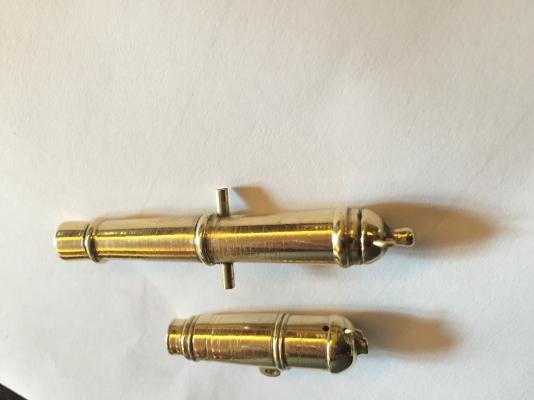


- 186 replies
-
- 11
-

-
Brig Eagle by robnbill - 1:48
robnbill replied to robnbill's topic in - Build logs for subjects built 1801 - 1850
Good luck Richard. Perhaps between the two of us we can develop a process and tool set. I did find there is a specific type of file that is recommended for brass that it supposed to sooth it well. It is a large file but I am thinking the sides can be used for the smaller areas and the larger might be able to smooth the barrels down. We will see, anyway, the the file has longer angles in a single direction and is designed for use with lathes. On Amazon it is Nicholson Long Angle Lathe Hand File, American Pattern, Single Cut, Rectangular, Fine, 10" Length . I ordered it and will let everyone know how it worked. I also played with my other files as well as my turning tools just to see how I could get the smoothest finish before I start the sanding and buffing process. I played with spindle speed. Some things you read say slower, others say as fast as you can turn. I found faster seemed like it worked a bit better. I also played with oils using WD40 and light machine oil. They both worked. The really great thing they did was kept the shavings collecting around the tool rather than slinging extra fine needles over half my shop. So that was very helpful. It might have also helped the chatter but that is too soon to tell. Reducing chatter seems to be directly related to finding the sweet spot for the angle of the cutter to the rod. This seems to be somewhere between the horizontal centerline of the brass and down slightly. Nothing above horizontal. The files chew brass off rapidly and they can be placed anywhere around the shape as long as great care is used to keep them away from the chuck. That would be very bad. I started spraying the files with WD40 to lubricate them. Otherwise they tended to get packed with the brass dust and would need a brush too clean. I know I thought I was going to move back to the ship and leave this a while but there is more experimentation I want to try with this before I do. I am fairly confident I can turn one Caronnade and one Long Gun, replicating them so they all look the same will be a new challenge. If this is too much for my meager skills, I may try casting them out of pewter per the TFFM. Good luck in your trials. Once we have our techniques down, we might want to start a thread just on this in one of the building techniques forums. -
When I was working on my Mamoli Constitution, I found I did not have enough of certain sizes to rig the ship in the manner I wanted, for these I purchased fantastic rope from Syren. However for the anchor hawsers I needed short lengths of very large line. For these I tried a rope walk that was on sale from Model Expo. It was cheap and an interesting very limited exercise. The rope walk was very inexpensive and broke almost as fast as I put it together but it server it's purpose - to teach me how they worked. My current ship is a scratch build of the Brig Eagle. For that, I do plan on using a ropewalk. Probably the Byrnes ropewalk but I plan on making a lot of line for this ship and ones after. That is just me. However, if ME does put their Rope walk on sale you might try it. It will teach you to appreciate ropes. You might also want to look at a simple serving machine. These can be built pretty simply and no one supplies served rope. That has to be made. Not all ropes are served but it does add a nice touch to your model if you serve those that are normally served.
-
Brig Eagle by robnbill - 1:48
robnbill replied to robnbill's topic in - Build logs for subjects built 1801 - 1850
Thanks. Richard, as far as tools, when I tried turning the small walnut carronade I realized my full size turning tools were way too large. I splurged on Easy Wood Mini turning tools. There are three, a roughing (square head), a smoothing (round head), and a detailed (diamond head). They are still a bit large but between them and some small metal files it seems to be a good combination. I chose the Easy Wood tools because they use replaceable carbide blades. This was my first time using these tools but they seems to work well. There is a real sweet spot that you have to find in placing the tool against the brass. Once I finished with the turning tools, I sharpened the detail edges with the small rifflers and metal files. Then used progressive sand paper to bring it down to almost smooth. Lastly, I have some finishing buffers I use on fine finishes like guitar backs. I could have buffed an even shinier appearance on the brass , but this was just a test. It will probably be a couple of weeks before I get back to the cannon. I need to come up with a draping method around my lathe. The large dust collection vent I use to catch wood shavings s I turn does not come close to catching the brass. The turning results in very fine brass needles flying off the tool. Nothing that can't be vacuumed up. -
Brig Eagle by robnbill - 1:48
robnbill replied to robnbill's topic in - Build logs for subjects built 1801 - 1850
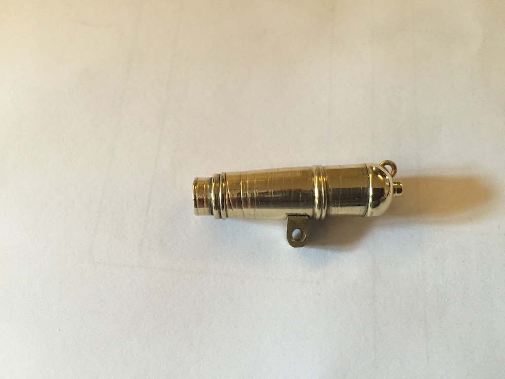
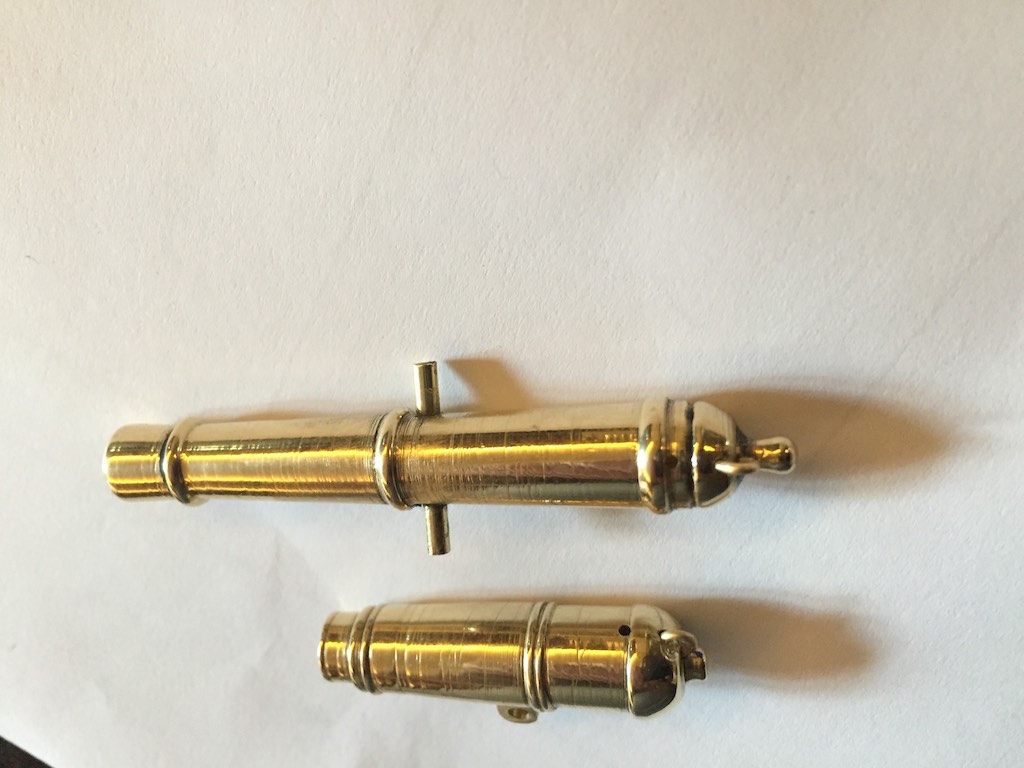
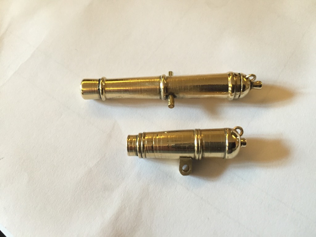
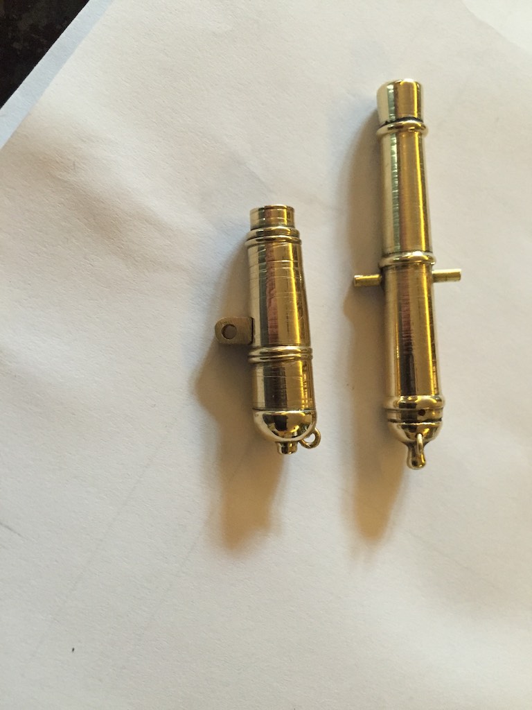
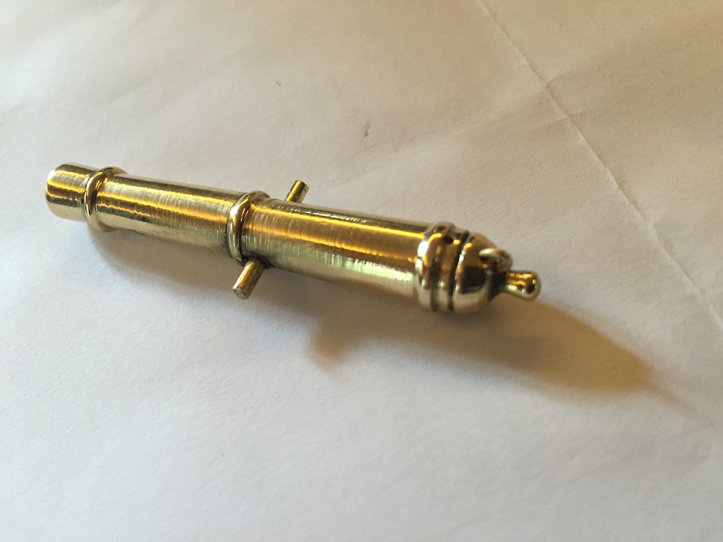
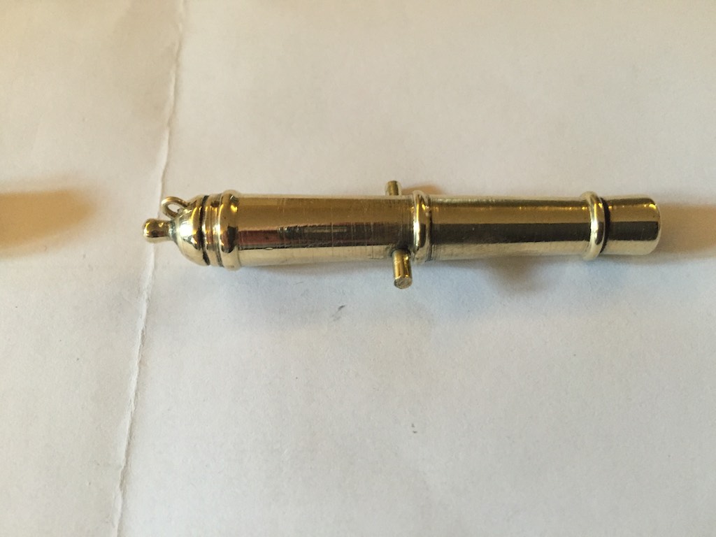
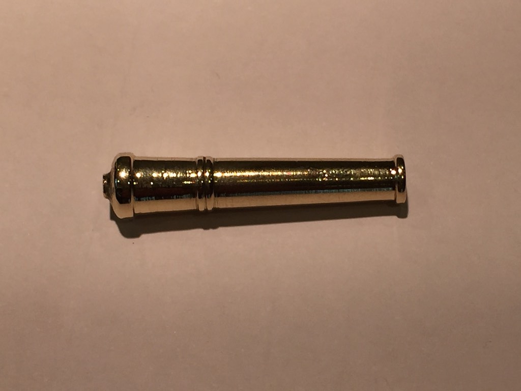
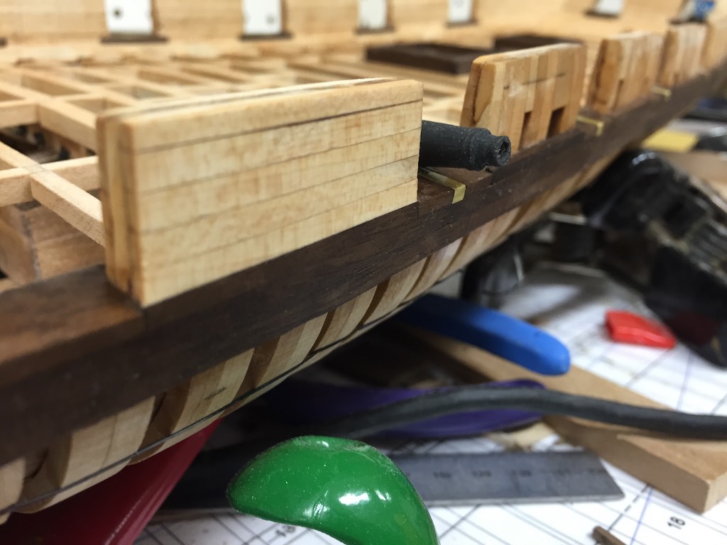
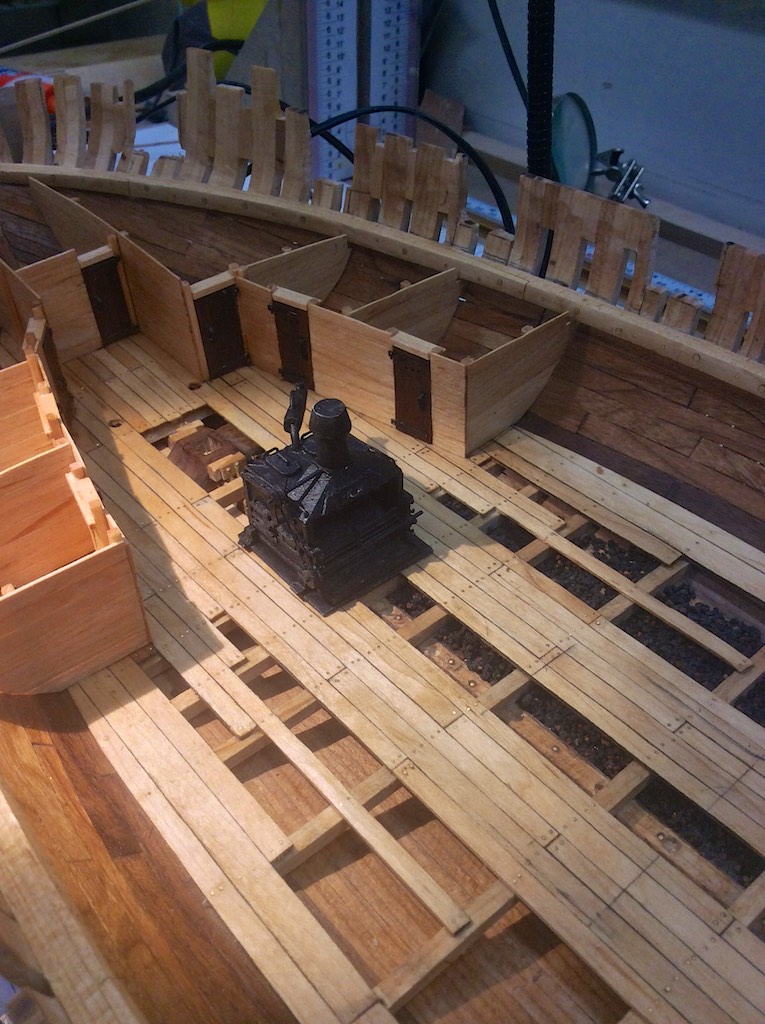
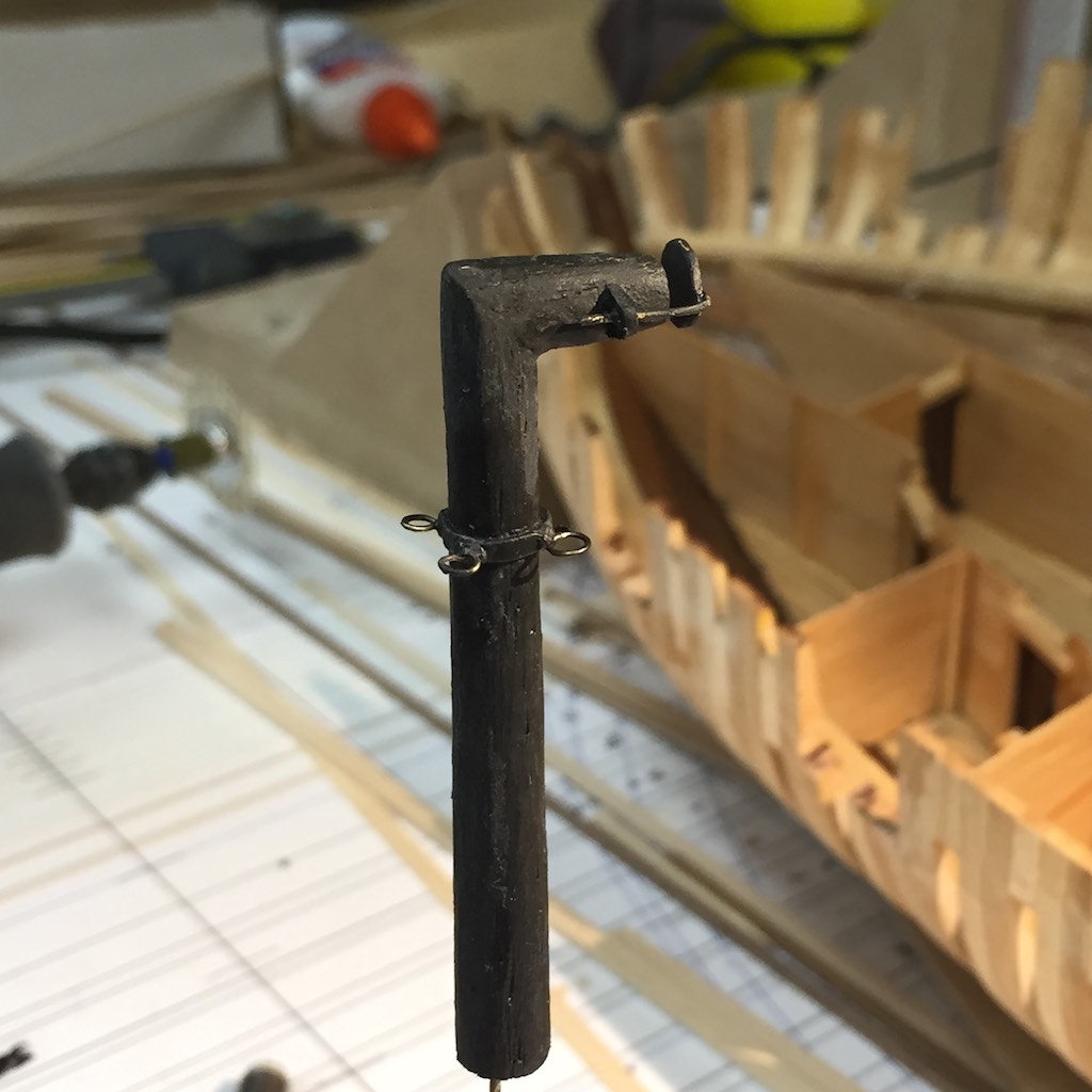
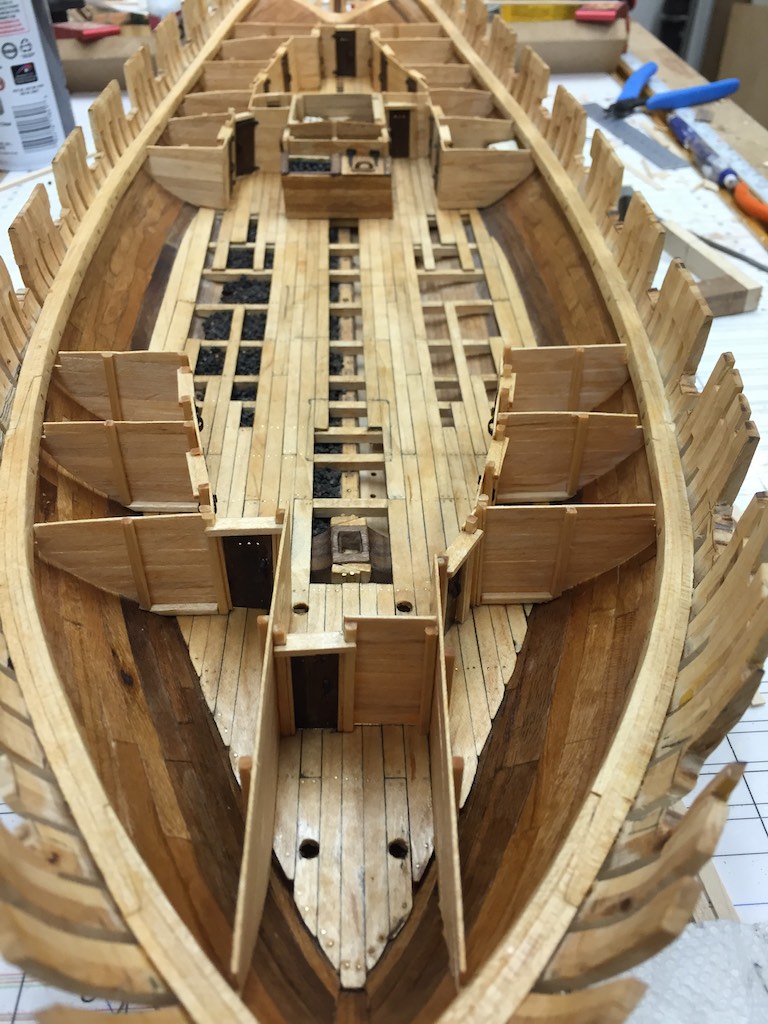
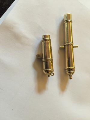
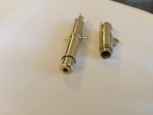
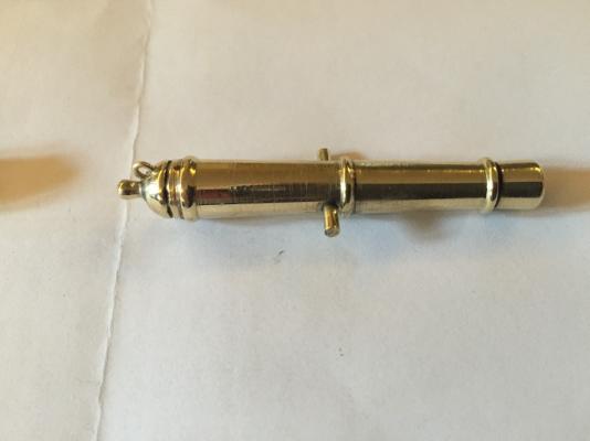
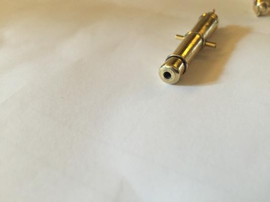
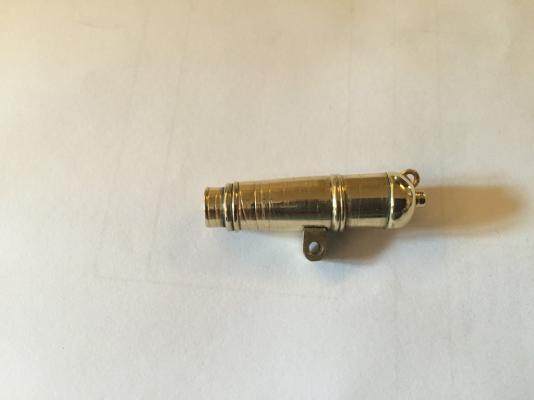
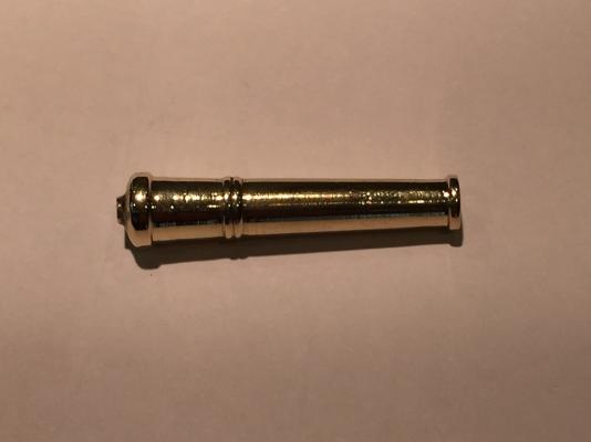
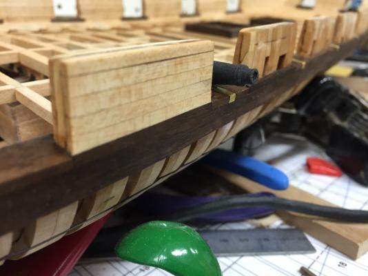
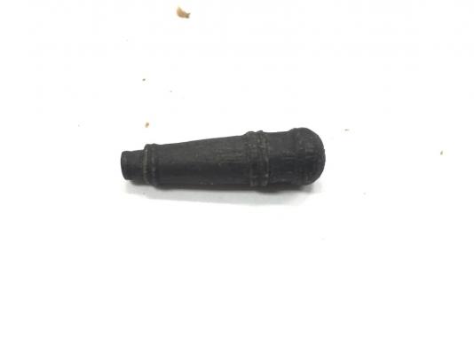
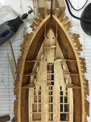
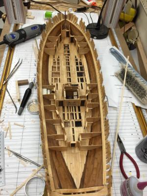
It has been several weeks so I wanted to give an update. After the last post I started working on the hatch coamings. I made these out of walnut. I also decided to make a modified hatch over the stove. Instead of building it into a solid cover, I made the coming then added the small plate that would be just around the Charlie Noble. I made this out of Walnut. The hole in it will be where the stack itself will be seated. This accomplishes a number of goals. It hides the connection for the stack to stove, and it still allows the stove to be seen below decks. After these were in place I tried to make the gratings. I wanted to have grating holes of 2 ½" ish. At scale this would be around 1.3mm. I tried to make these on my Proxxon (the entry level Proxxon) micro table saw. I was able to make gratings but totally unable to make consistent gratings. So I bit the bullet and ordered a Byrnes TS. So while waiting on that to come in, I proceeded to work on the planking. I started working on the inner bulwark planking. I did this in maple. Once all were done, I drilled and set all the brass pins to mimic the spikes. The wire size reflects a spike head of about ¾". After the inner bulwarks were completed I started working the outer planking. Other than the wales being thicker there is nothing regarding whether the wales were painted black or not. I decided to add wales using walnut. Above and below this I will us maple. Once the wales were in, I added the cannon port sills. These sit directly on top of the waterways. For those with the 32 pound carronades, there are plates inset in the sills with a hole the carronade carriage sits in to allow it to pivot. I made these out of brass and decided to leave them bright. Above the wales and sills, the outer planking is going to the maple. the top rails will be walnut. I have completed the port outer planking above the wales. As a break from planking, I tried some tests on the cannon barrels. I thought about turning them in Ebony, but almost assuredly, there would be some brown incursions in the wood unless I planned on wasting a great deal of wood to get the right black blanks, or I ebonized the wood. I decided if I used wood, I would ebonize using India Ink. This seems to be the thinnest finish that would produce a deep black that was still light safe so it would not fade over time. The alternative to that would be paint and I really did not want to paint the cannon. I did a test carronade out of walnut. I did not like the way it turned on that scale. It was just too course. While this could be overcome with the proper finishing (sanding and finish) I would rather use something like boxwood. The other alternative would be making them out of brass. There are a few sites (and one Youtube video) that show turning brass on a wood lathe. So nothing lost to try. I ordered some ⅜" brass stock and today tried to turn a barrel. This was just a test to see if I could turn a barrel with my tools. SO for this I did not use a pattern but turned a barrel similar to that of the long guns. It is about the correct size, but the goal here was just to see if I could do it. Then I would see if I could turn the correct pattern and replicate it. I am happy with the test turning. It was successful enough to go to the next step. Here are some photos of how she sits tonight. I spent the afternoon doing a bit of much needed shop cleanup. Next I will focus on completing the planking. The Byrnes saw came in and I can't wait to start using it! Here is the Wood Cannon followed by the Brass barrel.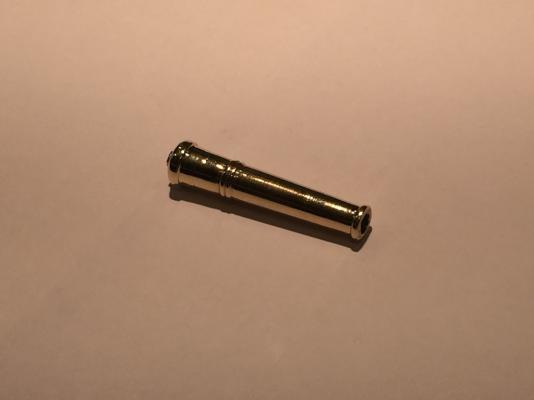


- 186 replies
-
- 10
-
-
Brig Eagle by robnbill - 1:48
robnbill replied to robnbill's topic in - Build logs for subjects built 1801 - 1850
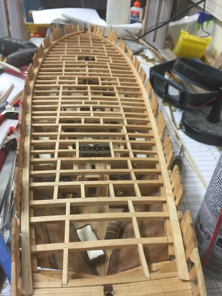
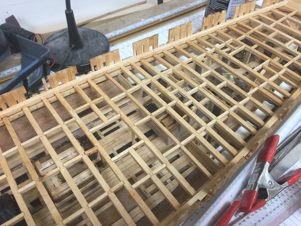
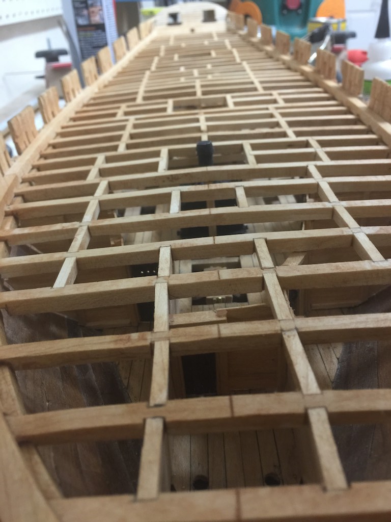
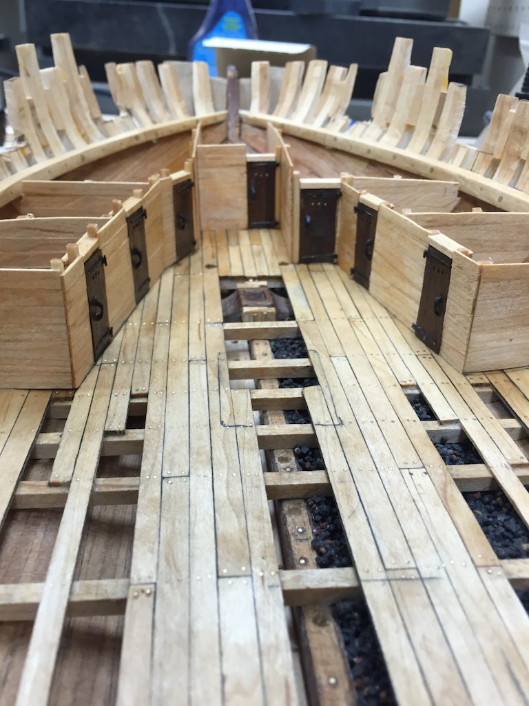
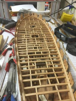
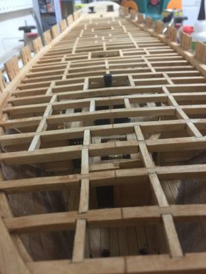
It has been a few weeks since I updated the log. The ship continues to take shape. I have completed the deck beams and added the waterways. I used a modified installation slightly different from Gene's practicum. I decided to notch the bottoms of the beams, but notch the waterway for the tops. I bent the wood for most of the waterway, but shaped the bow by cutting the shape out on the bandsaw. Once the waterway was fitted and notched, I shaped the sides to match the ships sides. I also tested cutting the cannonball cuts using small ball shaped diamond bits in the rotary tool. These seemed to work well. I will plan on adding the pins to the waterway once the cups are all cut. I still have some details on the berth deck that I need to clean up including the sail bin was a bit tall so it has been cut down. I need to redo the sails in the tops of the bin and finish up the cabins. I have been waiting to complete these until I decided how much decking to install. While I would like to leave half the ship open, I also would like to have cannon on each side. Decisions decisions...


- 186 replies
-
- 17
-
-
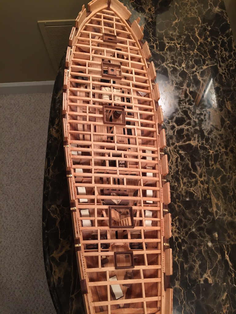
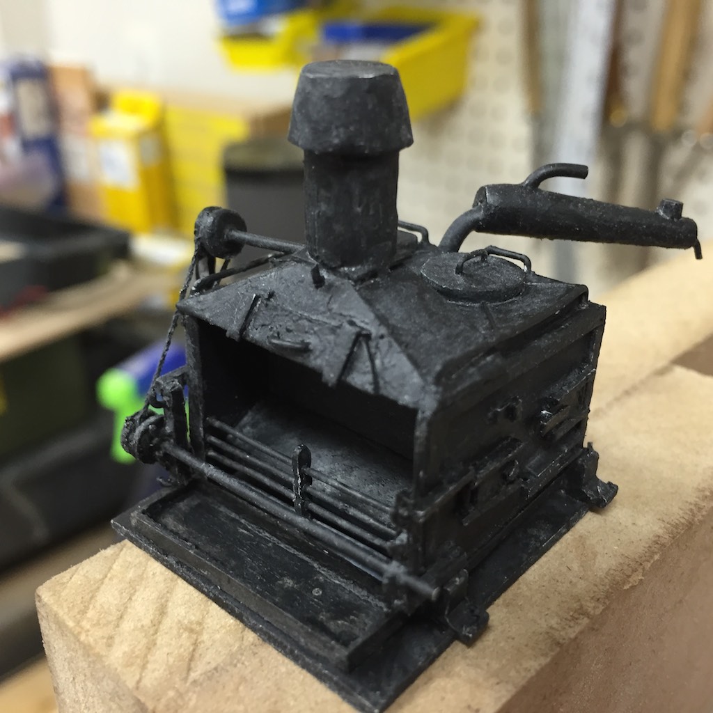
I tend to fall on the side of more detail with the very important rule that it must be in scale. It must look realistic to the scale and subject you are working on. I think a model should offer more than a viewer can take in. When I am adding a detail using a high magnification lens then bury it under additional layers of rigging etc, I do so knowing that it is there. The model is an illusion of the real thing. Just as a good illusionist is one who's performance does not break down when the viewer moves from the back row to the first row, my goal is for my ship's illusion experience to work as well. When someone looks at a model they start by seeing something obvious then following that down into details. They may start with a yard then follow that down to the lines controlling it, then the blocks controlling the lines, then how the line terminates on a pin rail and the coils of line looped over the pins. They should be able to picture a sailor coiling that line. A line, block or deck fitting that is out of scale will break the illusion. Then the viewer starts seeing the art of the modeler rather than feeling the illusion of looking into a ship. My goal is to provide and experience where the viewer runs out of the ability to focus on a detail because it is too small before they run out of details to see. Grabbing a magnifying glass should not break the illusion. Knowing what can be successfully accomplished in this endeavor is a challenge. When I built my Connie, there were details that would have been great to add but I could not either because the scale was too small, or my skills or materials were insufficient. A detail that cannot be executed well should not be on the ship. As some have said, you need to be consistent for size. If you get down to something that is 6" across then everything 6" or larger should be on the ship - except where it cannot be done without breaking the illusion of the model. Treenails have been mentioned. IMHO, treenails can be a very important detail or a (pun intended) nail in the model's coffin. Treenails, spikes, or rivets that are over scale, too few, or too obvious, make the viewer see the the art of the modeler rather than the illusion of the ship. On my current ship I use brass to represent the iron spikes used through out the ship. Luckily I have documentation on many of the sizes of spikes used in the various areas. There have been areas where the size of the spike causes it to disappear completely in the wood. When I had trouble finding where I put them using my magnifying headset I decided not to add them. These details were in the ceiling planks below the berth deck. It would be impossible to see them even with magnification. So they will not break the illusion not being there but would break it if I made them large enough to see. However, I am also guilty of adding detail that no one will probably ever see. These are put in because I want to. I enjoy challenging myself on learning to create the details that can make something come alive. I know I am not alone in this. How many of us have painstakingly added detail after detail on a Brodie Stove that is then buried under a deck and can barely be glimpsed through a grating? However if someone does get the correct light, and has eagle eyes, they will be able to see details and know that there are more to be seen. The illusion does not break before their ability to see the details does. Some have made reference to impressionist painters and our modeling ships. Recently I was lucky enough to go to the Van Gogh Museum in Amsterdam to see a huge collection of his paintings. His work gives the viewer the feelings he was experiencing looking at his subject. His "impressions" of the subject. The details are unimportant and indeed the illusion falls apart when viewing the paintings up close. There you can see the art of the painter when applying just the right colors in the right shape to make it look like a field of sun flowers when viewed from a distance. Van Gogh's genius is providing the viewer the ability to "feel" what he was feeling looking at the subject. No one would look at "Starry Night" and say that looks exactly like the view he saw out his asylum window in Saint-Rémy-de-Provence. It is not realistic nor meant to be. However we do feel the wonder and beauty he felt when looking to the stars from the fantastical manner he painted it. I posit ship modeling falls in the realism genre. I had the opportunity on the same trip to go through some of the finest examples of model ship building in the maritime museums in Amsterdam and Lisbon. The ships show amazing detail in scale. I did not get a sense of what the artist felt when he looked at the ship other than respect for the subject. Instead, the best models would make you feel like you were looking down at a ship from an omniscient perspective. You could see inside the ship's frames and move all around to appreciate the art of the ship's construction (notice I did not say the model's construction). My goal as a model builder is to give that to the viewer. I want them to see the ship and it's beautiful lines and the artwork of it's mechanics and appreciate the men that designed and built her - not the person who built the model.
- 55 replies
-
- 12
-
-
Brig Eagle by robnbill - 1:48
robnbill replied to robnbill's topic in - Build logs for subjects built 1801 - 1850
You re welcome. I know I have seen a number of pre Brodie stoves in the build logs. Not sure which ones off the top of my head, but there are some great examples that I have seen. -
Brig Eagle by robnbill - 1:48
robnbill replied to robnbill's topic in - Build logs for subjects built 1801 - 1850
Dave, the link from Mark is one of the sets I used. I also used information from the NRG paper by Allan Yedlinsky as well as an excellent article on the HMSFly.com site. The later had historical information including the scaling that the British Navy used on the stoves. I ended up using all this information and then made my own version. Bill -
Brig Eagle by robnbill - 1:48
robnbill replied to robnbill's topic in - Build logs for subjects built 1801 - 1850
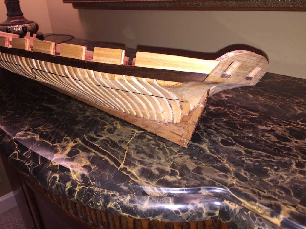
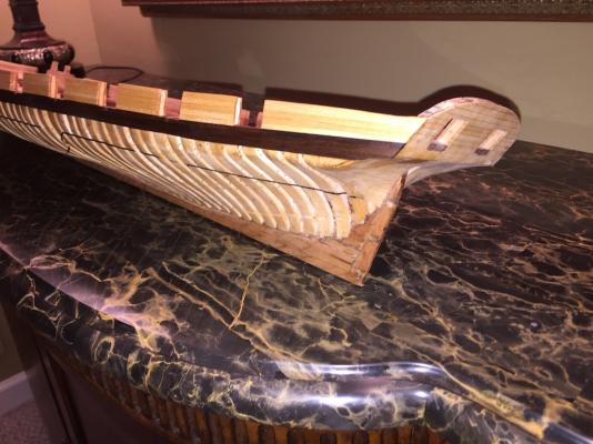
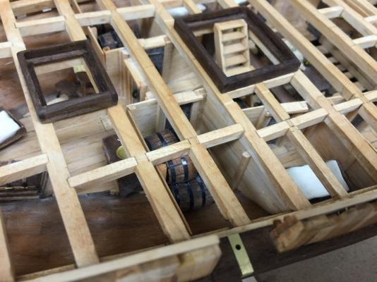
I thought I would give an update on the Eagle since it has been awhile since I did. I have pretty much completed the berth deck. There is still some additional furniture to add to the officers cabins, but other than that it is done. The three photos below show the sail bin. Next are the table and benches for the ward room. The map is a preproduction of a 1776 survey map done of the lake. The captain's cabin shown here. Later I removed the writing table for a simpler one and bench. The furnishings are the bed, chest of drawers and water basin stand, sea chest, and writing table and bench. The beds are all carved from maple and painted to look like straw mattresses. After these were done I started working on the barrels. I made two sizes, a few puncheons and a dozen hogsheads. These were based on the standard barrel measurements. I made these by turning a length of maple into the shapes. After cutting these apart I used the easychuck to hold them while a flattened and cut the inner top recesses. I cut the stave marks by holding these up to the scroll saw blade and the micro chisels to cut the tops. I painted these black then wiped and buffed them dry. Then a quick staining. After these dried I used the pin striping material and made the hoops. I placed these temporarily around the ship to see how they worked. I will glue these in just before I plank the main deck. The letter on the captain's writing desk is a reproduction of a letter from Captain MacDonough from the Navy Archives. I then turned my attention to the rudder. Dr. Crisman states that much care was taken in shaping the deadwood. I used the profiles from his book to shape the rudder. The pintle and gudgeons were made with brass. I planked the stern inside and out. I have cut the holes for the spikes. These will be the equivalent of ¾" spike heads. I completed installing the spikes in the upper outside of the stern. The holes are all drilled and the pins cut. Tomorrow I should complete these installation of these. Then I plan on working on the main deck beams and waterway. So that is where she stands tonight. I am pleased with how she is coming along. I still need to decide how much of the main deck I want to plank. I would like to have cannon on both sides, but that means more deck covered. I will decide this after the beams are installed.- 186 replies
-
- 19
-
-
Question about stoves and how the rotisserie worked
robnbill replied to Modeler12's topic in Nautical/Naval History
I think the proof they worked is in the widespread and continued use of them on land and in many galleys at sea. History shows numerous examples of genius apparatus that were built - one time. When they did not work, or were not efficient, they were discarded to the historical rubbish bin. It is very easy to to find examples of this spit on many different stoves over many years. In fact if I recall correctly there was a period where Connie had a side wheel installed. Why was Connie's changed out? I think as her roll changed she was modified to fit it. We also know from history most of the times she was refit, she was poorer afterwards. The downward spiral continued until she was almost scrapped. There is an excellent article on the Connie's stove and it's history on the restoration site. The link is below. Constitution Stove -
Workshop Set Up Question
robnbill replied to ChrisLBren's topic in Modeling tools and Workshop Equipment
That is an air handler. There are a number of manufacturers who all look basically the same. It is just a box with filters and a large fan to move the air through them. These type handle the dust that gets in the air. They do not take the place of your dust collector that would connect to the individual tools. The drop ceiling will be porous to the dust so some dust will migrate up through the ceiling and possibly into the spaces above it. I had the sheetrockers sheetrock that as well. I built the studs out for the shop but had the electrical contractor and sheetrocking guys do their stuff. That way it was also up to code. We insulated the outer walls and it makes a huge difference in temperature. I know because the network closet is also off the shop and it is not insulated and it get's cold in winter. -
Workshop Set Up Question
robnbill replied to ChrisLBren's topic in Modeling tools and Workshop Equipment
My shop is in my basement. It actually is buried deep in the basement. We have a walk out basement, but the only place the shop could be is in the front of the basement. Because of this, when we installed it, I put in two over sized dust control systems. I have a large 3.5HP cyclone that handles dust down to .5 microns. The cyclone is piped to each of the major tools as well as floor sweeps. Then I have two air handlers that are suspended from the ceiling at either end of the shop. These recycle air through filter material so pull dust created by sanding or thrown from the blades and did not go through the cyclone. I still make a lot of dust, but it does seem to keep most of it from circulating into the rest of the house. -
Brig Eagle by robnbill - 1:48
robnbill replied to robnbill's topic in - Build logs for subjects built 1801 - 1850
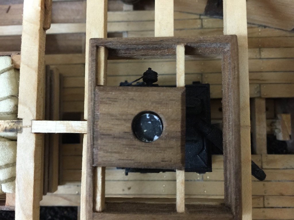
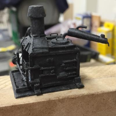
I worked on the Brodie Stove and Charlie Noble today. I made it out of maple and brass. It was a fun project. I know the details of this will not be seen once it is installed in the ship, but I know they will be there. I will install the Charlie Noble once the main deck is in.


- 186 replies
-
- 15
-
-
Brig Eagle by robnbill - 1:48
robnbill replied to robnbill's topic in - Build logs for subjects built 1801 - 1850
Thanks Tim. The deck above it will certainly obstruct some. I have to work out how much I cover and how much is left open. I am hoping that once I start working on the main deck beams I will be able to figure out how much will be obstructed. I will not be fully planking the main deck, so I do have some control. If I fully plank beneath the cannons it would cover up nearly all of the cabins so I will need to be creative in how I approach the planking on the main deck. -
Brig Eagle by robnbill - 1:48
robnbill replied to robnbill's topic in - Build logs for subjects built 1801 - 1850
I have completed framing in the cabin walls and doors on the ship. Still to be done on this deck are the sail bin, the Brodie Stove, and the various accouterments for the cabins. I still need to do some research for the various storage rooms. Typically there would be one for each of the Carpenter, Gunner and, Boatswain. Since the Eagle was on a fresh water lake, there was no need to have large storage areas for water, however, food, armaments, and rigging were still required to run the ship.

- 186 replies
-
- 10
-
-
Micro-Mark MicroLux LaserKnife 2525 – A Review
robnbill replied to mtaylor's topic in Modeling tools and Workshop Equipment
Very interesting Mark. Thanks for reviewing this. -
The cost is comparable to other saws of it's type. It is a damn good table saw on it's own. I really have enjoyed using it. Having a good, well tuned table saw and a sharp blade makes a world of difference.
-
That is the reason I upgraded my table saw to a SawStop. I hope never to test it, but I think it still provides more margin of safety than any other saw out there.