robnbill
-
Posts
841 -
Joined
-
Last visited
Content Type
Profiles
Forums
Gallery
Events
Everything posted by robnbill
-
 Congrats on a beautiful model. She looks as proud as the real Connie (although yours currently has more rigging!). What's next?
- 732 replies
-
- 1
-

-
- constitution
- model shipways
- (and 1 more)
-
Brig Eagle by robnbill - 1:48
robnbill replied to robnbill's topic in - Build logs for subjects built 1801 - 1850
I think you will find that DeltaCAD is a pretty easy system to learn. Once you do, you will be amazed at what you can do. I have used it from designing and making a roll top desk, to the platform for theater seats in our home theater. When I was building the Connie, I used it to take the line drawings from the AOS and make them into fully fledged build drawings at the Mamoli scale. -
Well Joe, it looks like you are going to have to attend the NRG Conference in the fall. See your next build up close and personal.
-
Brig Eagle by robnbill - 1:48
robnbill replied to robnbill's topic in - Build logs for subjects built 1801 - 1850
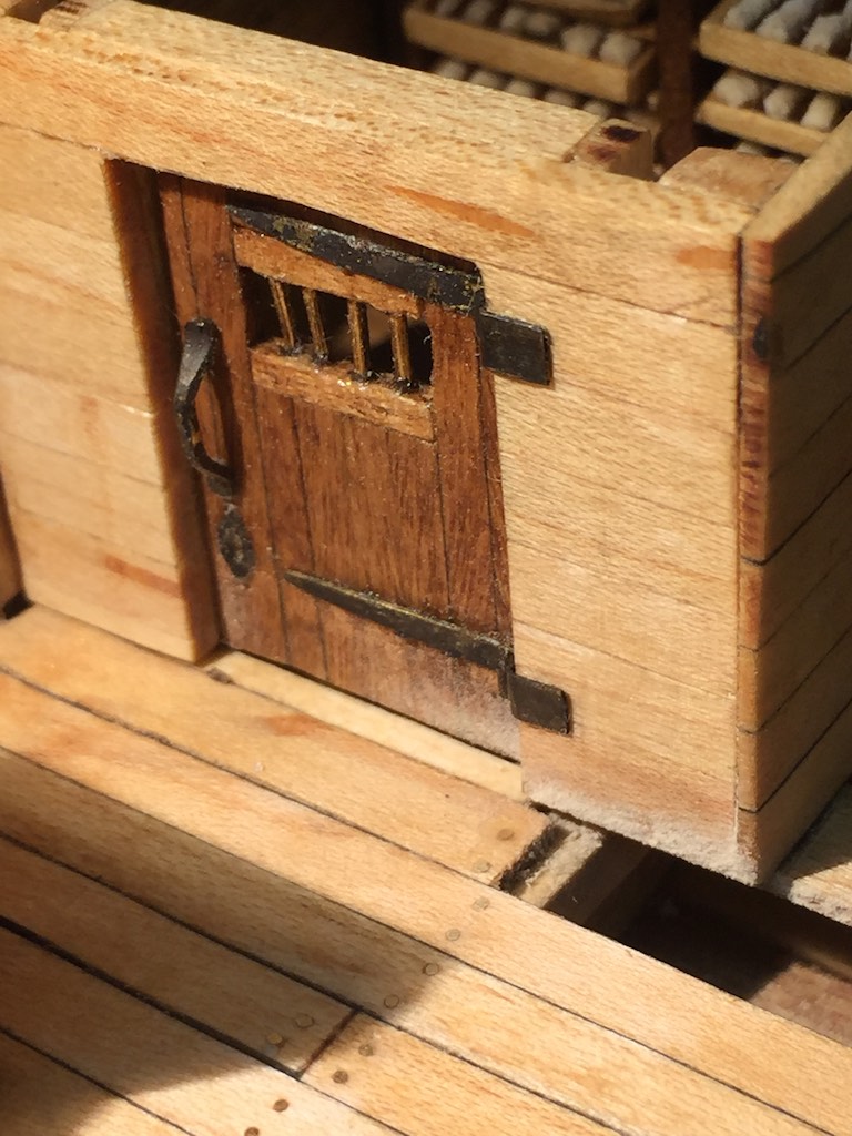
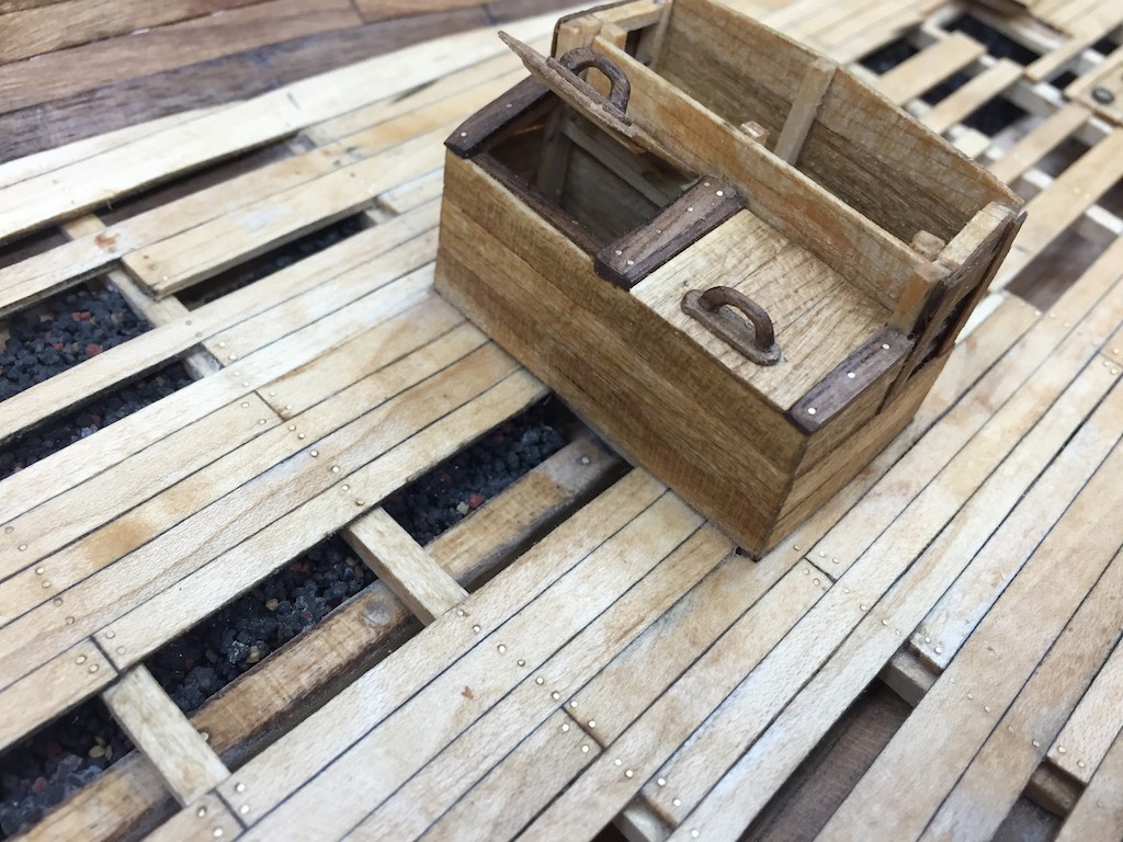
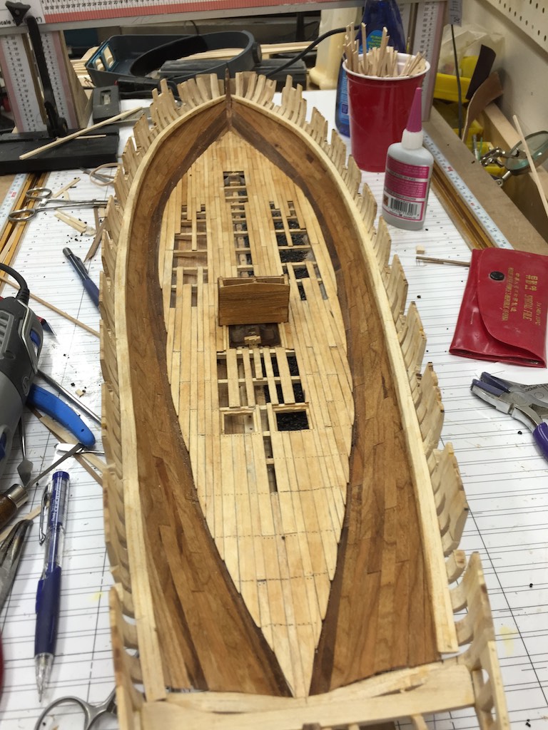
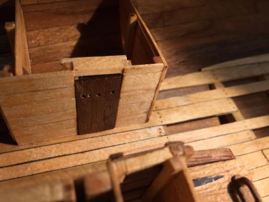
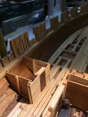
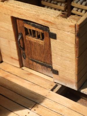
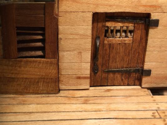
I have been working on a number of fronts since the last update. I built out the Midshipmen's cabin. This allowed me to work out the specifics on how I was going to build out all the cabins. While each cabin is unique, they will still be similar in what will need to be built. While there were three midshipmen on the Eagle's partial roster listing, there could have been four. Either way, they would have all probably bunked in the same room. However given the smallness of the space, I only provided two bed spaces. They would probably have hot bunked (at least on my version) since at least one would have been on watch at any given time. I put in a small chest of drawers and a washstand. I formed the wash basin by punching brass down into the center of a steel washer with a large punch. Then I would cut the outer rim out of the square and use the rotary tool to finish shaping. I made enough basins for each of the officers cabins. I spent some time working on a suitable mattress for the beds. The officers would have had straw mattresses. I finally carved mattresses and painted them. This keeps from having too course of fabric for the scale and keeps the soft materials out of the model. After I finished the cabin, then I started work on the next one aft, including the doorway to the officer's wardroom. The ship had 5 ½ feet of headspace which was actually more than other ships of the time such as the Peacock (4.5 feet). The doors still end up being about 4 ½ feet tall. While this seems very short, it was not. In Sydney a few years ago, I went aboard the replica of the Endeavor. I actually had to get down on my hands and knees to get to the captain's cabin and could not stand totally straight once I got in there. These guys were not claustrophobic! Imagine having a full crew, provisions, and gear crammed into those spaces and living like that for months if not years at a time. Once I had all the cabin walls installed I spent time making all the doors needed for the remainder of the berth deck spaces. I do not plan on building out the interior of the remaining cabins until all the walls and doors are in place. Here are two shots of the door to the wardroom almost ready for installation. And here is the same door installed looking each way. Doors are ready. Now I just have to frame the walls in and make the hardware for them. Here are two shots showing the two cabins currently done. The midshipmen's cabin is complete.- 186 replies
-
- 13
-
-
Brig Eagle by robnbill - 1:48
robnbill replied to robnbill's topic in - Build logs for subjects built 1801 - 1850
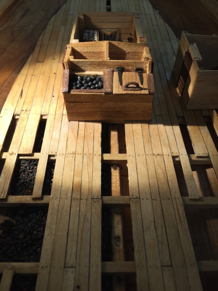
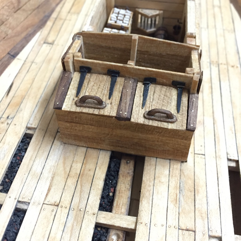
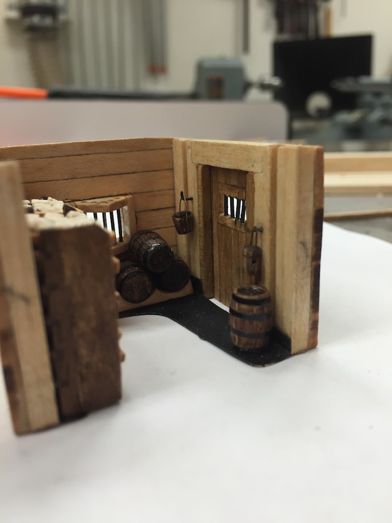
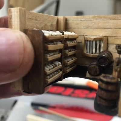
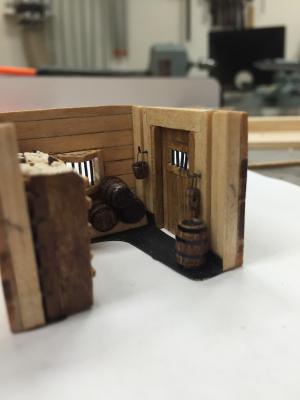
I have started work on the cabins by building the magazine since it is central to the ship. This is a very busy room and normally a very secure room. However in this ship, there is no room to have a remote magazine. So based upon all the materials I placed it just behind the pump well. While the ship was built quickly, care of the powder would have been paramount so I spent some time accessorizing the magazine. I used a blackened brass plate to mimic the lead flooring and cut it out so the area beneath the magazine would be visible. According to the TFFM a keg of powder would be 19" tall by 15" wide. At scale this would be 10mm x 8mm. I used oak dowel to turn the kegs. Once turned I cut slots in the sides with a scalpel to show the staves and black pin striping to make the hoops. I also used the dowel to make a bucket and passing box to hang on either side of the door. I created a light window that would be accessed from the officers wardroom. I used slide covers to cut glass for the light cupboard glazing. I made racks to go along the starboard side to store the cartridge trays. Each of the 10 trays was built as a shallow tray with 5 separators and would hold 18 cartridges each. Since the cartridges were hand sewn on the ship I wanted them to look to be of similar size, but to not be cookie cutters of each other since each cloth cartridge would look slightly different from handling. I finally figured out a method for cutting thin strips of the same fabric I used for my Connie's hammocks. This was a paper cloth that I stained with tea and coffee to be slightly tan. I would take a thin strip and run a line of thick CA down the length. Then I twisted the strip into a cylinder. I would finish it by using a bit more CA and using it to make the cylinder consistent. Once it was dried, I cut them to length with the scalpels. I placed these three to a slot in each of the trays and once filled, glued the trays into the rack and the filled rack into the magazine. Once the interior was complete, I added shutters to the outside of the light cupboard and hardware for the door. After this was all complete I glued it into the ship. I stained the first set of cannonballs. I am using chrome ball bearings for these. I have found by heating these red hot with a torch then soaking them in blackening solution. Once stained I used them to fill the starboard shot locker. I filled most of the locker with a block of wood and some extra ballast (suitably glued with CA to make solid). Then I glued the newly stained cannon balls into the top. The lid of this side will be open but will not be glued in until later in the build otherwise it would be easy to break off. I started working on the cabins with the midshipmen's cabin on the port side. This one took a bit of time since I had to work out the joinery to be used in the cabins. I will build the furniture into the cabins once more of the cabins have their bulkheads are completed. The door to the cabin is just sitting in the frame. I think I will change the ventilation holes. They need to be higher and closer together on the door. Once satisfied I will add the hardware to hold the door.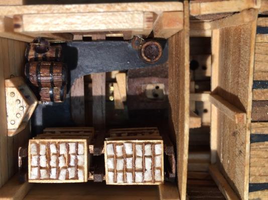


- 186 replies
-
- 18
-
-
Okay, I also purchased the Dremel 4000. In sanding the interior of the Eagle, I was putting the Foredom tool into kinks which caused the tool to operate a bit jumpy. So I purchased the Dremel for those areas. I have to say, I like it a lot as well. So put me down for promoting both tools!
-
Brig Eagle by robnbill - 1:48
robnbill replied to robnbill's topic in - Build logs for subjects built 1801 - 1850
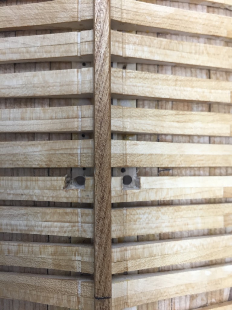
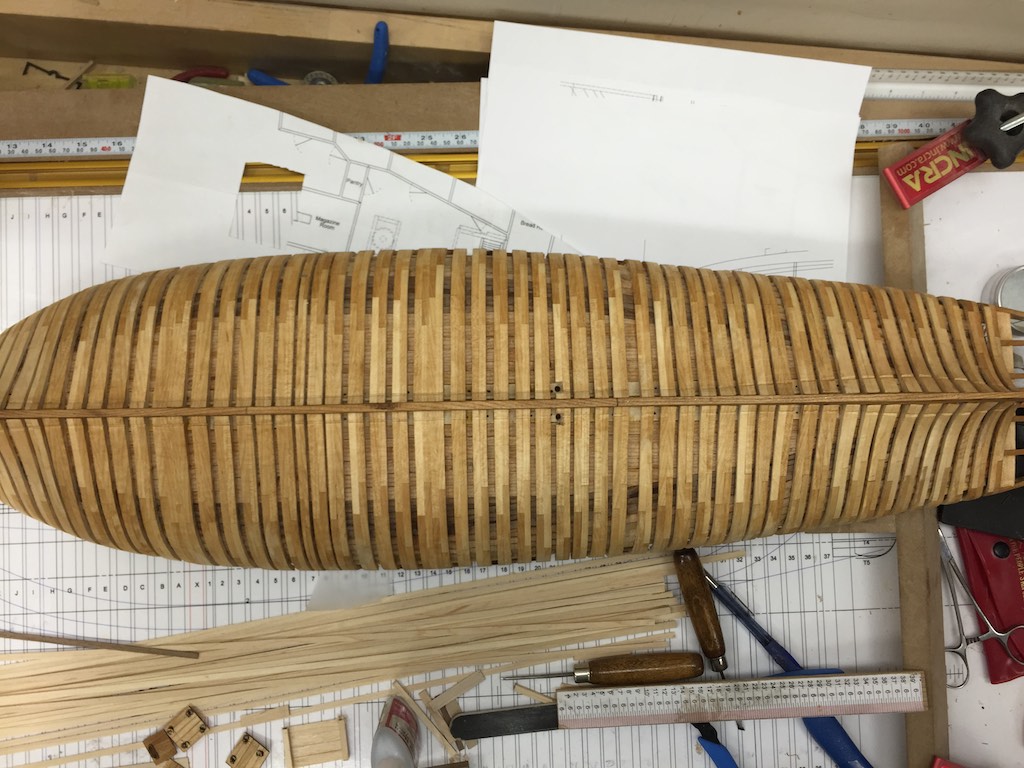
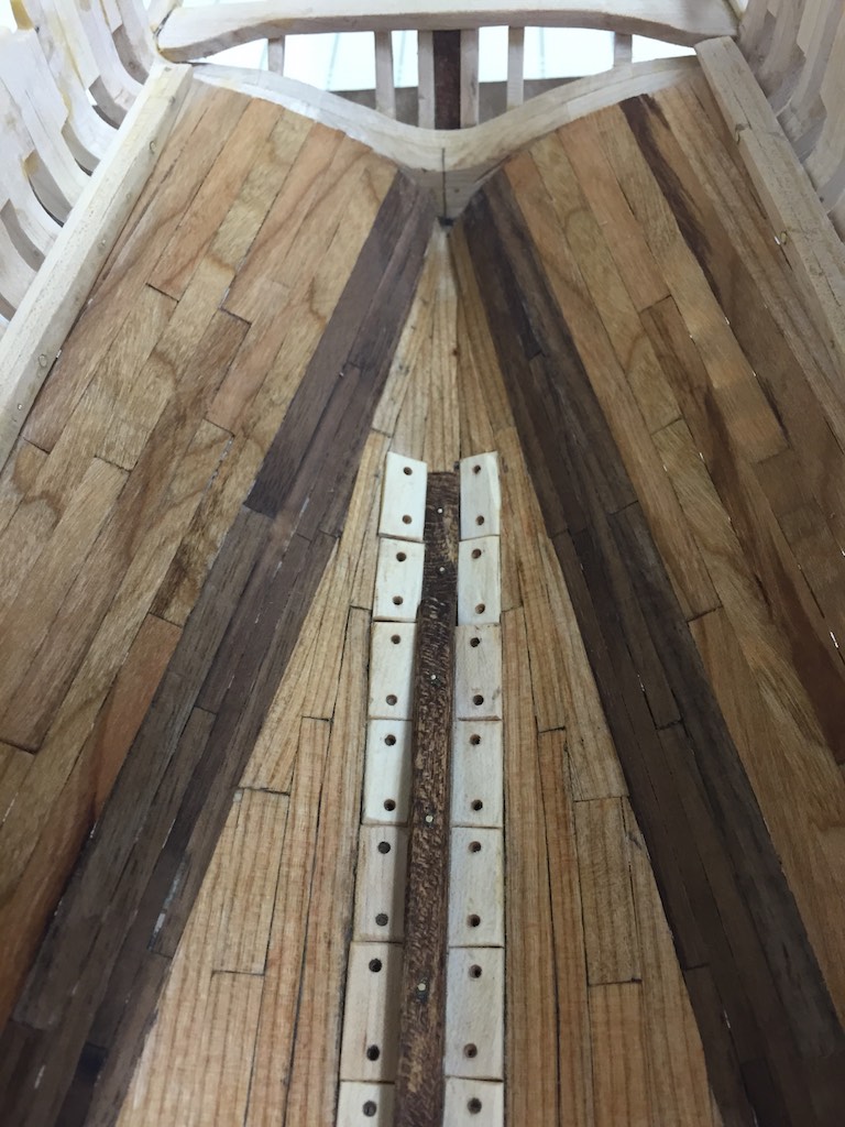
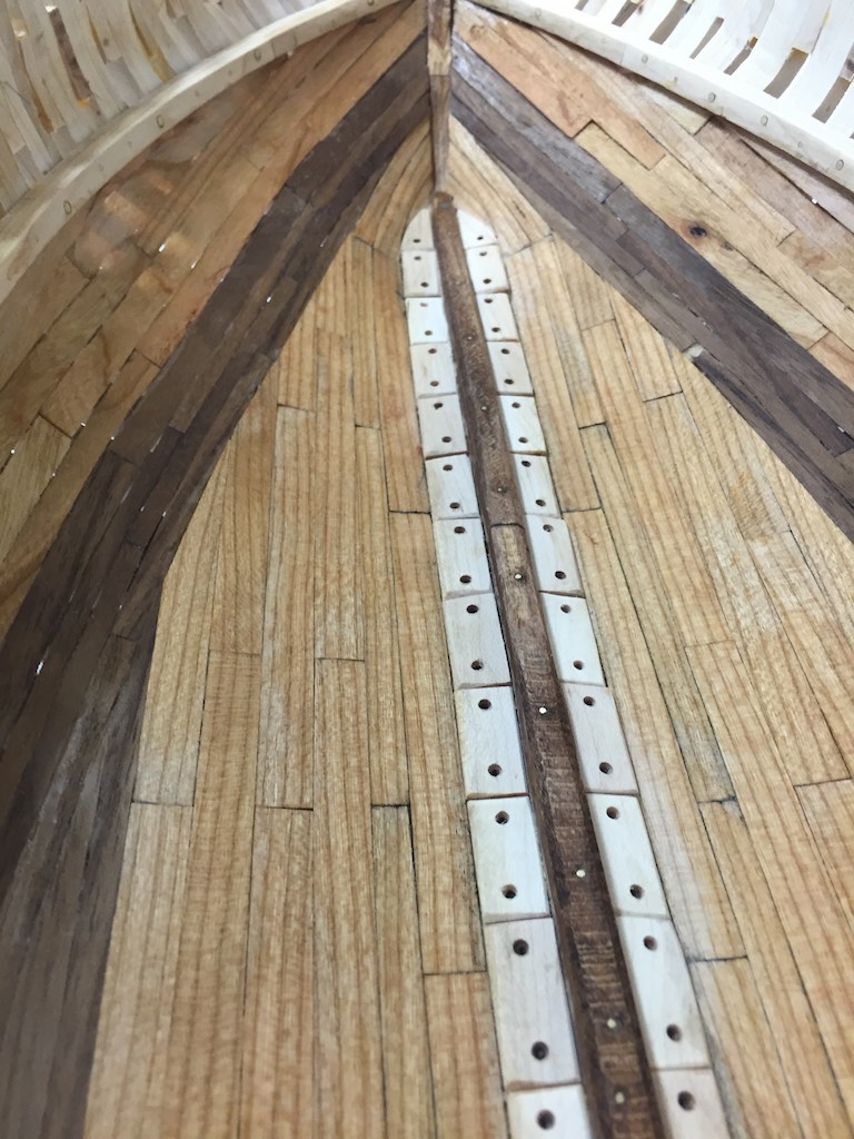
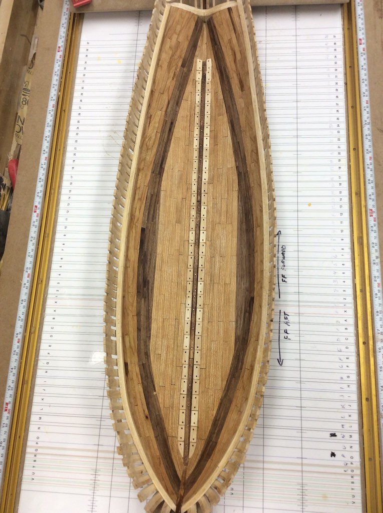
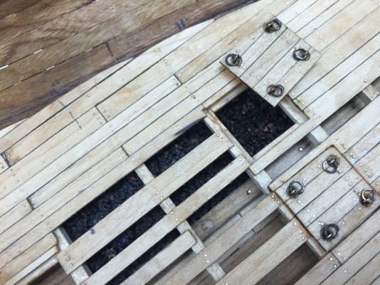
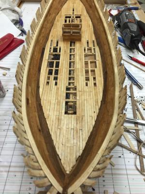
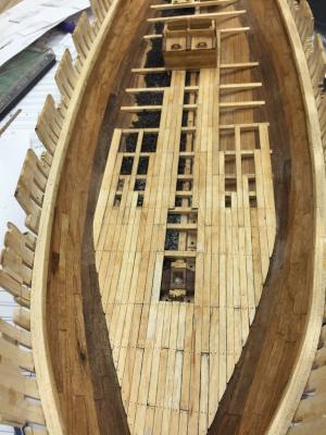
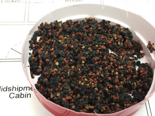
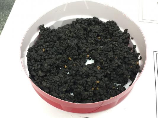
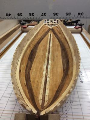
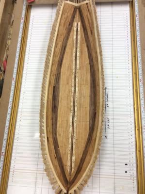
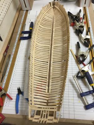
I have been focusing on the berth deck construction. After all the deck beams were installed I faired them then started working on the shot locker and pump well. I decided to follow convention and build these as a single unit. I plan on having one of the locker doors open to show cannon balls within. I have not attached the hardware for the hinges yet. Once this was done and the main deck stanchions locations marked I was ready for the next step. Installing ballast. The ballast for the Eagle is known from the records of the ship. They used magnetite ore. It was cheap and readily available and easy to use balance the rig quickly. Once the ship was launched they moved it down river toward the lake. Once they were past the last shallow bar, they added the ballast. There was very little room between the berth deck and the ceiling. Once the ballast was installed there was little to no room for any additional storage. I used model railroad ballast and tested a number of different mixtures. I decided on using the black ballast with a small amount of the iron ore and tan to mix in it for depth. After a couple of tests with glue I mixed 50/50 white glue and water with the mixture and spooned it into the ship. I only added it to one side wanting to show the difference between the ceiling planks on one side and the ballasted ship on the other. Next I started on the deck planking. I used the maple to make the deck strips. I plan on using the cherry and walnut for furniture and details in the cabins. To assess where I wanted to plank I printed out the deck layouts for the cabins and placed this in the hull. Eagle models tend to fall into two categories. There is the kit version which is POB and not very accurate, and the POF models that tend to show very little of the below deck structures. I wanted to provide enough planking to show off the cabins and give the feel of the ship while still leaving enough open to allow the structure of the ship to show. So this is a balance I will be seeking though out the build. I decided to plank the bow and stern fully leaving openings above the keelson where the stanchions attach as well as providing enough planking for the stove and other deck fittings. Once the planking was installed I used a #75 drill to drill the holes for the pins. This would equate to a 1" diameter circle. Still slightly large since these were iron spikes and probably ¾" at the head, but testing showed anything smaller would not show at all. Leaving these brass shows the spikes but does not overpower the planks. Once the deck was pinned and sanded I rubbed the entire ship down with the light stain. This enhances the wood and the joinery. I do not plan on adding anything more to make it darker. I will do clear coat once the ship is done. This was the test of the ballast. The mixture was too varied here and the black too black. I added enough of the colors to add depth and interest in the hold when seeing the ballast. Below is the hull once the light stain was applied. The notches below are for the lower ends of the pumps (and below the well). The linear notches running either side are the limber holes feeding the well. Here is a close up of the shot locker and pump well. You can also see the pinning. Still some dust from all the sanding showing. This shows the differences between the ballasted side and the ceiling side. The small circle on the keelson will be the seating point for the windlass stanchion. Here I have started the forward deck planking. Here is the completed planking. Now I wills start on the cabins.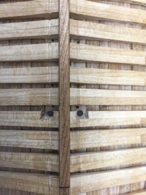


- 186 replies
-
- 14
-
-
Brig Eagle by robnbill - 1:48
robnbill replied to robnbill's topic in - Build logs for subjects built 1801 - 1850
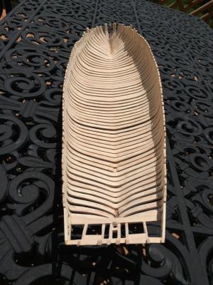
Posted: Sun May 24 2015, 02:44PM Since adding the ceiling planks I have focused on getting the outside of the frames and keel done other than planking the wales up which will be done later. So I worked on finishing the frame fairing on the outside, then doing the inlays of the butterfly plates on the keel. I also spent some time doing the final sanding and backing off most of the stain. As a result, the stain remaining left the keel with a nice patina and shows the joinery. Once that was done I turned the focus back on the interior. As I mentioned earlier I planed on modifying the mast steps to be more in line with the TFFM. This type of step would have been adjustable while providing more strength in the step. This also falls in line with the bolt patterns found in the wreck. So it is entirely possible it was done something like this. Once the steps were installed I started mounting the berth deck beams. I decided to install more beams than the practicum. This because I will be installing bulkheads and partitioning the deck for the compartments Crisman discusses in the materials. Since the deck would need to be stable for all the crew and supplies this meant more beams. Once these were installed I added the supports necessary to hold the shot locker and pump well. Due to the weight of the shot and the lightness of the deck beams, the shot locker needs support from the keel up. I added two longitudinal beams under the edges of the locker. I also wanted to add scuttle hatches for access to the space under the deck. Since there is no room forward, I added two in the stern area that would be just forward of the aft stairs. I made these by notching in angled carlings and notching the beams to provide a coaming around the hatches. Once installed they will be flush with the deck. I counter sunk the eye rings also in line with the TFFM. Once all were in, I applied a light stain from the clamps down to the keelson of Minwax Golden Pecan. This is the same I used on the decking of my Connie. I found it provides a nice tone and pops without overly darkening the wood. I also picked up some Model Railroad ballast. I want to use this to show how the magnetite ore was placed in the hull for ballast. I will do some experimentation with both the mix of colors and glue before applying to the model. My nerxt focus will be on the Shot locker and pump well.- 186 replies
-
- 15
-
-
Brig Eagle by robnbill - 1:48
robnbill replied to robnbill's topic in - Build logs for subjects built 1801 - 1850
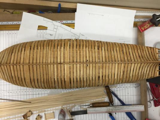
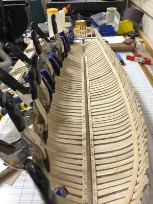
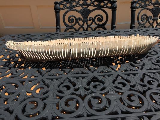
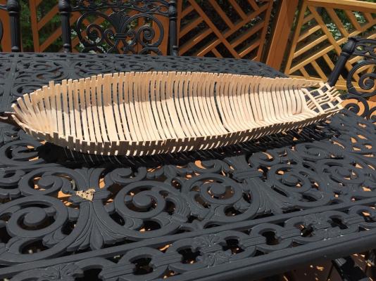
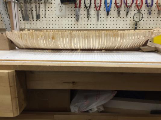
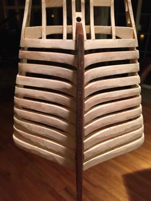
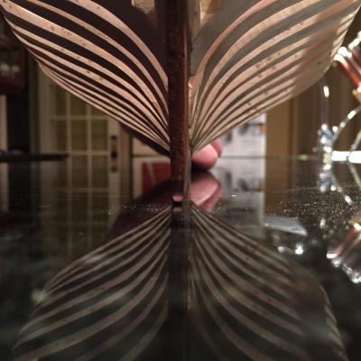
I have been working on the ceiling planking over the last few days. The jigs I acquired for my table saw make cutting strips to be as easy (and safe) as I could ask for. I cut up a bunch of strips in various widths and thicknesses based upon the Crisman materials. There are three bands of ceiling planks below the clamp. Those closest to the limber boards are described as wide thin pine or spruce. Next comes thicker oak for those around where the bend in the sides occurs and where the berth deck beams are attached. Lastly come spruce or pine boards again up to the clamp. I decided to use unstained cherry for the spruce/pine bands and walnut for the oak. This would give me some nice contrast. I have been minimizing the use of CA other than setting the pins in the planks but for this I found it to be required. Since the lower side of the ceiling planks will be visible through the frames, any squeeze out of the yellow glue would look bad. The CA stayed clear when dry so this was used. The upside of this is I also was able to use my planking bending iron to set the planks making the operation move much faster. Once the planks were all in place, I sanded everything down smooth then wiped the ship down with mineral spirits to remove the dust. The wood will lighten from that shown in the photos as this dries, but it does show what it will look like with a bit of clear coat. The photos below show the ship as she sits tonight. I was happy to see that from the side, planking the ceiling fully really doesn't affect the look much. Tomorrow I will work on the pins/spikes used to attach the planks to the frames.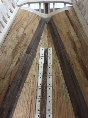


- 186 replies
-
- 12
-
-
I found that heating the balls to red hot and cooling allowed them to be stained black with the Blackening solution. Otherwise the chrome balls just wouldn't react to the chemicals.
- 1,354 replies
-
- 2
-
-
- constitution
- model shipways
- (and 1 more)
-
Brig Eagle by robnbill - 1:48
robnbill replied to robnbill's topic in - Build logs for subjects built 1801 - 1850
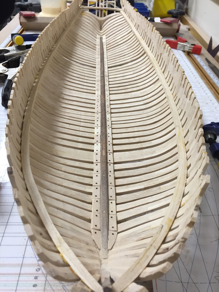
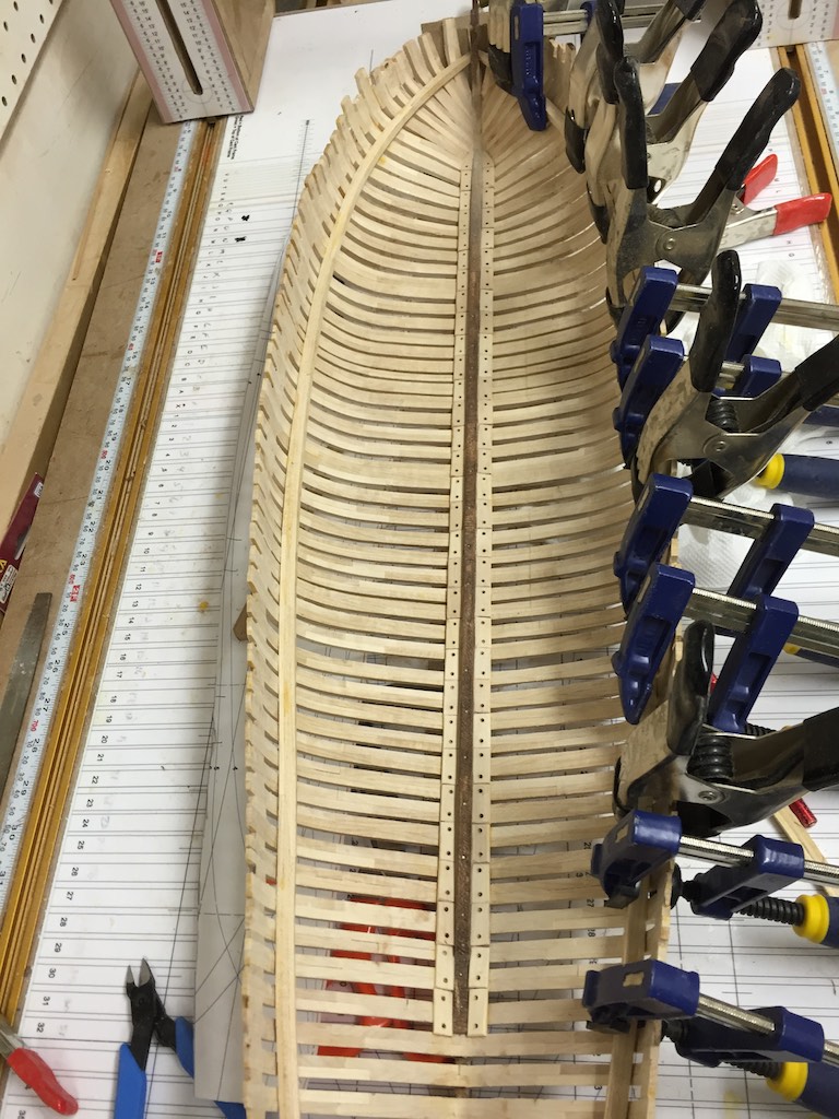
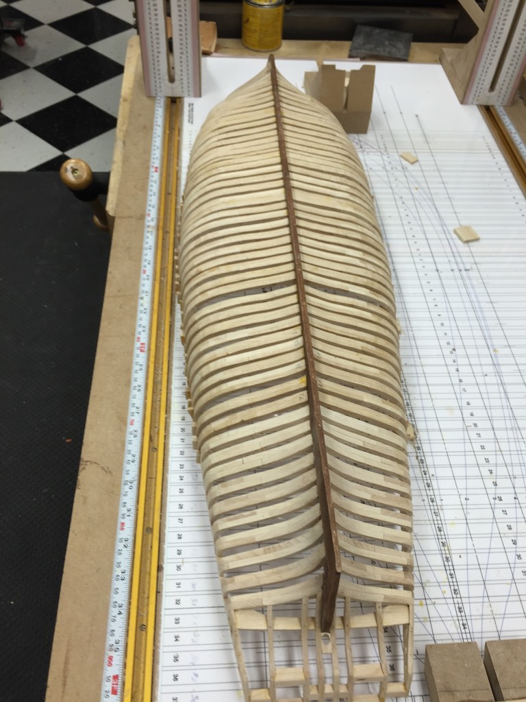
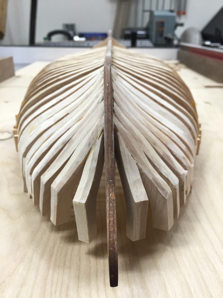
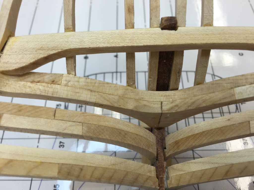
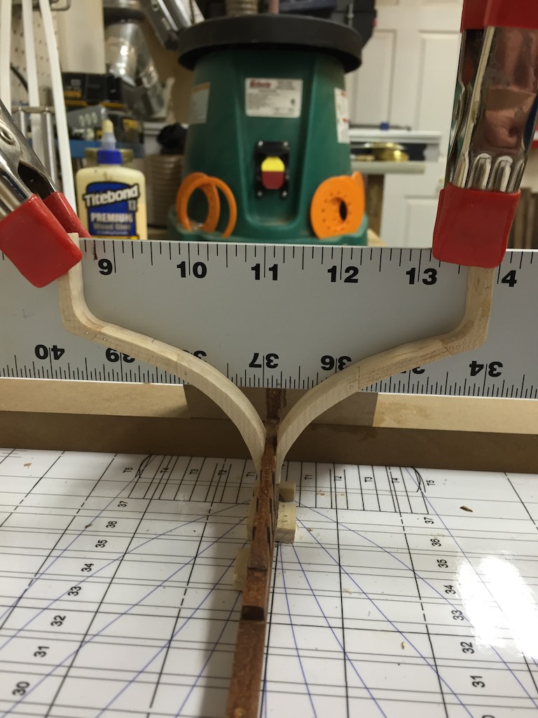
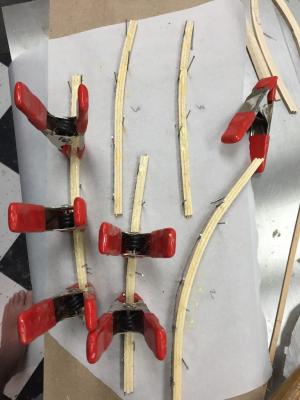
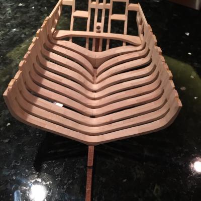
She is beginning to show her lines. I was able to create the keelson based upon the materials in the books. Once this was completed, I glued it into the ship and pinned it to the keel. The pins were scaled to 1 ½" and per the materials pinned every other frame through the floor. I have been perusing the Fully Framed Model for details in the berth deck. One of the items that was discussed as part of the ship but nothing recovered of was the Limber Boards. The space was there but nothing left. Since these were not attached to the ship, they could have been removed prior to the ship going into ordinary, or they could have floated off after she sank. The boards were generally around 3 feet long and we know from the wreck they were 15" wide. I attached a small 1x1 strip along the base of the keelson to attache the edge of the limber boards to. This kept them directly off the frames. After these were all installed, I moved onto the clamps. I assembled the clamps by cutting strips of maple. Three of each would be needed to make each clamp section. There were five sections in each clamp joined by a scarf joint. The lengths of these sections were provided by Dr Crisman. Each section was laminated and curved based upon the ships curves. Once each section was dried, I would cut the scarf joint and glue the sections together. Working from the bow alternating each side until reaching the stern. Once the clamps were fully assembled, I fit them to the sides of the ship, again starting at the bow and working aft. Once a side was fully fitted, I would glue it in place and go to the other side. Tomorrow I will add the pins to the clamps then start working on the ceilings.

-
Brig Eagle by robnbill - 1:48
robnbill replied to robnbill's topic in - Build logs for subjects built 1801 - 1850
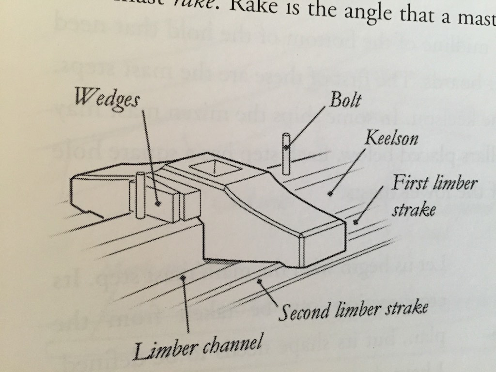
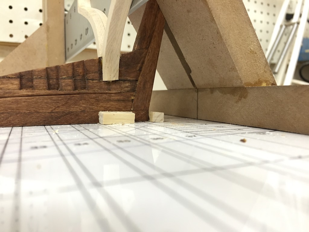
Most of the fairing is complete. The interior is done. The exterior is close. I will finish the exterior once the interior is a bit further along with the Keelson, clamp and ceilings. I have decided to fully plank the ceiling. Since I am going to install as much of the interior configuration as can be seen, this will provide a better backdrop. The frames will still be seen from the outside below the wales. Once the interior ceiling is complete, I plan on trimming the tops of the frames and cutting in the cannon ports. Final fairing of the sides will be done at that time. I also have been looking at the mast steps. In the supporting material, Dr. Crisman states that the step was about 3 feet square. I have been looking at configurations that would allow this since just extending the sides of a block would not make any sense since this would leave the sides unsupported and just basically in the way. I consulted the "The Fully Frames Model" by David Antscherl to see how it was done there. He has a mast step that I am going to use on the Eagle. It is not quite as long as the Eagles, but it is wider. Dr Crisman used the bolt patterns to figure the size of the step. The bolt pattern for this would be virtually the same (other than having 4 bolts rather than two). It also would have meant that the mast could be tuned by allowing the crew to move the foot backwards or forwards without having to perform major surgery on the ship. This would be accomplished by adjusting the wedges holding the step. Given the speed which the Eagle was built and the urgency to get it battle ready, this could very well have been the step used by the ship builders. Here is the diagram from the TFFM. Here are a few shots of the hull. I did work on cleaning up the rabbet after these were taken. I also will need to do a lot of touch up on the keel's stain. This was expected.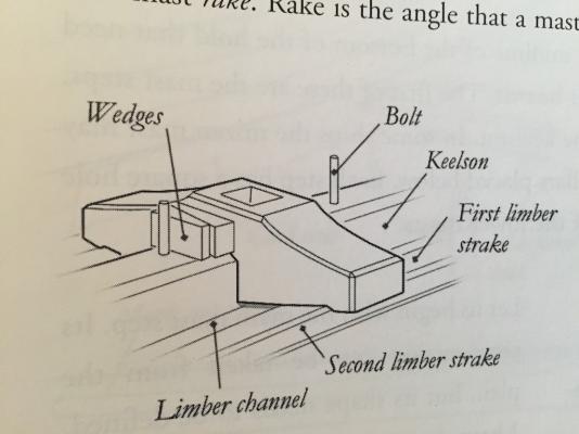

- 186 replies
-
- 16
-
-
Brig Eagle by robnbill - 1:48
robnbill replied to robnbill's topic in - Build logs for subjects built 1801 - 1850
Thanks to all for the likes and nice comments. I actually started researching and drawing this ship almost a year ago. She is a fun build. Very different from the Connie yet, her brief important career was inextricably tied to that of the Connie and her officers (or at least some of them). -
Brig Eagle by robnbill - 1:48
robnbill replied to robnbill's topic in - Build logs for subjects built 1801 - 1850
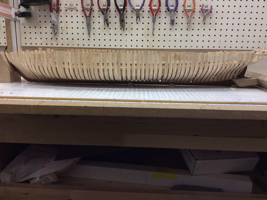
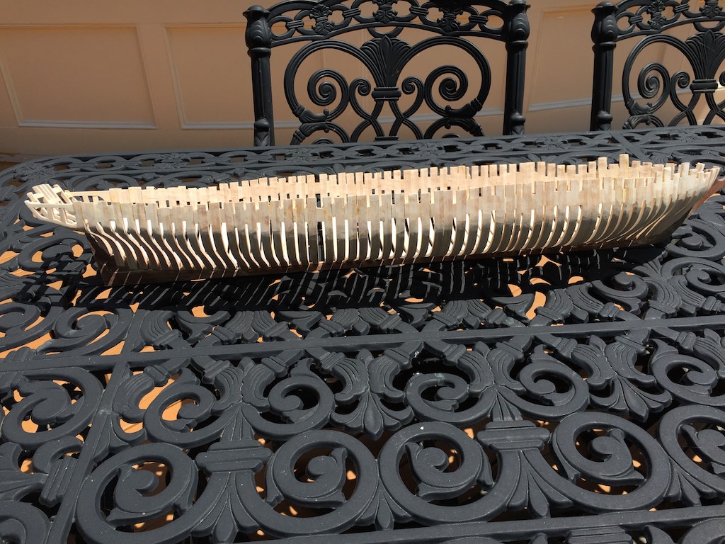
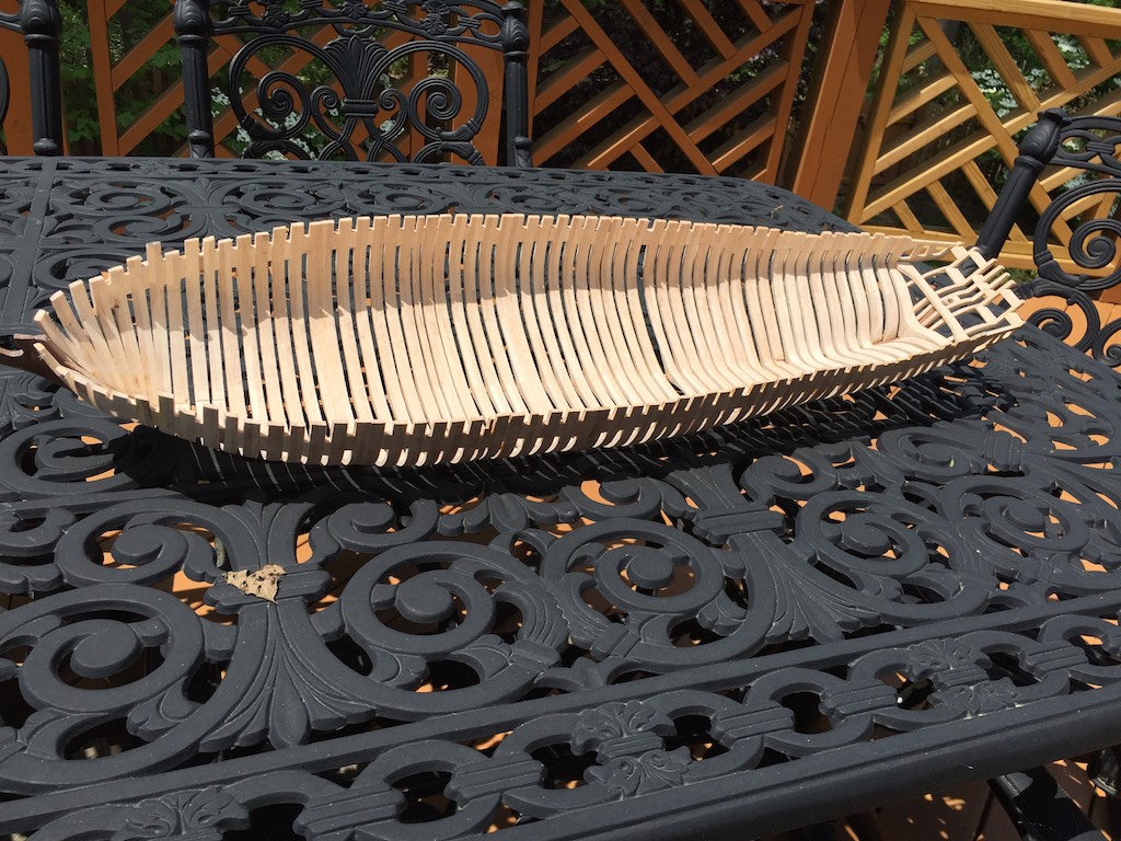
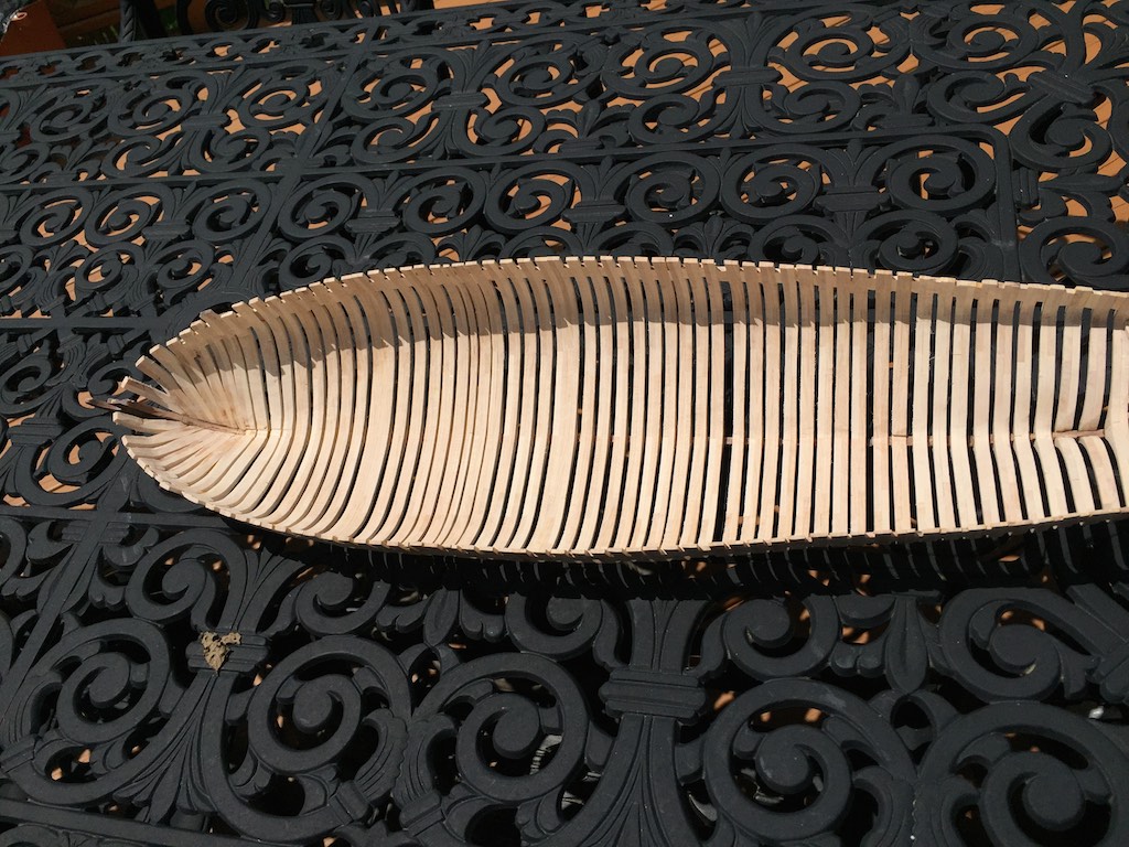
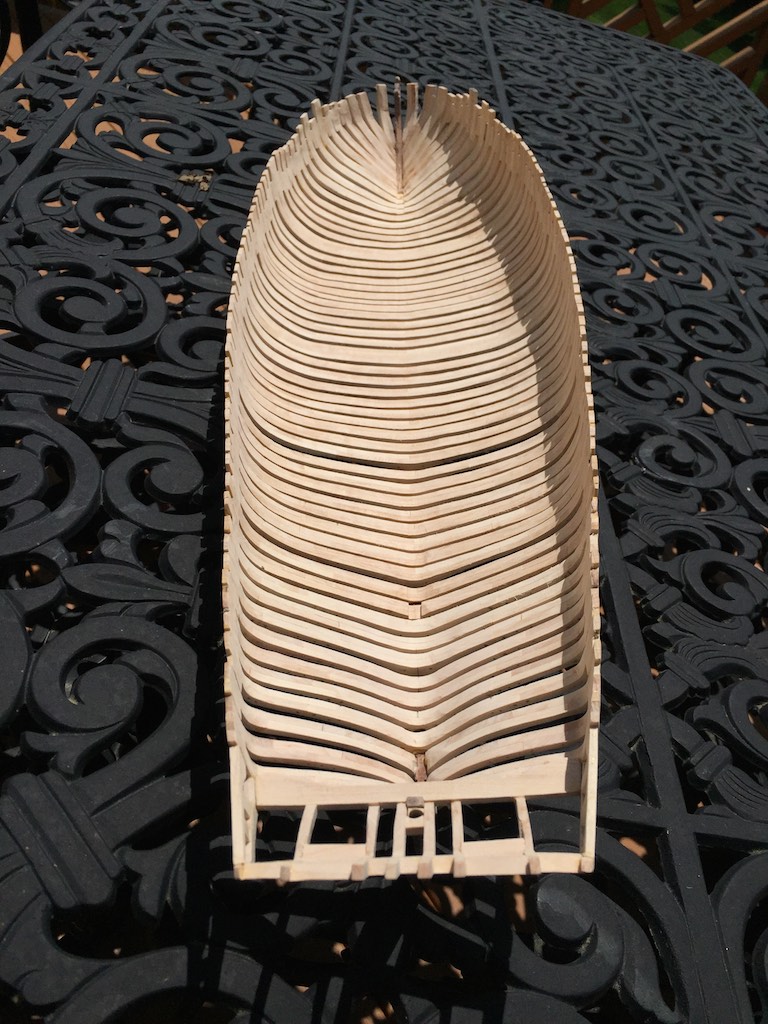
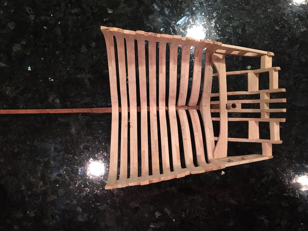
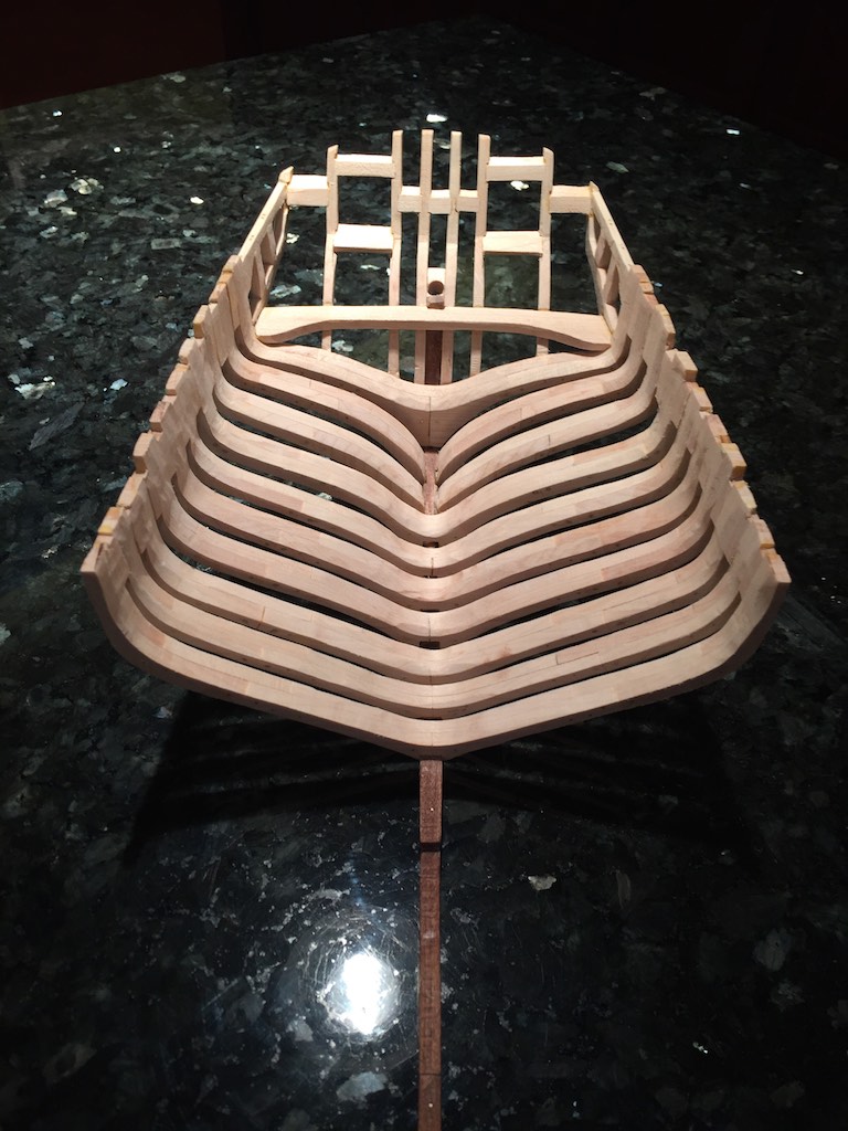
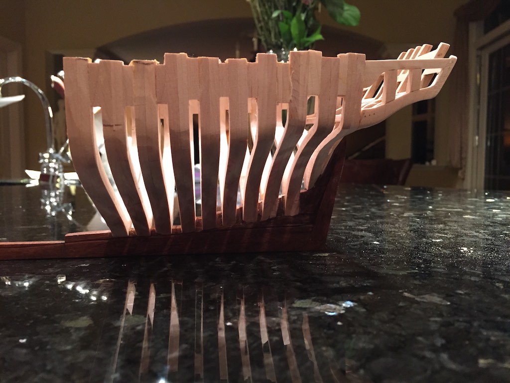
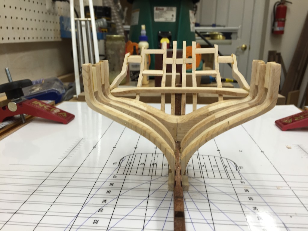
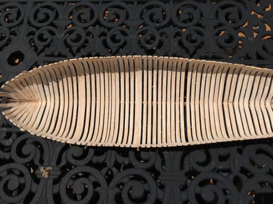
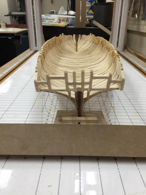
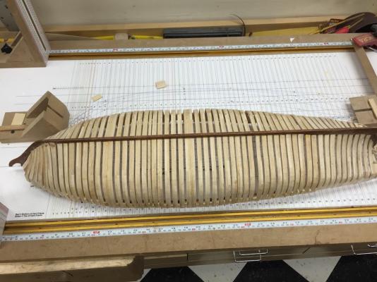
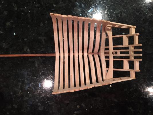
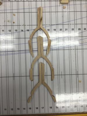
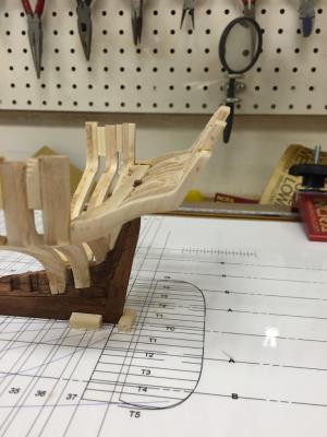
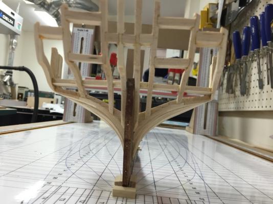
I was able to complete the installation of all the frames. Tomorrow, I will start the fairing both inside and outside. I also will be adding the clamp to the interior once the interior fairing is complete. The hull is interesting. This follows the "as-Built" documented by Dr Crisman in the keel assembly as well as the frames spacing. Also note the two pair of cant frames near the bow which extend higher than the others. While all the frames will be trimmed, these will still extend above the cap rail to form timber heads per Dr. Crisman's latest book. I will probably leave the spacers glued into the tops of the frame since that part of the ship will be planked and cover them. The cannon ports will be cut later. The Gantry jig should make this easy both in locating them and squaring the port sides to the keel. I have also framed the stern, how much of this will be exposed after framing is still undecided.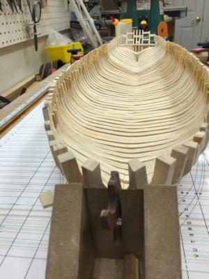

- 186 replies
-
- 18
-
-
Brig Eagle by robnbill - 1:48
robnbill replied to robnbill's topic in - Build logs for subjects built 1801 - 1850
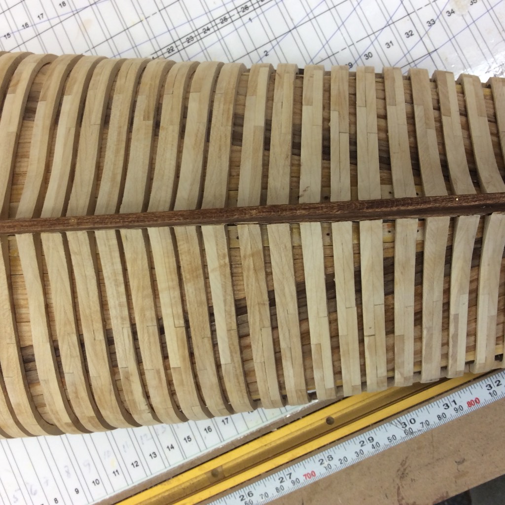
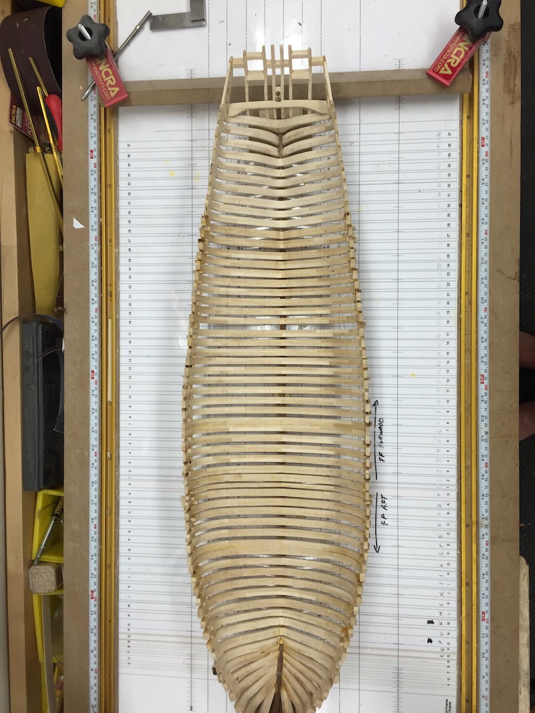
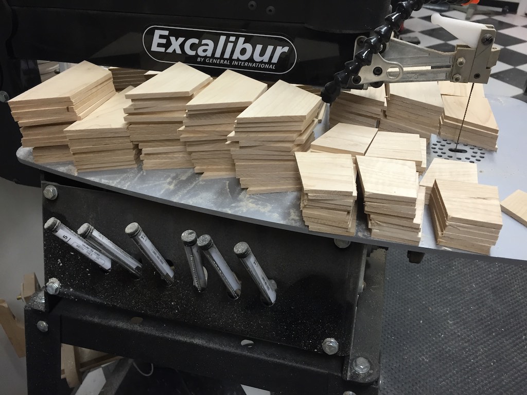
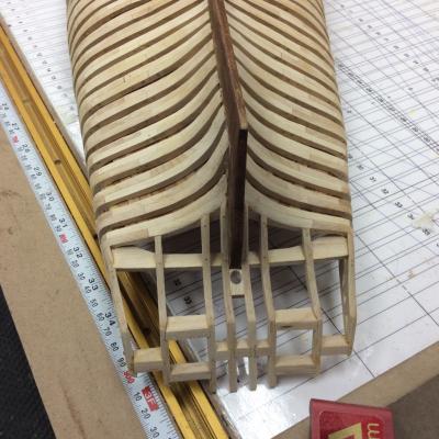
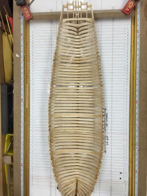
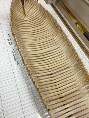
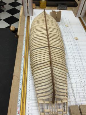
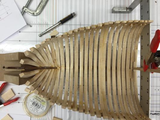
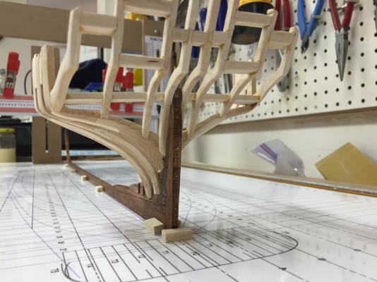
Once I got a bit beyond the bow section, I was able to start cutting standard form pieces to make the frame blanks. This sped things up dramatically. So after cutting a bunch of blank forms I started up the frame pipeline. I would use rare earth magnets to hold the pieces edge to edge while gluing. Once the glue set, I would glue up the side and clamp the two sides together. Once this comes out of the clamps, I cut the template for the frame out and glue it to the surface using thinned white glue. Once this is dry, I cut the frame out on the bandsaw leaving a small border all the way around. Then it is off to the oscillating sander to sand the frame square to the lines. If this does not have much of a bevel I leave it like this. If there is a large bevel, I will take some of this off with the sander. Then it is back to the bandsaw to cut out the notch for the keel. Then fitting everything to the ship. The gantry provides a great platform to insure the frame is glued square to the ship in all directions. It also provides a sturdy clamping surface. Since the horizontal member on my gantry is a heavy metal bar, I can also use it as a clamp itself to hold the frame tight to the next one. I have managed to get all the frames forward of Frame X installed and 2 aft of Frame X. I ran out of the precut frame pieces and had to stop and cut more. Luckily for me, when I ripped a bunch of strips out a few days ago, I guessed pretty close to what I was going to need to get all the remaining frames done. So I cut all of that up today so I can finish assembling and mounting the frames. I know I have said this before, but I will say it again, the gantry Jig makes it so easy to work on the ship. No guessing dimensions, many checks that can be done from plan lines to squaring everything. I am so glad I let Ray and Dave take me to the REALLY dark side. Anyway, once the frames I had installed were set, I carefully removed the ship from the jig. I was really curious to see it turned over. The photos of the ship below show a number of things, first, I have a lot of fairing to do on the bow. Once I started in with the square frames, I trusted the lofting lines and sanded square to each one. This should allow me the minimum of fairing. On the other side, It could also mean I have to remake a bunch of frames if I did it wrong, but I think the lofting lines are working. The other think you can see clearly in these photos, is of the spacing of the frames. I am following the as built so the spacing is different almost every frame. What you can't see clearly here is the first futtocks are all facing aft fro the bow to Frame X. After frame X, they are reversed. This also is following Dr. Crisman's work. The skinny third frame from the top is Frame X per Dr. Crisman. If you recall, I renumber all of my frames to follow the dissertation. Frame X was the only ½ thickness frame. The double frame shown is just aft of the forward mast. There will be a second double frame underneath the main hatch. After fairing the hull, I also plan on cutting the limber holes on each side of the keel. These were notches cut into the bottoms of the frames and are also documented by Dr. Crisman. After gluing up the last frame set I had in the pipeline, I spent the remainder of the day cutting new stock. I have enough cut now to make all the remaining frames.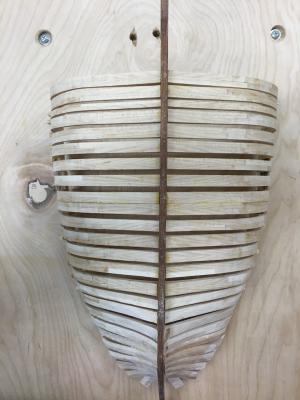

- 186 replies
-
- 13
-
-
Brig Eagle by robnbill - 1:48
robnbill replied to robnbill's topic in - Build logs for subjects built 1801 - 1850
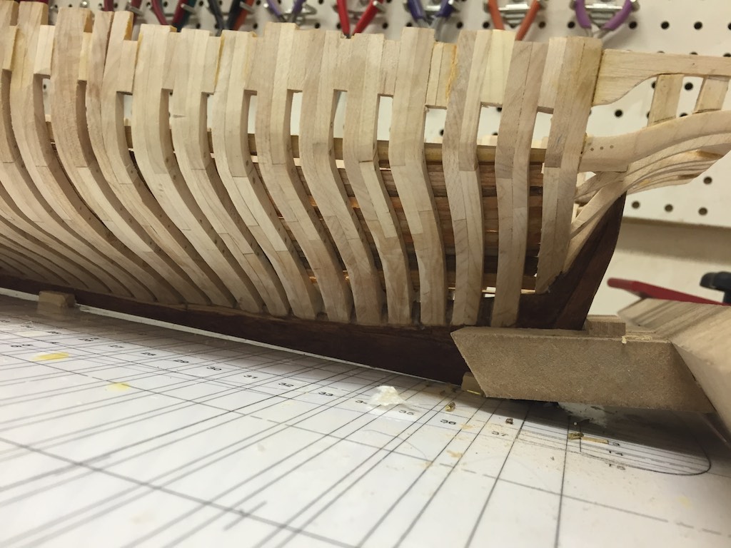
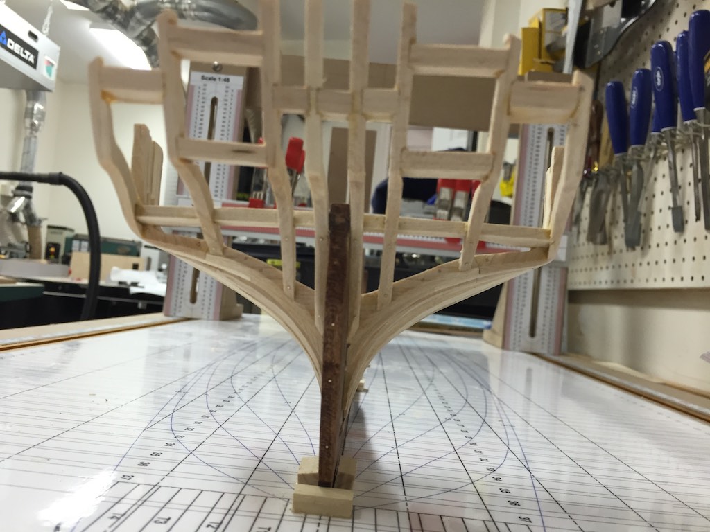
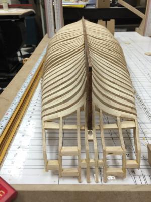
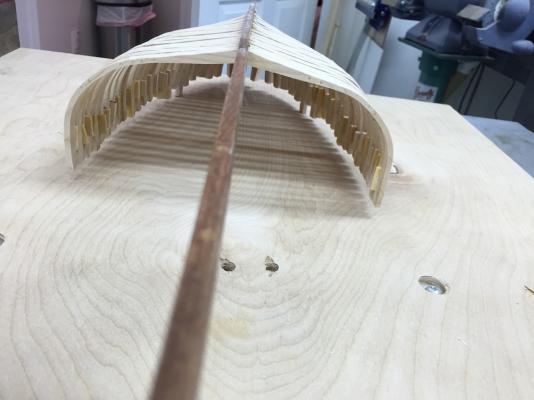
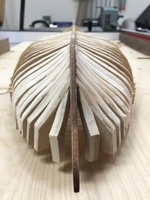
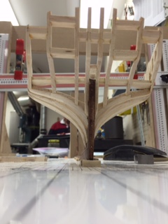
I was able to get the bow cant frames installed. Now I can work on the square frames. Yeah! I am happy to have all the half frames/Cant frames behind me. I still need to do a bunch of sanding cleanup on the inside and outside of the cant frames. I left more meat on the bones of these. I found it easier to sand them down than to recut them if I beveled them incorrectly when off the ship. Anyway, here are a couple of photos on the ship where it stands today. The darker frame is the test frame I built before starting the frames. It is standing where my frame X will be.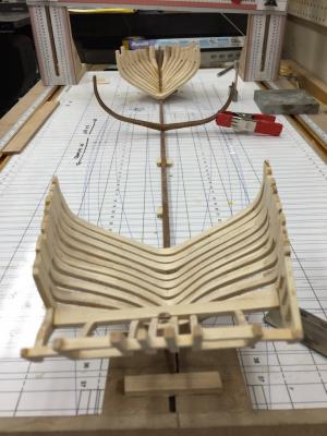

- 186 replies
-
- 14
-
-
Brig Eagle by robnbill - 1:48
robnbill replied to robnbill's topic in - Build logs for subjects built 1801 - 1850
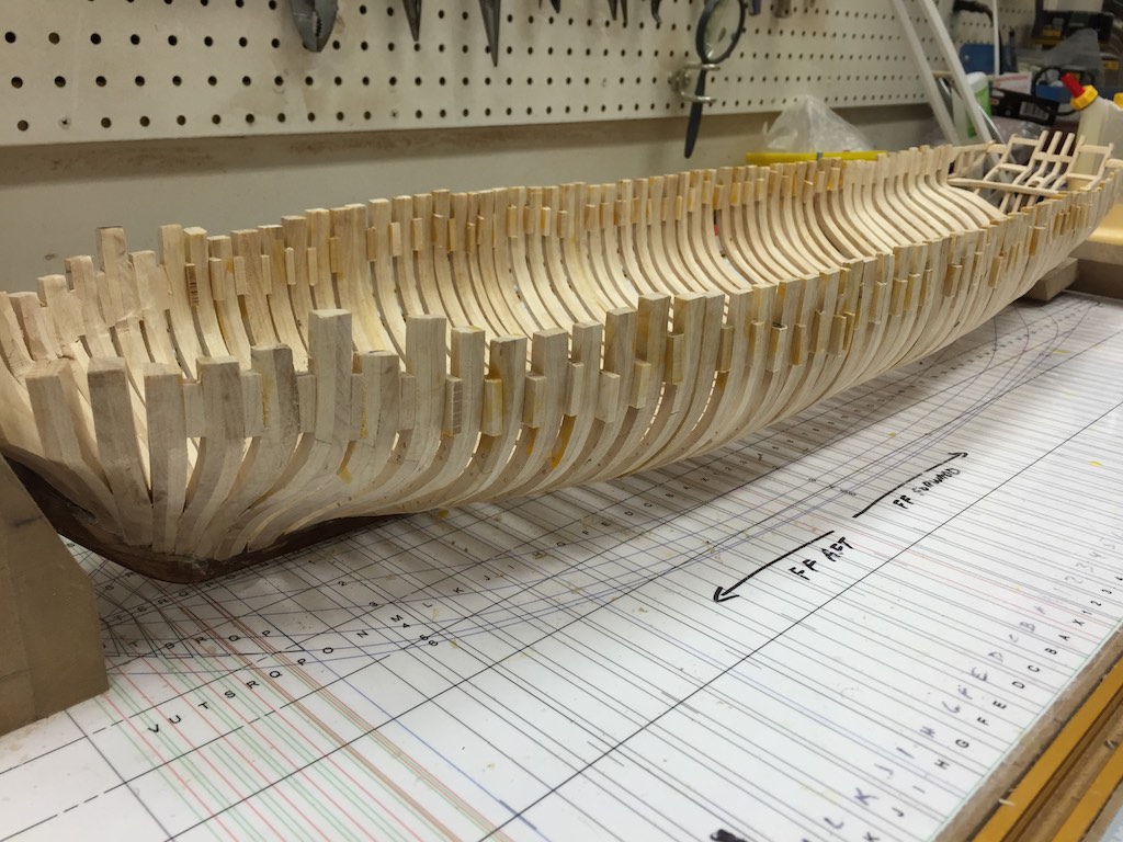
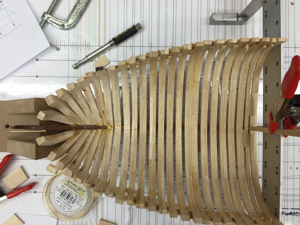
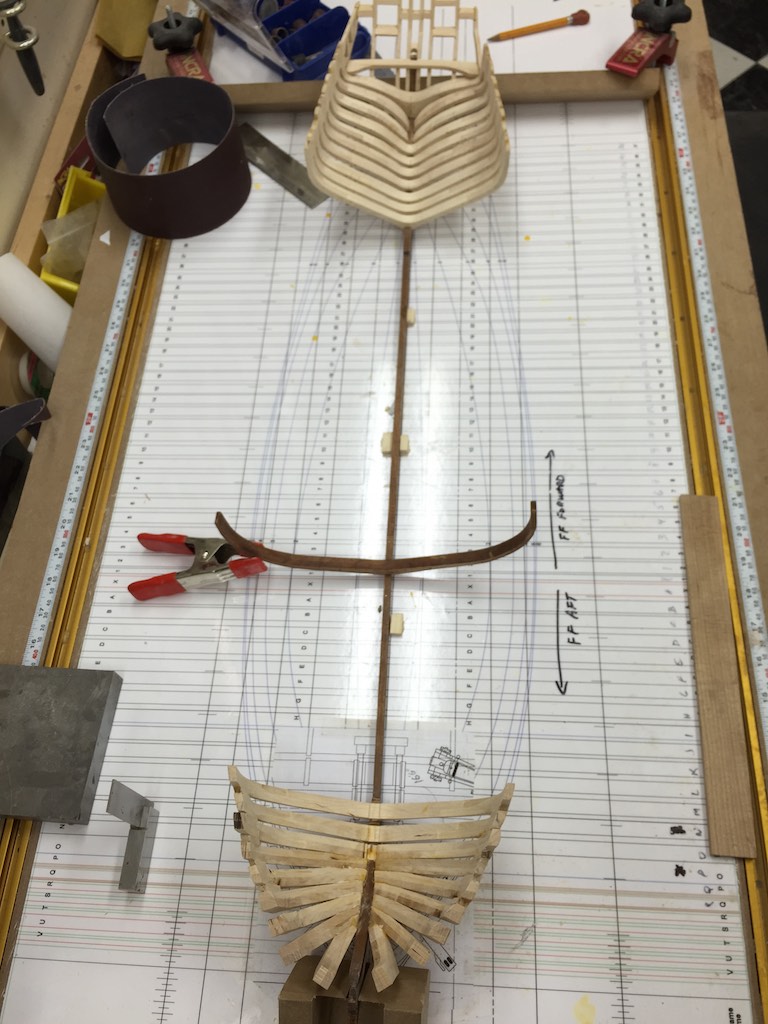
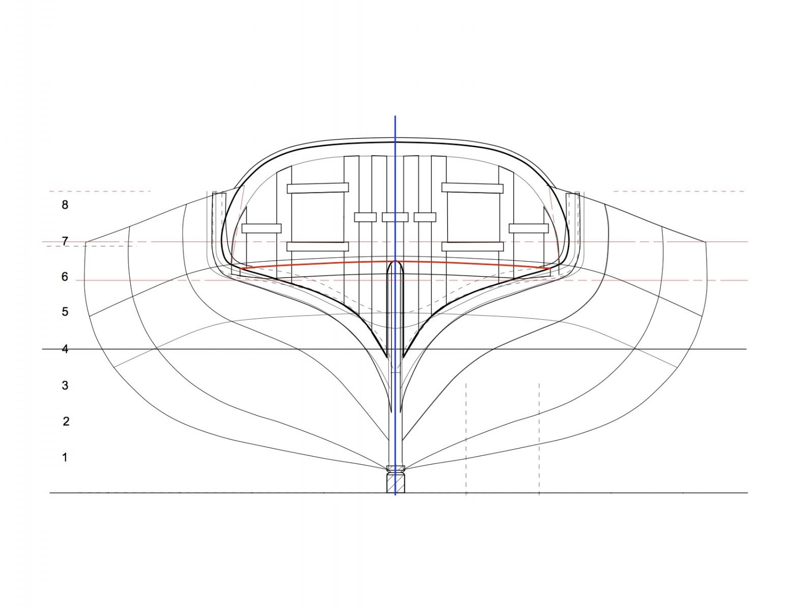
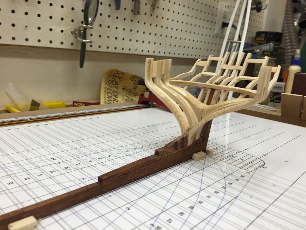
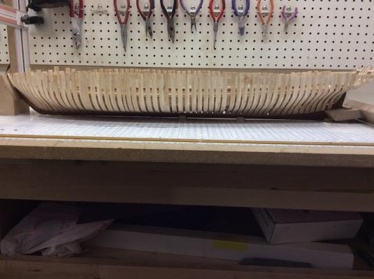
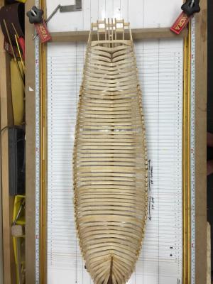
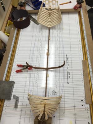
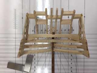
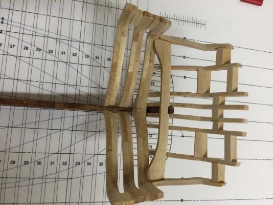
It is smaller. One of the unique parts of this build is I am trying to follow the frame spacing that Dr. Crisman found when documenting the wreck. While the frames were consistently the same size, at least at the 1:48 scale and with a few notible exceptions, they were not evenly spaced. The spacing they did have was well documented by Dr Crisman. The previous models built of the Eagle had the frames evenly spaced per the practicum by Gene Bodnar. Gene simplified the model and intentionally spaced the frames evenly because it looked better and was easier for the first scratch build. While that is true, it is also ignoring the documentation from the wreck. The ship was built quickly (in 19 days) and the wreck showed this. Many of the frames were built of green wood and some still had bark left on the sides. Prior to finalizing my plans I pulled all the frame information that I could from the various publications and calculated the widths at the 1:48 scale to see if I needed to change the sizing of the various frames. However the differences in them were too small to show at the 1:48 scale. However, the spacing between the frames was different enough that it could be shown. My master plan on the build board has the specific spacing shown by Dr. Crisman. The gantry jig allows me to space these according to the plan pretty easily. It might look sloppy in the end, I hope not. My goal is to hopefully show a very imperfect ship, built perfectly for the job at hand. Attached is a photo previously taken of the stern. You can see in the drawing below it the master which shows how the frames are sort of seemly randomly spaced.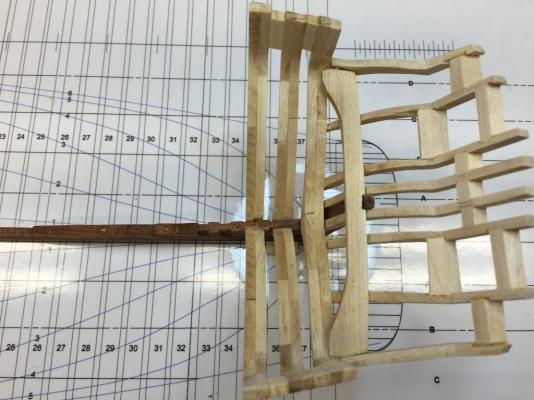
-
Brig Eagle by robnbill - 1:48
robnbill replied to robnbill's topic in - Build logs for subjects built 1801 - 1850
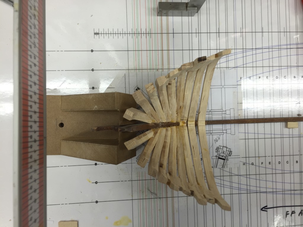
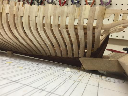
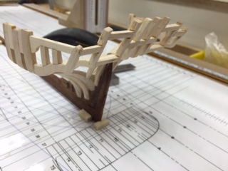
I have spent a lot of time working on the stern frames. Most of these frames should have been constructed as half frames. However, I found there was so little deadwood to attach them to they were very weak. After working constructing them and mounting them a number of different ways that left me very unsatisfied, I finally decided to build them as full frames then will modify them over the keel to appear to be the half frames since the frames would have been butted against each other over the keel/deadwood. Cutting a small groove should provide this. I have done some preliminary fairing, more sternward. I am fairly happy with the way the stern has turned out and now will work on the cant frames in the bow. You can now start to see the frame spacing being unevenly spaced. Anyway, here are some photos of how she currently sits. Much work still to be done! Since this is my first attempt at scratch, please feel free to jump in with any advice. This is very much a learning project.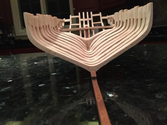


- 186 replies
-
- 11
-
-
Brig Eagle by robnbill - 1:48
robnbill replied to robnbill's topic in - Build logs for subjects built 1801 - 1850
I was able to also get the side rails on the stern. Of course the handrails will go over these, but these finish the framing in the stern. In addition, I added the block for the rudder post to go through as it passes through the stern.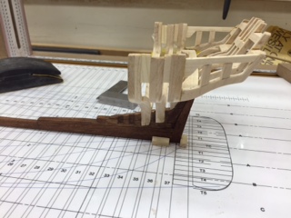
-
Brig Eagle by robnbill - 1:48
robnbill replied to robnbill's topic in - Build logs for subjects built 1801 - 1850
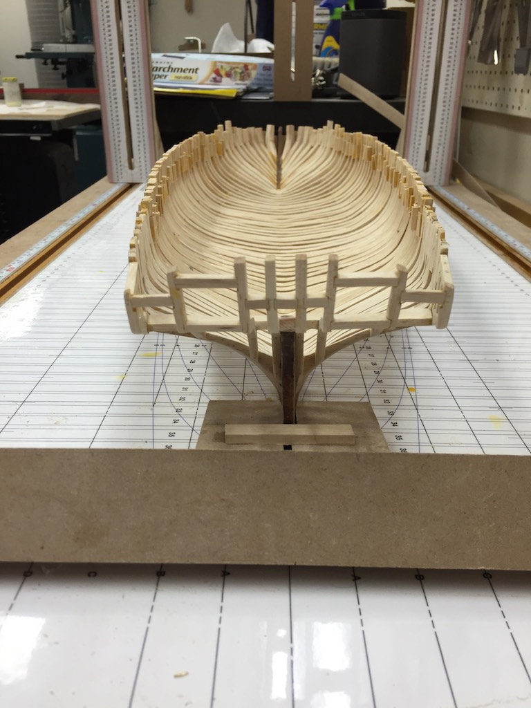
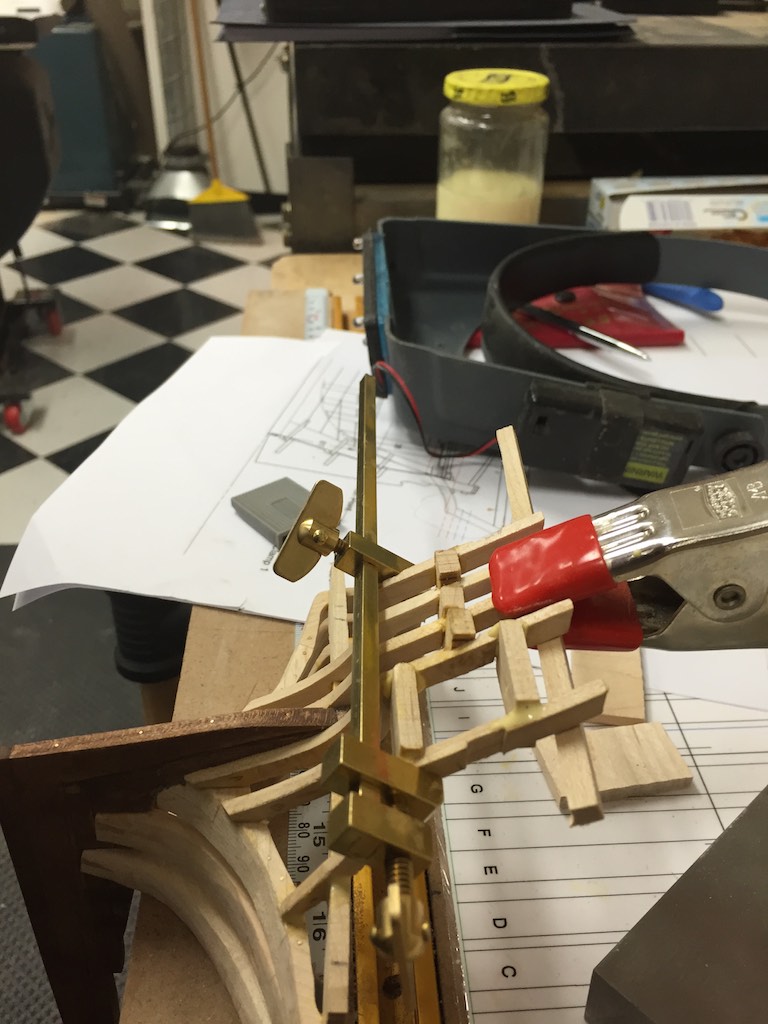
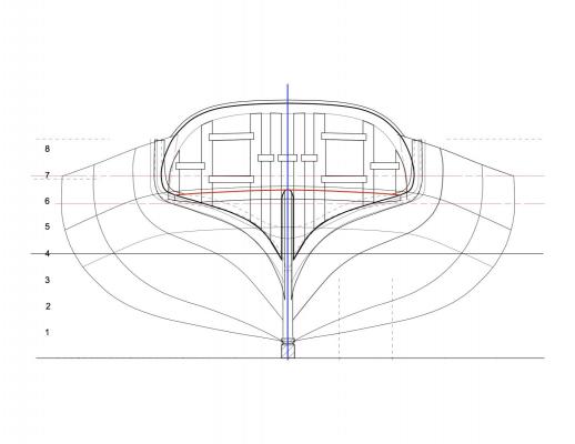
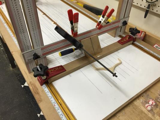
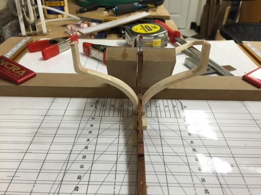
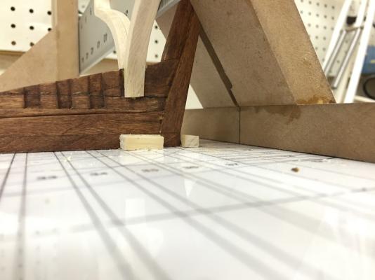
I have been focused on the stern framing this week. Rather than box it in solidly I wanted to frame it like it might have been done. Since none of this actually survived on the wreck, this framing is conjecture. We know there were no cant frames in the stern so everything aft of the fashion frame are counter timbers. There are two gun ports out the stern which need framing. I first worked up a method for framing which was straight forward. Given the speed which this ship was built, they did not go for complexity when simplicity would do. The first task was to design the sternmost deck beam. This beam is notched into both the fashion frame and the outermost counter timbers. I cut this with the camber the deck would have and used the top of this as the guide for mounting it to the ship. The inboard profile provided the height this beam should have on the centerline. Once this was established it was a simple process to use the gantry frame to align the beam and clamp it in place for glue up. I started lofting the counter timbers using the inboard profile. Then once I had that I cut two counter timbers to mount either side of the sternpost deadwood. These provided the planes needed to cut the other timbers. Since the stern of the ship is flat I had to maintain the angle of the counter timbers above the main deck beam. Below the beam the angle would change allowing the timber to meet the fashion frame. I notched each of these for the beam. This provided the two points the timbers were attached to the hull. They were also attached to each other with carlings which stiffened them and framed in the gun ports. I planned on having four sets of counter timbers. I waited to cut the last set until the other sets were installed on the stern since the outer timbers were rather complex angles and would require extensive shaping to the hull. Below are the first three sets of counter timbers. Notice the upper arms of each are the same. The angles change at the notch allowing them to hit the frame. I found the easiest method for installing the timbers was to use a spring clip to attach a flat beam across the upper stern. This gave me a third point for the timber to be clipped to when installing. The brass bar clamps recommended by Wayne have come in very handy here! The carlings were all glued in then sanded down to the ship's stern planes once the glue was dry. Lastly, I trimmed the ends of the deck beam and prepared the outer counter timbers. These were notched to fit over the end of the deck beam. I left these to dry over night. In preparation for trimming the counter timbers, I printed out the stern elevation. I also made note of the height of the center below the handrail. With the stern elevation and the height of the timber tops on centerline it was a snap to set the gantry at the appropriate height and mark the tops of the two center timbers. Then I carefully placed a cut out of the stern elevation across the timbers using the centerline and the top line as the guides. By placing the top of the cutout on my previous marks, then aligning the bottom with the center of the keel, I traced the outline on the other timbers. Then it was a matter of cutting and sanding the stern to the profile. Once this was done, I did some final cleanup of the glue squeeze outs, then drilled the holes for the pinning and glued the brass into them with heavy CA. I trimmed these off and sanded smooth. I did one final faring of the stern with the frames then wiped the entire assembly with mineral oil to remove all dust. I touched up the keel assembly with stain where needed. Now I will move forward with the remaining half frames. Here are photos of the stern as it sits in the gantry.


- 186 replies
-
- 14
-
-
Brig Eagle by robnbill - 1:48
robnbill replied to robnbill's topic in - Build logs for subjects built 1801 - 1850
Thanks all for following. Kees, your trawlers are nothing short of amazing. I can only strive for your attention to detail! After today I am a solid advocate of the gantry! I built and installed the first frame to be attached to the keel, Frame 35H. These are two half frames immediately forward of the fashion timber. Since the fashion timber has no slot and minimal slot for the keel and , attaching the two half frames allows me to align everything then attach the fashion timber. However the gantry also showed that I was too aggressive in lopping off the tops of my fashion timber. So it is too short. So I will remake it tomorrow. Hopefully as I move along I will stop building by the adage that "the third times the charm". I am also finding that shaping the frames is getting easier to judge as I go along so this just give me a bit of extra practice. The gantry allows me to very accurately align and square the frames as well as check the level and spacing between the outside edges of the half frames. Using this I was able to see where I needed to adjust the bevels so it fit the dimensions between the outside upper ends of the frames. I plan on adding spacers between the frames at the top so they will be firmly held.

-
Brig Eagle by robnbill - 1:48
robnbill replied to robnbill's topic in - Build logs for subjects built 1801 - 1850
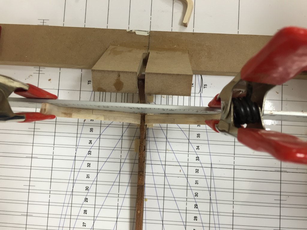
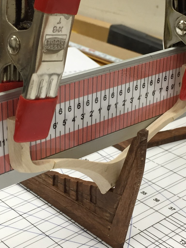
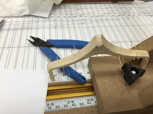
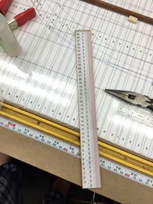
I shaped my first frame actually being installed in the ship today. I started with Frame 36 which is the aft most frame. Since it sits so high on the stern, and it is the fashion timber I decided to make it a full frame. This also aligns with the notches found on the ship since there were no notches for this frame in the deadwood. After gluing up the boards and gluing the frame template to the face, I used the bandsaw to cut near the lines. Then I used the Oscillating sander with varying diameters of sandpaper rolls to sand to the lines with the frame square to the table. This gave me the hard line I needed on the bottom forward and the top aft of the frame. Then it was a matter of sanding the bevel between the two. After test fitting it to the keel I used the drill press to drill the pinning holes through it. I found putting a backing block at an angle in the vise below the drill allowed me to keep the drill square to the face of the frame. I could sight down the edge of the frame and make sure it was parallel to the drill. Then I glued the brass wire into the holes. Tomorrow I will sand the flush. I also printed a scale on an 8 ½ sheet of paper. This was a subset of the scale I used in the gantry. I glued this to a strip of cherry. This provides a quick check on the ship without having to convert from inches or MMs. On a side note I found out that when working with Maple, it is important to have bandaids around if I am using an Xacto blade since I invariably end up pricking my fingers somewhere. Blood makes a mark on white maple!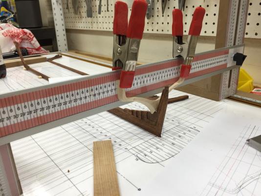

-
Brig Eagle by robnbill - 1:48
robnbill replied to robnbill's topic in - Build logs for subjects built 1801 - 1850
I will be happy to share my drawings for free if you want them. There are two flavors. The original drawings I did which follow the Bodnar practicum closely, except for areas that were changed after Dr. Crisman's comments. I do have lofted frames in DeltaCAD that you could have. I also have the latest generation of drawings that I am using for my build. I call this the "as-Built" set since the frames are based on what Dr. Crisman found rather than a more stylized version that is from the practicum. DeltaCAD is pretty inexpensive and is easy to use. I have all of the plans in PDF, except for the frames. Since I printed them at home, I did not need to make exportable files. When you get ready, let me know. -
Video of a serving machine being used
robnbill replied to achuck49's topic in Masting, rigging and sails
As Tony said, they are pretty easy to build. I built mine with gears and tubing from a local RC shop. The only thing I would do differently is gear it so one turn of the handle would produce more turns in the served line. I have it currently set so it is one to one. This makes me do a LOT of turning if fully serving a shroud. Bill