robnbill
-
Posts
841 -
Joined
-
Last visited
Content Type
Profiles
Forums
Gallery
Events
Everything posted by robnbill
-
 When I did my Connie, I was really unsure of the rigging. I knew and had confidence in woodworking. However, I found that rigging was actually fun to do. The lines started making sense and it really made the ship start to seem more alive. However as each line went on, it made me more leery of approaching it since I could see myself accidentally catching something while working on something else. It is just so easy to do when you have your magnifying hood on and focused. However other than that, I really enjoyed rigging. I cannot express the relief once she was safely in her case. My current ship, the Brig Eagle will be rigged. The next one will in all likelihood be an admiralty build of the Naiad and will not. You are doing a great job on your Connie. I am enjoying following your blog.
 -
What's the fun in that! I broke the nose on my Connie twice. The first time badly but I used epoxy to glue the splintered spar back together. The second time finished off the first time. I ended up breaking out the Acetone and removing it and turning a new spar. Much happier with the results.
-
Hang in there. As you already know from your past projects (but sometimes it is easy to forget) is that wood is very forgiving. Worst case scenario, is you cut something off and remake it. Not the optimum solution but one that we al have done one time or another.
-
Julie, you might also try to take a thin saw and remove balsa next to the frames on the other side. It would not take much. The the bow has a place to move. Otherwise you are putting it under compression and as Keith said, wood doesn't bend in two directions well.
-
Julie, once you think your ready, you can take black pinstripe tape and run along a line of the hull (or use a thin strip of wood). this will show you any dips in the hull.
-
Imperial or metric for lathes and mills?
robnbill replied to tkay11's topic in Modeling tools and Workshop Equipment
My current model is a 1:48 of the Brig Eagle. For me, I find it easier and more accurate to work in Metric. That said most of my dimensions are in both, but when it comes to cutting wood, I go to metric. -
Hi Julie, You are doing a great job and I am watching your progress with interest. I wanted to let you know that once the planks are glued on they are very strong. Even a single layer of planks, when glued to the bulkheads and edge to edge to each other are strong. When you have a double layer it creates a very resilient shell. Since you also have a balsa inner core, this hull will be very solid once all the layers are glued in place. As far as handling, once you have your boat fully rigged, even without sails, it will be very easy to snag the rigging on things - hands, clothes, kids fingers. On my Connie, I actually snagged the jibboom and snapped it off while wearing magnifying lenses and focused on another area of the ship. The rigging and spars are what are delicate in the final model. So if you are like me, once the ship is rigged you will not want anyone touching it. I well executed model REALLY makes people want to touch it - especially kids. That is the reason so may are safely ensconced in cases.
-
Tool for Sanding Inside of Curved Pieces
robnbill replied to ChrisLBren's topic in Modeling tools and Workshop Equipment
I found the Grizzly spindle sander to be a pretty good one. It is small enough to go on the bench top but light enough to move it off when I don't need it. Less than $200 on Amazon. http://www.amazon.com/Grizzly-G0739-Oscillating-Spindle-Sander/dp/B00DQJPCFU/ref=sr_1_fkmr0_1?ie=UTF8&qid=1449023210&sr=8-1-fkmr0&keywords=grizzly+model+g0739 -
Very nice and your stand is ingenious and I think is well suited for the yachts period. If I remember your first log entry said this was destined for your daughters window. I think it will look great in the window. However, if there is no UV protection on the glass I am afraid the sun will do a number on your wood and colors.
-
Tool for Sanding Inside of Curved Pieces
robnbill replied to ChrisLBren's topic in Modeling tools and Workshop Equipment
Besides hand sanding, rifflers, and files, I also use a number of power tools. I have a disk sander that I use to sane the outside of curves/frames. I use a spindle sander to sand the inside curves/frames. Once the frames are on the ship I use a Dremel with the EZ Lock arbor and the EZ Lock sanding disks. These come in various grades from the course to pretty fine. I would caution that these can burn if run at too high of speed so need to be run at reduced speeds. Once something in on the ship, or I need to do some quick fine sanding, the Dremel is my tool of choice. However all three power tools are well used in my shop as I work through building frames. -
Hi Lucky Star, I used a mixture of beeswax and turpentine to coat all the thread I put on the ship. All the thread was also hardened. All of my standing rigging also had to be dyed black. I chose to use India Ink. My process was to take a length of the rope, run it through the ink and my fingers to make sure it soaked in well. Then I hung to dry over night. The next day I ran the beeswax mixture over it and ran it through a paper towel. This removed all excess of the was mixture and any dye that was not soaked in the rope. At this point it was ready to rig to the ship. I did it right after the wax was put on it. This helped stiffen the rope after it was in place. If you search this forum you will also find out about hardening the ropes. This is done by hanging the rope with a weight over several hours to allow the fibers to stretch and set in. This can be overdone and damage the rope if the weight is too heavy. The idea is just to give it a gentle stretch. Some rope (such as that supplied by Syren) is already hardened and lightly waxed so it is ready to go straight out of the package. A couple of points I would raise. There are differing opinions about the use of beeswax. You can find a number of threads on this subject. Next, there are those that attach their masts to the ship (re glued) and those that use the rigging to hold the masts in place. I fall into the latter group. My feeling is a mast foot that is glued deep in the hull will be a problem if it ever has to be repaired. What I did was to leave the standing rigging cinched as I installed it, but not terminated until the ship and all standing rigging had a chance to settle in. As I ran additional rigging I might find an area that needed to be tightened up or loosened a bit. This allowed me to do the final mast alignments once all the standing rigging was on the ship and stable. Once this was done, I terminated and dressed the ends. This process took a number of weeks so the rigging was able to settle in before termination. This is the process that worked for me. That doesn't mean it will for you. Try different modelers methods until you find what works for you.
-
Craft supply, modeling supply stores, Amazon all sell the pin drills. You can get a set of incremental sizes fairly reasonably. Of course, just like any other tool you get what you pay for. I found a cheap set with many of each size for wood. They tend to break. I also spent a lot more to get high quality pin drills for brass. Those I only use on metal. Also be aware that the brass pins that come in a kit are used primarily to hold the wood strips while they are gluing. Then they are removed. Treenails are added to the strips once the glue has dried. These can be made out of wood such as bamboo, brass or copper, and once installed are clipped and sanded flush with the planks. However depending on the scale of your model treenails can be too large, even small ones for the model. Another method for marking treenails is to make faux nails by imprinting the wood with a very sharp pencil. This can be used pretty effectively if the scale is too small for wood or metal. There are many examples of models with treenails of all kinds as well as those who have used the brass. It is a look and it is your model so play with the various methods and choose one you like.
-
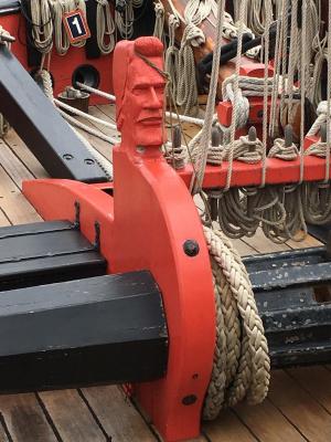
Just in case, here is a photo I took of that carving on the replica a couple of weeks ago.
-
Brig Eagle by robnbill - 1:48
robnbill replied to robnbill's topic in - Build logs for subjects built 1801 - 1850
Well the shipyard was shut for a fall vacation. Now the Brig is underway again. I am now starting the focus on the main deck and stairs to the berth deck. Today I created the gratings. I used the process that Gary used along with the TFFM to make these. I used Maple to make the grates. First cutting the notches and strips using a carbide blade in the Byrnes Table Saw. I also cut notches into a block of MDF to use as a build guide. Once all the notches were cut I changed the blade to a slitting blade with much finer teeth to cut the notched strips out. Then it was just a matter of installing the notched strips into the build guide and tapping in the strips. Once a grate was assembled, I brushed on a thinned white glue and carefully removed it from the guide. After a final tapping of the strips down into the notches I left them to dry. Once dried I used the disc sander, and rotary tool to shape them down to fit. The grates shown have had one coat of stain. They are a bit blotchy but this will be corrected once the first stain is dry. Next I will focus on the remaining ladders down to the berth deck.- 186 replies
-
- 14
-

-
Hi, Sorry to not get back to you sooner. I am actually on a ship south of Tahiti and headed for Auckland at the moment. I have not found the beeswax and turpentine mixture to keep glue from holding the knots. The thread is still porous so there is still teeth for the glue to hold. I do use CA to lock knots. I use a needle to apply a very small amount to it. Perhaps it will fail after 20 years or so.
-
I know there has been debate on beeswax back and forth but I ended up using a combination of beeswax and turpentine on my rigging. It soaked into the rigging well and left a matrix of wax throughout the thread structure once the turpentine evaporated. This left the thread slightly stiff but pliable. This also worked on soft materials such as the cloth I rolled for the hammocks. Bill
-
I think it depends on where you got your rope. Some rope, that Chuck's (Syren Ship Model Co) do not require stretching. Other rope does need it. If you are unsure, you can test a section of it. The main thing is you want the rope to be set so it does not stretch when rigged.
-
Brig Eagle by robnbill - 1:48
robnbill replied to robnbill's topic in - Build logs for subjects built 1801 - 1850
A short update on the Eagle. She now has her exterior planking completed and spiked. Next I will turn back to the interior and give my new Byrnes saw some exercise with the ladders and gratings.- 186 replies
-
- 16
-
-
Brig Eagle by robnbill - 1:48
robnbill replied to robnbill's topic in - Build logs for subjects built 1801 - 1850
It has been a productive couple of weeks since my last update. I completed the cannon/carronade prototype. There are still some minor revisions I will make to the final versions but I met my goals in 1) Building each end to end 2) finalizing my build processes, 3) and having prototypes to inform the main deck planking. I ended up also turning the carronade castors out of brass as well. They work really well in pivoting around the pin. Once these were done I set them aside and returned to the ship. I finished planking above the wales and added the cap rail. One item that Chrisman added to the ship in his last book were a pair of timber heads on each side of the bow. These are shaped from the tops of frames N and P and required slots to be cut in the rail to allow them to pass through. I used Dave's excellent method of cutting the first scarf joint and laying electrical tape in cutting all the scarf joints. This made it very easy to join the rails. The bad news is the joints are tight and you really have to look for them to find them in the walnut. Next I will continue to plank the outside below the wale. Once this is done, I will return to the main deck to plank that. These first two shots are of the ship ready to have the cap rail attached. This shows the Hammock battens installed on the main deck beams. I am not sure if I had included this in the other updates. Here is a close up of one of the cap rail scarf joints. This is a shot of the stern with the cap rails installed. Of course once the rails were installed I had to see what the cannon looked like. Note - I did not build a quoin for the prototype carronade. Hence it always pointing to the sky. The final carronades will have quoins installed. I also plan on lowering the carronade a bit in the final version. Here are several shots of the two prototypes. I put temporary spacers underneath them.- 186 replies
-
- 16
-
-
Ken, You are doing a bang up job on the ship. On the treenails, at 1:64 the treenails will be very small. I would figure roughly a 1" hole would be about 1/64" or .016 rounding. That would be the equivalent of about a 26 gauge wire. Since you are not painting this, you might think about using brass 26 gauge wire. Drill a small hole touch the wire to some thick CA and insert it in the hole. Later trim and sand. This is much easier than trying to tree nail with something that small and the brass will look smart against the wood color but not too bright to take away from the details you are adding. Just a thought.
- 481 replies
-
- 1
-
-
- rattlesnake
- model shipways
- (and 1 more)
-
Brig Eagle by robnbill - 1:48
robnbill replied to robnbill's topic in - Build logs for subjects built 1801 - 1850
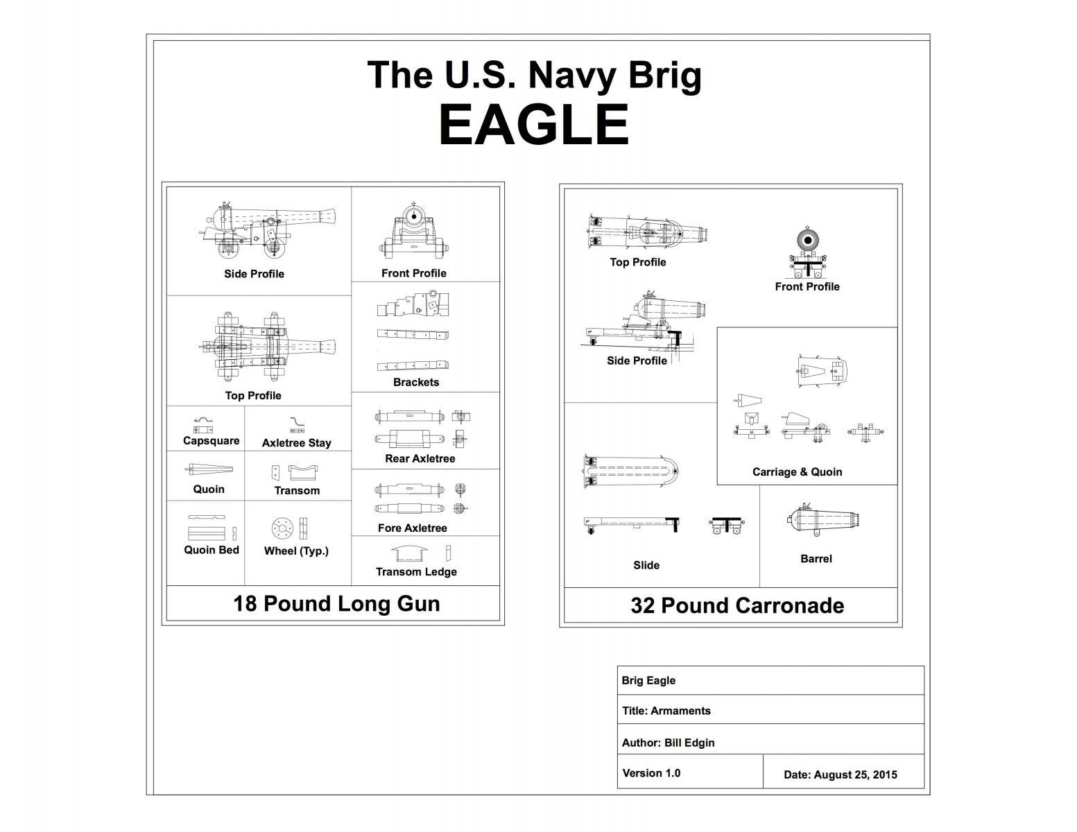
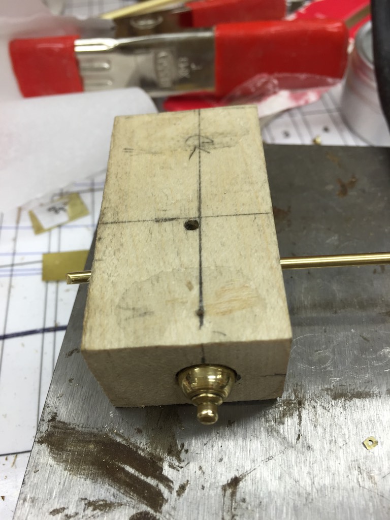
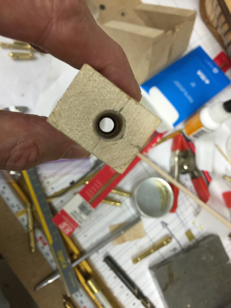
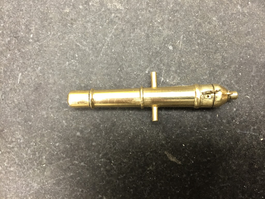
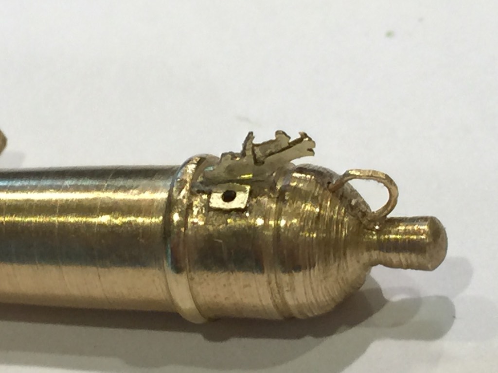
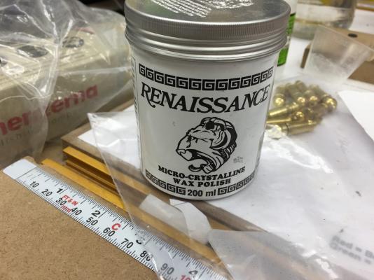
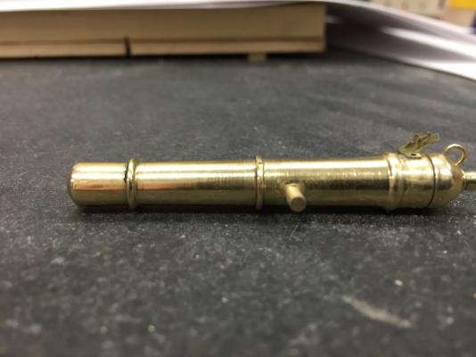
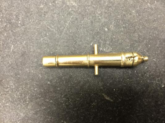
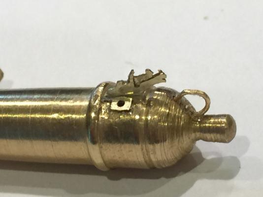
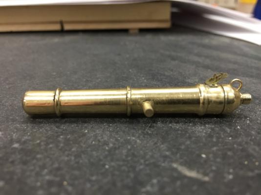
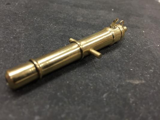
I have been actively working on the cannon assemblies since the last post. My goal is to solidify my plans on the cannons/carronades. Once I have assembled at least one of each, I will use them to solidify my deck planking strategy. There are a number of areas that I focused on. First, the carriages. I used the TFFM instructions for building long gun carriages with a healthy dose of input from Crisman's book as well as that in the Connie AOS. I also scoured the internet for examples of carronades over the period to come up with a design that might have been used on the brig. I am happy with the results. With the carriage design out of the way I turned to the gunlocks. These were definitely part of the Brig's armament - as it was on all of the British and American ships at the time. They were mounted to each cannon in preparation for a battle then removed and stored afterwards. Since this Brig was built and fought in only one battle when she was 30 days old, I really wanted to show them mounted to the cannon. I drew designs up in CAD based upon what is known of the locks at the time. Enoch Hidden had the contract for them. However, while there are contractual records, there are no known plans for his locks at the time. However there is at least one of his locks circa 1820's that does show his design is pretty much a copy of the British locks at the time. So I used photos of the British locks to design these. I wanted to create a design that would have a 3D effect. This was a challenge given the small size of the locks. After trying my hand at cutting and filing I decided IF I was going to do this, I would either have to buy a set (not an option for my scratch build) or try my hand at creating my own Photo Etch. So after reviewing the work done by others on this, I chose the Micro-Mark Pro Etch to try my luck. As the instructions (and others have made clear) the artwork is critical for this. I went through a number of iterations on this before I settled on my artwork designs. Then once I had the first set etched, I did two more in varying thicknesses to play with the layering to achieve the effect I was looking for. My design had 4 pieces. The plate over the touchhole, two sides and a center. I found that making the center out of thicker metal gave me the look I was going for. Here is a photo of my first attempt. This is close to final but has the same thickness plates for all three. This is a test barrel so the ends are rougher than the finished barrels. Once the gun locks were ready I started working on a jig for the barrels. I tok a block of maple and drilled a hole through it the size of the cannon barrel end. Then I enlarged the hole to fit the larger end of the barrel. This allowed me to insert the cannons into the jig and tap them in place and it held them firmly. Then I drilled a hole through the jig in the place I wanted to insert the trunnions. Once the trunnion holes were drilled I took a short piece of the trunnion rod, inserted it through the guide holes and held the cannon through the jig. This kept the barrel rigid and indicated the perpendicular point for the touch hole as well as held it for me to center punch the points to drill for the cascabel ring holes. Here are photos of the jig with and without a barrel in place. Also I decided to leave the brass bright. I know it will tarnish over time but am using Renaissance Wax to polish it. This has been shown to hold the tarnish at bay for as long as lacquers. At least it will be easier to remove if need be in the future. Here are some photos of the first completed long gun barrel. It has the final gun lock configuration. The change is subtle but sufficient.


- 186 replies
-
- 17
-
-
I ordered the Micro-Mark Pro-Etching kit and set to work trying to make the gun locks. I will not go into the processes to make them, I will over that in the log. I ended up with a lock that is about 1.5" thick which is about right given the ones I have seen on the web. I used multiple layers of brass to give a more 3d appearance with the thicker plate in the center. I also made a jig to align the trunnion holes moving them below centerline. I also have put together the plans for the carriages so my next step will be to complete a carronade barrel then construct at least one with carriages of each. This will allow me to assess the amount of decking I want to install and confirm whether or not I want to only have guns on one side. Thanks you all for you input into this process. I know I have a better cannon for it. The first shot below shows a test on the prototype gunlocks. It had the same thickness plates for all the pieces. The remaining shots are of the first real long gun barrel that will be installed on the ship. It has the gunlock configuration as described above. I left the trunnions long until I finish the carriage and confirm the lengths. Then I will shorten.


-
Brig Eagle by robnbill - 1:48
robnbill replied to robnbill's topic in - Build logs for subjects built 1801 - 1850
Thanks. The file worked fantastic. The only negative thing was it was too wide to use between the rings on the cannon barrel. That was my fault for not ordering a small enough file. I have learned a great deal about files in this process. If you want to know more about file terminology there is a great pdf at Nicholson Tool Guide to Files. Brass is so soft that it tends to clog the teeth of a file. I ordered a wire file brush that kept the grooves clean. So I would file awhile them clean the grooves with the brush. This made the work much easier and with a cleaner surface on the worked metal. -
Brig Eagle by robnbill - 1:48
robnbill replied to robnbill's topic in - Build logs for subjects built 1801 - 1850
Just a quick update. I have completed turning the barrels for all the guns (one side). My plan is to leave the other side open to expose the deck below. If this changes I can always turn more barrels. A few quick take aways from the experience. First, I changed from turning ⅜" stock to ½" stock. The former was large enough for the cannons but it was too small to fit tightly in the NovaChuck on the lathe. Just like turning wood, even after careful centering, I still needed to true up the blank in the lathe. Once in the headstock, I used the spindle support to hold the end to mill the end and find the center. Once a divot was cut into the center, I drilled the barrel. This was done with an electric drill and the lathe turning. This kept it true to center. I found a combination of tools that worked best. The carbide finishing tool worked well with truing. The diamond shape cut the brass like butter. Once I was near where I needed to be, I would use files, and a HSS parting tool to smooth the brass. The HSS tool left a nice finish on the barrel. Finding the sweet spot took time. I found pushing too hard resulted in chattering, too soft and it created small pins or chips coming off the tool. The angle was also very critical. However, when you were in it, you would get the nice spiral shavings. Writing down the target measurements on a sheet of paper taped to the wall in front of me really sped up the process. Still needed to stop and use the calipers as I went along, but I only had to measure the piece in the lathe, not the model barrel. Once the barrel was completed, I would cut the forward end first. Once parted, I would true the end then return the live center back to the barrel end. Then I would sand first with a 3m very fine sand pad, followed by 0000 steel wool. The cascabel would then be cut off. I used a hack saw holding it where the cut needed to be and let the lathe do the work. Once off the lathe, I would use a rotary tool to clean up the cascabel. The power buffers would start with jewelers rouge, fine, then progress through very fine and finally very very fine. I will follow up with a more detailed description and photos.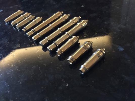
- 186 replies
-
- 11
-