robnbill
-
Posts
841 -
Joined
-
Last visited
Content Type
Profiles
Forums
Gallery
Events
Everything posted by robnbill
-
 Geoff, You are doing a fantastic job on all the rigging details. Don't think for a second I am not going to lean on this heavily once I start making the rigging for my Eagle.
 -
Wow, I am just catching up on your build log. I have a question on your feet you made in post 391. When you were using the slitting blade in the mill how did you manage to keep those small pieces from flying across your shop once they were cut off? I just am learning how to use my mill. Your work is amazing.
-
It is looking better. I know it is tempting to show the nails boldly. However, if you look at the holes in the photos, the diameter is probably ¼". While the nail heads would be larger, if you round up to ½" diameter that would still only be about 0.2mm or 0.006" at your scale so subtlety would be the desired effect. Seeing enough to know they are there without them shouting at you.
-
The thin rip jigs work extremely well with the 10" Sawstop I use. I found a similar jig made by Infinity Tools https://www.infinitytools.com/thin-rip-tablesaw-jig that is slightly cheaper and looks to be a bit more substantial than the Rockler tool. This is the one I have been using. Trying to cut strips between the fence and the blade is very dangerous and error prone.
-
Theoretically I like the idea of rigging everything off ship. However, I find my mind just doesn't work like that. I end up rigging everything on ship. For me that is what works. Everyone has a different method. Fore to aft, aft to fore, bottom to top, etc. You just have to see what works. You will find your groove as you rig.
-
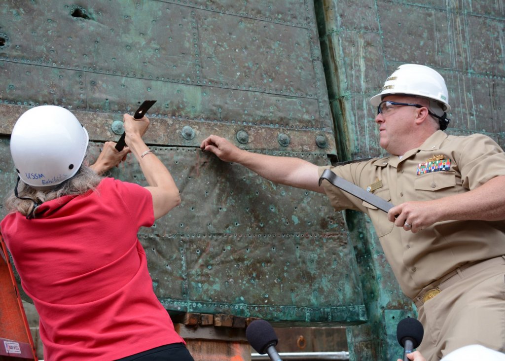
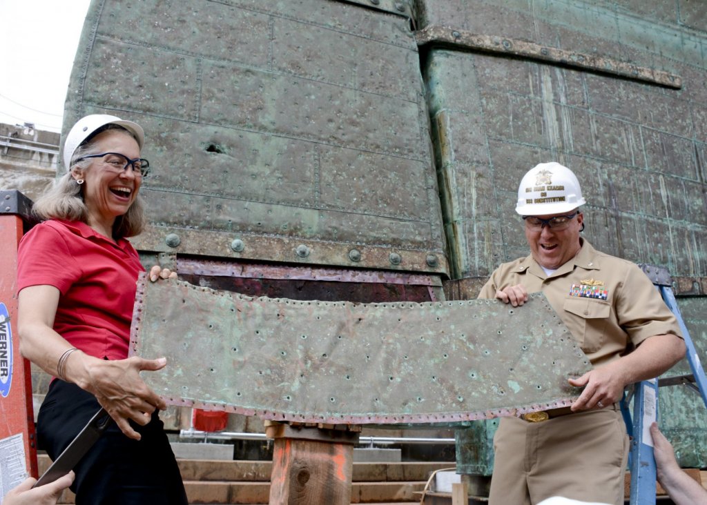
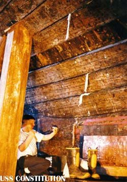
Here is a photo from the Connie when they were removing the copper plates from the rudder. You can see the various dimples created by the nails in the copper plate. The older photo is of a previous restoration when they had removed the copper plate. You can see the nail holes. You can also see the frames where the board in the upper frame was removed.
-
Brig Eagle by robnbill - 1:48
robnbill replied to robnbill's topic in - Build logs for subjects built 1801 - 1850
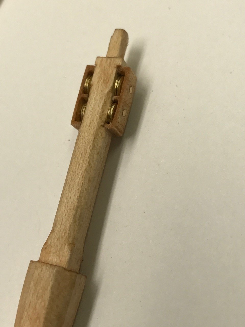
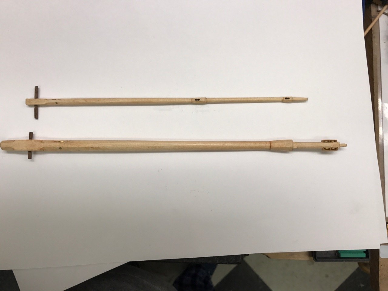
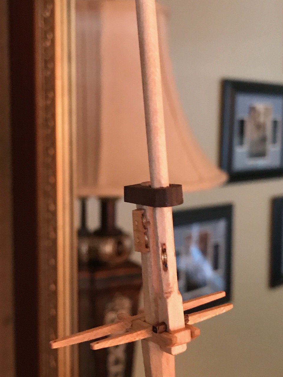
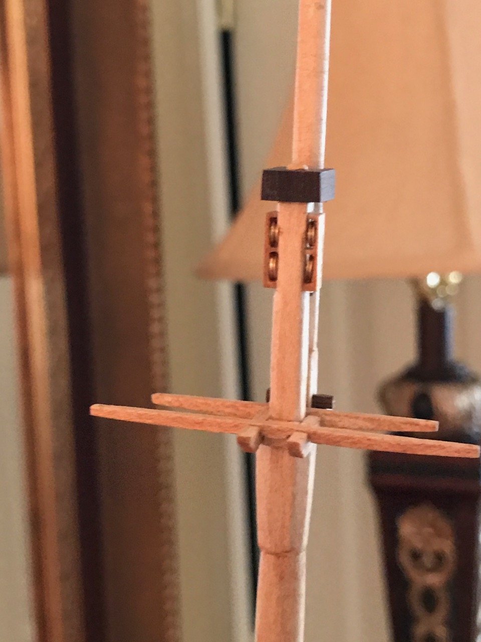
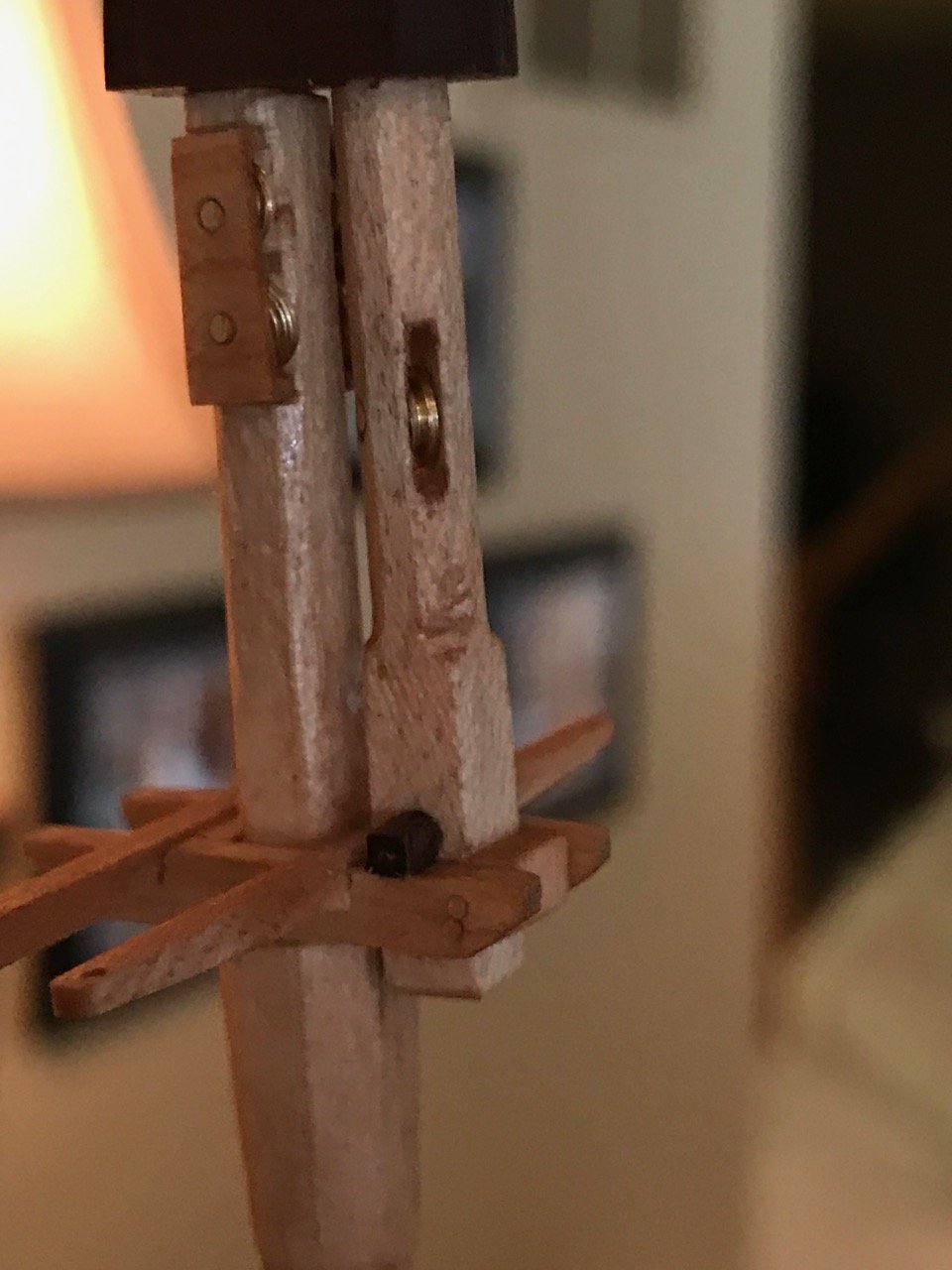
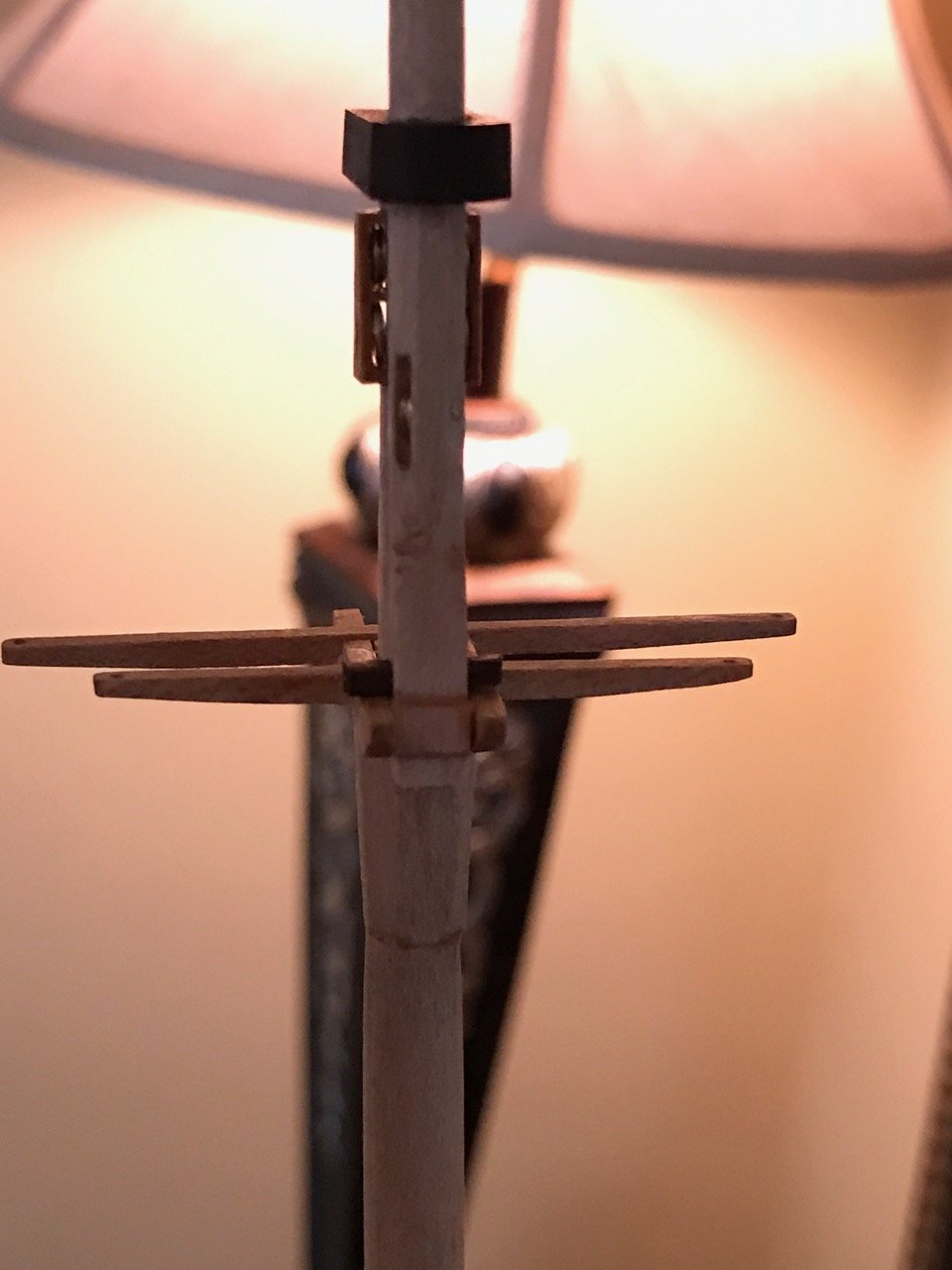
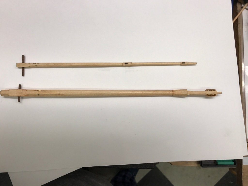
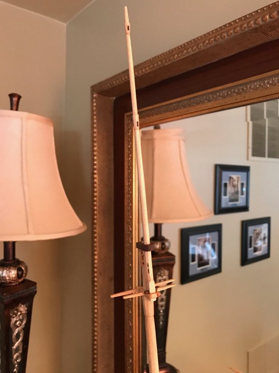
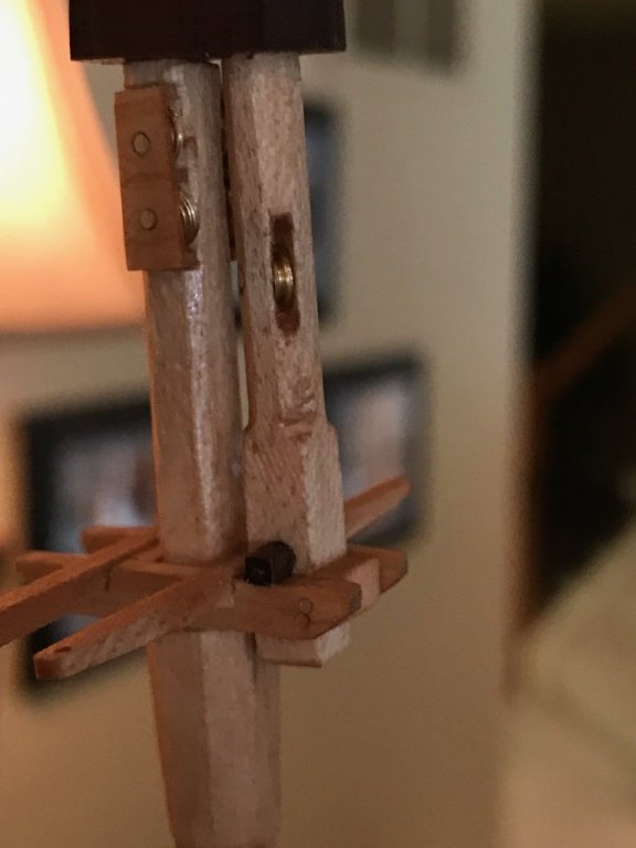
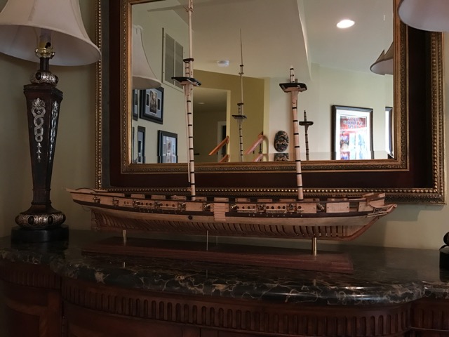
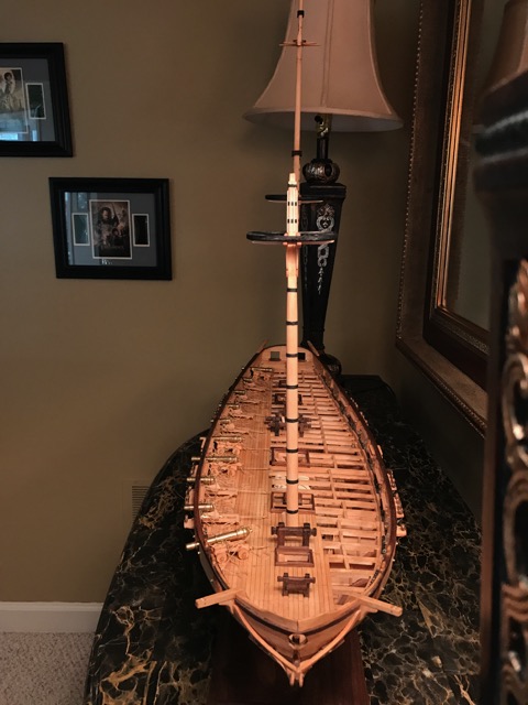
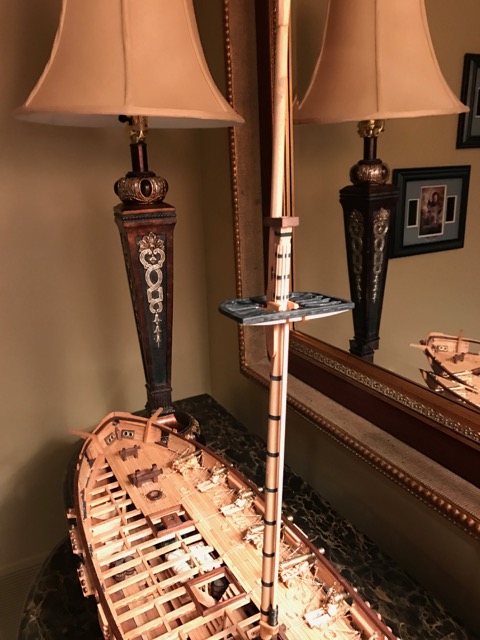
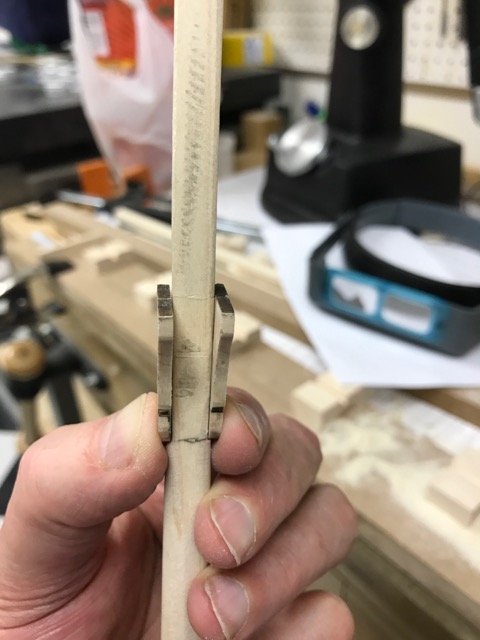
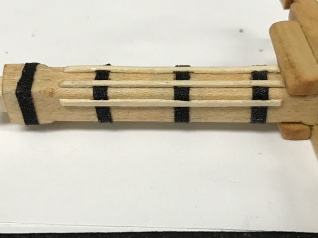
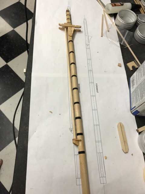
Just an update on progress on the Eagle. I have been putting quite a bit of time into researching the rigging configuration for the model. Dr. Crisman has a fuzzy hand drawing of how he thinks the ship's Rigging Profile would have looked. For my purposes, I need to drill down to much further details. My model will not have sails but there will be a combination of standing and running rigging on the model. I am using several references. The American ships were rigged following most, if not all the basic rules used for British Ship's of War. This makes things much cleaner. Given the expediency with which the Eagle was built (19 days) there were in all likelihood shortcuts in some of this. There certainly was with the hull construction. However, following these guidelines along with Crisman's expert opinions should give a good approximation of the ship as she sailed to battle. Here is a list of the reference material I am using in this effort.= Crisman's The Eagle Steel's Elements of Mastmaking, Sailmaking and Rigging Lee's Masting and Rigging of English Ship's of War Lennarth Petersson's Rigging Period Ship Models David Antscherl's Swan Vol 4, Rigging a Sixth Rate Sloop (while much earlier than the Eagle, it is a valuable treatise on actually rigging a model The first order of business was to attempt to identify those lines shown in Crisman's drawing and record these on a new CAD drawing (I am attempting to do) of the rigged ship. I also had an email discussion with Ed Tosti asking his advice on approaching designing a detailed rigging profile. His sage advice was to develop a detailed spreadsheet that would capture all the lines as well as the details around them, i.e., size of rope, serving, color, blocks etc. I found that the Petersson book was great in identifying lines typical to that period. I used this in conjunction with the Crisman drawing to develop a list of those lines I would be installing. This could then be cross referenced with the Steel and Lee volumes to flesh out the details. One key aspect of this is deciding the size of the ship itself. Steel has a table for sizing ship's based on the number of guns on board. I will be using the 20 to 22 gun tables. There is a difference in line and block sizing between Steel and Lee. Steel's number tend to be slightly larger in both line circumference and blocks. However, there is also inconsistency in these tables that Lee's smooths out using common block sizing ratios. However, this does not answer which method to use. There was nothing left of the rigging in the wreck other than the lower chainplates and mast steps. However there was an inventory list for the supplies sold from Whitehall during the sell off of the Lake Champlain fleet and supplies in 1825. While circumstantial at best, it does point to those supplies that were common in the fleet. The sizes of running rigging and blocks falls more neatly into the Steel tables than Lee's So I feel comfortable using these. I have compiled my list of lines, but have only started working on fleshing out the spreadsheet. This will be an on-going project I will be doing in conjunction with completing the masting and spars for the ship. I had built a manual serving machine when rigging the Connie (1:92). However at 1:48 the Eagle will show much more detail in the rigging and require much more serving to be done than I wanted to do on my old manual machine. In preparation for this, I purchased Alexey Dumanoff's powered serving machine. It seems like a great machine and I can't wait to put it into service. It will be a great match for the Byrnes ropewalk. I also have been putting in time actually making sawdust (and brass shavings). The photos below show the ship where she stands. I have been playing with my Grizzly Milling machine trying to develop the skills to actually use it well. More on that later. For this update, I used it to build the upper mast cheeks as well as sheave slots for the masts. The sheaves were turned on the lathe out of brass stock. I decided I did not like the previous iteration of the topgallant masts that I had done. On the Eagle, Crisman call for these to be exactly the same. So I redid these building them in parallel. These like all my masting were done first by cutting square strips of Maple to the size of the widest part of the mast, then using files, chisels and sand paper shaping the various sections per the drawings. By doing the fore and main topgallants at the same time I was able to better insure they were matched section by section. I still need to build the foremast cross trees and caps. The main mast caps also still require fitting and I may decide to redo some of those before all is said and done. Anyway, that is where she is today. Once the foremast is complete, I will work my way through the bowsprit and jibboom, then the spars. At that point, I hope to have all the rigging spreadsheet filled out. This will give me a good estimate for the numbers and sizes of the blocks to be made as well as the inventory of rope I need to make prior to starting the rigging. Here is a close up of the topgallant cheek blocks. Topmast and topgallant masts. The fids will be cut to length after the cross tree is installed.Main mast topmast and topgallant masts. Main mast topmast and topgallant mast Main mast topmast and topgallant at cross tree.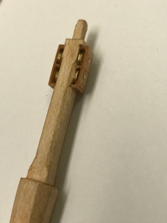


- 186 replies
-
- 20
-

-
Just realize that no matter what set you choose, you will still have tunnel vision. It is just optics. You. Ight see ligght from your peripheral, but it will not be in focus.
-
Reading/decoding Mamoli Rigging Charts
robnbill replied to robnbill's topic in Masting, rigging and sails
You are welcome. I am glad it helps. It took me awhile before I figured it out and then it became clear. They really did a great job on explaining where each line went. -
Brig Eagle by robnbill - 1:48
robnbill replied to robnbill's topic in - Build logs for subjects built 1801 - 1850
She was built for an inland lake and the shipyard was up a river that had a very shallow bar at it's entrance. She was unable to take on her ballast (which was magnetite ore) until she crossed the bar into the lake. There was nothing found of her rigging except the chainplates. Dr. Crisman felt she would have a tall rig, like that of the Niagara. She probably could not sail very close to the wind but that was not uncommon in those days either. Since it was an inland lake, she had no need of a deep hold for supplies. Water was readily available since they were sailing in it, food was available since they were never far from shore, so all they needed was enough room for the men and ammunition. Originally Dr Crisman put a ship's wheel on her, but after sailing on the Niagara felt it probably only had a tiller, so he revised this. Thanks for following the build. -
Brig Eagle by robnbill - 1:48
robnbill replied to robnbill's topic in - Build logs for subjects built 1801 - 1850
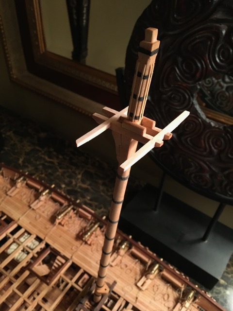
Here is the Eagle as she sits in the dock today. The upper mast sections for the foremast are still to be done. On the spanker mast I decided to go with 12 rings. This was based on the Model Expo Niagara. It was slightly less than what I had calculated but given the boom and the angle of the gaff was well within the tolerances. Since the Niagara was what Dr. Crisman used as his basis for rigging, this is the rig I turn to when questions arise in my build. Once the foremast is complete, I will start on the bowsprit assembly. The masts are currently just lightly wedged in place so ignore any misalignment. The final angles will be set with the shrouds. The mast sections are also not glued together. I plan on rigging the masts in place. Of course, as always, my plans are subject to change!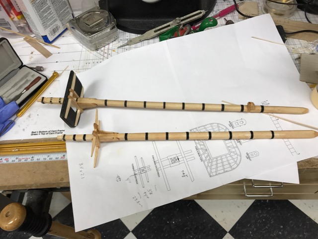
- 186 replies
-
- 19
-
-
All good advice. A note on the tablesaw. I have both a Byrnes and a Sawstop table saws. Since I am scratch building, I do buy rough lumber usually in 8" x 2" x 8'. So I use the Sawstop to mill the lumber down to smaller sections then use the Byrnes to perform final cuts on the smaller stock. On another note. 10" Table saws are VERY dangerous beasts. Every day, people loose fingers to these. The SawStop saw not only is a fantastic saw, it prevents this from happening. If you are in the market for a 10" TS. Look at the SawStop. Woodcraft stores as well as other sell them. I don't have any stock in them but I love the saw and highly recommend it for the 10". It will never replace the Byrnes for the close work, but it is a safer saw than the Byrnes. I need both saws. However as Chris pointed out, the 10" TS puts out a huge amount of dust. So dust collection both active and ambient is critical if you want the dust controlled.
-
Hi Samuel, Did I miss something? Which ship is your cross section of?
-
I have had the Veritas micro chisels for over a month now and wanted to update my previous email. I love using these chisels. I am working on masting for my Eagle and find these are the go to tool when making small cuts and bevels on the masts. They also work well in getting into tight corners to remove squeeze out. I also have to mention that the stereozoom microscope I purchased off eBay is also coming in very handy. While it is a large tool, it is sort of tertiary to this discussion since it allows one to see really small areas. A good example of how both of these tools came handy is when I was making the top mast platform. After I cleaned up all the squeeze out using my flip down magnifiers, I decided to see how mush left over I could see with the microscope. It was a huge amount. However, with the small chisels I was able to clean out all of this squeeze out cleanly. You ask if it made any difference since it was so small to begin with? I think so. Cumulatively, this type of squeeze out removes some of the sharp corners that while they might not be evident, once they were all done, did make the stop seem much crisper. Anyway, that is my story and I am sticking to it.
-
Brig Eagle by robnbill - 1:48
robnbill replied to robnbill's topic in - Build logs for subjects built 1801 - 1850
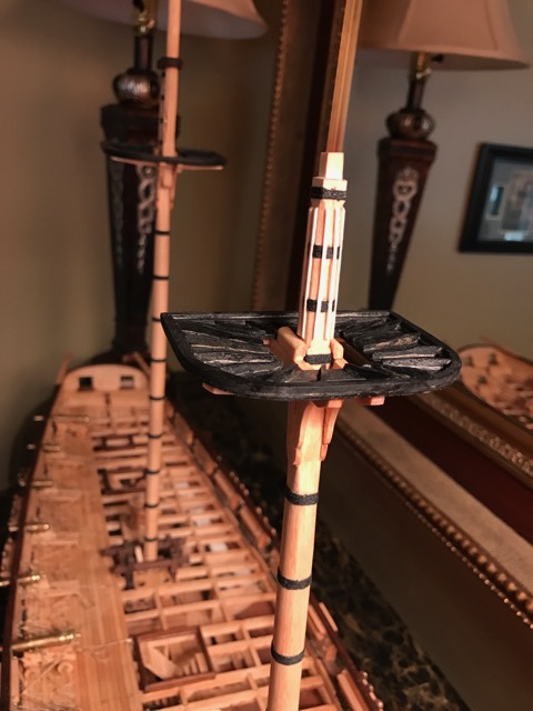
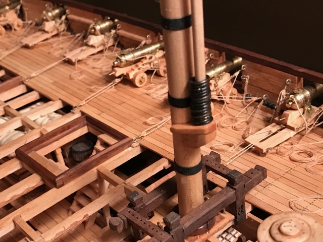
Here is what the main mast looks like today. I have completed the lower main mast and fighting top. The Main Topmast is mostly done. A bit more clean up, then I will work on the cross trees. I have a question regarding the mast caps. My assumption is they need to be aligned perpendicular to the mast itself rather than aligned with the fighting top. Since the main mast is raked at 8 degrees it is more pronounced. The cap that is shown in the photos is a temporary cap which will be replaced. The fighting top was based upon that shown in the Lee book and assembled following the Swan Series Vol 4. There will be a matching top in the fore mast. Once the top mast was shaped I used the mill to cut the groove through for the sheave. The sheave was turned in brass and a brass pin through the mast as axle. Once the sections are complete the mast will be unstacked and restacked as it is rigged. Also shown are the spanker mast hoops. I really wanted to make these out of wood shavings but found it beyond my skill to make rings that I liked. If I made them out of paper, I would have to paint them. If I was going to paint them I might as well make them out of brass. These were blackened after soldering and cleanup. I still am debating a bit on how many rings to actually put on the mast. I believe a hoop would have been tied to each of the same places as a laced sail which would be every 27" to 3 feet. I have 15 on here which would represent about a 27" spacing.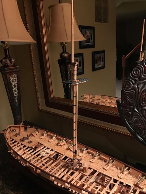
- 186 replies
-
- 24
-
-
Congratulations. I hope you enjoy yours as much as I have mine.
-
Much of this focus has been on planking. Yes, proportional divides can help immensely when setting up planking. You could also use just a fan ray. However, I completed planking on my Eagle many months ago. I still use the proportional dividers a great deal. So it is not just about planking. there are many instances in models where we need to divide a space into parts, or find the center. Yes there are many alternatives for each of these however a good set of proportional dividers come in handy in many areas outside of just planking.
-
This thread reminded me. I wanted to check my display case. When it was built, there was a very strong vinegar smell most of this was from the silicon glue in the case. However, when I built the case I allowed the small amount of heat that the LED's built in the lid to create an air movement from the base. I was hoping this would allow any acetic acid to vent out the top. Yeah, it does not smell of vinegar now! However it has been two years. At least I know it is working and my Connie is safe and sound. I highly recommend reading the linked article. It is very informative. While very little, if any lead is used in today's models, the acetic environment is probably not good for rigging. I know there are several threads where modelers will not use beeswax because of it's slightly acidic properties. The article is available on line - http://www.navsea.navy.mil/Home/Warfare-Centers/NSWC-Carderock/Resources/Curator-of-Navy-Ship-Models/Lead-Corrosion-in-Exhibition-Ship-Models/ The Navy focuses on the lead deterioration problem. Old ships have fittings made exclusively from lead. New ships, can have lead in smaller amounts in solder. It is the creation of acetic acid that ultimately causes the deterioration. Many woods, paints, caulks, glues etc can contribute to the creation of acetic acid. As a side note JerseyCity Frankie, the lead deterioration is a bit more complicated than keeping it free of O2. I am not a chemist either but find things like this fascinating: Excerpt from article: The chemical process is: Acetic and some other acids, in the presence of carbon dioxide, catalyze with lead to produce lead acetate and lead hydroxide. Lead acetate and lead hydroxide together react with carbon dioxide and form lead carbonate. Lead carbonate then releases acetic acid and the process becomes self-sustaining.(6) It is important to recognize that the formed lead carbonate is not just a substance clinging to the surface of a casting, it is the surface of the casting transformed to powder. For practical purposes, a portion of the lead is gone and lead carbonate is left in its place. The lead carbonate releases acetic acid which can continue the process until the lead part is progressively consumed from the outside, inward.
-
I am working out the spacing interval for spanker mast hoops for the Eagle. Nothing on this was documented or found in the wreck so I was looking at other period ships. I found an excerpt on the Constitution Rigging from "Constitution - All Sails Up and Flying" By Olof A. Eriksen. It refers to leveling the hoops on 27” spacing for the spanker. The Constitution’s Anatomy of a Ship has then spaced approximately 3’ on centers although the AOS is not considered very accurate. James Lee’s book, "The Masting and Rigging of English Warships" states the Spanker sail was either laced to the mast or laced to hoops, the latter using the lace holes to attach the hoops. He states that the lace holes above the reef points were at 30” intervals. I have also had advice that the hoops should be 4 to 5 feet apart. So should these be 27" or closer to the 5 foot spacing? I am not putting sails on the ship, so these will all be sitting on top of the spanker boom. Advice?
-
- 1
-
-
Brig Eagle by robnbill - 1:48
robnbill replied to robnbill's topic in - Build logs for subjects built 1801 - 1850
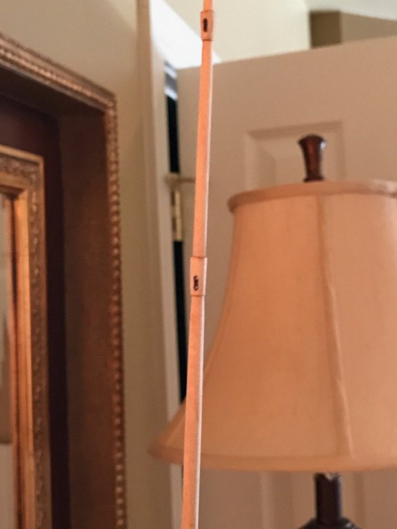
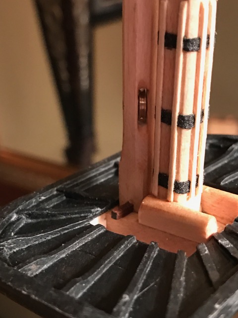
It has been a really long time since I made an update. While I have not been updating, I have been building. I started on the rigging with the construction of the lower main mast. I plan on using maple for the masting and walnut for the spars - although that is subject to change. I built the mast shaping jig and proceeded to make shavings. The first mast was a test and that was a great thing since it taught me a lot. Mostly about how to transition between the various profiles. Once thereal mast was roughed in, I made the cheeks and bibbs. Once these were fitted to the mast I banded it. I debated on whether to use rope wouldings, or iron bands. After much back and forth (in my mind) and getting great input (Thanks Glenn and Gary) I decided to use wouldings. While all the drawings of masts show iron bands, the speed at which they built the ship tended to point me toward them using rope wouldings. One of the points of discussion with Dr. Crisman was his use of wood hammock cranes. There was no evidence of these in the wreckage, but the Brown brothers always installed cranes on their ships. Given the time constraints, he felt they probably built them out of wood since it was readily available, quick to build and cheap. For me, this would also point towards them using wouldings since that would certainly be faster, cheaper, and readily available. Following along the same lines, I omitted the wood rings that would normally be put above and below these to protect the rope from wear. I have the trestle trees added and am beginning to work on the mast tops. I will build these based on David Antscherl's instructions for the Swan Class.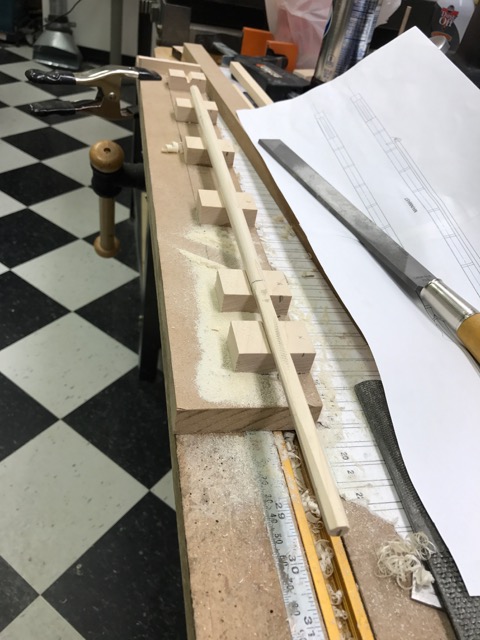

- 186 replies
-
- 23
-
-
I use mine all the time. They make easy work of finding the center of something, or dividing a length into any number of parts. The slide adjusts for the number of increments you want then presto. You can find centers without a measuring tape and division. Quickly, easy, and without math errors. I bought mine used on eBay and are Weems and Plath. These are a fine tool that cost nearly $200 new but I paid less than $70. A good set is solid steel and nothing to wear out. The case is worn but the instrument is in perfect condition. I never knew how valuable a tool it was in the workshop until I got one.
-
One other note on making a case. The US Navy found that having air tight cases caused their models to deteriorate. This was from outgassing of the various products used in the ship construction as well as the case. It does not have to be much air, but some fresh air should be allowed through the case in amounts to allow the outgassed chemicals to leave.
-
Congratulations! There are many variations on cases here. I would look at completed model photos. There are also a number of threads regarding cases. It really depends on your tastes, where you plan on displaying her, and the size/scope of case project you are looking for. There are frame kit suppliers such as Model Expo where you provide the finishing and glass/plexiglass or you can go the entire custom case route from scratch. One suggestion I have is what ever route you decide, don't make the case too small. You need to have room for the ship to look at home there. Congrats again. The first ship is a huge milestone.
-
Thanks Professor. I appreciate all your kind words. I developed a love/hate relationship with the Mamoli Plans. Once I got into the swing of things I tended to use the plans as suggestions for the next phase of building. In most cases they were correct. Other areas I would jump around a bit. As I would do with anyones plans, I would read ahead and plan my attack on an area. If I followed the Mamoli plans exactly, it would have produced a ship but not quite the one I wanted. There were a few errors in mine that (I believe) were corrected in later revisions. One area that comes to mind it the Spanker. The plans had the mast top terminating in space just below the fighting top. However, it actually mounted into the underside of the top. A minor point. There was no instruction manual per se. Each of the plans would have a column of instructions associated with the drawings. The written instructions were poorly translated. I would read these through because they did give a good sense of what parts numbers they were referring to. By far the main benefit of the Mamoli plans were their tables. This is where they would tell you what the piece was to be made of, i.e. the size of lathe and type of wood. It would also tell how many of each would need to be prepared. However, once I got into the rigging, The plans were very well done. While there were places I made decisions in the rigging that did not follow their plans, I still found what they wrote to be very well done. There is a thread under the rigging area of this forum where I wrote how to interpret the instructions for rigging. I can't tell you these plans were better or worse than others. I did not have any other plans for the ship except the Navy's or the AOS. So I can't compare or contrast other builders materials. As far as a cut away version, that will be cool. You might also want to look at Gene Bodnar's build log of his Constitution. He took the AOS and used it to build a Connie that was built in sections that could be pulled apart to see the interiors of the ship. His log would be on the Model Ship Builder forum. Bill
- 335 replies
-
- 3
-
-
- Constitution
- Mamoli
- (and 3 more)
-
location of stud sails (stuns'l) when stowed
robnbill replied to timboat's topic in Masting, rigging and sails
On the Connie the lower stunsail booms were attached to a hinge/pivot point on the forward end of the Channels. There were two per side on my plans. I believe these booms were also used in handling boats.