robnbill
-
Posts
841 -
Joined
-
Last visited
Content Type
Profiles
Forums
Gallery
Events
Everything posted by robnbill
-

Brig Eagle by robnbill - 1:48
robnbill replied to robnbill's topic in - Build logs for subjects built 1801 - 1850
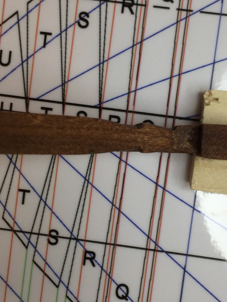
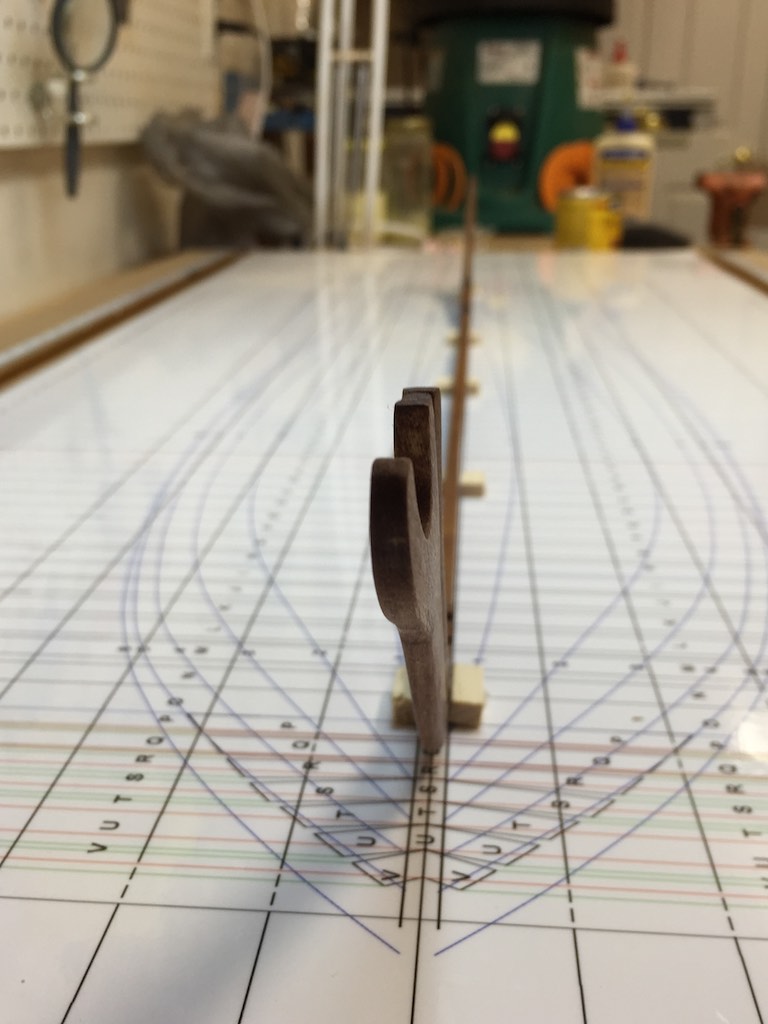
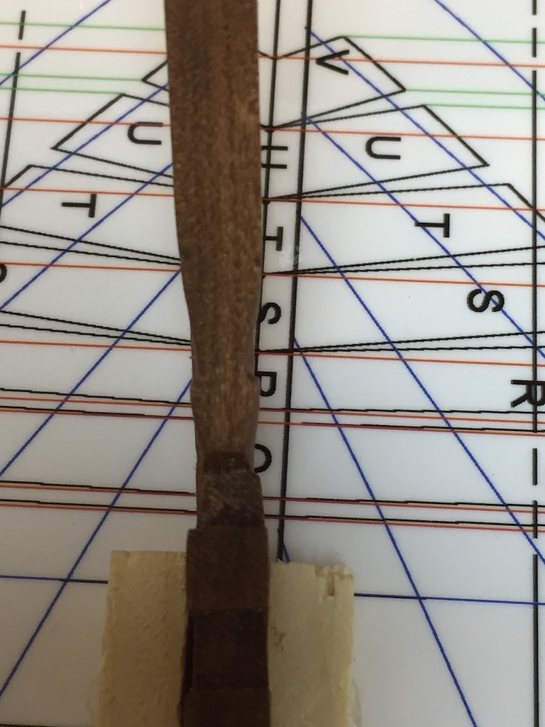
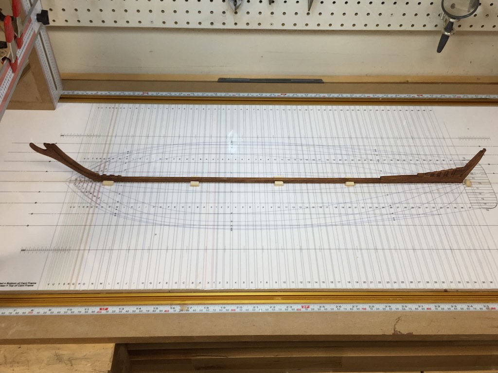
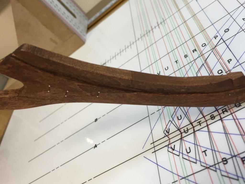
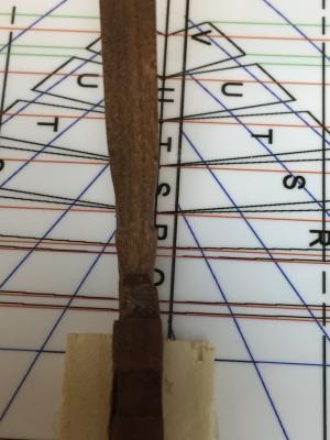
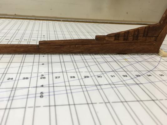
Before I get into the keel assembly I should explain my sources of information. First, there is a 1984 PhD dissertation by Dr. Kevin Crisman found on the Texas A&M Underwater archeology Site. Great reading. This was expanded by Dr. Crisman in a book called "The Eagle, an American brig on Lake Champlain during the War of 1812" published in 1987. This was followed last year by a chapter on the Eagle in "Coffins of the Brave" also edited by Dr. Crisman. There is also a great practicum developed by Gene Bodnar on scratch building a version of the Eagle. These documents along with my CAD drawings and supplementary communications with Dr. Crisman on various aspects of the ship are the materials used in this build. I have completed redoing the keel assembly. I went through all of Dr. Crisman's materials noting dimensions carefully. Where text differed from sketches, I followed dimensions explicitly called out in the text. A few things I found very interesting. First, as I followed the sizing between the various parts on the bow assembly it fell into place that the apron was shaped not only to support the cant frames but also to support the side planking leading to the rabbet. So the rabbet was wider here to allow for this. The assembly was also shaped. The top of the bow and the apron would be 18". The forward part of the cutwater would be 6" and the keel where it met the bow would be 8". This gradually increases to 12" before reversing at the deadwood. This solved some of the perplexing transition questions I had with both the bow and stern. The stern has notches cut for the heels of the futtocks in the half frames. On the ship, these were a bit sloppy with the notches on one side of the keel deeper and wider than the other. This is more a factor of the speed at which they built the ship and shipwright skills. Dr. Crisman goes on to explain that the lower deadwood had a great deal of shaping done with great forethought. It starts out at 12" on the forward end and 8" on the stern (following the shape of the keel below the rabbet and 15" above. This change follows the rabbet as it rises towards the stern and would have provided a stable base for the garboard plank. Since the frames will be white rock maple, I stained the cherry for contrast. Prior to staining it, I sanded it to 220, the burnished it with steel wool. I still have to add the fishplates. Note in the photos, the plan the ship is sitting on has my old framing numbers. As I worked through the various details called out in the materials, I found my numbering scheme was off. Frame X in the materials is actually a ½ thickness square frame. Once I made this change all the details mapped out by the materials aligned perfectly. I also changed the number of cant frames in the bow to 6 to following the materials.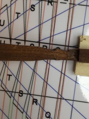
- 186 replies
-
- 13
-

-
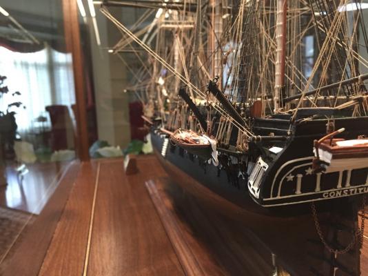
Congratulations! She looks great. Outstanding job. You should be very proud. Many Connies are started, few are completed. Well done!
- 1,756 replies
-
- 2
-
-
- constitution
- constructo
- (and 1 more)
-
Brig Eagle by robnbill - 1:48
robnbill replied to robnbill's topic in - Build logs for subjects built 1801 - 1850
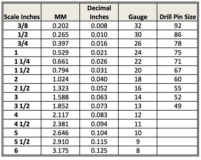
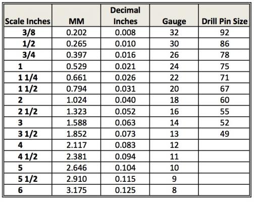
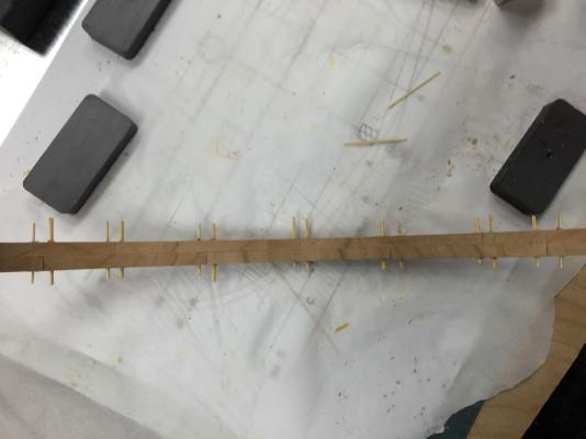
I completed relofting the frames to the as-built spacing. I have decided that I want to redo my keel for a number of reasons. First, I want to make the deadwood more in line with the research materials. In those they show the stern half frames to only have half of the frame slotted into the deadwood. In addition, I want to re pin the keel with brass scaled to that in the materials. In that vein, I put together a chart mapping the scales for 1:48 pin sizing ½" through 6". This maps the scale sizes through Metric, standard, wire gauge, and micro drill sizes. I took brass wire and pinned a scaled 18" beam with ½ through 3" pins as a reference. I stil need to refine my stern counter timber framing and plan on doing that tomorrow or later today. Then I am ready to start making sawdust.
-
Until you get her in a case you might want to borrow some ropes from the Movie theater to keep everyone away from her. I think I got more nervous every day the ship was not in a case. She is looking great. You (and your admiral) should be proud. Many Connies are started but few finished.
- 1,756 replies
-
- 3
-
-
- constitution
- constructo
- (and 1 more)
-
Brig Eagle by robnbill - 1:48
robnbill replied to robnbill's topic in - Build logs for subjects built 1801 - 1850
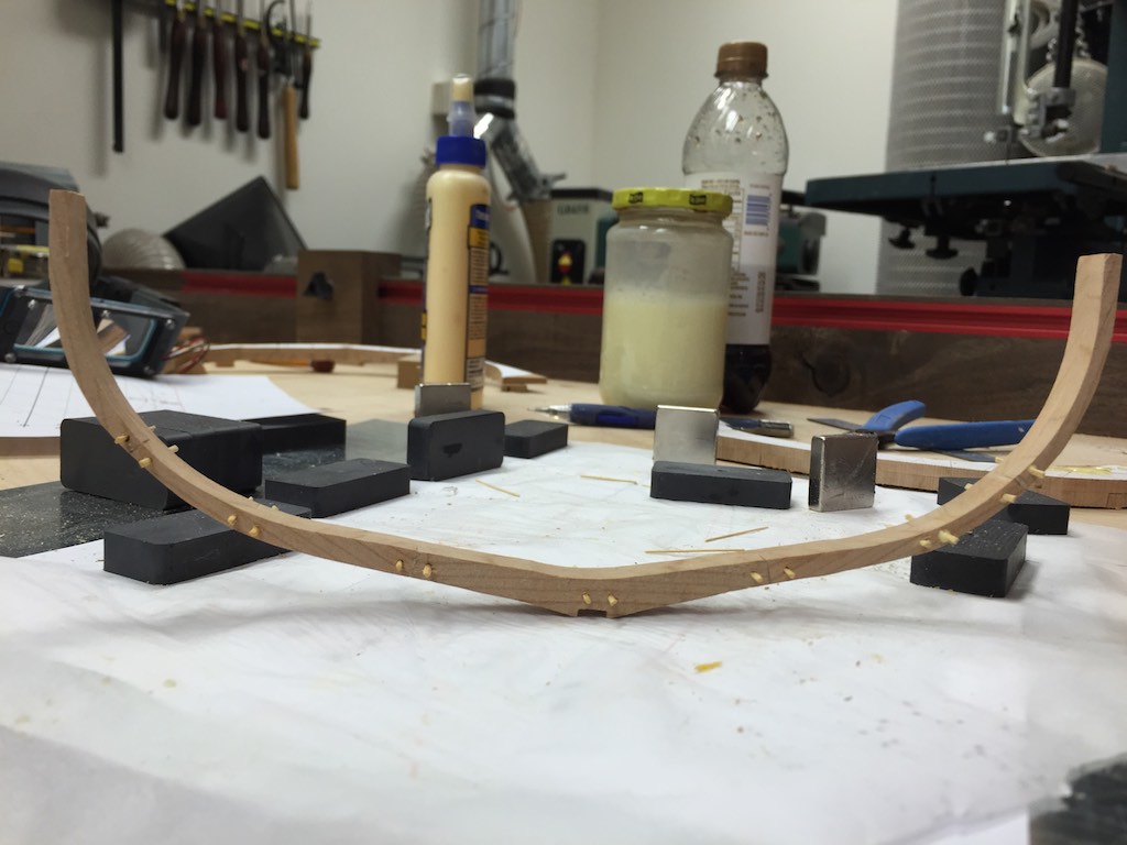
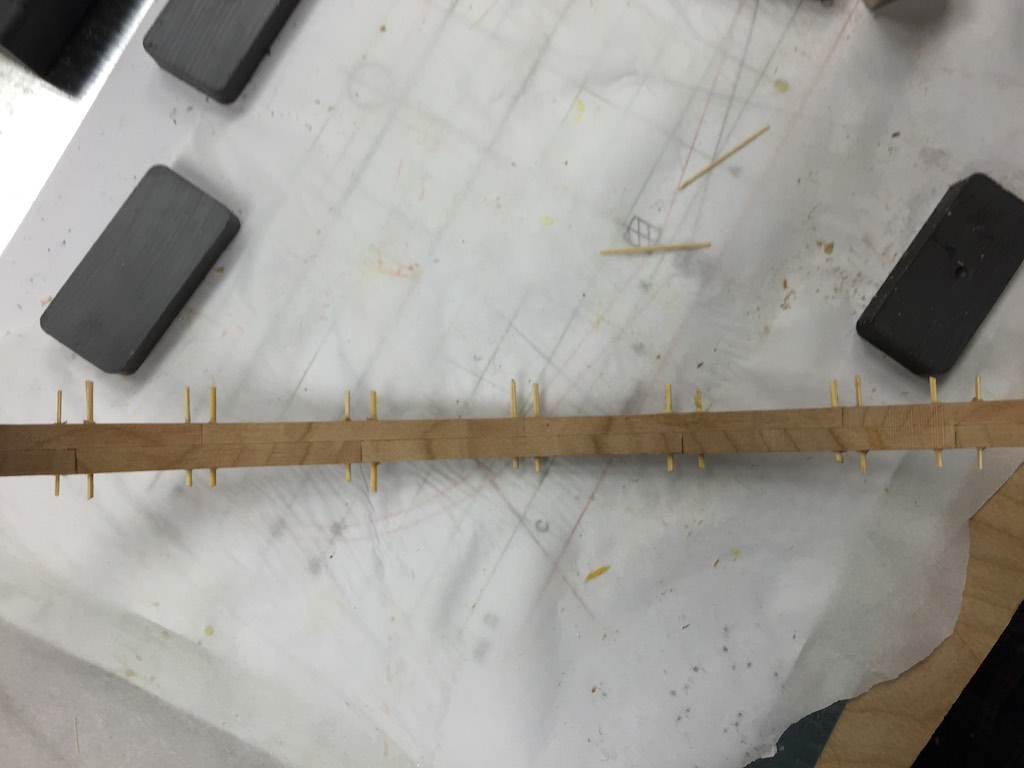
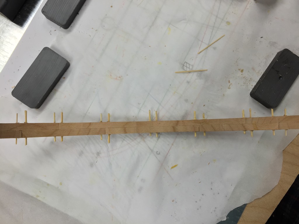
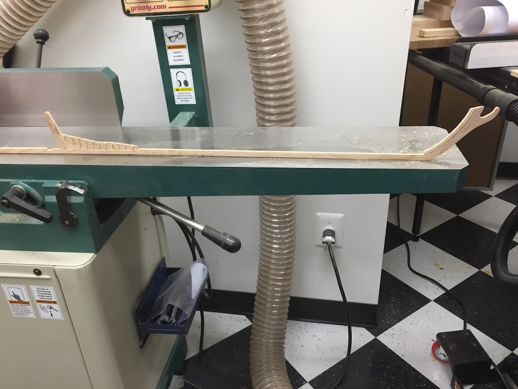
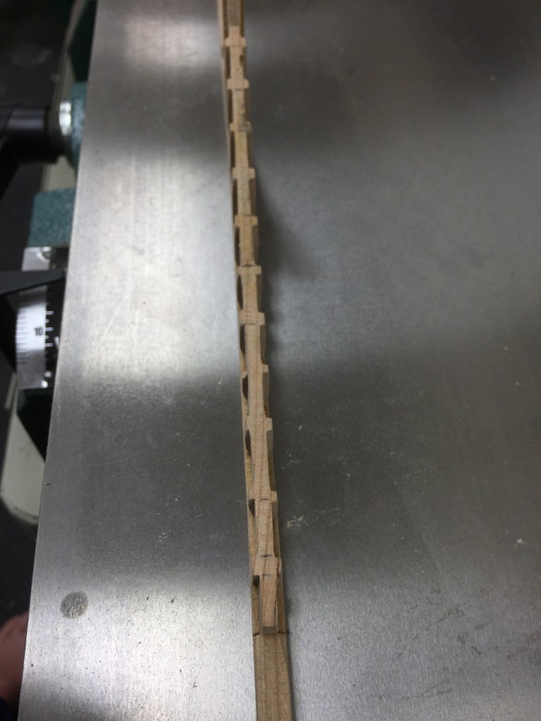
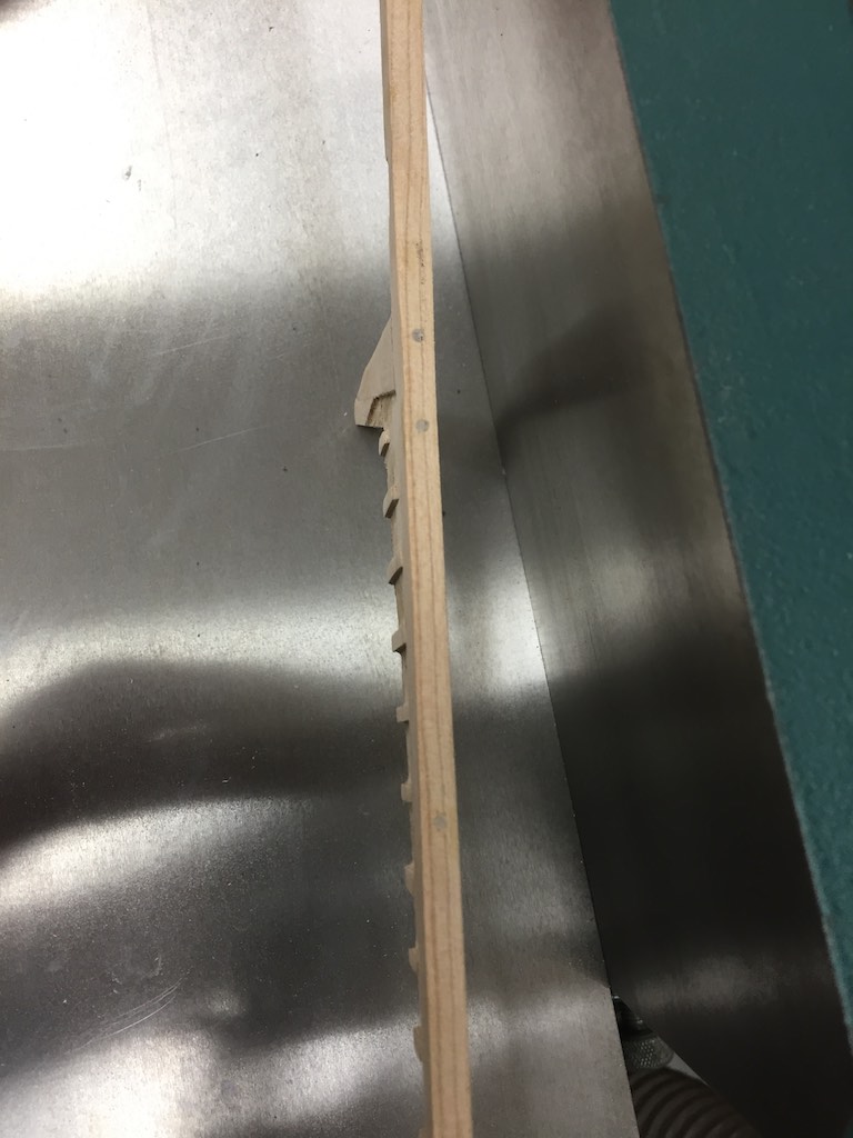
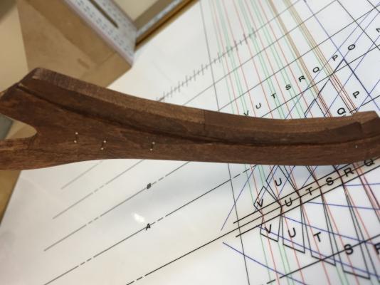
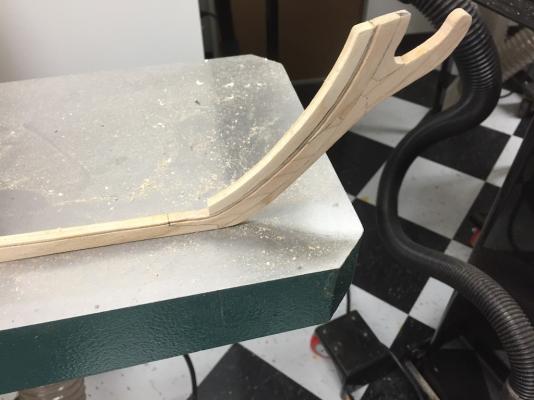
I used hot glue to glue the keel blocks to the gantry jig. This allowed me to keep them very small and still hold the keel adequately. I also removed the keels tail since it is not required with the gantry. After this was done, I used some cherry to build a test frame. I wanted to go through the process from cutting the raw wood to having the frame ready to mount to the keel. I chose Frame X as my test subject - Bwhahaha. I used a band saw to cut the frame out once the glue dried. Then I used the Oscillating Sander to remove the excess wood to the line for the frame. I used the Scroll saw to trim the keel slot and cleaned it up with a file. Once that was done, I used a #57 drill to drill the drift holes. I did this in the drill press since it allows me to keep the frame at a specific angle during the drilling. In this case, of course at 90 degrees. I used the Byrnes drawplate to make bamboo pins. These I glued into the holes. I have not yet trimmed these back since the glue is still drying but I did try a test fit with the gantry. Since this is a test frame and also made of Cherry, this will not go any further than trimming the sanding the pins. I will instead move on to completing the new lofting set then start working on the frames at the stern first. My plan (always subject to change) is to start the frames with the last full square frame. Then work back to the stern through the counter timbers. Once the stern is complete, I will head to the bow, per Mike, Gary, and Ray's excellent advice. Since this is my absolute first attempt at making a frame, please comment if you see I am doing something stupid. Thanks,


- 186 replies
-
- 12
-
-
That would be a great addition to your Connie. Enjoy Hawaii. Save some for us. We are headed there in the Fall. We will be catching a ship there to Sydney.
- 732 replies
-
- 2
-
-
- constitution
- model shipways
- (and 1 more)
-
Rich, I have the CAD drawings for the 25 Captain's Gig and 28' Whaleboat. I also have the drawings of the 34' launch. These could be scaled to your model, but it would mean scratch building them. Let me know and I will get them to you.
- 1,756 replies
-
- 2
-
-
- constitution
- constructo
- (and 1 more)
-
Brig Eagle by robnbill - 1:48
robnbill replied to robnbill's topic in - Build logs for subjects built 1801 - 1850
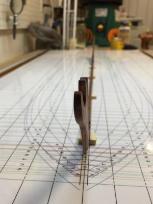
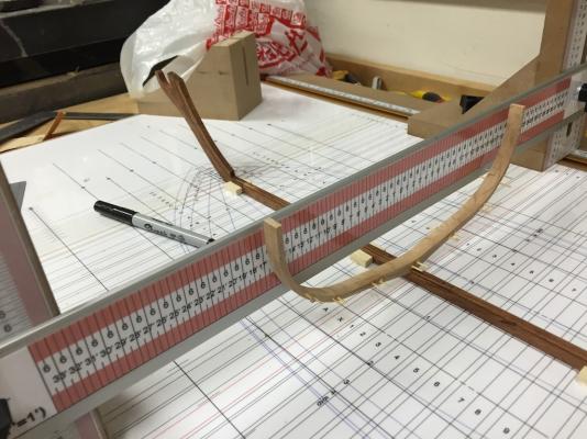
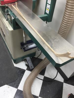
I will be but it is not yet. I ran out of double sided tape yesterday so I did not finish securing and aligning the scales to the gantry. Once that is done, I will use those to align the build board plan and stick it down. Then I will make the appliances to attach and hold the keel secure. I just set it on the gantry for a photo op yesterday. -
Brig Eagle by robnbill - 1:48
robnbill replied to robnbill's topic in - Build logs for subjects built 1801 - 1850
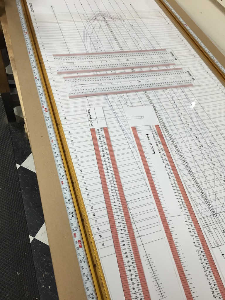
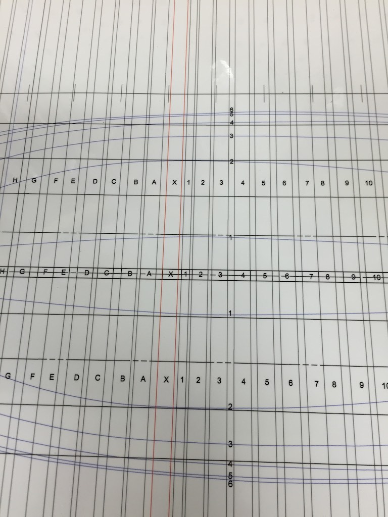
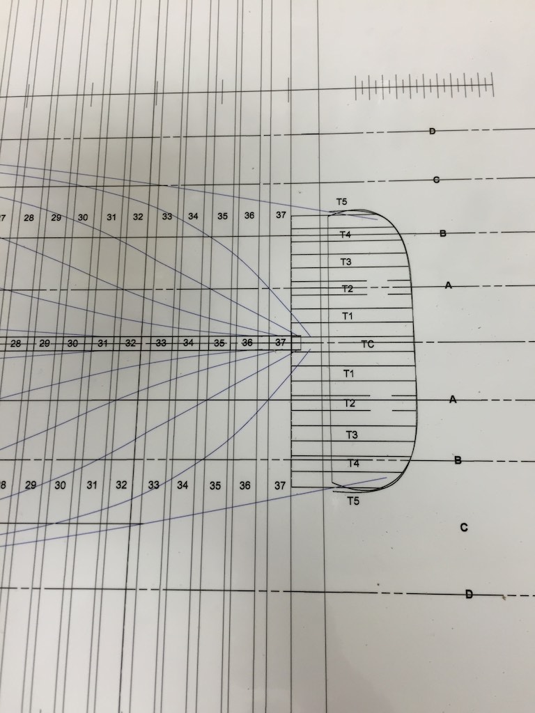
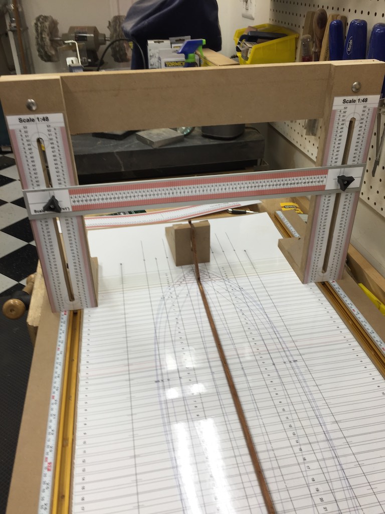
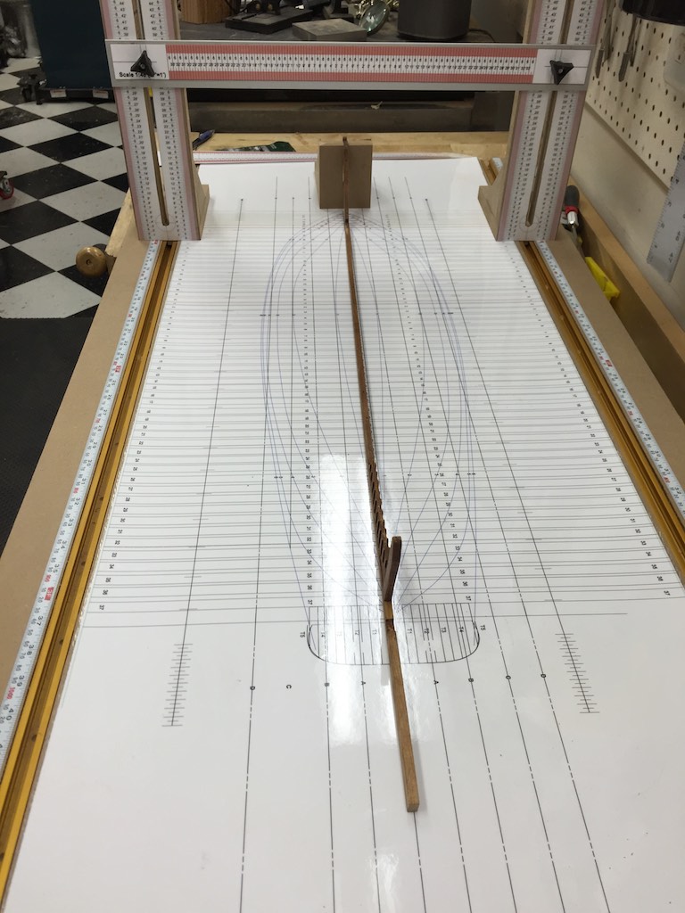
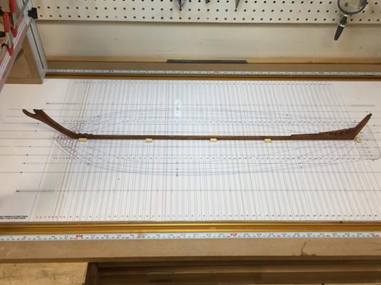
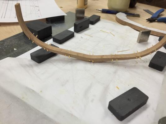
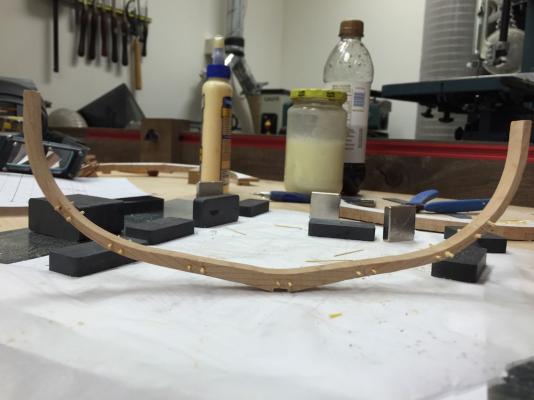
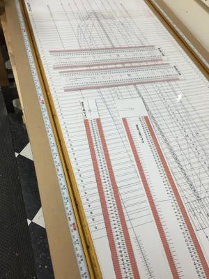
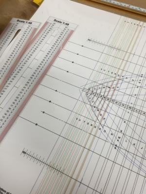
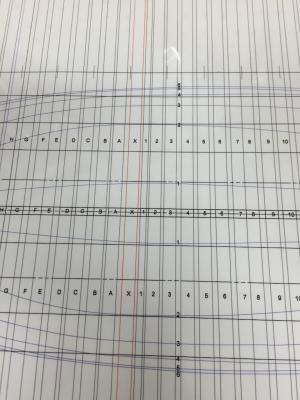
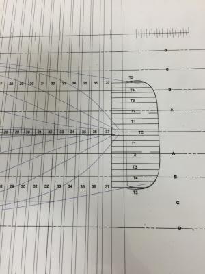
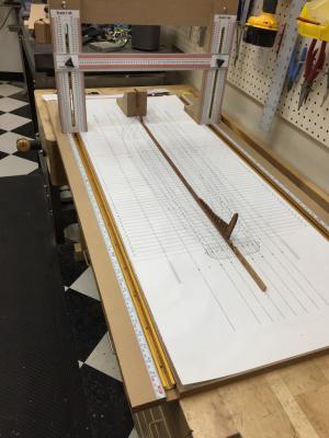
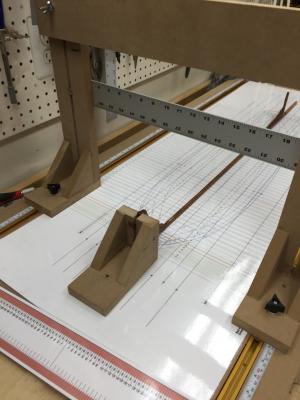
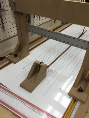
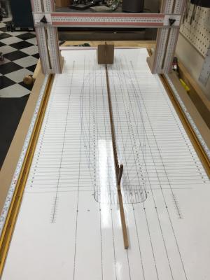
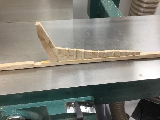
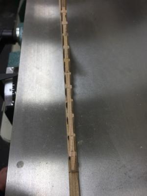
I decided to jump course a bit on the build. The practicum constructs a double decked framing jig. I actually cut all the parts for it then decided to change methods. I had looked at a number of builds which used a Gantry Jig to assemble the models. I liked the idea and it certainly provides more access to the frames. The order of construction changes a bit since the practicum starts in the middle and works toward the ends. With the Gantry, you work from the ends toward the middle. One aspect of using the gantry is the ability to trace any of the ships curves to the frame during construction. So I combined the half breadth, the keel and the frame alignment plans into one master which will be underneath the build. This should allow me to check the alignment of a frame against any of the curves quickly. The gantry is complete. I still have to attach the scales to all of the members. Once that is done, I will use them to finalize the alignment of the master plan which will be on the bottom of the jig. I had the plan printed and laminated so it will be more protected as well as keeping glue squeeze out from damaging it. Once all the scales and plans are affixed, I will create the holding and clamping surfaces to mount the keel and clamp cant frames etc. So framing will commence soon. Below are a couple of photos of the scales and master plans after getting them back from lamination. These are sclaed to 1:48. This shot shows the bow. The red lines are where the cant frames hit the keel. The green lines map where they intersect the outside waterline. The black vertical lines are the square frames. Midsection and Stern This shows the gantry with the keel assemble temporarily on the plan. The bow is being held by a temporary appliance. The top horizontal member will have the scale laying toward the bottom of the shot attached to it. The lower horizontal member will slide up or down. I made it out of an aluminum straight edge. The forward side has inches on it. The back side has the 1:48 scale. It is narrow enough that it will pass through the spaces between frames. By using a square on the master plan, lines can be traced upwards through the model. The T-Slots allow the gantry to be moved easily along the model It can be used as well as a clamping brace. In addition, the T-Slot also allows other appliances to be held and moved as they require. I also will be attaching other blocks through the mater plan via hanger bolts with slots in the appliances allowing easy adjustment. The measuring strips are marked in both inches and centimeters. This also will confirm that the frames are square as they are moved around the frame.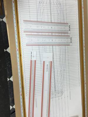

- 186 replies
-
- 11
-
-
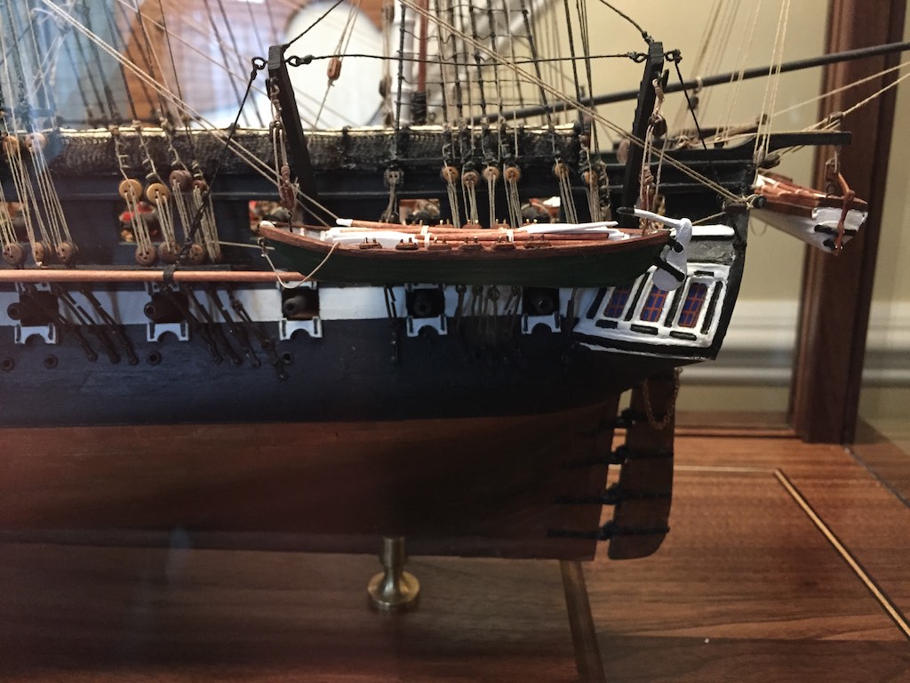
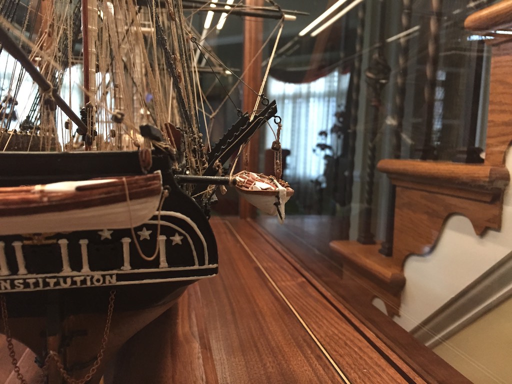
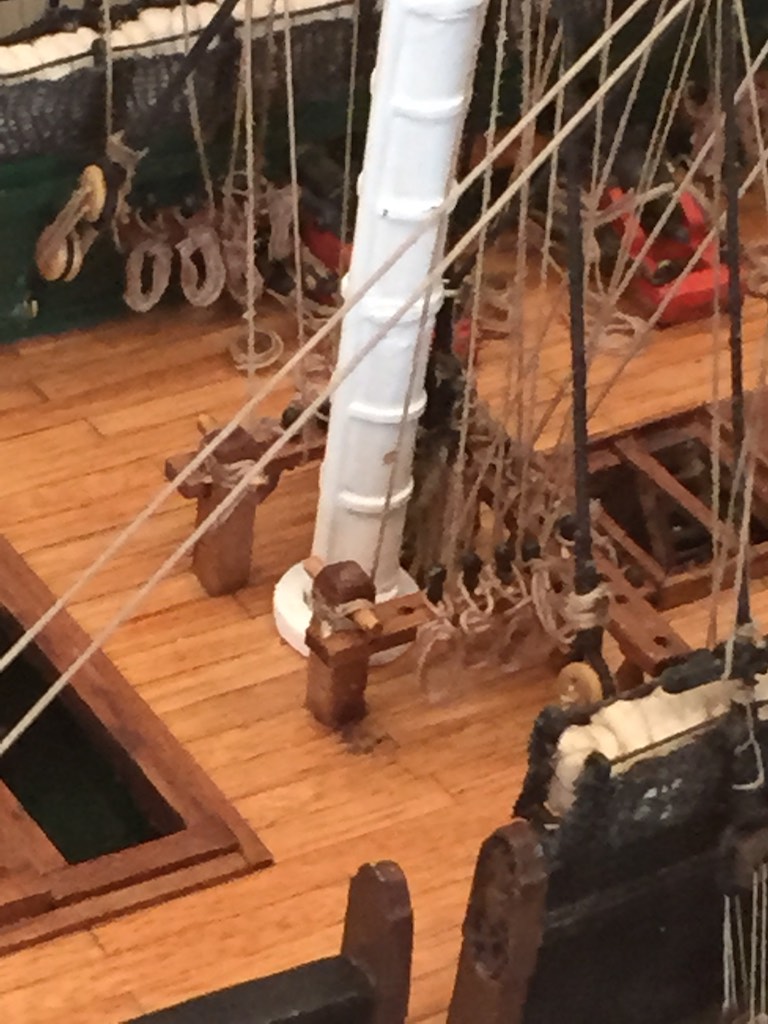
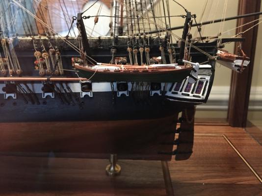
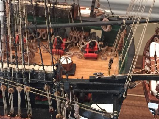
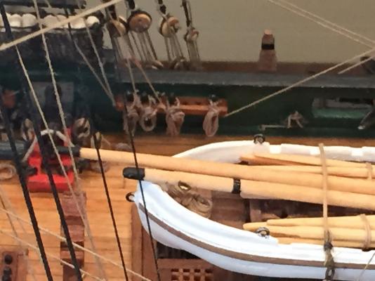
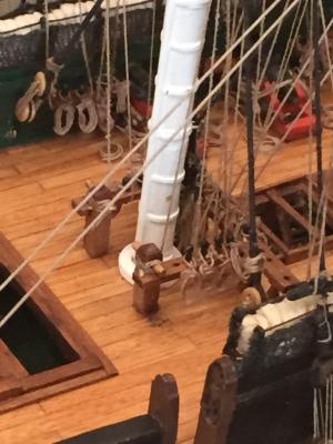
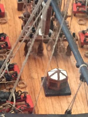
I have mine sort of in between. Here was my thinking. I have my cannons run out ready to fire. As such, that means the ship is moving toward if not already in a battle posture. My understanding is during a battle the ship's boats would be lowered and towed astern to clear the line of fire as well as try to preserve the boats, which seemed to have a short shelf life. That was also my reasoning in having the rudders attached to the sterns rather than unshipped. Of course, I also like the look. So I just played with the location until I liked the look. Here are some photos. I chose the white and green based on a Bainbridge note.

- 335 replies
-
- 11
-
-
- Constitution
- Mamoli
- (and 3 more)
-
One other thing that I would do, is after I hung a coil, I would take something, usually the point of my tweezers, and would place it in the lower part of the coil and tension it downward. This allowed me to make sure the loop was seated well over the pin, and I could adjust the hang and final shape of the coil. It is after this that I would decide if I needed to place any additional glue behind the coil to hold it in the correct position. The vast majority of the coils were hung without needing any additional glue. Since all of the coils were glued initially just at the pin, it was pretty simple to swing a coil up with tweezers and apply any additional glue to the back of the coil, then use the tweezers to push it down into the position I wanted it to stay.
- 1,756 replies
-
- 4
-
-
- constitution
- constructo
- (and 1 more)
-
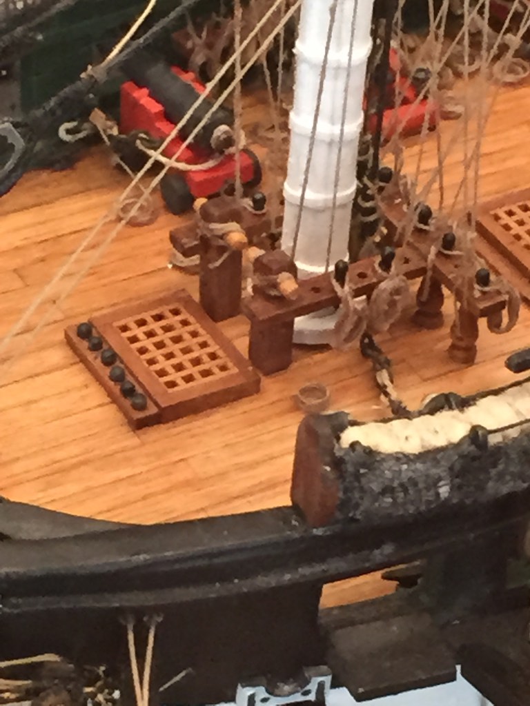
Here you are. With only a couple of exceptions, I only placed coils where I had rope terminating on the pin rail. The exceptions were on the stern fife rail where I had some open space that I thought needed to be filled. I did not attempt to add enough coils to actually run a line, I also did not want to cover the ship in coils, and I wanted the coils to be similar but not too so. Of course I made all the coils off the ship. I used the Beeswax/Turpentine mixture to wet them. I wound the requisite number of coils around a dowel then gently pulled it off and shaped it. I made sure that as I shaped the final loop going over the pin, I hid the other end since theoretically the other end was supposed to be up in the rigging somewhere. Then it was a matter of touching glue to the pin area and lowering the loop over the pin head and shaping how it hung. I did have to use some additional glue behind some of the coils to get them to hang just right.


- 1,756 replies
-
- 6
-
-
- constitution
- constructo
- (and 1 more)
-
Sorry, I meant to saw hawser, not bower. The reason I ask was the Connie was not fitted for chain until probably the 1850's. The switchover from hemp to chain required a huge change to the ship including the addition of iron hawse pipes as well as chain lockers etc. The Capstan also had to be modified to handle the chain links. Anyway, she certainly has chain now. One reason she still does is the inordinate expense to modify the ship back. There is an interesting article on this at the Museum site. The link is below. http://156.112.98.23/USSCTour/manuals/ConstitutionAnchorChain.pdf
- 1,756 replies
-
- 1
-
-
- constitution
- constructo
- (and 1 more)
-
Rich, this is looking great. Why did you choose to use the chain as an anchor bower?
- 1,756 replies
-
- 2
-
-
- constitution
- constructo
- (and 1 more)
-
I can see it now. 300 hundred years in the future, an archivists is carefully restoring a model of the Constitution and they find the magnetic media hidden behind the windows. So carefully they extract the delicate plastic and analyze it and wonder what an Excel file is, and what religious connotations the numbers meant to the builder.
- 1,354 replies
-
- 5
-
-
- constitution
- model shipways
- (and 1 more)
-
Brig Eagle by robnbill - 1:48
robnbill replied to robnbill's topic in - Build logs for subjects built 1801 - 1850
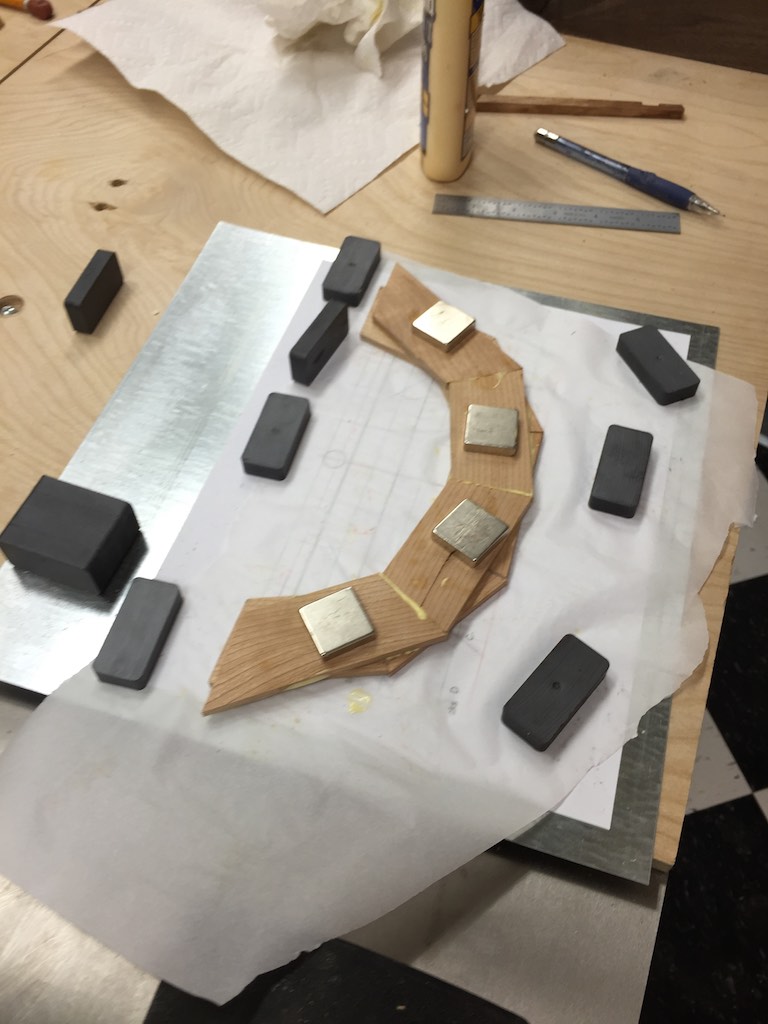
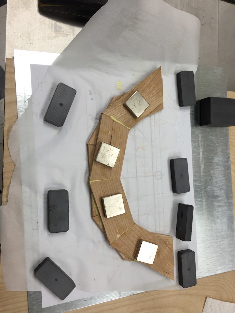
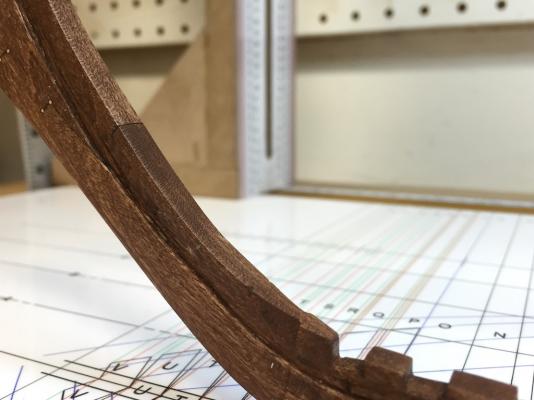
Once of the decision points in the scratch build is the type of woods to be used. While I like boxwood, the chances of needing to go through massive amounts of wood as I fix mistakes necessitate looking for a less expensive alternative. I wanted a hardwood, but also wanted a variety of wood to better show off the ship. I chose cherry for the keel and keelson assembly and rock maple for the frames. As I move further into the model I will make the decisions for the remainder of the ship. I wanted to jump into the build and make sawdust. So I picked up some cherry and maple from my local supplier and milled them down. I will start with the keel assembly, then move on to the building jig and re-lofting the frames. Here are photos of the keel assembly. I have been trying Dave S's technique for the jointing by cutting the first part, then cutting the matching piece by placing black tape over the second piece, clamping the two pieces together, then cutting the tape around the joint with and Xacto knife. This is then used to cut the second half of the joint. I also used a black wax pencil to mark the interior of the joint so the glued up joint would show well. I did not like the first attempt at the deadwood, so I redid the keel and deadwood. Tomorrow, I will start working on the building jig as well as testing stain. While I do not plan on staining the entire model, I would like the cherry to be a bit darker than it is currently. It would darken over time, but I would rather not have to wait 10 years. I think the darker cherry would look nice against the maple - providing I find a satin I like.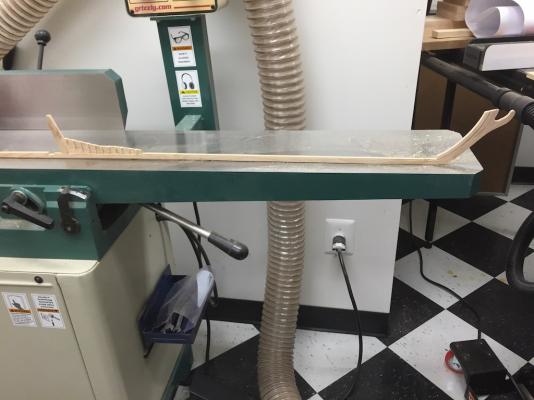

- 186 replies
-
- 14
-
-
Brig Eagle by robnbill - 1:48
robnbill replied to robnbill's topic in - Build logs for subjects built 1801 - 1850
There are a number of steps to get this model ready to build. The first is to collect the general ship plans. Those are the Sheer plan, the Half Breadth, and the Body Plan. Then these need to be enlarged to the correct scale where ¼" is equal to a foot. These are used to develop all other plans. These plans all come from Dr. Crisman's materials. In addition to the dissertation, he wrote a book, which is a slight expansion of the dissertation and there was a book edited by Dr. Crisman published last year by Texas A&M University that called Coffins of the Brave, Lake Shipwrecks of the War of 1812. This material expands that found in the previous work as well as makes some slight changes to the ship based upon later research. Rather than manually attempt at enlarging and copying, I decided to pull all of this into my CAD program and redraw them. Since all the existing plans were published in books, the enlargements made the lines fat, as well as some basic inconsistencies between the various plans primary due to enlarging artifacts . By redrawing these in CAD, I was able to place them all accurately in scale and have very clean drawings from which to work with. Over the last 9 months I have refined these drawings and was lucky enough to get Dr. Crisman to review them and provide comments which I was able to incorporate. As a result I have ended up with drawings that are consistent and accurate across all views and include the latest information from Dr. Crisman. Some of the changes base upon the previous plans include replacing the ship's wheel with a tiller, adding a capstan aft of the main mast. In addition, I decided based upon the "in for a penny, in for a pound" philosophy to build the frames aligned on that found in the wreck. This meant that the frames are not evenly spaced across the ship. Due to the exigencies of the war and the speed this needed to be built, some of the basic premises of ship building were ignored during the build. Green wood was used, knees were not used, rather the deck clamps were beefed up. This was not a ship designed to last. A case an point was soft, rot prone woods were found used deep in the ship. To replace them would mean massive overhaul of the ship. Also, Dr. Crisman's drawings had been misinterpreted to show a double rail. What he was trying to show was a single rail with hammock cranes mounted to the top. While this will be an admiralty build, and thus not fully planked, I have not yet made the decisions on whether to rig it or not. I am also interested in showing the probable berth deck layout. Other than the number and location of deck support columns, remains of a shot locker and pump locations, little hard evidence remains of the layout. However, layouts of similar sized ships both from the same builders and other period ships are known and can be used to produce a fairly solid layout of the deck. How much of this can be adequately shown in my model has yet to be decided. Once I had fairly solid drawings, I did a complete lofting based strictly on the practicum. However this was based on frames being equidistant. When I made the decision to adjust the frames to the "As-Built" layout and revised the drawings accordingly, this meant I needed to re-loft them. I wil continue to provide a number of posts until I will be current with my build. -
Brig Eagle by robnbill - 1:48
robnbill posted a topic in - Build logs for subjects built 1801 - 1850
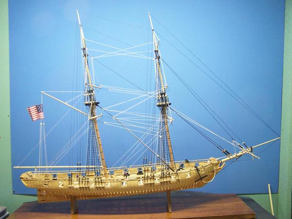
Once I saw the end approaching to my USS Constitution build I started looking for my next project. I was looking for something that would hook my interest in both the construction as well as the history. I wanted something challenging that would also push my skills. I found and downloaded Gene Bodnar’s Practicum on the USS Brig Eagle. This is a plank on Frame Admiralty build that can be fully rigged or left unrigged in Admiralty style. The Eagle was built at Vergennes, Vermont between July 23rd and August 11th of 1814 by shipwright Adam Brown. An amazing feat in itself when you consider it generally took many months to build a ship of this size and the shipbuilders who built this ship did it in only 19 days. But time was of the essence. The wreck of the ship was found in the freshwater mud off Lake Champlain and fully documented in the dissertation. It was a built in 19 days for the war of 1812 and was responsible in large part for the defeat of the British fleet in the Battle of Plattsburg Bay. However it was built of green wood and began to rot almost as soon as it was completed. After the war it was stripped and mothballed and eventually sunk where she was mothballed. The practicum is a detailed instruction for taking the basic ship's plans and working through the lofting process to the completed build. This modeling project at 1/4" = 1' scale is based on a Masters Thesis and plans by Professor Kevin J Crisman of Texas A & M University. Here are some brief notes on the Eagle from the Texas A&M Nautical Archaeology Program site. The United States Navy brig Eagle was built at Vergennes, Vermont, and constituted the final addition to Commodore Thomas Macdonough's War of 1812 naval squadron on Lake Champlain. The 117-foot-long hull was constructed and launched by master shipwright Adam Brown in only 19 days during the summer 1814. Outfitted with two masts and 20 cannon, and manned by a crew of 150 men, the brig participated in Macdonough's defeat of an invading British naval fleet at the Battle of Plattsburgh Bay. The Eagle was maintained for several years after the war, until her timbers became decayed and she was abandoned by the Navy in 1825. The submerged and partially-dismembered wreck of the Eagle was discovered in 1981 near Whitehall, New York. A two-year archaeological study of the vessel was sponsored by the Champlain Maritime Society, during which time the dimensions of the hull timbers were documented by divers. Archival research was also conducted on the history of the warship. Wreck plans were prepared from the measurements recorded by the divers, and the techniques of hull construction employed by Adam Brown were examined. The wreck plans and contemporary construction information were then used to reconstruct the original appearance of the brig. The design and assembly of the Eagle were graphically depicted in the form of hull lines, construction plans, and rigging plans. The hull of the brig was compared to other War of 1812 warships on the oceans, and on Lakes Erie, Ontario, and Champlain. The evaluation of the hull and the comparison with contemporary vessels have led to the conclusion that the Eagle was specially designed for accelerated construction and a career on the shallow, protected waters of Lake Champlain. This is attractive because it will be a challenge that will require lofting my own plans as well as building my first Plank on Frame ship. It is also supported by a detailed practicum as well as the extensive dissertation. While it is being built by a small number of modelers on Model Ship Builder, Gene Bodnar, the developer of the practicum is very active on the boards. Fully rigged the ship’s dimensions will be: L = 45" H = 31 1/4" W = 6 1/2" Here is a photo from the practicum.
- 186 replies
-
- 19
-
-
That explains it. I thought it might be for a block or something to go under the barrel for elevation but the steps didn't seem to align for that. Using them as fulcrums makes total sense. Start on the lower one, raise the canon a bit, the next sailor take the next step. Thanks!
- 113 replies
-
- 2
-
-
- constitution
- mamoli
- (and 1 more)
-
But even those were designed to impress. We still use our ships/Navy to impress. Early psychological warfare.
- 113 replies
-
- 2
-
-
- constitution
- mamoli
- (and 1 more)
-
I assume that since everything on a ship had a function, the steps on the carriage also did. What were they used for?
- 113 replies
-
- 1
-
-
- constitution
- mamoli
- (and 1 more)
-
For mine, I looked at Tulle but the scale was wrong. SO I took the netting in the Mamoli kit and dyed it black. This stretched between the hammock cranes looked okay.