robnbill
-
Posts
841 -
Joined
-
Last visited
Content Type
Profiles
Forums
Gallery
Events
Everything posted by robnbill
-

Tapering masts, spars and yards
robnbill replied to bryanc's topic in Modeling tools and Workshop Equipment
You would need to use a very small spokeshave. There are a number of techniques that can be used to round the masts. One is to flatten the sides evenly to the correct diameter, then round the corners out. Another method is to turn the dowel in a drill or lathe and use files and sandpaper to bring them down. This is the method that I use. Of course, for many masts and spars, you end up doing a bit of all of the methods since there are flattened sections of the spar and other areas where it tapers down to toothpicks. I would suggest that you go to the hardware store and purchase dowels slightly larger than you need and start experimenting with the various methods until you find the one that works best for you. This will also give you spare material should you break one. If you do a search of this forum using key words you will find examples of all of the above and more. -
Oh no........! Not the stern windows debate again.
- 1,756 replies
-
- 2
-

-
- constitution
- constructo
- (and 1 more)
-
Very interesting discussion. I will follow with interest.
-
That is a great point. I don't think I have seen anyone do that. You could really add another dimension to the viewers by doing that. The key will be figuring how to do it with the right balance. I am looking forward to continuing with watching your build.
- 113 replies
-
- 1
-
-
- constitution
- mamoli
- (and 1 more)
-
Well here is a Connie connection for M&C from IMDB. The French frigate "Acheron" was modeled after the USS Constitution ("Old Ironsides"). The film crew spent quite a bit of time taking pictures and filming the Constitution. The images were then digitized to make the movie. Originally based in Providence, Rhode Island, The HMS Surprise was actually the HMS Rose, a reproduction tall ship built in 1970 at Lunenburg, Nova Scotia by Smith and Rhuland Ltd. The film crew made several alterations to its design to match the 1802 design of the HMS Surprise. The Rose/Surprise has been at the Maritime Museum of San Diego since 2004, but in previous years the HMS Rose was available for tall ship cruises.
- 1,756 replies
-
- 3
-
-
- constitution
- constructo
- (and 1 more)
-
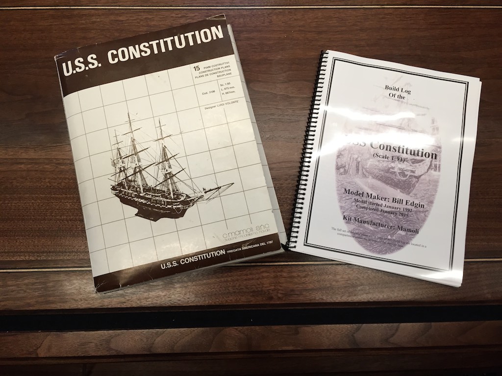
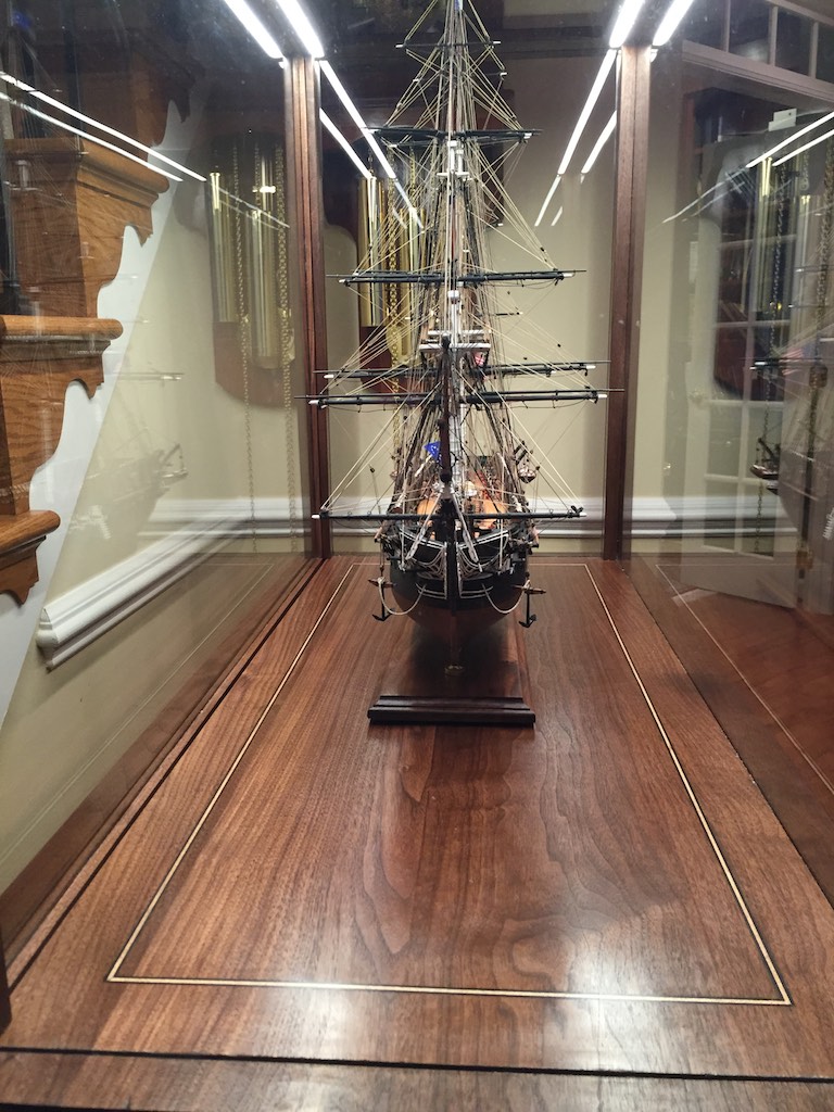
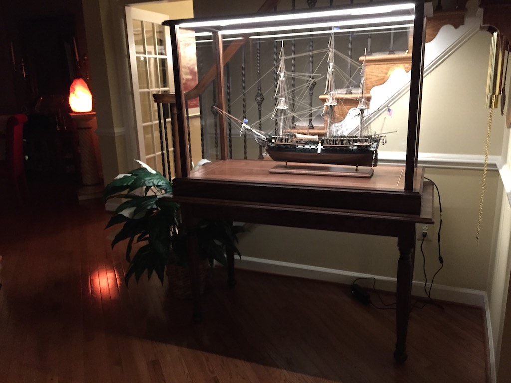
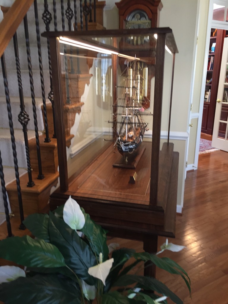
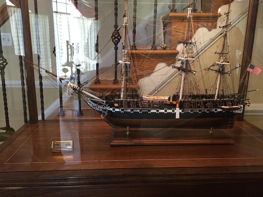
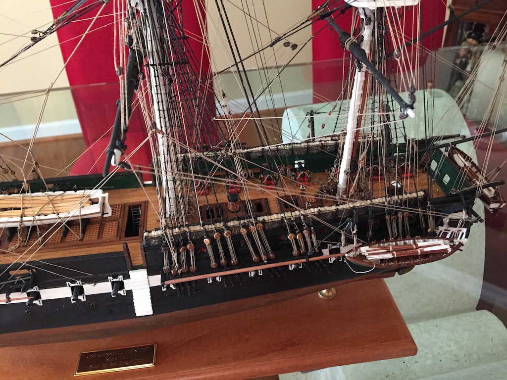
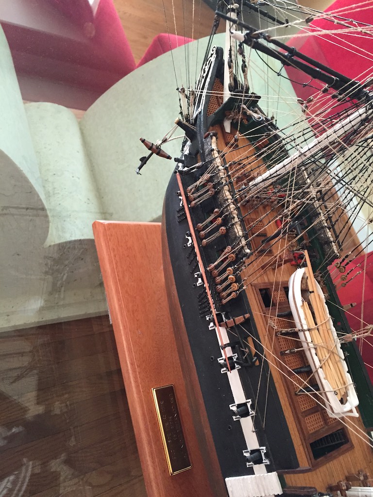
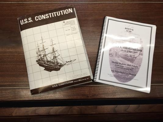
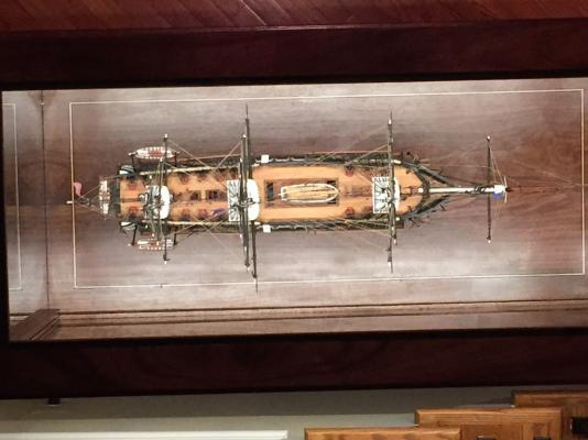
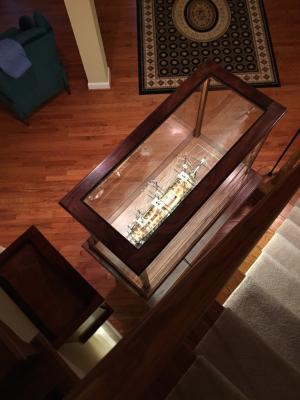
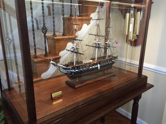
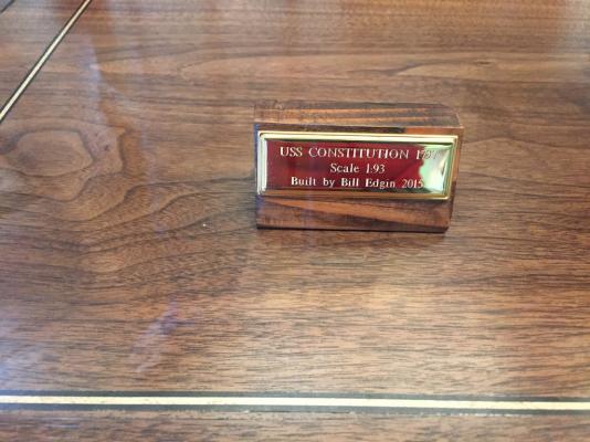
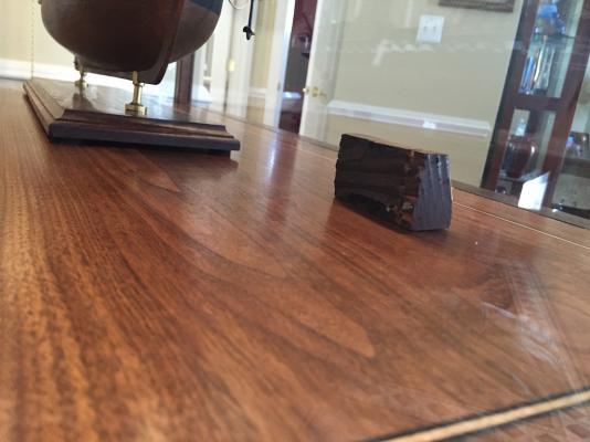
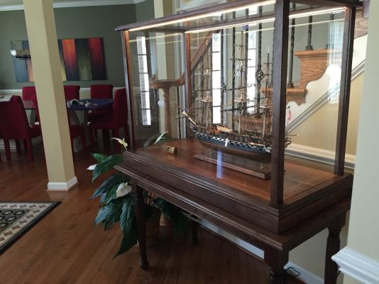
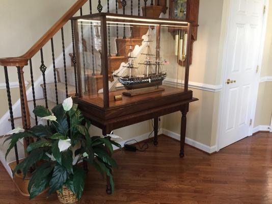
This will be the last posting for the build log. I was able to get the ship installed into the display case. The Connie is now in her berth. I cut the pedestal out of the spar material. I chose to leave the back side rough. It still shows the wear as well as paint from when it was part of a spar on the mighty ship. I spent quite a bit of time researching LED lighting. The top of the case was only ⅞" thick and most of it is glass. I wanted LED lighting that would accurately produce the colors of the ship and be bright enough to allow everything to be seen well. The high CRI led's from Flexfire worked perfectly. They also do not produce much heat which is important in the contained environment of the display. I had a number of goals when designing the case. I wanted black walnut to match that in the ship. I wanted to minimize the size of the surrounding frame to maximize the view of the ship. I wanted a glass top, and wanted the case lit. By utilizing ¼" tempered glass, I was able to use the strength of the glass to augment the rigidity of the frame. The glass is glued in with a GE Silicone household glue. This provides the holding power required and the give needed to allow for any seasonal movement. I also used low iron glass which is the most optically pure on the market. The display case bottom contains a hidden compartment that is large enough to hold the full set of original plans, printouts of the CAD drawings I used for the ship's boats, and a full bound copy of the build log. It has been a fun and rewarding build. Now on to my next ship, a scratch build POF of the Brig Eagle. Thank you all for all of the encouragement, technical and mental support during this build.


- 335 replies
-
- 22
-
-
- Constitution
- Mamoli
- (and 3 more)
-
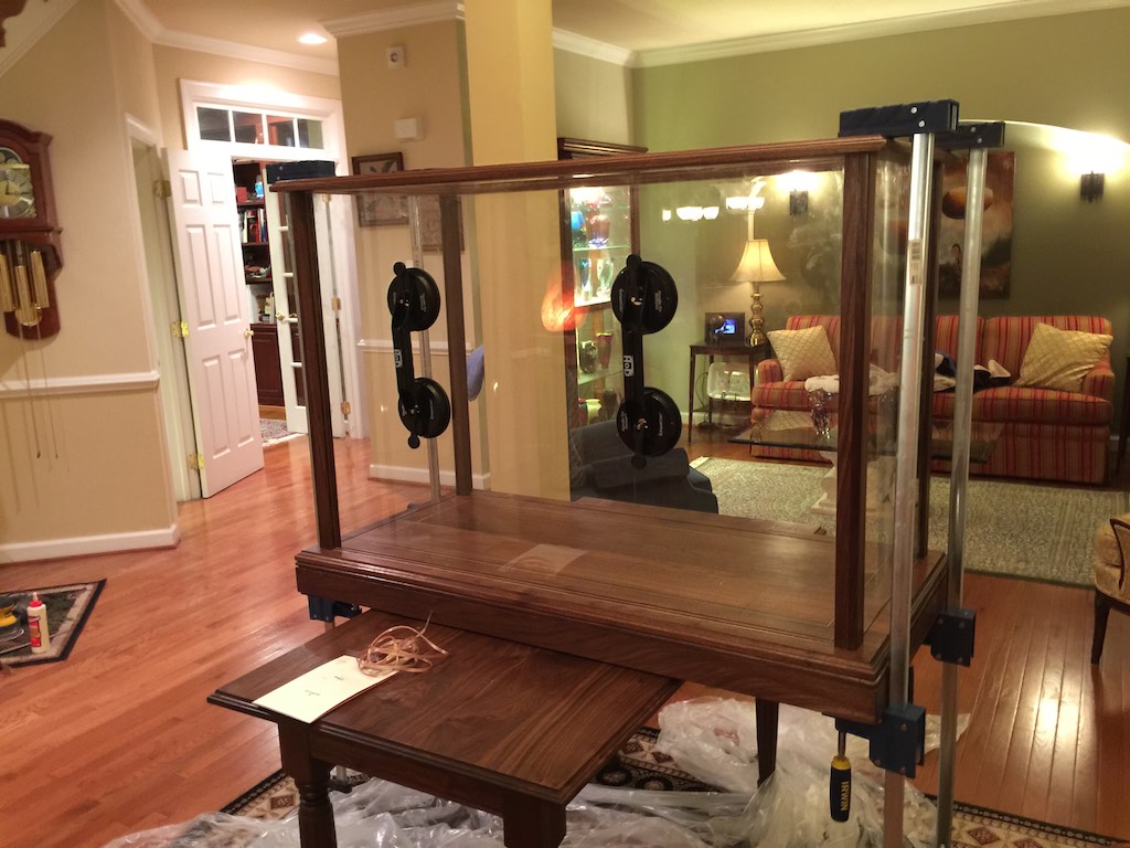
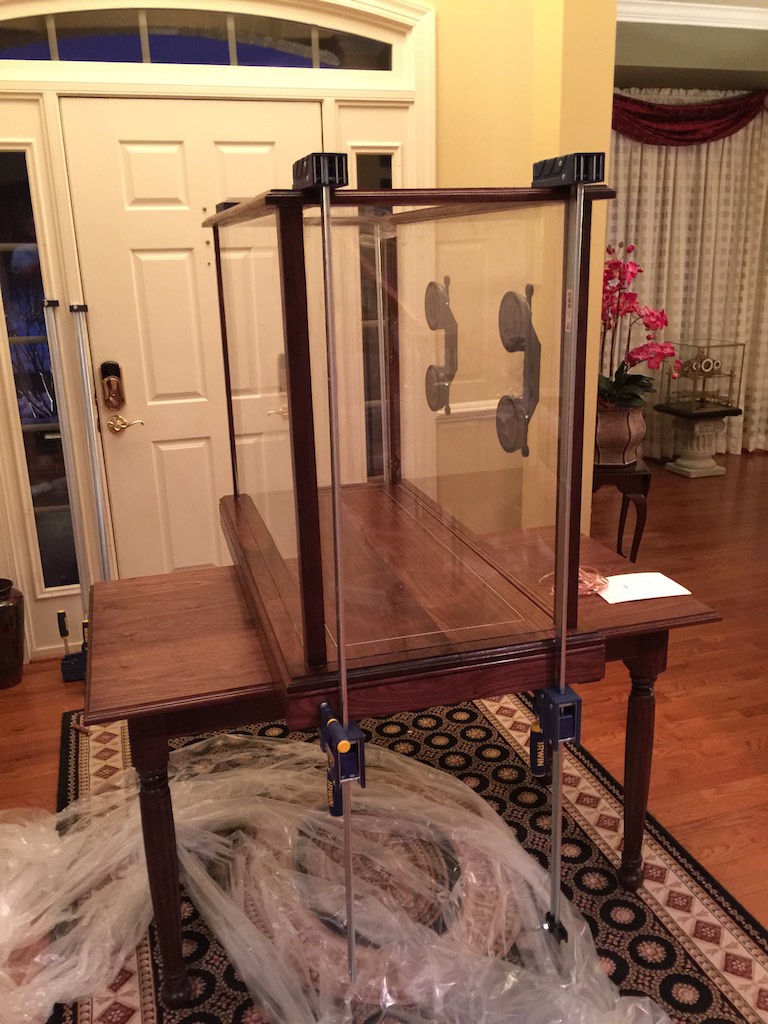
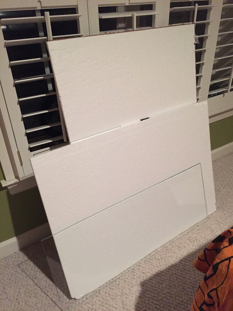
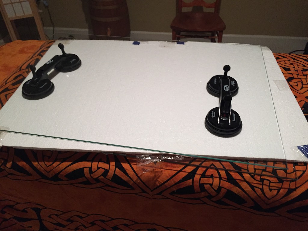
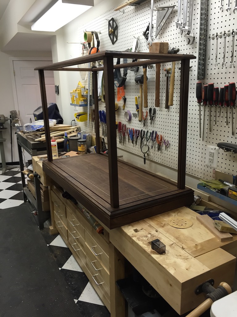
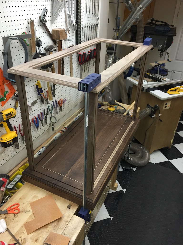
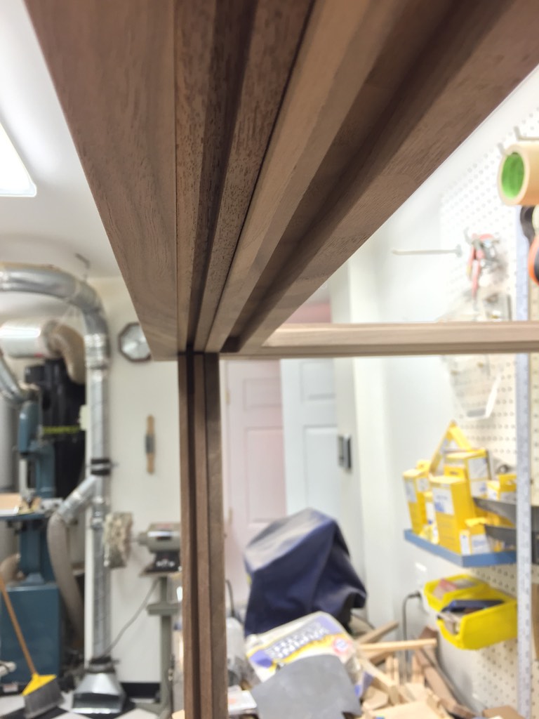
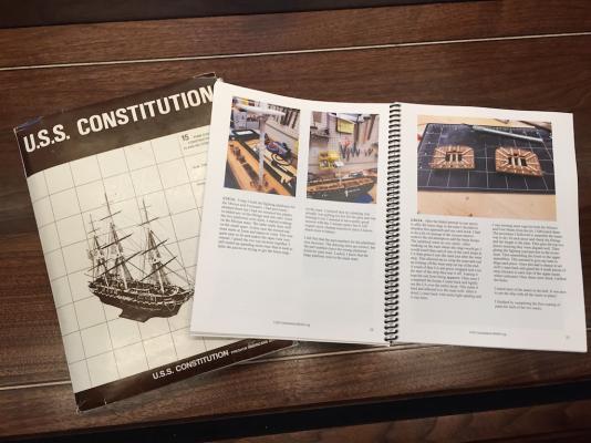
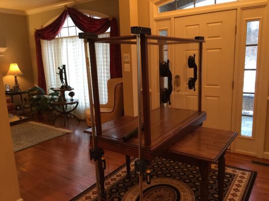
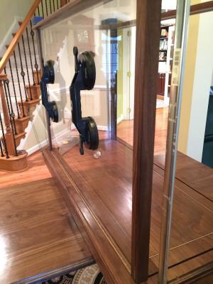
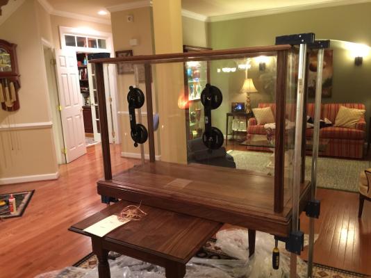
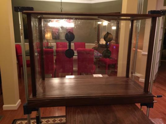
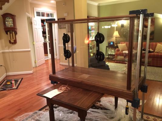
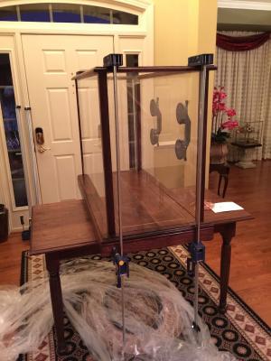
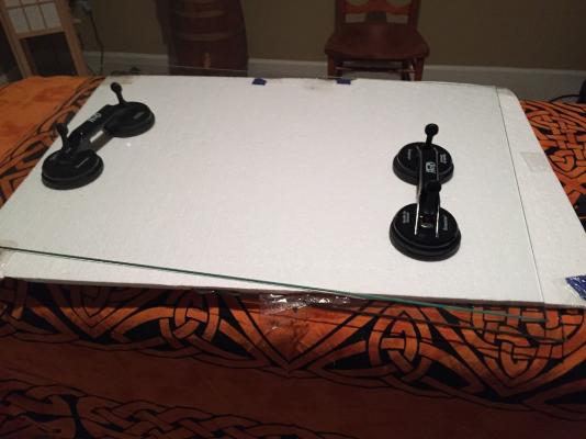
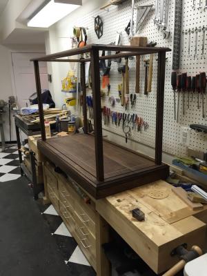
Big step in the case construction today. I have completed all I can do with the case in the shop. Today, I staged everything up in the foyer where it will be located. We moved the table into the center of the foyer to give us a work place. Then we put the case together without the glass so I could fit the access door to her. The largest thing this entailed was running the light wires down through the corner post and into the base. I knew the door would require some final shaping to allow it to clear the sides of the slot as it was slid in place. After a bit of sanding we got the door installed. It fits like a glove. I have to admit, we did put the ship in the case (without any of the glass and turned the lights on. They will work well with her. Here are photos of the door in the case. Then we removed the door and all the clamps and started installing the glass. We started with the side the wire ran through since the top and corner could not be moved apart much without stressing the wire. I put wood glue on the corner top and bottom, then ran a bead of the GE silicone adhesive completely around the glass channel. Once cured this will also provide a great deal of rigidity to the case. Once that was in place we worked our way around next with the front glass then the remaining side. Once these were in place, I applied clamps on each corner and checked for square. Once I was satisfied, I replaced the back access door. Here are photos with all the side glass in place. The black handles are suction cups used to move and handle the glass. These will also be necessary should I need to remove the access door to get to the model. Otherwise there is nothing to hold on to and the frame is inset into the case. Tomorrow I will remove the clamps and clean up the glass and any glue squeeze out. I will also solder the connections between the LED dimmer control and put it all in shrink tubing to dress it. Then we will move the case into position and place the top glass in the top. This just lays in the top on felt. This will allow outgassing slowly since air can filter through the felt around the glass and out. The door will allow some air exchange but not much. I also will touch up the finish where necessary, primarily around the top of the door where I had to fit it. The good news is all of these areas are actually hidden in the joints so not much touch up will need to be done. Tomorrow we will also pick up the printed build log. It follows this log pretty closely but is more extensive and detailed. It also contains more photos of the build. Rob (my Admiral) was kind enough to clean it up and send it off for printing and binding. I have two printed copies. One for our library, and one to be placed with the plans in the hidden shelf under the case's base. The log in the library also notes the plans are in the case. I still need to cut the pedestal for the name plate. This will be cut from the real Connie's spar material (thanks again Popeye2sea). I have waited on the final design of this because I want to see what I need once the ship is installed in the case. That will inform me on the final design of the pedestal. The plate is already made. So barring unforeseen complications, the ship will probably be in her new berth tomorrow evening! I will post a final entry here with some photos of her in place and close this build log.
- 335 replies
-
- 9
-
-
- Constitution
- Mamoli
- (and 3 more)
-
I took the simple approach and just tied it to the shroud where I wanted it to be. Then I touched it with a bit of glue to hold it there. It will need to be in board of where you want it to be since it will move out board once the line goes through it. You will have to play with the length of it. The longer it is, thehigher in the shrouds it has to hang.
- 1,756 replies
-
- 3
-
-
- constitution
- constructo
- (and 1 more)
-
You could deduce where the major bulkheads would be by looking at the cabin and public space layouts. However if you are looking for details of the crew spaces below the public spaces as well as the centralized corridors for crew only spaces, engine rooms, or bridge, these are generally not shown. However, usually the bridge is pretty easy to deduce looking at the ships profile.
-
If you go on YouTube and search for Building Cruise Ship Model you will see amny different examples from Legos to plastic to wood. Here is one that I found particularly interesting from England.
-
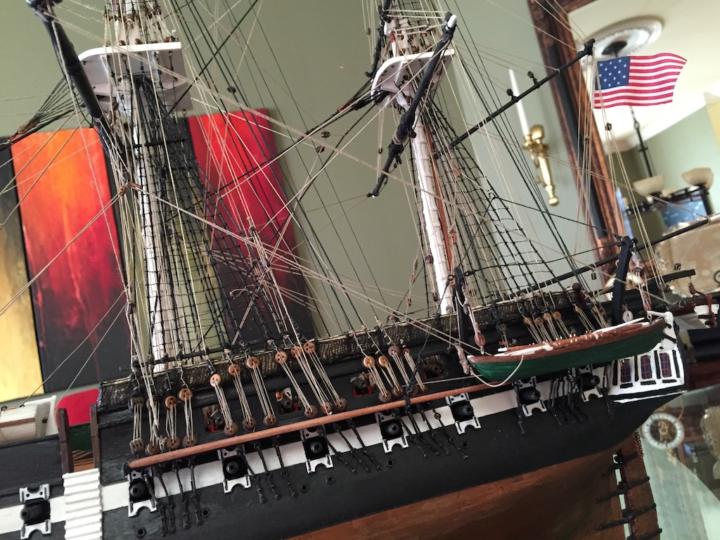
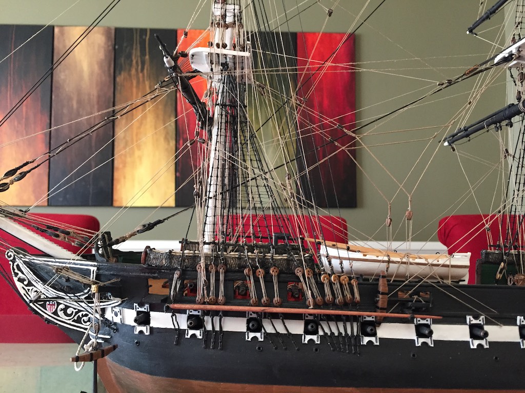
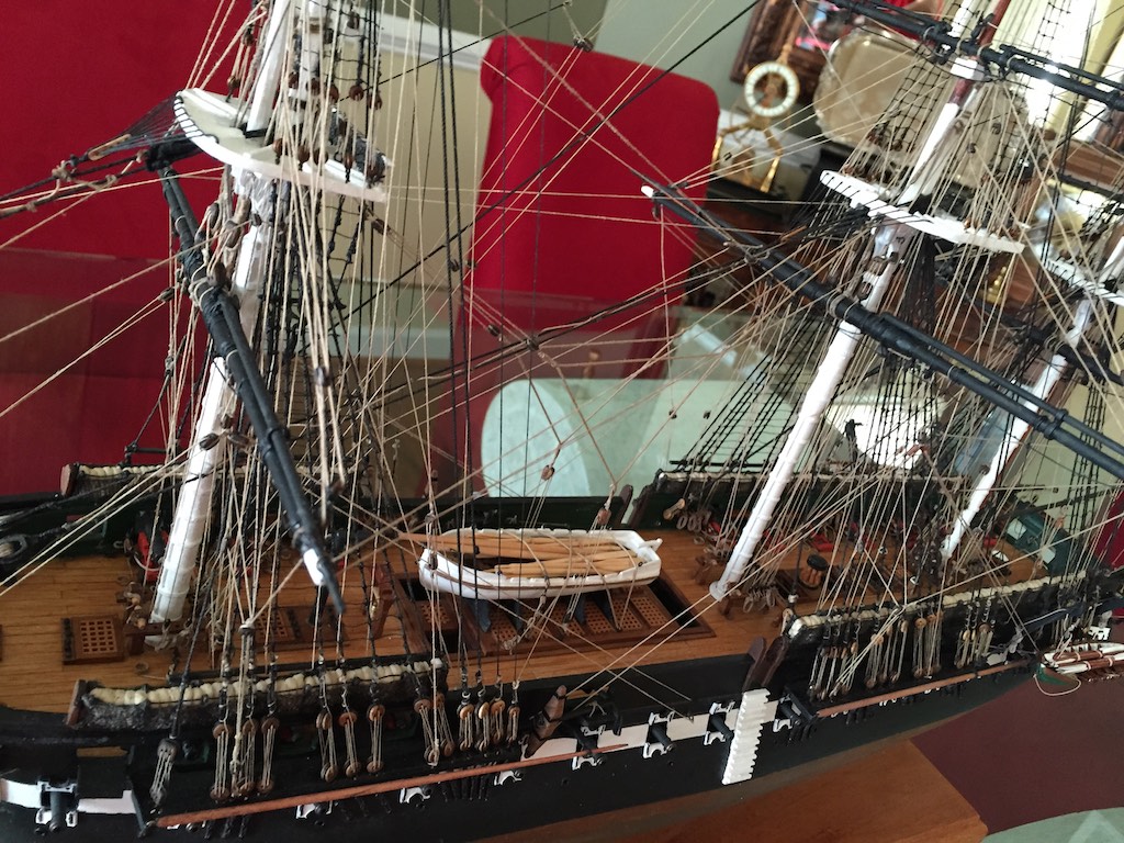
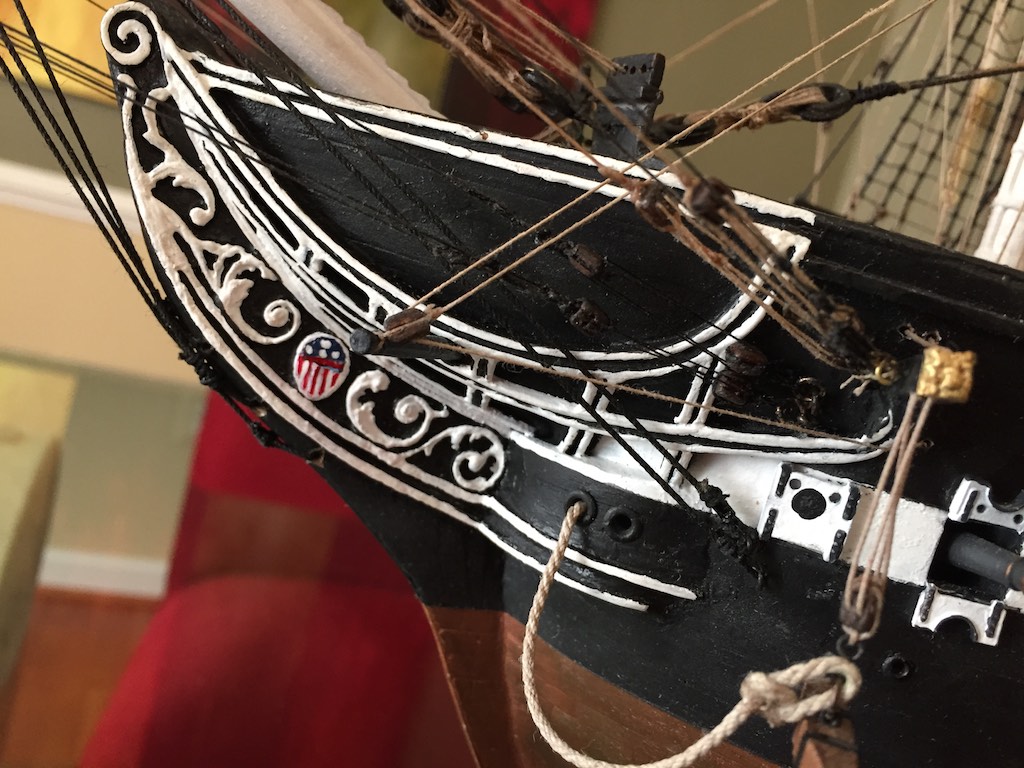
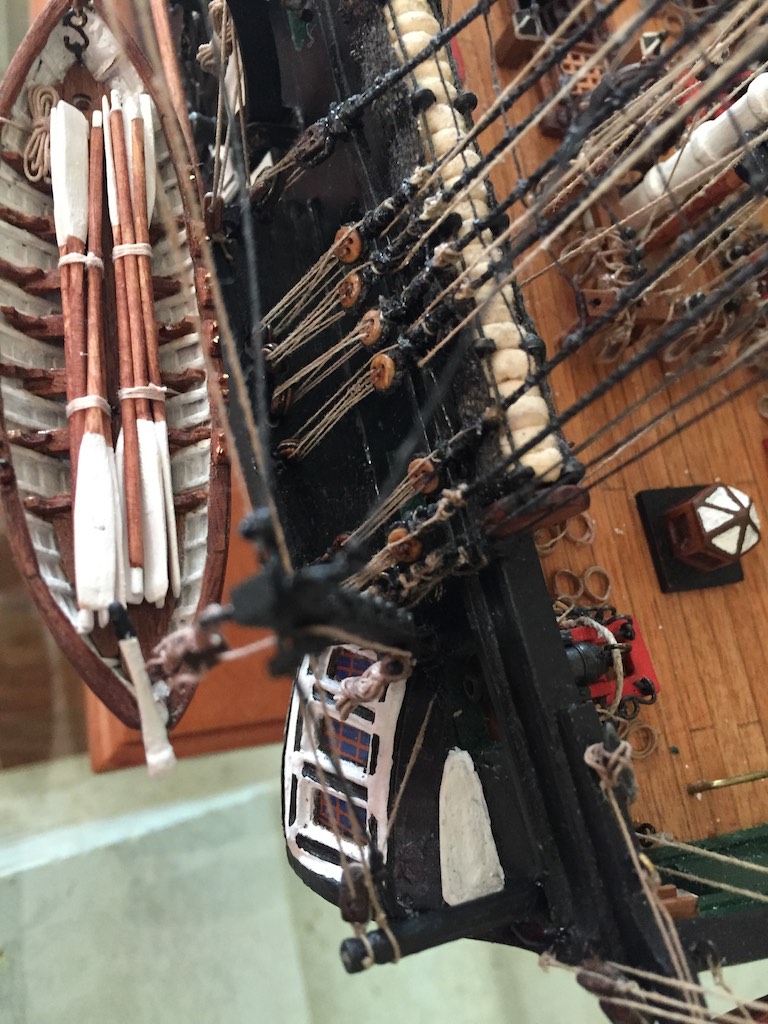
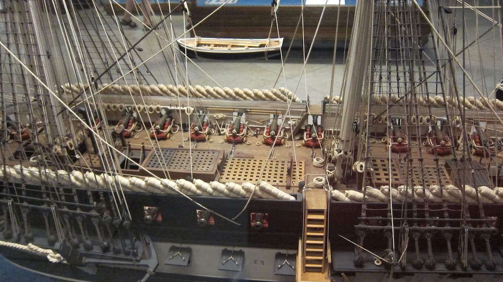
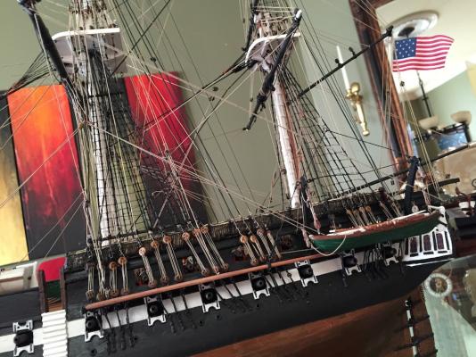
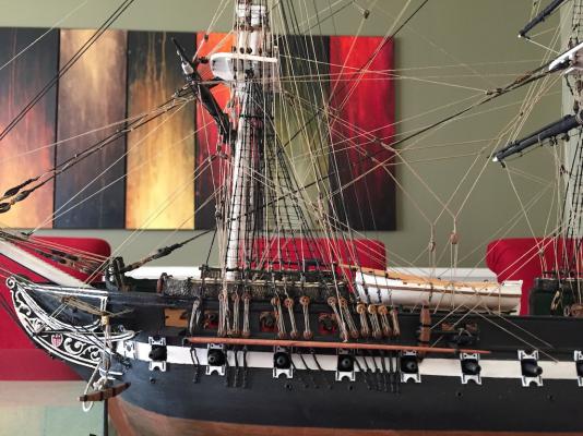
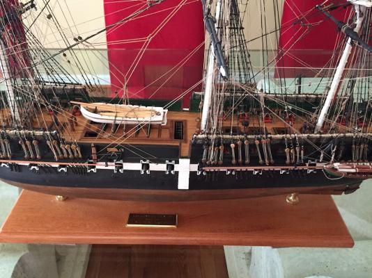
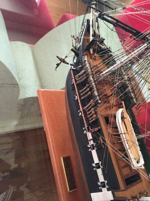
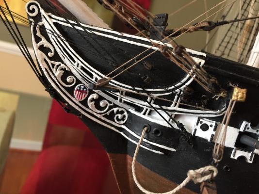
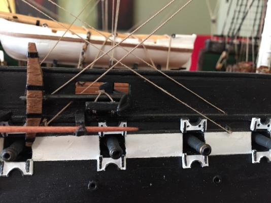
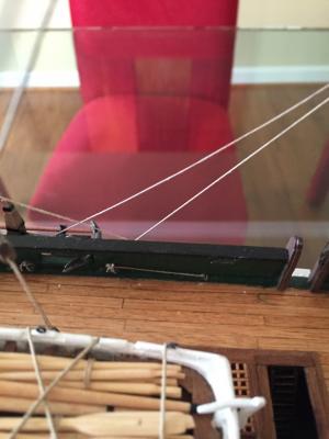
I am not George or Augie, but I can show you the Mamoli rigging. The lower braces on the fore were led back to the main mast then down to the deck. The Tack and Clue were fed through the sides of the ship (holes represent sheaves on my scale). The lower main brace went back to the stern Bumpkins. Also notice on the Clue and Tack rigging, to clear the line over the netting and other obstructions, the line is run through a block strung from the shrouds. This is adjusted until the line runs clear. Below you can see the Main clue and tack running to the sides of the ship. The Brace you can see running to the bumpkin, From there it goes through the side of the ship and to the aft belaying pin rack. Here is the Main Brace going into the ship after the bumpkin. Here you can see the lower Fore Clue and Tack running to the forward bumpkins and aft through the side of the ship. Notice here that the lines start in a ring on the side then return to the same point, but slightly above before entering the ship at the deck level then to a Cleat. Forward Midships Herre is a close up on rigging a snatch block to pull the line over to clear the side of the ship before running it down to the deck. In this you can pick out the Fore Brace running back to the main mast before going to the deck. There are more examples below. Hopefully this helps.


- 1,756 replies
-
- 9
-
-
- constitution
- constructo
- (and 1 more)
-
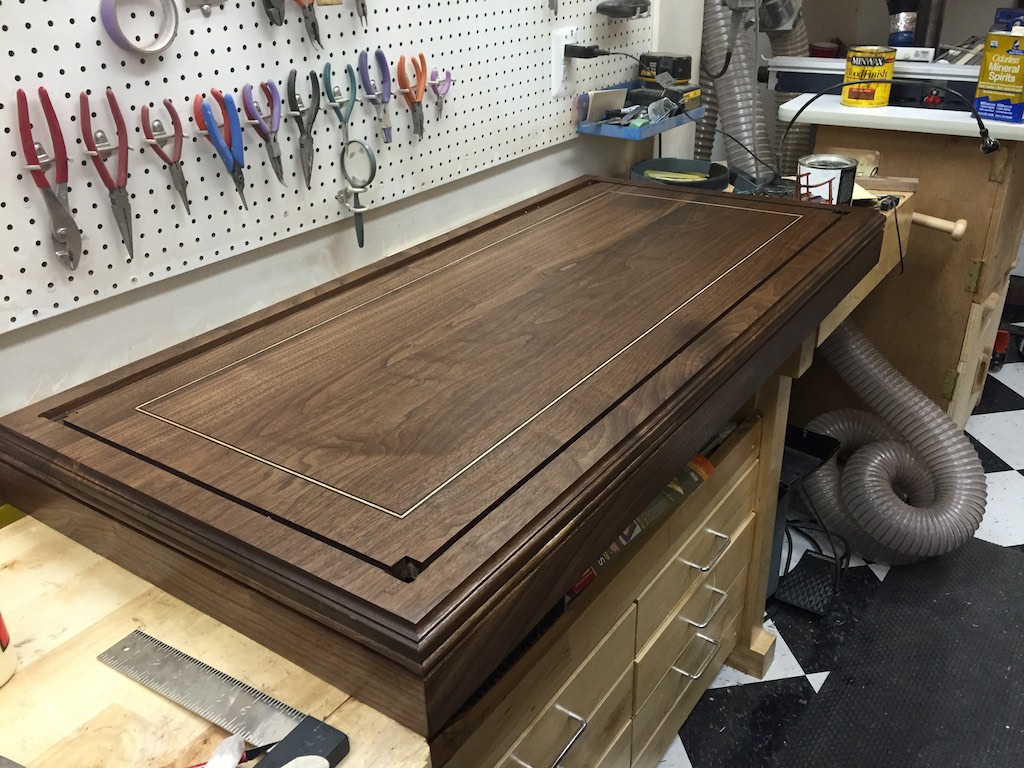
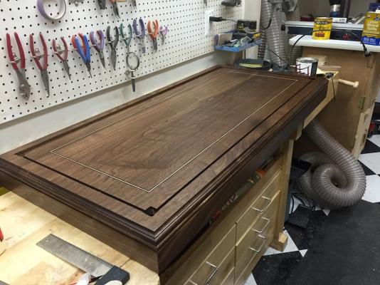
I know I said it would probably be a few days before I updated this again, but I finished the new ship's base today. I still will be adding the poly/oil to it along with the display case. Anyway, since I was updating, I thought I could also show the case after the first two coats of the poly. It really brings out the colors and wood grain. Also, there is a shot of the glass waiting for the case to be finished. I also started working on the LED lights today. I wired the power supply to the controller and tested it.


- 335 replies
-
- 9
-
-
- Constitution
- Mamoli
- (and 3 more)
-
I have to agree with Mark, the ME ropewalk on sale was great to show how to make rope and did make some great rope. However, the quality of the construction would preclude it from making too much rope before it would fall to pieces.
-
It is fun to see a plan come together. It is very satisfying to dream something up, draw it up, and see it become real!
- 732 replies
-
- 2
-
-
- constitution
- model shipways
- (and 1 more)
-
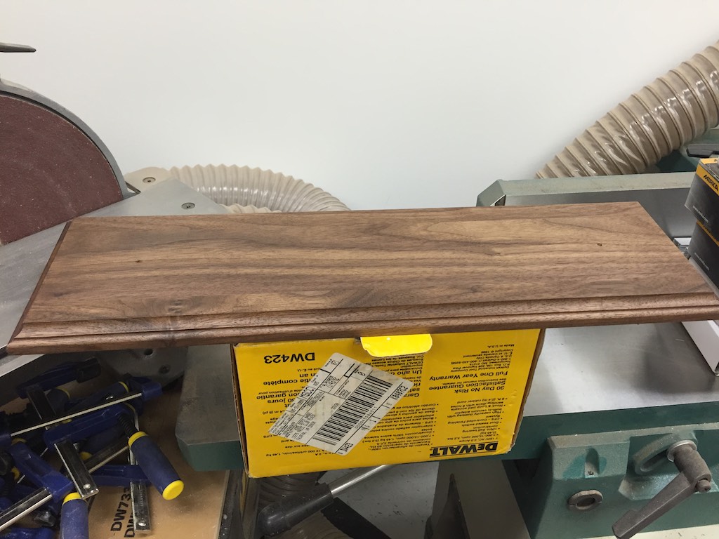
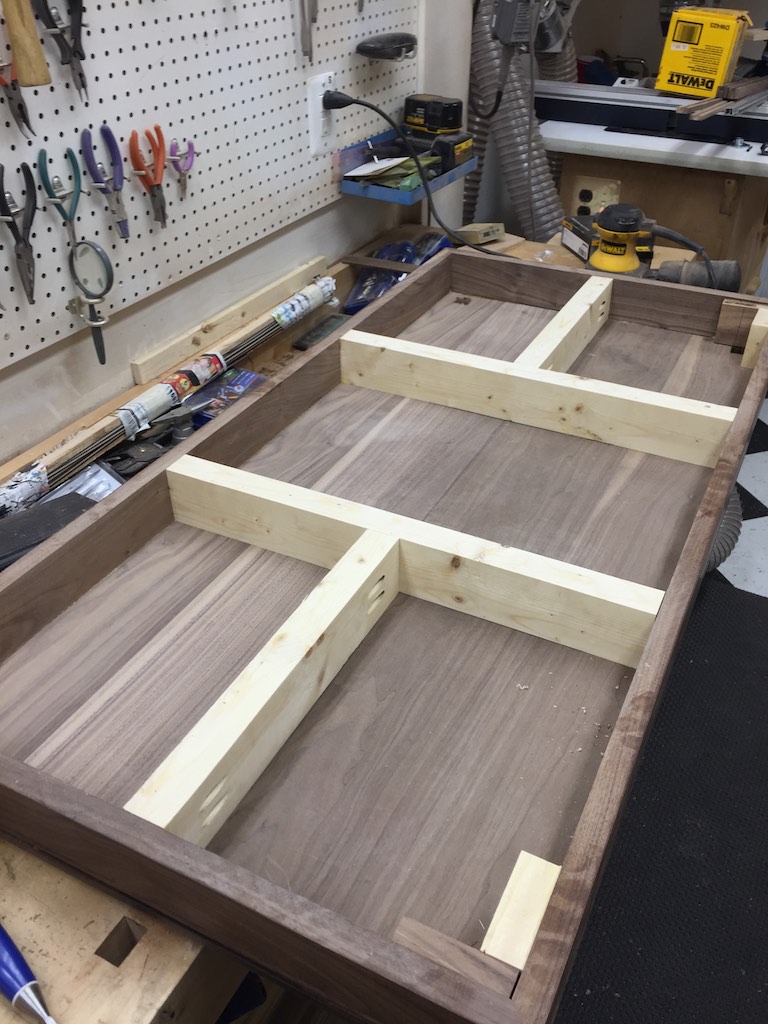
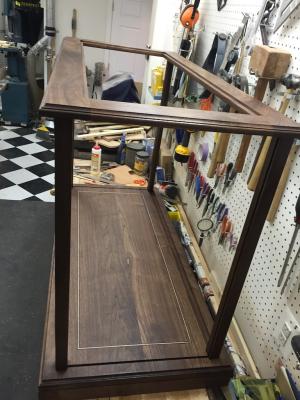
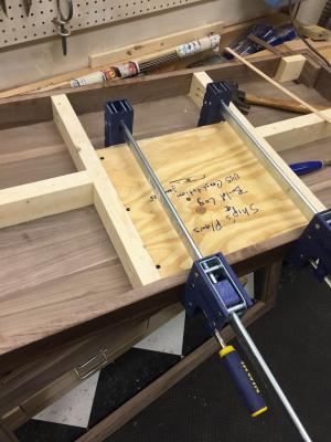
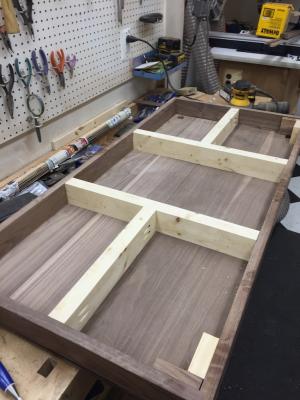
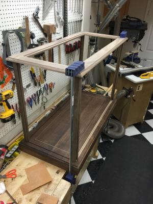
I was able to get the display case construction completed today as well as the sanding and staining. I know there is debate among woodworkers about the efficacy of sanding beyond 220 before finishing, but the Sam Maloof finish called for sanding through 400 and burnishing with steel wool prior to applying the Poly/Oil. Since I had them, I chose to sand through 600 grit using my random orbital sander. I also think it is wood dependent. If this were soft woods, trying to sand beyond 200 would prove useless. However, the walnut seems to do well with it. Then I applied the stain. Tomorrow I will start applying the rub on finish. The photos below show the case dry assembled. I will not glue the case together until all the finish is applied. Then I need to move it out of the workshop and upstairs before I put it together. I think it would be too heavy and cumbersome to move much once the glass is in it. I will do the final assemble a few feet from where it will be set. This shows the construction of the case bottom. The cross supports were primarily to hold the sides in square before the top of the platform was installed. They are white pine so they do not add much weight but a lot of strength to the construction. The plywood being glued here is the hidden shelf that will contain the plans and build log - that way they stay together with the ship. I wrote on the plywood in big letters that it contains the plans and log so it will not be missed. Here is the dry assembled case. You can see how the glass will be inset now. The front of the case is facing outward. I am beginning to see the Connie's new home taking shape. You can also see that the colors are now even. The lighter colored sapwood is no longer evident. You can see the groove for the access door in the back. There is a matching and a bit deeper groove in the top. This will probably be the last post for the case for a week or so. I think ti would be really boring to post pictures of paint drying! I also have to create the new walnut base for the ship. Once I get that done and the ship mounted on it, I will post that. I will also post the assembly of the LED lighting. Since it is custom it will require a bit of soldering and fitting.

- 335 replies
-
- 10
-
-
- Constitution
- Mamoli
- (and 3 more)
-
You should have it in your mailbox. Enjoy.
-
It should scale fine. I used ¼ tempered glass but it could also be easily converted to plastic. I can send you the PDF or an exportable version of CAD if you use a CAD program.
- 335 replies
-
- 1
-
-
- Constitution
- Mamoli
- (and 3 more)
-
I don't mind at all. You will need to adjust the lengths to fit your scale. My Connie is 39 long x 28 tall x 14 wide. The interior dimension for the case is 43 x 30 x 18. If you would like the plans I drew up I will be happy to send them to you.
- 335 replies
-
- 2
-
-
- Constitution
- Mamoli
- (and 3 more)
-
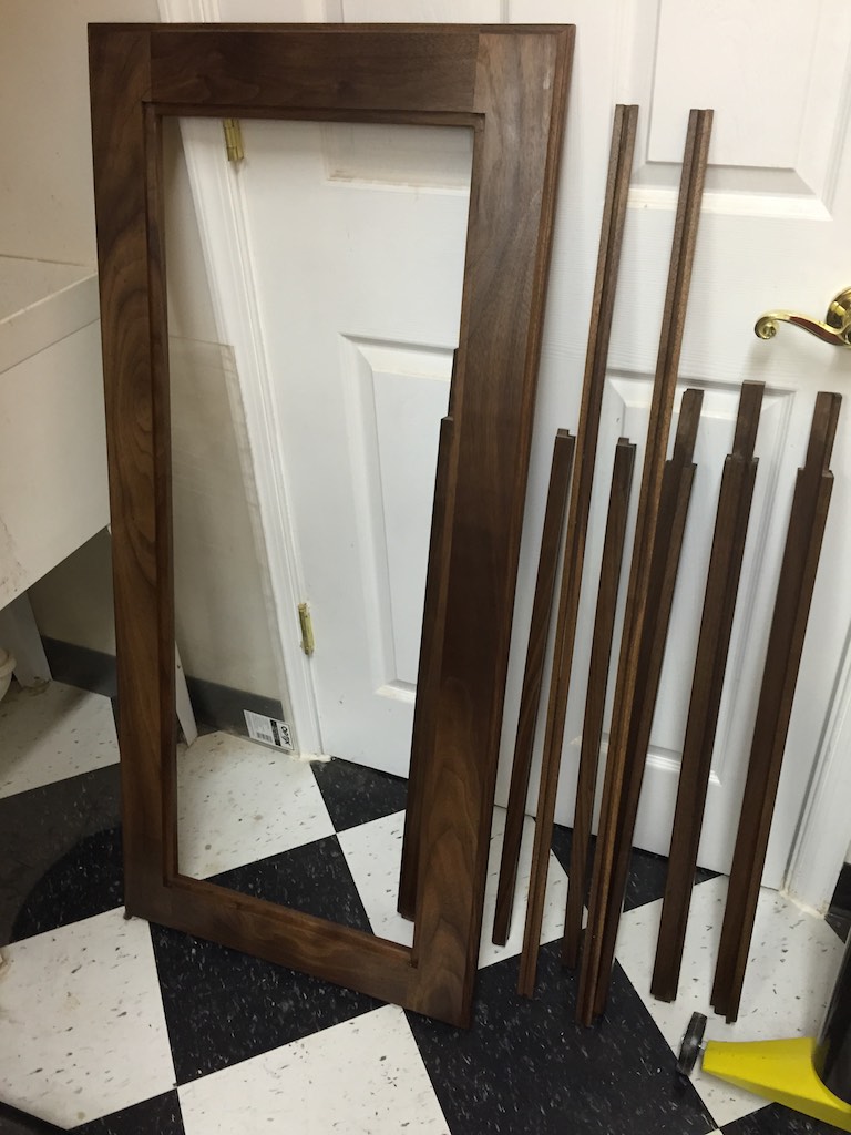
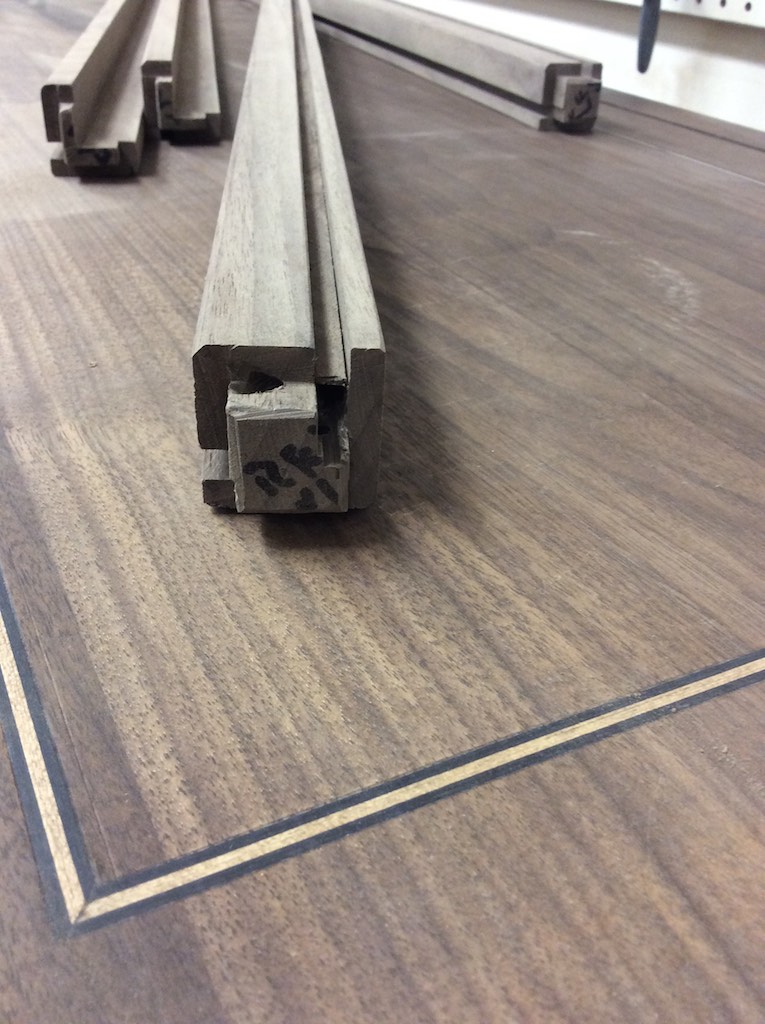
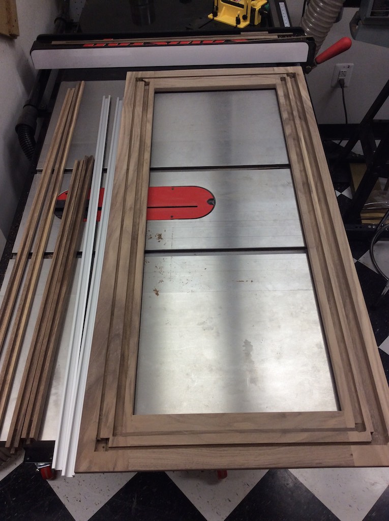
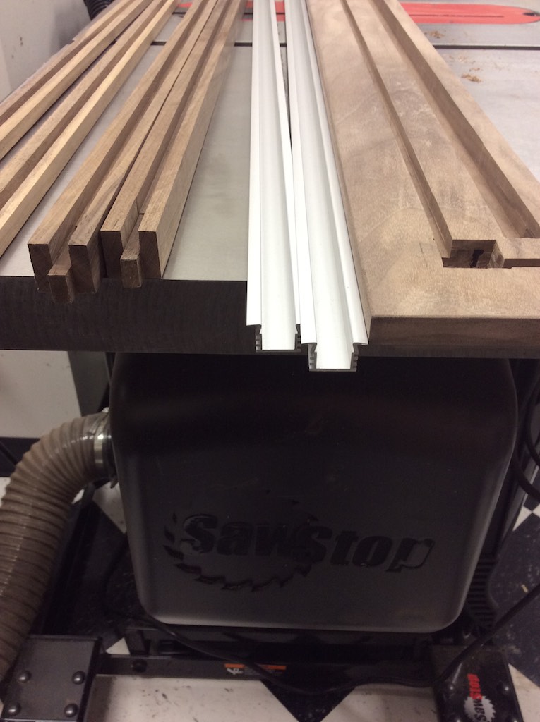
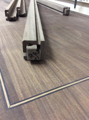
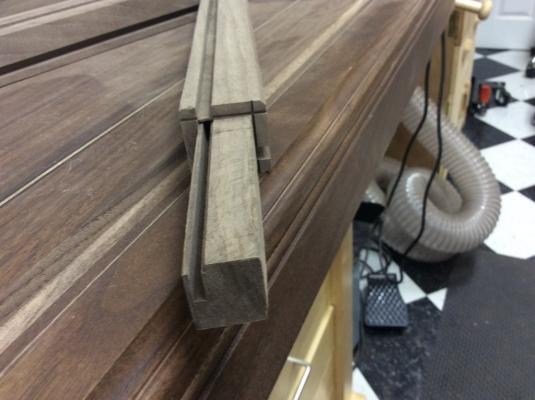
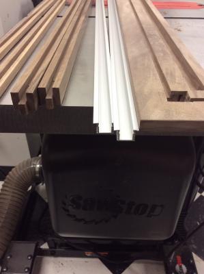
Here it is broken down. Below is the top and access door frame. The door frame pieces are the 4 to the left. The aluminum channels will be for the lights. You can see the routings in the top necessary for the glass and all the other fittings. When all this comes together, everything will be flush with the bottom. The small diagonal channel will be to carry the wire from the corner post to the LED channel. It is a bit hard to se here, but there is a small channel to the left. You can see the walnut insert covering it. This runs on the top side on the opposite side of the previous photo. This connects the two LED strips on either side of the top. This provides a nice photo of the LED channels. There is a diffusion cover that snaps in the channels over the LEDs. This shows the top of the corner post showing where the wire exits the post and will enter the diagonal channel shown above. This shows the bottom of the same corner post. The bottom post extends down through the base and is supported by blocks on either side where it will be glued. The wire will be led through the base and out the back to the dimmer control and power supply. Here is the base along with the four corner posts. The light color in the channel to the right will be darkened by the stain. This will be the drop in channel for the back access door.


- 335 replies
-
- 8
-
-
- Constitution
- Mamoli
- (and 3 more)
-
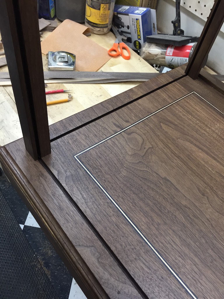
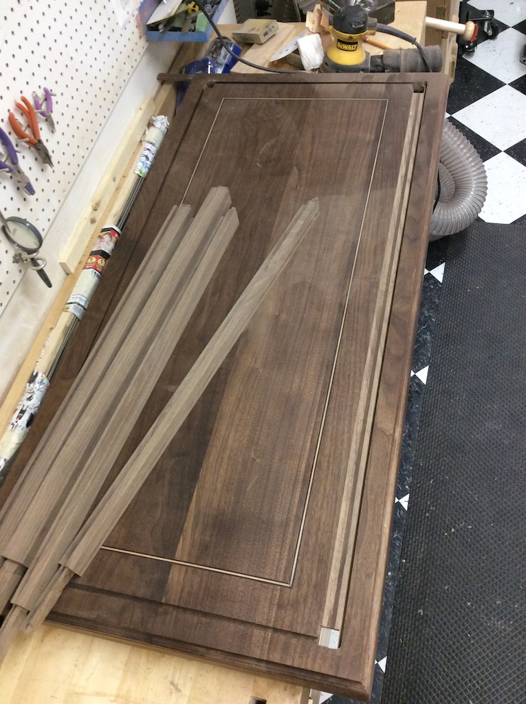
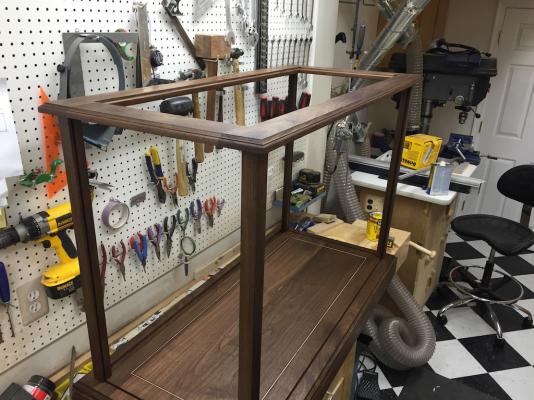
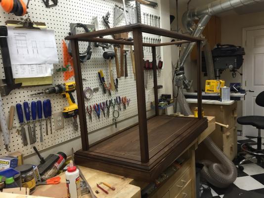
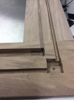
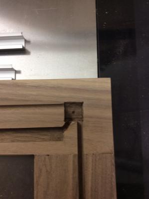
It has been awhile since I updated the display case. I thought today would be a good point. Since the last update I have been cutting, shaping and joining the various pieces that make up the case itself. Since the glass, LED lighting, and access door are all inset into the frame and base the joinery has been fairly complicated (at least for me) so I have taken my time in measuring and remeasuring before I cut anything. I really do not want to have to run out to Manassas and get anymore Walnut because I screwed up a measurement. So everything is now cut out, shaped, and joined. Trust me, I have made a LOT of sawdust! I also spent time cutting the channels to run all the lights and electrical cords through. They will run up from inside the base through one of the corners into the top. There will be aluminum channels with the LED lights mounted in them inset flush to the top. The next step is to continue sanding on all the pieces then once I get beyond 220, to stain everything. I also still need to add some support blocks within the base so I can glue the corners into it. I assembled everything minus the glass and lights today for the final check before I started sanding and staining. Once everything is sanded and stained, I can apply the Poly/Oil finish. This shows the underside of the top. You can see the top of the access door frame as well as the channel for the LED lights. The access door will be lifted into the upper slot, then lowered into a slot on the base. Once it is installed it will be flush with the rest of the case frame. Incidentally, you can also see the color variations within the walnut. This is one of the reasons a stain is good to treat the walnut and even out the color. The other being walnut tends to yellow as it ages so the stain keeps the color consistent as it grows old.

- 335 replies
-
- 4
-
-
- Constitution
- Mamoli
- (and 3 more)
-
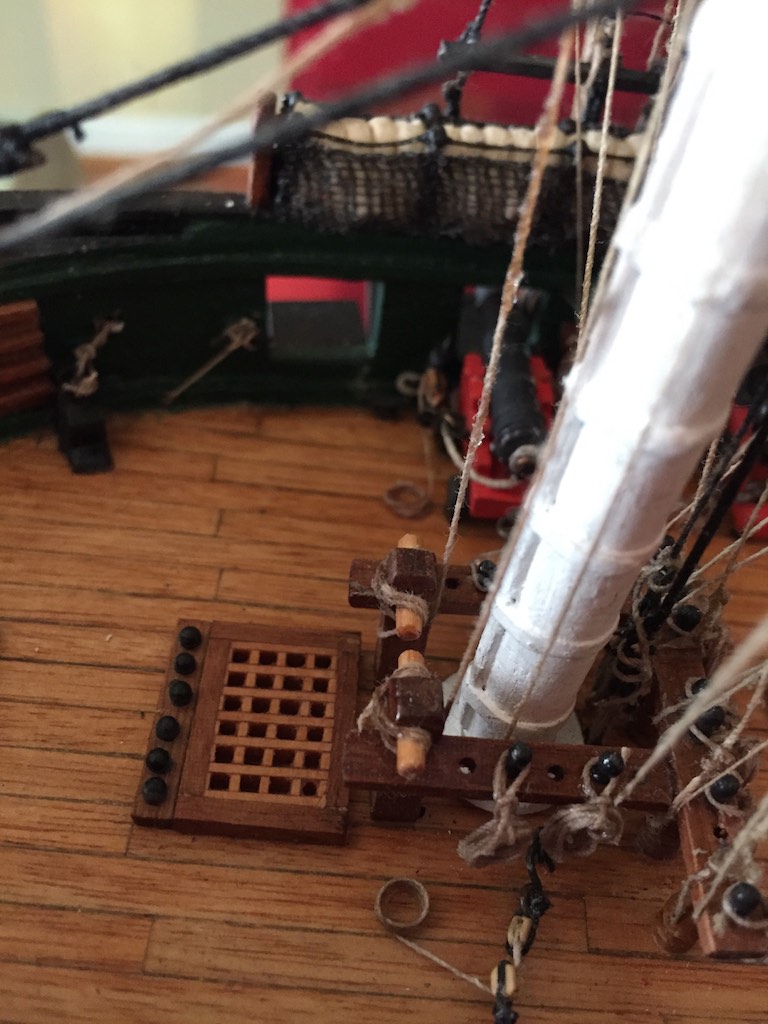
Certainly every belaying hole has it's use. Since I did not rig sails, I did not have all mine populated. Which is a good thing because I used almost all of the metal belaying pins Mamoli put in the kit. However, I would think even with the sails up there would be open points. given the ability to change points based on the wind. It does raise a bit of a question. A sail's sheets would be rigged to both sides but only one would be tight depending on the wind direction. I suppose the other line would be terminated still, just loose I guess.
- 1,756 replies
-
- 2
-
-
- constitution
- constructo
- (and 1 more)
-
I used metal stools for a long time in the shop. What I found was they did not hold up well to me moving around, swiveling between tools etc. FInally I broke down and bought a chair from Safeco (on Amazon). It was certainly more expensive than stools, but it rolls, has a back, cushioned, and is made of a high quality rubberized material that wipes off well so dust is no issue. It comes with an optional back which I also really like. Heavy very well made chair. I have had it a month or so now and really like it. Much more comfortable than the previous stools I had in there.
-
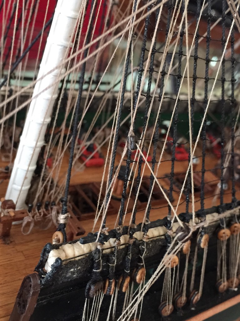
I used a hammock size of 6' x 4'. At the 1:93 scale that equated to 19mm x 13mm. Since I was putting them on end in the cranes, the main dimension I needed was the 13mm. The other dimension would just result in a skinnier or fatter roll. I took the cloth I was going to use and tested rolling them up until I was satisfied with the results. You could do the same as a test to see how large you need to make the demarcation marks. I too was a bit concerned that there needed to be enough hammocks to look correct. At the high point there were nearly 500 people on board. However, the officers would not have used the standard hammocks. It is possible the marines also might not have. However, I do not think anyone is going to stand next to the ship and count how many hammocks I rolled up.
- 732 replies
-
- 3
-
-
- constitution
- model shipways
- (and 1 more)
-
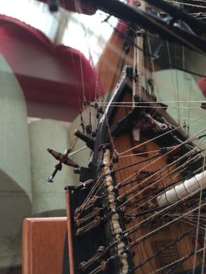
Jay, When I was going through the Maritime Museum in Lisbon a few months ago I got photos of many of their models with the hammocks slanted. Here is an example of what their model hammocks looked like. Unlike the Connie, most of their models had troughs along the top of the rail to put the hammocks in.

- 732 replies
-
- 5
-
-
- constitution
- model shipways
- (and 1 more)