


TBlack
-
Posts
1,305 -
Joined
-
Last visited
Content Type
Profiles
Forums
Gallery
Events
Everything posted by TBlack
-
 Rob, So, as I understand it, you're trying to figure out how to make the metal fittings that fairlead the chains, and to quote you: " Creating something from total scratch or modifying something from some totally different other thing is a testament to a strong mental prowess….. a fruitful imagination and ingenuity. " I guess you've got it all! Thanks for the journey. Tom
- 3,560 replies
-
- 1
-

-
- clipper
- hull model
- (and 2 more)
-
Bummer! But I've often felt that our real creativity is not in the building of the model, but in correcting our mistakes. Tom
- 505 replies
-
- 9
-
-
- vanguard models
- Sphinx
- (and 1 more)
-
Ron, I'm trying to imagine the actual operation of all that threading and twisting, which turned out marvelously, was there any swearing that accompanied that operation?
- 542 replies
-
- 1
-

-
- Sphinx
- Vanguard Models
- (and 3 more)
-
Jason, You are not bound to the screws that came with the pedestals. I don't know their size, but perhaps a thinner screw would save the day? Alternatively, if you epoxy the pedestal in place and then insert the screw, wouldn't that work ok? You've done such a terrific job so far on this model that I can't stand the fact that mere pedestals are creating a hurdle. Tom
-
Mark, A lot of PE parts to install, and all looks good. With the 2 PE parts on the upper counter there isn't any room for a name. Doesn't look like you're in over your head. Tom
- 505 replies
-
- 6
-
-
- vanguard models
- Sphinx
- (and 1 more)
-
NRG VIRTUAL WORKSHOP - USING THE TABLE SAW
TBlack replied to kurtvd19's topic in NAUTICAL RESEARCH GUILD - News & Information
Nice video, Kurt. Allan and I share one of those fingers. Also, nice to hear your voice after all these years. Tom -
NEW MEMBER and new to model ship building
TBlack replied to Peter6172's topic in New member Introductions
Welcome, Peter! Your daughter being in HMAS ships, you and she must be Australian? Also I find it interesting that she served in the Adelaide, one of whose missions is anti-submarine. And then she served in a submarine one of whose missions is anti-frigate. So, she managed both sides of that equation. You must be very proud! Tom -
Bill, The storm has hit here, too, which has given me time to work on my build. My build also requires copper plating which I have never done before, so I'll watch your progress for instruction/inspiration. Tom
- 89 replies
-
- 3
-
-
- bluejacket shipcrafters
- revenue cutter
- (and 1 more)
-
Rob, I'm sure a good idea, but I'm lost on your reference to office folder tabs. Illustrate? Tom
- 3,560 replies
-
- 1
-
-
- clipper
- hull model
- (and 2 more)
-
Everybody seems focused on your placing of the mouldings and name (I agree, totally), but you skipped over the paint job on the transom decorations, some of which are quite small. Yet another display of your talents! Tom
- 857 replies
-
- 3
-
-

-
- Sphinx
- Vanguard Models
- (and 1 more)
-
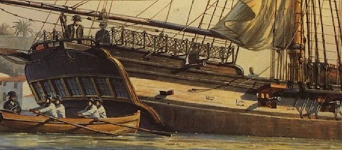
Just as a refresher, here's the picture that is my guide: Note that there is very little tumblehome aft (maybe the wale tucks in a little at the aft end) . I'm using that fact to guide me in forming the last 3 bulkheads which need bulking out. I take it a little bit at a time, so I'm going to be slow. And thanks to all for the likes, checking in, and following. I'll try not to disappoint. And maybe even be a little entertaining. Tom
- 341 replies
-
- 6
-
-
- Sophie
- Vanguard Models
- (and 1 more)
-
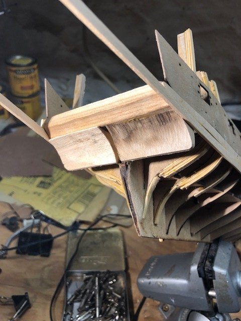
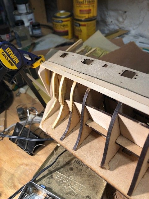
I've been absent from here, but not the workshop. I'm apparently really slow in envisioning how the hull line are going to work towards the stern. I've finally made some decisions that seem to be working out. Here's a start. Originally I thought the lower counter was convex, but that doesn't leave room for rudder movement. Must be concave: Getting to this place enables me to start to adding planking to the hull which, ultimately, helps to form the bulkheads for a smooth finish. This is going to take a while!
- 341 replies
-
- 10
-
-
- Sophie
- Vanguard Models
- (and 1 more)
-
Your ability with the scroll saw is most remarkable. Those bulkheads are works of art in themselves. Tom
-
Nice recovery! Looks good. TB
-
I'll second what B.E. and Druxey have written. It also looks like you've got an excellent set of plans to work from. Tom
- 542 replies
-
- 1
-
-
- Sphinx
- Vanguard Models
- (and 3 more)
-
Dodgeyhack is right, that is a useful tool for the bench. But I suspect the real key is keeping the blade very sharp. Maybe Hollowneck will share with us his technique? Tom
- 542 replies
-
- 1
-
-
- Sphinx
- Vanguard Models
- (and 3 more)
-
USS Delaware 1817 by threebs
TBlack replied to threebs's topic in - Build logs for subjects built 1801 - 1850
That's not a garage; it's a museum! Tom -
Steve, Thanks for this, but I think I'll go with the 7 window option and have the outer two windows be fake, like Fair American. And Sophie is described as being very low in the water. Also, Sophie has royals and stun'sls. Gregory, You can see on my plan where the stern post is. Just aft of it would be the rudder post which, let's imagine, that it stops just below the deck of the captain's cabin and the tiller attaches there. Tom
- 341 replies
-
- 3
-
-
- Sophie
- Vanguard Models
- (and 1 more)
-
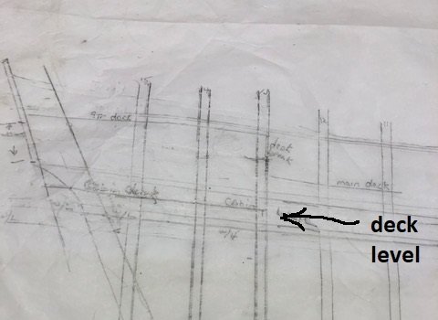
Gregory, Thanks for your observation, but that's not the plan to use. This is: Back in my posts #13 & 14 I show how I got to the above plan. The arrow points to the deck in the captain's cabin. I haven't entirely figured out the complete stern arrangement yet. I should also point out that what O'Brian describes in the book and what shows in the cover picture don't always match. As an example, Aubrey says he can look through 7 stern windows when sitting in his cabin. That's an impossibility, given the configuration of the Sophie as depicted in the picture on the cover of the book. At the same time, the ship's wheel, according to the book, is clearly on the quarterdeck. So, that's where it's going. Tom
- 341 replies
-
- 2
-
-
- Sophie
- Vanguard Models
- (and 1 more)
-
Gregory, Yes there is plenty of room for the tiller to move. Not a problem there. Furthermore, in other ships with a wheel, regardless of where it was situated, had to deal with the same mechanics and space, right? Vane, delighted to see your response. Yes, you got that description of the project just right. In one sentence you've captured what it has taken me three pages to say! Tom
- 341 replies
-
- 4
-
-
- Sophie
- Vanguard Models
- (and 1 more)
-
Gregory, I’m just. Guessing, but maybe the steering cables went straight down from the drum, through the captain’s cabin, into the space below, and thence to the rudder post? Tom
- 341 replies
-
- 2
-
-
- Sophie
- Vanguard Models
- (and 1 more)
-
Steve, Your quoted passages are on pages 79-80 in my edition. While Mr. Brown thought the yard should be shortened, Jack thought otherwise, and instructed the carpenter, Mr. Lamb, just to touch up the stop-cleats. The spar was never shortened and remained at 43 feet. Tom
- 341 replies
-
- 2
-
-
- Sophie
- Vanguard Models
- (and 1 more)
-
Steve, You're never too granular for this hobby. Keep it up! Sophie was always going to have a wheel. Page 69 of my paperback edition of the book says that Jack took the wheel, and that the wind blew his hat off, getting caught in the hammock netting. So, the wheel is on the quarterdeck. Tom
- 341 replies
-
- 2
-
-
- Sophie
- Vanguard Models
- (and 1 more)