
TBlack
-
Posts
1,311 -
Joined
-
Last visited
Content Type
Profiles
Forums
Gallery
Events
Everything posted by TBlack
-
 Pete, How do I get on your Christmas list? Tom
- 209 replies
-
- 1
-

-
- muscongus bay lobster smack
- midwest products
- (and 1 more)
-
Ron, That plug looks fabulous. A really good piece of work, so it's with some trepidation that I make the following suggestion: if the plug were of the dimensions of inside the frames then you could lay the frames on the plug and not have to cut slots for them. Wouldn't that be easier? Tom PS. I know I just dropped in on your build and have just looked at your artistry with the deck furniture. You clearly know what you're doing. Maybe I ought to just shut up.
-
So, Cap't. Bob, you're off on another adventure! No cobwebs on you! That link was very informative, and the drawings are quite detailed right down to showing the planking on the deck. But I didn't see that they included the step. Not difficult to include if you can figure out where it goes. Finally, 1:48 is going to seem huge after that last effort! Good luck with this, Tom
-
Michael, I'll stick my neck out here (I'm not an aesthetic kind of a guy) and agree with John on the lower coaming given where it's placed. The reason for it is to keep water that washes down the deck from coming into the cockpit, so how high does it need to be? Tom
-
I think that turned out just fine. Are you telling us that RC is out completely, or just for this build? Oh wait! Is there any water in Arizona to float anything? (just kidding) Tom
-
Michael, is that you in the bo'sun chair taking the picture?
-
OK. If Michael, Greg, Bob, John, and Popeye think the cockpit surgery was an improvement, so do I, although now there's no place to sit. Tom
-
Flying Dutchman, I was just in a Rockler store this afternoon and saw that they have 1/8" dowels (and larger) in various hardwoods. Furniture makers use them in their joinery work. You've mentioned Woodcraft, now Rockler, there must be others that cater to home woodworkers. Tom
-
It looks to me like the stern plating has the "oil canning" effect. Very realistic. Did you do that, or does the kit come that way? Tom
-
Michael, Good news and bad news? Too bad the owner of Floss wouldn't respond. I think that's kind of tacky. But good news that you have found an actual boat to model. No speculating! Any possibility that you can travel to see the boat yourself rather than rely on the owner to get just the right picture? Tom
-
Pete, I, too,am in awe of your work. But I'm getting a little confused. In your posting #129 there are 3 lobster smacks in the picture, but I thought the scratch built boat was hull #3 and it looks like it's really boat #4? BTW, if I had to choose, I'd go for the boat with the brightwork hull and white boot topping. I really like the colors. Tom
- 209 replies
-
- 1
-
-
- muscongus bay lobster smack
- midwest products
- (and 1 more)
-
Pete, Nice work, so far. You'll certainly end up being the resident expert on lobster smacks! I didn't quite understand why you needed to strengthen frame #1 and stain/varnish it. Will it be visible? Oh, and does anyone in CDA understand what you're building? Tom
- 153 replies
-
- 1
-
-
- musongus bay
- sloop
- (and 1 more)
-
SS Vinal Haven by TBlack - FINISHED
TBlack replied to TBlack's topic in - Build logs for subjects built 1851 - 1900
Michael, If my brass work passes muster it's because you taught me how. Andy, For the blowdown muffler, I tried your hand drill method which worked much better, much cleaner. John, Cap't Slog, Andrieke, thanks for looking in and your support. I have to put some more braces on Amanda, so my attentions will be redirected for awhile. Tom- 326 replies
-
- 1
-
-
- vinal haven
- steam ship
- (and 1 more)
-
SS Vinal Haven by TBlack - FINISHED
TBlack replied to TBlack's topic in - Build logs for subjects built 1851 - 1900
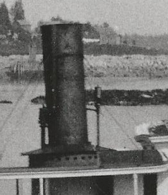
So I added the whistle and "steam blowdown muffler" to my funnel assembly. Except for some cleaning up and painting here it is:
- 326 replies
-
- 7
-
-
- vinal haven
- steam ship
- (and 1 more)
-
That eyebrow looks fabulous! John and I both want to know how'd you pull that off so smoothly? Tom I see I posed my question at the same time you answered. I'll keep quiet next time. But I'm shocked! Shocked! that a sailor would swear!
- 382 replies
-
- 3
-
-
- stadacona
- sylvan scale models
- (and 1 more)
-
Andy, Some time ago I looked at the portholes that you put in your superstructure and marveled at their roundness, figured you just drilled them out. Fast forward to my build of Vinal Haven where I had to put a hole through styrene to acommodate the pipe for the whistle. The heat from the drill melted the plastic such that I ended up with a hole bigger than I intended. Easy enough to fix, but did you do something differently to avoid the problem? Tom
-
Andy, Those windows came out gloriously! Not easy to cut so many parallel lines. Bravo Zulu! Tom
- 382 replies
-
- 1
-
-
- stadacona
- sylvan scale models
- (and 1 more)
-
Amanda by Tblack - FINISHED - RESTORATION
TBlack replied to TBlack's topic in - Build logs for subjects built 1851 - 1900
Michael, Just painted field stone, a typical New England foundation. My greatest aspiration is to, one day, have a shop above ground. I see so many pictures here of shops with BIG windows...I'm very envious. Tom -
Amanda by Tblack - FINISHED - RESTORATION
TBlack replied to TBlack's topic in - Build logs for subjects built 1851 - 1900
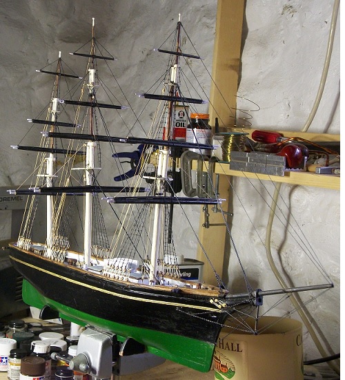
I haven't kept this log current, largely because there isn't much new or different in the way I'm approaching the rigging. The only real issue has been the stuns'l booms which are one continuous spar laid on top of the yardarms. That makes it difficult to provide proper rigging in hanging the yard on the mast, but I managed. On yeah, and the halyards, at this scale, were a pain in the neck. Try threading 2mm double blocks and keeping the lines from twisting! After this, 1:96 will look huge. At this point I need to rig the braces, hang the anchors, coil the lines.
- 40 replies
-
- 2
-
-
- restoration
- finished
- (and 1 more)
-
Michael, Fabulous idea! Nice looking subject; I hope you're able to get the information you need for your satisfaction, although the photo of Skipjack gives you quite a bit of information. This model will be about 28.5" long? With working engine? That build will be fun to watch, although I can't envision a crankshaft out of a bicycle chain! Tom
-
Jay, I love your videos. Yes, they are informative, but they are also very well produced. Micro-mark sells the silver solder paste that Bob mentions. It comes in a small tube. Tom
-
SS Vinal Haven by TBlack - FINISHED
TBlack replied to TBlack's topic in - Build logs for subjects built 1851 - 1900
John, Preiser has a wonderful looking eagle, but it's part of a set. The set costs $22.00. Maybe Andy and I could do a deal wherein I buy the set, take out the eagle, and sell him the rest of the set for his railroad club for $20? Sounds fair? Tom -
Pete, My aunt owns one of these, built in Eastport, Me. I think. I've sailed it a number of times. A mighty fine craft; good and solid; lots of mahogany. I'll certainly be following your progress. Did you decide on a scale? (sorry, just read the headline, duhh!) Tom
- 296 replies
-
- 1
-
-
- herreshoff
- buzzards bay
- (and 1 more)
-
SS Vinal Haven by TBlack - FINISHED
TBlack replied to TBlack's topic in - Build logs for subjects built 1851 - 1900
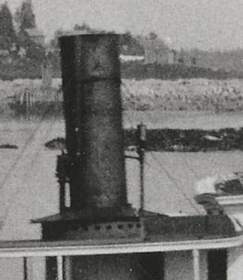
Andy, Steam blowdown muffler? Who woulda thunk it! Anyway, it's good to have you around. Google produced this How about it?: Tom
-
SS Vinal Haven by TBlack - FINISHED
TBlack replied to TBlack's topic in - Build logs for subjects built 1851 - 1900
OK, I'll take all these likes as an endorsement of my decision to follow Adrieke's suggestion. Great, but we're really not there yet. I still have some accoutrements to deal with around the funnel. Steam escape valve: On the left, what do you suppose that really looks like. The whistle on the right is no problem. Tom