HOLIDAY DONATION DRIVE - SUPPORT MSW - DO YOUR PART TO KEEP THIS GREAT FORUM GOING! (Only 13 donations so far - C'mon guys!)
×


usedtosail
-
Posts
2,405 -
Joined
-
Last visited
Content Type
Profiles
Forums
Gallery
Events
Everything posted by usedtosail
-
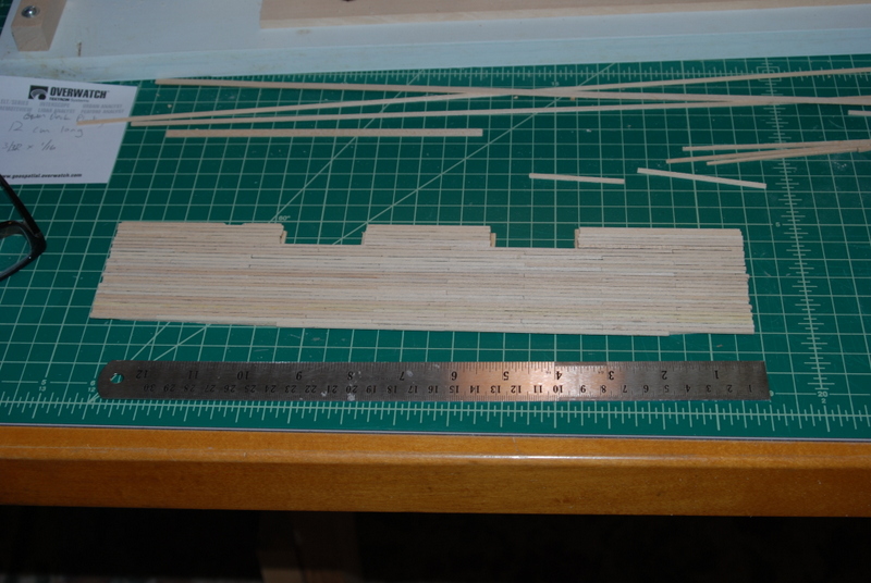
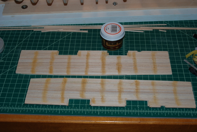
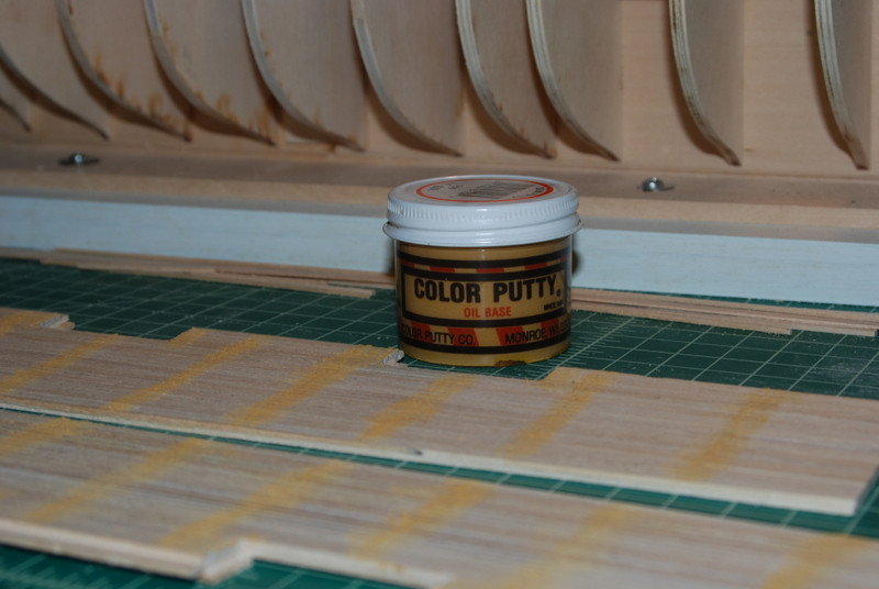
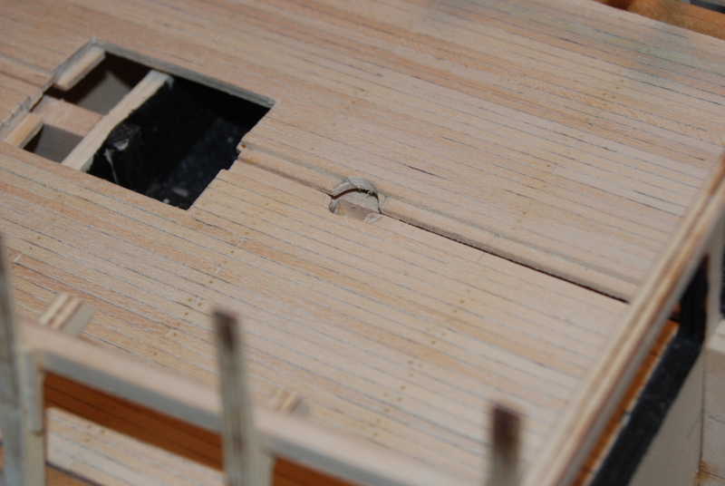
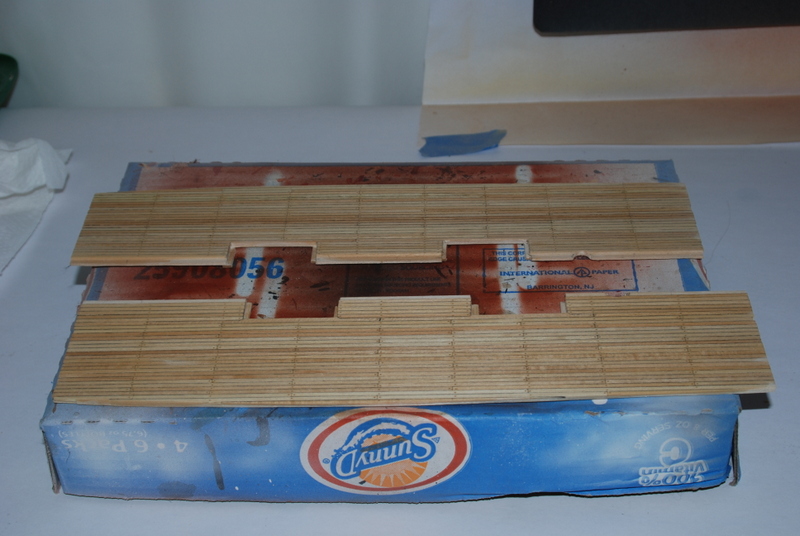
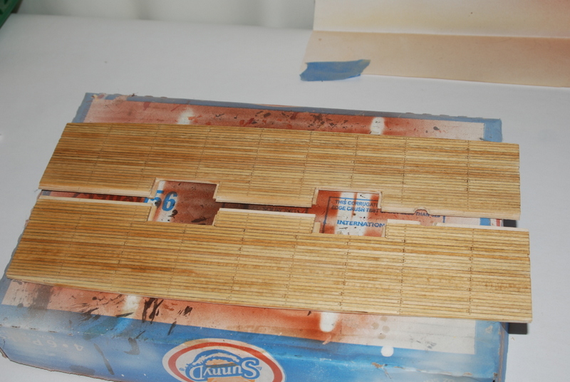
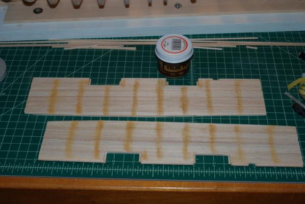
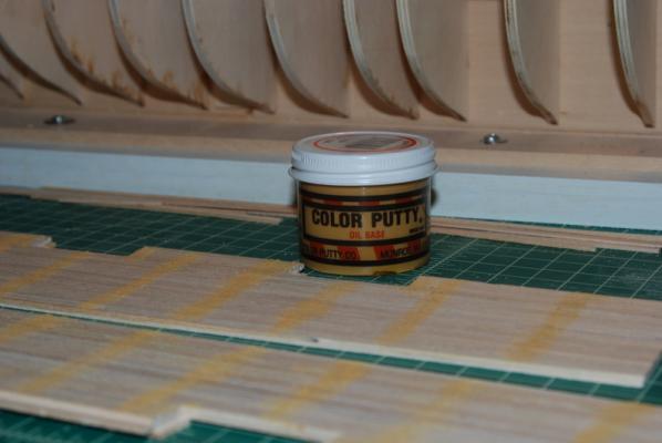
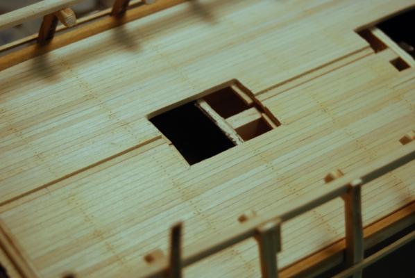
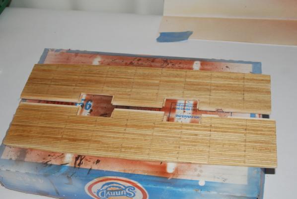
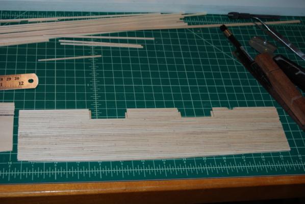
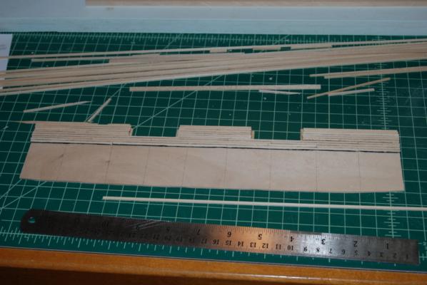
 Thanks Tim for your very kind words. I finished up the bulk of the gun deck planking last night, except for the three planks that will go down the center over the seam of the two pieces. First, here is the starboard side piece after planking and a first scraping/sanding, but before trimming the edges. After the edges were trimmed and it fit into the hull, here is the two pieces together, after filing out the hatch openings to fit the finished coamings. Now for the treenails. I taped the two sides down on the work table. I had added alignment marks so I could get them to line up outside of the hull. I then used some masking tape to mark each line of butt joints, and drilled one #74 hole in the planks that did not have a joint at that beam. I then took the tape off and drill two holes at each butt joint, one on each side of the joint. I also drilled holes at the ends of the planks at the hatch openings. I did not drill holes at the plank ends on the edges of the deck pieces, as the beam locations at each end are actually just off the pieces. When all the holes were drilled, I filled them with oak putty, which is different than wood filler. It is more oily and stays pliable. It looks horrible when it first goes on though: Here is the putty I am using: I then scraped and sanded the excess putty off. I don't leave it sit on the wood too long, as I think it might stain it after a while. The putty stays in the holes nicely though, which is why I like it better than filler. I then gave the decks a final sanding with medium then fine sandpaper. The first picture is with flash and the second is natural lighting which shows a little more detail: I then pre-stained the decks, after wiping them with a tack cloth. Here is how they look with just the pre-stain: After 15 minutes, I wiped off the excess pre-stain and gave them a coat of oak stain: I am happy with the way they came out, and will use this same finish on the spar deck when I plank that.
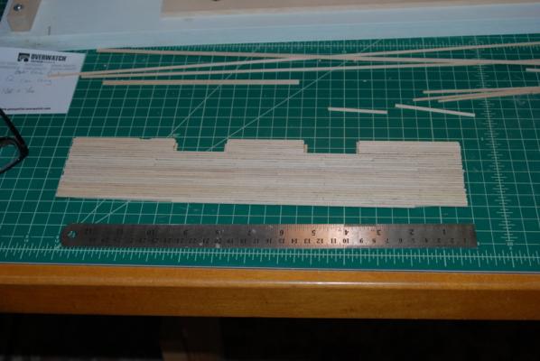


- 1,348 replies
-
- 9
-

-
- constitution
- model shipways
- (and 1 more)
-
I am sorry too Keith. He looks like a good friend. It has been a bad week.
-
Sorry Patrick, I don't. I would not count my research on this ship very deep. I have read the AOS book and looked over the plans on the Constitution site. Pretty much everything else came from build logs on this site. I made myself a series of notes as I read them but I did not keep track of which ones came from which sites. Given that, I already know that I am not making an authentic 1812 version. The gun port lids for one. As you have found, they either had full or no gun port lids in 1812. Because I am not building the whole gun deck, I want to use the dummy cannon barrels in those gun ports that won't have a real cannon. These need to have the closed split gun port lids to look good, otherwise you will see too much of the boxing behind them. My other option is to just put a closed full gun port lid on these, but I like the look of the split ones and I want to show all of the cannons sticking out of the gun deck. I hope this isn't too blasphemous, especially on such a well documented ship. Well, really I am surprised how much interpretation is still being done on it.
-
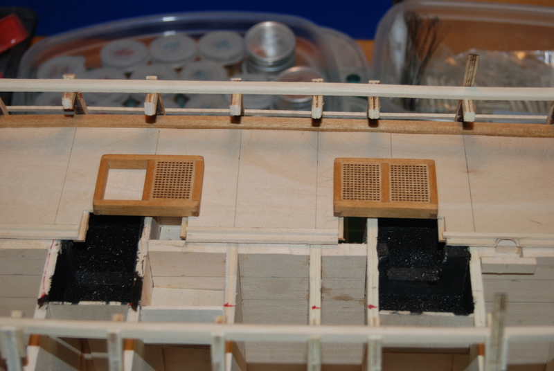
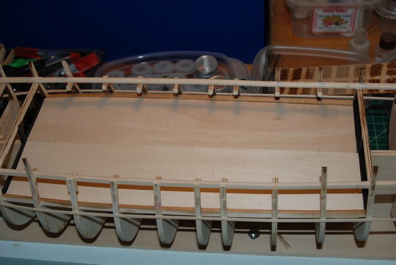
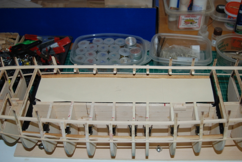
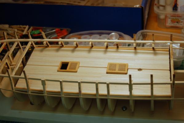
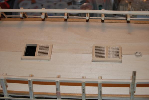
Thanks Patrick. It's nice to have such good friends here. I did manage to get some work done last week and this weekend, so I might as well bring you all up to date. First, here are the hatches to the berth deck completed with the gratings. I used three of the large gratings from the spar deck main hatch cover, which I cut apart. That hatch cover is not needed since the main hatch will be left open with the deck beams showing. I was quite pleased how these gratings cleaned up. This is actually the back side of them, which looked a lot better than the front side. The holes look round on the front side but square on the back. I stained these hatches with oak stain, which you can see in some later pictures. I then started planking the gun deck sections. I first pined a plank down the center as a reference, then put in spacers for another plank width on each side. I then cut and glued in one row of planks against those spacers on each side. These will be the starting planks that all the rest will be based on, so I made sure they were very straight and square. I left a plank on each side of the center plank so that when I put the two planked sections together later, I will have three plank widths to use to make sure there are no gaps in the center of the deck. We will see how this works out later. I drew lines at each of the bulkhead locations for the ends of the planks. I did move the location of the one bulkhead that is very close to its neighbor to be more centered between its neighbors, which is how I will show the deck beams for the spar deck. I have no idea why ME put those two bulkheads so close to each other, unless it has to do with the location of the main hatch (I am at work right now so I don't have the plans in front of me). Here are some pictures of the planking process and the finished hatch coamings and grates: Here is the port side deck section planked, before scraping and sanding. I used a black Sharpie on one edge of each plank as I installed them. I also used a three butt shift pattern. The planks lengths hit every three bulkheads and were nominally 20 cm long. This turns out to be a little long for this scale (~50 feet), but I didn't want to use planks that were shorter. The instructions for the hull planking say to use planks that are 4 bulkheads in length, but that would have been way too long. If you look closely around the hatch openings, you will see that I used wider planks that I cut down away from the hatch but left a little wider around the edge of the hatch. This is similar to what I have seen around gun ports on hull plankings, especially on Chuck's models. If I didn't do this I would have had a very narrow plank along the hatches, which I didn't want. I am not sure if this is authentic, but to me it looks better than a very thin plank. Here is the deck planking after an initial scraping and sanding, but I have not added the treenails yet. And again for symmetry, here is the starboard deck section being planked. You can see how the Sharpie looks before finishing. I do have to be careful not to get any on the plank surface, but if I do, I can turn the plank over and use the other side. Next is to come up with a way to hold these sections tight to the deck beams when I glue them down. I am also doing some trials for treenails, which with these narrow planks could be challenging.
- 1,348 replies
-
- 3
-
-
- constitution
- model shipways
- (and 1 more)
-
That's a lot of cannons. They look great.
-
Could you cut down the longest ones to make shorter thwarts?
-
Yes, thank you Michael. That was very informative.
-
Yes, the bottom of those bulkheads should be down to the rabbet line just above the keel, about where your keel holder is.
-
Bob, have fun with this build. You look like you are off to a great start. I had a ball with this kit and bashed it heavily with details from the AOS book. If you have any questions, I'd be happy to answer them if I can. I look forward to following your build. I didn't have a build log here, but there are a series of in build pictures here: http://shipmodeling.net/photopost/showgallery.php?cat=1391
-
It is with a heavy heart that I am dedicating the rest of this build to my younger brother, who passed away yesterday after a year's fight with lung cancer. Not only do I find this hobby extremely enjoyable, it is good therapy as well. RIP Matt.
- 1,348 replies
-
- 1
-
-
- constitution
- model shipways
- (and 1 more)
-
I chose the Model Shipways kit for its price - I got it at a really good price in one of the ME sales. I also like to modify kits, so I liked the idea of making it more like the sip was back in the day.
-
That is a good question, Alde. I really have no idea. I know these were built in different ship yards along the East coast, so that may have influenced the final outcomes. I haven't seen much detail on these other sister ships to the Constitution.
-
Thanks Patrick. I do not have plans for lighting these interior spaces. Most of this will be hidden by the boats over the main hatch, but I am doing it as a learning experience and practise mostly.
-
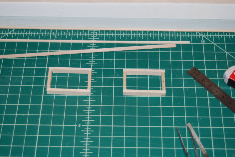
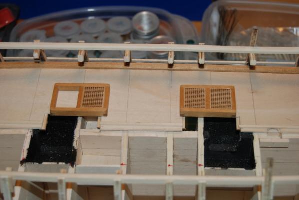
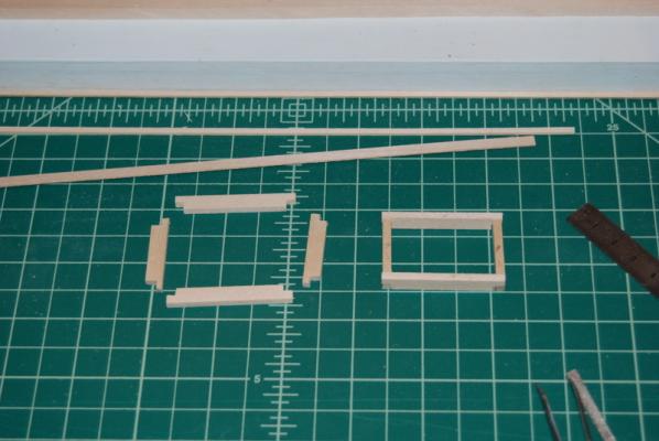
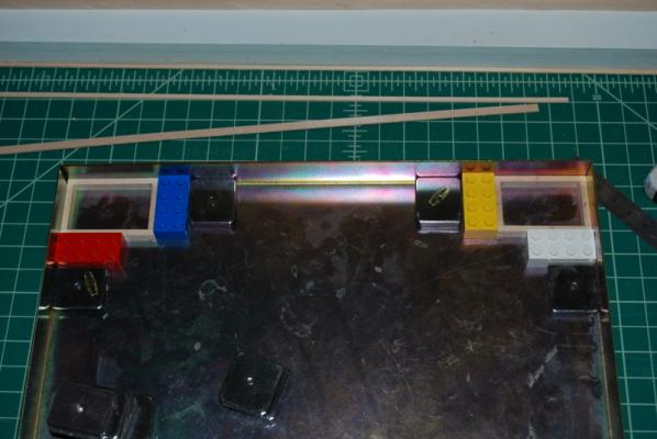
For the hatch coamings, I chose some strip wood that was high enough to fit above the deck base and deck planking height. For each hatch, I cut four pieces which all fit to the corners, then used a razor saw to cut lap joints into the corners. I made sure the lengths on the opposite sides were the same so they would be square, then glued them up using magnets and Legos to hold them square. Tonight I will add the center pieces.

- 1,348 replies
-
- 5
-
-
- constitution
- model shipways
- (and 1 more)
-
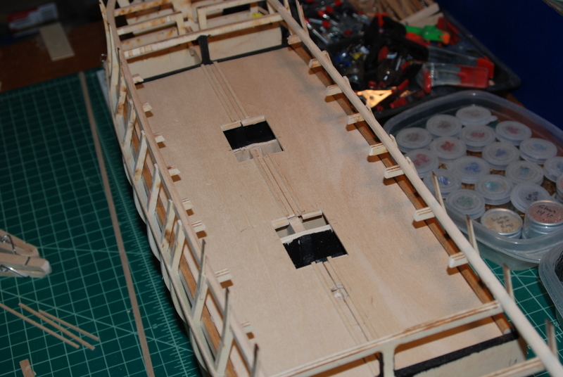
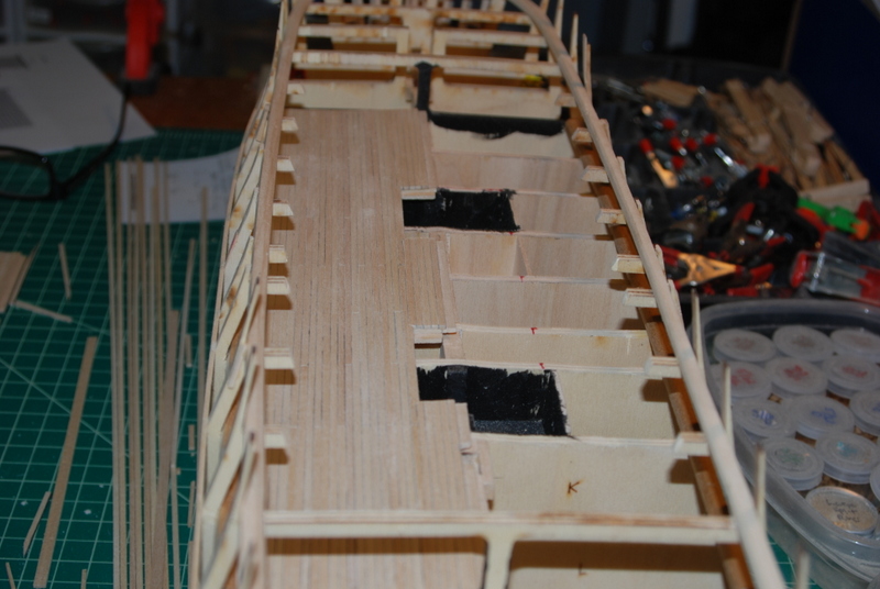
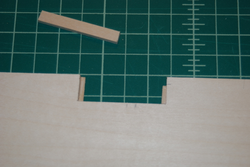
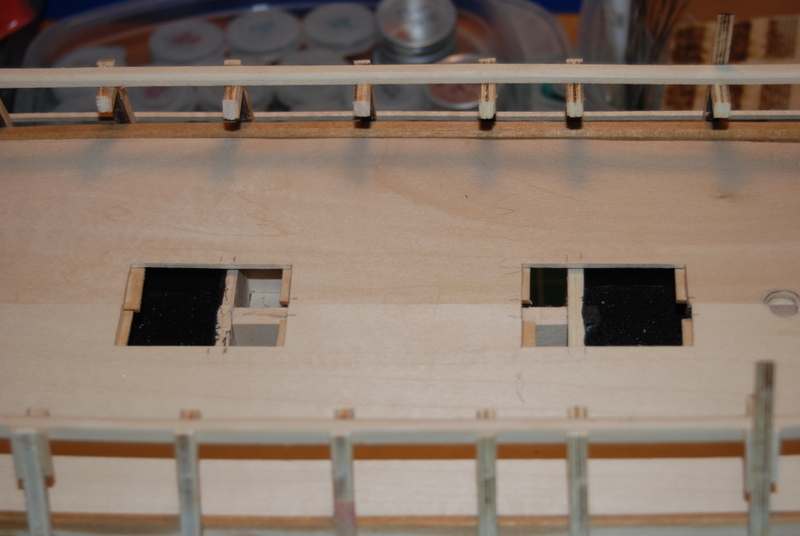
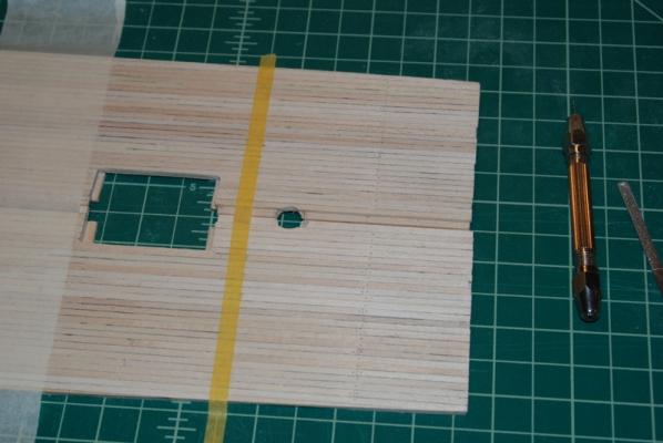
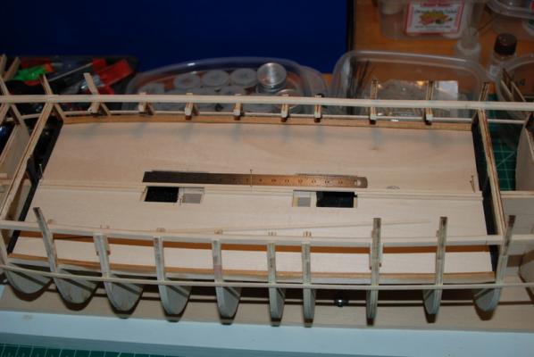
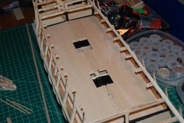
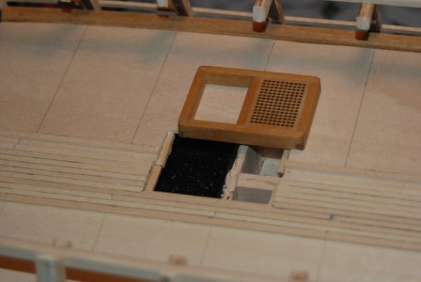
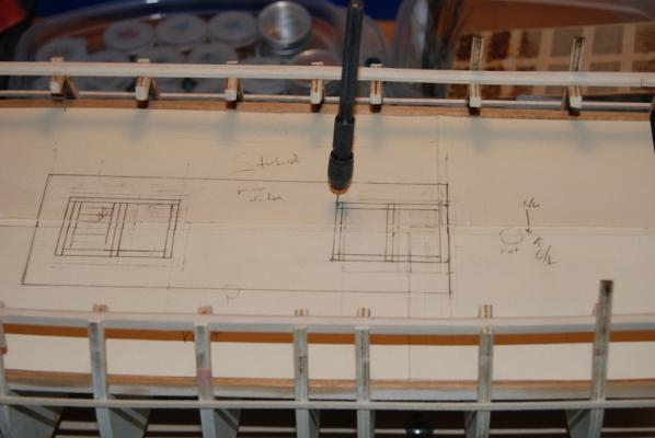
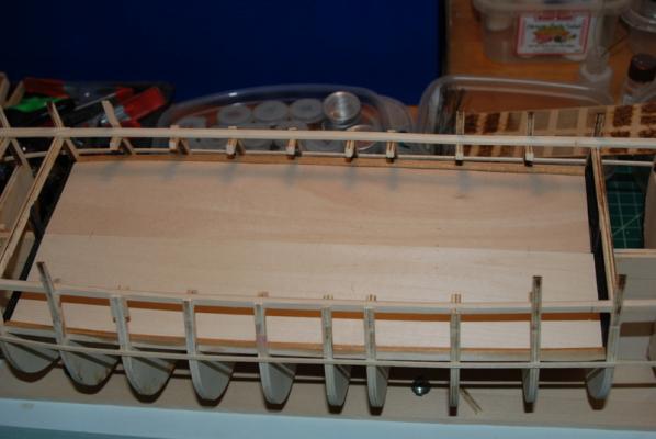
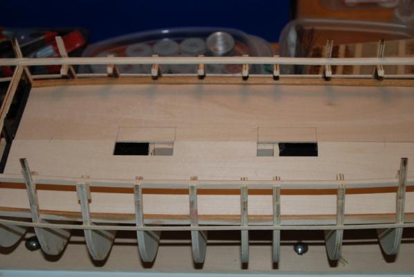
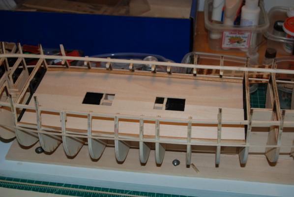
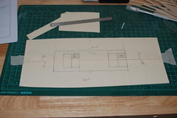
OK, where did we leave off? Oh yeah, getting the hatches from the gun deck to the berth deck more accurate. Here is a snippet of the plan that I was referring to from the CD and Constitution web site: So, I updated the gun deck template to this configuration. I was able to tweak these to use three of the large hatch gratings from the kit that would have gone over the main hatch, but since I am leaving that one open, I can use them here. I had to add some more boxing between the bulkheads to accommodate the new ladder location, which I painted black. I then used the templates to cut out the gun deck base, which I made in two pieces to fit around the spar deck beam ends. I cut them to length first, then cut the edges along the waterways and sanded them to get a nice fit. Once I was happy with the fit along the waterways of the two pieces, I cut them to meet at the centerline: Now it was time to cut out the hatch openings. To mark the hatch locations, I placed the base pieces and the templates into the hull, then drilled small holes at the corners of the hatches and where they met the centerline: I took the deck pieces out of the hull, drew lines between the holes, and cut the hatch openings out with an X-Acto knife. I gave the edges a little sanding, too: I wanted to make the hatch coamings for these so that when I plank the deck I can get a good fit at these openings. To support these coamings, I glued some tabs around the hatch openings, avoiding the bulkheads and center keel: .


- 1,348 replies
-
- 3
-
-
- constitution
- model shipways
- (and 1 more)
-
So true, Patrick. Sounds interesting. I know I have seen descriptions of some of the differences between 1797 and 1812, but I don't remember where.
-
Wow, I go away for a couple of days and miss a bunch of traffic on my own build log . Evan - thanks for providing the information regarding the CD to Patrick. I ended up downloading all of the material from the site so I have it on my computer not on a CD. I went through and renamed the drawings so I can find things easier, although there is an index of sorts. Shnokey - that is a great looking transom, and very much what I was thinking. I don't have a CNC machine, but will try to do something like that by hand, although not in relief. Is that a furnished captain's quarters on the other side of the windows? Just fabulous. Patrick - no worries. Make yours as similar as you like. It is very flattering to me. Maybe we can exchange some ideas as we go. It would be a lot easier to build to the AOS book, but as others have pointed out it may not be very accurate. The plans and photos on the CD (or web site) are very different but to me may be more accurate for the 1812 period, although as Evan pointed out they are from the 1920's.
-
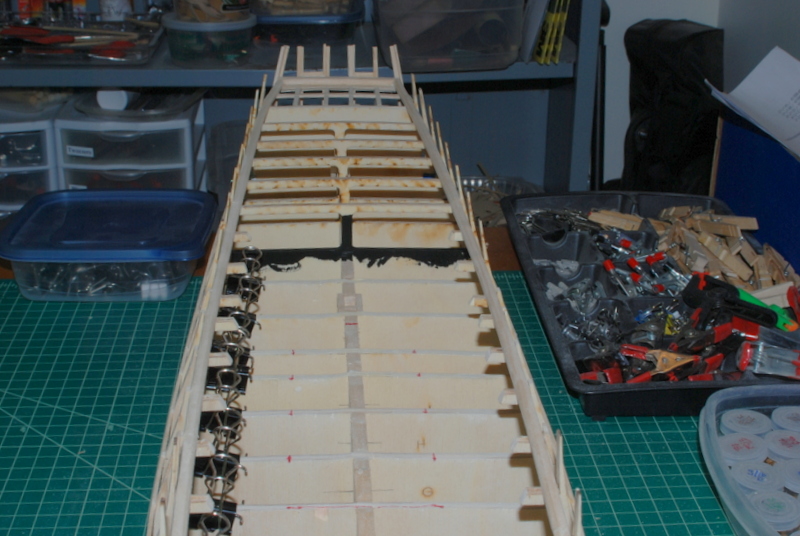
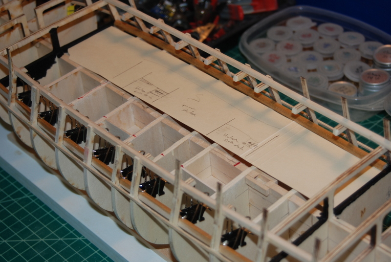
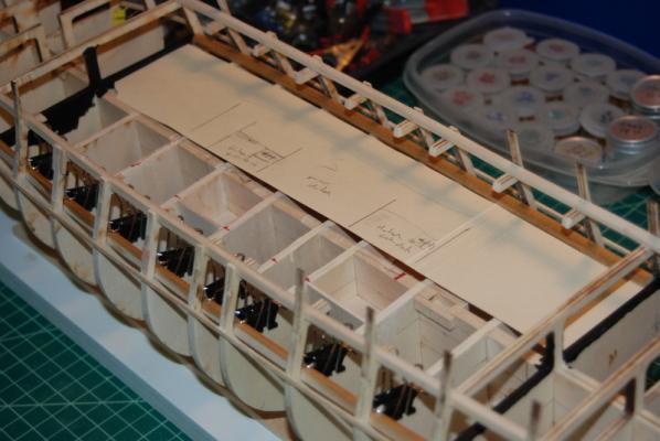
Thanks Steve. I am excited to be able to add this level of detail, especially on a model of this size, even if most of it will not be that visible. I glued in the gun deck waterways after staining them with golden oak: And here are the spar deck waterways. They add support for the bulwark extensions, which is why I waited until they were glued in before cutting the bulkheads: I then made a template for the gun deck base, which I will be cutting out of 1/16" basswood sheet. I need to make this base in two pieces because I wouldn't be able to get one piece past the beam stubs. I will cover the seam with the center plank. I used a compass to trace the curve of the gun deck waterways onto some manila folder: I then marked the locations of the two hatches that lead down into the berth deck. I took these from the AOS, but later I looked at the plans on the Constitution CD, which are a little different. I will be modifying them to match those plans. I did box in a few places where I was going to add ladders, but not all these will be used now. I will paint these boxes black to hide them. Thanks for the interest and the Likes.


- 1,348 replies
-
- 7
-
-
- constitution
- model shipways
- (and 1 more)
-
I did mine in one piece, but I don't remember how long. 4.5" seems about right. My success rate was about half at first. I soaked them for an hour or so then used a plank bender, which is a soldering iron with a larger tip. I had to heat them for quite a few minutes before they would even start to bend, but once hot enough they would go. Then they would stop bending, so I would resoak them for 30 minutes or so and heat them again. In a lot of cases they would go back to be straighter, but once heated again would bend back to where they were, then could be bent more. I took it very slow but still managed to break a lot.
-
Alde, another thing you can try is to scrape the planks with a scraper, especially the seams between planks. I used a #11 X-Acto blade that I held perpendicular to the hull to remove bumps and I was pleased with the way it worked. Then I sanded it like Keith and Steve suggest.
-
Welcome g. I hope you are going to start a build log when you start your Connie. I'd like to follow along. Following other builds on this site is the only way I would have attempted so much kit bashing. Thanks Patrick and Steve. Your builds are coming along nicely too.
-
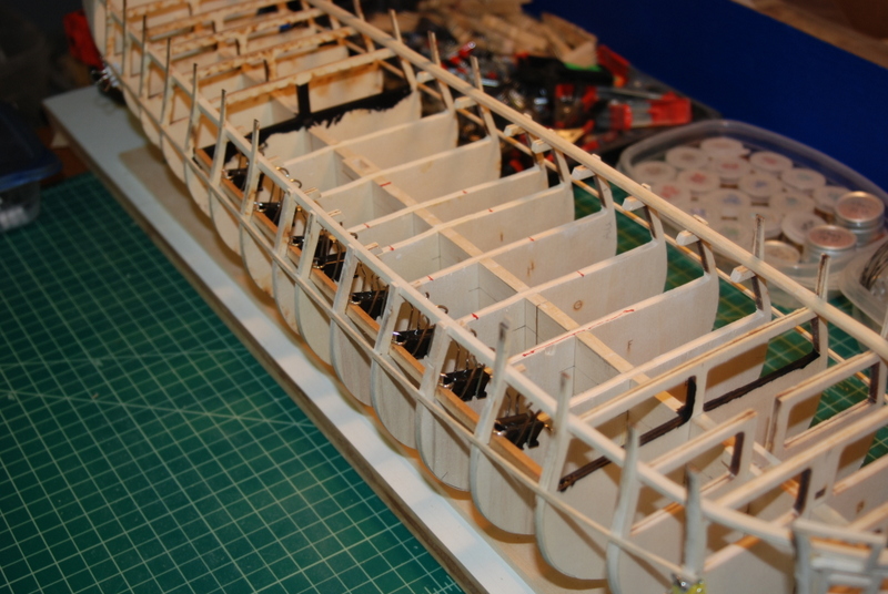
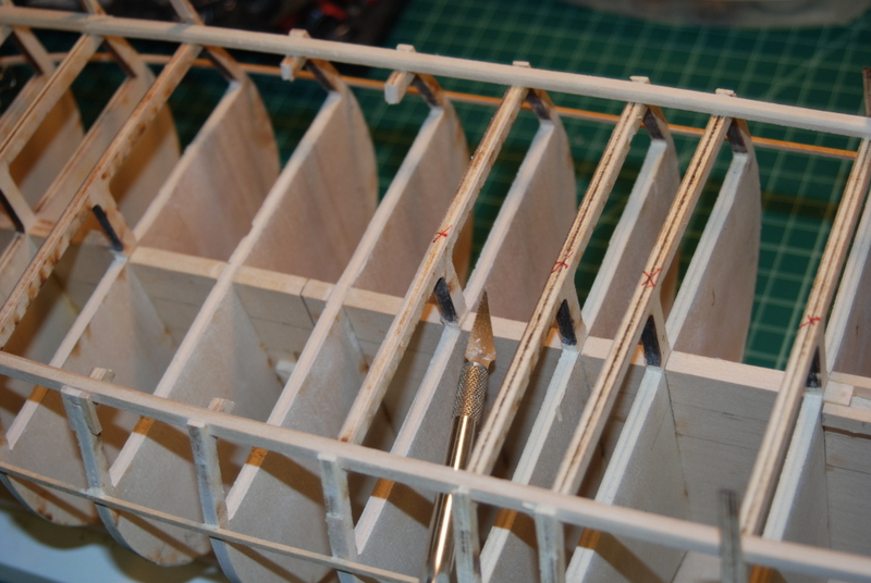
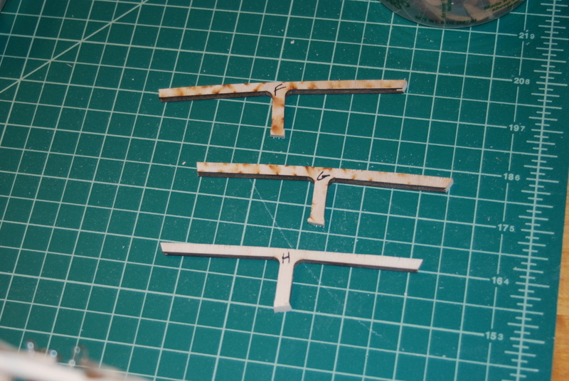
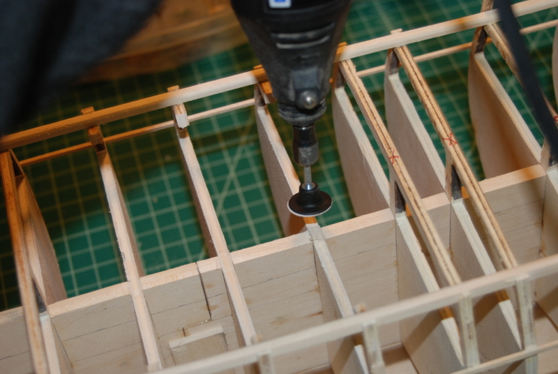
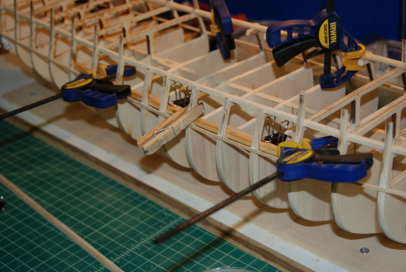
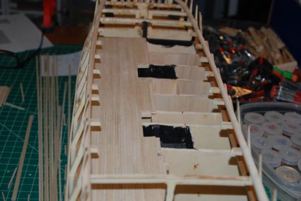
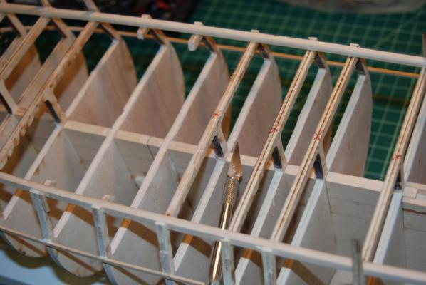
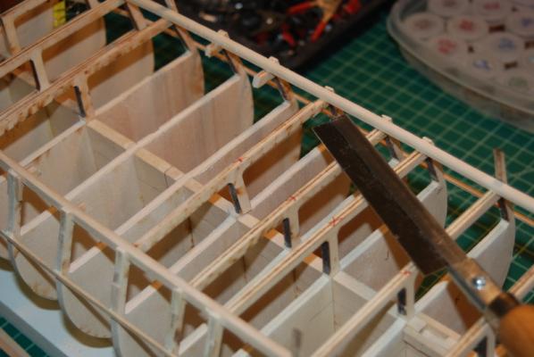
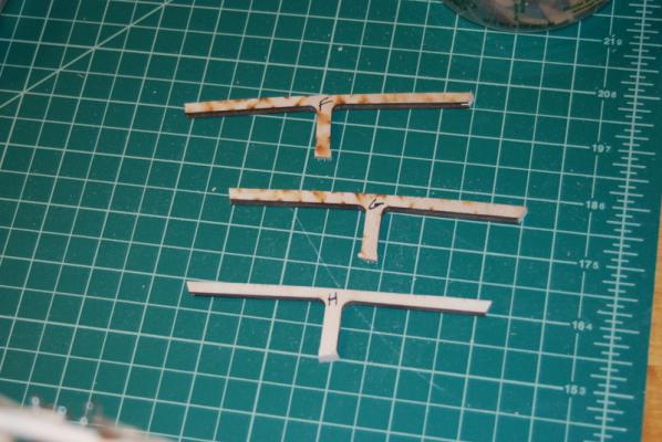
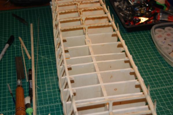
Thanks Patrick and Tim, and all the likes. Tim, those pictures are great. That stern looks very much like the Hull model. I will look at those closely as I design the stern on mine. OK, so tonight was the big surgery to remove the spar deck beams in the main hatch area. I am going to leave the hatch open, which means I need to add a gun deck. I removed the beams by first cutting the center supports at the bottom using an X-Acto saw blade. I then cut the deck beams using a razor saw to start and the X-Acto saw to finish the cuts. I cut these on an angle so that I can mate the new deck beams to these stumps later. These joints will be hidden under the deck planking so won't be seen (at least won't be seen easily). I marked each of the removed sections and put them aside to use as templates later for the new deck beams. Since these new beams will be showing, I will make them from solid wood, not the plywood of these beams. I ground the stumps left from the center supports using a sanding disk in the Dremel. Here is the area with the deck beams all removed. I soaked the starboard side gun deck waterway which I made when I was making the spar deck waterways, and clamped it in place to bend. The clamps on the other side are two bulkheads that I had to re-glue to the spar deck waterway, whcih came loose during the sawing process. Once the waterways are both in, I plan to make a false gun deck from some basswood sheet, which I will plank. I made these waterways higher than those on the spar deck to compensate for the additional height of the false deck. I feel better now that the major surgery is finished and I look forward to working on the gun deck.


- 1,348 replies
-
- 5
-
-
- constitution
- model shipways
- (and 1 more)
-
Ok, think about the planks that will wrap around the bow and the stern. they have to curve, so the outside edges of the bulkheads have to curve to match, so you get contact with the plank across the whole edge of the bulkhead. The plans for the bulkheads show a line on the ones that have to be bevelled. That line corresponds to the edge closest to the bow for the front bulwarks and closest to the stern for the rear bulwarks after you sand in the bevel. Just sand or carve straight from the existing edge to the line. Figure 1-4 in the instructions shows this pretty well. Leave a little extra for final sanding after you have all the bulkheads installed. This is where you will make sure the planks make a smooth run all the way along the hull, which is called fairing. I hope this helps.
-
All I can say Michael is Wow!