usedtosail
-
Posts
2,423 -
Joined
-
Last visited
Content Type
Profiles
Forums
Gallery
Events
Everything posted by usedtosail
-
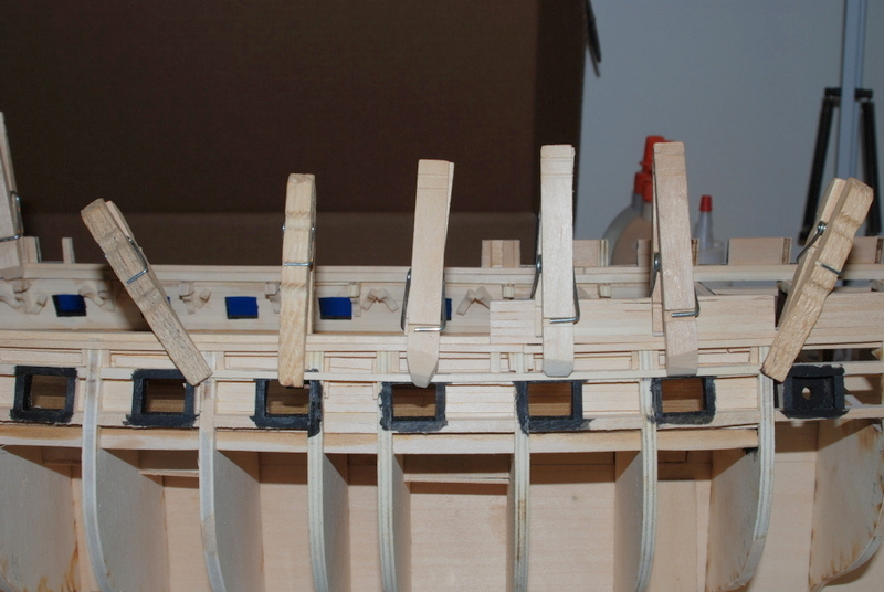
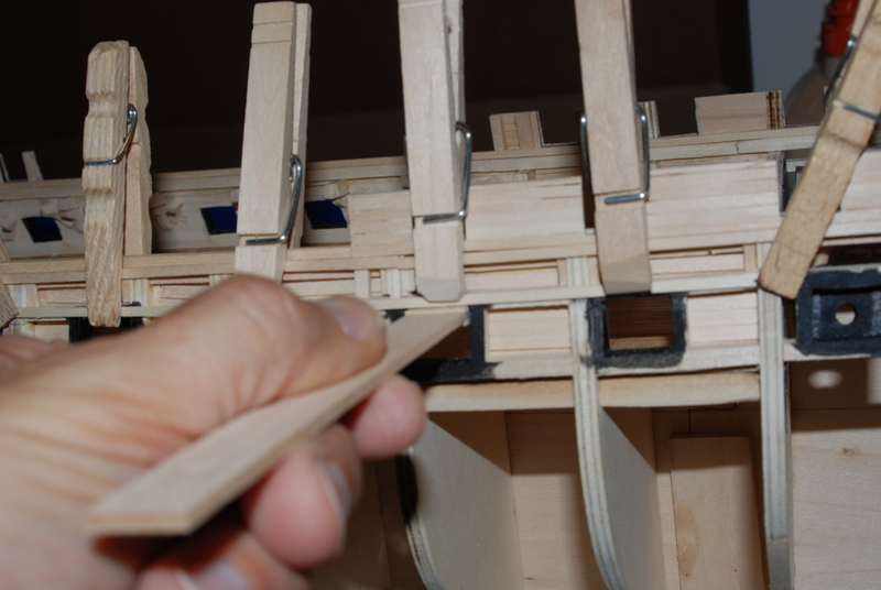
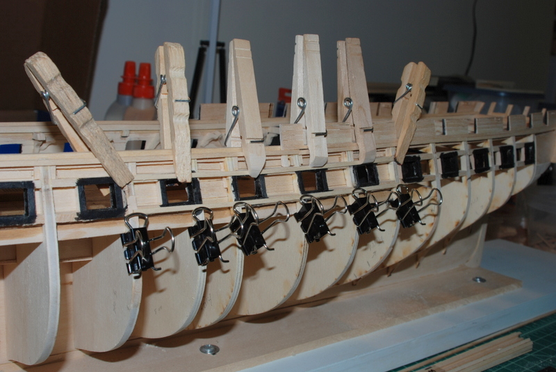
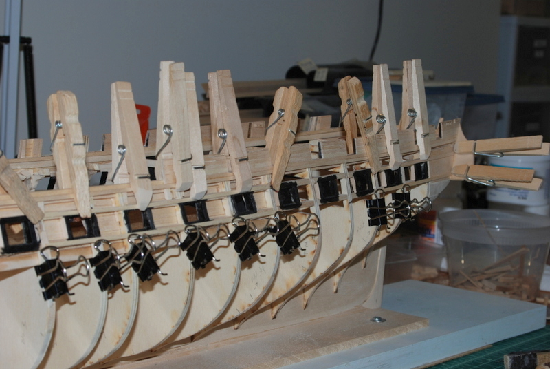
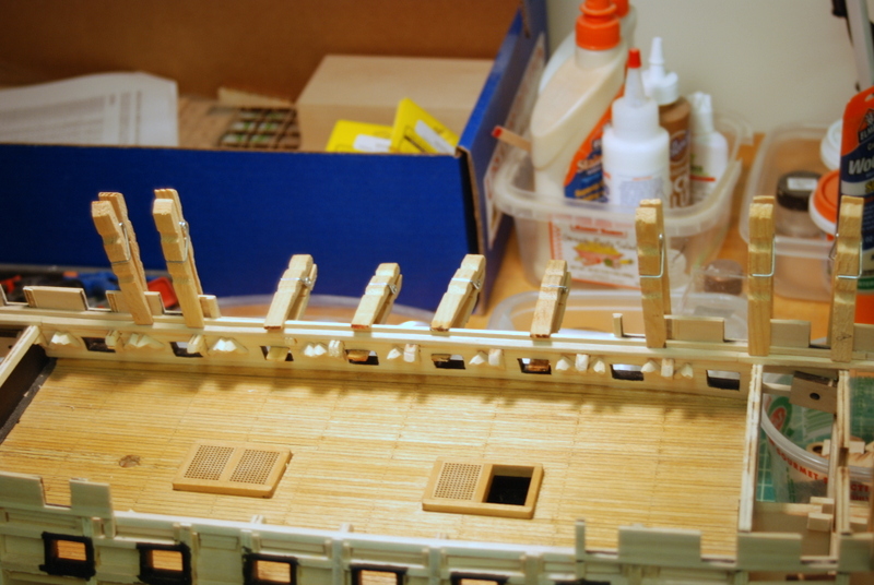
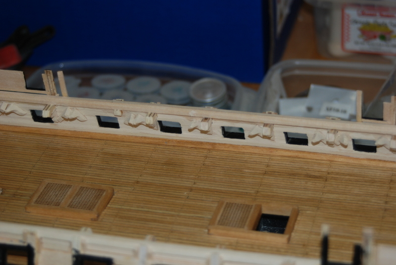
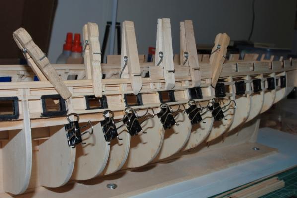
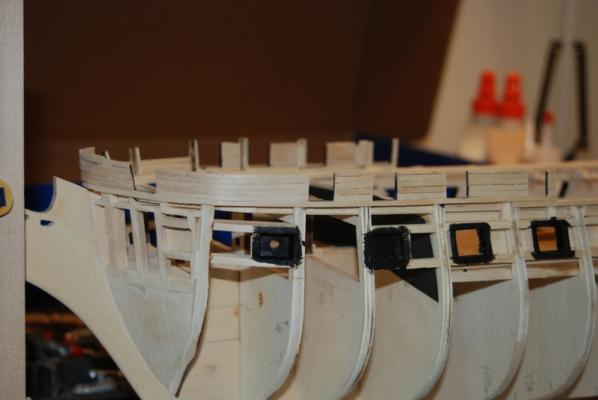
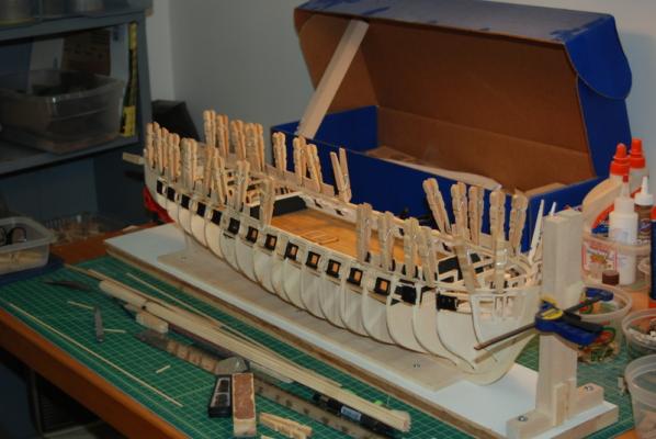
 As promised, pictures of the completed outer bulwarks. The inside planking for these will come later. Here is a view of the reworked spar deck water ways and plank sheer. So now I have started planking around the gun deck gun ports. I first calculated how many planks would fit below the plank sheer to the plank above the gun ports, leaving a 1/32" space all the way around them. If I use all 3/32" wide planks, I will have about a half plank above the gun ports, but if I use 1/8" wide planks for two of them and sand them down to about 7/64", they will fit nicely and still look about even. So with that figured out, I was able to add a plank above some of the central gun ports. I found a group where I could place a plank of a good length without having the ends right at a gun port, which wouldn't seem right to me. I made a little tool to help get the gaps consistent, which is just a piece of wood that fits into the gun port with a piece of 1/32" wood glued to it. I measure one gun port at a time, starting in the center and work my way to the ends. As I measure each port, I clamp the plank at that port, then go back and check that the plank didn't move after all the clamps are on. I also made sure the ends were at the correct height so that the adjacent planks can line up with the adjacent gun ports with a smooth run of the planks. After the two upper planks were added, I added two planks below the gun ports, using the same method, just different style clamps. The planking material for this hull is so narrow, it is going to take a long time to plank it. I'll try not to bore you all with too many updates once I get into the more routine planking, if there is such a thing.


- 1,354 replies
-
- 6
-

-
- constitution
- model shipways
- (and 1 more)
-
Thanks Pete and Rich. Rich - I learned the thumb tacks idea from your build log. It works great. It's been a long time wince the Admiral hung clothes in the yard. Now she just pushes the dryer button.
- 1,354 replies
-
- 1
-
-
- constitution
- model shipways
- (and 1 more)
-
Sorry, I should have included a smiley. Your stairs look great.
- 1,756 replies
-
- 1
-
-
- constitution
- constructo
- (and 1 more)
-
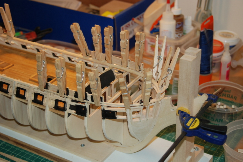
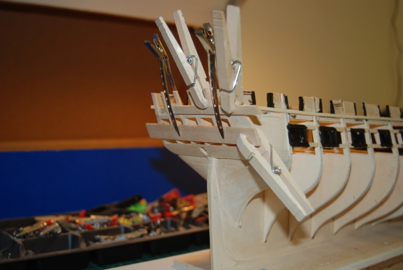
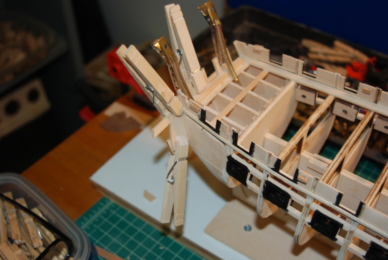
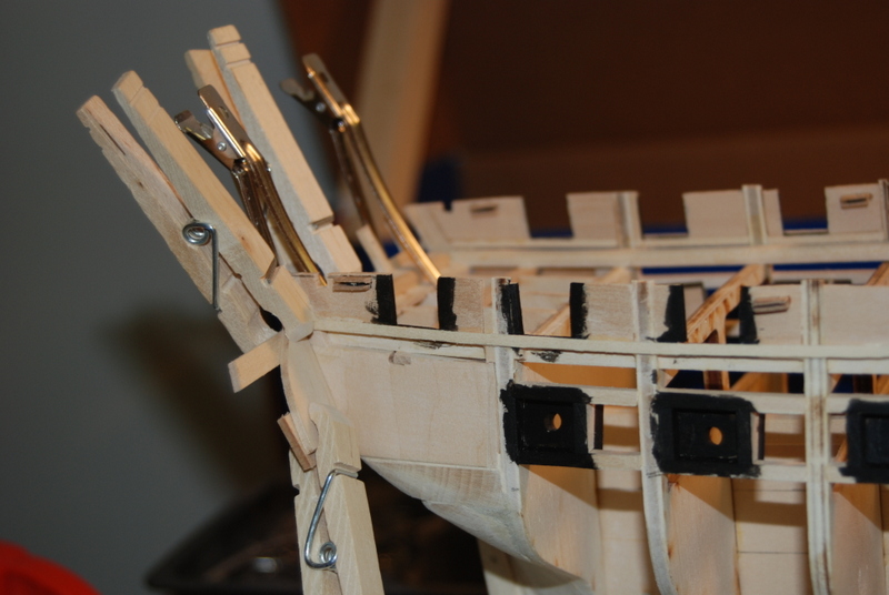
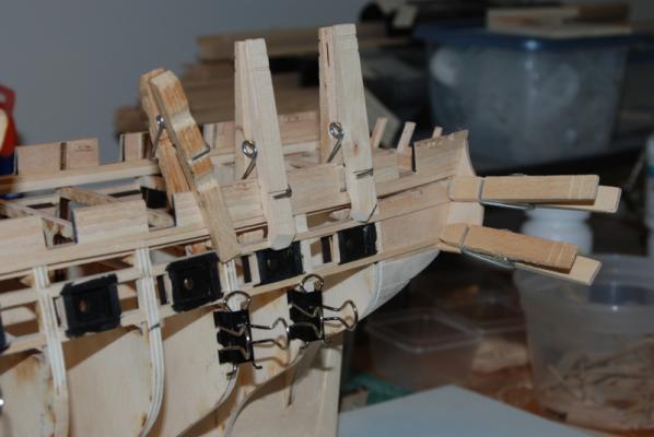
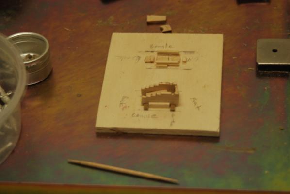
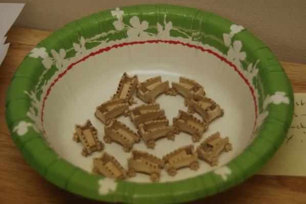
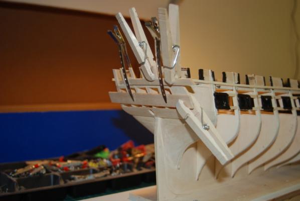
More pictures of clothes pin clamps doing their thing. As I was planking the starboard outer bulwarks, I also started making and installing the inner plank sheer pieces, first on the port side, then on the starboard side. The starboard bulwark planking was done exactly like the port side and the two sides are coming out pretty similar, especially around the fixtures like the through hull sieves. I'll have pictures of the finished bulwarks later. I soaked and heat bent two pieces of square basswood for the inner plank sheer across the bow. Here I am gluing in the port side piece and the starboard side piece is clamped in place wet to dry. You can see a piece of wood I clamped at the very bow so the ends of the two pieces made that last bit of curve. Before gluing these in place, I sanded the inside edge to match the angle of the bulwarks in the bow. Here is the port stern plank sheer piece glued in place. I placed scarf joints at the ends of all the inner plank sheer pieces, except right at the bow. These pieces will either be cut away at the bow or covered by the bow sprit. The clamps at the stern are holding the last layer of planks on the starboard bulwarks. After I installed the plank sheer pieces across the bow, I thought the waterways underneath them were too wide. I made the water way pieces from sheet stock and was not sure how much the plank sheer would cover them once installed at the angle of the bulwarks at the bow. I summoned up the courage to take a sanding disk on a Dremel extension to the sides of the water ways while in place to make them narrower. I first sanded them down, then cleaned up the sides with an X-Acto knife, riffler files, and a sanding stick. When I was happy with the width and sides, I filed the bevel back into the top and side using a riffler file. Here is how they came out, which you can compare to the first photo in this post. As I was checking the sides using some deck planks, I saw that the forward ends of the planks would be unsupported behind the first bulkhead. There are pieces between the first bulkhead and the bow that the ends of the planks can rest on, but not along the sides behind it. I didn't see anything in the instructions to add supports for the plank ends, but I think I better add some. What have other builders of this kit done in this area of the deck? Here is the plank sheer across the open waist on the port side. I had to make a decision here how to cover the top of the hull planking in this area. I had a couple of options that came to mind. One was to make the plank sheer wider in this area to cover the opening with one piece. I was going to go this way, but then thought about the color scheme in this area, The plank sheer will be the green color like the rest of the inner bulwarks, but the outer section i thought would look funny if it was green too. I think the outer section will be better black, as the rest of the hull, with a groove cut into the outer edge. So, I decided to make these as two pieces so I can paint them separately. I won't be adding the outer piece until after the outer hull is planked and faired, as it will be proud of the hull by a bit. If anyone has an idea of how this area might have looked in the 1812 era, please let me know. The only other reference I have is the AOS book on one of the cross sections in the waist area, but that looks more like a trim piece than a waterway and plank sheer. In between this planking and other work on the hull I have been making gun carriages for the gun deck cannons. I have all but one of them made to a point that they are roughly in shape, but need some clean up and painting. Here is the jig I use to assemble them, which basically holds the sides in place on the rectangular axles. I add the end and inner pieces while the glue is still wet on the sides, then remove it from the jig before the glue totally dries so I don't glue it into the jig. When the glue is completely dry, I file the ends of the axles that stick out from the frame round for the wheels. The wheels are just pushed on for now and not glued on yet, and the axles still need to be trimmed once the wheels are in place. Here are the carriages made so far. I am finished with the bulwarks planking and will now start planking down to and around the gun deck gun ports.


- 1,354 replies
-
- 8
-
-
- constitution
- model shipways
- (and 1 more)
-
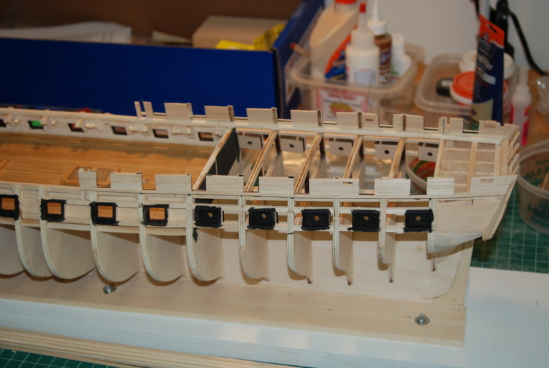
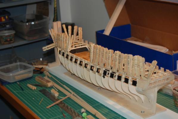
I finished planking the port side outer bulwarks. I set a compass to the height of the bulwarks above the plank sheer and drew lines across the sections. In most cases, I had to remove about a half a plank width, so I carefully used a razor saw to cut off most of the excess, then sanded the tops fair so the main rail pieces will run smoothly. I thought at one point I would have to lower the sieves, but I had just enough clearance for them when sanded. I left the planks at the curve of the bow as is until after the starboard side outer bulwarks are planked. I was able to sand these bow planks smooth without any big gaps, so I am pretty happy with the planking so far. I was also happy that the sides of the spar deck gun ports all have pretty much the same shape and width. Here is how the port side came out. The starboard side is still just the inner support pieces in these pictures. Now to repeat on the starboard side, and hope that the two sides come out similar.
- 1,354 replies
-
- 5
-
-
- constitution
- model shipways
- (and 1 more)
-
Thanks Evan for the information on the whaleboats. I'll not be adding them to my build then, but will add a gig or cutter like the article mentions.
-
Pin pushers for planking?
usedtosail replied to Landlubber Mike's topic in Modeling tools and Workshop Equipment
Hi Mike. I didn't buy any nails with the pliers, but have used them on all kinds of nails that I have received with various kits, as well as regular sewing pins. -
Best glue for rigging: CA & GS-Hypo
usedtosail replied to Beef Wellington's topic in Masting, rigging and sails
Check here: http://www.consumercrafts.com/store/details/catalog/jewelry-adhesives/GS100?CAWELAID=120132600000003290&gclid=CP3M5s6C0r4CFZJr7AodUyEA8w -
Pin pushers for planking?
usedtosail replied to Landlubber Mike's topic in Modeling tools and Workshop Equipment
I bought a pair of these and really like them: http://www.micromark.com/pin-insertion-plier,10735.html -
Thanks for the tip, Don. I'll have to try that sometime.
-
I have managed to get most of the port side outer bulwarks planked. The area between the second gun ports across the bow is still being worked. But, I was able last night to sand the planks flush (almost) with the sides and bottom of the gunports. I have left a little material there to sand off when I do the inside bulwark planking. When I sanded down the through hull sieves, the piece of dowel I had on the inside started to be sanded, so no longer looked round. I had made these too wide. So, I popped them out and made new ones, using a smaller diameter dowel inside. I also didn't like the old ones because I didn't completely frame them on the sides, so I took the opportunity to add those side pieces to these. Here they are installed in the slots and sanded flush. I am going to have to use some wood filler on these planks, but not too much. I think the bow planks will need more, as getting them to line up nicely along the sharp curve was a pain. Should have pictures of that area soon.
- 1,354 replies
-
- 7
-
-
- constitution
- model shipways
- (and 1 more)
-
Nice work on the stern. I can't wait to see how this will look compared to the stock stern in the kit. Stay calm. Modelling is a big help (most of the time).
-
That shot would make an excellent book cover. Just saying...
- 3,618 replies
-
- 2
-
-
- young america
- clipper
- (and 1 more)
-
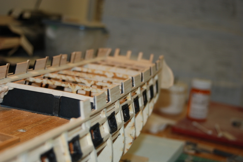
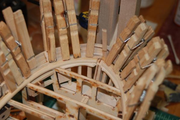
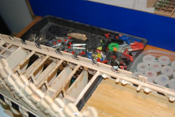
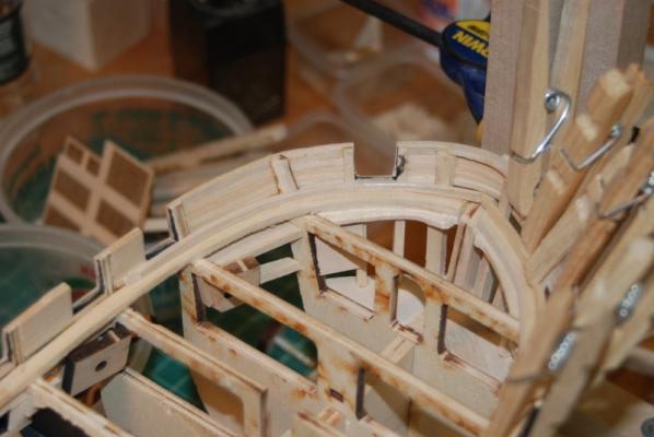
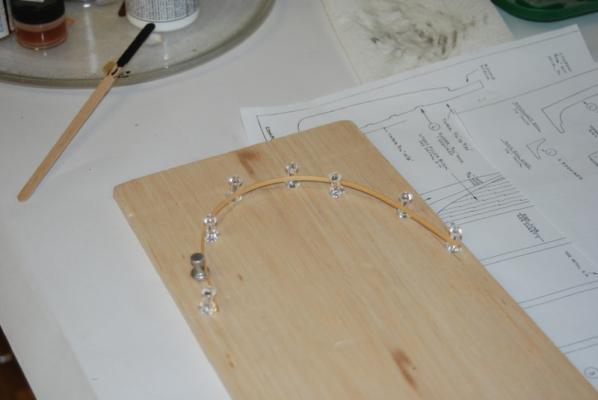
Finally some outside planking going on. I am starting with the easy part, the outer plank sheer and planks to the main rail. I installed the plank sheer in a couple of pieces, with a single piece wrapped around the bow. I first soaked and bent it around the bow and then glued it after it had dried in place. In these pictures the plank sheer is being glued on except the bow, which is being bent and drying. At this point I realized that I had not added the back pieces for the quarter galleries, so I dug the laser cut top pieces out and made the two bottom pieces. I bevelled the edges of these to fit together at the angle of the knuckle in the transom. As I was dry fitting them, I came to the conclusion that the bulwarks were too high at the transom. I used a steel ruler to extend the tops of the solid pieces along the sides to the transom and and marked this as the top. The backs fit perfectly then, but I had to trim off some of the last bulwark pieces at the transom, which I was able to do with a razor saw and some sanding. I then just had to extend the slot for the stern bumpkins. The rear sieves are now much closer to the top rail, but looking back on the plans and pictures of the actual ship, they are just under the rail, so it is all good. I needed a way to secure the gallery backs so they would be flush with the transom and stay at the right height while the glue dried, so I clamped a couple of planks to the transom that I could clamp the backs to. Here are the backs being glued in place: The bottom pieces I just held in place while the glue tacked up. Here are more planks being applied between the spar deck gun ports. This shot has almost all of the clothes pin clamps I have being utilized: For the pieces that I need to curve around the bow, using the model itself was not satisfactory as there is no solid piece across the bow curve at this level, so the next piece I bent came out too flat in the front. I was going to make a solid block the same shape as the bow, but just happened to see a set up yesterday in Hipexec's build log (thanks Rich) that was much easier, using push pins to define the shape and hold the planks. I had some balsa sheet that I used as the base and traced the bow from the plans to it, then added push pins to hold a soaked plank: We will see tonight how well this matches the actual bow, but it should be close.


- 1,354 replies
-
- 8
-
-
- constitution
- model shipways
- (and 1 more)
-
That is a great turntable. Just be careful after you add the bowsprit being that close to the wall. I also like your bending method with the push pins. I happened to borrow that technique just last night on my Conny build, and it worked great. Thanks for the tip. And you Constitution is looking really good. Nice work.
- 1,756 replies
-
- 1
-
-
- constitution
- constructo
- (and 1 more)
-
I am interested to follow the work of a real craftsman here.
-
For what its worth, the Model Shipways plans have them coming in on the spar deck.
-
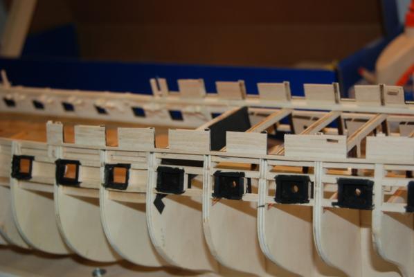
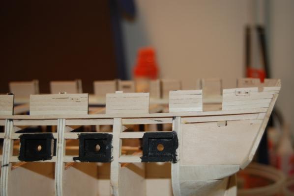
Thanks Guys. Patrick - the reason I went with black was aesthetics, I guess. Since the spar deck inner planking will be green, and the gun deck inner planking is off white, having red inside the gun ports just didn't seem right. So, I went with black as on the current ship.
-
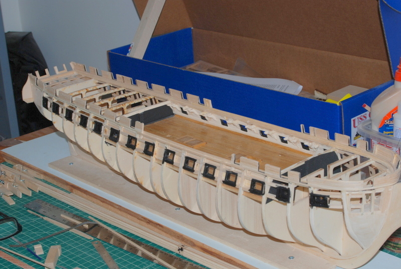
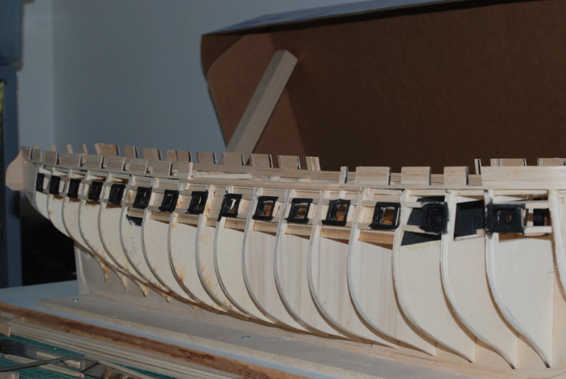
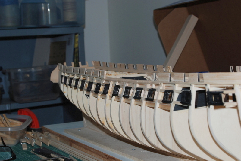
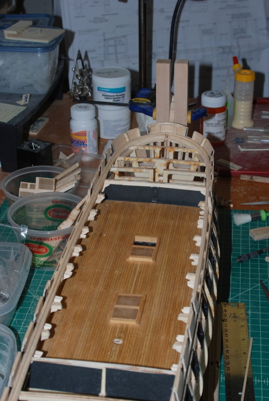
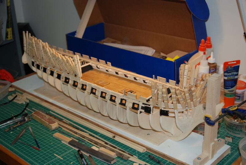
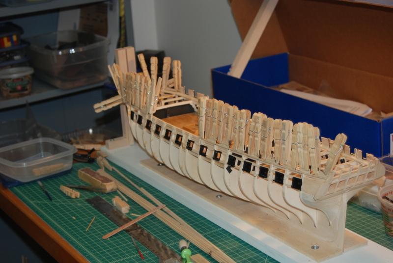
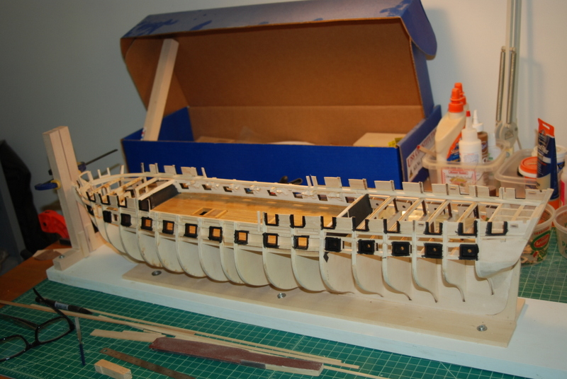
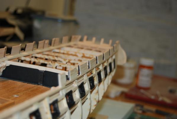
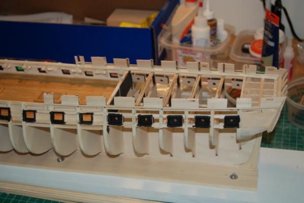
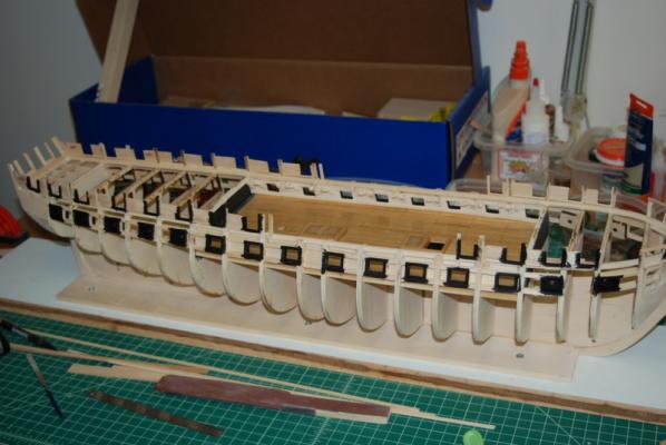
OK, now the frame is really all set to start planking, which will have to wait a few days as I will be away this weekend. I painted the insides of all the gun ports and around the outsides of them too, although only the gun deck ports really needed this for the recessed planking that will go around them. Despite the great research and discussion that is going on in some of the other Conny build logs regarding lack of lids in 1812, I want to add the gun port lids so that I can close off the ports with the dummy cannons. So, I will be leaving a recess around the ports for the lids to fit in. I was most concerned about the paint around the inside edges of the gun deck ports, since I had already painted the inner planks. I was quite pleased with the results, with not too much touching up of the off white paint needed. Finally, I was finally able to trim the bulwark extensions to almost the real height. I left them a little long to sand down to the planking later. I also trimmed the transom extensions at the same time, although I left them a little taller. Hopefully, the next update will show some planks on her.


- 1,354 replies
-
- 5
-
-
- constitution
- model shipways
- (and 1 more)
-
Sorry to hear of your injury Patrick. Hope it heals quickly.
-
What glue to use?
usedtosail replied to rshousha's topic in Painting, finishing and weathering products and techniques
Hum, I think I was using the term white glue as a generic term. I meant wood glue, which is yellowish but dries clear. -
What glue to use?
usedtosail replied to rshousha's topic in Painting, finishing and weathering products and techniques
I am currently building the Constitution but still a long way from rigging. For previous models, I did use CA for knots, except for the ratlines, which is where I used the Dullcore lacquer. I had a few of the end knots on the ratlines come undone, so I may try the white glue for them on this build. -
What glue to use?
usedtosail replied to rshousha's topic in Painting, finishing and weathering products and techniques
Thanks Rick. This is great information, as I have an allergy to CA glue too. I have been using Dullcote lacquer on knots but have not been too happy with the holding power. -
What glue to use?
usedtosail replied to rshousha's topic in Painting, finishing and weathering products and techniques
Hi Rick. Do you use the white glue full strength on the knots and lines or do you dilute it? Thanks.