usedtosail
-
Posts
2,421 -
Joined
-
Last visited
Content Type
Profiles
Forums
Gallery
Events
Everything posted by usedtosail
-
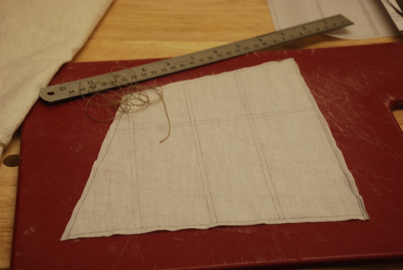
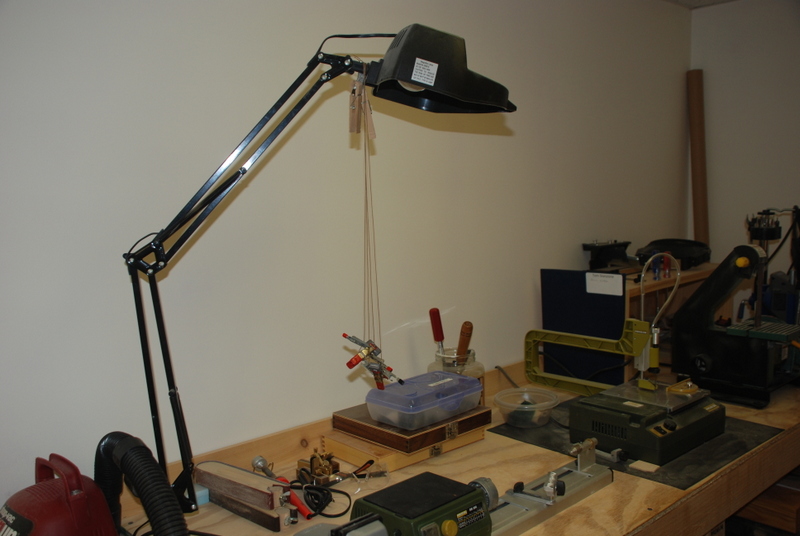
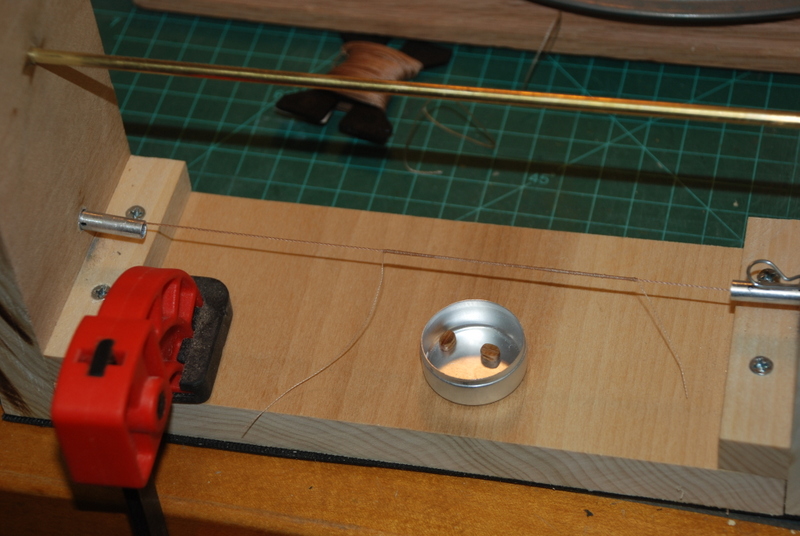
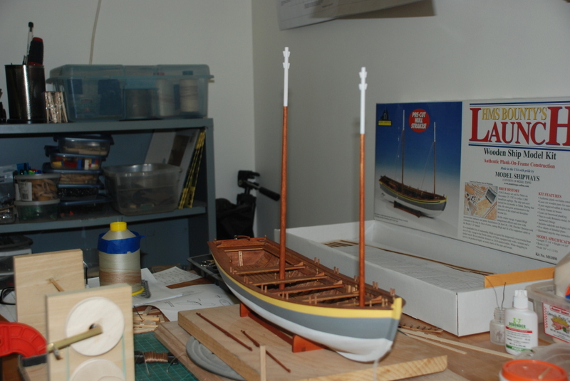
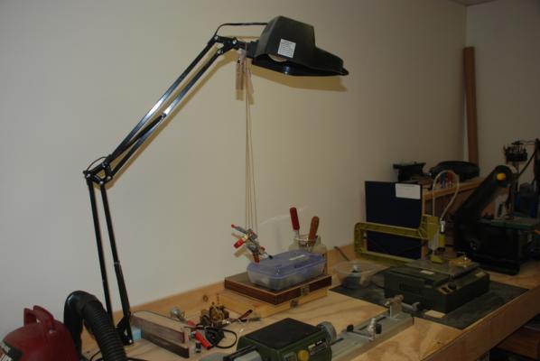
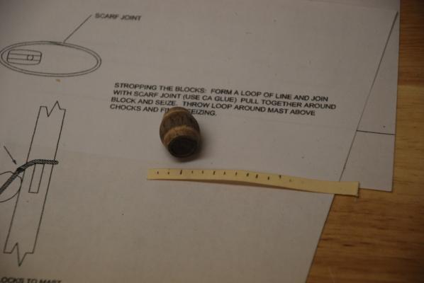
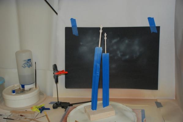
 Other stuff I am working on. I transferred the shape and details of the fore sail from the plans to a sheet of paper, which I traced onto the supplied sail material. I applied Fray Check along the outside lines, then carefully cut the sail out. I want to add a bolt rope along the outside edges. I am still experimenting with gluing or sewing the bolt rope to the edge. I am leaning toward sewing if I can get it to look good. Gluing was not working out too well on some scrape material. I ran some line for the mast shrouds through bees wax, ran them over a light bulb and through my fingers to get the wax into the line. I then hung them with weights to straighten out: I served some line for the first time in my home made serving machine, to use to strop the two blocks for the spar halyards. I coated the serving in varnish to hold it together. I am hoping they will stay together when I strop the blocks. I sanded the two blocks to get them to look more realistic, too. Finally, I finished finishing the masts. The dowel was not taking the stain well, so I ended up painting them with a very diluted mixture of burnt sienna and raw umber acrylic paint. I am really happy how they came out. I masked off the "natural" part of the masts and used a brush to get a good edge at the white tops. I am not sure which of these projects I will do next, maybe all at once still.
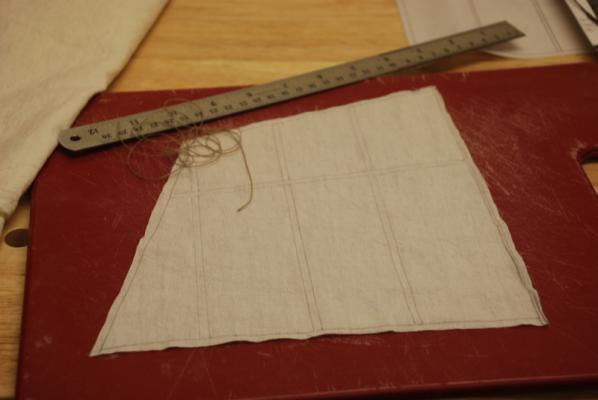


- 153 replies
-
- 2
-

-
- model shipways
- bounty launch
- (and 1 more)
-
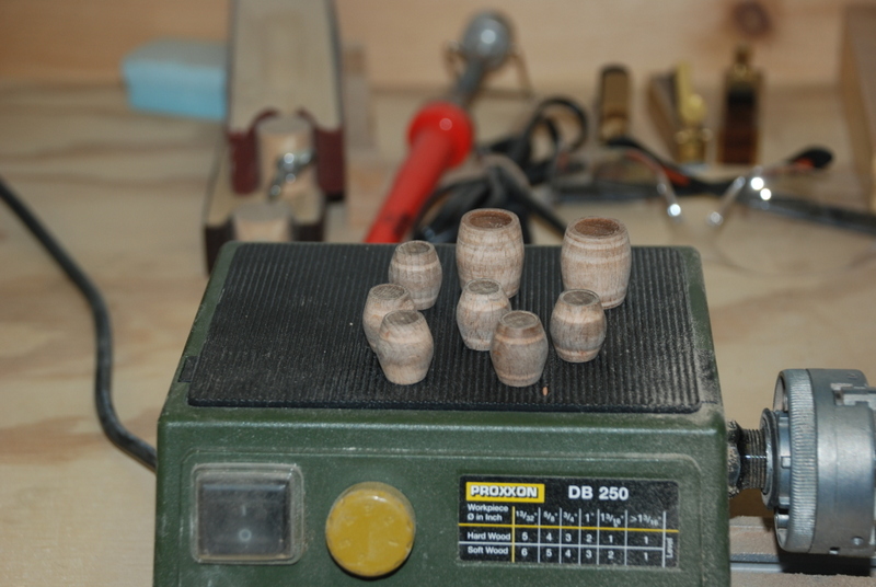
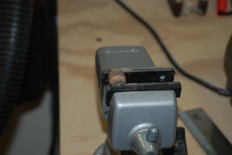
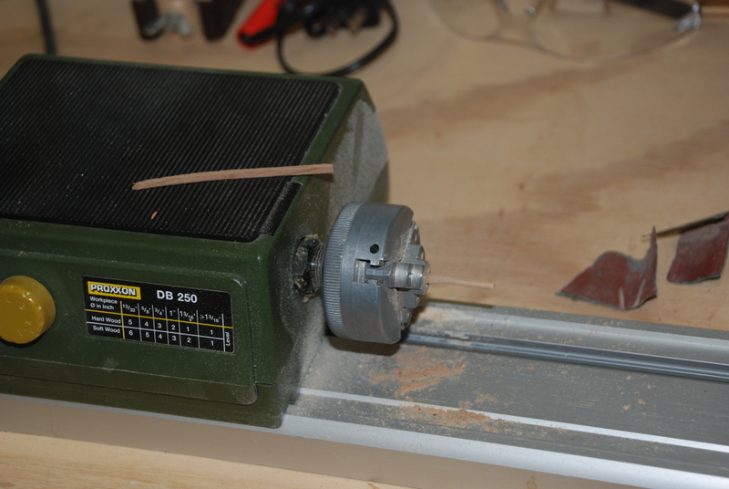
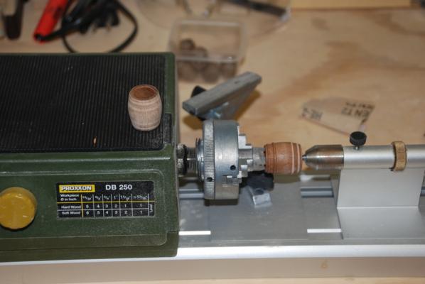
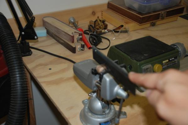
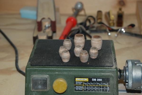
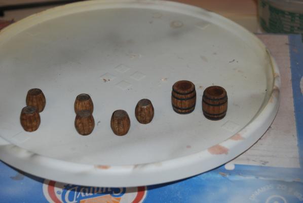
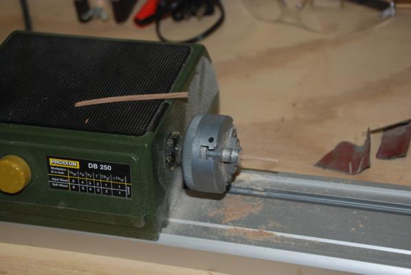
For some reason, I have been working on a bunch of different things for this build. I usually like to finish one part before moving to the next, but there is a lot of experimentation going on that has got me excited to see what will work best. First, here is how I am working the barrels supplied with the kit. I first scraped and sanded the raised hoops off in the lathe: Here is how they came out: I then made a tick strip to divide the small barrels into 24 equal parts, then transferred the marks to a barrel. I used a similar tick strip for the larger barrels. I then put each barrel in a vise and used a razor saw to score a line at each mark, turning the barrel in the vise after each line (sorry for the blurred picture. Next time I'll use a tripod) I then painted the barrels with a very diluted raw umber acrylic paint, and added black paper strips for the rings. I ended up removing the strips on the small barrels because they were all crooked, so I repainted the barrels and will try again, going more slowly next time. The large barrels came out OK. I really like how the individual staves can be seen now. More stuff in the next post...

- 153 replies
-
- 1
-
-
- model shipways
- bounty launch
- (and 1 more)
-
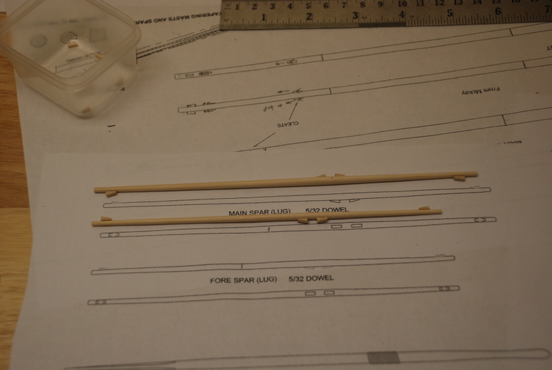
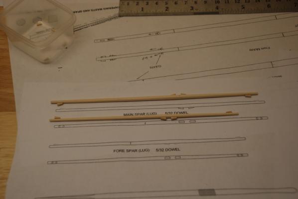
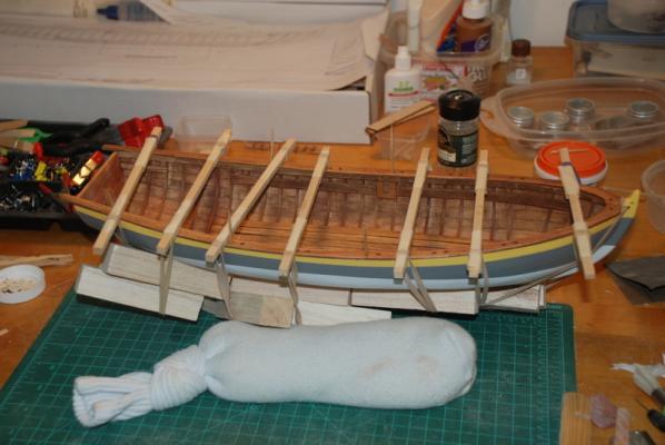
OK, as promised, here is the reworked thwart. It looks much better now. You can also see the stained thole pins and belaying pins. Here are the masts being tapered in the lathe. I mostly used rough sand paper to get them to shape, then a fine sandpaper to finish them. I roughly shaped the cleats off the mast using a straight razor to cut them at an angle, then I did the final sanding using an Emory board while they were on the mast. Here are the two spars with their cleats, which were made the same way. Finally here are the masts getting a coat of primer on the top sections before I paint them the same off white I used for the hull.
-
Thanks Bob, Pete and Mick.I really appreciate your support of this build. After posting the last set of picture, that one thwart with the obvious saw marks on the edge jumped out at me, so I removed it and sanded that edge down to remove them. I am in the process of restaining that edge, then I will glue it back in. I have also stained the thole pins and added the belaying pins, which I know are probably not realistic, but I like the look of them. I had to drill out the pre-drilled holes in the various parts to get them to seat all the way down, and also because a few of the nails holding the mast partners in place went through the holes in the middle of the mast thwarts. Once I finish staining the thwart and glue it back in, I'll take some updated pictures. In the mean time, I have tapered the two masts and added the cleats. I am going with the cleats for the shrouds near the top of the masts based on what I saw in other build logs. I have masked off the bottom portions of the masts and primed the tops, which will be painted off white like the hull.
-
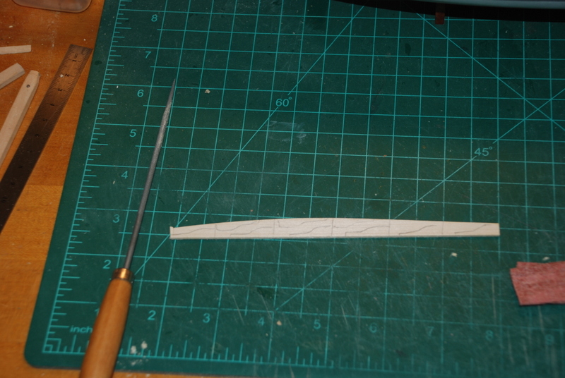
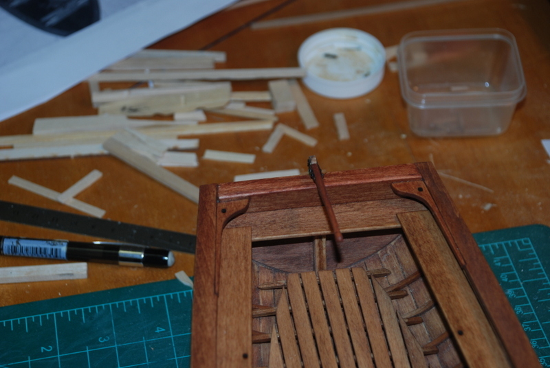
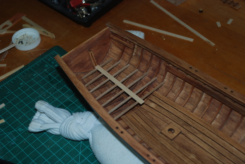
To make the quarter knees, I drew the shape onto some strip wood, which was actually left over laser cut sheet that came in the kit. I cut each one out in the jig saw, then got them to the final shape with a round file and some sand paper. I trimmed the thin ends so they were all the same length. Here is the strip before cutting: And here are the quarter knees before staining. After I stained them, I glued each one in place and here is the result, along with the glued in thole pins, which have not been stained yet:

- 153 replies
-
- 1
-
-
- model shipways
- bounty launch
- (and 1 more)
-
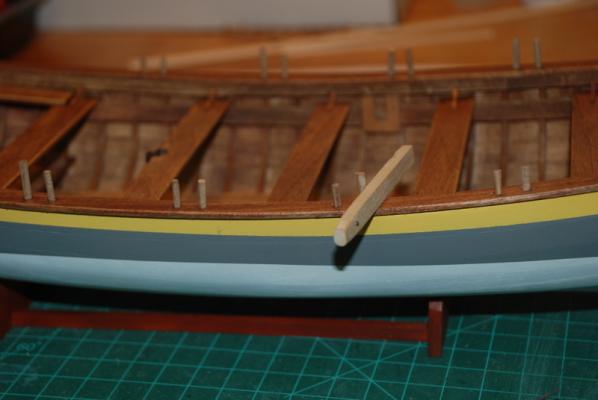
I have been working on the thwart knees and thole pins this week. As you can see in this picture, the supplied dowel in the kit (on the right) is way too small for the size of the pre-drilled holes in the thwarts and other pieces. So, I put some of the left over cherry frames (actually the ones that broke during bending) in the lathe and turned them round with some sand paper, and used these for the thole pins (on the left) in the above picture. I out them all in the holes in the bulwarks, then used a strip of wood that was the correct height to mark them. I took each one out and cut it to the mark, then sanded the top and glued them back into the holes.
-
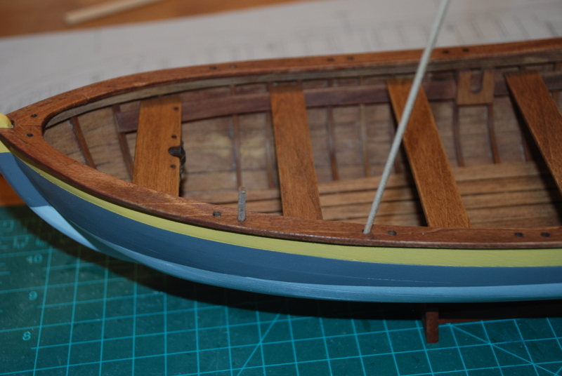
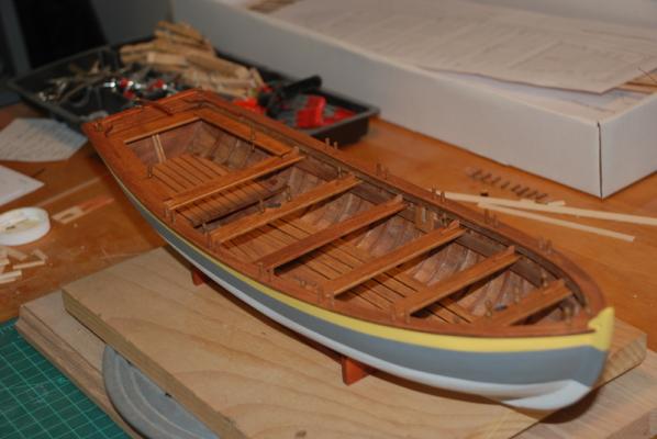
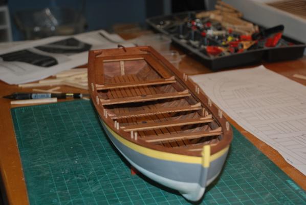
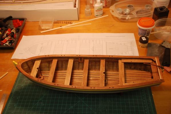
Here are the thwarts in place: I don't know why the edge of the back rest looks so light in these pictures. Here is better picture of the stern which is closer to how it looks for real:

- 153 replies
-
- 2
-
-
- model shipways
- bounty launch
- (and 1 more)
-
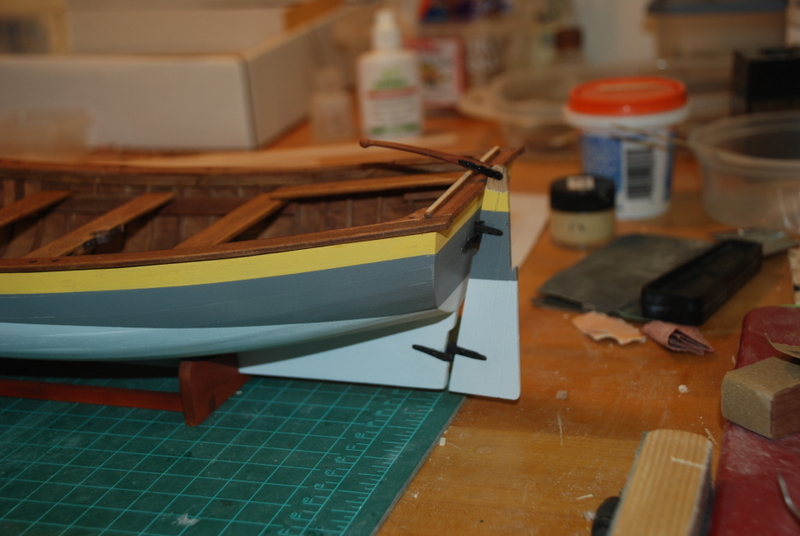
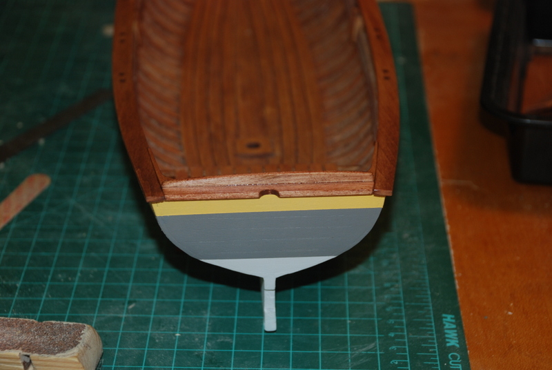
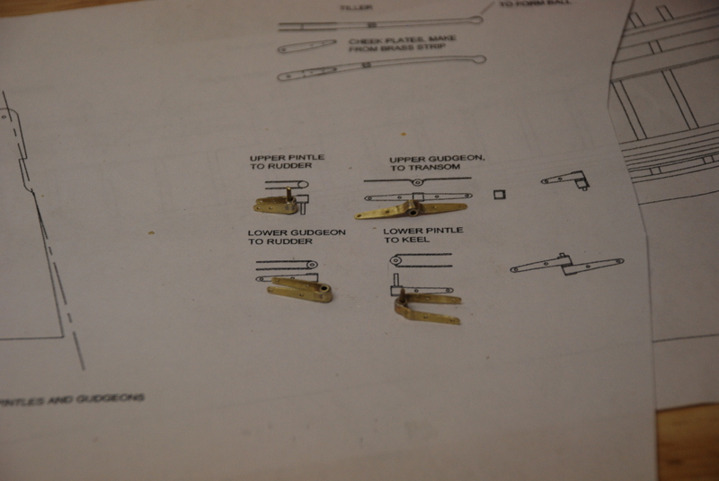
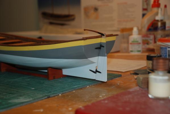
I attached the pintle an gudgeon to the rudder by gluing them in place, then drilling holes into the rudder through their holes and gluing in nails that were mostly just heads. I then stained the tiller and did some touch up paint on the rudder. To attach the rudder to the hull, I put the pintle and gudgeon that are attached to hull on the corresponding rudder parts, then clamped the rudder to the hull as shown here. This let me drill the holes into the hull through those parts and add the nail heads, after gluing them in place. I then attached the tiller by pushing a brass rod through the two tiller brackets and the rudder head. I touched up the paint on the brackets and the hull parts, and here is how it came out:

- 153 replies
-
- 2
-
-
- model shipways
- bounty launch
- (and 1 more)
-
Where Do You Keep Your Working Plans
usedtosail replied to BubbleHead's topic in Modeling tools and Workshop Equipment
I hope you don't get too much saw dust in your dinner. I love that last picture though. -
Looks good Mike. I can't wait to see the finished guitar.
- 170 replies
-
- 1
-
-
- thames barge
- billing boats
- (and 1 more)
-
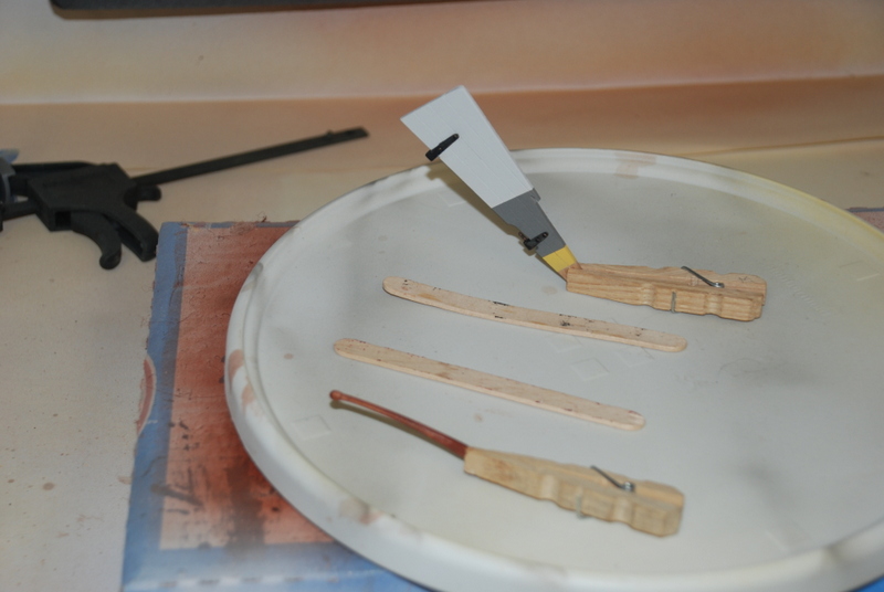
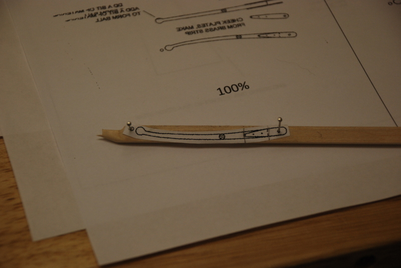
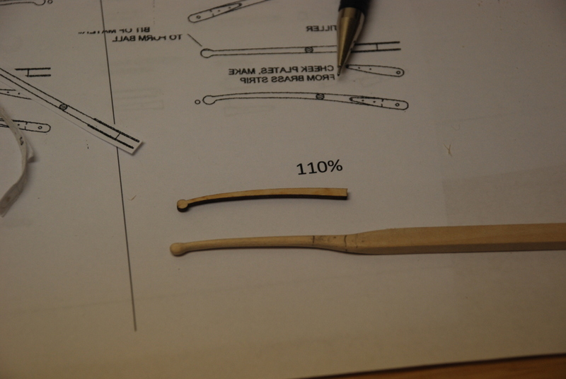
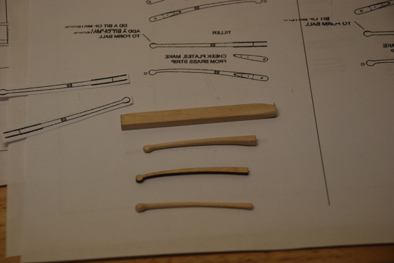
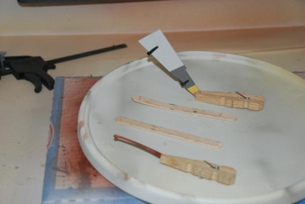
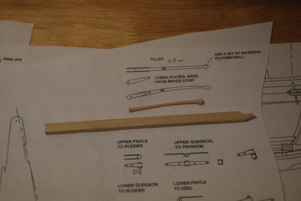
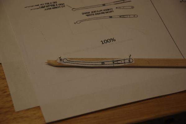
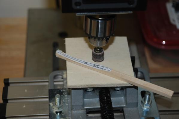
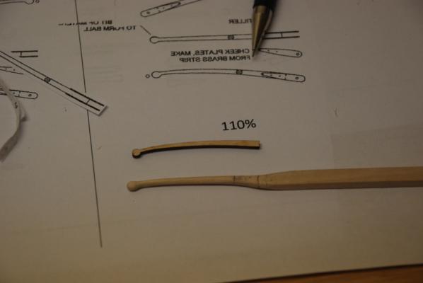
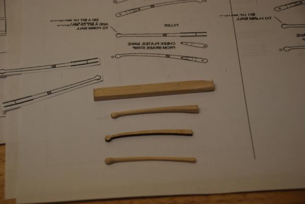
I did not like the supplied tiller with the kit so I decided to try making my own. The first one I made by copying the plans for the tiller and flipping them so I had a template for each side, which I glued to a piece of basswood using a glue stick. Thanks to EdT for his great build logs that inspired me to try his technique. I sanded the wood down to close to the edges of the template using a belt sanded and a Dremel sanding drum in the drill press, then finished up by hand filing and sanding. It came out OK but was too round at the rudder end, but it showed me that this was possible. The second one I did similarly but with a few changes. I found it hard to line up the templates on both sides, so this time I added a small dot besides the tiller end. I also scaled the template up by 5% because I thought the previous teller was a little too small. This time when I glued the templates to the basswood, I drilled a hole through the dot and the tiller bracket pivot hole and used straight pins to line up the templates on both sides. This made this step a lot easier. I also used just the Dremel sanding disk and not the belt sander, which I found gave me more control and avoided taking too much off. I again finished up by hand filing and sanding. I left the rudder end square so the tiller brackets have better attachment points, but rounded the rest of the tiller. Here is the wood strip I started with and the first tiller: Here is the second tiller being made, with the templates being glued to the wood strip: Sanding the rough shape on the drill press with the Dremel sanding drum: Second tiller after hand sanding compared to supplied tiller: New completed tiller, supplied tiller, and first made tiller: After staining the new tiller, I realized it was a bit wider than the rudder, so I sanded the flats down more to make them the same width, then restained it.
- 153 replies
-
- 1
-
-
- model shipways
- bounty launch
- (and 1 more)
-
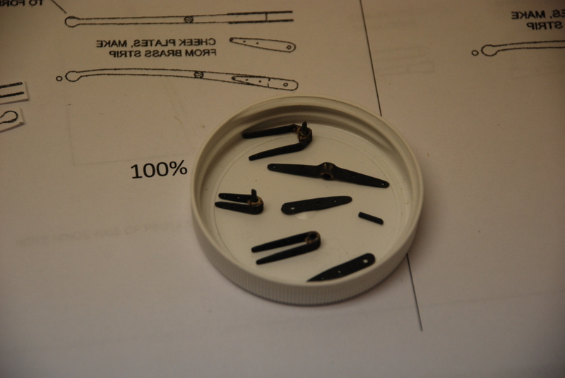
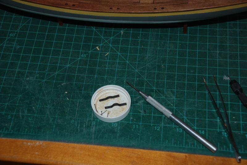
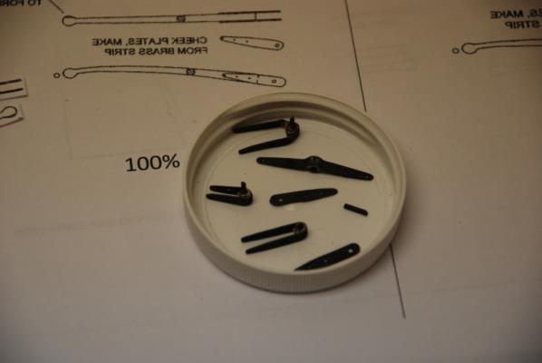
I blackened the rudder hardware this morning and for the most part the pieces came out well. There are a couple of places that are a little bright still, but mostly they are inside. I will touch them up with a little black paint. You can also see the two brackets and pin for the tiller.
-
Nice looking cannon Henry. And have a Happy Birthday.
-
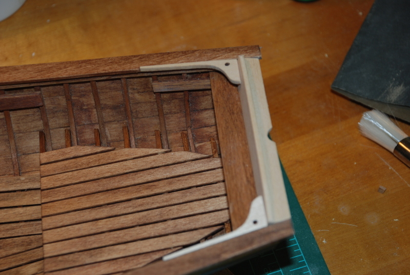
Yeah, Mike, I like working the small stuff if its not too small. As promised here are the pictures of the completed stern. I installed the stern gunwale, back rest and quarter knees at the same time to make sure they all fit nicely. I then masked off the transom so I wouldn't accidentally scratch the paint and sanded the ends of the gunwales flush with the stern gunwale. I then gave everything another coat of stain. Here is the completed section, although since I took this picture I touched up more of the stain to even out the color on the gunwales.

-
I agree, nice job Kimberley. Looks like you learned a lot too.
-
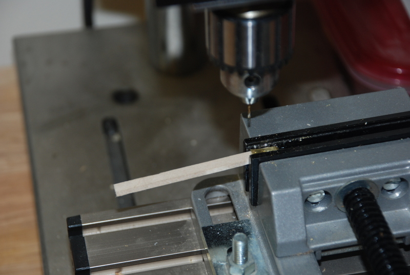
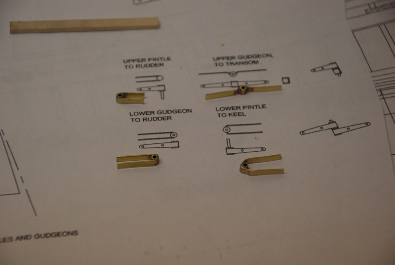
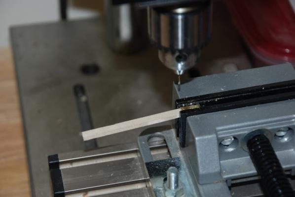
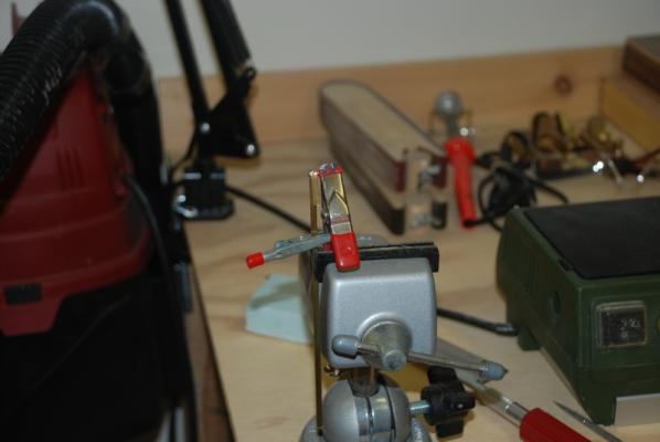
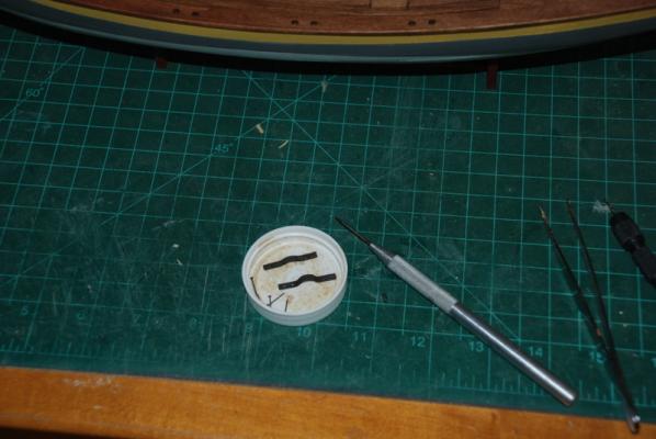
To continue with the pintles and gudgeons, I placed each one around a strip of wood and made indents with an awl where the holes were to be drilled. I then used the drill press to drill the holes, with only about ¼ inch of the drill bit out of the chuck. I did not have any bit wander with this approach, although the brass was a bit dented afterwards. This was easy to correct by squeezing the sides in square jaw pliers. I then used small tin snips and some files to thin down the edges of the parts so they were tapered and rounded on the ends. I finished up with emery paper to clean up the faces of the parts. I cut two lengths of brass rod and super glued them into the two pintles. Here is what they look like now, ready for blackening: I'll have pictures of the stern interior after I clean that area up some tonight. I have glued the back rest, stern gunwale, and quarter knees in, but I need to sand everything flush and touch up the stain.
- 153 replies
-
- 1
-
-
- model shipways
- bounty launch
- (and 1 more)
-
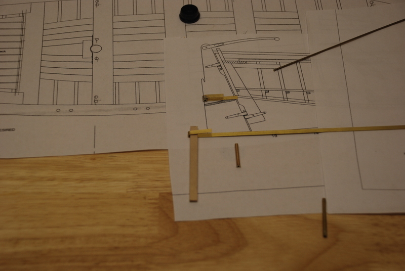
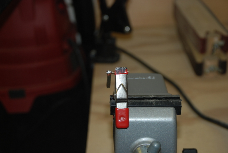
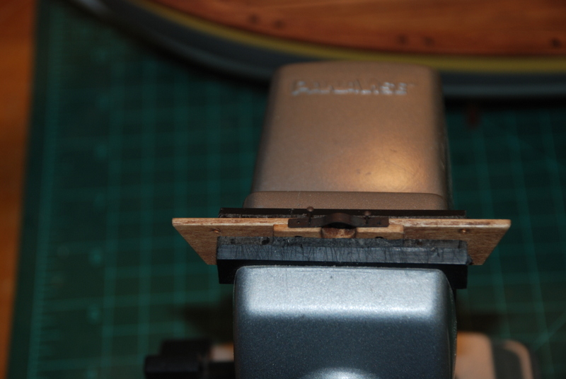
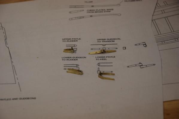
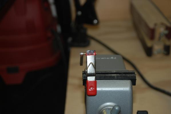
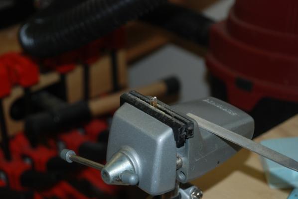
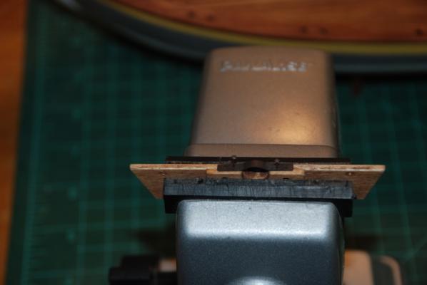
Thanks again Mike. I think the pictures do this model more justice than I deserve. While waiting for the stain to dry on the stern pieces, I started making the pintles and gudgeons for the rudder using the supplied brass strips, some round brass tubing, and some brass rod. I started by bending the brass strip around a piece of wood the same width as the rudder. I then soldered the pieces together using low temp solder. I had to come up with a way to hold everything that wouldn’t melt, which is a problem since the vise jaws and many of my clamps are plastic. Here is what I came up with, that worked very well. The tubing is in the large clamp. The alligator clip kept the brass strip from sliding off the tube when I held the soldering iron to it. Here is what it looked like after soldering. The brass heated up quickly and the solder flowed into the joint nicely. After the strip and tubing cooled down, I cut the part from the brass strip with tin snips, and cut off the excess brass tubing with a razor saw. I then cleaned up the solder with some files and some abrasive paper. I also used a file to make the tubing flush with the strip. I made the two parts for the keel and transom the same way, but for the keel part I used a wider piece of wood to bend the strip around. For the transom piece, I bent it around the wood to solder it, then straightened the brass strip out, since this piece needs to sit flush on the transom. Here is how they look at the end of this step: More to come...

-
Drill bits work well for wrapping wire around if you don't have small enough dowels.
- 234 replies
-
- 2
-
-
- 18th century longboat
- model shipways
- (and 1 more)
-
Let me add my congratulations to the rest. The boat looks fantastic
- 234 replies
-
- 1
-
-
- 18th century longboat
- model shipways
- (and 1 more)
-
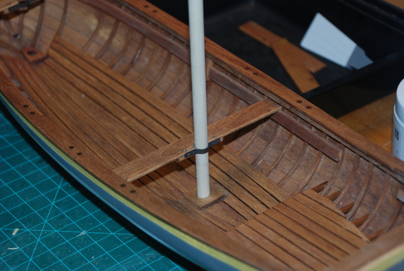
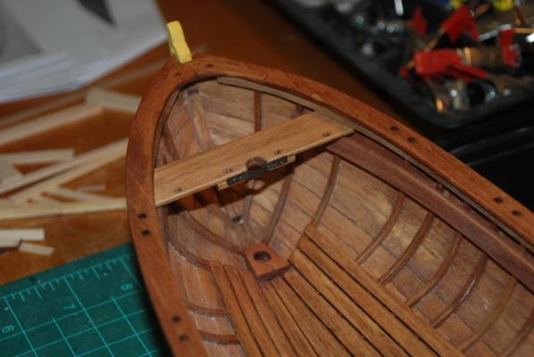
Yesterday I made the mast partners from the brass strip supplied in the kit. I bent the brass around the mast dowels while I had them in the cut outs of the two mast thwarts, then finished up shaping them with some flat pliers. I used the awl shown in the first picture to dimple the brass for the nail holes, then drilled the holes in the drill press. I then filed and sanded the brass and cut them to length. I soaked them in vinegar, rinsed them in water, then soaked them in Blacken It solution for about 10 minutes to blacken them. I used brass nails that I had from a previous build that were already blackened. These are a little smaller than the supplied nails, which looked more like steel than brass. I used the partners as templates to drill holes for the nails in the edge of the thwarts. I drilled these about 1/2 way the length of the nails. I then used a small hammer and a piece of dowel to set the nails into the thwarts, which held the partners very nicely, so I did not have to use any glue. Here is the fore mast partner: Here is the main mast partner with the main mast dowel temporarily in place:
- 153 replies
-
- 1
-
-
- model shipways
- bounty launch
- (and 1 more)
-
Wow, they actually open and close. That is impressive.
-
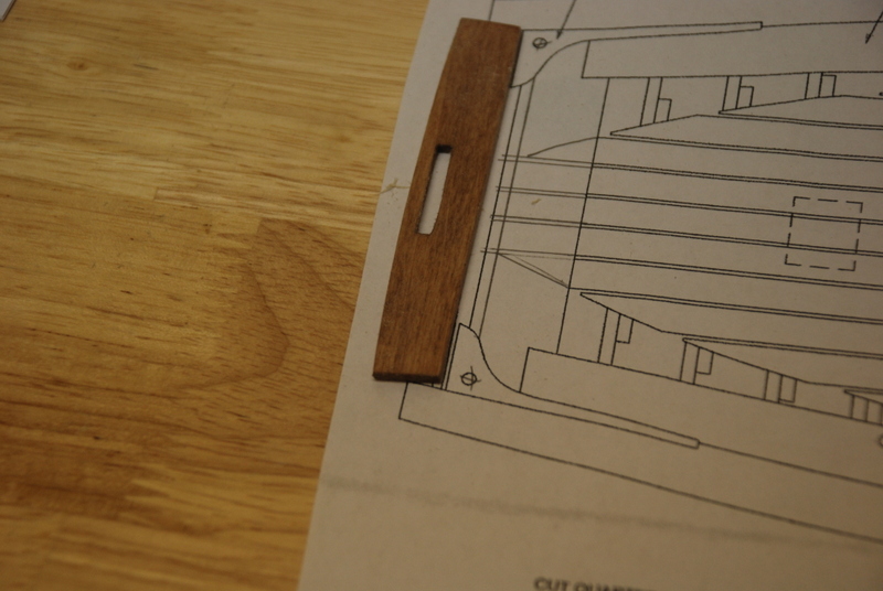
Thanks Mike and Pete. I appreciate the comments. I am a little disappointed with some of the laser cut pieces that Model Expo supplied with this kit. I have found a number of pieces that were either just too small or just big enough to fit before any sanding. I would rather they made the pieces slightly oversize so that they could be sanded to fit. Here is the latest piece I had trouble with, the back rest. At first I was going to eliminate it as others have done, but I think it looks good, so I want to include it. As you can see in this picture, the supplied piece is smaller than the plans: So, I remade the back rest from one of the thwarts that I had to remake because it was too small. I added more to the sides and sanded it to fit. I did not add the cut out in the new back rest. The quarter knees were also too short and since there is a notch in the gunwales for them, I could not just install them further back. So, I made the stern gunwale wider which moved the back rest more forward so the quarter knees would fit after sanding them to the angle of the back rest. Here is how these pieces all came out. They are just dry fit as I still have to stain them. You can see that even the width of the quarter knees is too small where they fit in the notches, so I am going to have to sand the gunwales down at those spots. I would rather have the quarter knees too wide and sand them to fit the gunwales. It is not like we are talking about a lot of excess wood here, just a few millimeters on each piece that would made a big difference.


- 153 replies
-
- 1
-
-
- model shipways
- bounty launch
- (and 1 more)
-
Have a great day on your Birthday, Mike. I love the color of that guitar, too.
-
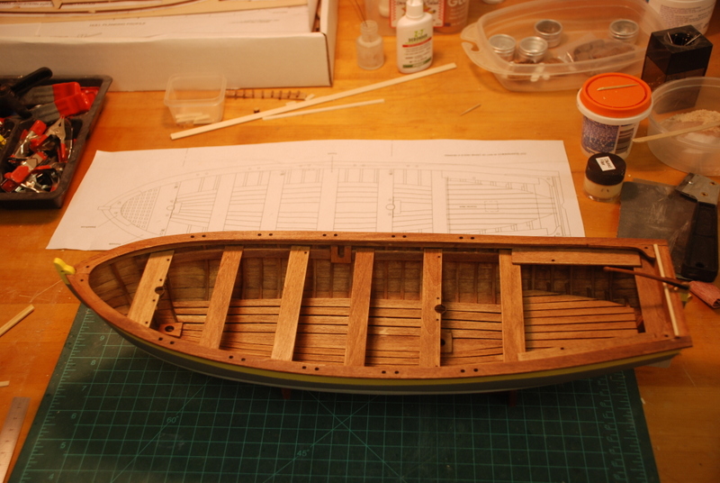
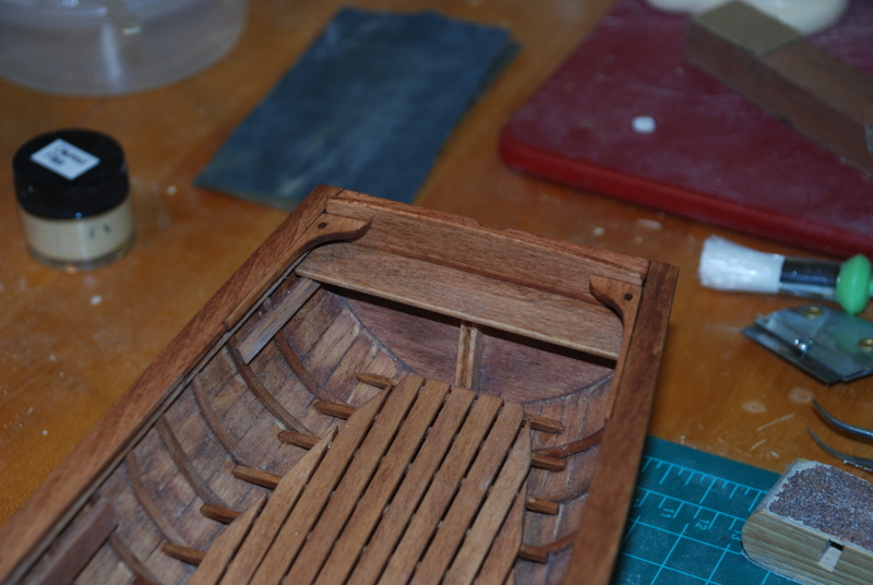
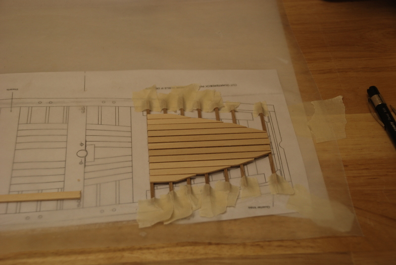
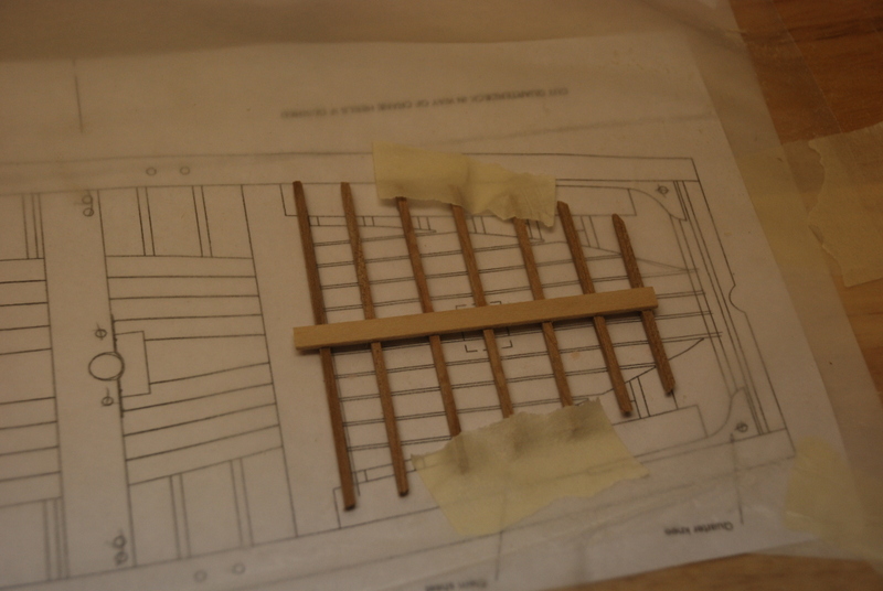
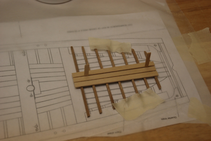
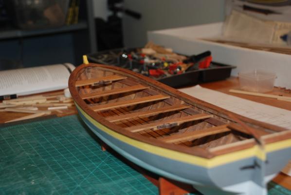
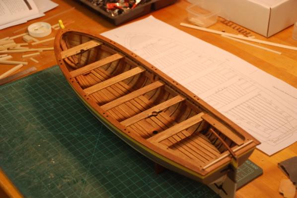
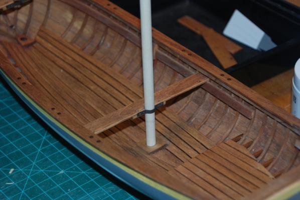
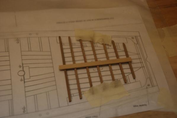
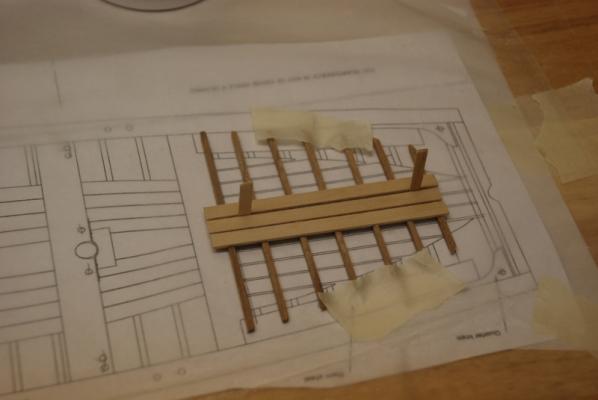
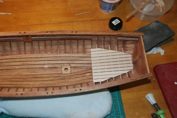
Here's the story with the quarter deck. My first attempt was to make the quarter deck on the plans, then fit it into the hull. I left the frames long so I could cut them down to fit. This actually worked fine as I was able to trim the frames back a little at a time and get the deck to fit into the hull. I had to trim off the stern frame and some of the planking to get it to fit far enough into the hull, but that was not a problem and I just glued a new frame to the back when the fitting was complete. What I didn't like was that the quarter deck frames did not sit flush to the hull frames, so the deck was just sort of floating in the hull. This didn't seem right to me, so I decided to remake it. I used alcohol to loosen the glue and was able to salvage all of the planks and most of the frames. This time I fit each frame into the hull before the planks went on, making sure they were flush up against a hull frame and the planks would make contact with all the frames. When they were all in position, I glued the center plank to the frames and readjusted the frames back up against the hull frames before the glue set up. I let this dry a few minutes, then carefully took it out and transferred it to the plans. I then glued the rest of the planks onto these frames, using thin strips of wood to keep the distance between the planks more consistent, which is something I didn't do on the first attempt and it showed. When this dried, I trimmed the excess off some of the planks and test fit it back into the hull. I was much happier with this version. Now it just needs to be sanded and stained, and it will be ready to be installed.


- 153 replies
-
- 2
-
-
- model shipways
- bounty launch
- (and 1 more)
-
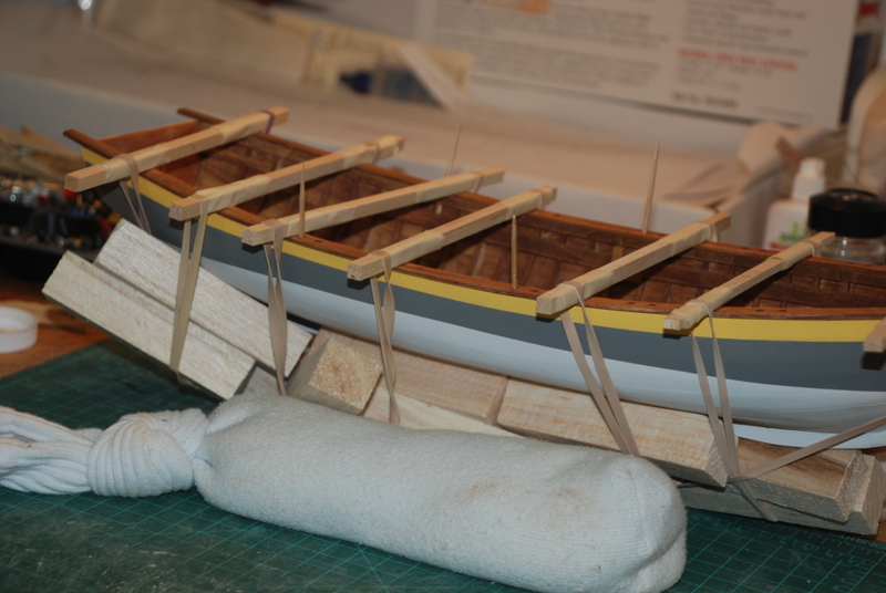
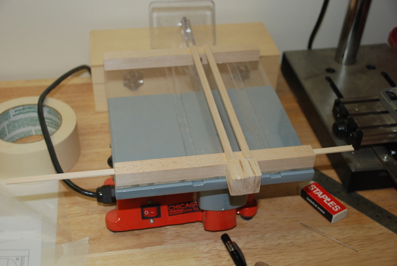
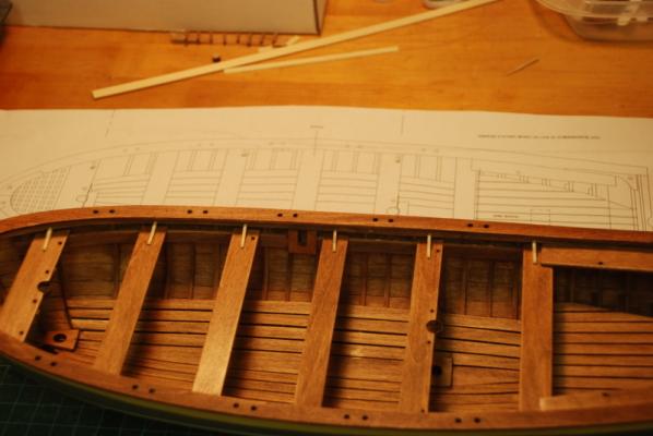
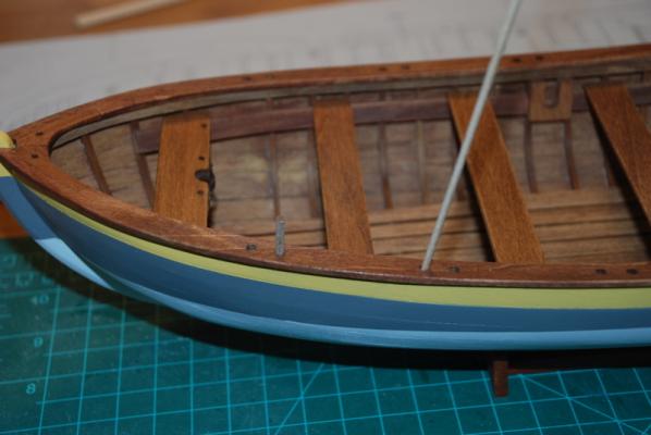
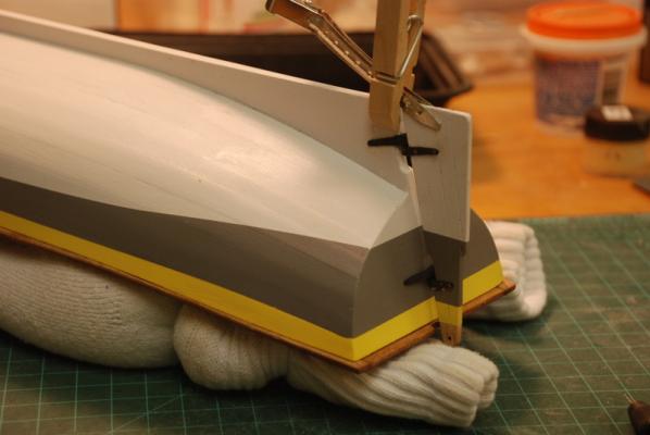
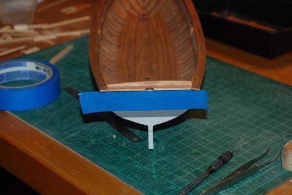
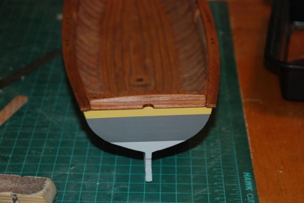
Here's the progress over the last week. I glued the gunwales to the hull, using clamps made from wood strips wrapped in masking tape where they contacted the gunwales and rubber bands. These worked pretty well, but there were a few spots where the gunwales did not bend enough to make contact with the hull. I added balsa wood blocks under the rubber bands to give the clamps more pressure and this helped pull the gunwales down to the hull. The next day I removed the clamps and addressed the couple of areas that were not in contact. I used the glue injector shown in the next picture to inject glue under the gunwale in the spots that didn't make contact, then re-clamped these areas. The injector is just a large syringe I got in a kit to fill ink jet printer cartridges and it works great with wood glue. The tip will plug up right at the end, but a piece of wire in the nozzle clears it right up. This step brought the gunwales into place. I made up the strip of wood to fit between the two gunwales at the stern, using some basswood sheet. I cut it using my cheap table saw from Harbor Freight. This saw is nothing like the Jim Byrnes saw, which I hope to have someday, but for now it works fine with this sort of job. This saw is very under powered, so you have to use it appropriately, but with care it works OK on soft woods like basswood. I bought a slitting blade for it on eBay, which make nice thin cuts. I also made the Plexiglas fence shown in the picture, since the cheap saw came with no fence. It acts as a zero clearance insert, and makes the saw usable. The second picture shows a sled I also made for this table saw, which comes in handy for cutting longer pieces. The next post will discuss how I made (and remade) the quarter deck.

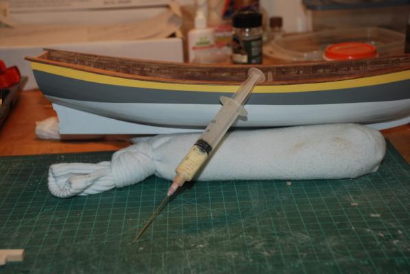
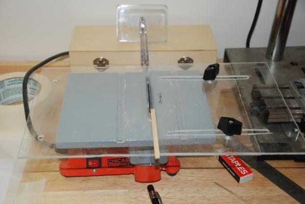
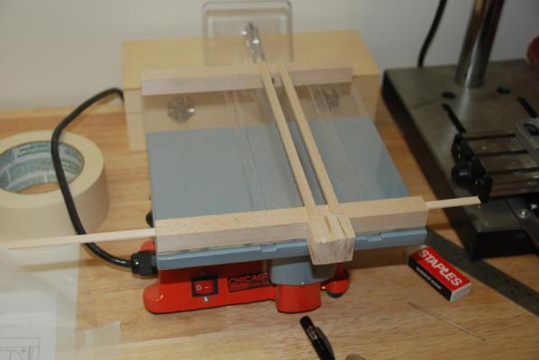
- 153 replies
-
- 1
-
-
- model shipways
- bounty launch
- (and 1 more)