.JPG.ca33079f5815b861e67b9c2cccd37982.JPG)

Blue Ensign
-
Posts
4,572 -
Joined
-
Last visited
Content Type
Profiles
Forums
Gallery
Events
Everything posted by Blue Ensign
-
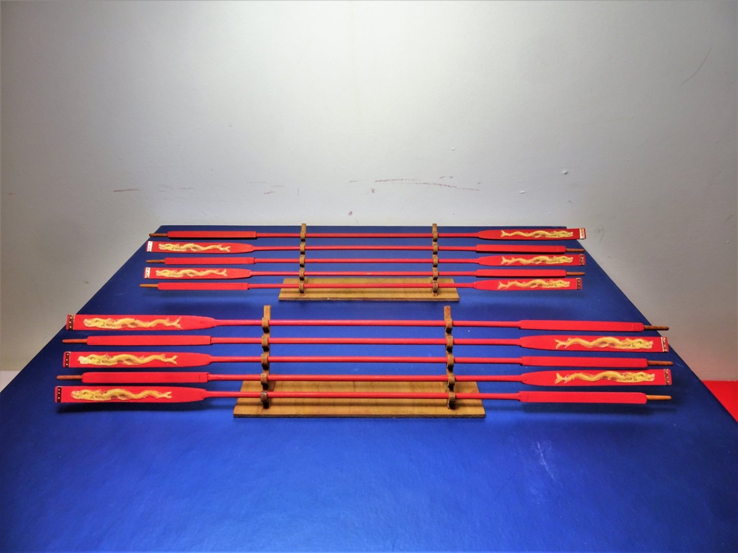
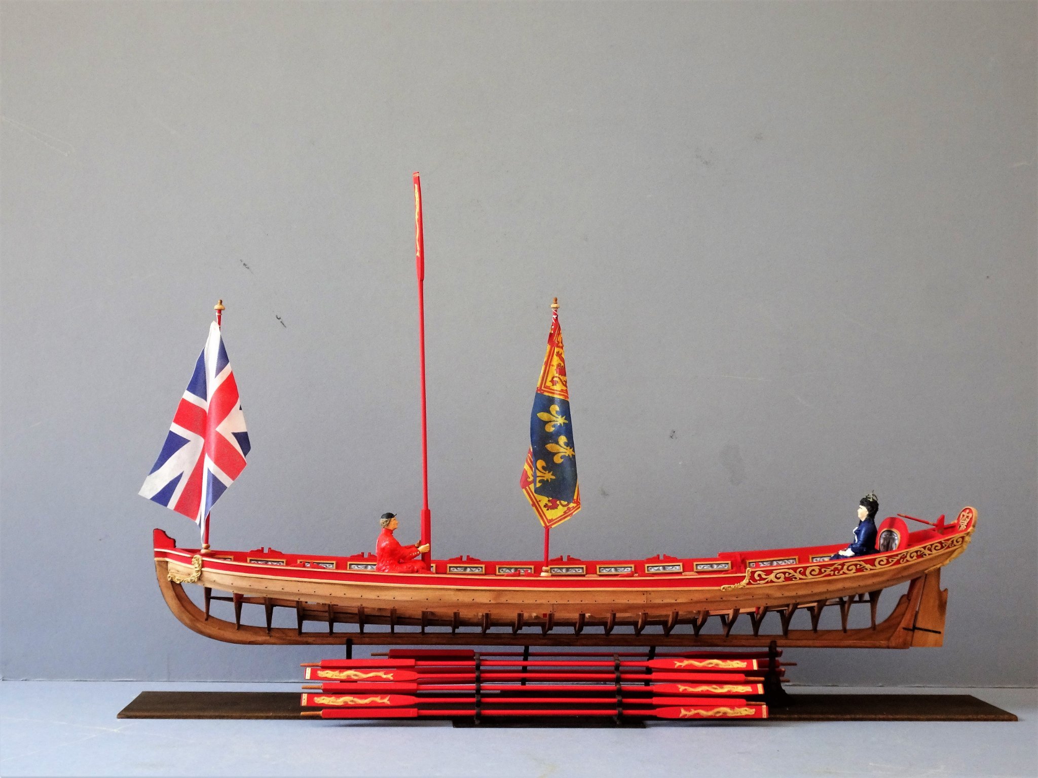
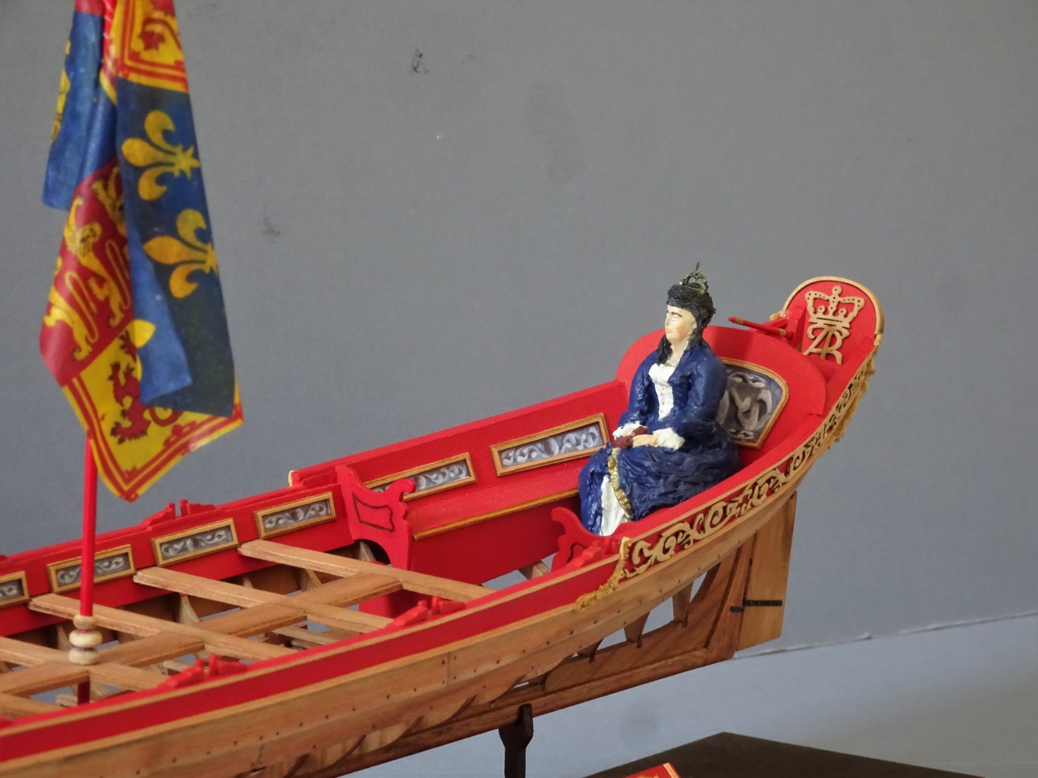
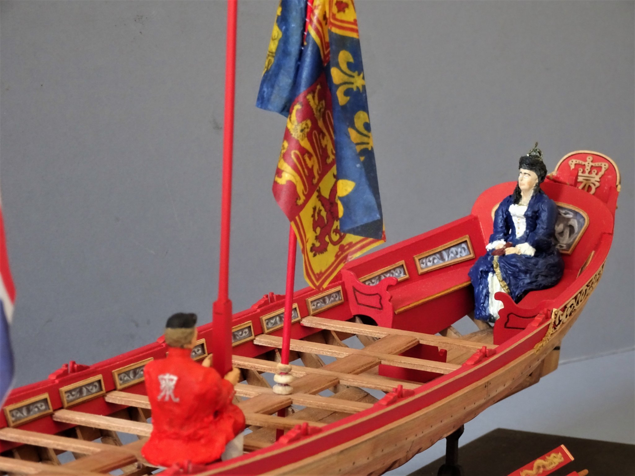
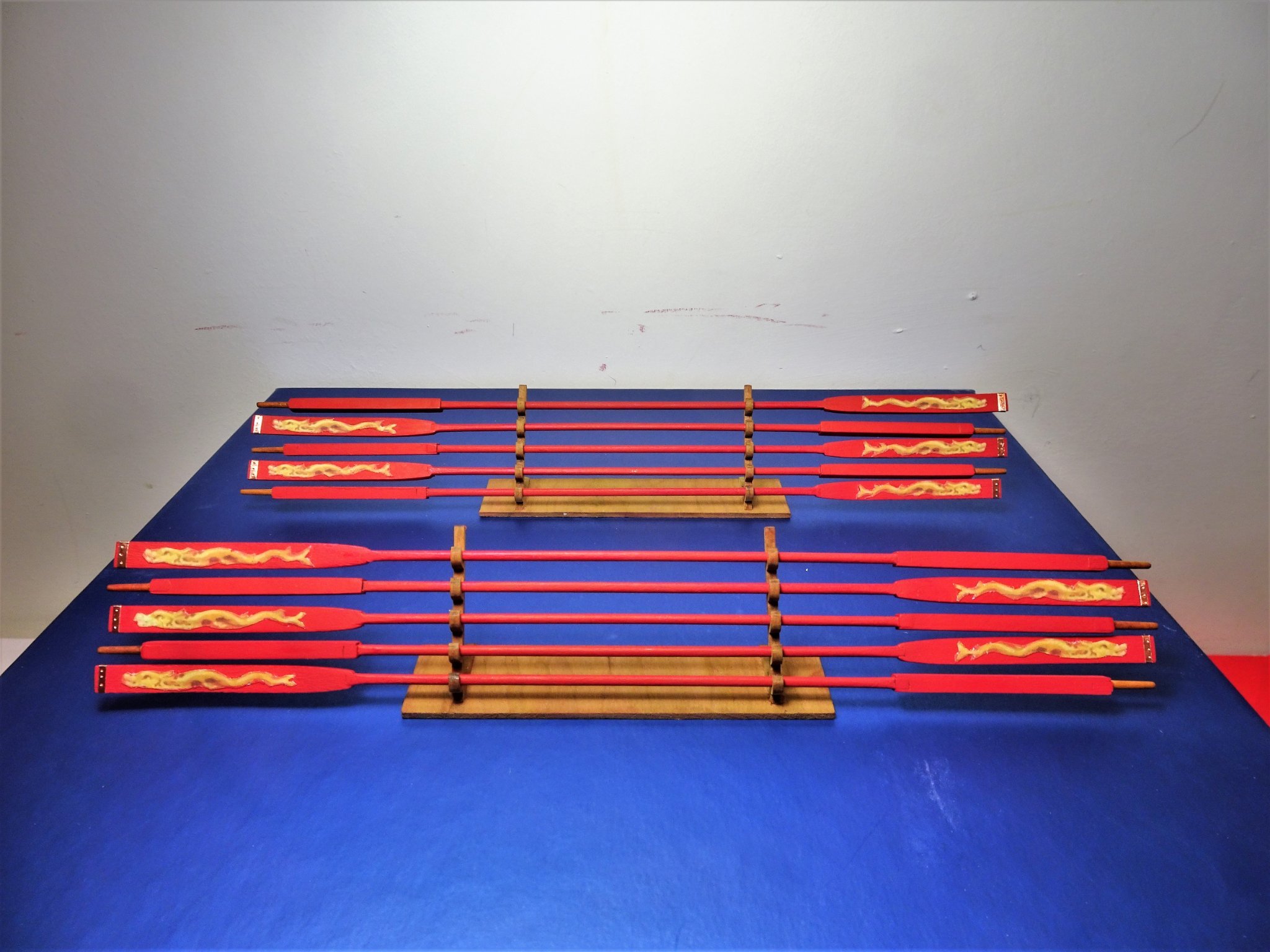
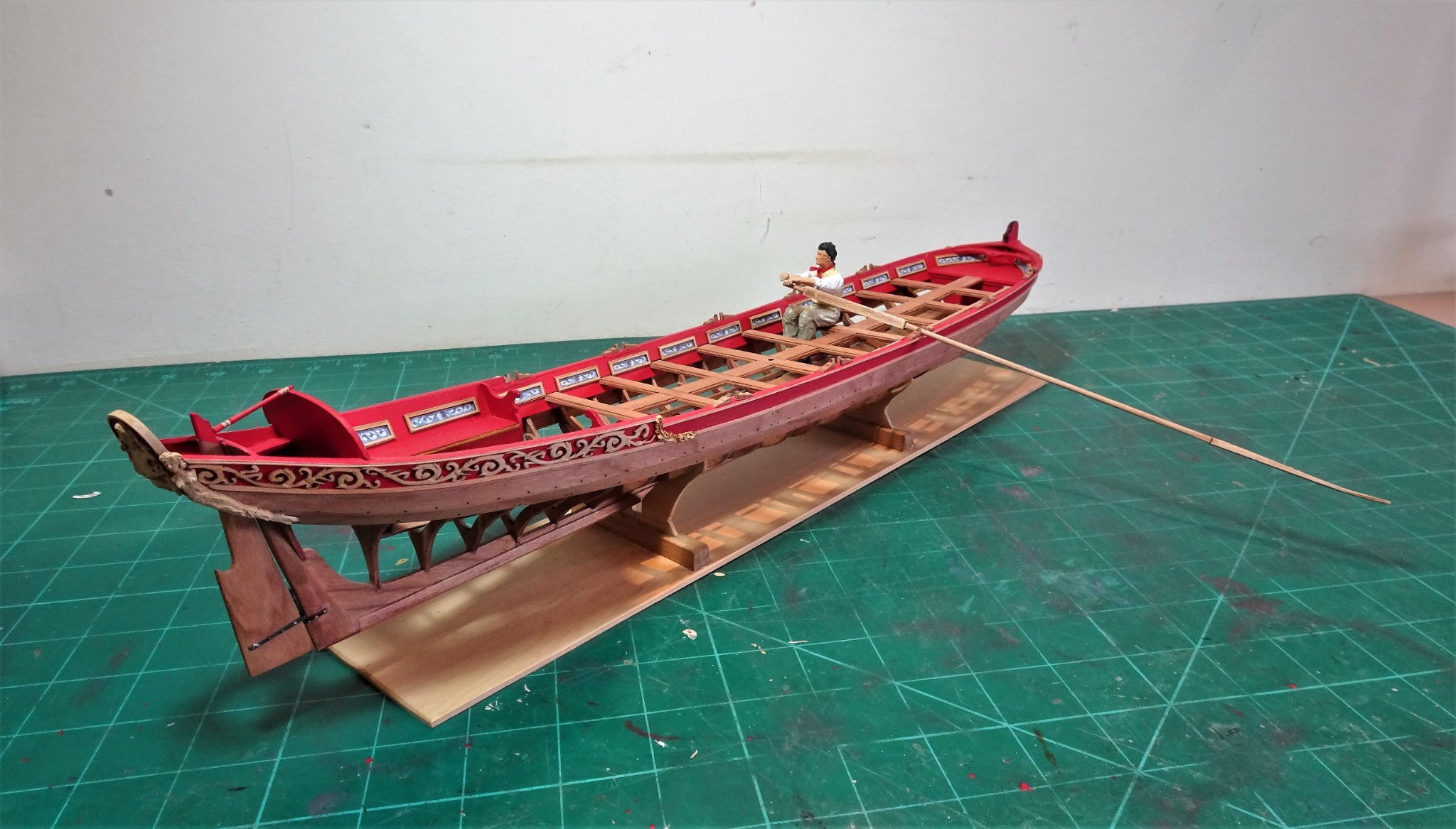
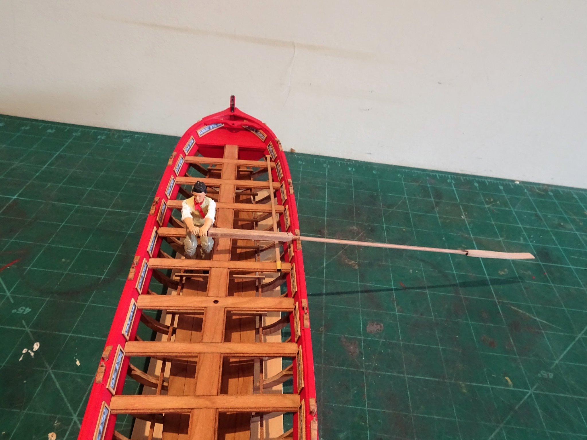
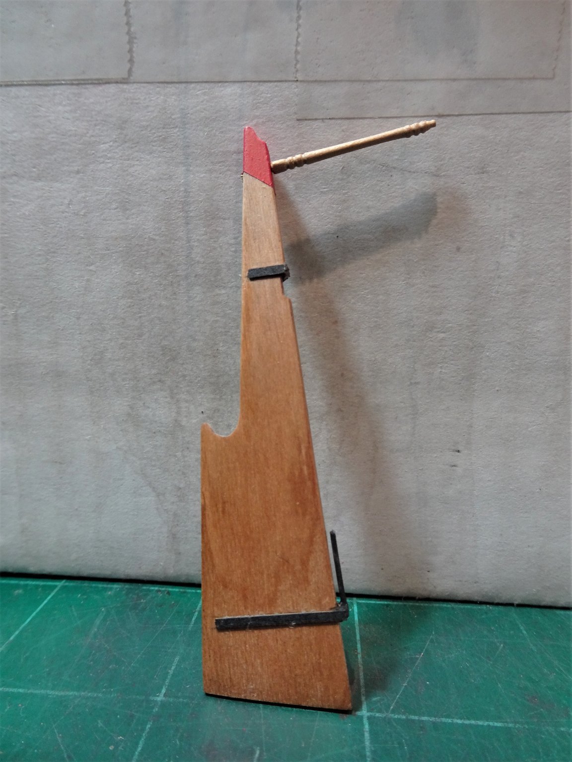
 Post Forty-eight Completion I decided I would keep the display simple using the keel support stands supplied in the kit. 2972(2) These were glued to a strip of ⅛” Castello Boxwood 3” x 24” left over from my Cheerful Build. 2973(2) This was dyed Jacobean Dark Oak. I normally baulk at dyeing Boxwood but the piece was handy and in its natural colour was too pale for the scheme. 3009(2) For space saving I have gone with the oar racks arrangement and the whole model fits in a space of 5½” wide by 24” long by 10” high. Not sure whether I will get an acrylic cover to fit over the model at this stage as it is relatively easy to dust. 3007 2975 2983(2) I have re-visited the Oarsman and adjusted his dress. 3012 I recall that Jason (Beef Wellington) suggested:- Think if you can get a little more 'flounce' to the bottom of the jacket to differentiate from the breeches they'll look great. I took his advice and I think the figure does indeed look better. It was also necessary to tweak the arm/hands position to accommodate the loom of the oar. 3014(2) 3030(2) 3020 3021 Not sure I can face the making of another nine oarsmen, but I think I will keep the one with the display. 3003(2) 2995(2) 2998(2) As always there are areas I feel I could have done better but overall I am pleased with the result and have something very nice to add to my collection. Thoughts about the kit This Royal Barge offering from Syren is a very fine thing indeed. An interesting and rather unique subject at a scale that allows for clear detail. This is a kit with many pre spiled laser cut parts, but it doesn’t feel like a kit, and any thoughts of a simple assembly job should be dismissed. Chuck has produced a design that allows the modeller to experience a futtock and frame assembly and offers an introduction to carving decoration. Great care and thought is required throughout and the end result is a model that clearly echoes the splendid admiralty style models displayed partly in-frame. I have thoroughly enjoyed this build and the challenges presented, and have no hesitation in commending this kit to the membership. Thank you, Chuck, for five months of concentration, joy, and a little frustration. B.E 26/07/21
.thumb.JPG.1bc305918f2c49f2ee54773459a1137a.JPG)
.thumb.JPG.be91d5141f9ba0dac33ab3d739913c4d.JPG)
.thumb.JPG.8f3b9314ce09d08afb34e10ece6c8b56.JPG)
.thumb.JPG.a0936edb9a07c5749f025818933d8d8a.JPG)
.thumb.JPG.fff6fefce9cffd10a3bebe48100830d9.JPG)
.thumb.JPG.d918c8c56b1cfa51851ec793b2965432.JPG)
.thumb.JPG.6bcdba6b56d703b4af5149b2291f9acb.JPG)

.thumb.JPG.d170f6fec79629a18a8bbe7dee2937b0.JPG)
.thumb.JPG.1721cdd2af5396ab0d8d77c4560002bb.JPG)


.thumb.JPG.a1e4779900a12e3d3c798251fb31fce4.JPG)
- 185 replies
-
- 25
-

-

-
- queen anne barge
- Syren Ship Model Company
- (and 1 more)
-
Thank you, Bob, Grant, Glenn, and Derek, your continued support is much appreciated, as are those who visit and 'like' @ Derek, the beauty of Modelspan flags is that you can print off as many as you like and tweak them to size. If you mess one up there's always another. 🙂 B.E.
-
Just read thro' your log Eric, and what a journey you have been on, and what an excellent result. The model has great presence and I love the natural finish you have achieved. The display is spot on and the figures are a great addition to the overall effect. Love the bow shot with your first figure onboard. Very well done👍 B.E.
-
Congratulations Derek on completing a very fine build. Those who follow on with this kit will derive great benefit from your log and shared experience. Well done. B.E.
- 725 replies
-
- 3
-
-

-
- vanguard models
- speedy
- (and 1 more)
-
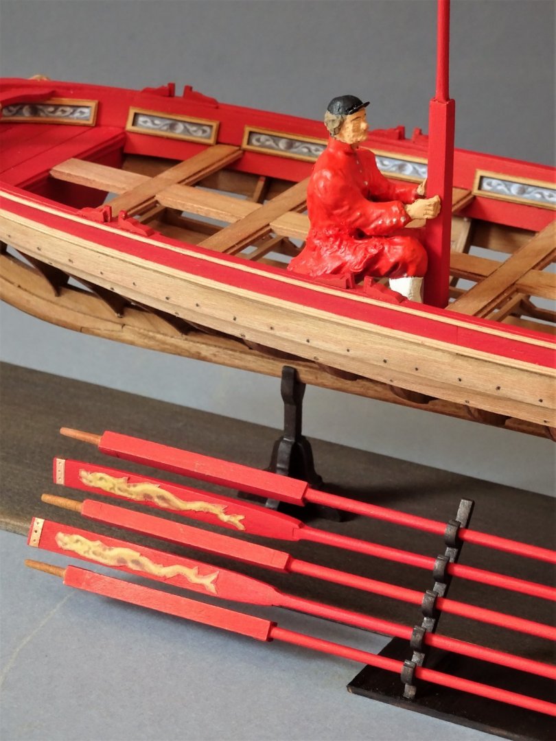
Thank you Bruce, nearly there now. 🙂 Post Forty-seven Dressing the oars. The kit provides a stylised Dolphin design to decorate the face of the oar blades. These are printed on paper and require close cutting before gluing to the blades. I started with a No11 scalpel blade, but found that small pointed scissors proved a better means of cutting without tearing. Even so it proved quite a time consuming business. I used 6mm Tamiya tape to ensure an equal placing distance from the blade tip. The designs are ‘handed’ for port and starboard oars. Once applied using dilute pva, the edges were painted around, and a coat of w-o-p applied to the design. The final act is to add thin strips around the tip of the blade to represent a binding used to prevent the blade tip splitting. I understand that Leather, tin, or perhaps copper strips were used for this purpose. I decided to use copper for no other reason than I liked it but this is a Royal Barge and one can imagine the sunlight flashing off the blade tips as the oars moved with the stroke. 2952 2953(2) 2956 All work is now completed on this build which is not the same as finished. There is a stand to prepare, and some faffing and fussing with the model before the final build photos are presented. B.E. 24/07/21
.thumb.JPG.3c085880274aeb2d90acf1b060985d9c.JPG)

- 185 replies
-
- 19
-
-
-
- queen anne barge
- Syren Ship Model Company
- (and 1 more)
-
A fine model and dio Alan, and a fitting tribute to this iconic cruiser. Did you know that C.S. Forester dedicated his book The Ship to the officers and crew of HMS Penelope. I have a special interest in this ship as my uncle went down with her. As an ERA and with the ship closed up for action he had little chance of escape. He had transferred from her sister ship Aurora in December 43 after she was seriously damaged during an air attack. Such are the fortunes of war. B.E.
-
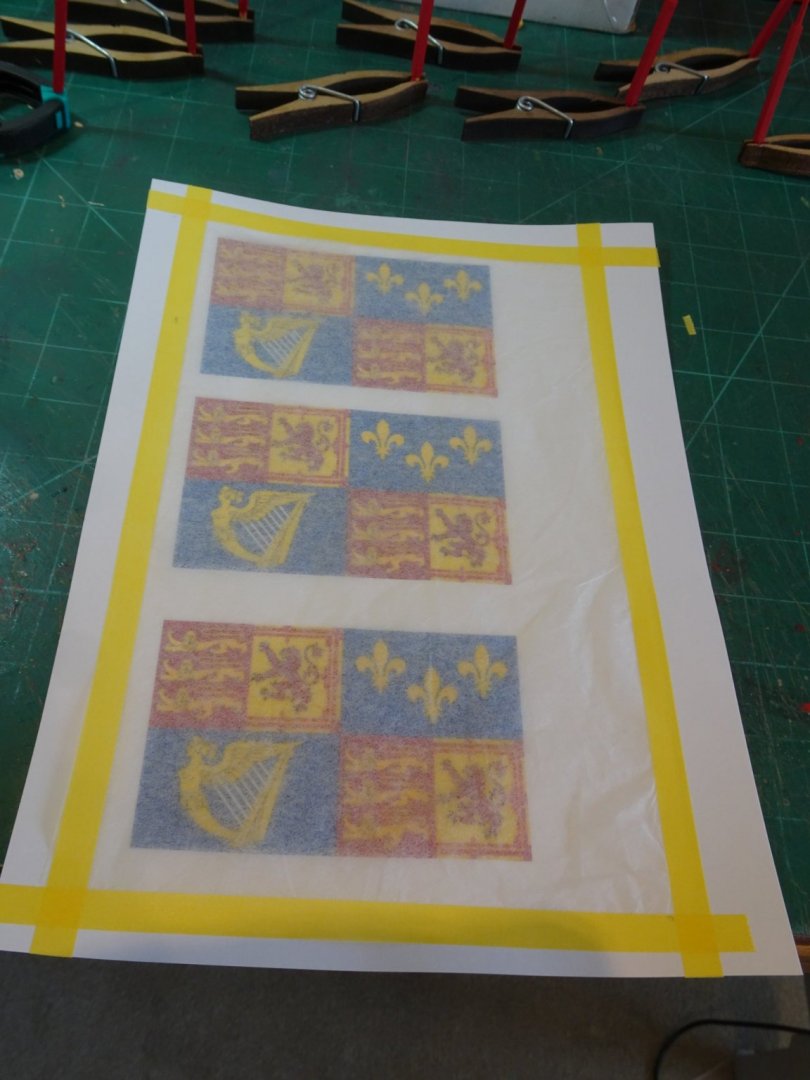
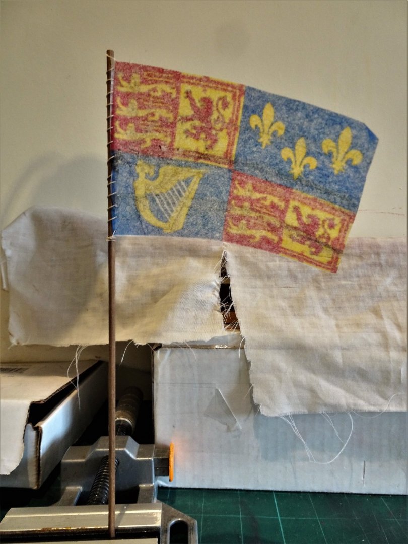
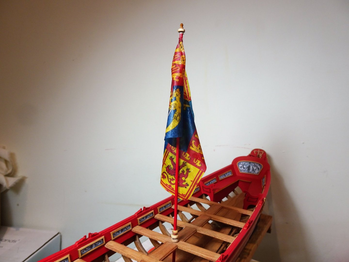
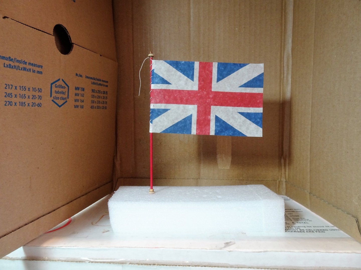
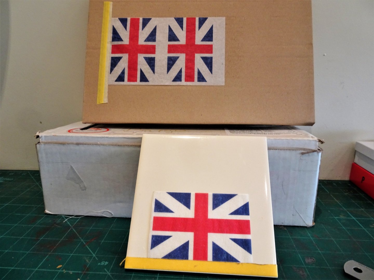
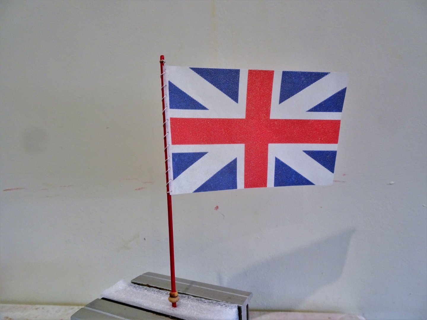
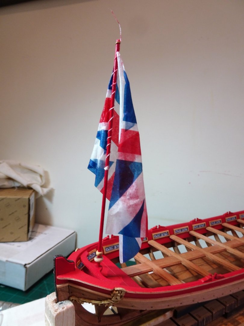
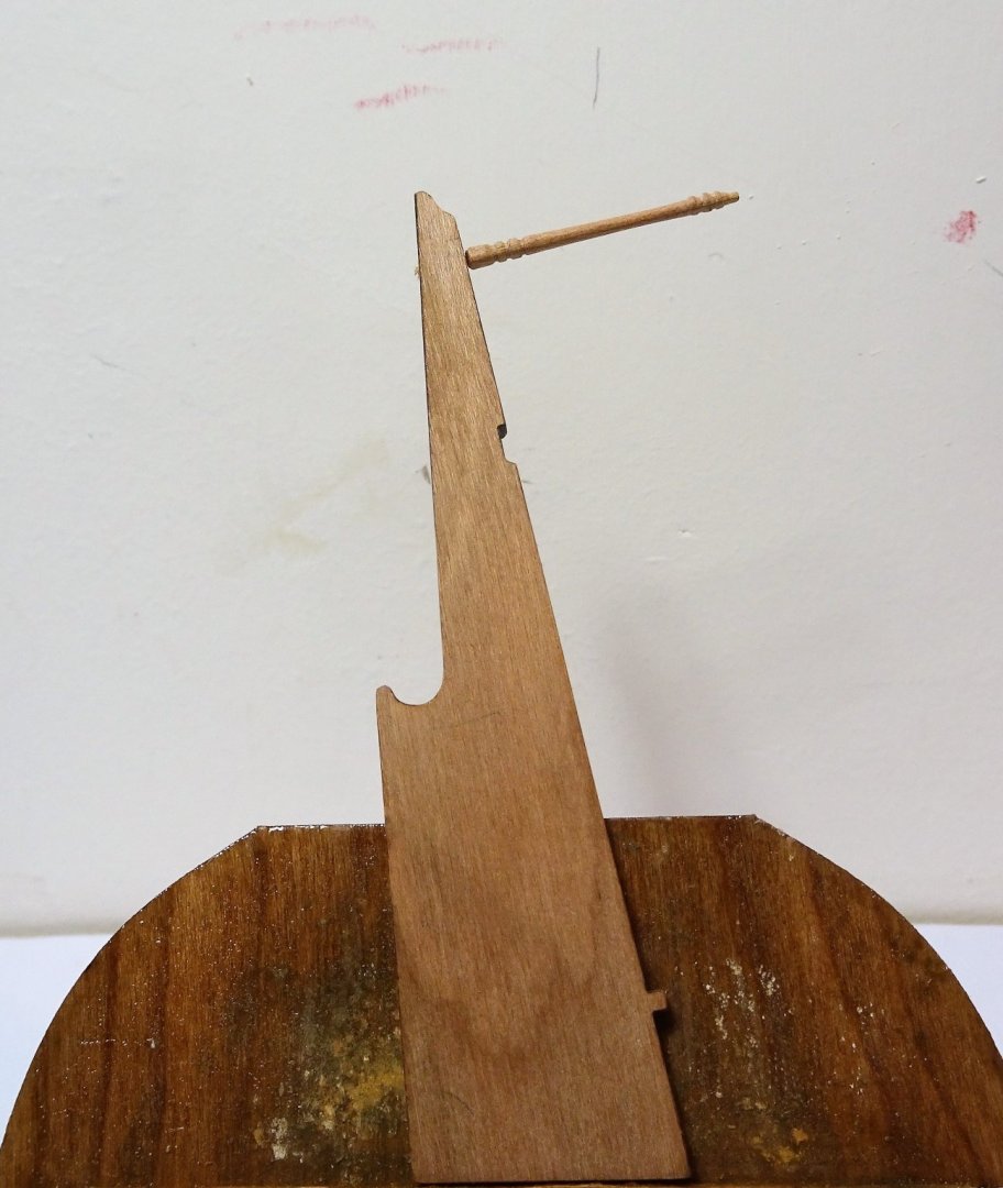
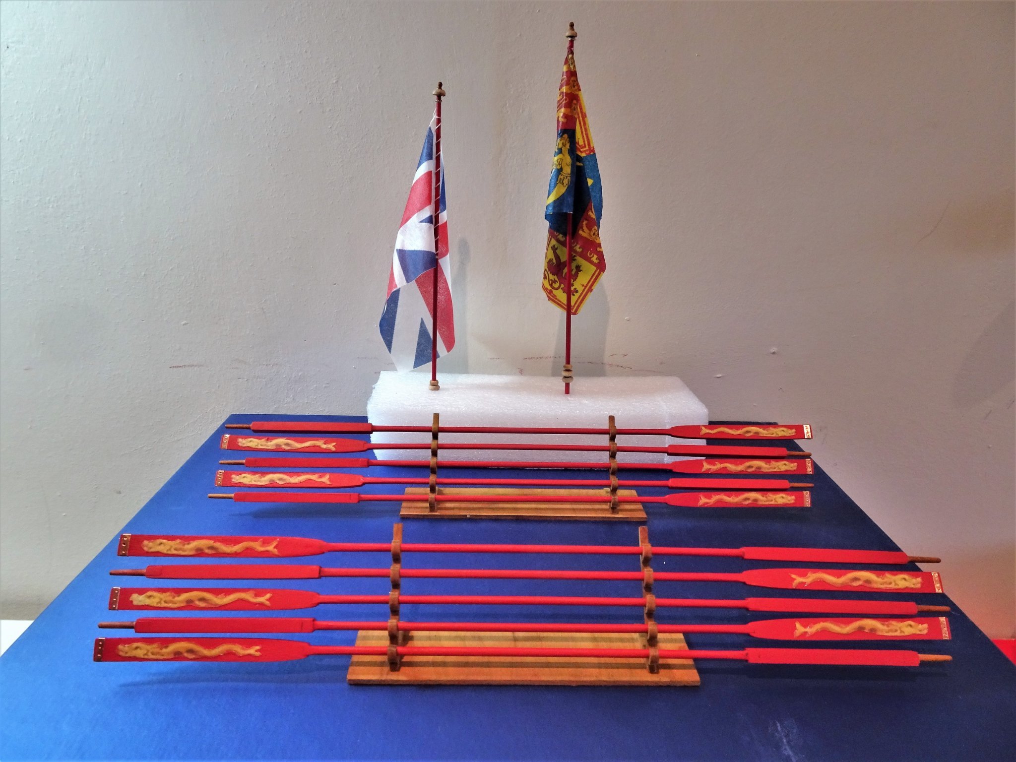
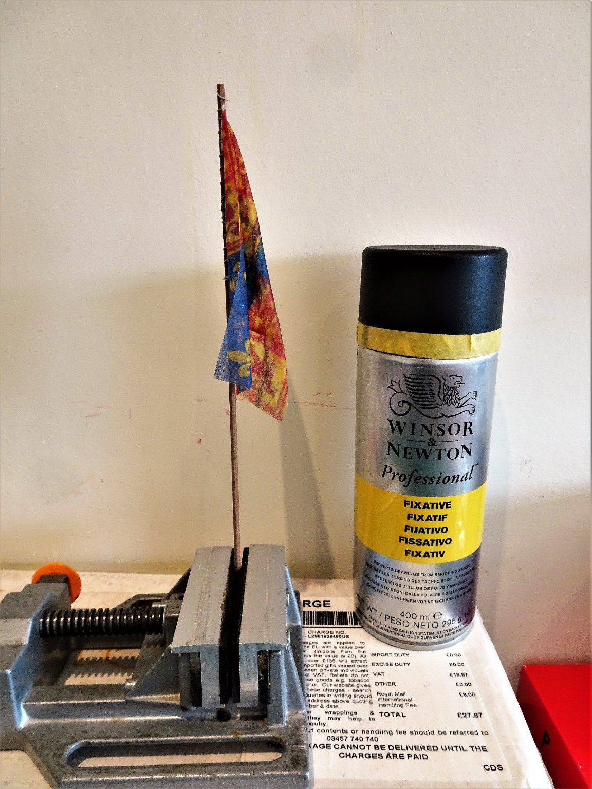
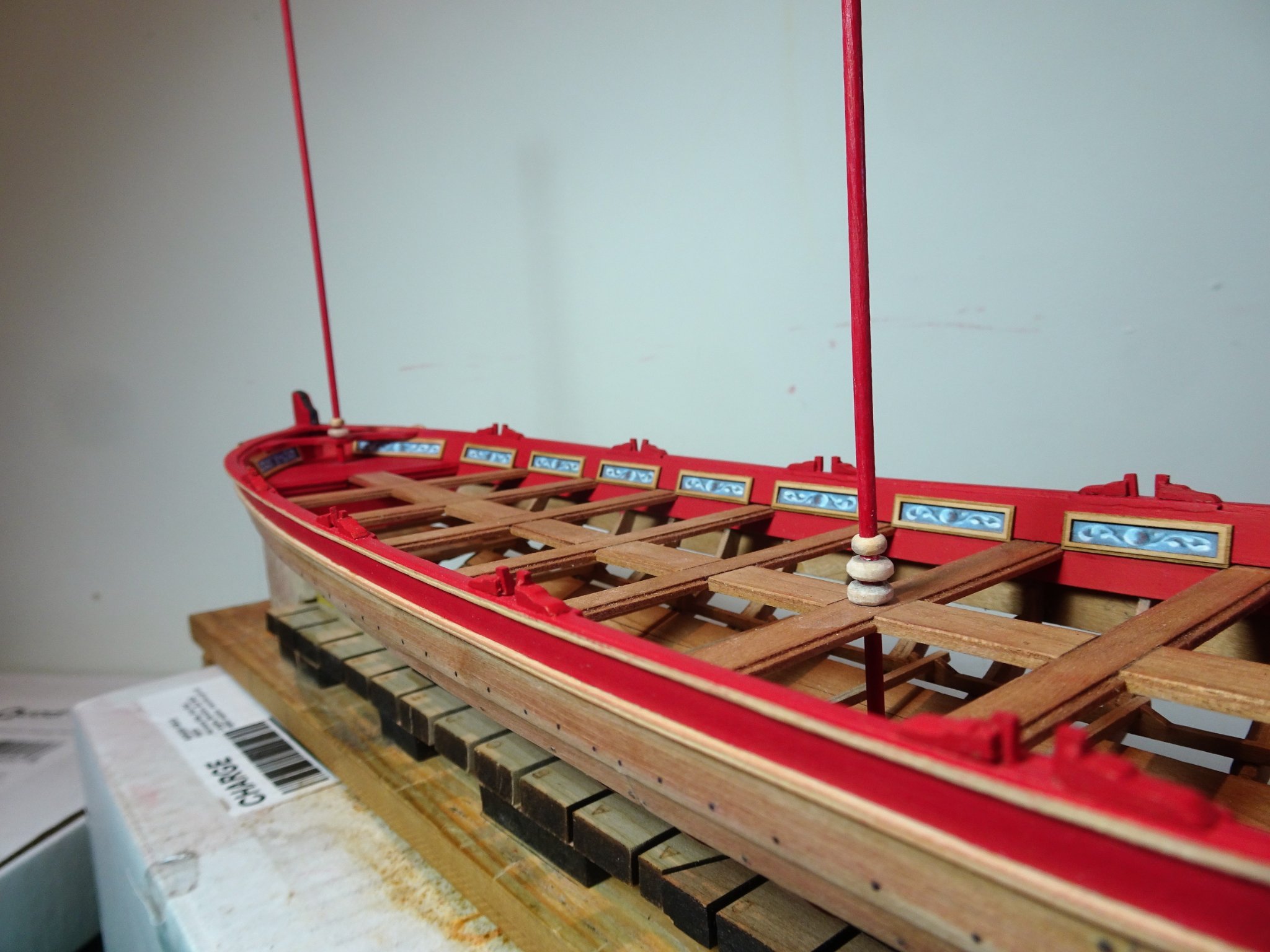
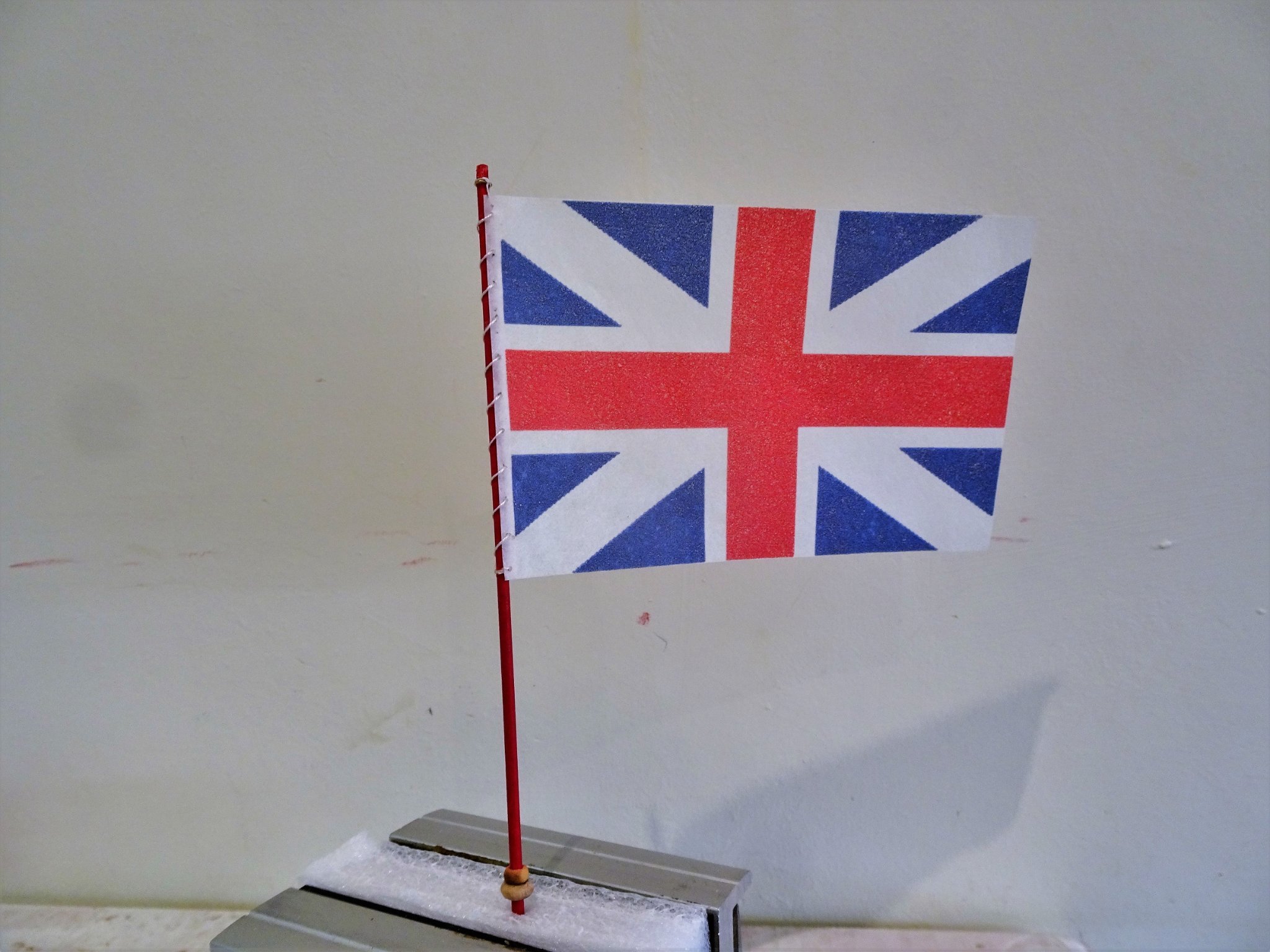
Post Forty-six Flag staffs and Flags. Two Flag staffs are required to be made from provided dowel. The staffs have decorative features in the form of wooden balls, but there is scope to elaborate the decoration if desired. 2907 I added extra balls and enhanced the Truck slightly. One small puzzlement I had was that with the staffs cut to the plan dimensions the Fore-staff was the same height as the Main-staff when fitted. Completed Broadside photos seemed to indicate that the Fore-staff was slightly shorter. Chuck has provided two flags to adorn the Barge, The Royal Standard and the Union Flag. The Royal Standard is of the period 1704-1714, and the Union Flag 1606 – 1800. Both are produced using the print on tissue paper method, in my opinion by far the best medium for model boat purposes, unless those models are very large indeed. For hoisting the flags, I will use a series of Ribands to secure the Flag, with the topmost ring attached to the mast truck. The Royal Standard Before I started messing with the flags I took the precaution of taking copies just in case things went pear-shaped. 2847 The copies were printed on Modelspan tissue. 2891 One of the spares was attached to a jury staff to allow me to play with folding and draping technique. I wanted to get the feel for how the flag would perform during this stage without risking the kit provided versions. 2892 The flag was wetted down using the spray fixative and teased into shape. The proper Standard was then fixed to the Flagstaff. 2914 I had a slight issue with the top of the hoist tearing away from the staff but the fixative held it in place once set. I was after a loose drape so as not to obscure too much of the colourful design of the standard. The Union Flag 2920 The kit provided Union Flag. These are always more problematical with the tissue method because when draped the transparency allows the red cross to show thro’ the white sections giving the impression that the ink has run. 2924 This is the effect I mean and this version will not stand. I couldn’t seem to get the drape I was after and was not at all happy with this result. Nothing for it but to print off some Union Flags onto Modelspan. I used 21gsm weight. 2926 I had thought that the Union Flag was a tad large for the Foremast and would likely to cover the foremost oarsman at the bow. I reduced the size a tad for these Mk 2 versions and added a hem to the hoist side. 2928 The Mk 2 flag attached to the staff; it has been sprayed with fixative to seal the colours. 2945(2) 2943(2) 2942(2) 2940(2) 2936(2) The Flag staffs are not glued in place and the flags may receive a little more dressing before the final display. In the final stages now and back to completion of the oars. B.E. 23/07/21


.thumb.JPG.4a0540b6a87451d986f235c262294428.JPG)
.thumb.JPG.ac7c8e56f35ade804741e50c1830a426.JPG)
.thumb.JPG.3bbe8d03ad9c3e8edc1c4b1305307517.JPG)
.thumb.JPG.6240d59d34c74daa9225b6e1e2d53809.JPG)
.thumb.JPG.aa6e40418861b37798d431527b839a87.JPG)
- 185 replies
-
- 15
-
-
-
- queen anne barge
- Syren Ship Model Company
- (and 1 more)
-
Nice work Richard, you may well find that the falls of the Main Yard Brace cover that scarph. B.E.
- 104 replies
-
- 2
-
-
- pegasus
- victory models
- (and 2 more)
-
You will find it in Volume 11 page 188. B.E.
-
Well done Phill, that’s a fine planking job. 👍 B.E.
-
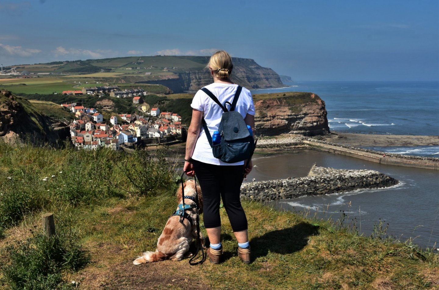
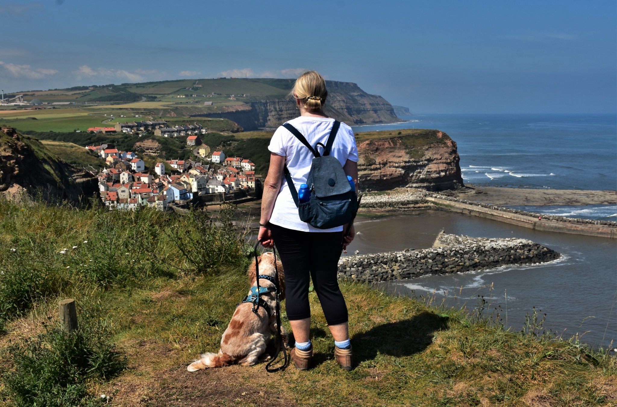
Thank you Matt, Bob, and Glenn. @ Matt - here's a photo of our last visit in 2019 before the world went mad. Looking down on Staithes my favourite village, and anticipating the wonderful Fish and Chips and Ale we will enjoy when we get there. We will certainly be re-visiting Staithes if the weather is kind to us, as it was in 2019. @ Glenn - I think the Hobbits live in the Middle lands of England, based on where Tolkein lived for many years, I go to Yorkshire to escape them 😀 Cheers, B.E.
- 185 replies
-
- 12
-
-

-
- queen anne barge
- Syren Ship Model Company
- (and 1 more)
-
Post Forty-five Working the Oars continued. Ten oars are required, and it is simply a case of getting down to this repetitive, but rather satisfying task. I used both scalpel blades and sanding sticks to achieve the required results. There is no real way of speeding up the process, but a jig as previously described does help with the tapering of the blades. For each set of five I prepared all the shafts first, glued them into the Looms and added the handles, I then set them aside for the glue to cure. The blades were then made. Final sanding of the shafts and the rounding of the handles was then done before adding the blades. Annoyingly one of the shafts developed a slight curve. 2831(2) I tried clamping in a vice and applying heat, to no avail, then I used the Quad hands with a central weight to straighten the shaft, again applying heat. This seemed to work after a couple of repeat treatments. 2843(2) The first five completed, but still requiring a final cleaning up. At this point I cleaned up the rather neat little oar racks designed by Chuck and glued them to base boards of 100mm x 25mm cut from the bulkhead frets. 2825(2) I think fixing to separate boards more convenient than attaching to what will be the base yet to be made. 2827(2) Pitch Pine stain was used to enrich the Cherry Wood. 2839(2) A trial fit in the racks. Work will now continue to complete the oars, but in the meantime the wilds of North Yorkshire are calling. B.E. 07/07/21
.thumb.JPG.cfc4ce05ea4ca5059b84cbd2f261c6a9.JPG)
.thumb.JPG.38caaf321a8bb5c4429031d0ee8ca63a.JPG)
.thumb.JPG.7e0fffb4849273d2e0ca888402c15b2a.JPG)
.thumb.JPG.bd734fc61a91120e013cbea230d962ba.JPG)
.thumb.JPG.65b571f46e80fab56442dd83e6577c71.JPG)
- 185 replies
-
- 14
-
-
- queen anne barge
- Syren Ship Model Company
- (and 1 more)
-
What a fabulous model, and great photos, you must be well pleased Glenn. You have produced an excellent log which will benefit those who take on this wonderful kit, which I too fully endorse. Thank you for the mention, and I look forward to your next project. Regards, B.E.
- 778 replies
-
- 3
-
-
- cheerful
- Syren Ship Model Company
- (and 1 more)
-
It's worse than that Matt, he's not noticed that there's no bottom in his boat. 😄 Thanks for looking in on the build.👍 B.E.
- 185 replies
-
- 5
-
-
-
- queen anne barge
- Syren Ship Model Company
- (and 1 more)
-
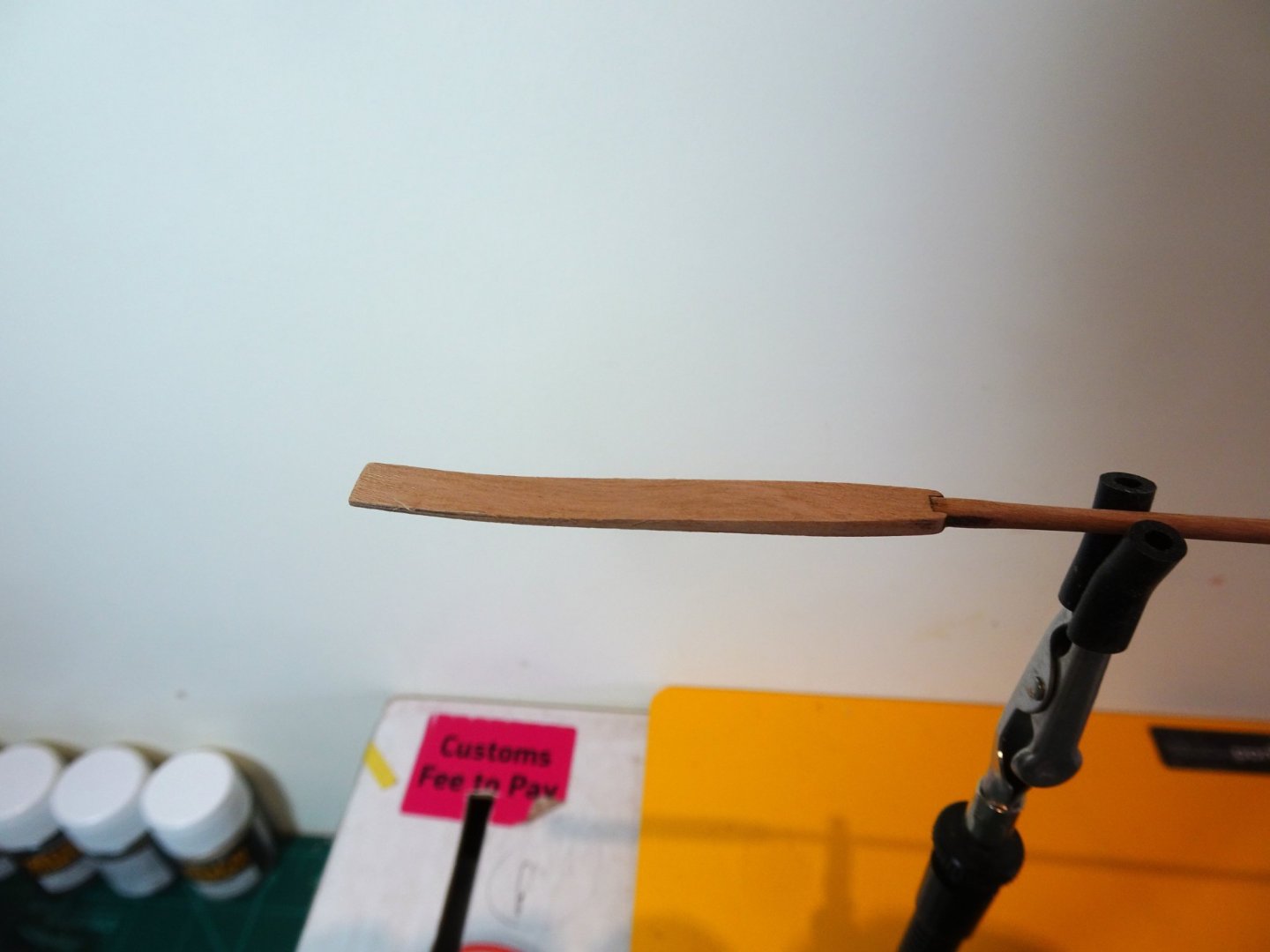
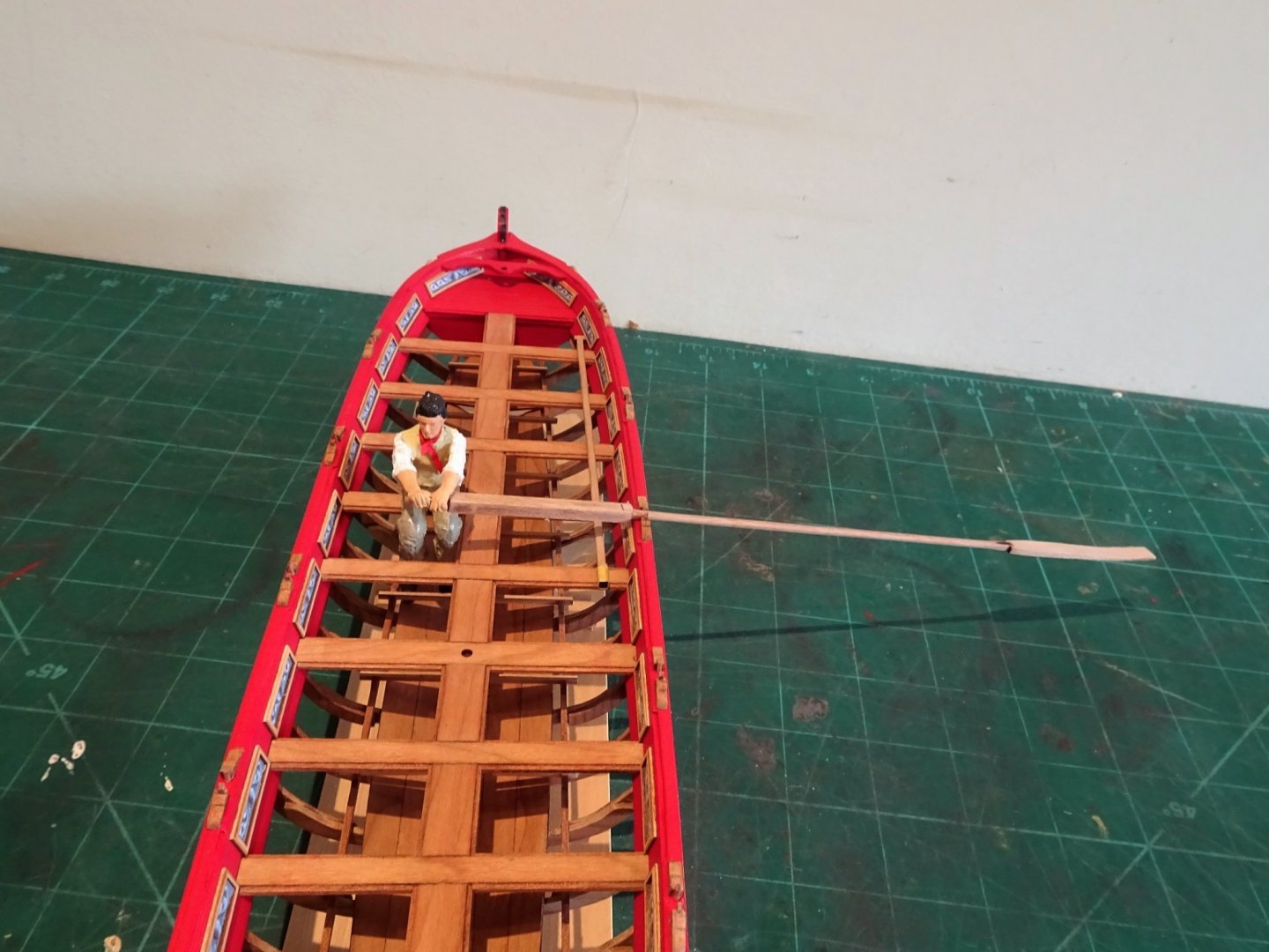
Thank you Chuck and Glenn, there is a small number of excellent builds that I have gratefully made full use of as reference works. Having followed your Cheerful build Glenn I can envisage what a great job you will make of the Barge. Post Forty-four Tholes and oars The thole pins are two part pre-cut tiny pieces where the laser char is fiddly to remove, but something that is necessary if a natural finish is required rather than a painted one. I haven’t decided on this yet so more attention has to be paid to char removal. 2751 I used the shaft of a partly made oar to set the distance between the pins. The paint on the capping rail was carefully removed where the tholes sat to provide a better bond for the pva. 2809(2) A days work to fit the Thole Pins, I may yet paint them Red. The Oars or Sweeps The square section of the oar (the Loom) has slots each end; a long slot to take the short handle, and a short slot to take the long shank. I started rounding the shank by paring the corners to create an octagon and then rounding by turning it between my fingers using sand paper. Once I was almost there I glued the shank into the loom for final finishing. I was curious to see how the oar scale measurements compared with those given by Steel for a boat with the same breadth. Seven feet is the given breadth of the Barge, and for this size a Twenty-foot sweep is given. Chuck has indicated that the shaft is left a little long to give purchase whist rounding. This equates to 6mm excess and once removed results in an overall 19’ length of oar. I decided to leave the shaft length as provided which results in a scale length of 248mm equating to a 19.5’ oar length. I taped the square end over during the rounding process, which left a good tight fit into the blade, the final finish being applied once blade and shaft are glued together. I rounded the handle to a scale diameter of 1.9mm. which equates to a 1¾” diameter. The trickiest part is forming the blade which must be tapered and also have a slight curve to it. 2758(2) To get a consistent taper I made a simple jig from the oar blade fret. 2786 The tapered blade; down to 0.9mm at the outer end. A slight curve is then formed by wetting, followed by the hairdryer treatment to the blade held around a shallow curve. The inner end still need a little fairing into the shaft. 2782(2) 2804(2) The final test is how does the oar fit with the boat in its working position. For this I borrow my oarsman from the Pinnace. 2798(2) 2803 2797(3) 2796(2) 2791 I will now continue with the time-consuming business of completing the oars. B.E. 04/07/21

.thumb.JPG.edd29743e357078490ec4332701d083e.JPG)
.thumb.JPG.ebda55382272cf07623aa1d5d17c8939.JPG)

.thumb.JPG.fe9cea6bd2edd7dbcdedf192b8966f93.JPG)
.thumb.JPG.4526e40e5479d392a540dc59c1256ae7.JPG)
.thumb.JPG.35d8fd701dda00338321a5f8fb198315.JPG)
.thumb.JPG.144a5b74ff79594935e65783e3b50462.JPG)
.thumb.JPG.9b5247d85703170ae7c59a2272e46a72.JPG)
- 185 replies
-
- 18
-
-
-
-
- queen anne barge
- Syren Ship Model Company
- (and 1 more)
-
A superb build with great research and attention to detail. I can only dream of achieving such artistry in the decoration and paintwork, wonderful work. B.E.
- 2,699 replies
-
- 3
-
-
- heller
- soleil royal
- (and 9 more)
-
A great little companionway top you have made there Jason, are you going to glaze the lights?. I too passed on the hatchway taper, I felt that at the scale involved it may have looked like an error rather than an intention. B.E.
-
Well done Grant, a beautiful model. 👍 B.E.
- 109 replies
-
- 1
-
-
- medway longboat
- Syren Ship Model Company
- (and 1 more)
-
You surely are a master hand at this kit designing malarkey Chris, another irresistible model in the offing. 🤔 B. E
-
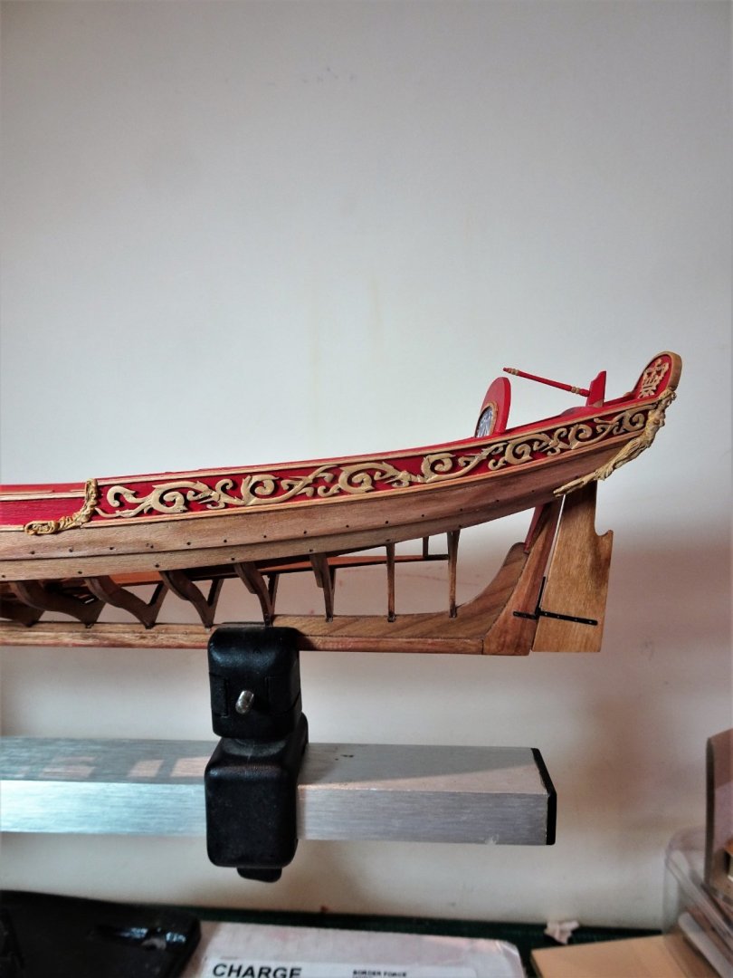
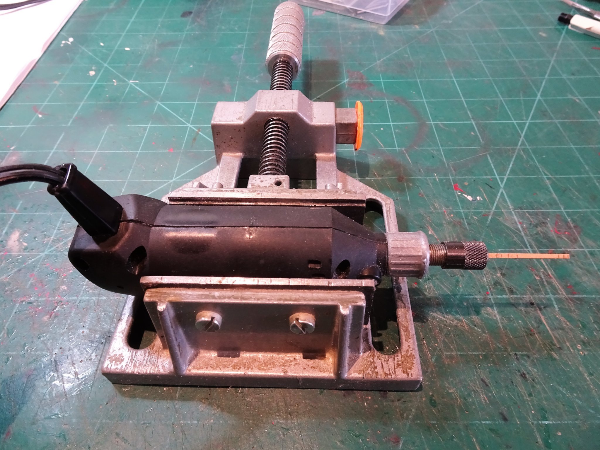
Post Forty-three Looking at the rudder I start by making the Tiller. 2649 A strip of Cherry square stock is secured in my Minicraft tool. 2653(2) Needle files and sandpapers are used to form the Tiller shape. 2661 Having cut a neat little mortise in the rudder head, the tiny tenon on the Tiller broke off so was replaced with a less satisfying brass pin. I may well re-visit the Tiller, they are quick and easy to make. The rudder comes pre cut with its distinctive hance but does require tapering towards the aft end of the blade. 2673(2) I have restricted the taper to the blade of the rudder, just applying a slight round above the hance. The taper is applied both top to bottom and fore to aft Dressing the rudder. I usually make working rudders for my models but after some consideration I decided to go with Chuck’s simulated version which gives a realistic impression of a properly hung rudder. 2684 The long lower pintle properly attached to the stern post is made an integral part of the rudder, slotting into a tab which represents the gudgeon on the rudder. 2689 When rudder and sternpost are brought together the effect is completed. 2711 I added ‘bolts’ to the rudder straps in the form of wire. 2708(2) 2707(2) With all decorative pieces at last released from their backings, it was a simple job to fix them in position using a few tiny spots of ca. I gave them a coat of wop before putting them into place. In the final stretch now with thole pins, oars, masts, and flags, left to do. B.E. 30/06/21

.thumb.JPG.51347a7235ae2b95997bfb826a9e4a9b.JPG)
.thumb.JPG.deed5162015a3942d9059f81e6976652.JPG)

.thumb.JPG.eeef6e27e4ac0cbcd7ade986ae82eaec.JPG)
.thumb.JPG.47c2c164f5b533c598801e411f09de0e.JPG)
- 185 replies
-
- 17
-
-
- queen anne barge
- Syren Ship Model Company
- (and 1 more)
-
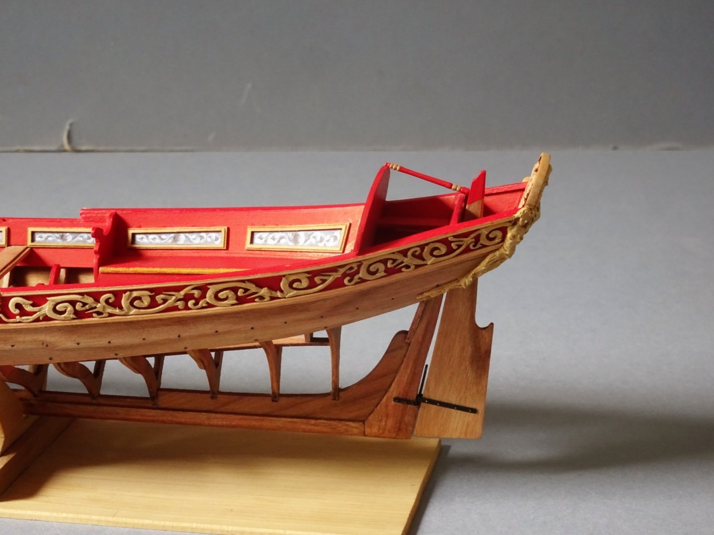
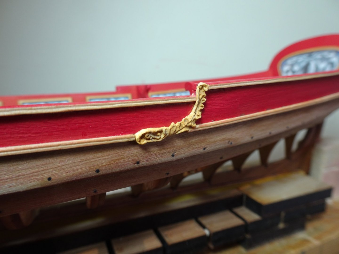
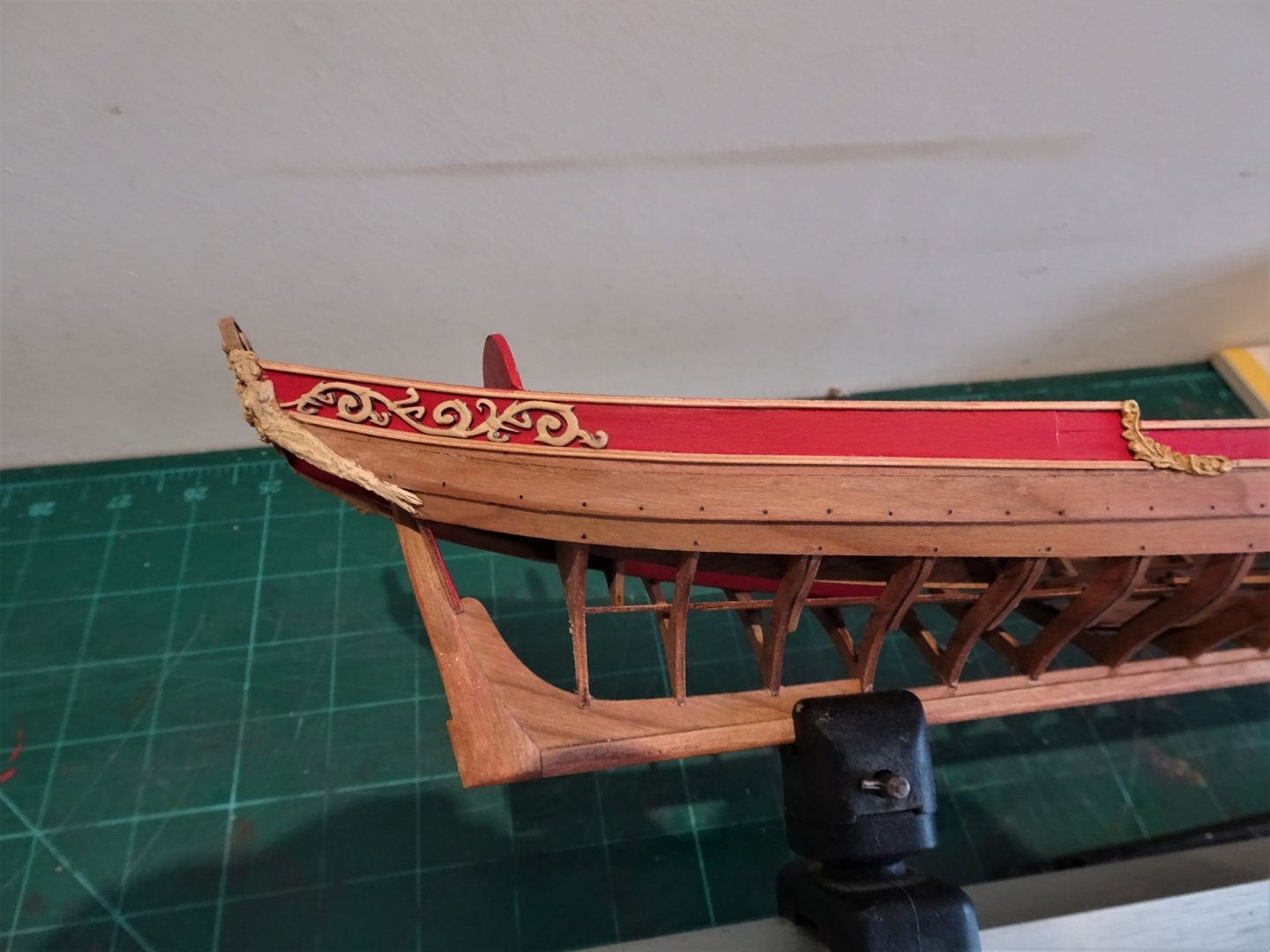
Thank you Glenn, Bob, and Hubac, and to those following along with this build.👍 Post Forty-two Resin decorations While I wait for the acanthus scrolls to release from the backing I attended to the remaining resin decorations. Firstly, the hull decoration at the break of the sternsheets. 2563 Fairly straightforward, small sections of the rails need to be removed to accommodate the fit. 2561(2) The final fittings are the Mermaid figures that adorn the stern. Somewhat trickier to fit, requiring removal of sections of the rails and capping of the Flying Transom. 2570(2) The figures also need a gentle tweaking using hairdryer heat to take the stress out of the fish tail end where it follows the round of the hull. I found it tricky to attach the figures without marring the finish, and they will inevitably need touching up once in place. 2602(2) 2598(2) 2587(2) 2585(2) 2583(2) I’m not entirely satisfied with the colour reproduction of the resin castings, they are not a bad match to the bare Boxwood, but I rather feel a little more richness is called for. With the resin decorations in place, I was happy to find that the first of the Acanthus leaf Boxwood decoration finally released. 2646 Relieved to find it fitted between the rails. They won’t be fitted into place until the whole set is available. I wonder if I should apply a coat of wop before fitting. In the meantime, I can attend to the rudder. B.E. 27/06/21
.thumb.JPG.83472e7449ccc83a6fc868982b686ff6.JPG)
.thumb.JPG.ccbef00634a47d4508929e30a6682d00.JPG)
.thumb.JPG.b721bd69a871b91e59555205ec230101.JPG)
.thumb.JPG.eca67e5700d3d8b7b6543e1277b21503.JPG)
.thumb.JPG.6d6c7d47c097fe15049a699b58b34652.JPG)
.thumb.JPG.912ebc4727703928628ded832908a48f.JPG)
.thumb.JPG.617b3cf77410a1ee08a224cff2098425.JPG)
- 185 replies
-
- 16
-
-
-
- queen anne barge
- Syren Ship Model Company
- (and 1 more)
-
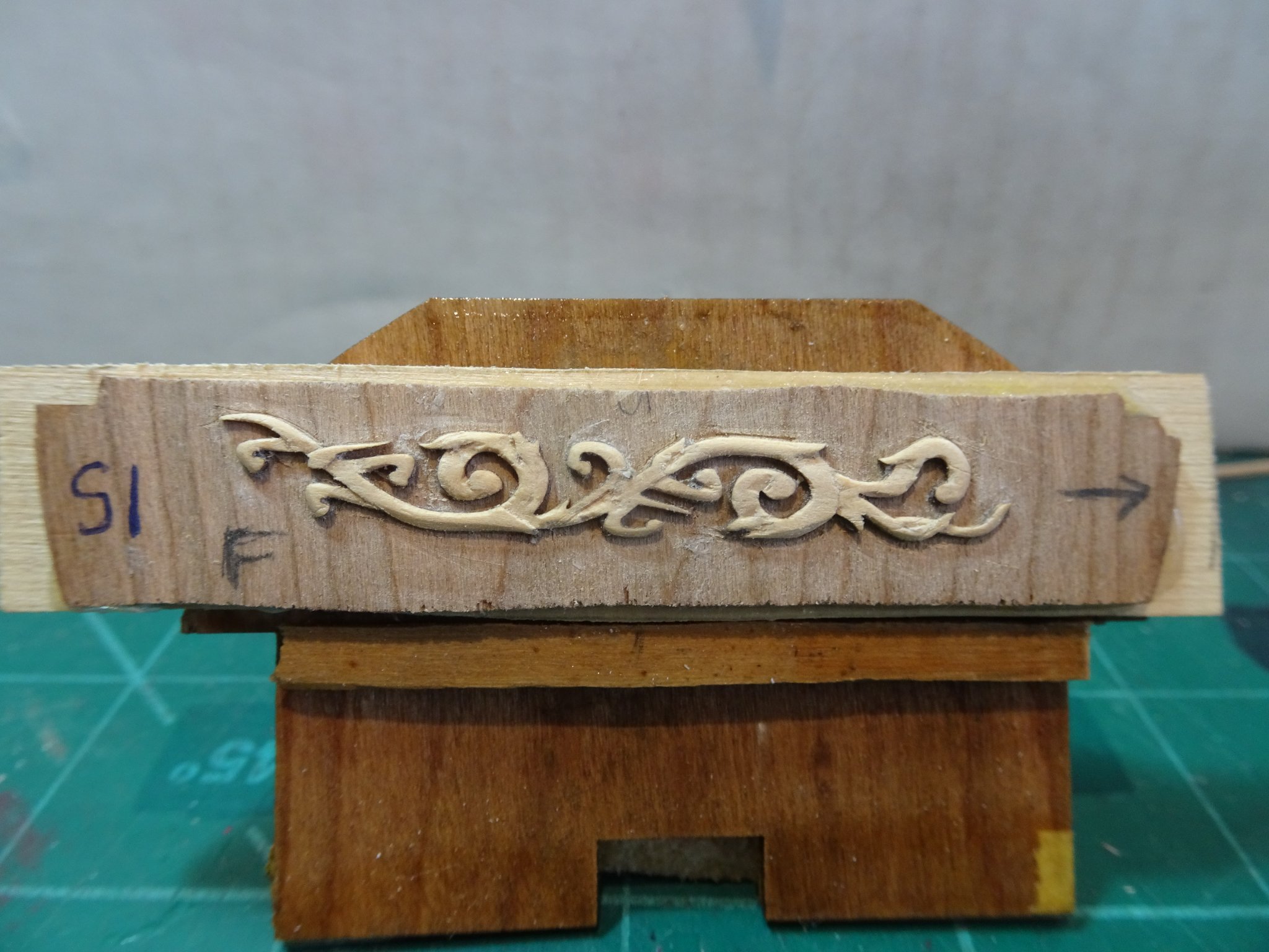
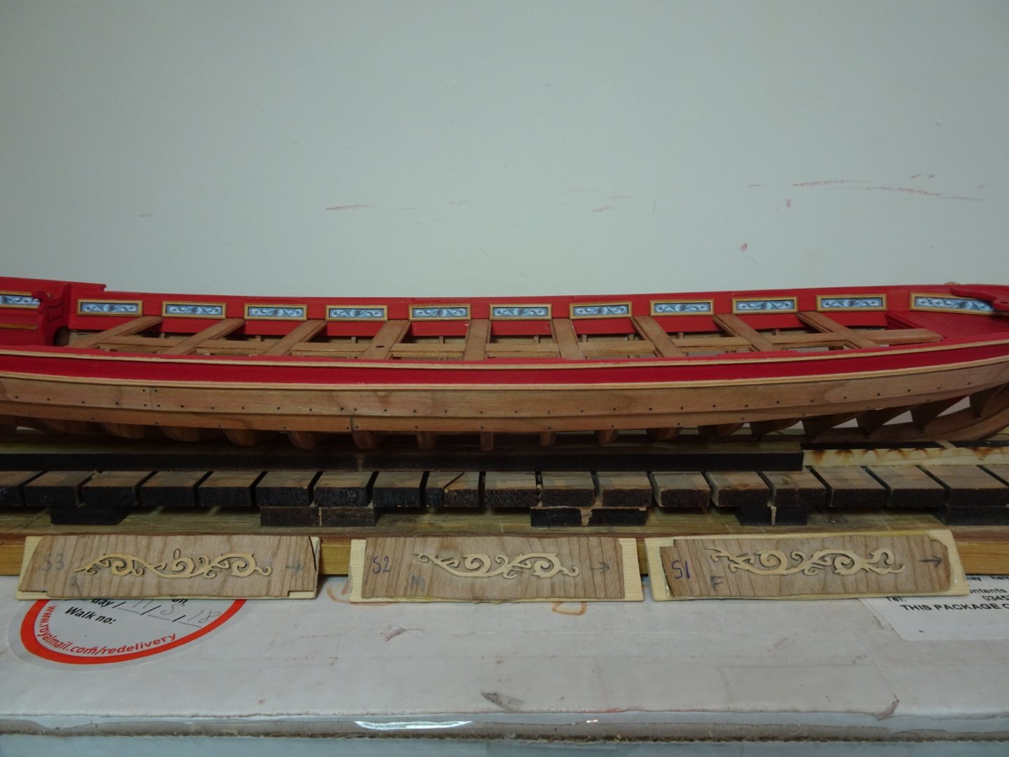
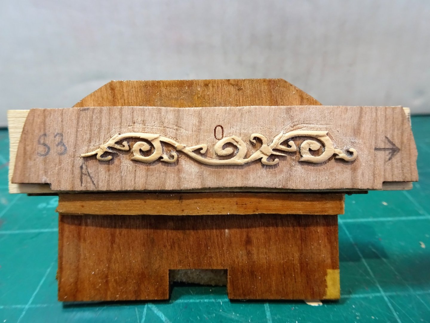
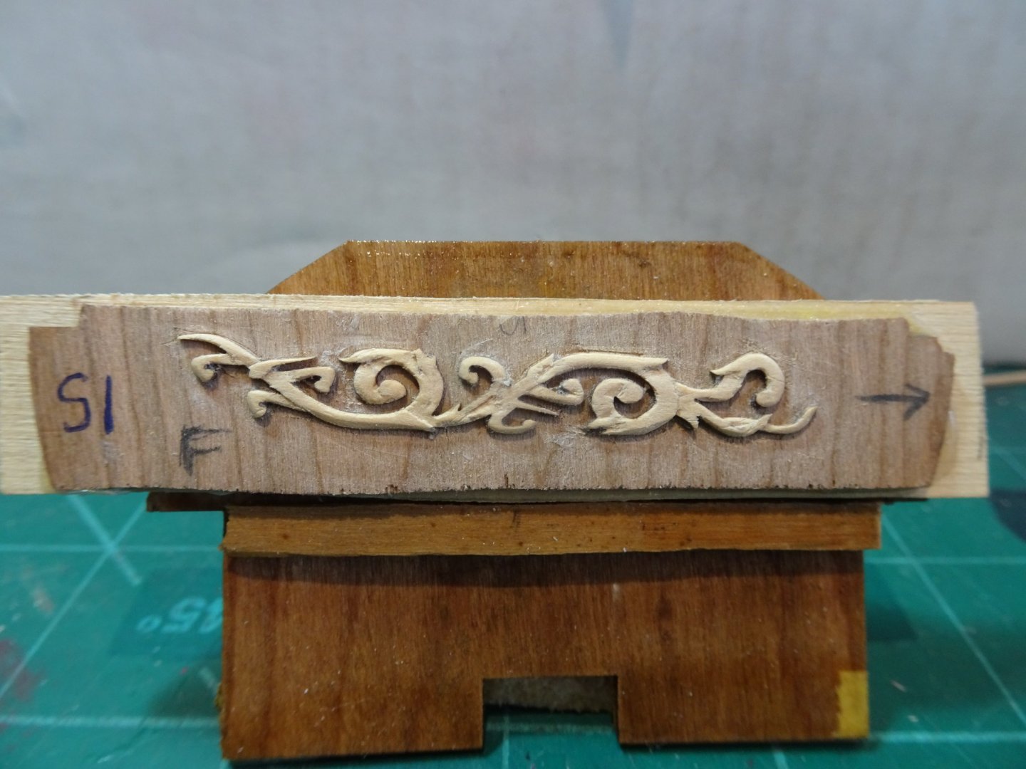
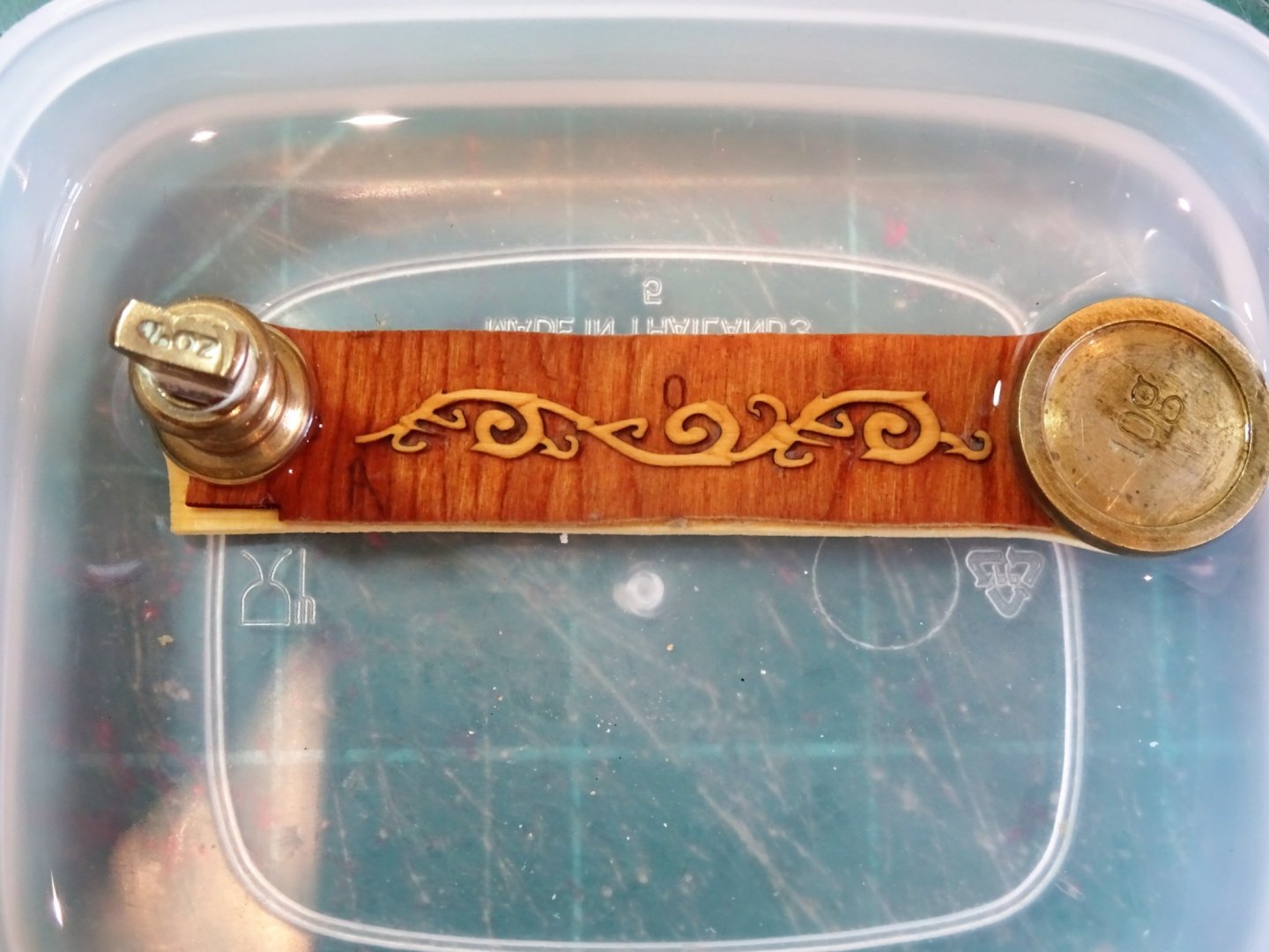
Post Forty-0ne Acanthus whittling I have previously had a dabble at this which ended in a broken strip, and I put the process into abeyance whilst I got on with other stuff. Round two Having carefully attached the blanks to backing boards this time using a Pritt stick I hope for better results. 2545(2) I start by marking the stop cut lines and attend to these first. Micro chisels are used, and the direction of the grain is carefully noted. 2546(2) It is then a case of carefully paring a round onto the detail using a scalpel, fine sandpaper, and the edge of the chisel where required. 2542(2) I keep a copy of the Chuck’s examples in front of me as a reference. 2549(2) To ensure uniformity I prepared all three each side before I attempt to remove them from the backing. 2553 2552(2) 2551 Nearly ready for release, a little more smoothing and polishing. Portside decoration The same procedure for the Port side, but to ease interpretation of the carving lines I flipped the photo of the finished work provided by Chuck. 2611 As I write this post the first of the Acanthus carvings has been immersed in Isopropanol for some thirty hours and is still stubbornly hanging on in part to its backing. At this rate with another five to go I think I’ll probably lose the will to live! B.E. 26/06/21
.jpg.72750fa723c5c1760ce3e5b89ee8d451.jpg)
.thumb.JPG.8c59878ea7f4976f603e40e94d55225b.JPG)
.thumb.JPG.be8f23087a8eb57796b5775bf16402cb.JPG)
.thumb.JPG.3d46112794d5203a0311d9a4967a9860.JPG)
.thumb.JPG.21507c102b9b1cf071d6bdb65271246f.JPG)
- 185 replies
-
- 14
-
-
-
- queen anne barge
- Syren Ship Model Company
- (and 1 more)
-
Thanks Jason, I agree the figure needs (a lot) more work and in his present state he certainly won't make the cut. I have been in touch with the 3d model company who say they can do it but require me to provide the clothing, which is a bit problematical.🤔 I'll revisit the subject once I have completed the barge. B.E.
-
It looks magnificent Glenn, almost makes me regret not masting and rigging mine, but I did satisfy that urge on the smaller scale Alert. Great work.👍 B.E.
-
That looks like a system that would work, but can you get a block down to 1mm in length?, your prototype looks somewhat larger than that. Chuck supplies 2mm blocks in Boxwood which would save you the trouble, and those are really tiny. For my own humble efforts I simply looped fine wire around the block and superglued it to the sides, leaving a little loop at the top for the strop. at the bottom the wire was twisted and trimmed close. Not entirely authentic but sufficient for the scale involved. B.E.
.JPG.fe9256f66a6b437fe370dfb3dd728d74.JPG)
.JPG.2da3d2cd46b1be00bb0b73c566e7b306.JPG)
.JPG.7ee03282474bdfe0deaa41b097846d59.JPG)
.JPG.09336db689b69175b366d3f3b97c61c4.JPG)
.JPG.f20aba6e984764d0dd08a4654330be95.JPG)
.JPG.77a1fce5607bab560aefb8a619424738.JPG)
.JPG.e310d62e697bbd122443d87b22ec0b8e.JPG)
.JPG.b20cb1bd13caa94d5b7a6eb6d92a2943.JPG)

.JPG.3264b3f2921ebd9d27df5512f40c40ec.JPG)
.JPG.51884e4733f5b6e3d62a2daab7445191.JPG)
.JPG.14f94168863a7d95dc236ff7d1e75819.JPG)


.JPG.fd0a0af81be79e7b391c789603310ded.JPG)
.JPG.66960b3e74700f4de123767aba8d156b.JPG)
.JPG.307de1ba8df1dd7520bc8b2aabb13603.JPG)
.JPG.f9665259e6b909d47f4f2fbbbe4da5e1.JPG)
.JPG.bc24ac0aa2dbf20ce2bb4578c785bd53.JPG)

.JPG.87092101fee9a2254cc64a12b7b45ab6.JPG)
.JPG.89db67182b442af4f10a09a228c3e9ba.JPG)
.JPG.83371a4efdcd309551cdf32b19f5b97e.JPG)
.JPG.040657540cb6e92f84ae7328dd92b6bf.JPG)
.JPG.7d280dc86b161927cd9a804864ed2934.JPG)
.JPG.0c48c67a87d912ef21cca66f80443e96.JPG)
.JPG.d4d288ad0998b0eac3b6e1881dcdb634.JPG)

.JPG.4c1fe6bc9dd1773d6211929915426958.JPG)
.JPG.c30d771c3f03e49bb928b86179156eeb.JPG)
.JPG.ab5d8fbd9167a3d67679e9a07a943fe2.JPG)
.JPG.9997a0707098e73ff0f4fc39948cd2a1.JPG)
.JPG.db61b5e7c21211a08b69f7dd494e763c.JPG)
.JPG.55a3550e1f68cefadc951b7503925fde.JPG)

.JPG.201faa0cdf352bfb9c8aed892d30ce42.JPG)

.JPG.fc22ad89d8b780f2fdb35c8f78c092e6.JPG)
.JPG.e4d9883ef81d94f9098d793792703776.JPG)

.JPG.b61a7b9f24c7b1986319a8380d7c83eb.JPG)

.JPG.2675cc88aeba35525497188ba623392c.JPG)
.JPG.a8b0ea5637c02e7fee6a8fcaf7f8cb5b.JPG)
.JPG.d3da974ea88322d85ad4ace3e44a4d4f.JPG)
.JPG.5cf283046095b79abc5bf8f389d22c8a.JPG)
.JPG.c9a3adbb560c142f84aaa2c3245698ea.JPG)
.JPG.bc31d6b84f22a3fdc69ba3f55d4a39e6.JPG)

.JPG.e0c8dca096fd4a4dedc75abf85038d84.JPG)
.JPG.7d8950dd850a987c379cdc71c5701b11.JPG)
.JPG.f236c11aa52f550b0c3d067b69a485ee.JPG)


.JPG.f61e4da4c0f46a4f64b8ffe0dc026e69.JPG)