HOLIDAY DONATION DRIVE - SUPPORT MSW - DO YOUR PART TO KEEP THIS GREAT FORUM GOING! (Only 20 donations so far - C'mon guys!)
×


RdK
-
Posts
120 -
Joined
-
Last visited
Content Type
Profiles
Forums
Gallery
Events
Everything posted by RdK
-
Hi Jan, Now that we started to count: my oldest card model is 40 years old this year and looks still (almost) the same ugly 😄 It is the Santa Maria and I posted a picture of it over at papermodelers in my Mayflower thread I think. It is as crooked as a small boy can make a ship 😅 But it is true that our card models will not last as long as the beautiful wooden ones. At least I do not think in 300 years from now anyone will posess any of my card models 😉 -R
- 77 replies
-
- 1
-

-
- Royal Yacht
- card
- (and 1 more)
-
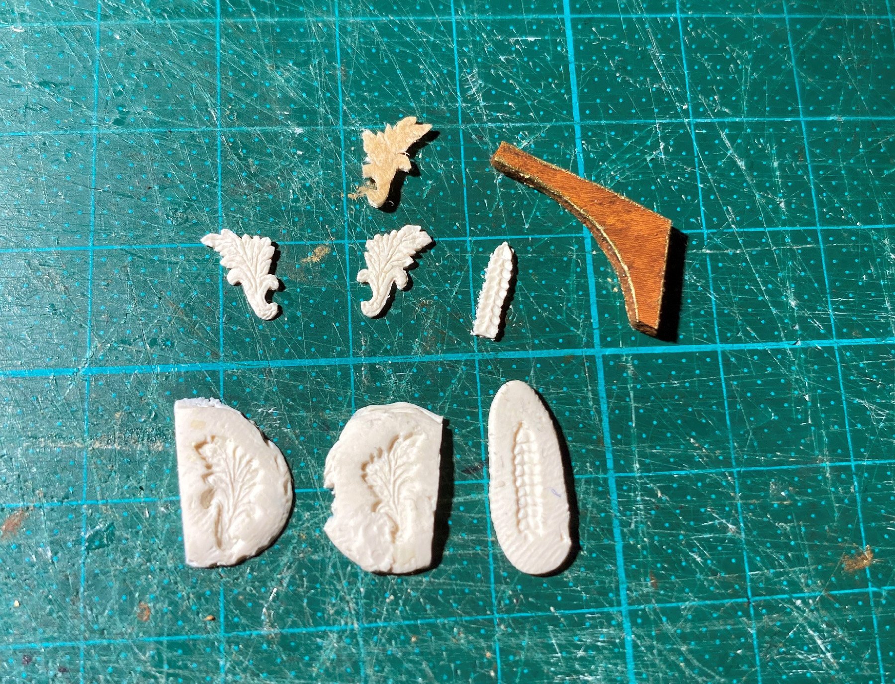
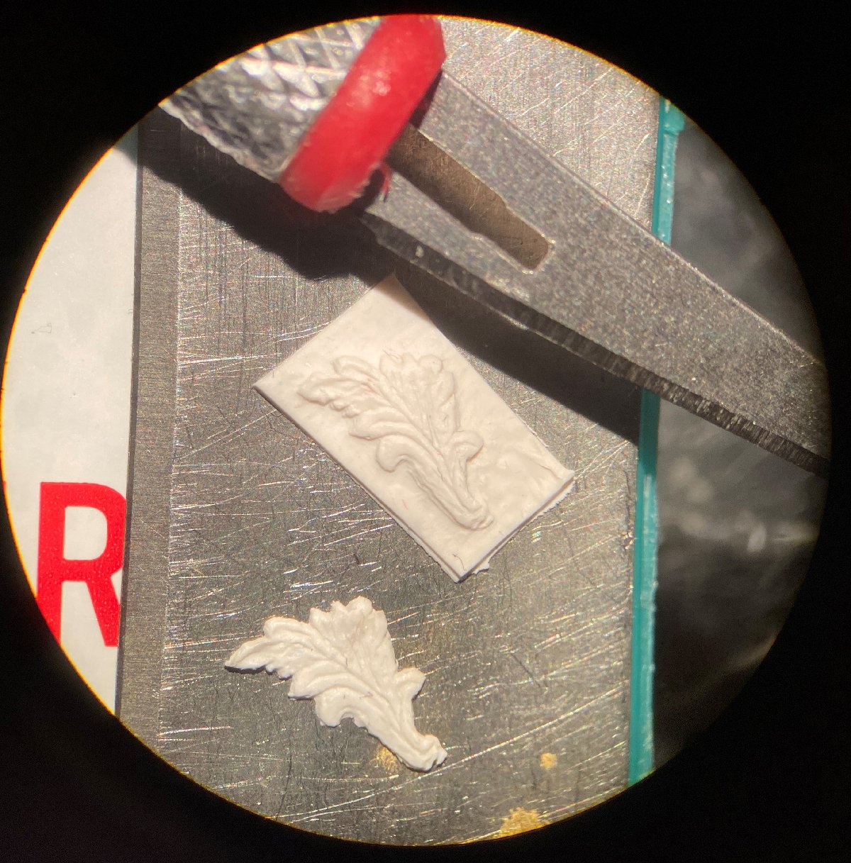
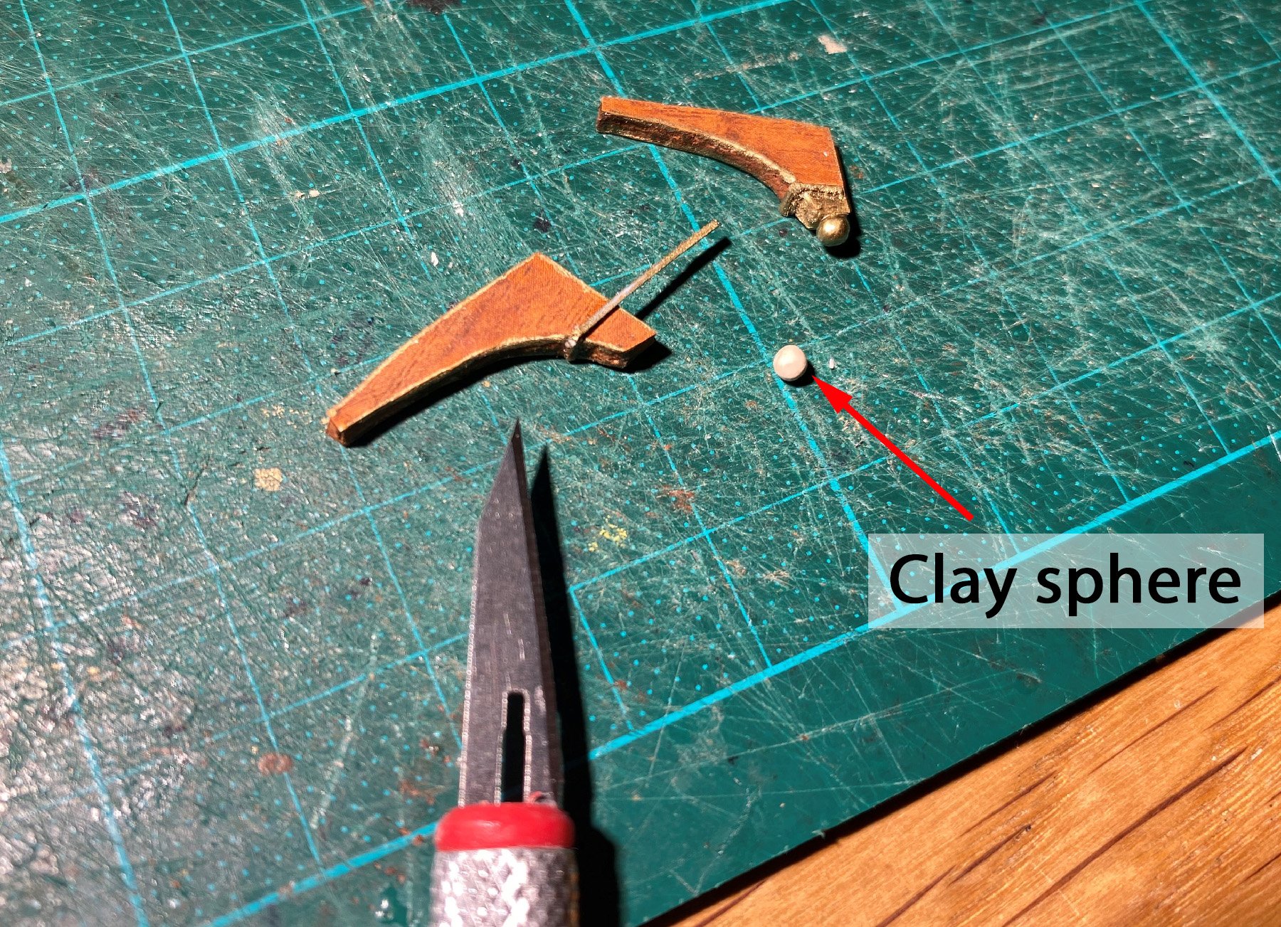
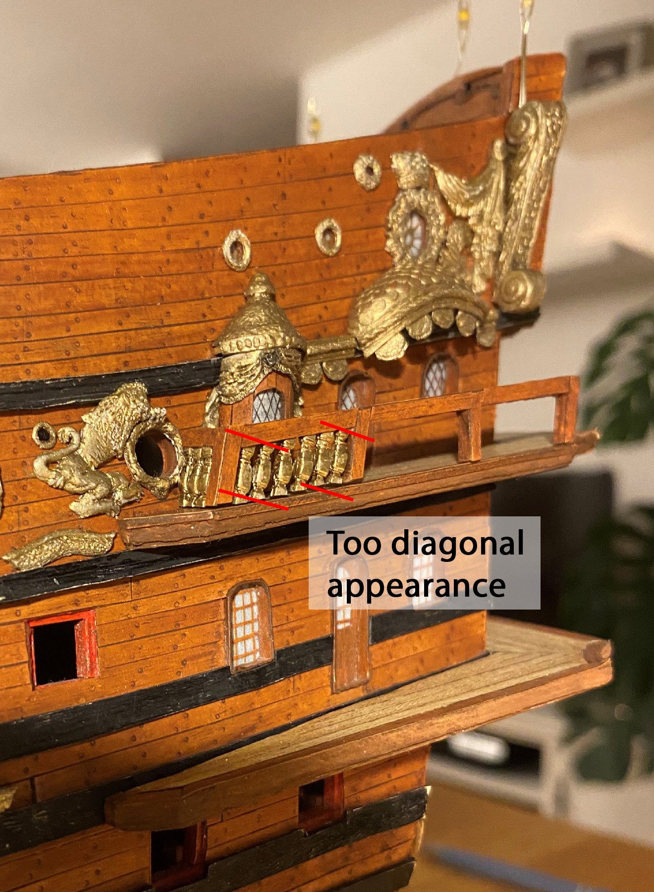
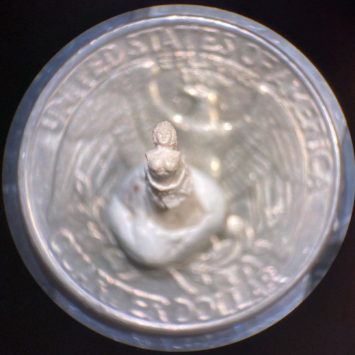
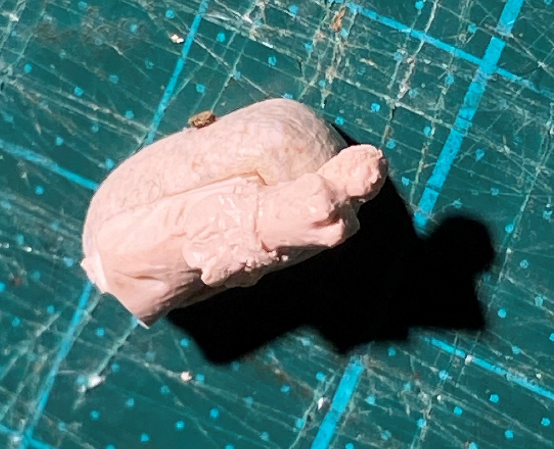
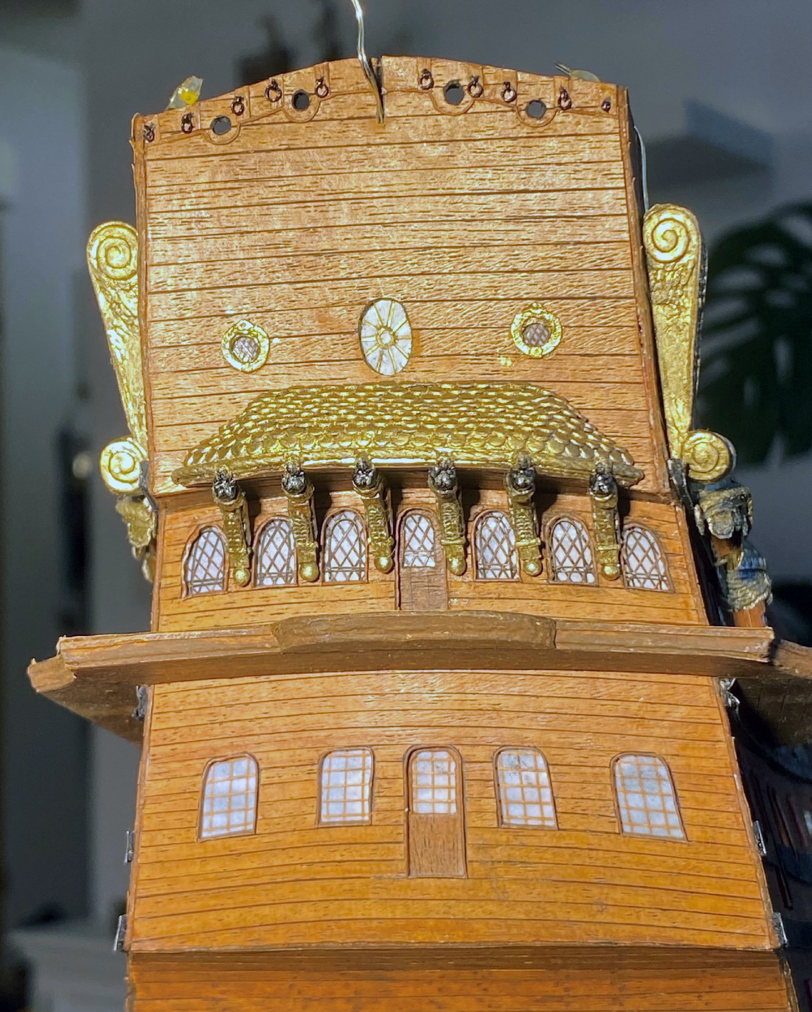
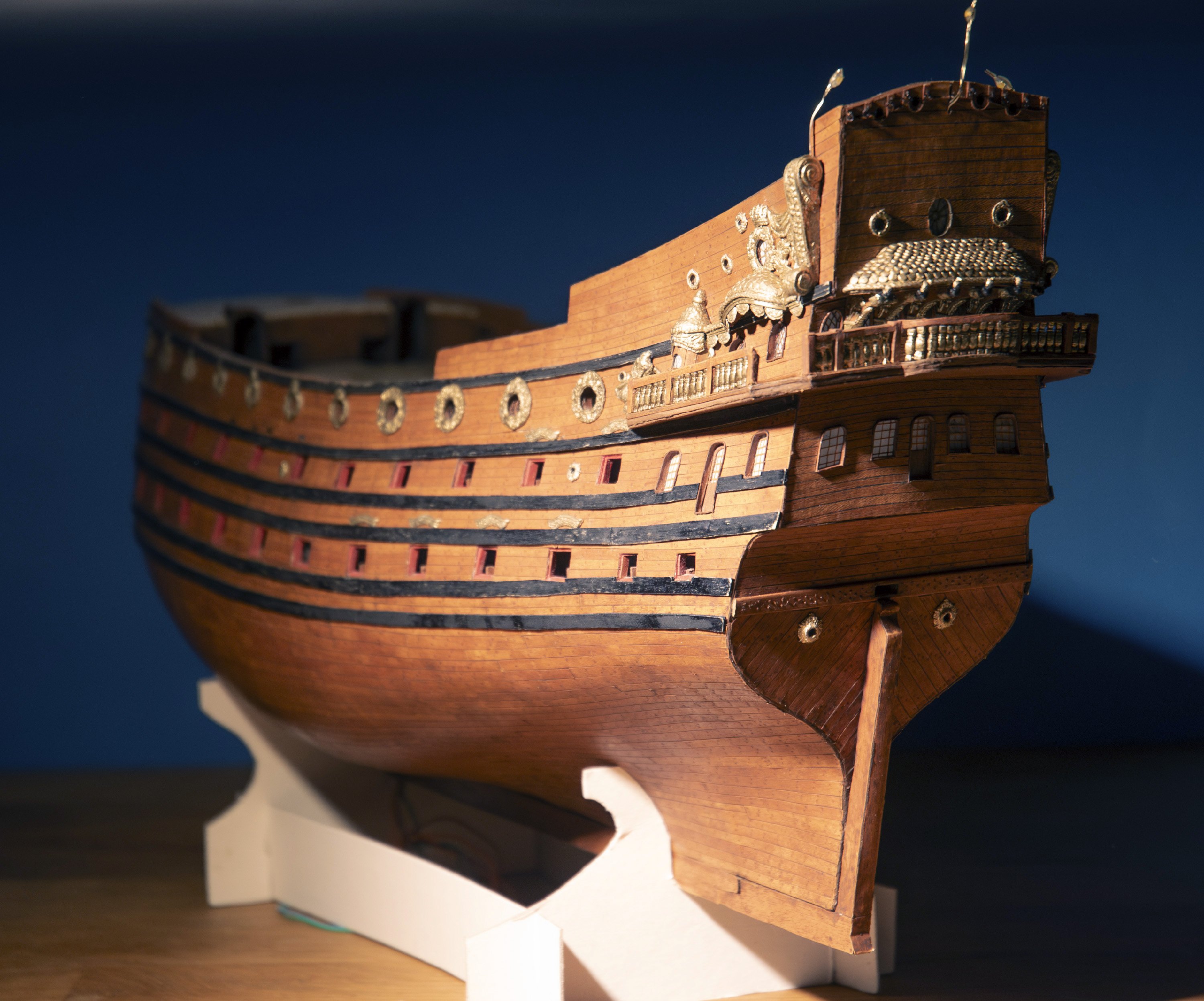
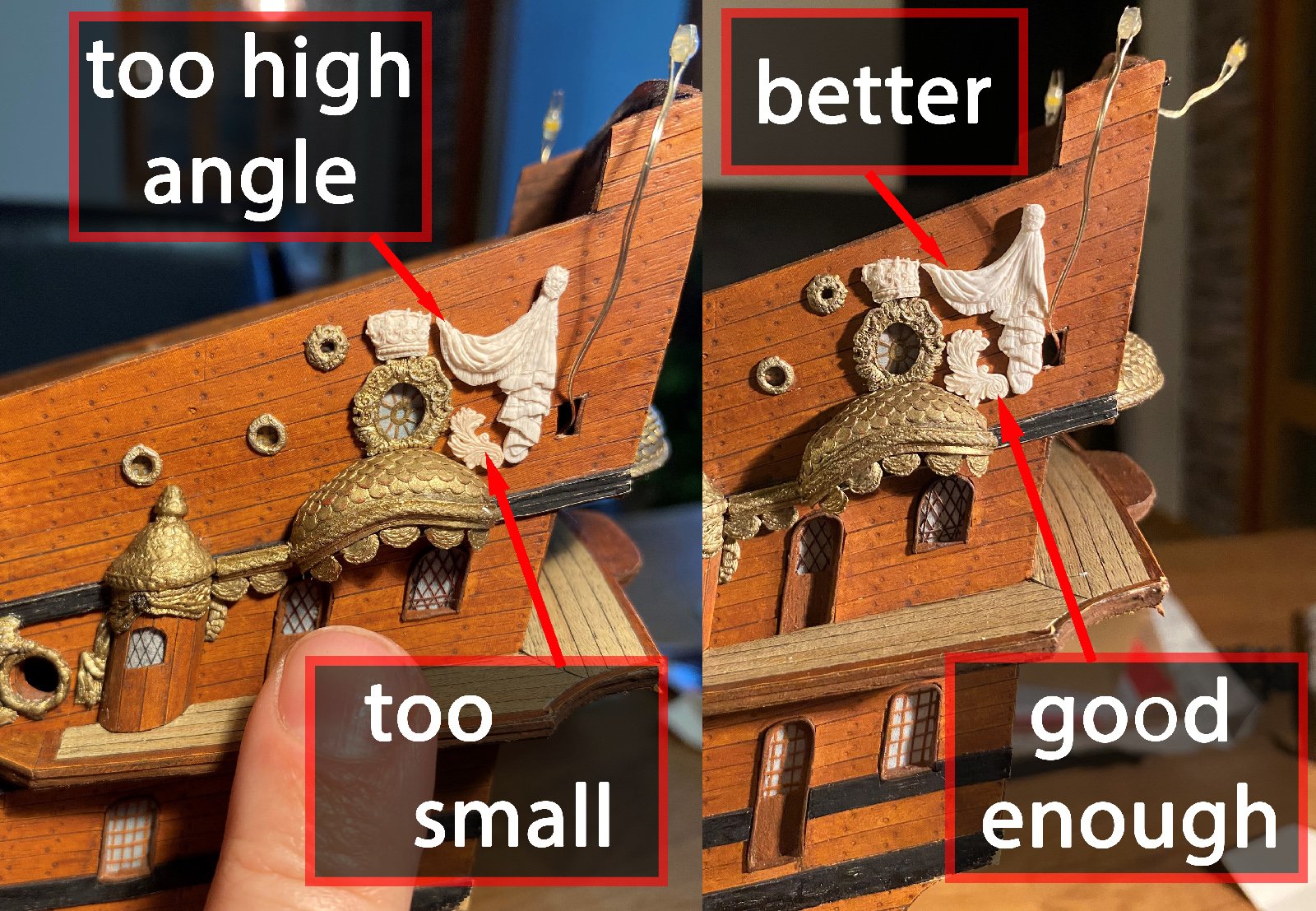
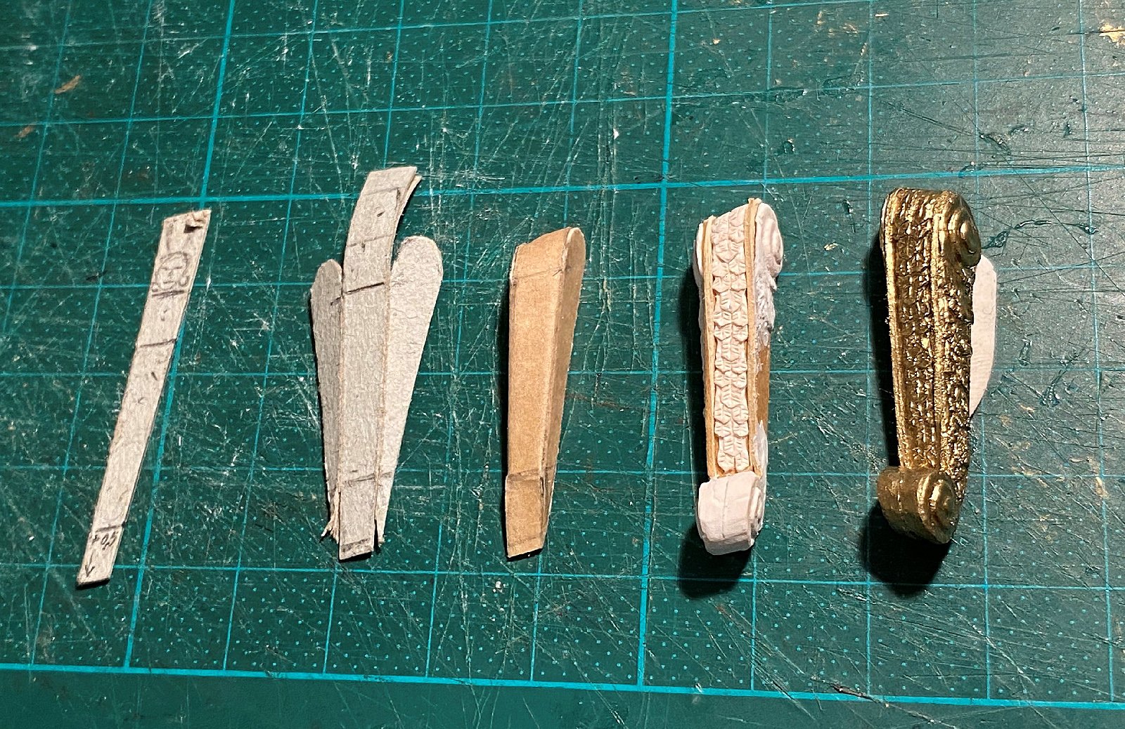
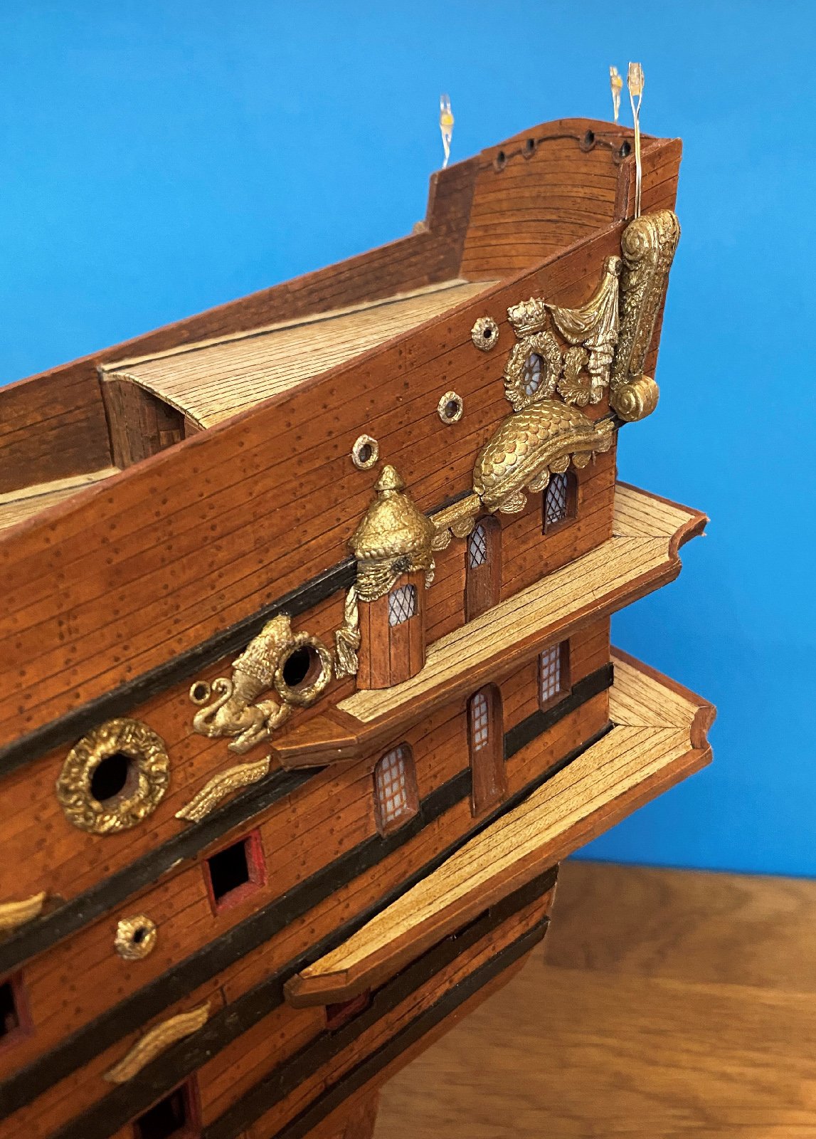
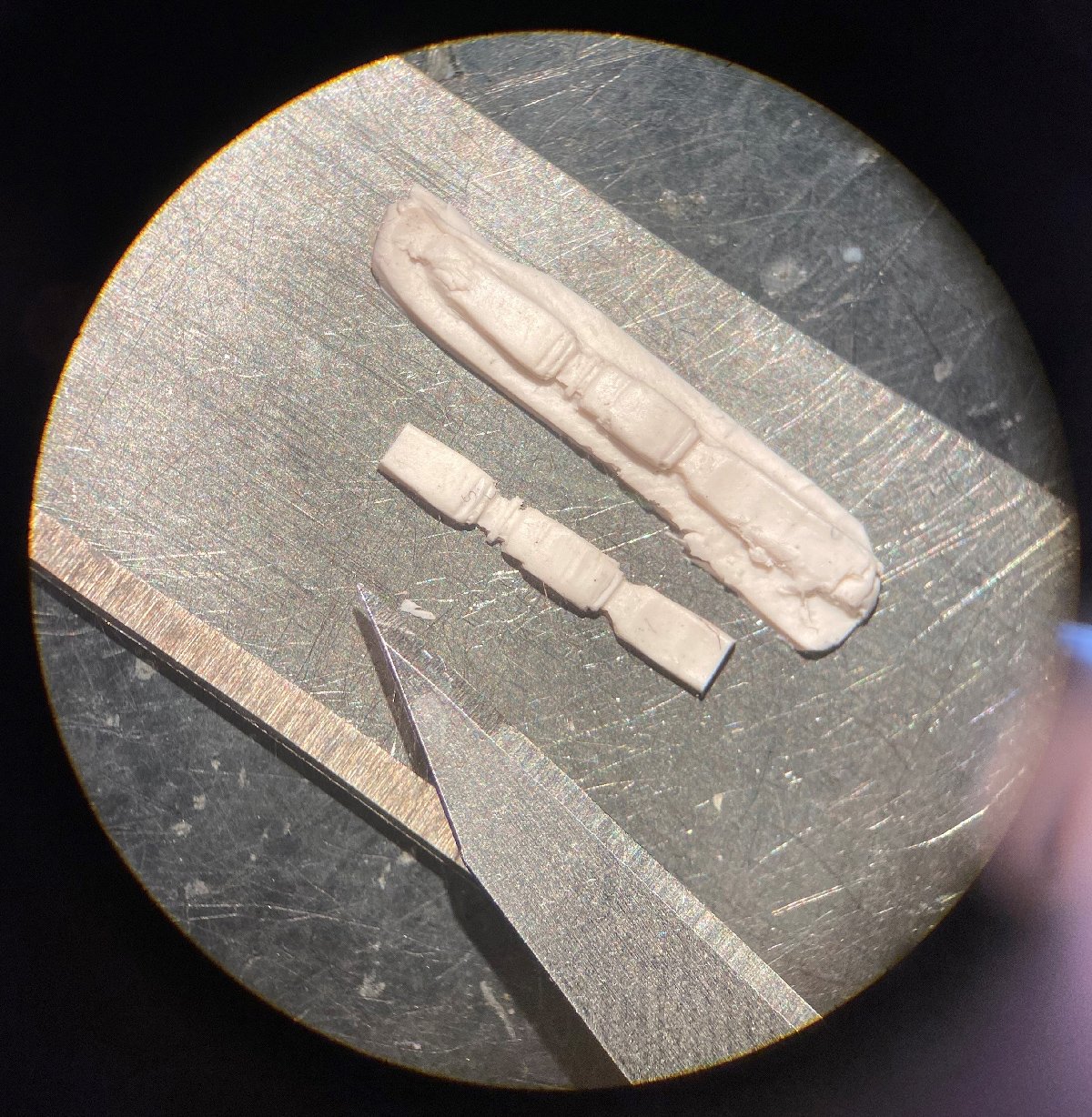
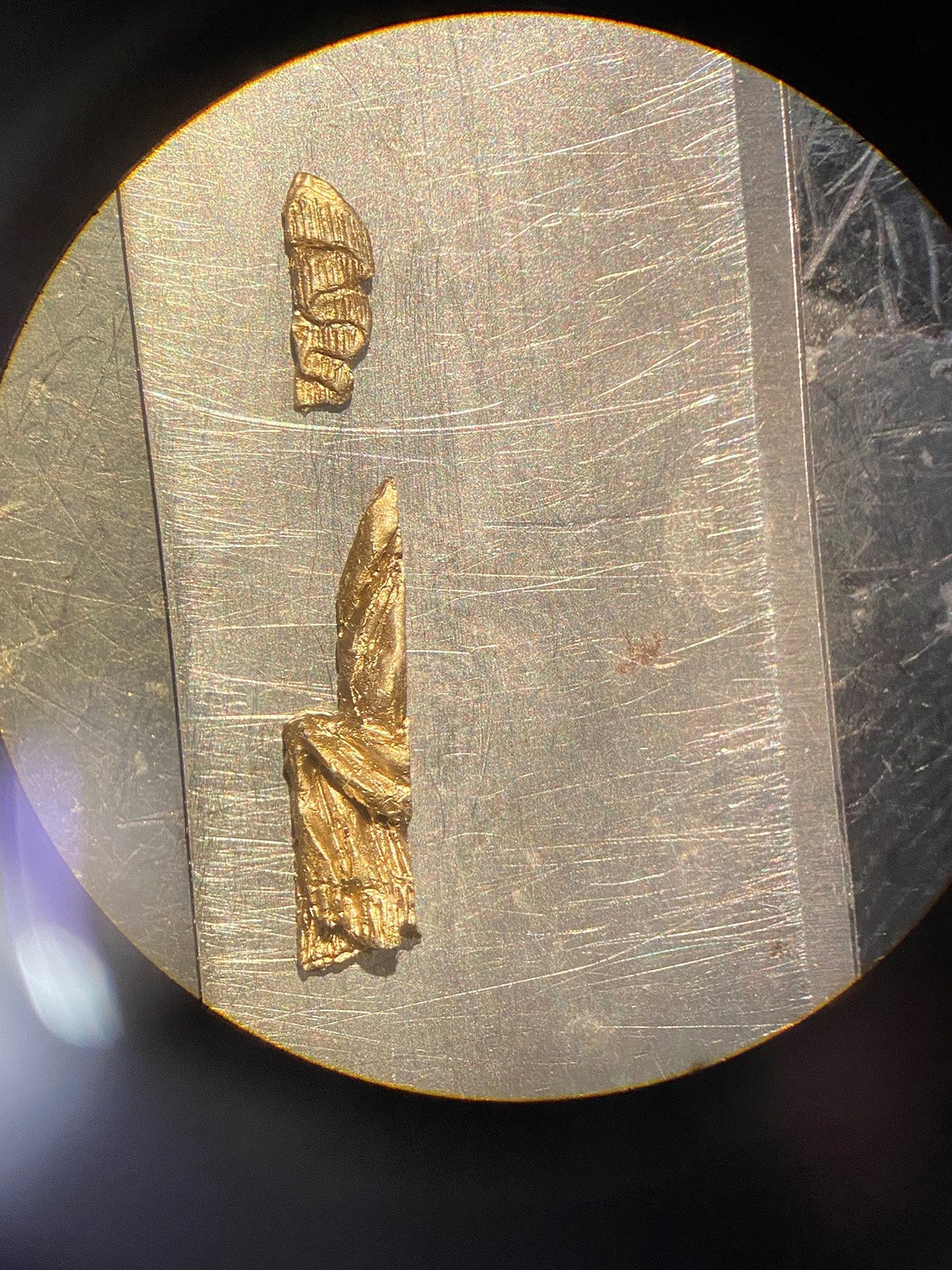
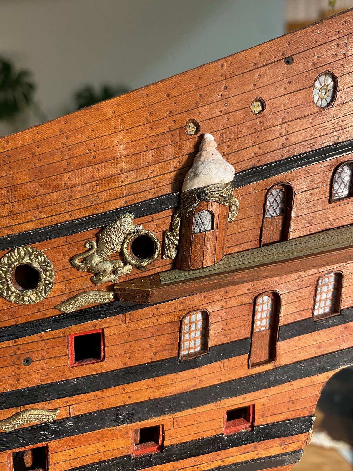
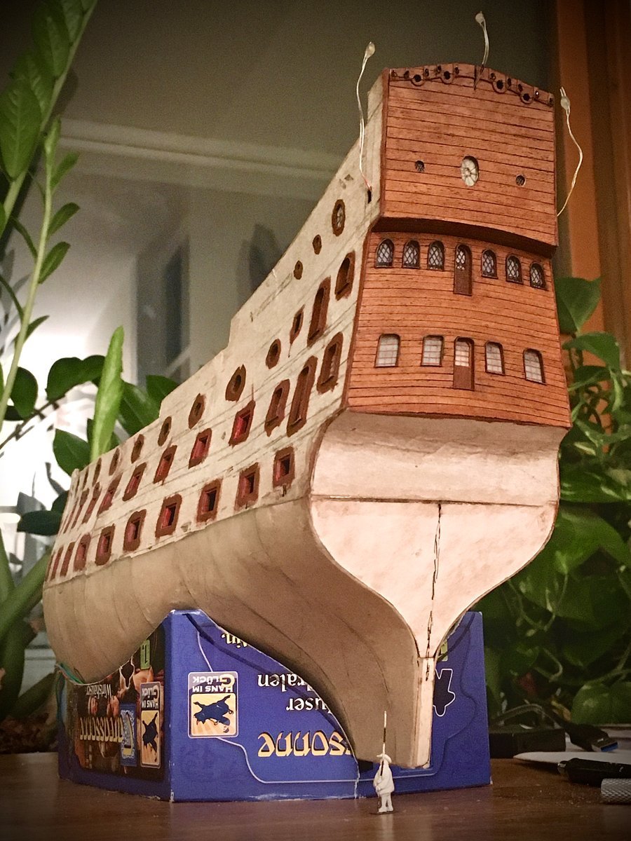
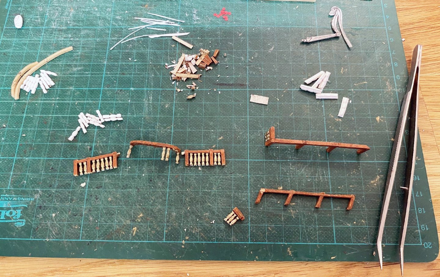
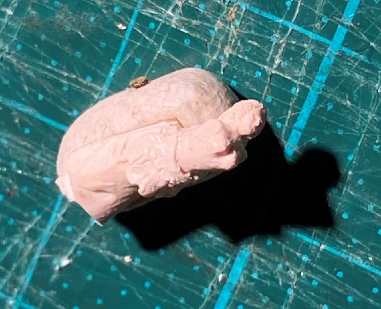
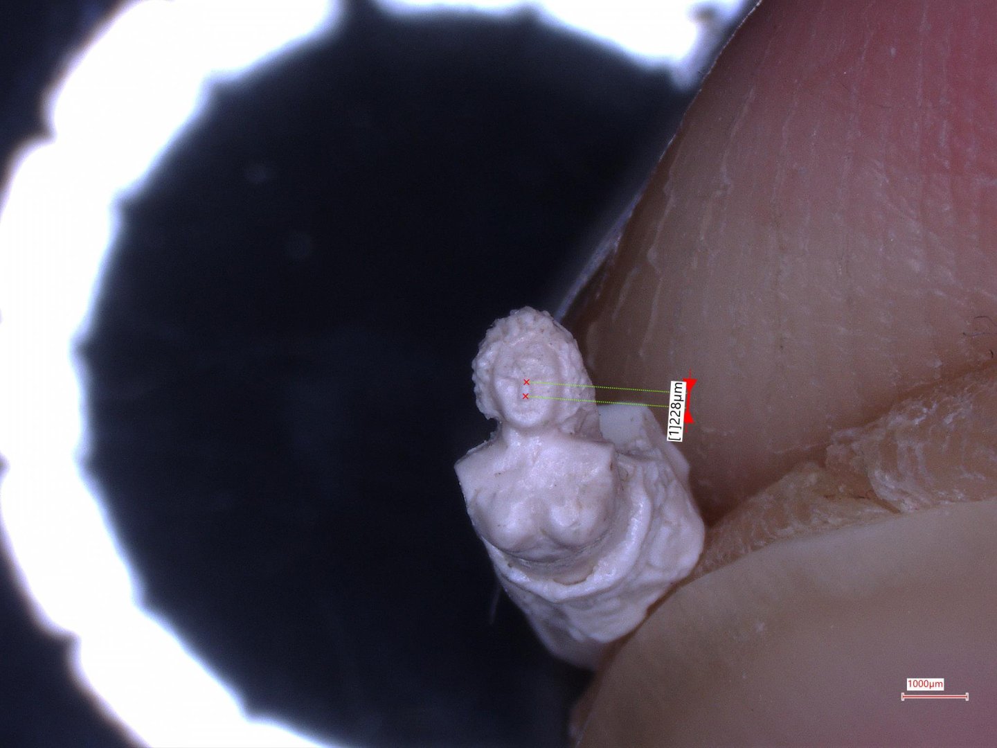
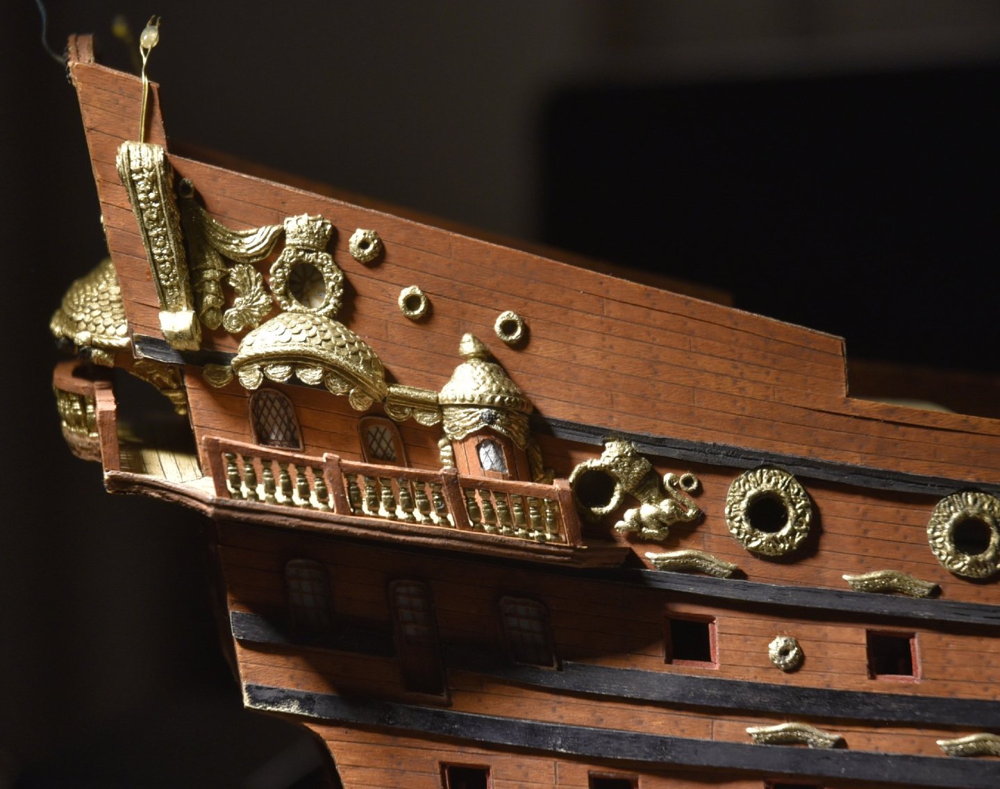
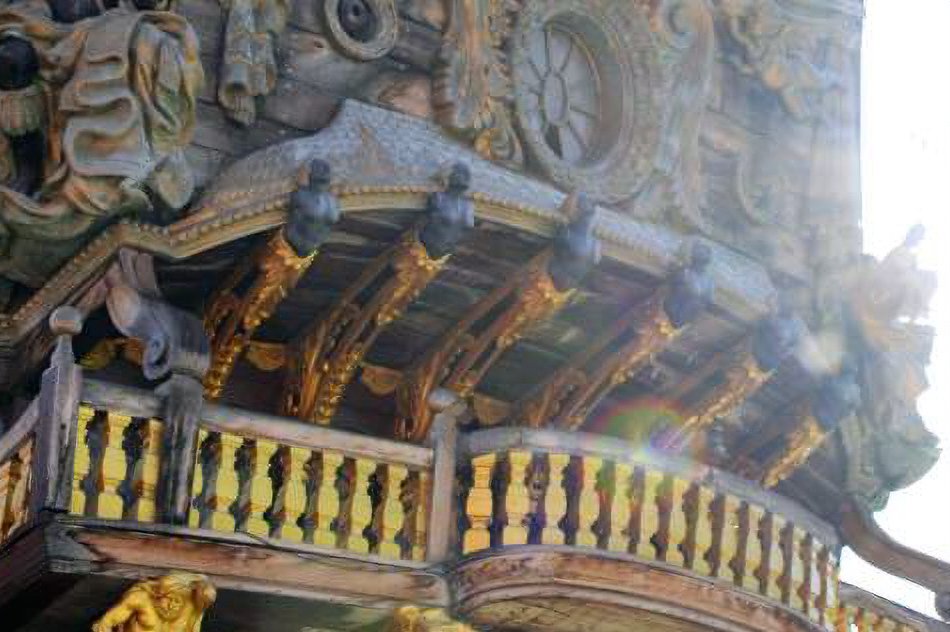
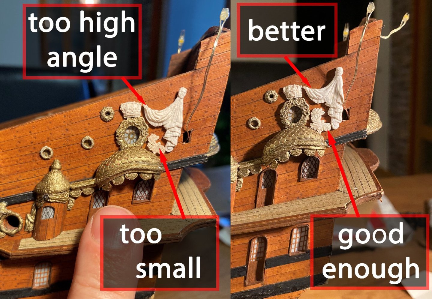
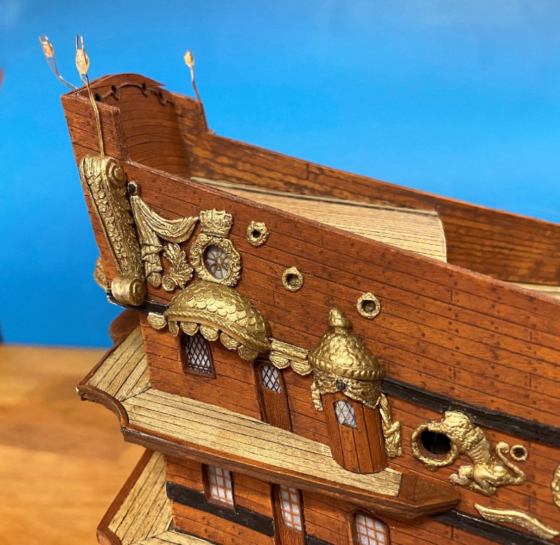
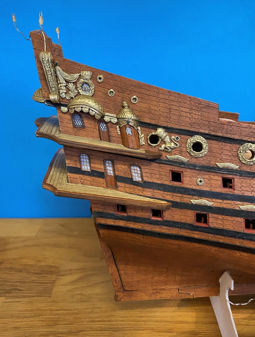
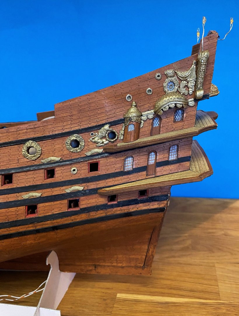
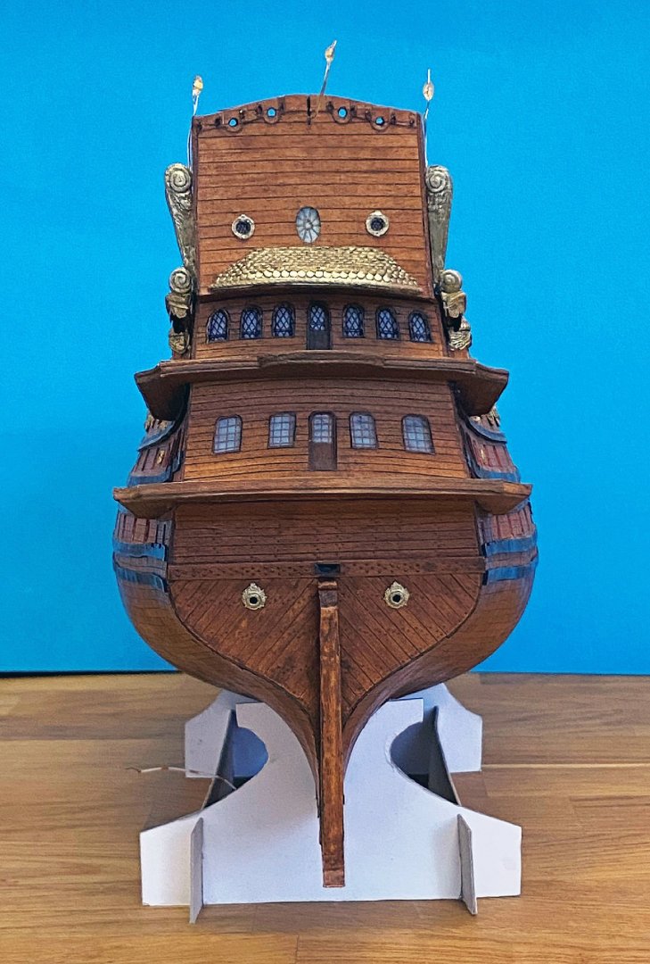
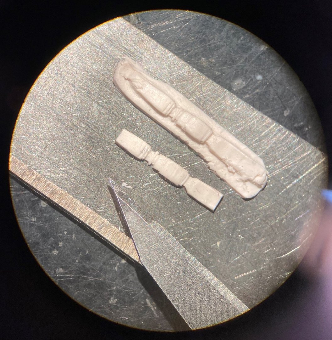
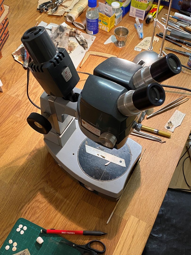
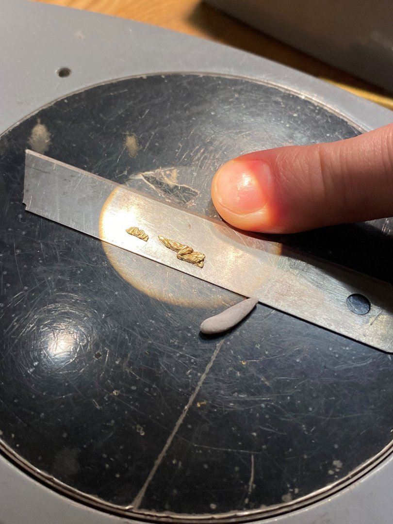
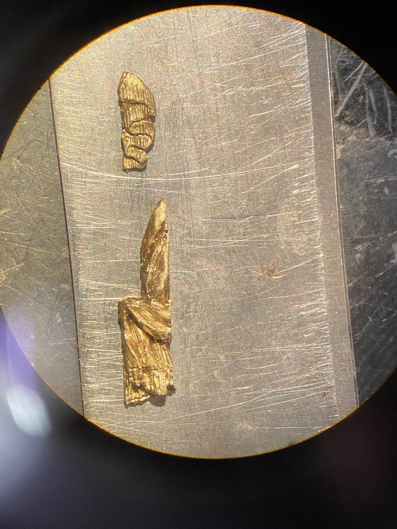
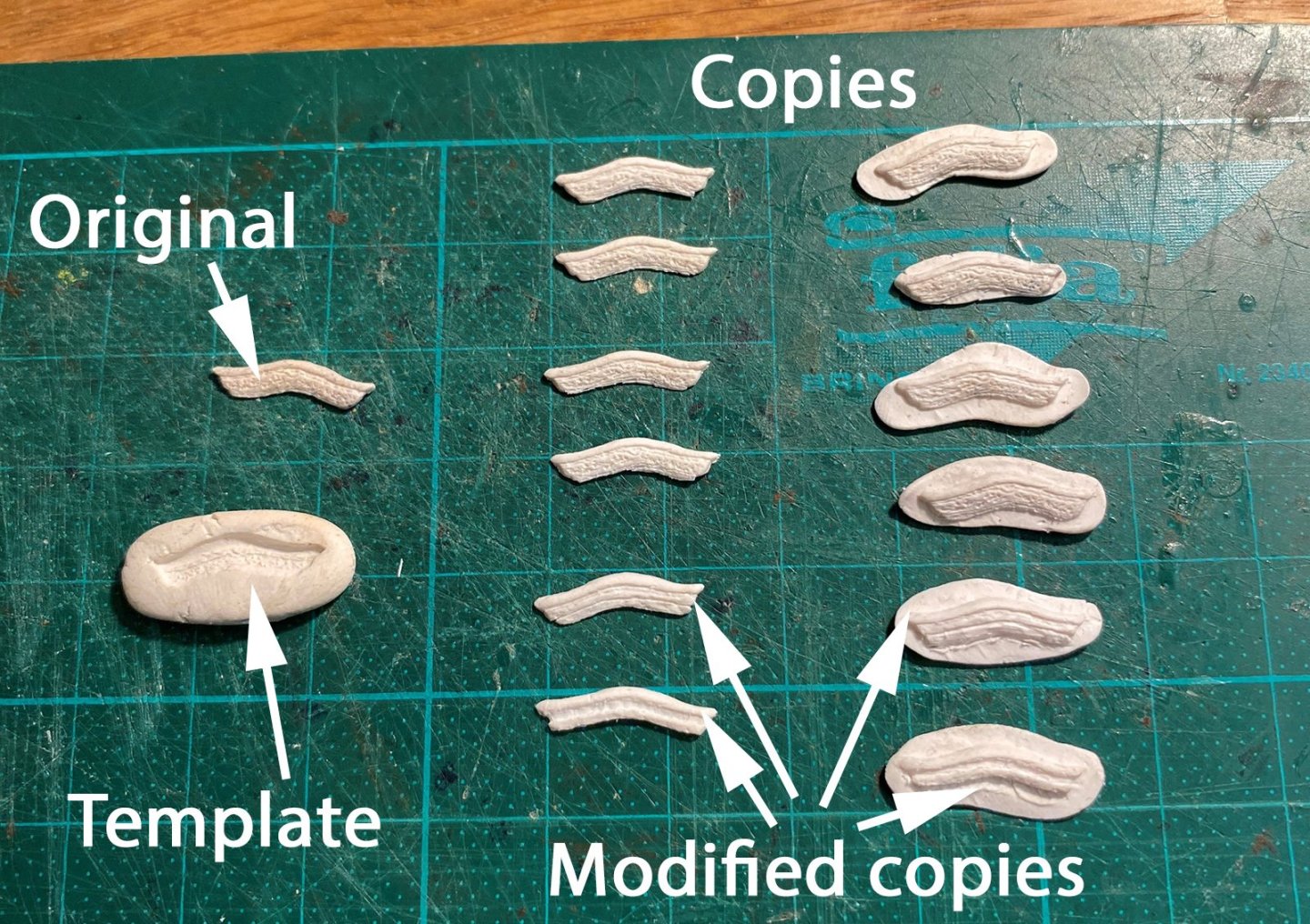
Hi there! The railings proved to be more complicated than I thought...such is the scratch builder's life... My cutting board looked at some point like a garbage bin... The balusters for the side railing looked too wrong to me, too diagonal against each other. So I decided to sculpt new ones, with a more fitting appearance. I am currently finishing the upper balcony railing, the rounded edge pieces are still missing. But meanwhile I decided to make some of the upper balcony support beams. They are nicely decorated with some leaf ornaments and some amazon warriors. 😮 My apologies for this picture, but I could not find any that would show the ornamentation of the beams any better... So after thinking a lot how I could make these details more or less "in scale", I decided to go with the clay and cut out the leaf ornaments as tiny as possible, again, using some templates and negative moulds. The beams themself were made from card (ca 2mm thick), the foil and some paint, finished with a clay sphere at the bottom. The amazon figurine I made from clay, trying to imitate the face also. It turned out to be really small... ....So small that I got curious as to how small the nose-imitation detail on it is. So I took the template with to work and looked with a digital microscope. With that we measure lengths, sizes and depths of surfaces (for those of you who are interested, it has also a LIBS attached - Laser Induced Breakdown Spectroscopy, a type of chemical analysis at the micrometer scale) . So my colleague made an image while I was holding it and measured the length of the nose: roughly 230 micrometers!! 😅 I do not think I can make any smaller details... For fun, a colleague suggested to model this figurine with tinkerCAD and he could try to print it out with our 3D printers for comparison if the printer can make it any better. Maybe I'll give it a go! 😄 In the end this all does not really matter, because these details are so small no one can see them anyway, especially after painting the figurines black! There is not enough shadow anymore to make the face visible...😅 Then I borrowed a better camera and tried some 'test-shots' a couple of days ago in the evening. Here are the rather dark results: So much for now. I am continuing with the railing and will do some of the ornamentation for the stern, before continuing with the lower balcony. Ahoy! -Radek


-
Ab, another nice type model of yours. The Van de Velde sketches are awesome! I imagine he must have been either fast making them as the boats and ships pass by (I live at the water front here and in the summer enjoy watching the passing by sailboats of the local residents), or there were just so plentiful he could take his time. How do you get one of those sketches?? -Radek
-
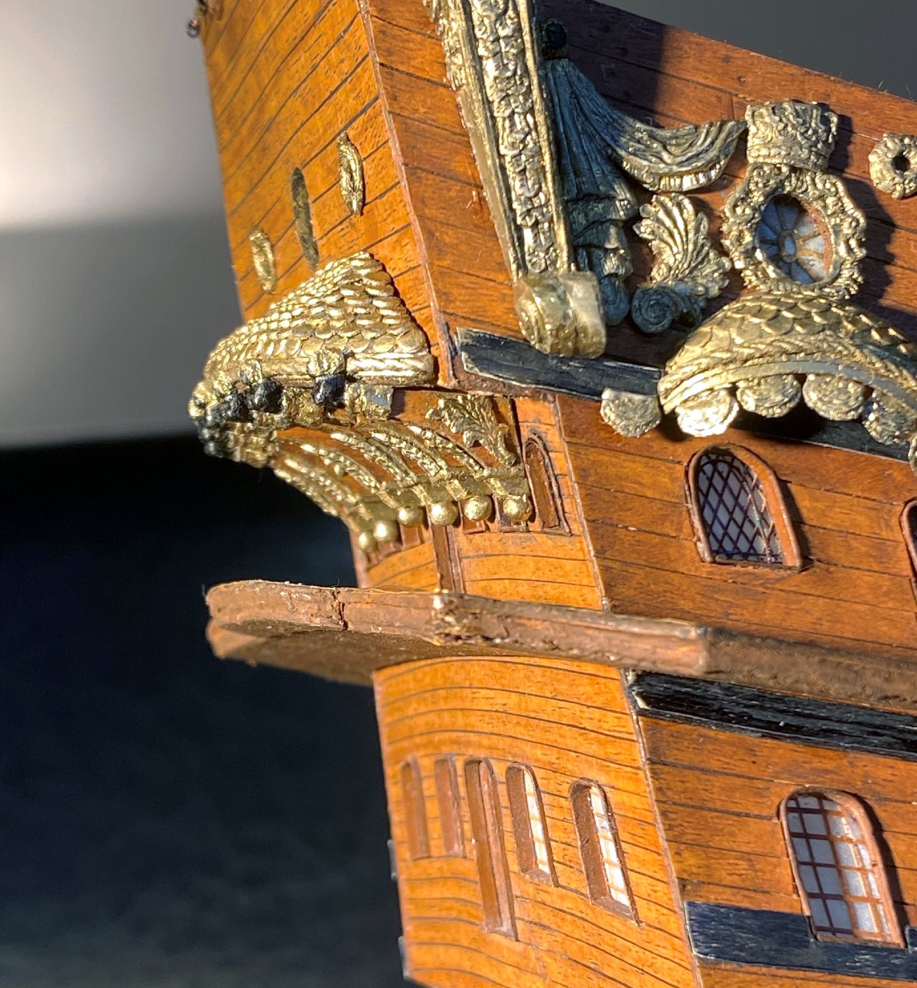
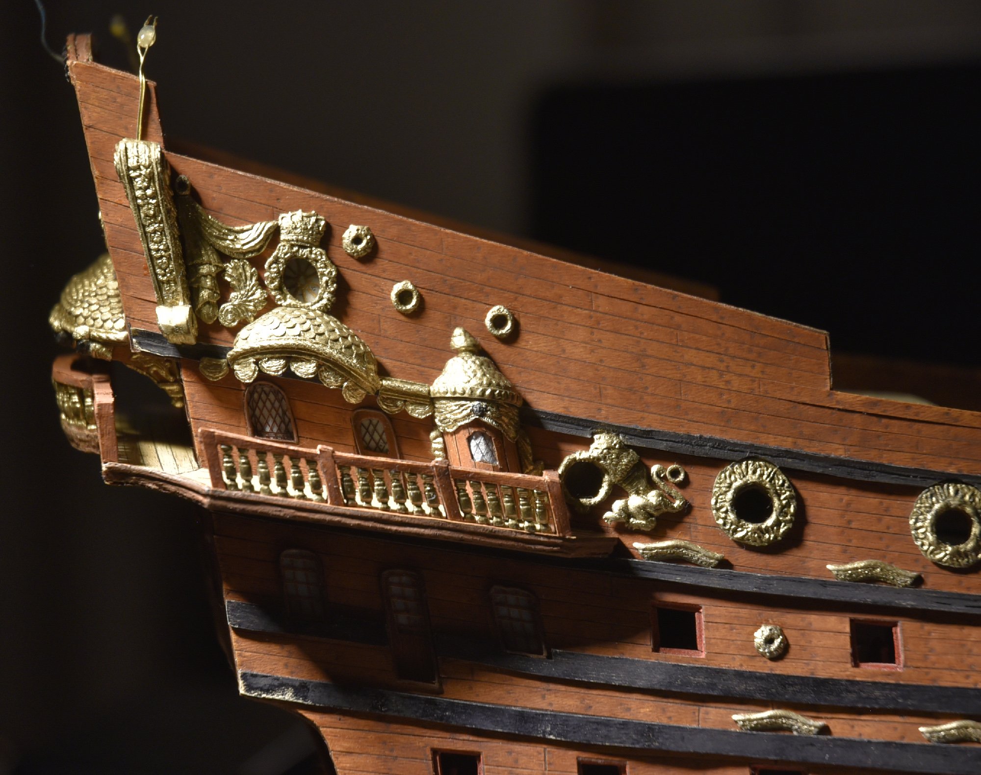
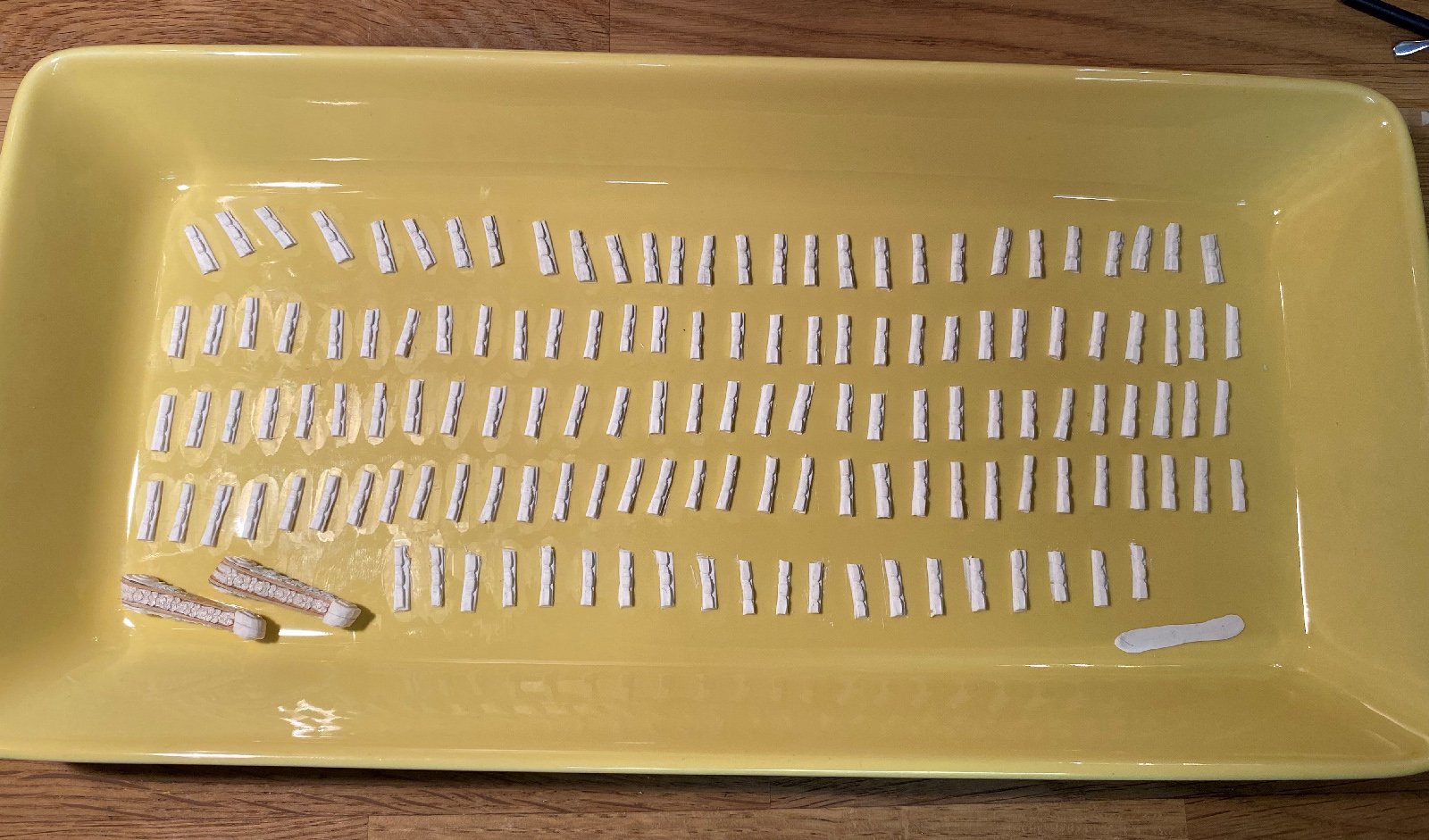
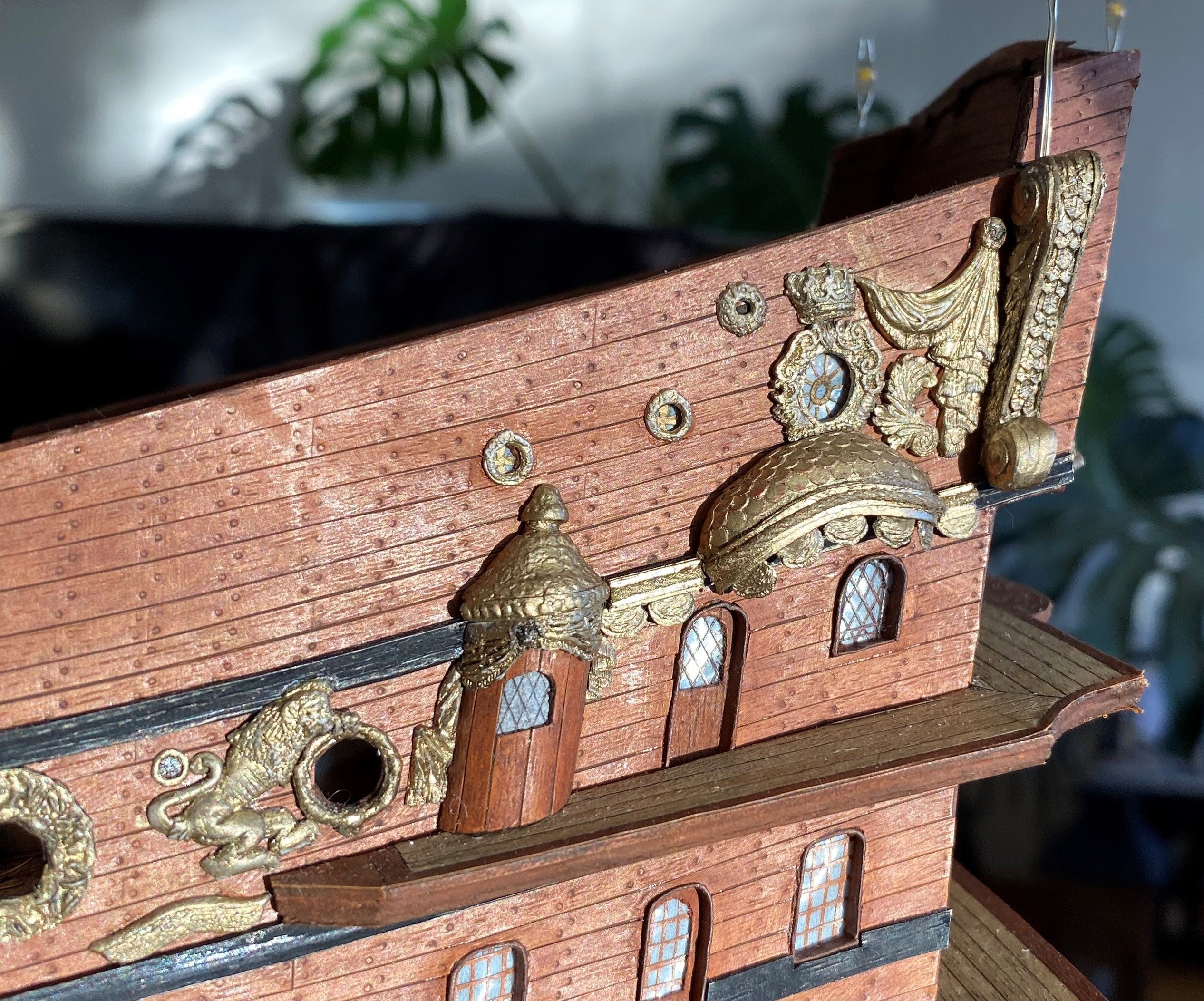
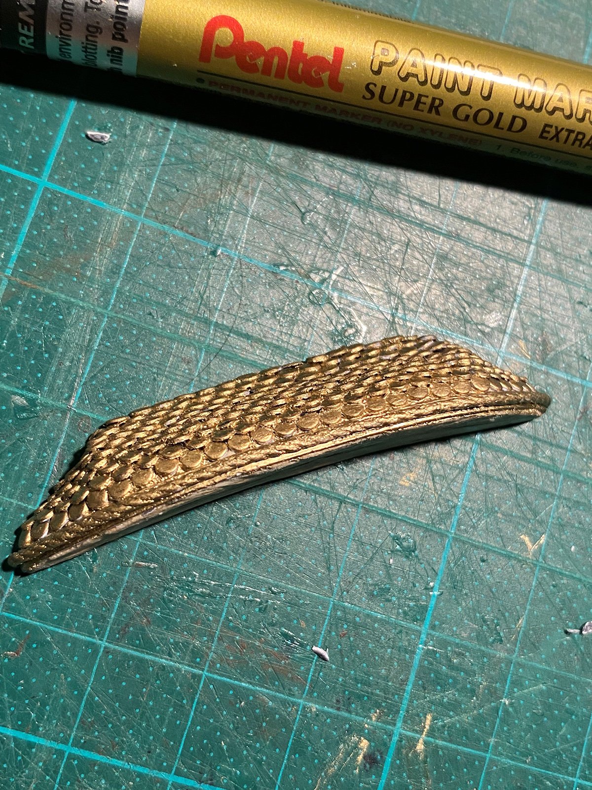
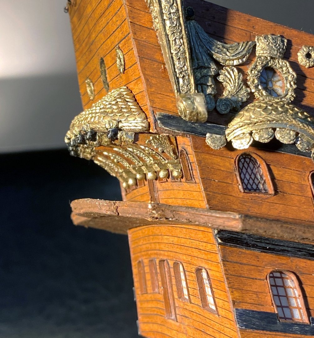
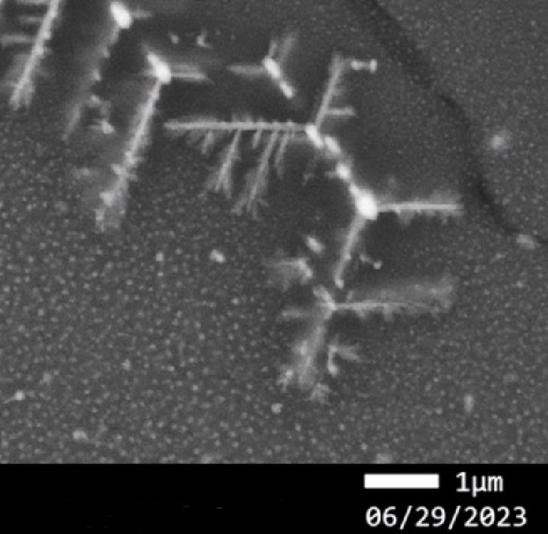
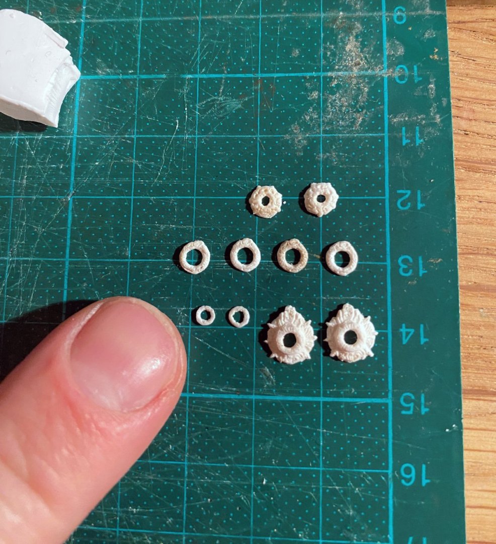
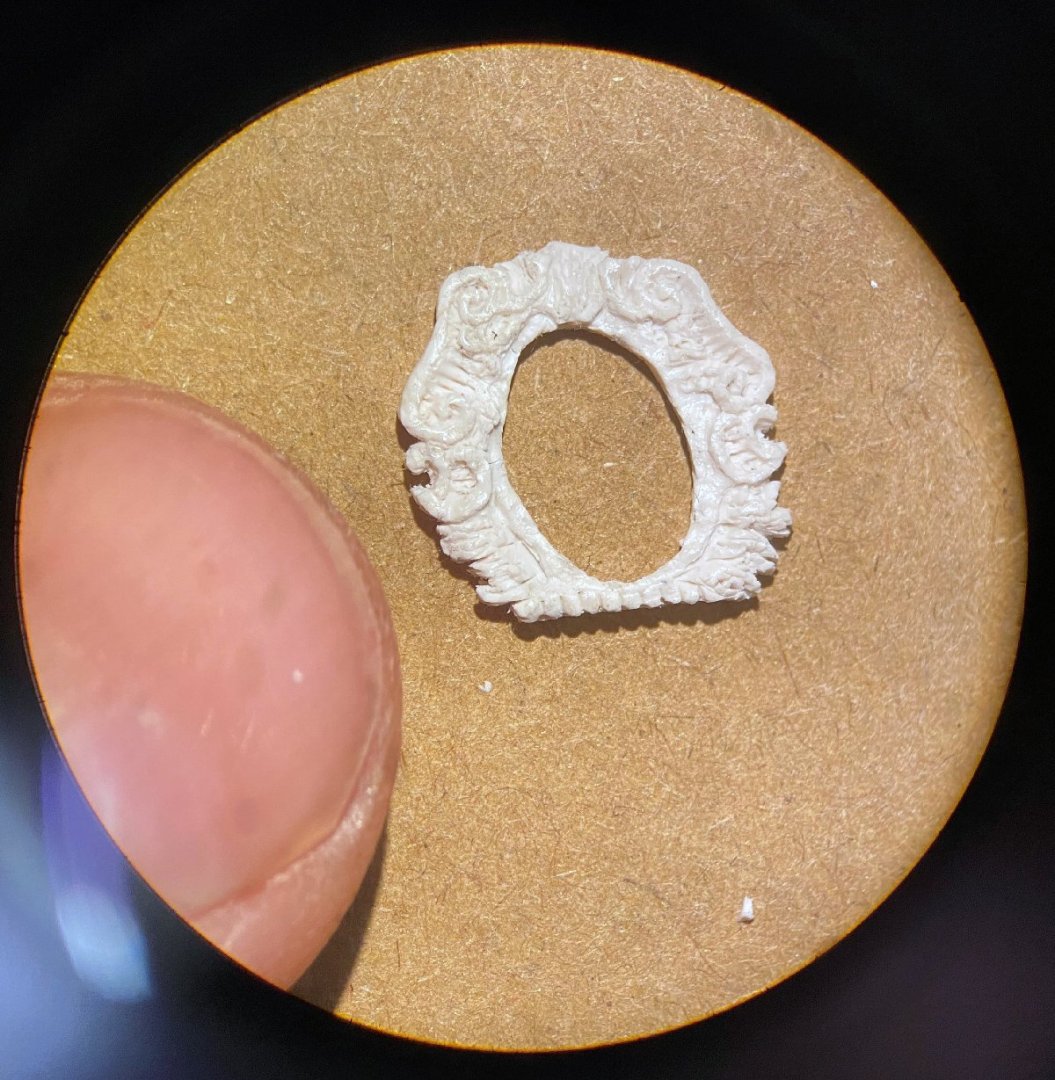
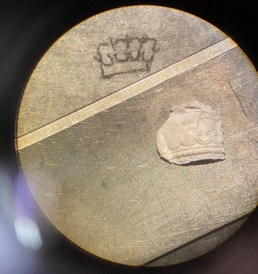
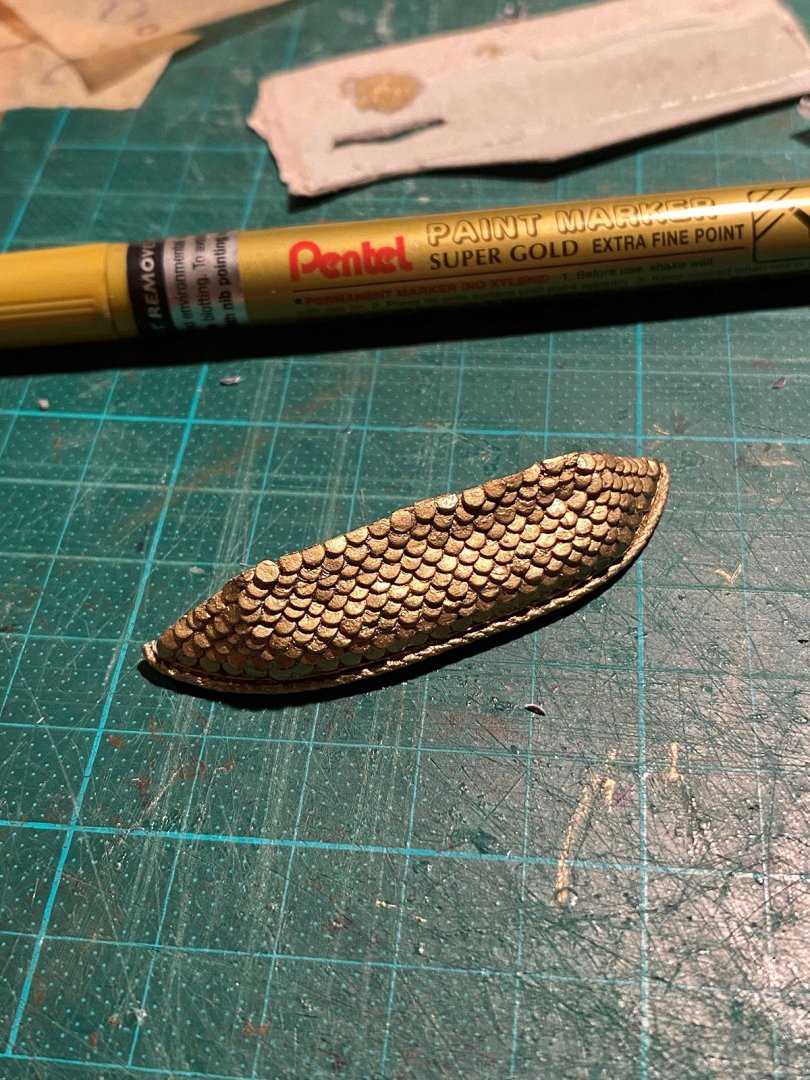
Hi Chris, It all depends a bit on which scale you use. Maybe in 1:75 I would not need the stereo microscope. But unfortunately there is not much space in our small appartment so 1:100 must suffice 😊 At my workplace I am working with an electron microscope/microprobe, where I can see even in the nanometer scale 😅 Here an example of a so called dendritic crystal growth structure of an Fe-Ti-oxide (bright branches) in silica glass (dark grey with brighter spots) from a volcanic rock: But back to the topic on hand: The pirate-Galleone Neptune Thank you all for the likes ☺️ The wash cant made me some troubles, because as mentioned, I used only three layers of card for the starboard one, which of course turned out to be too little...The eye deceived me and only after glueing it to the model I realized the assymetry. So I had to add still one small piece. Then I made some ring ornaments from the clay, using a template again. Here are some of them: The balcony has some side roofs. I tried to figure out how to make the roof tiles, since they look a bit smaller than the ones on the back side roof. But I ended up using the same method as before but this time I stamped out the round tiles from a thinner card. The big roof part itself is made this time from the clay and the decoration on it from card and a thread. The tiles for the roof on the towers I imitated with glue-drops. I continued with the decorations around the window: I use a point needle and a sculpting tool as well as the scalpel mainly when working with the clay. Crown work in progress: A drawing alone seems not enough to make the clay ornamentation correctly. It is difficult to estimate the scale under the stereo microscope without a scale bar, so I made some parts too small, others were too large or not bend in the right way and I had to do them again. Lesson learned: I will draw a template on card first, see how it fits onto the ship, and use that as a scale for the clay sculpting. I made the lantern posts also by first making a few templates to get the angles right and then I used a bit of clay to make/imitate the ornaments on it. And this is the ship in its current state: My apologies for the not so good images. They were made with my phone camera only. 🙄 And the lightning is not the best at the moment in Finland... Here one last picture in rare natural sunlight: 😅 Currently I am working on the railing for the upper balcony. For that I again make a template for the baluster. But since it is only half of it, I need to make twice as many (I made 180 to get altogether 90 balusters), then I cut them out and glue together... Ready baked balusters and the lantern posts... So much for now. See you all around next year! Rgds, Radek


-
HMS RESOLUTION 1667 by KarenM - 1:48
RdK replied to KarenM's topic in - Build logs for subjects built 1501 - 1750
This looks really clean and very professional. Rgds, Radek -
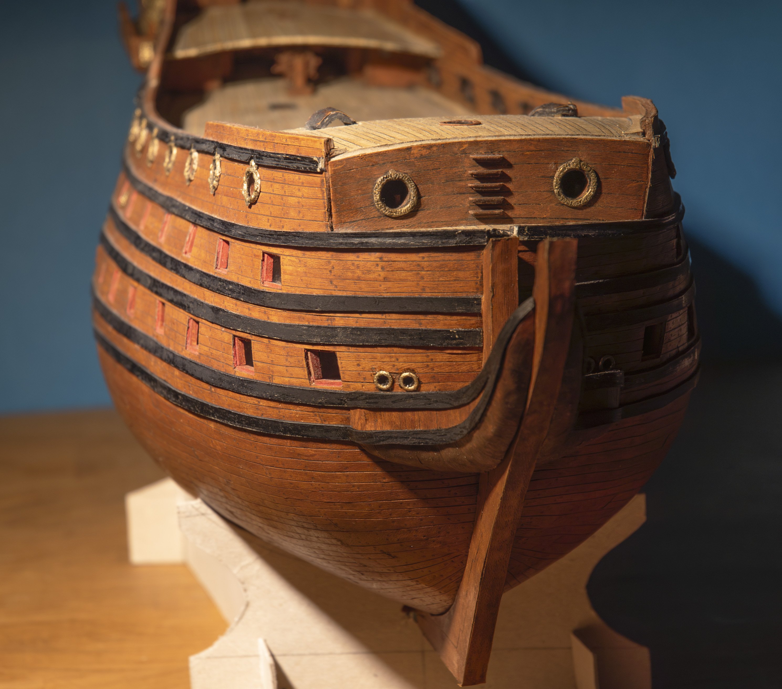
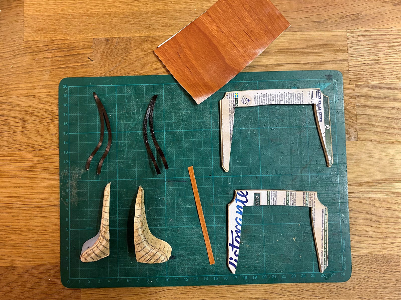
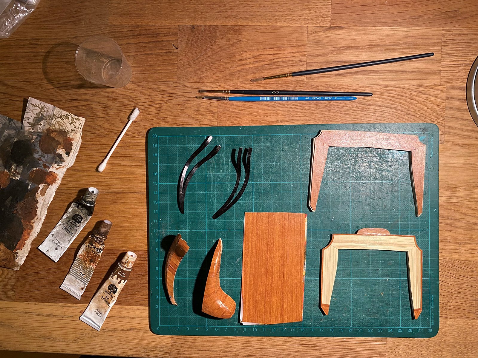
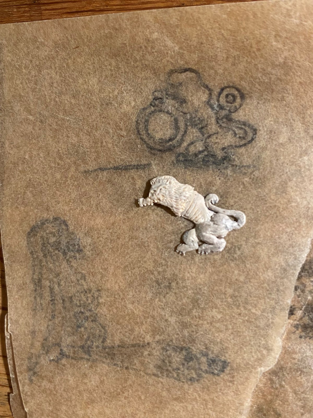
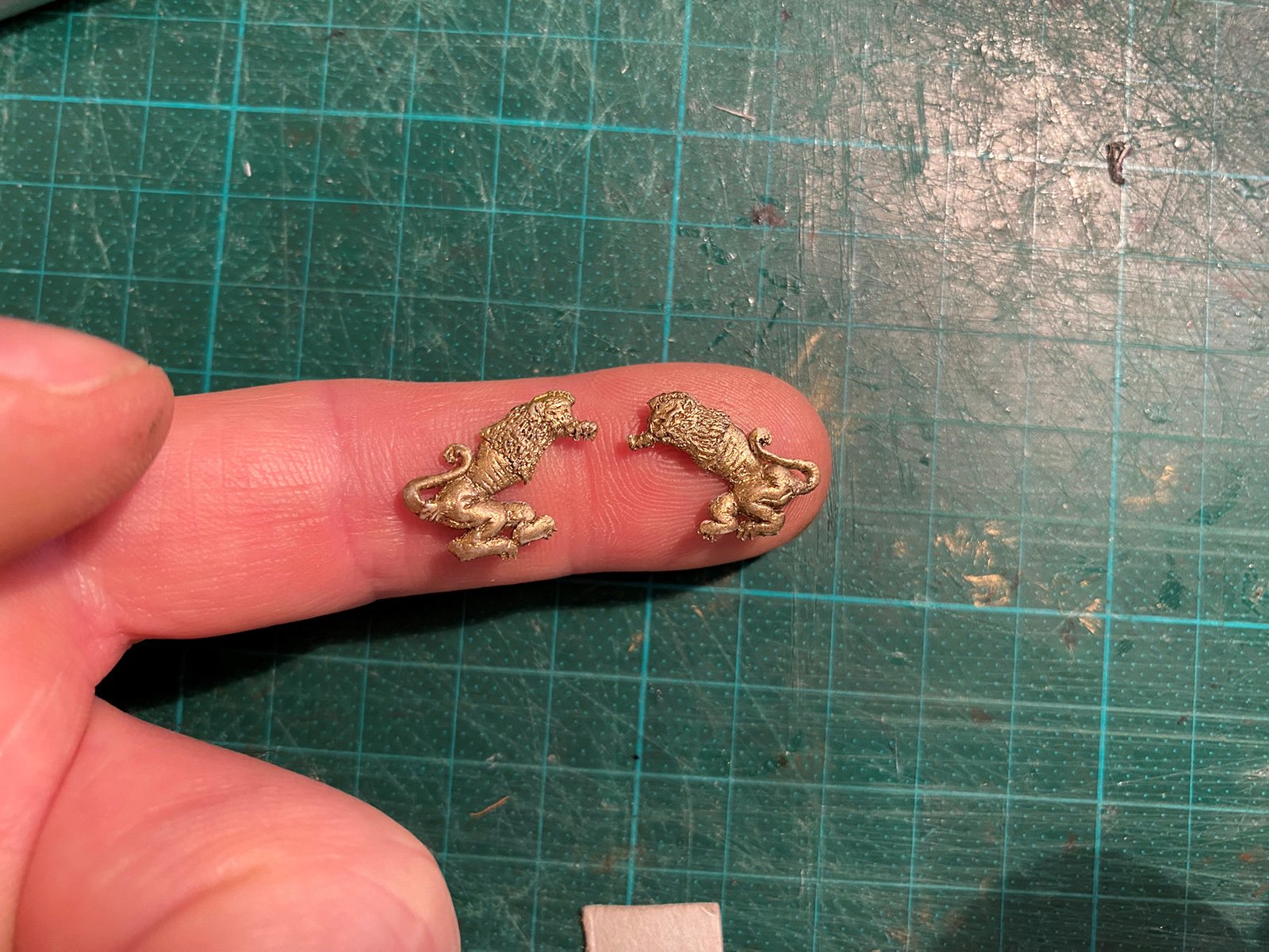
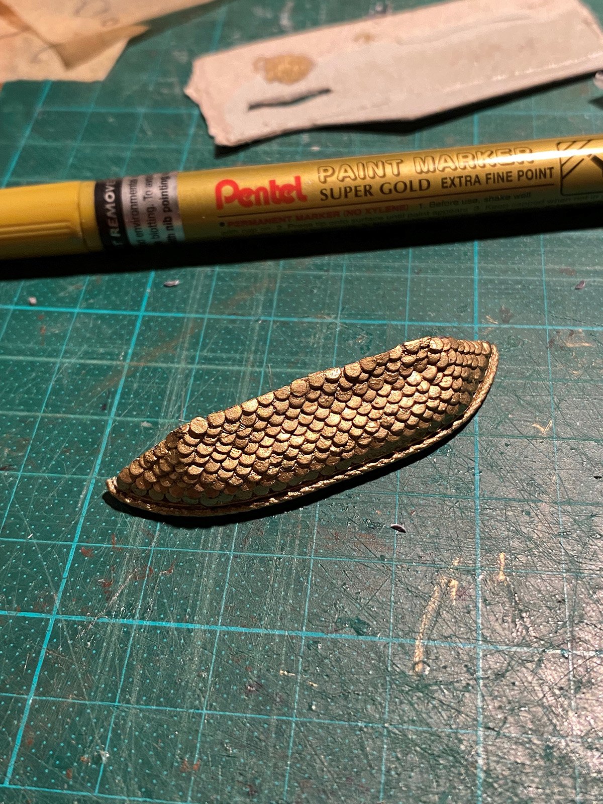
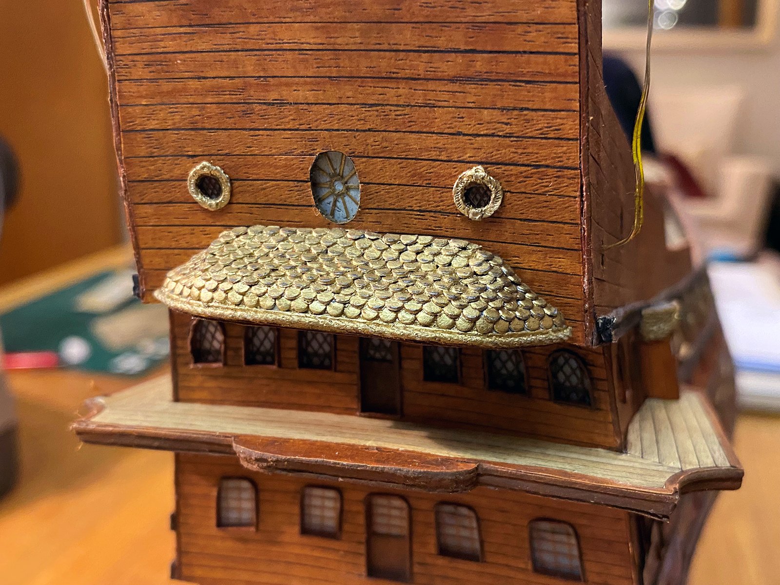
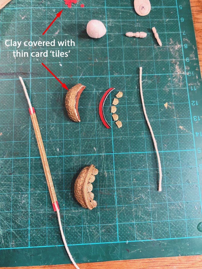
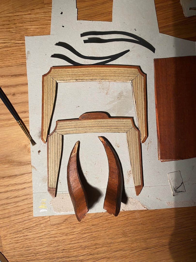
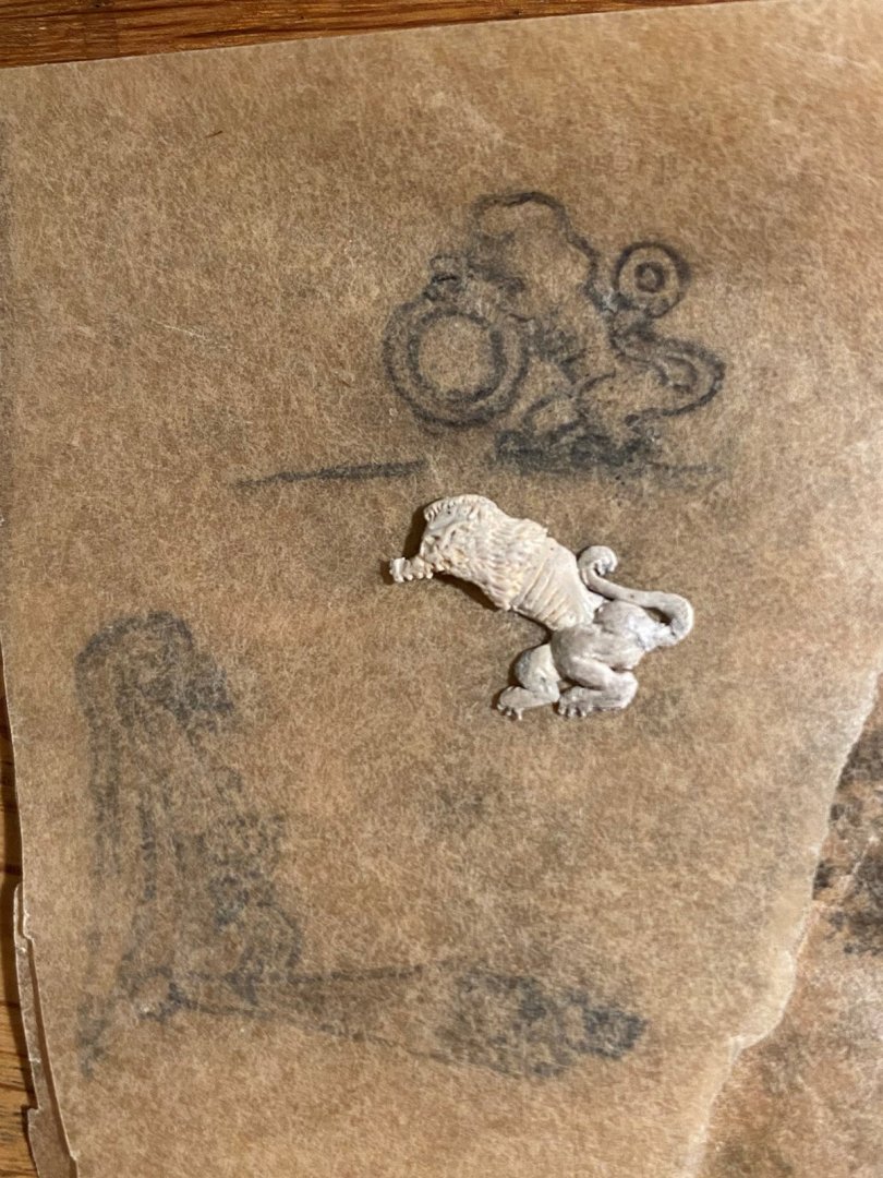
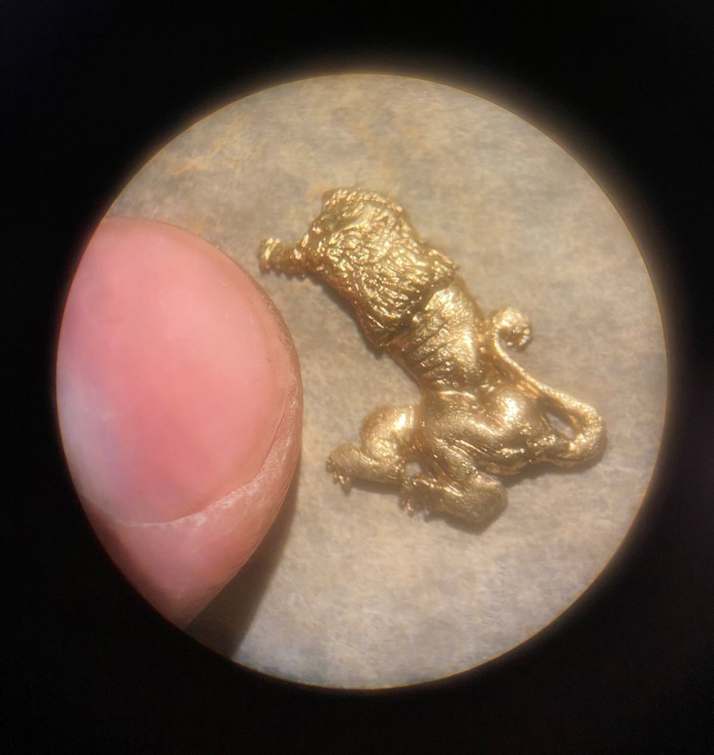
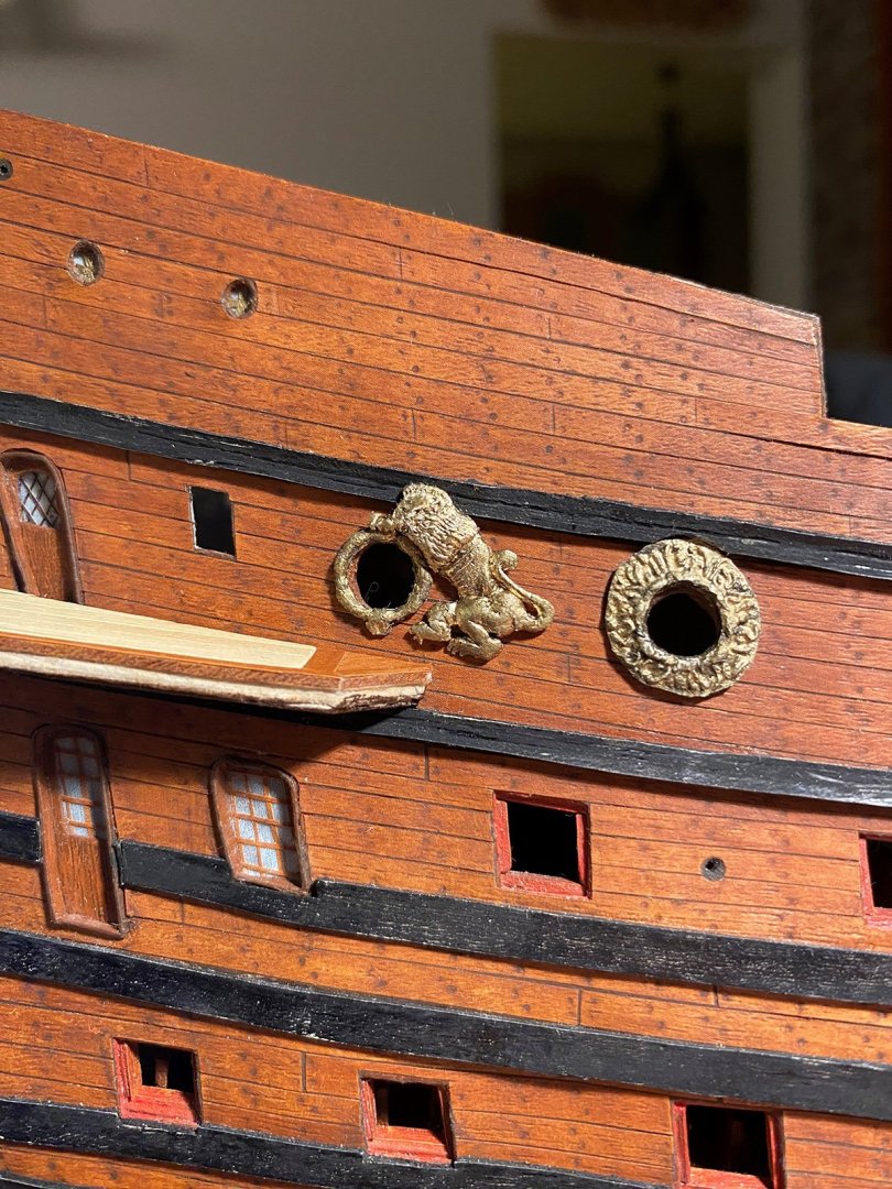
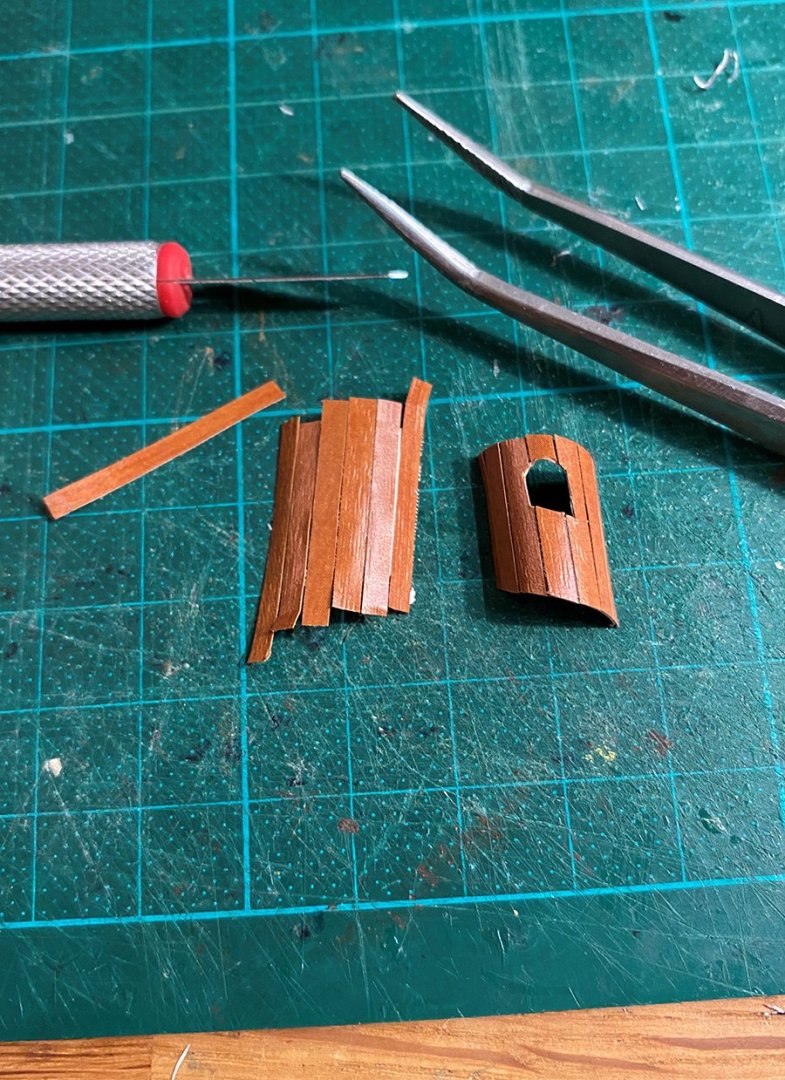
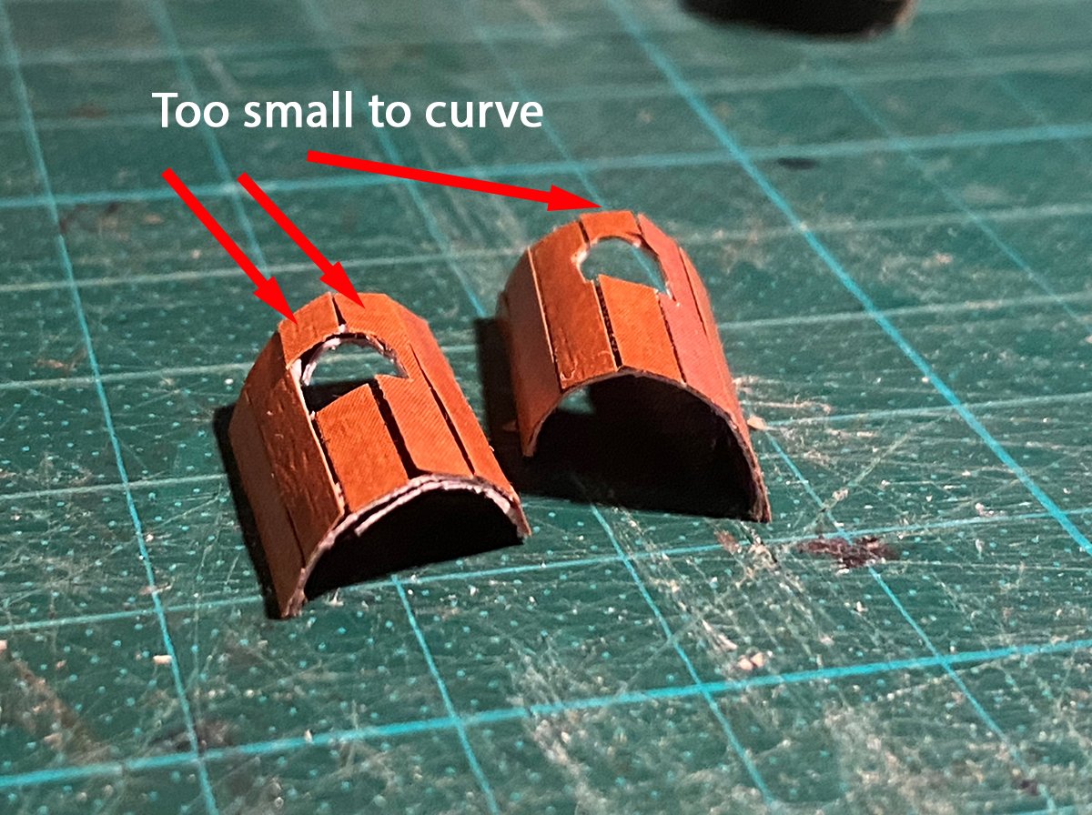
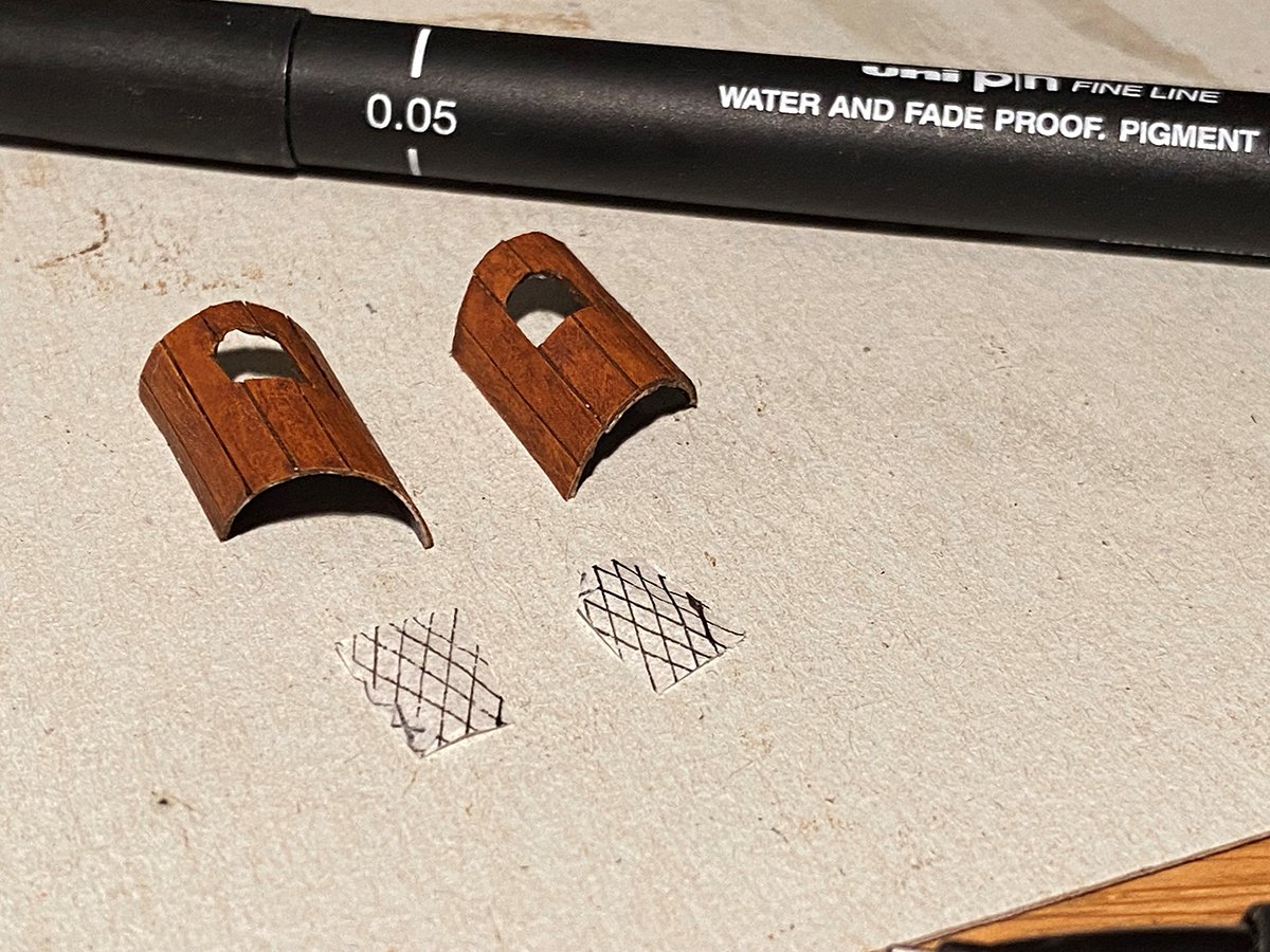
Hi there everyone, The wash cant and the cheek fillers got a "blocky" plank appearance after looking at several contemporary models I've seen here and there. If you have a good idea how they should be planked, please let me know, I am always keen on learning more. The balconies got their planking as well and then I altered with burned umber brown and black oil paint. While the parts were drying (and oil paint needs a while to dry...) I attempted some model clay figurine shaping based on what I learned from DORIS. 😊 These two buddies are supposed to be lions 😅 They are about 1.5cm high. The scale I chose for this model is not very convenient for modeling/sculpting small sculptures, but it is all a "try out" for me to see what is possible and what not. I use a stereomicroscope to model in such small scale, otherwise I would not see anything... I also made the rounded shape on the sides of the upper balcony and am currently trying to sculpt the golden ornaments above and around it. The foil did not want to curve at this small scale so I had to apply a bit of CA glue to fix it in place. Then I altered with oil paint (burned umber) and the windows were made this time not from mini-grip foil but from tiny paper like baking-paper (I think I got it from some shoes I bought as packing material) and I drew the frames with a 0.05mm tiny black marker. The back roof of the upper balcony was made from several 2mm thick cards glued together and sculpted into shape with a scalpel. Then I used the method Jan is using for his beautiful Sovereign of the Seas, which is also a common technique in paper modeling, by cutting out small circles from card and glued it to the roof as 'roof-tiles'. For the lower stripe ornament I used a thread glued to a stripe of card. I am continuing with sculpting different ornaments and I use 'templates' when I need to make several same-looking parts. I still work on my painting skills using a gold-marker but I try to get somehow some darker shades into the grooves... More will follow soon. Rgds, Radek


-
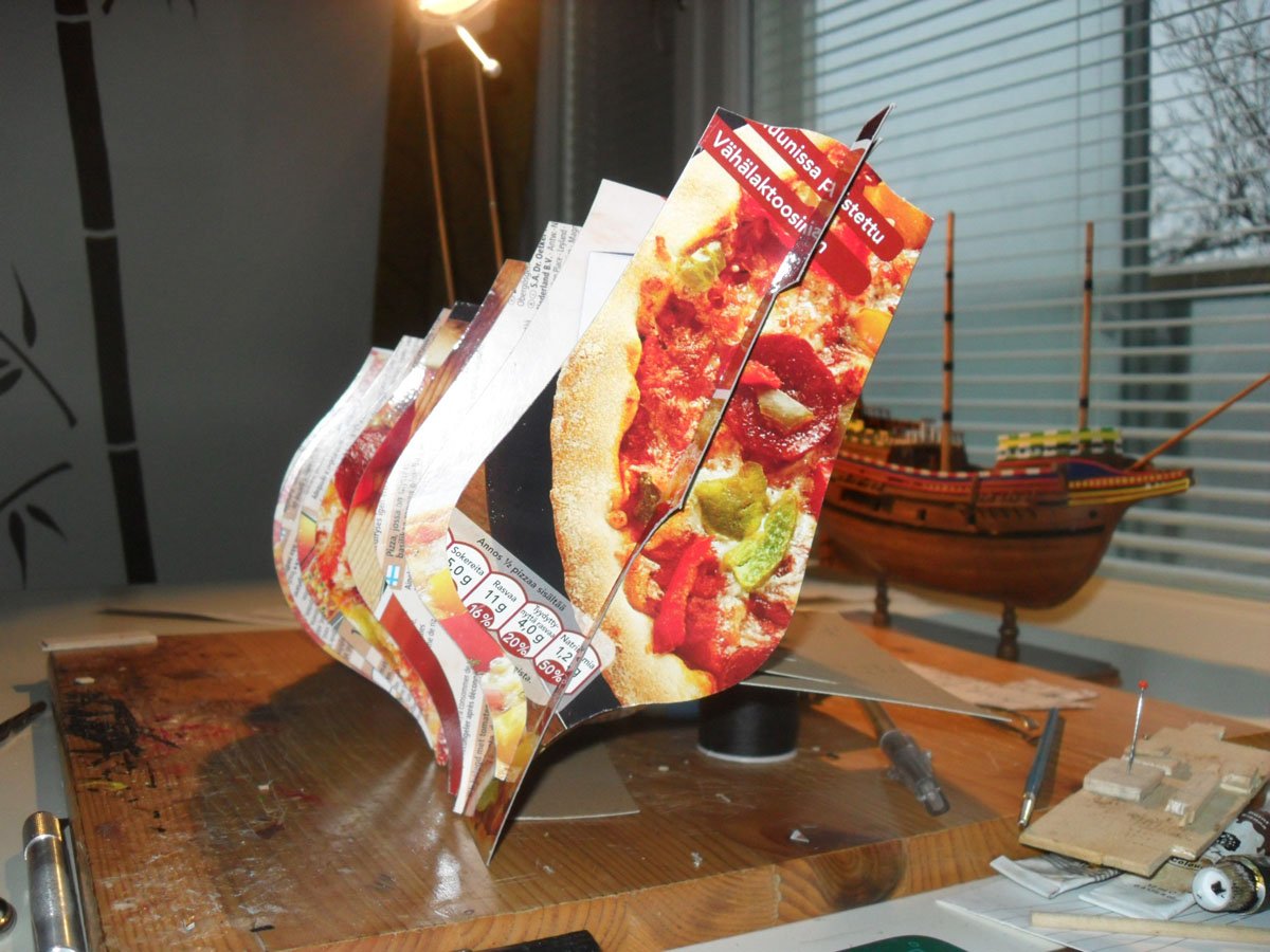
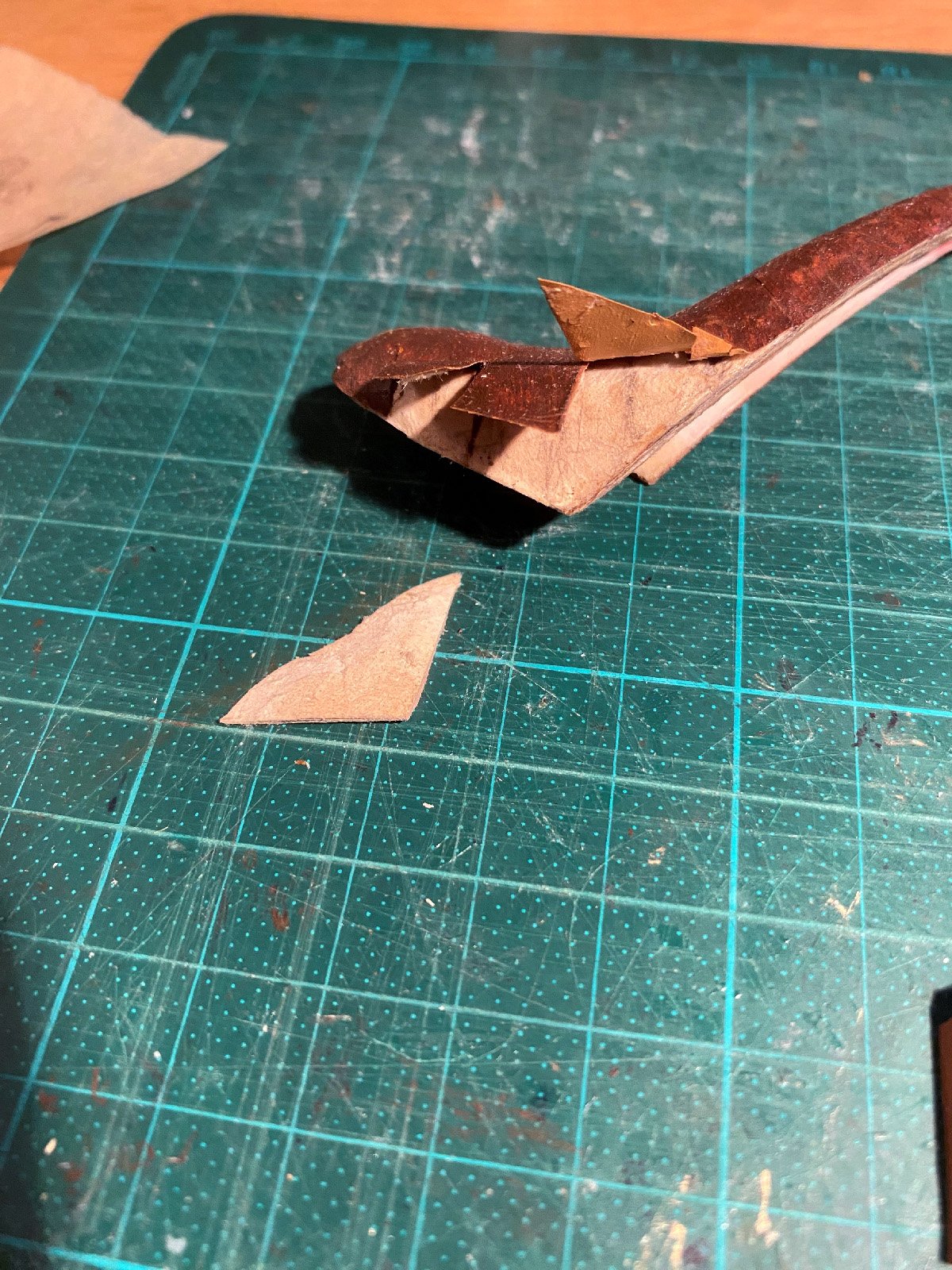
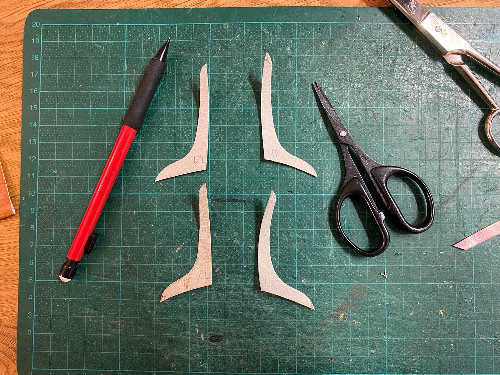
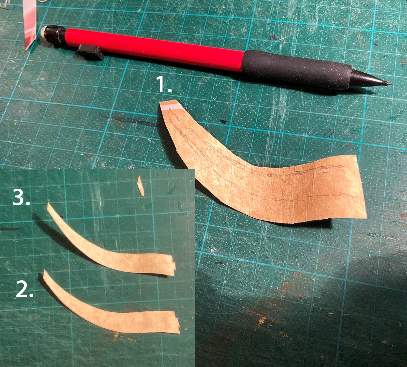
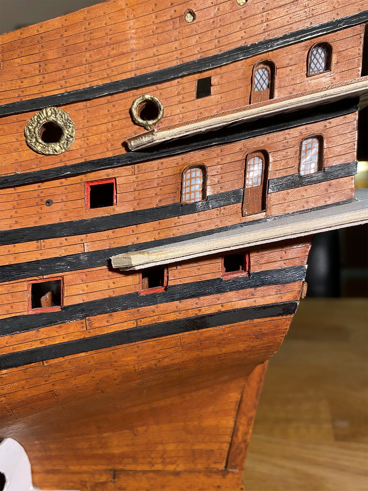
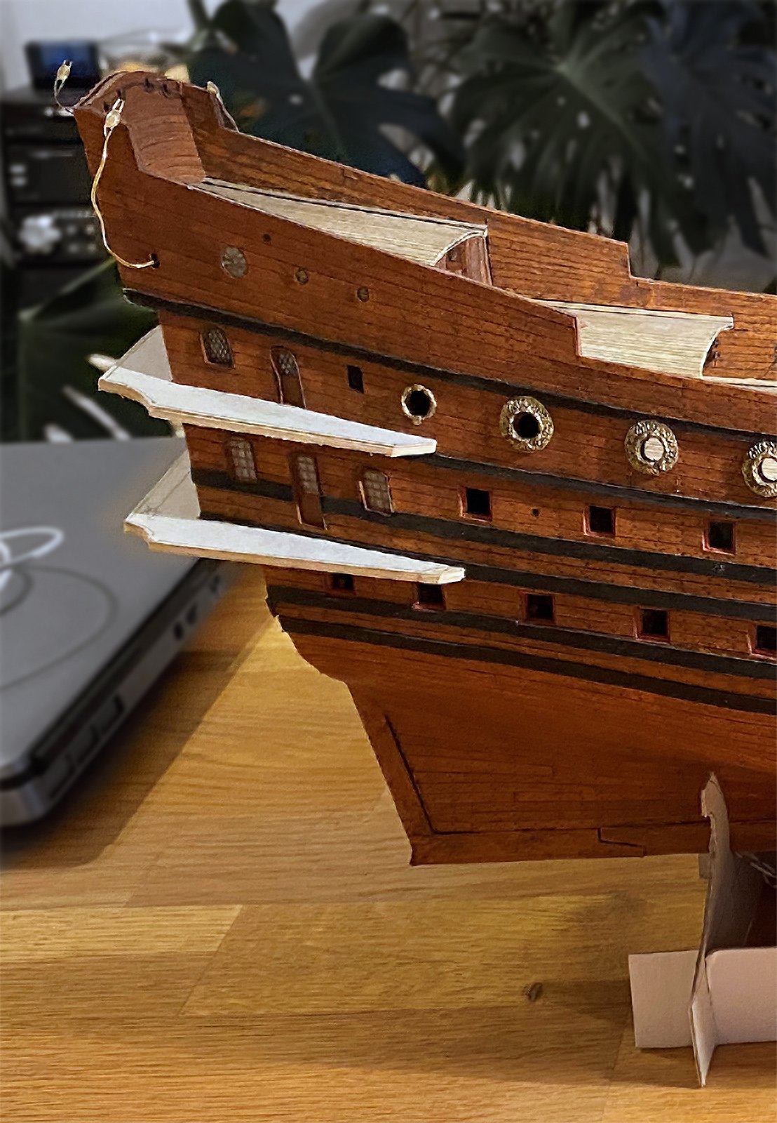
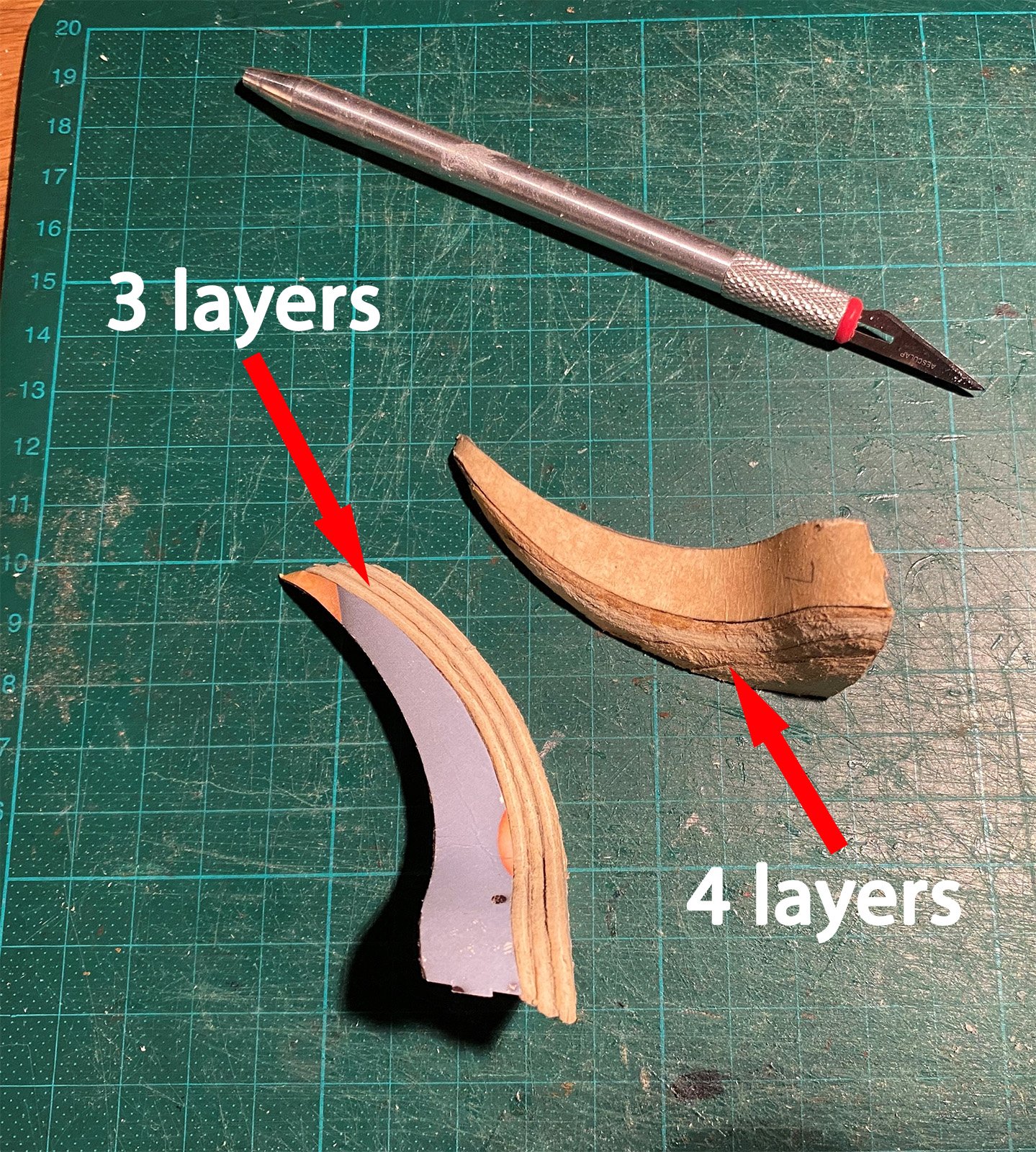
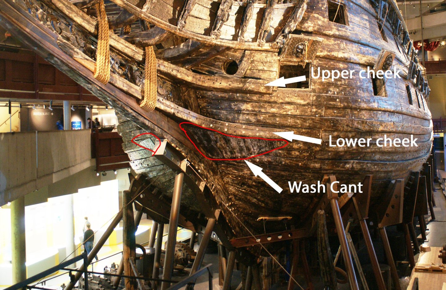
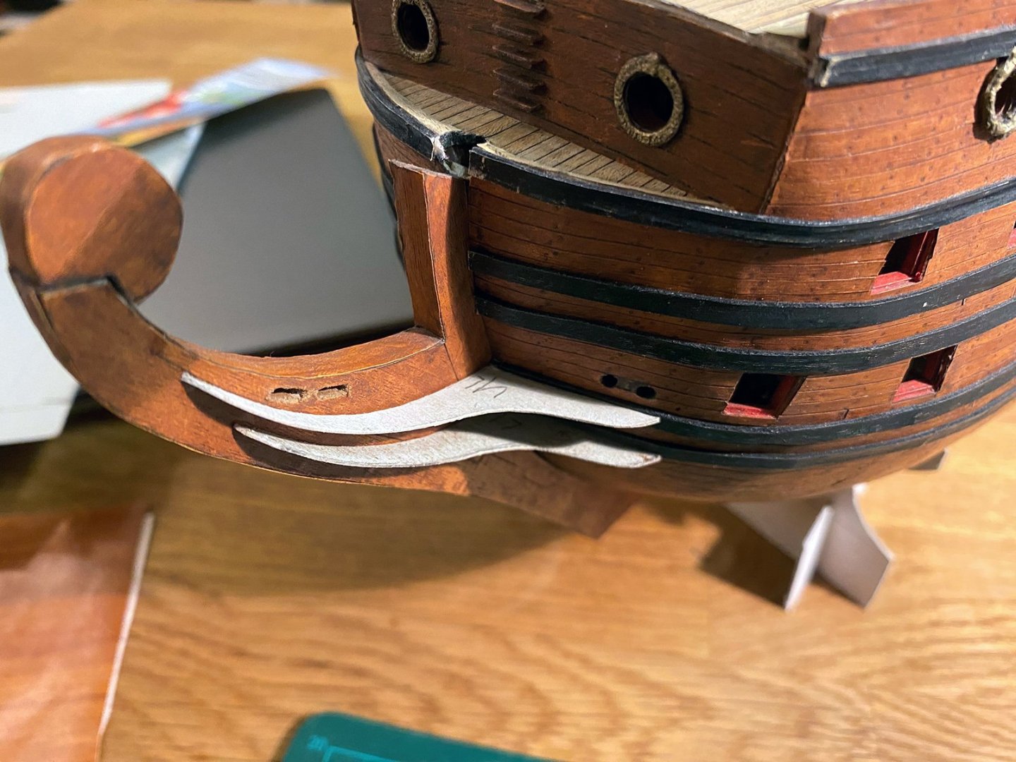
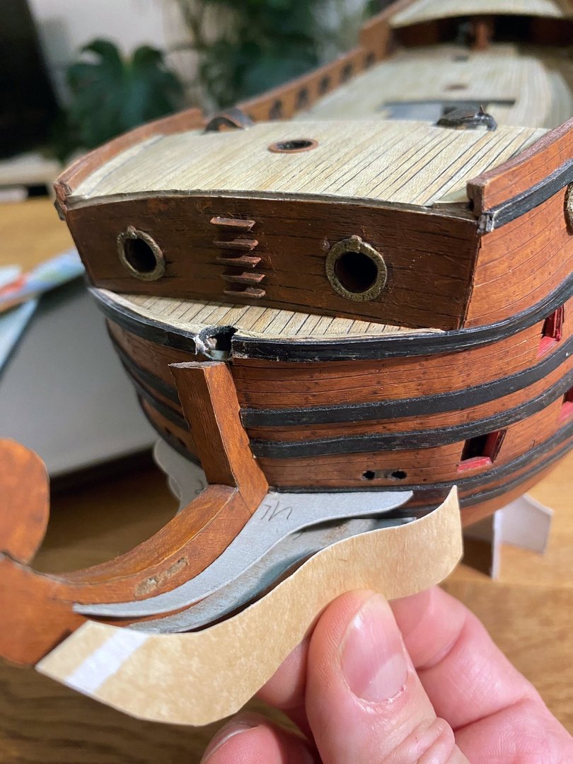
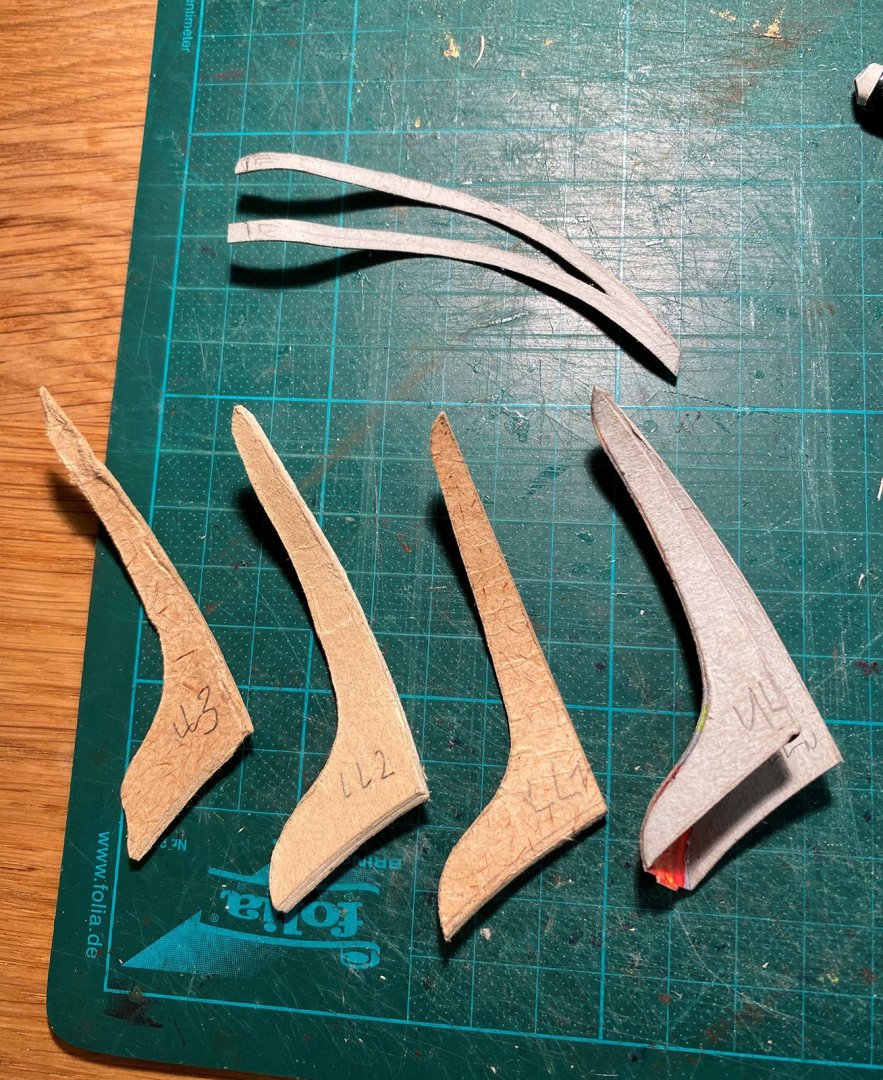
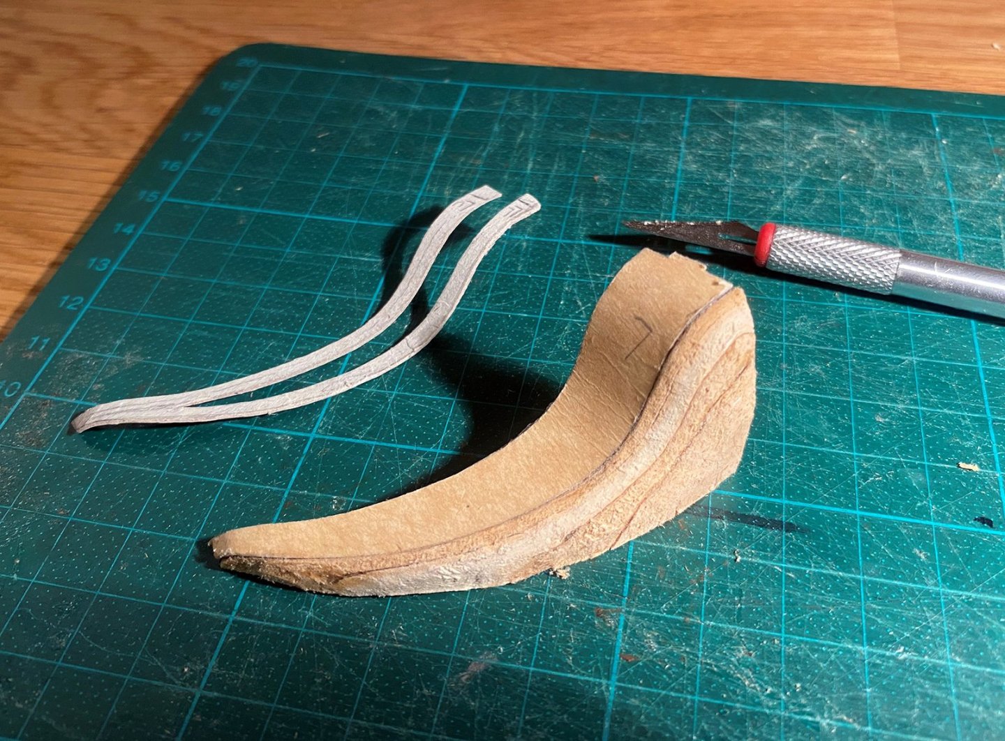
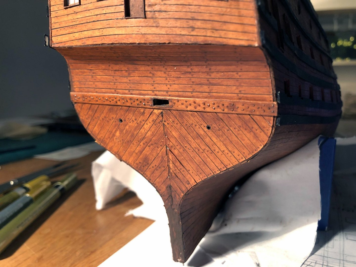
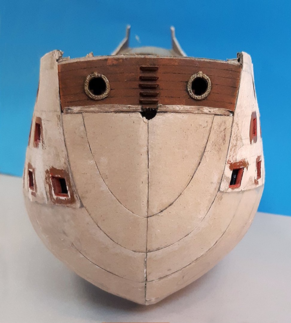
Hello everyone, My apologies for being (again) absent for such a long time, but life's realities catched up with me and as I slowly get older, injuries happen... I had a slipped disk in my neck a bit over a year ago, leaving me with chronical pain in the neck, shoulder and right arm. So a break in all my hobby activities was an unfortunate must. But I am determined to continue this year on the Neptune. I left off at glueing the keel to the hull and preparing the balconies. I used several layers of card to make the balconies thick enough - two pizza card layers, one top, and one bottom slightly smaller (both about 1mm thick) and one thicker card about 2mm thick. But more on the balconies in the next post. In this small update I started to make the cheeks and the wash cant at the bow. First I made a template from pizza card for the cheeks. Once I was happy with it I glued it temporarily to the hull to make a template for the 'filler' between the upper and the lower cheek. It took me several attempts to make the template correct. This part was made from a slightly thinner card (nevertheless also pizza card :D) Then I made the wash cant from three (starboard) and four (larboard) about 2mm thick card layers and after glueing them I cut them in its round shape with the scalpel. Comparing th the wash cant of the VASA my look more like from the 18th century, but after all this is a fantasy ship and I take my 'historical accuracy' freedom here and there... Next I will apply the adhesive foil and alter with oil paint to make it look like wood and glue to the ship. I just need to figure out what sort of wooden planking pattern I will use on the cheek-filler and the wash cant. The VASA wash cant looks quite 'simple', compared to the curvature on my one... I will also apply the foil on the balcony, after which I will make the railings and start my attempts at making the decoration figurines for the stern from the baking clay. Thank you all for your patience and bearing with me on this long journey! Rgds, Radek


-
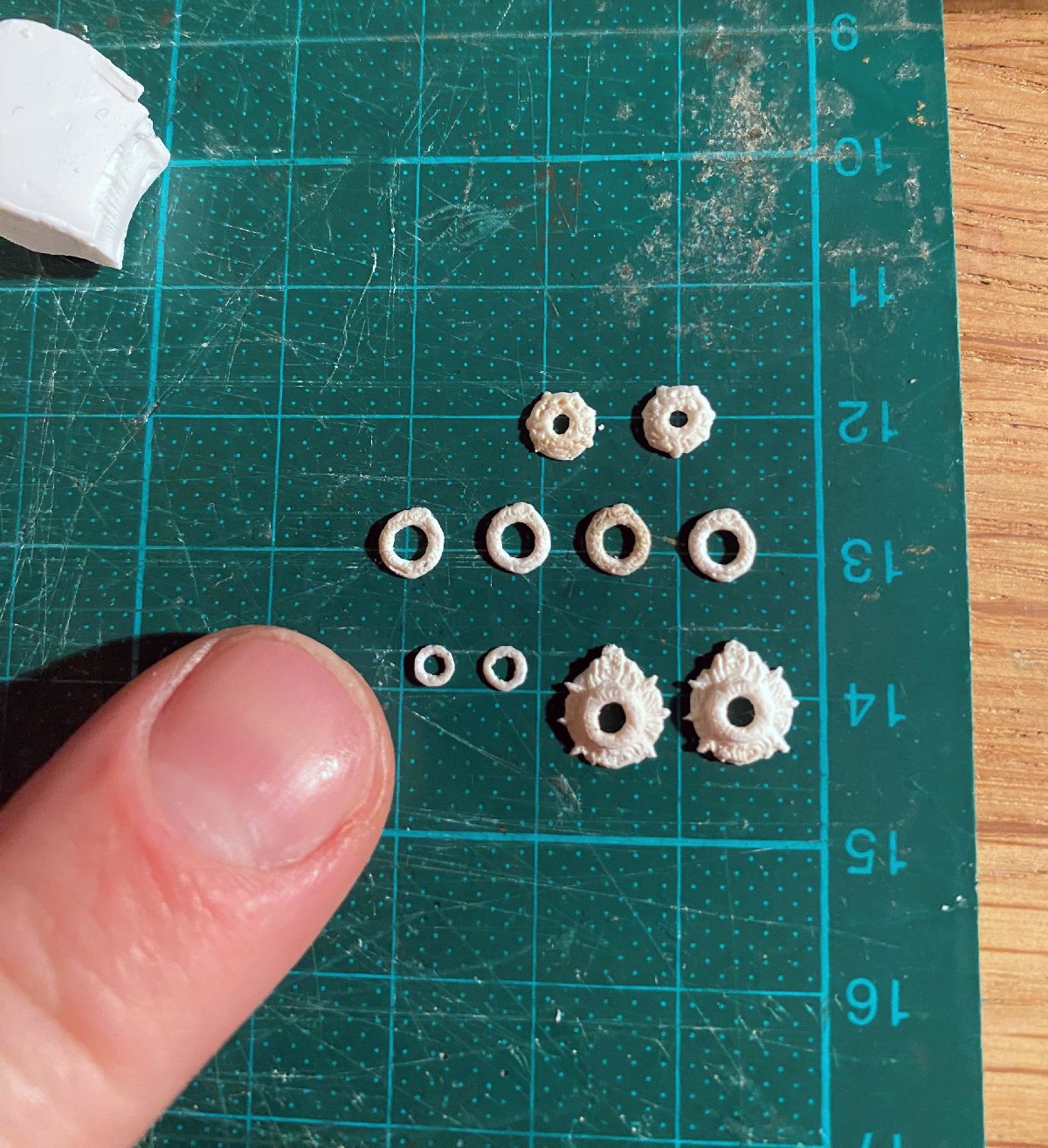
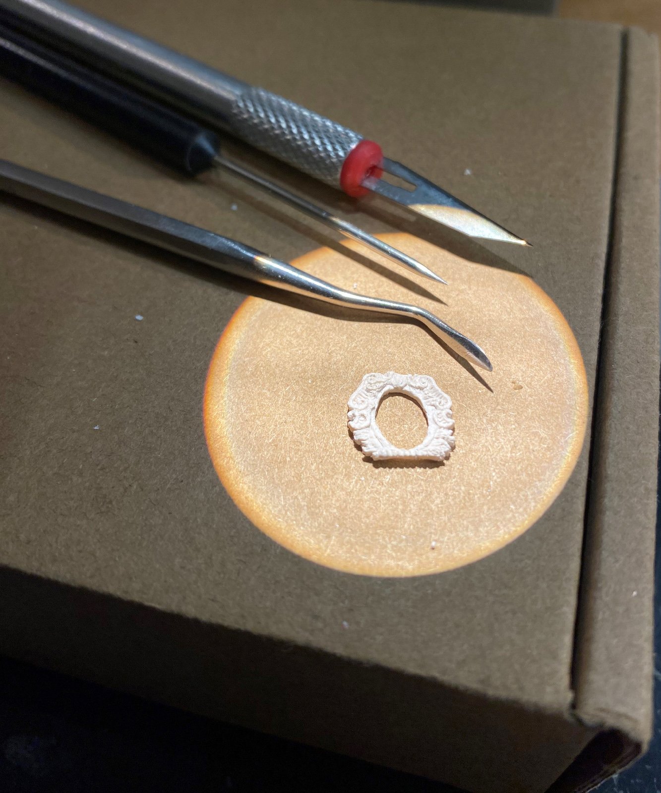
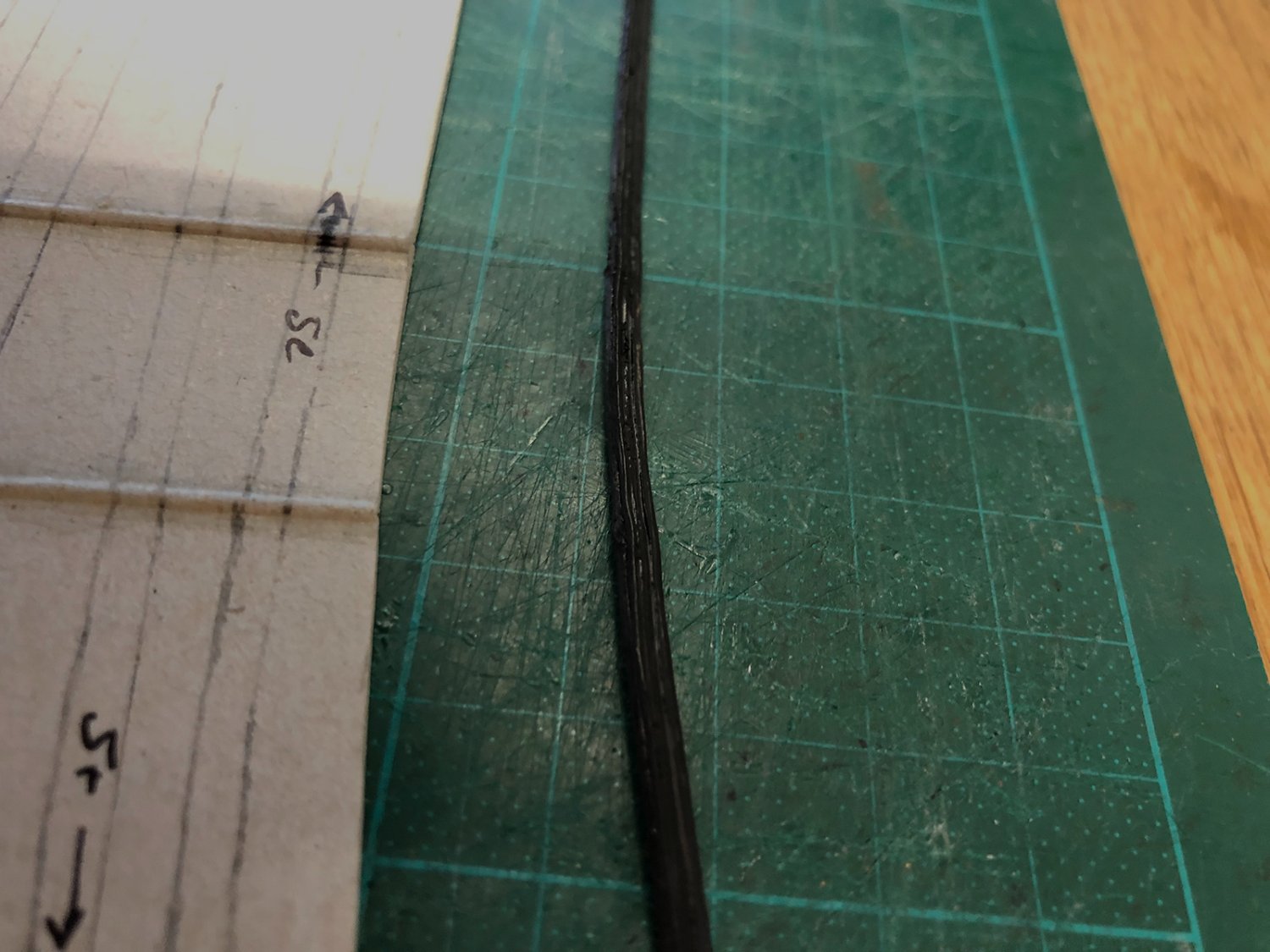
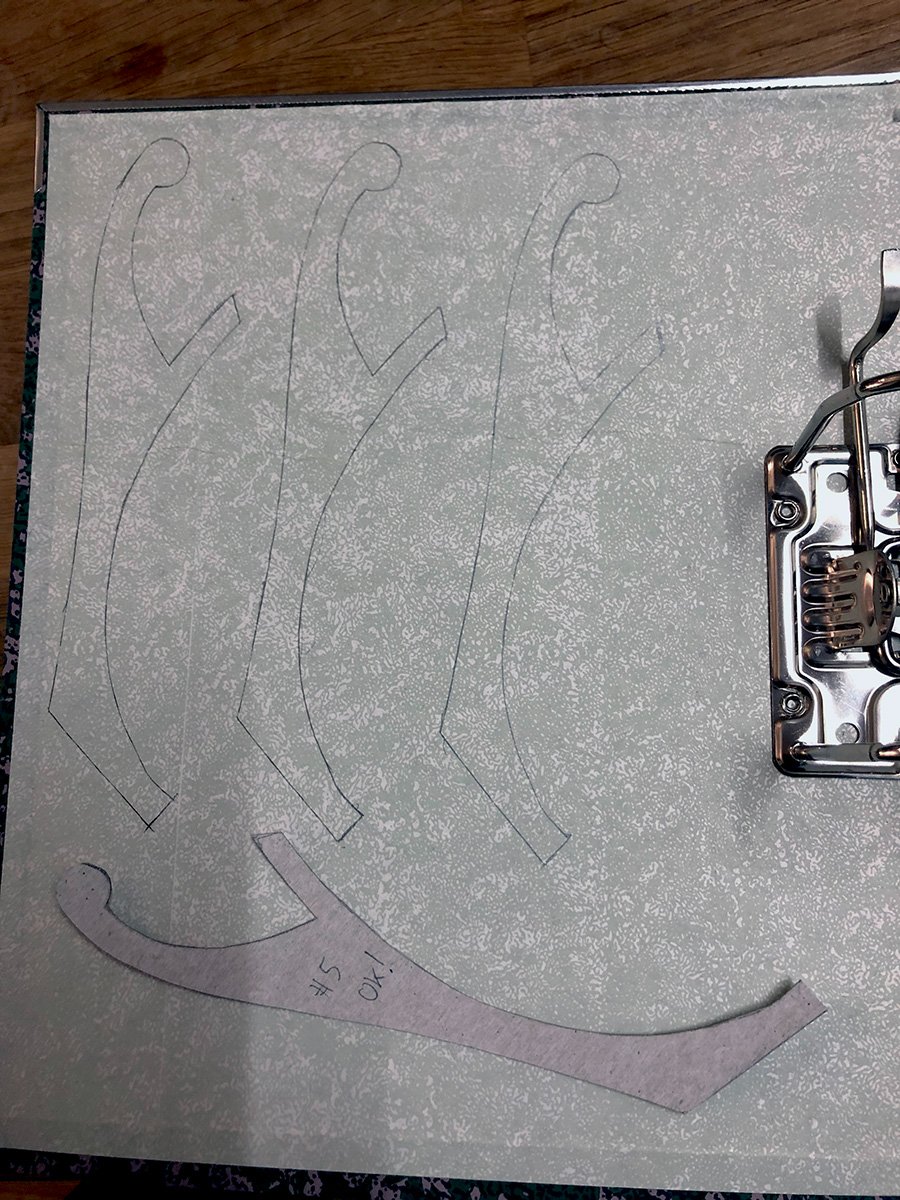
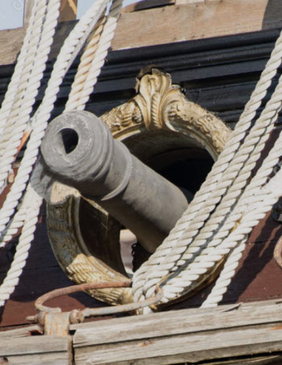
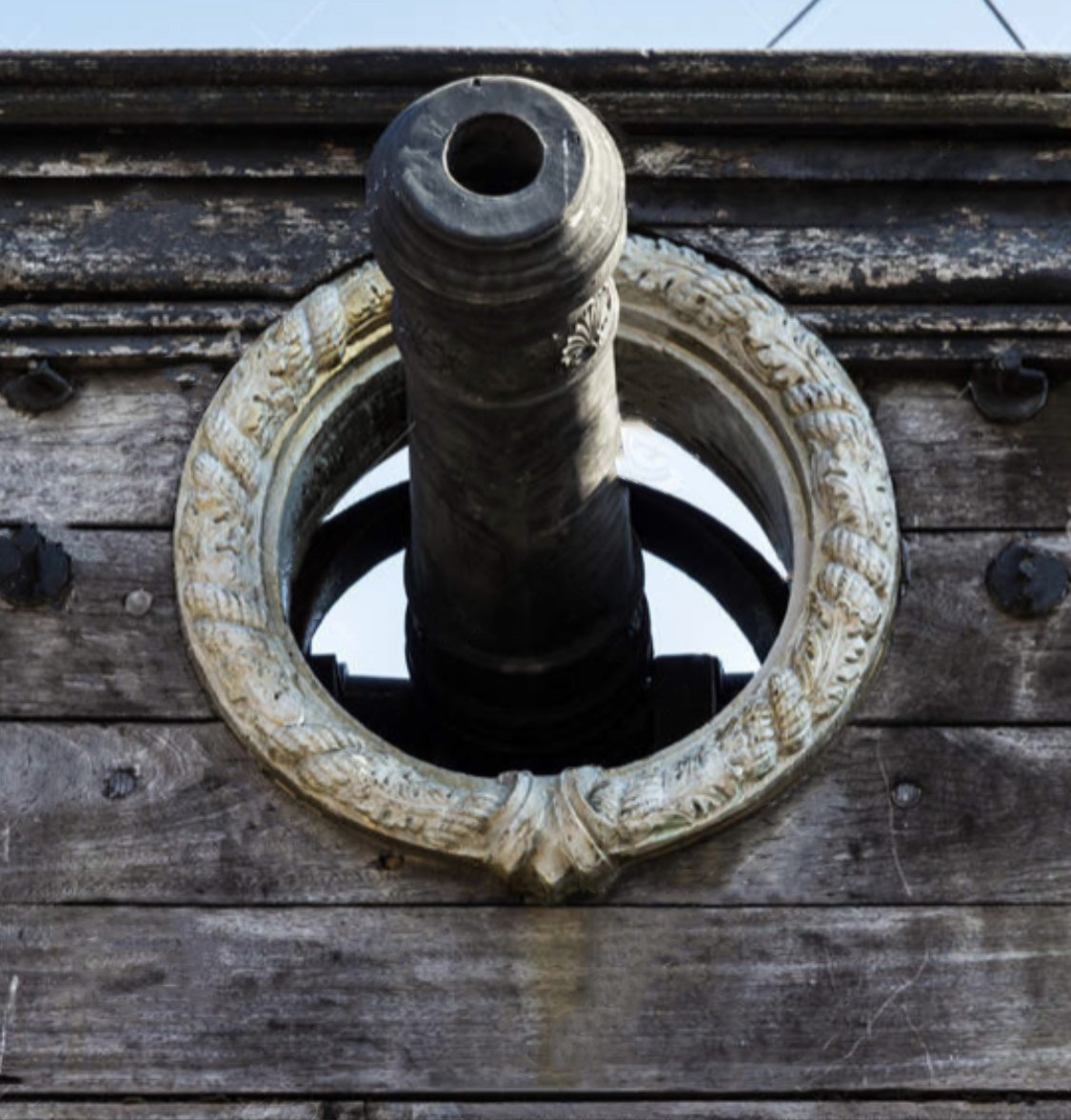
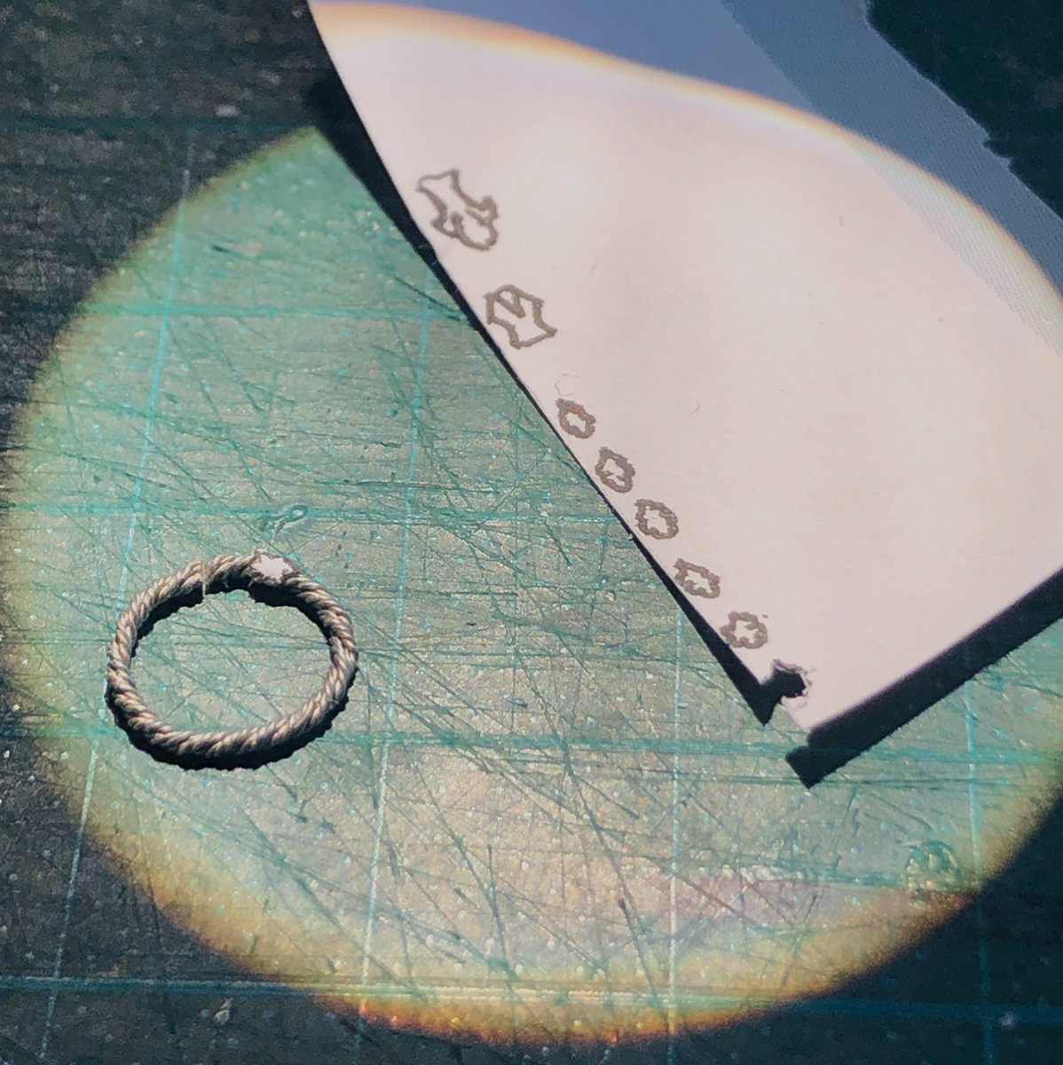
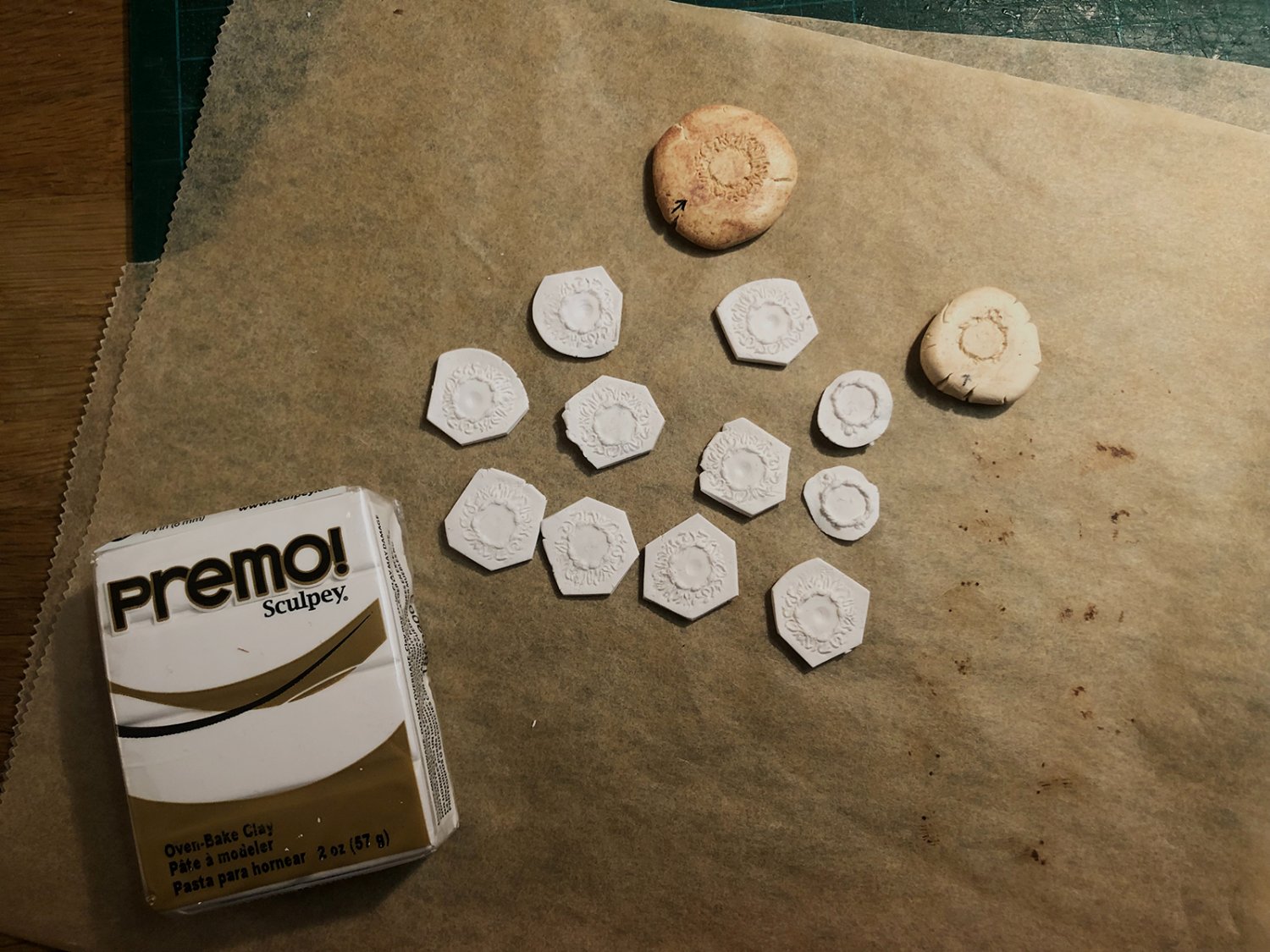
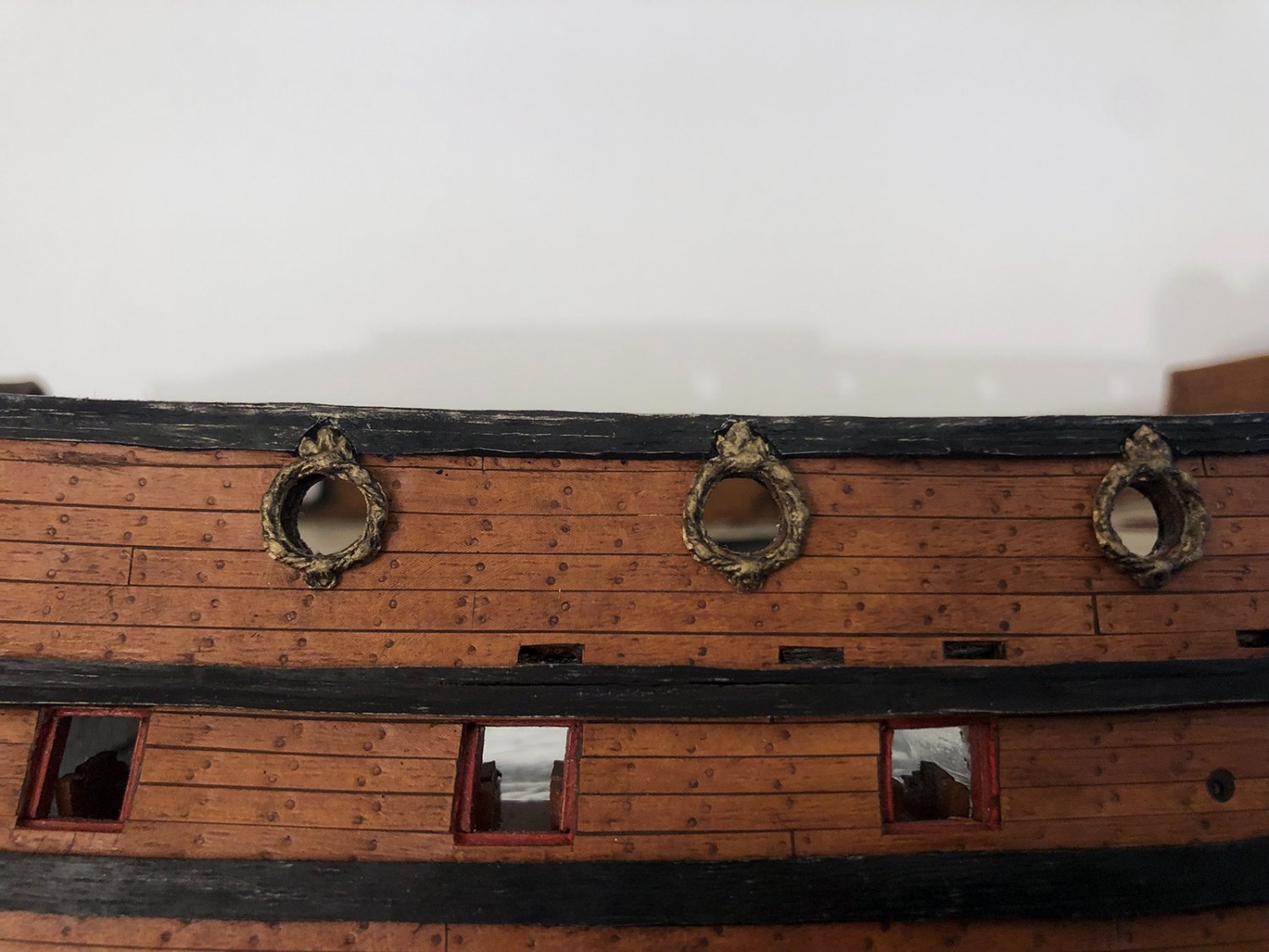
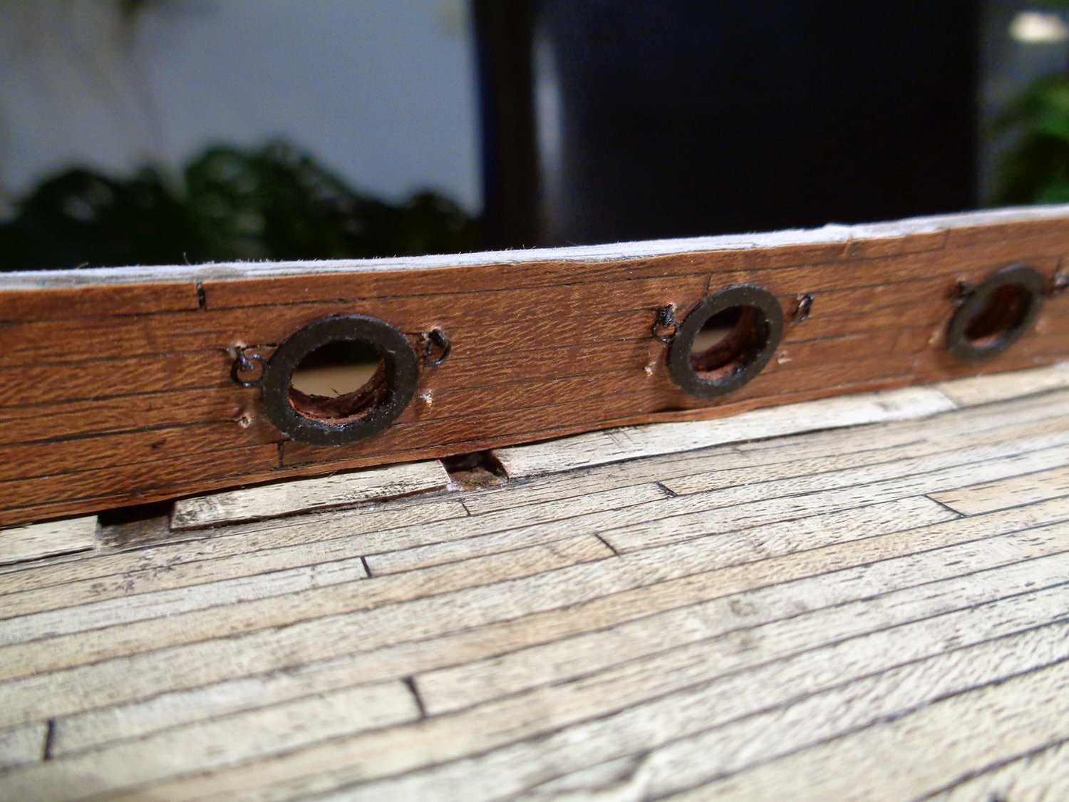
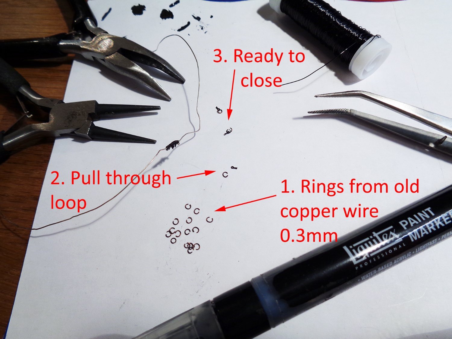
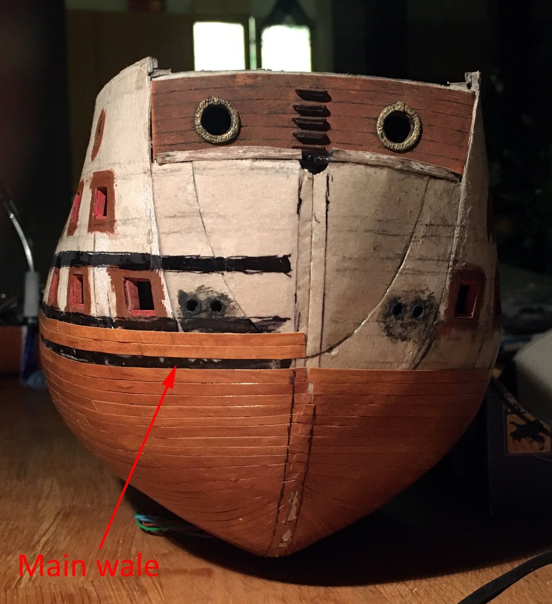
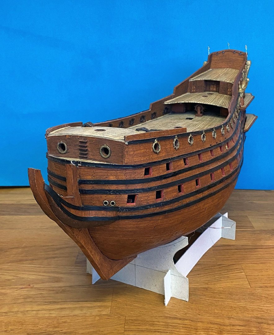
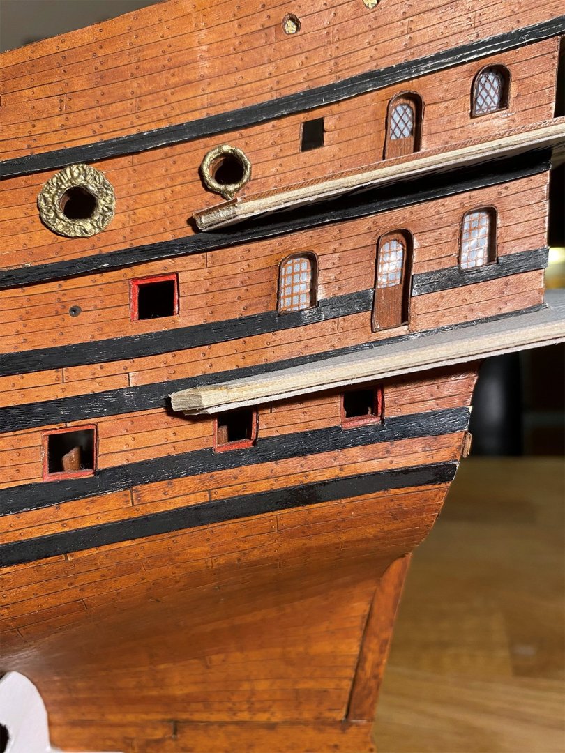
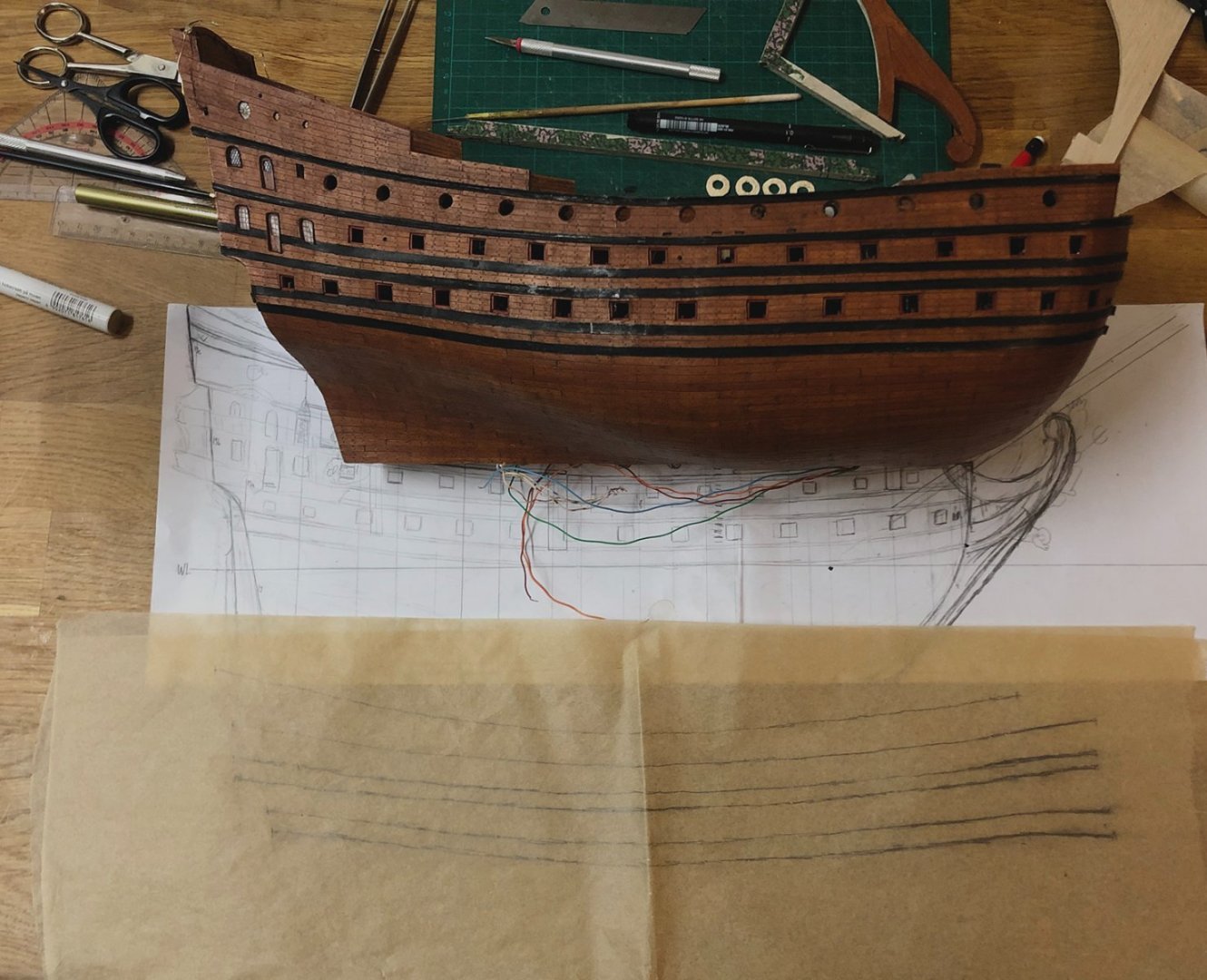
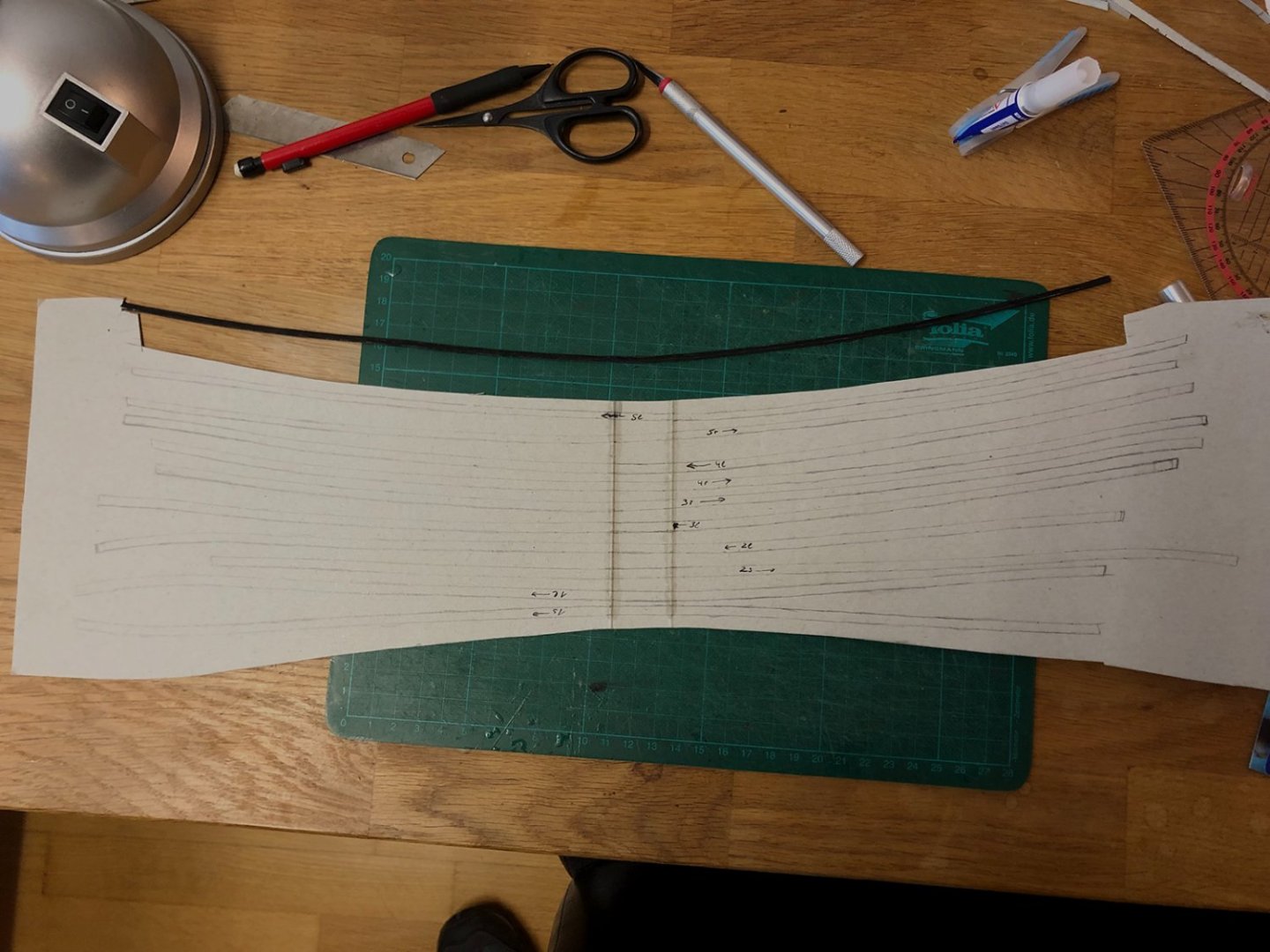
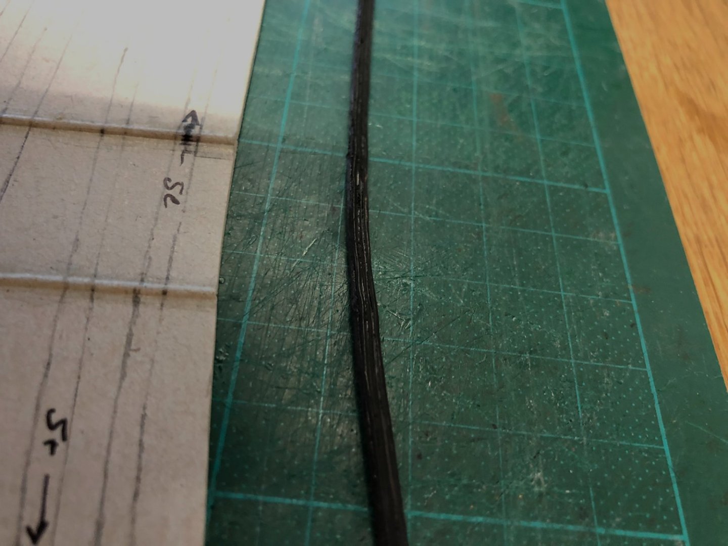
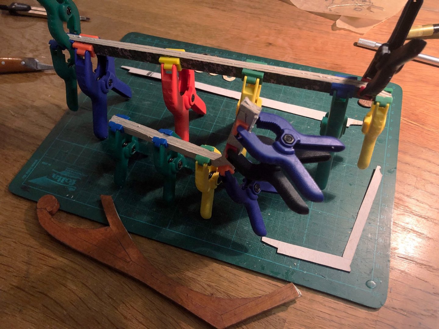
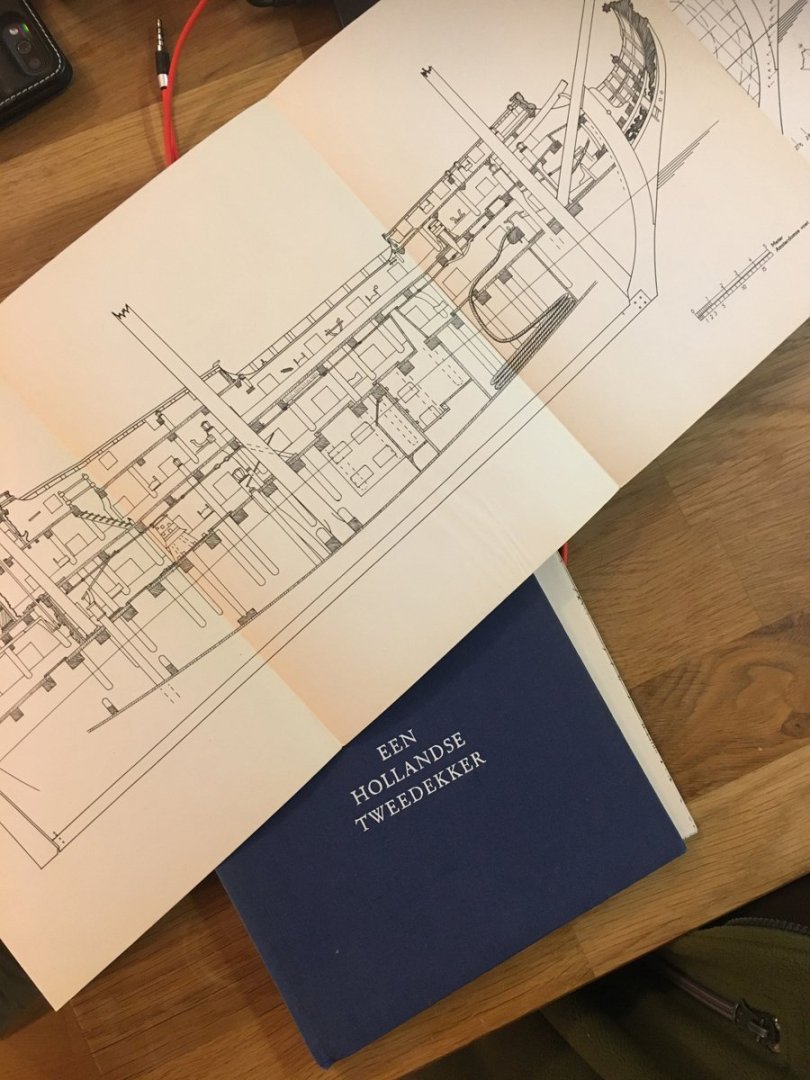
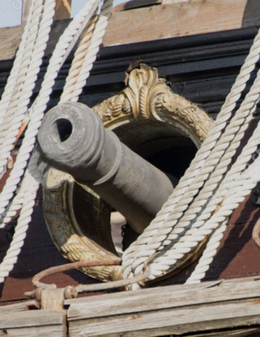
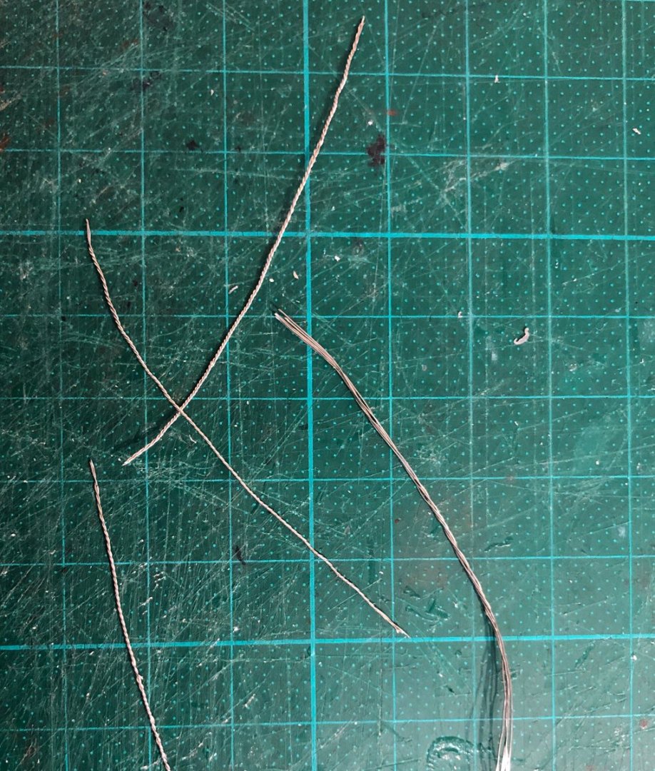
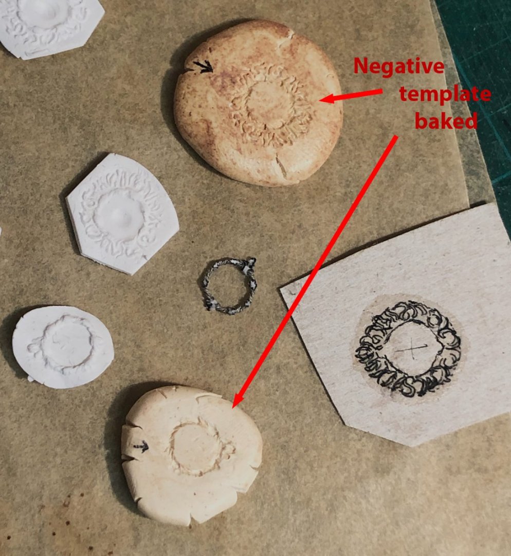
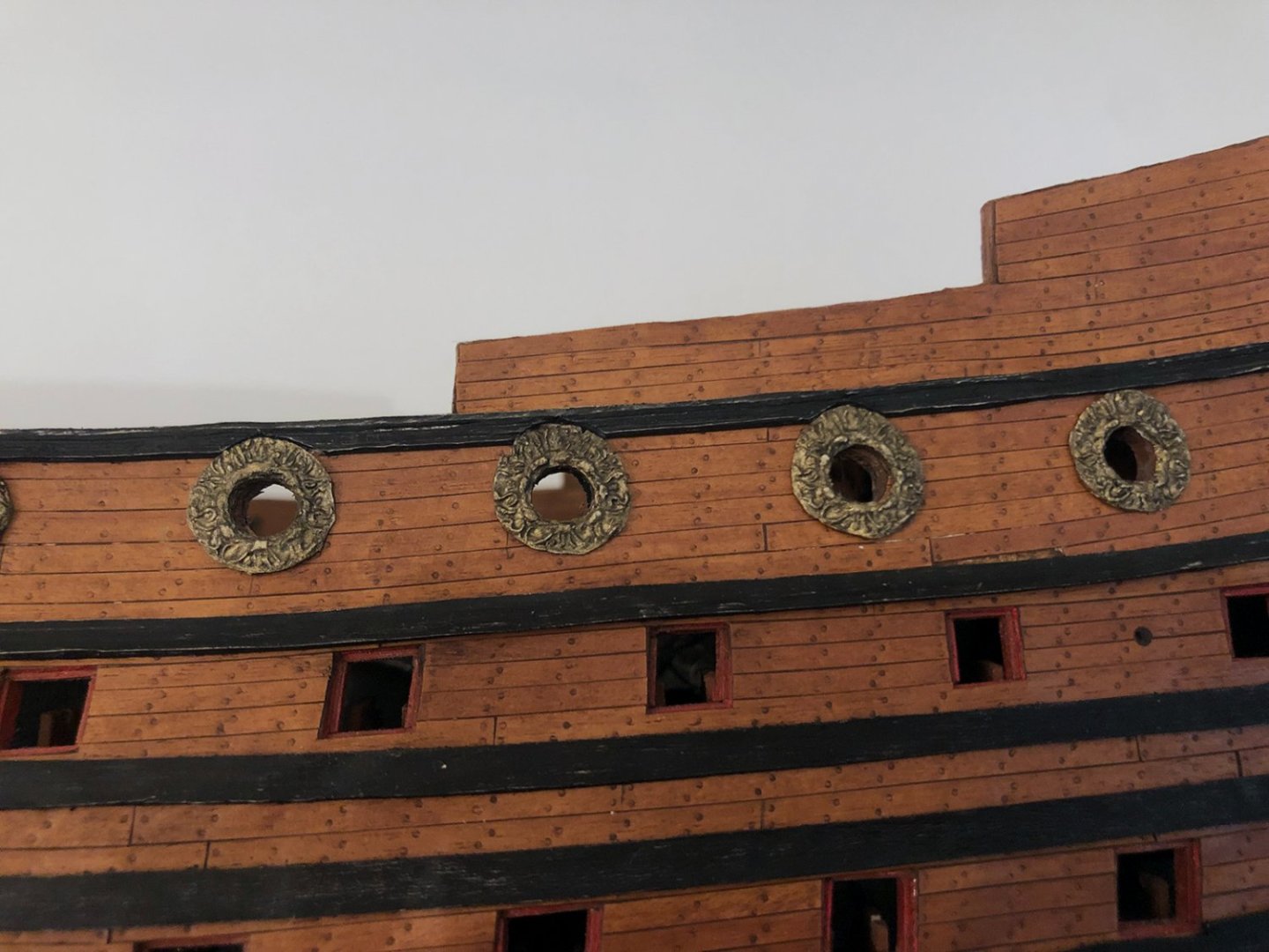
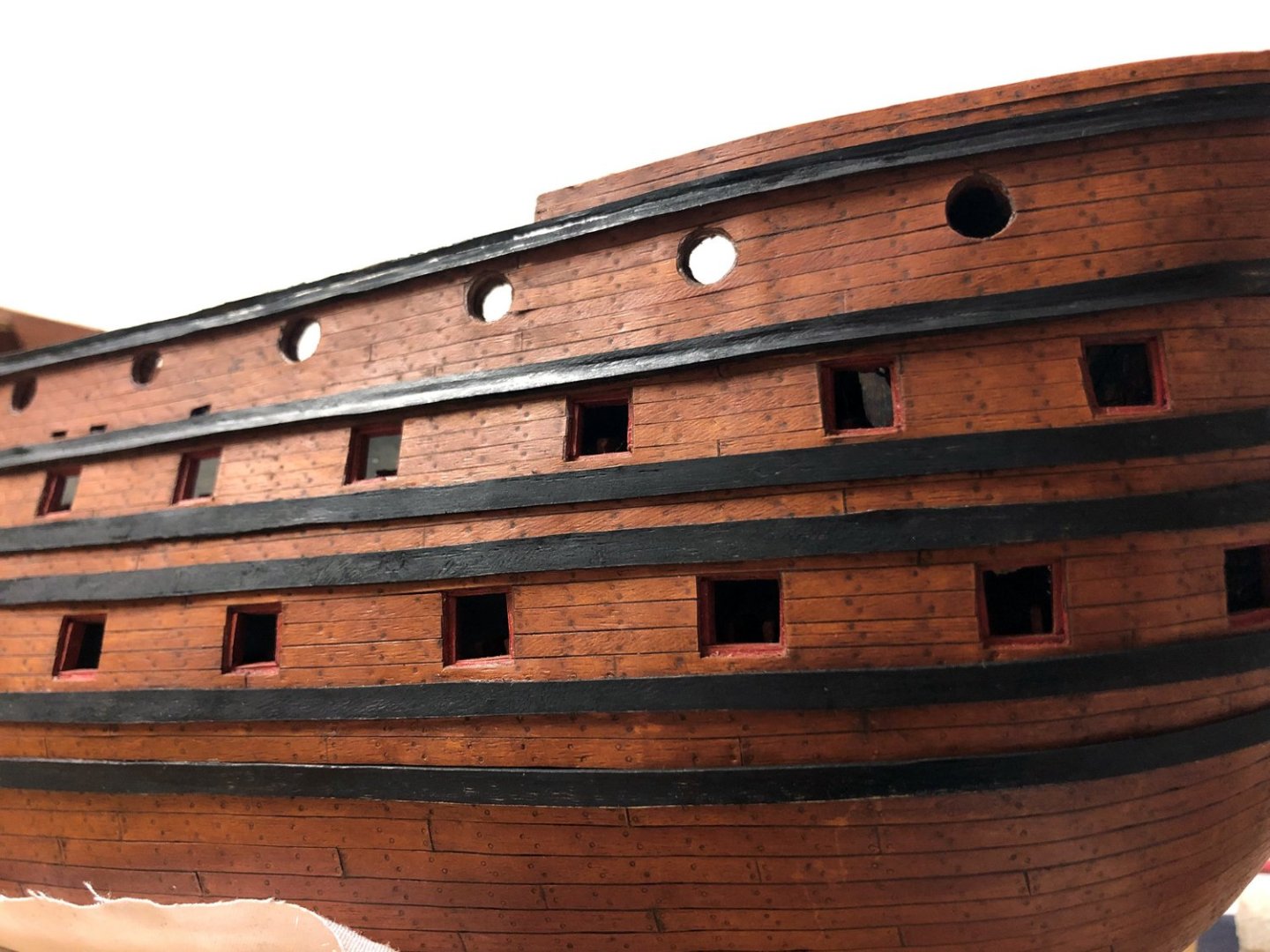
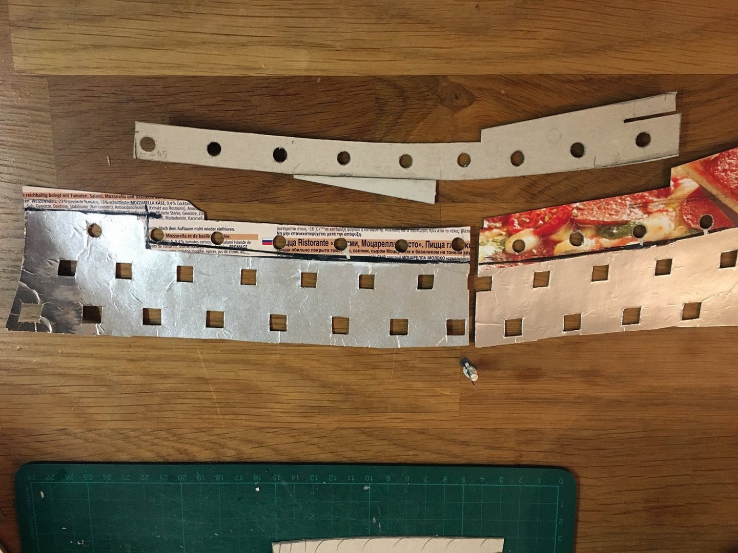
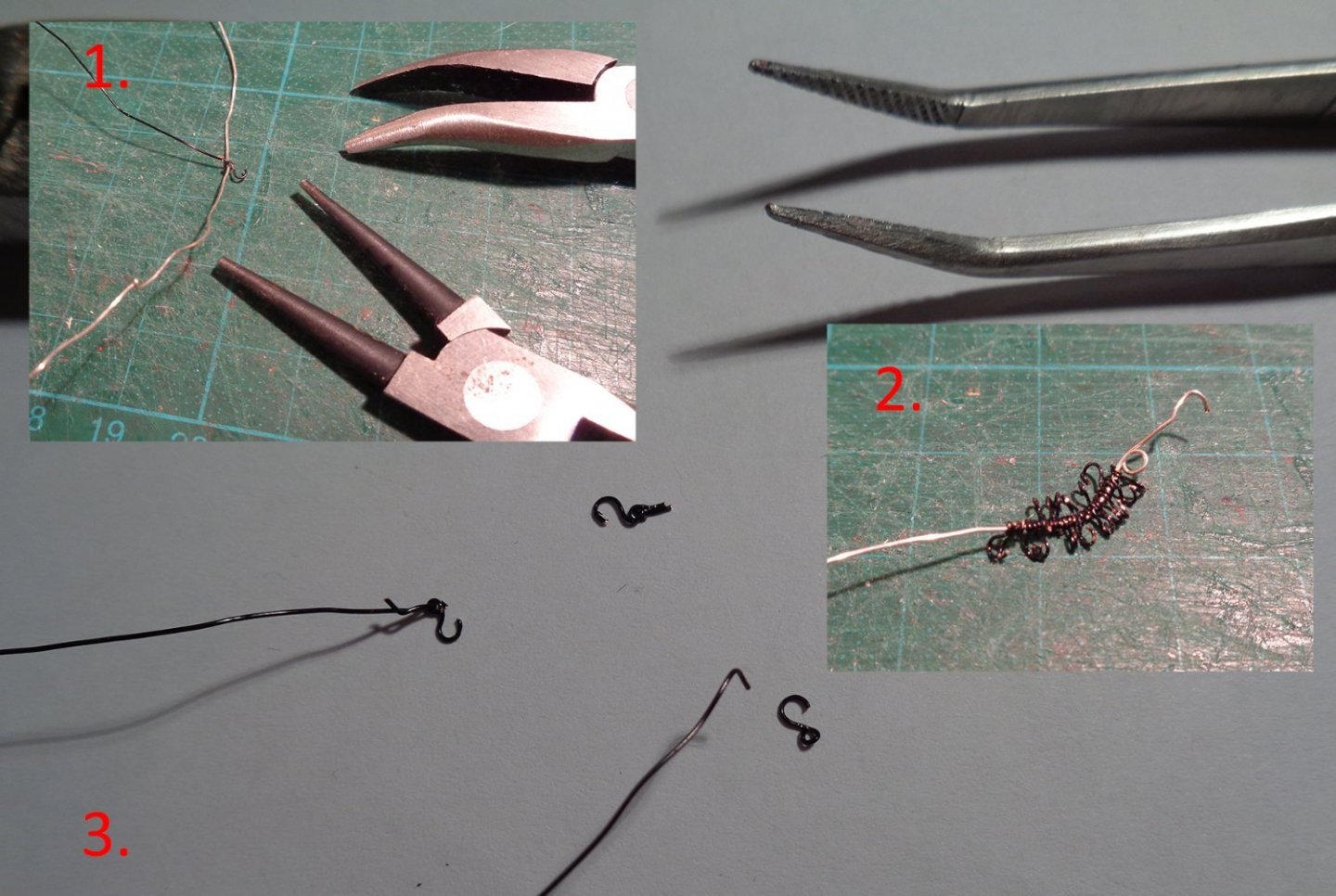
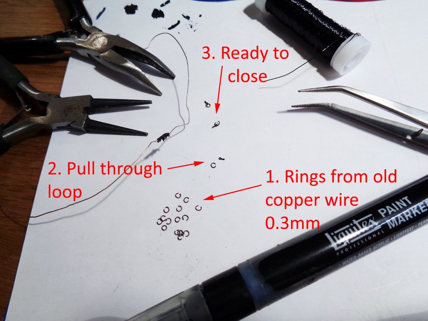
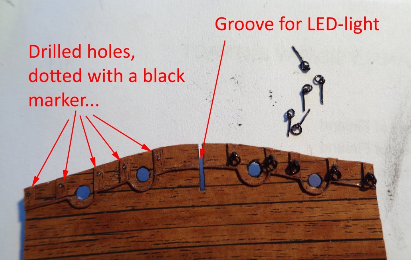
Hi there! Thank you Ab! And thank you all who follow this build and like it. Here a short description on the wales: First I traced the wales with a pencil on semi-transparent baking paper to get the curvature of each wale right. Then, after a few template tries I copied the right ones onto pizza cardboard, cut out, taped with the self-adhesive foil and painted black (first with a water-proof marker, but since that was too shiny I painted again with black oil paint) The two uppermost wales have a relief. I tried to imitate it by glueing a bit thinner and maybe half a millimeter wide stripes onto the 3mm wide wale after which I also taped it and painted. However, the foil did not go so well into the grooves as I imagined so maybe in future when making such relief wales, I will not use the foil anymore. The wale at the back of the ship has a lot of nails, which I imitated by using a bit more of the burned umber brown oil paint. In the next picture you also see a lot of pieces that are coming off at the edges. This will be all fixed and glued back in place, no worries... Then I tried to make the keel. For this I got inspired by the "Nuestra Senora de la Concepcion y de las Animas" as well as by the plans for the famous 17th century dutch two-decker model, of which I have a book from Ab. This will be also my next project, and the Neptune build is like kind of a tryout of different techniques so I do not screw it up when starting the two-decker... So after again making a few templates first (five until I got it right) to match the curvature of the bow, I made the keel from three times a 2mm thick card glued together with white glue, then taped with the self adhesive foil and altered with brown burned umber oil paint. For the long part of the keel I am currently waiting for some plugs for the cables so I will continue with that part soon. Meanwhile I was wondering how to make the ornaments around the gun ports on the upper deck. They have an inner diameter of about 6mm, so for me this is too small to model by hand from the clay. I tried with the two ones at the front of the ship, but I struggle to repeat that delicate work for the other 16 ones (or 24 including the eight larger ornaments). So I made a "rope" from tiny wires, remembering that some model makers did indeed use wire for imitating ropes for the rigging. The template is a "3 x 3 wires" shaped into a ring and some "leafs" made from paper glued on it, then hardened with super glue (CA). I used this ring as a template to create a "negative" form from the clay, which I used to do the ornaments. The clay is supposed to be baked at 150 degrees centigrade for half an hour. It can get a bit brown in the process and like DORIS described, you can actually bake it over and over again. I set my oven a bit too hot and noticed that it started to "bubble" if baked too hot. After baking the clay has a hard, but bendable consistency, almost like a hard rubber ring. This makes it easy to cut and still shape a bit if necessary, while glueing. Then I painted the ornaments with a "gold" marker pen and altered with turpentine diluted black oil paint. However, the turpentine also dissolves the golden paint again so it was a bit tricky. The following pictures show the result. For a scale of 1:100cm I am satisfied with the result, for me this is good enough. If made in a scale 1:75 or even 1:50 I would need to make a better job wih the ornaments. However, due to limited space at home I have to work in the scale 1:100cm. My apologies for the picture quality, I do not have a good camera and the light here is also not the best... So much for now. Next will be hopefully more on the keel and some more ornaments. Once the keel is in place I plan to start working on the balconies. Rgds, Radek


-
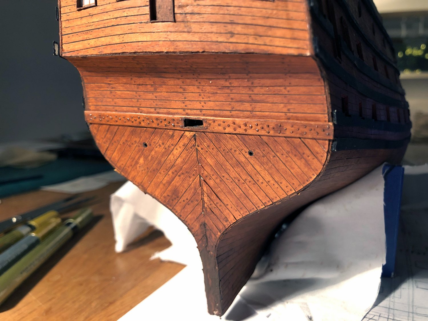
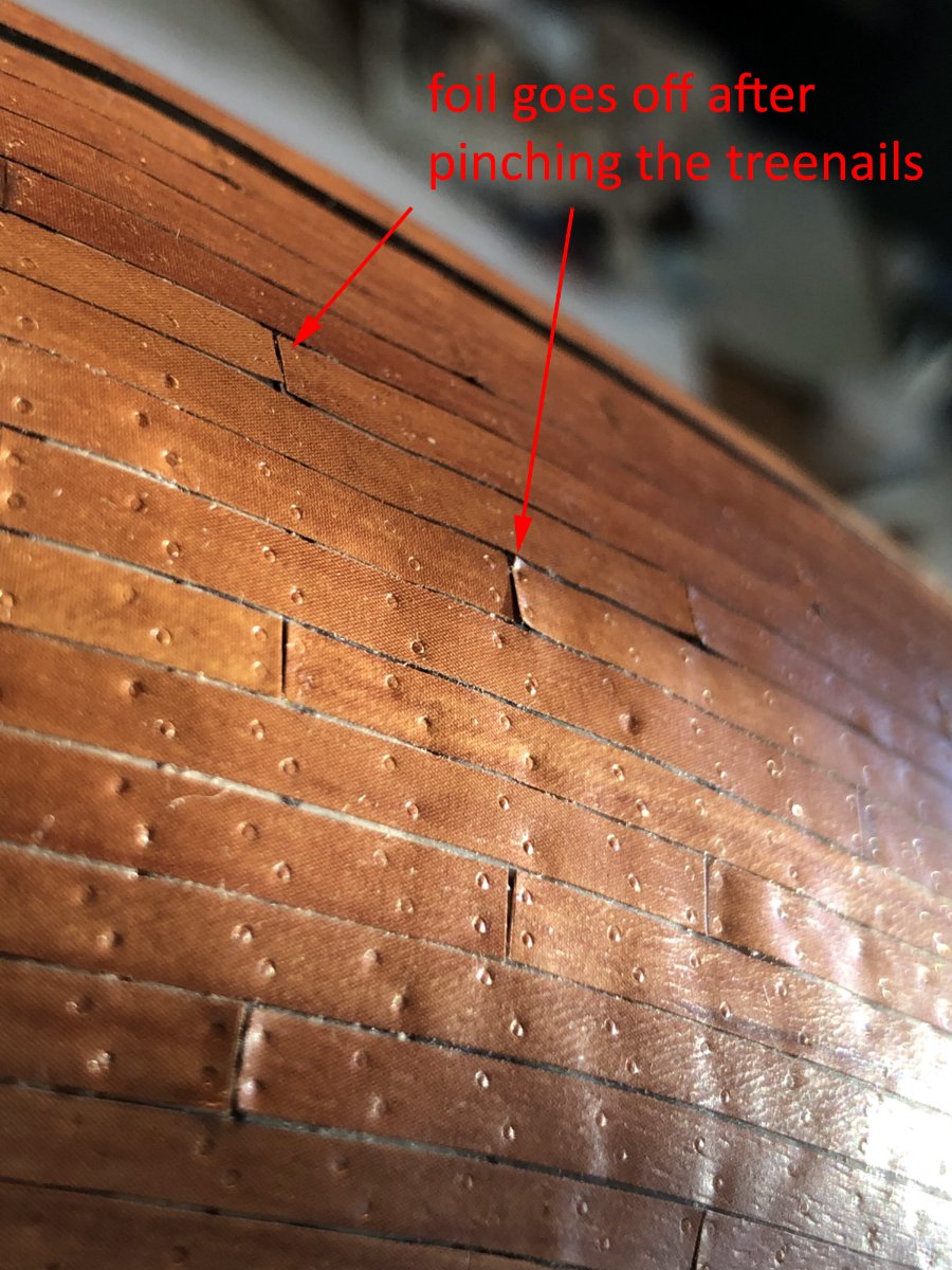
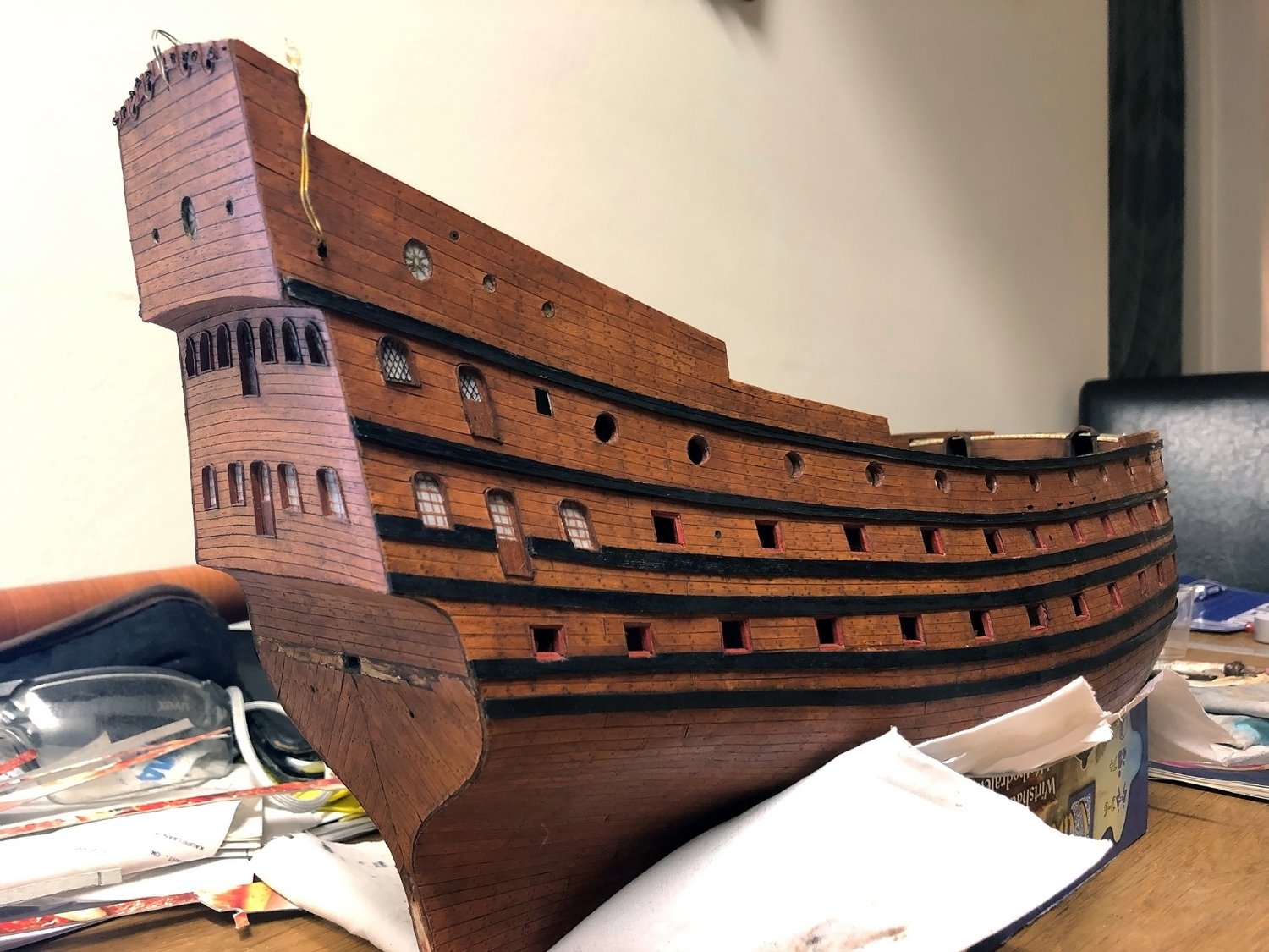
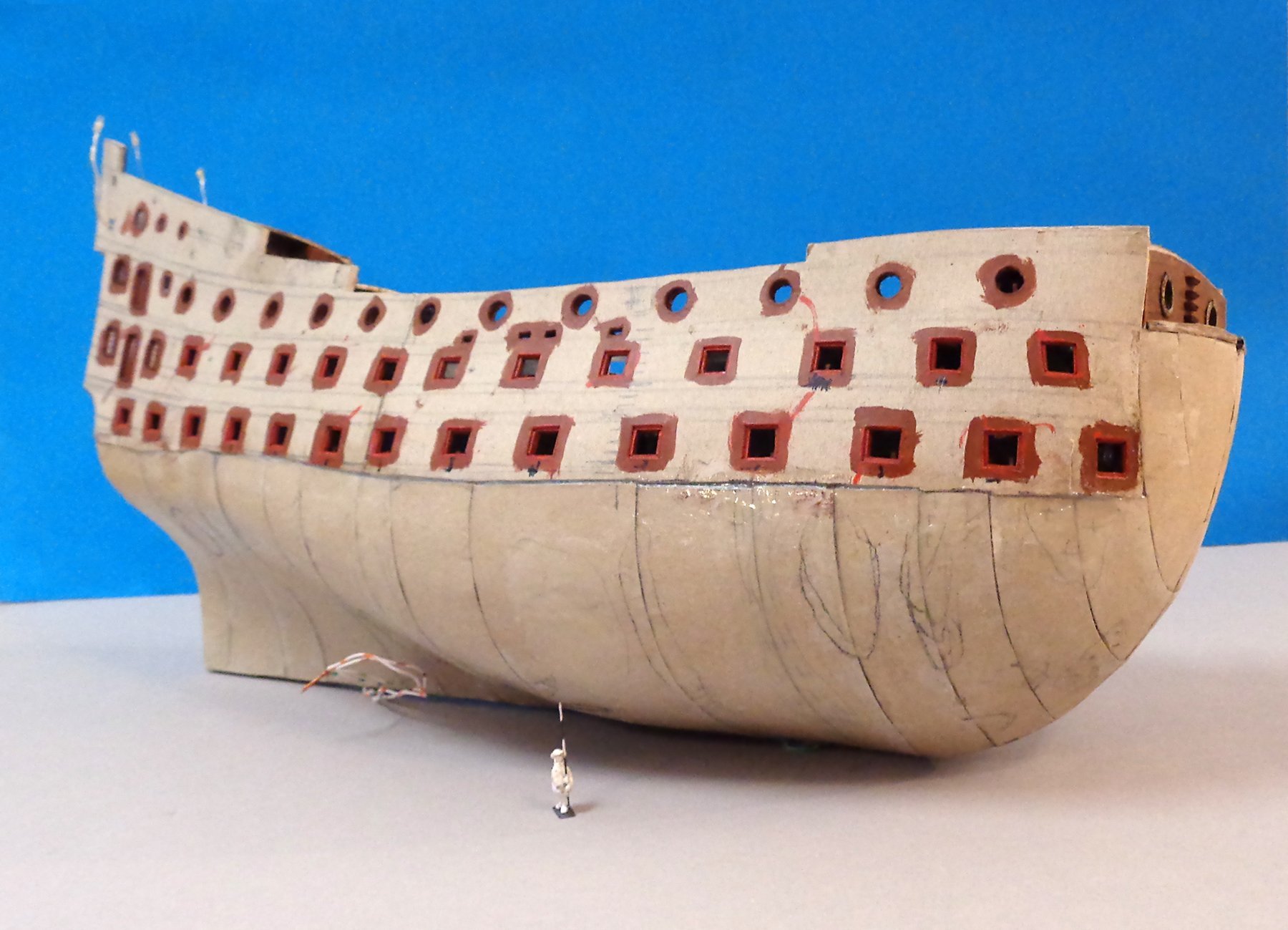
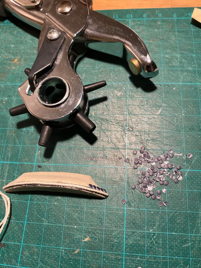
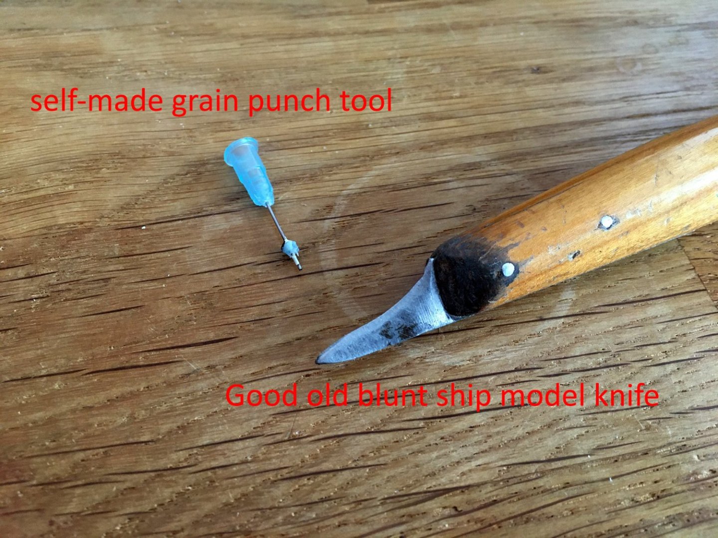
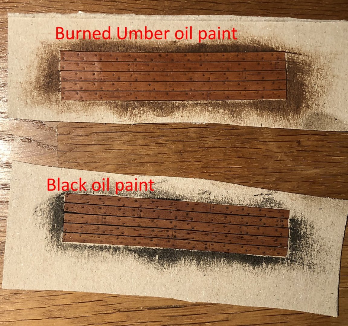
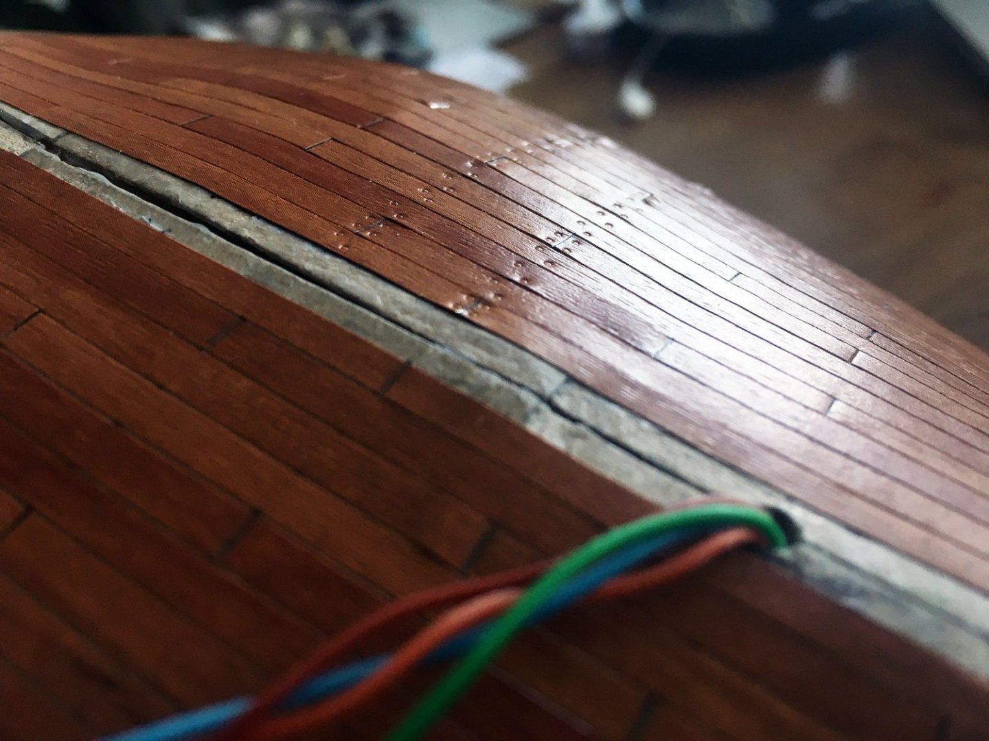
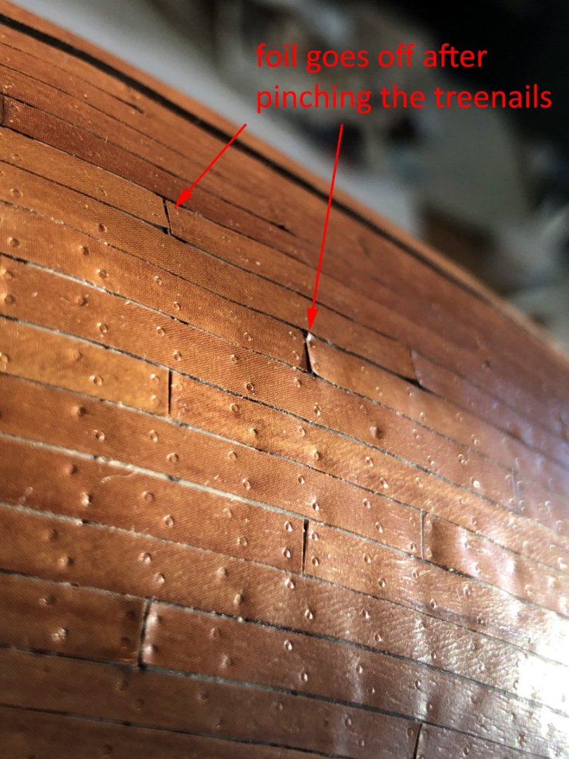
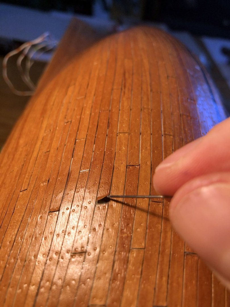
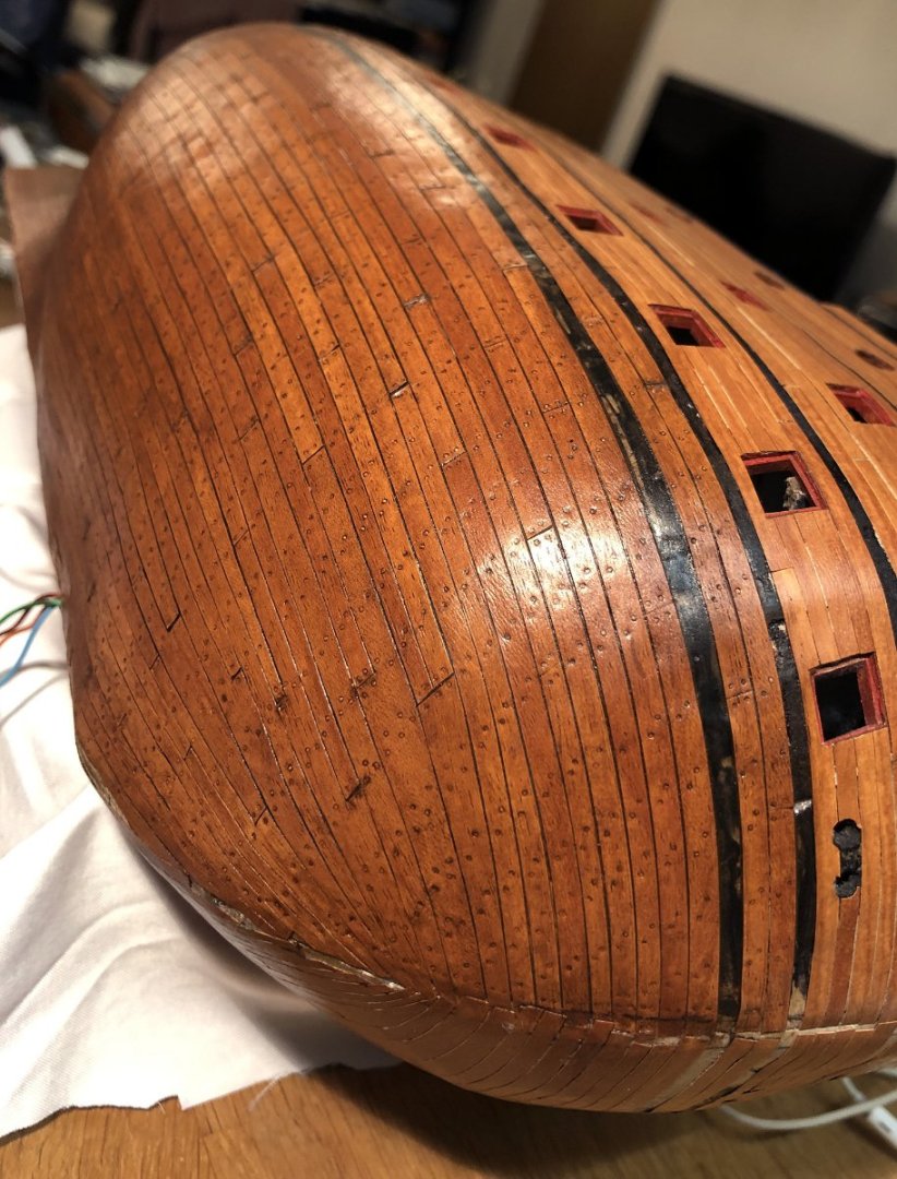
Hi there! Thanks for the likes! Here, where I live the days are again getting shorter, colder, and darker so it is time to continue this build. Afer planking the whole ship with the foil strips I decided to imitate treenails. For that I use the old technique used for wooden models, where one uses a punch tool, or a cut syringe, to simply punch the imitation of a treenail into the plank. all together I 'count-estimated' bit over about 10 000 treenails... In some of the planks that were made from longer stripes of the foil, I imitated the plank butt with the blunt ship model knife I once as a kid got from a neighbor (ship and building wood modeler). The reults look not so good prior to altering with oil paint: Where the plank butts were the actual end of the foil strip, the foil tended to go off after punching the treenails, so I had to glue them back on. Then I tested different oil paint colors for the altering. For the Mayflower I used black oil paint. But this time I decided to use brown burned umber instead. The oil paint is applied and then "smeared off" so it fills mainly the grooves. In the beginning it is all quite shiny, but gets more blunt when the oil paint dries. Currently I am glueing the wales in place. After gluing the starboard ones in place I realized they might be a little bit too wide , but, well, this is a fictive ship, so I am not correcting this anymore. Despite, if I'd try to take them off and redo, I will rip off the plank foil strips, so for this model I will leave it as is. This whole build is anyway more a "try and error" play for me trying out new (old) techniques and see what I can do and what not... Thus far, I am satisfied with the result. Imitating the treenails, which are in this model about 0.25mm, corresponding to a diameter of one inch in real size, I think the size is appropiate for such a big ship and planks of 3-3.5mm or 30-35cm width. The question was just if I "nail it" or "screw it" completely... Judge for yourself. So much for now. Next will be the keel and I will describe how I did the wales. Rgds, Radek


-
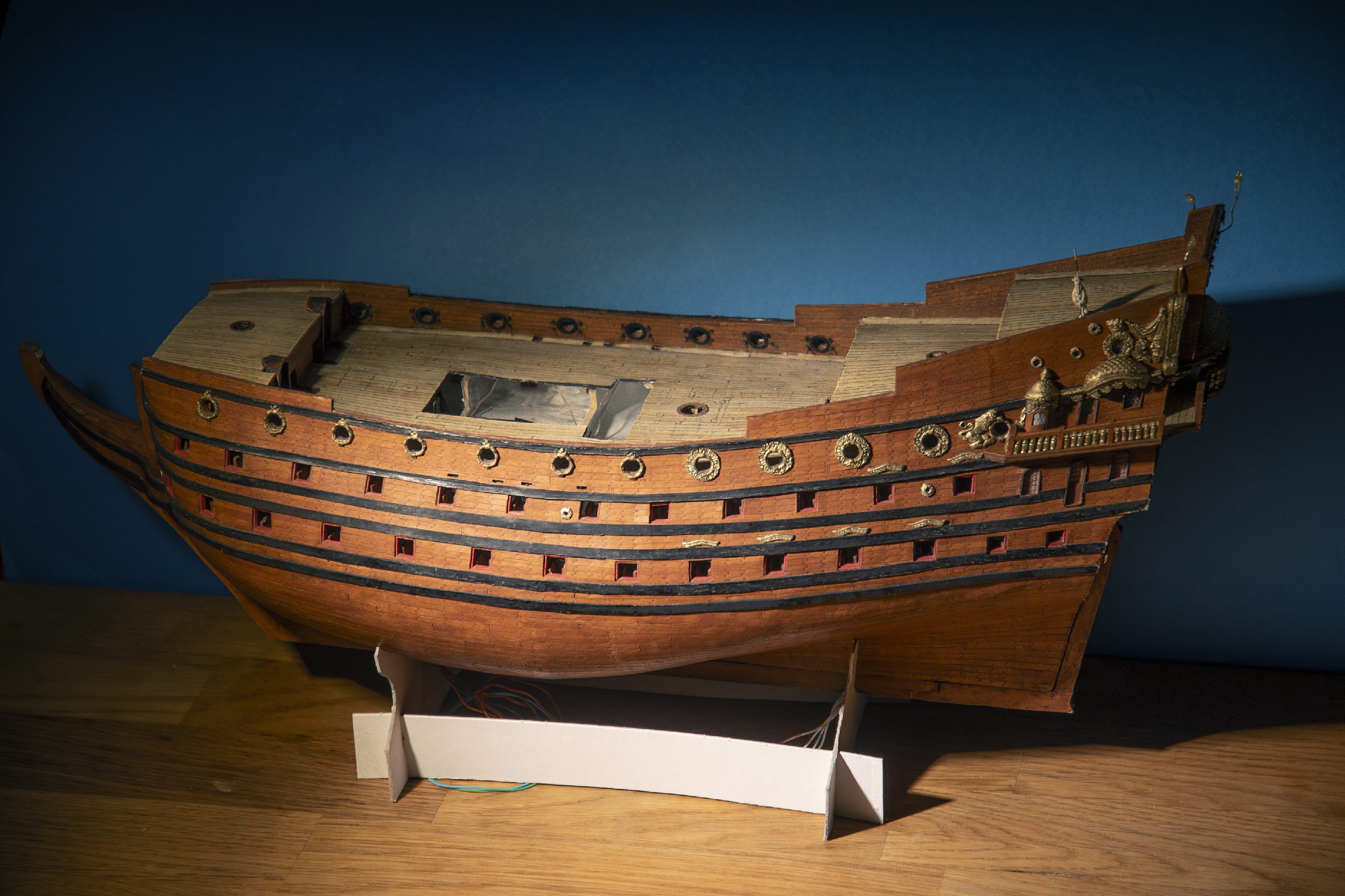
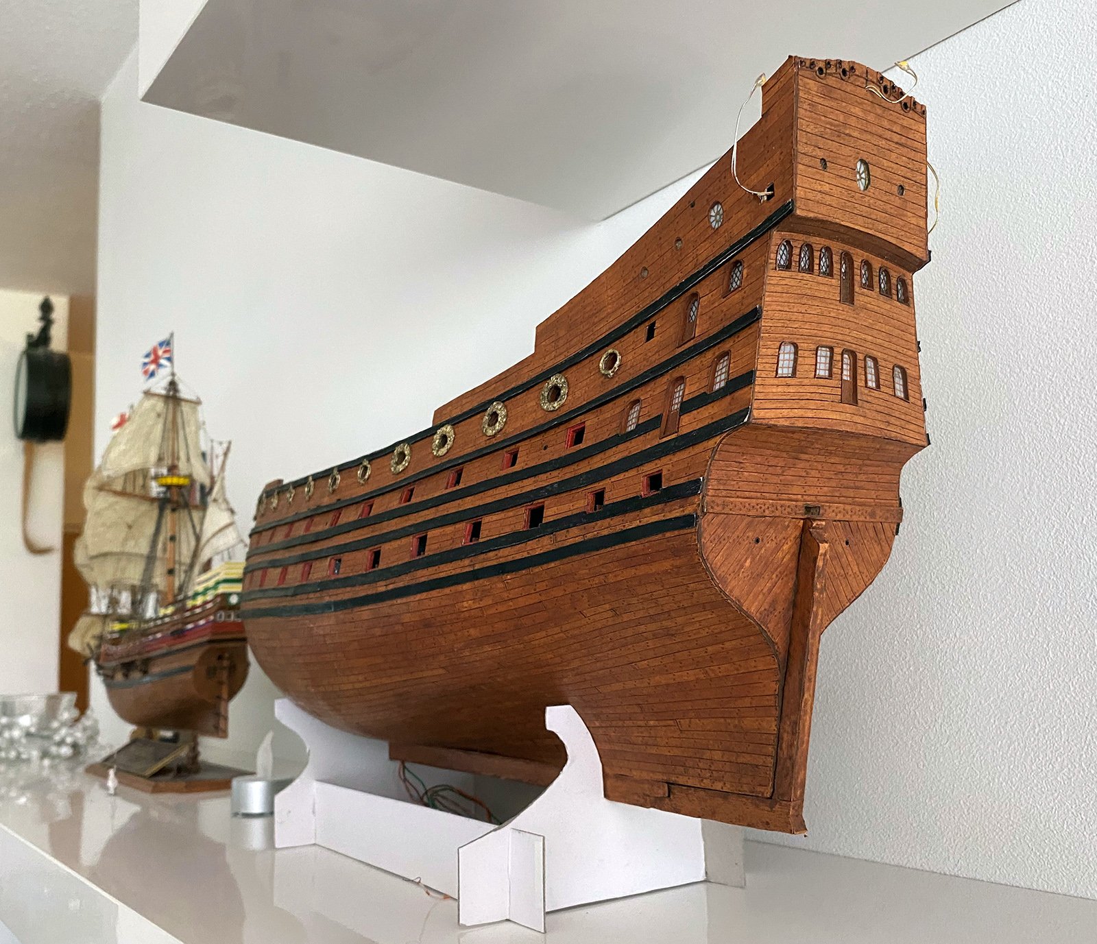
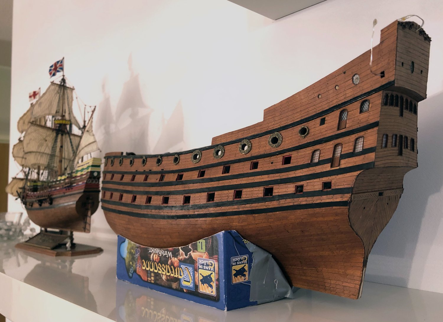
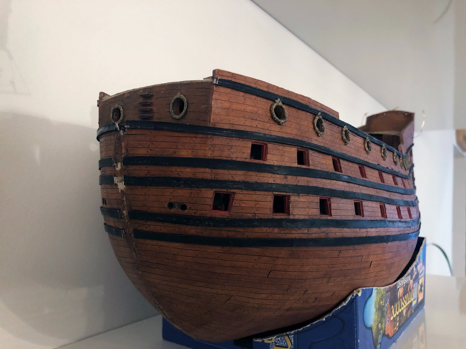
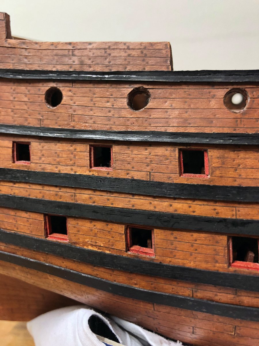
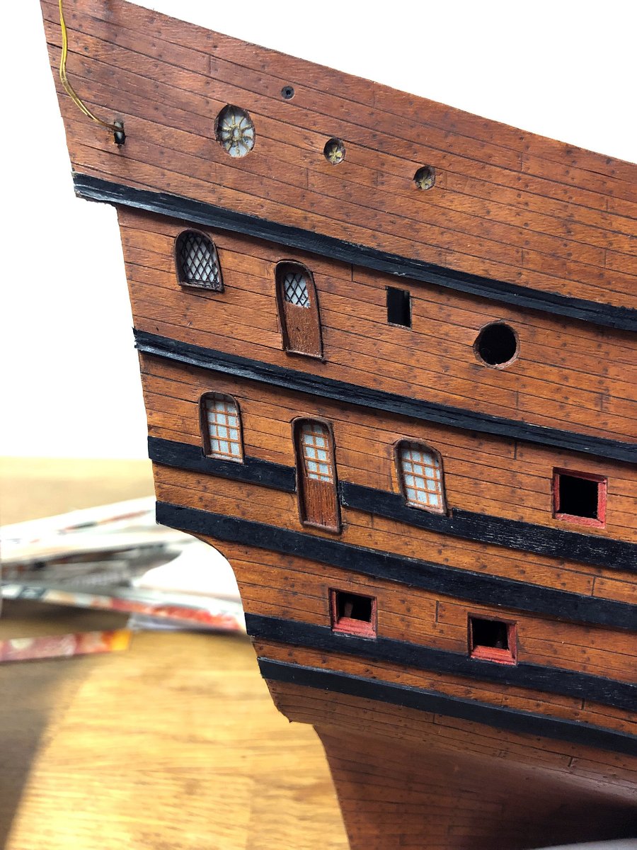
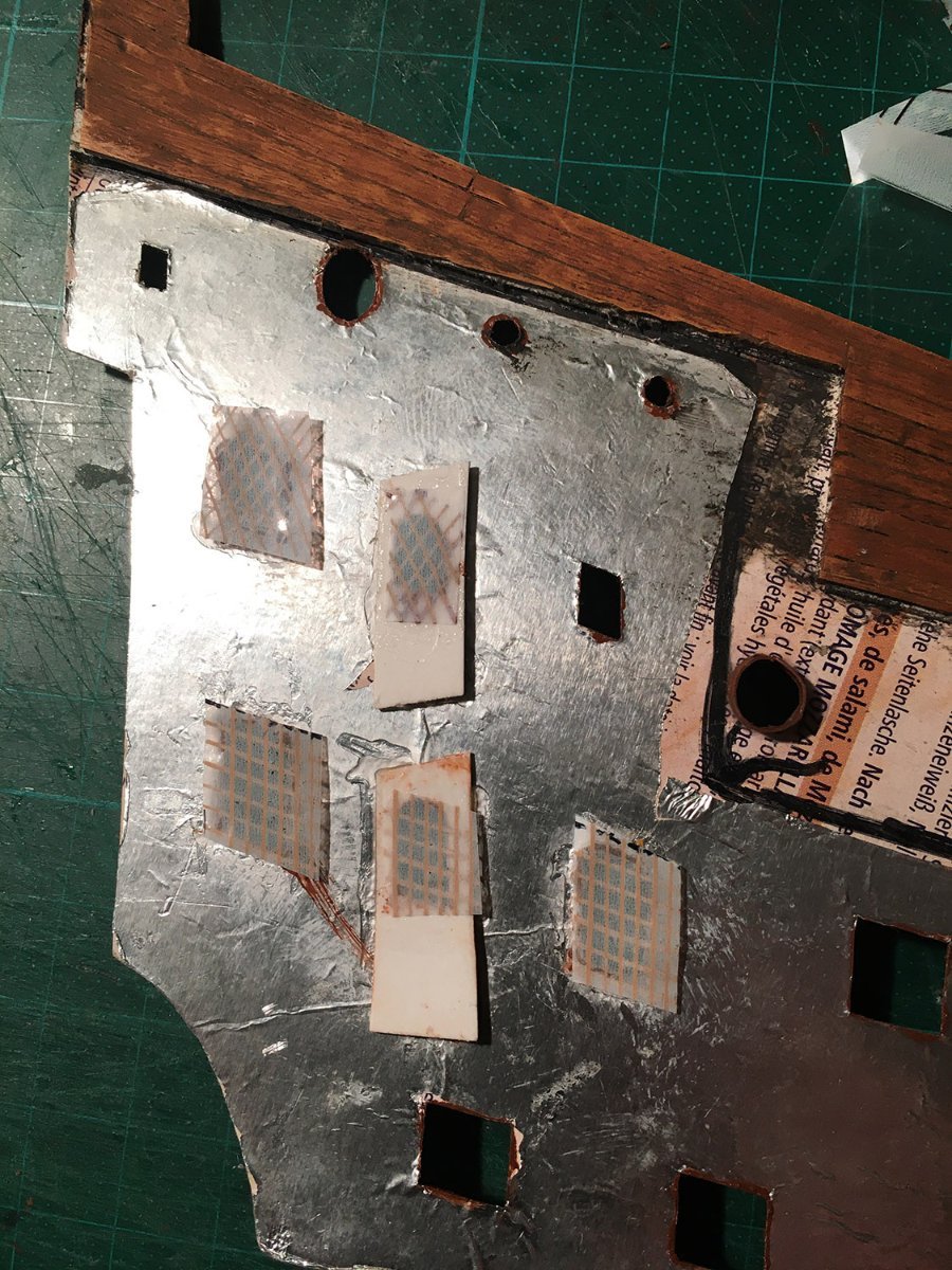
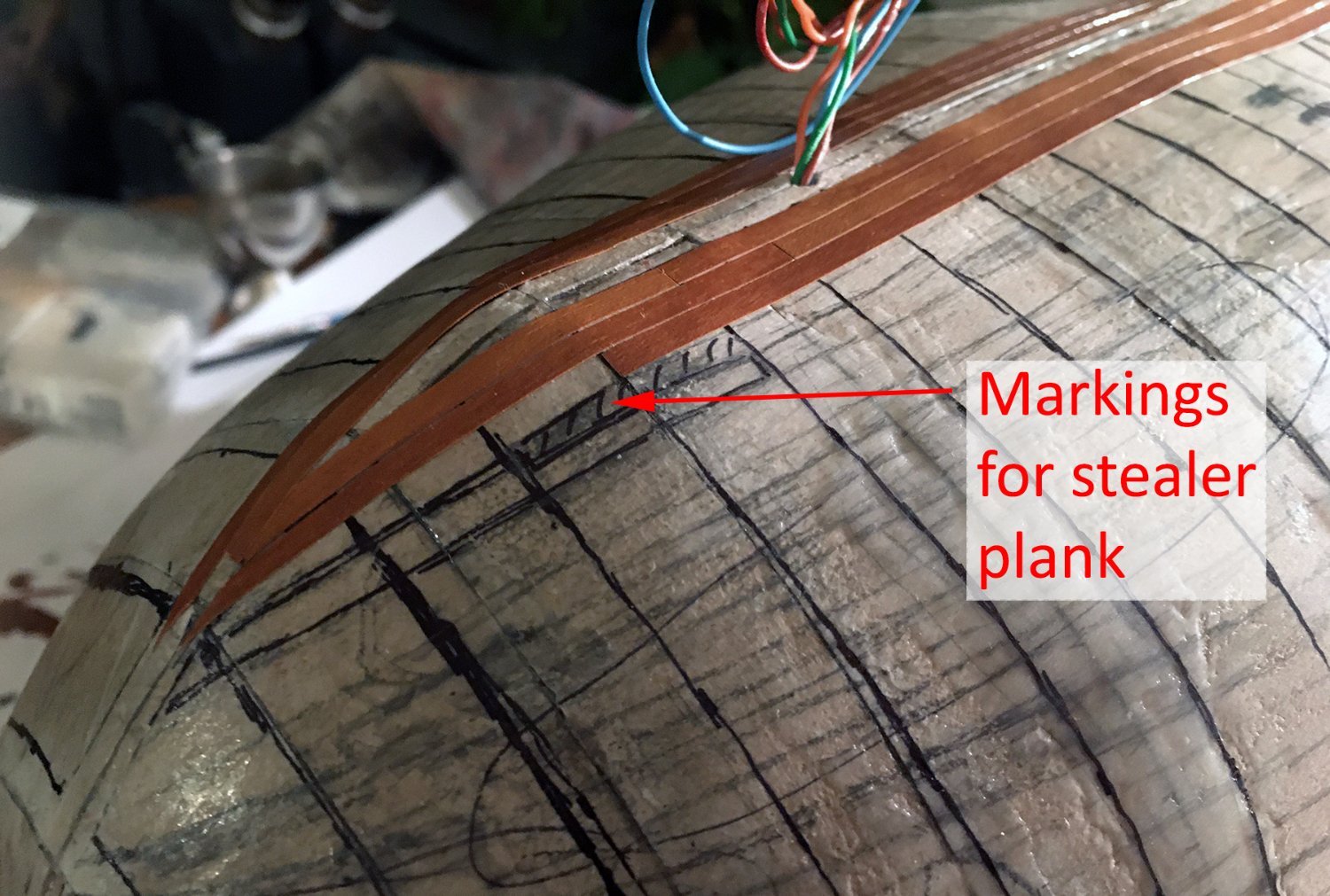
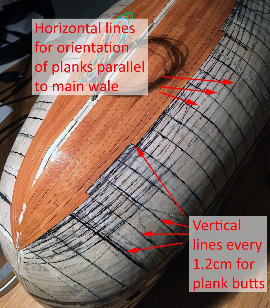
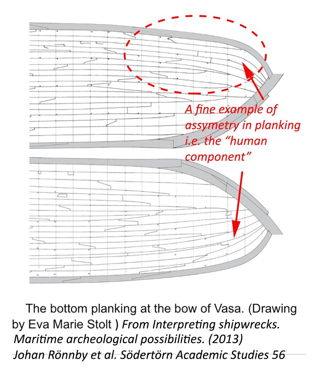
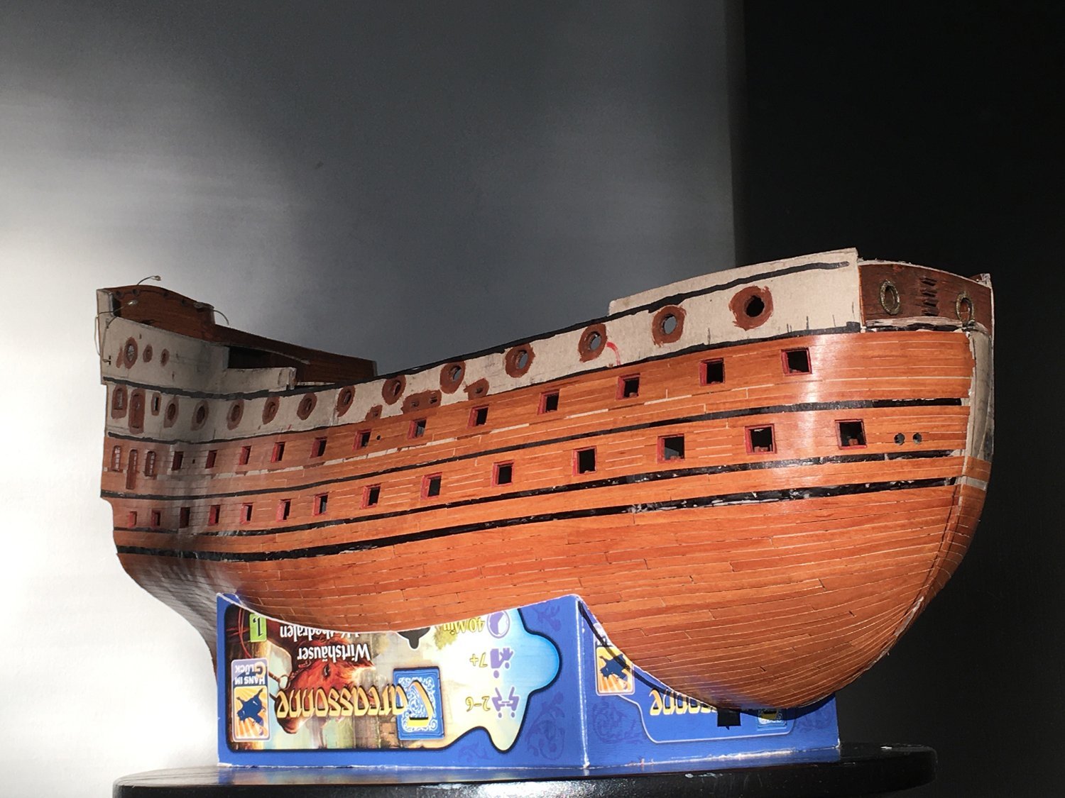
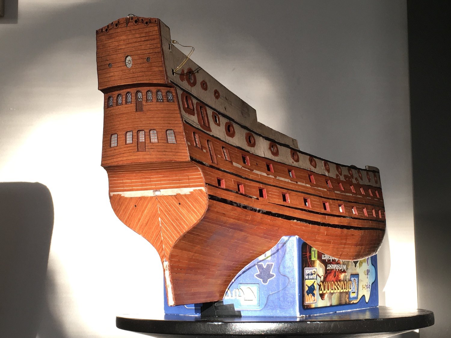
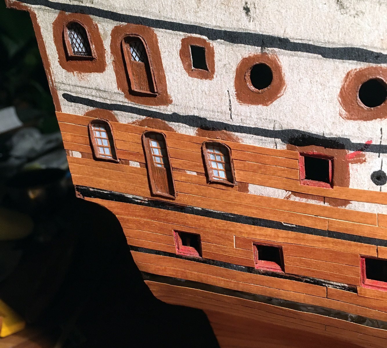
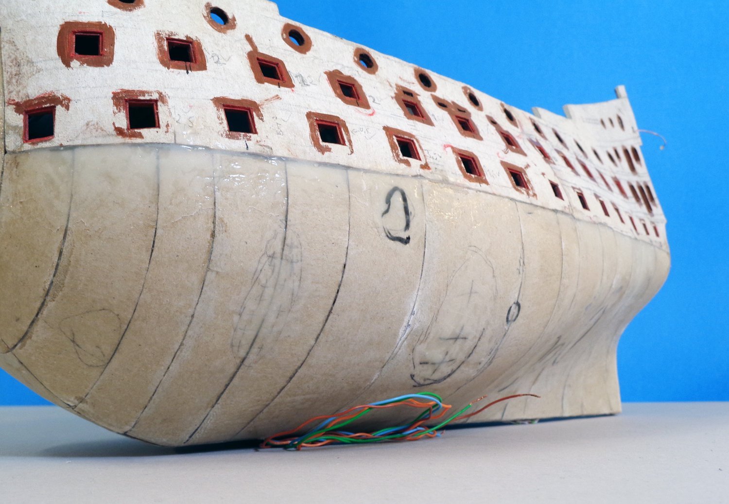
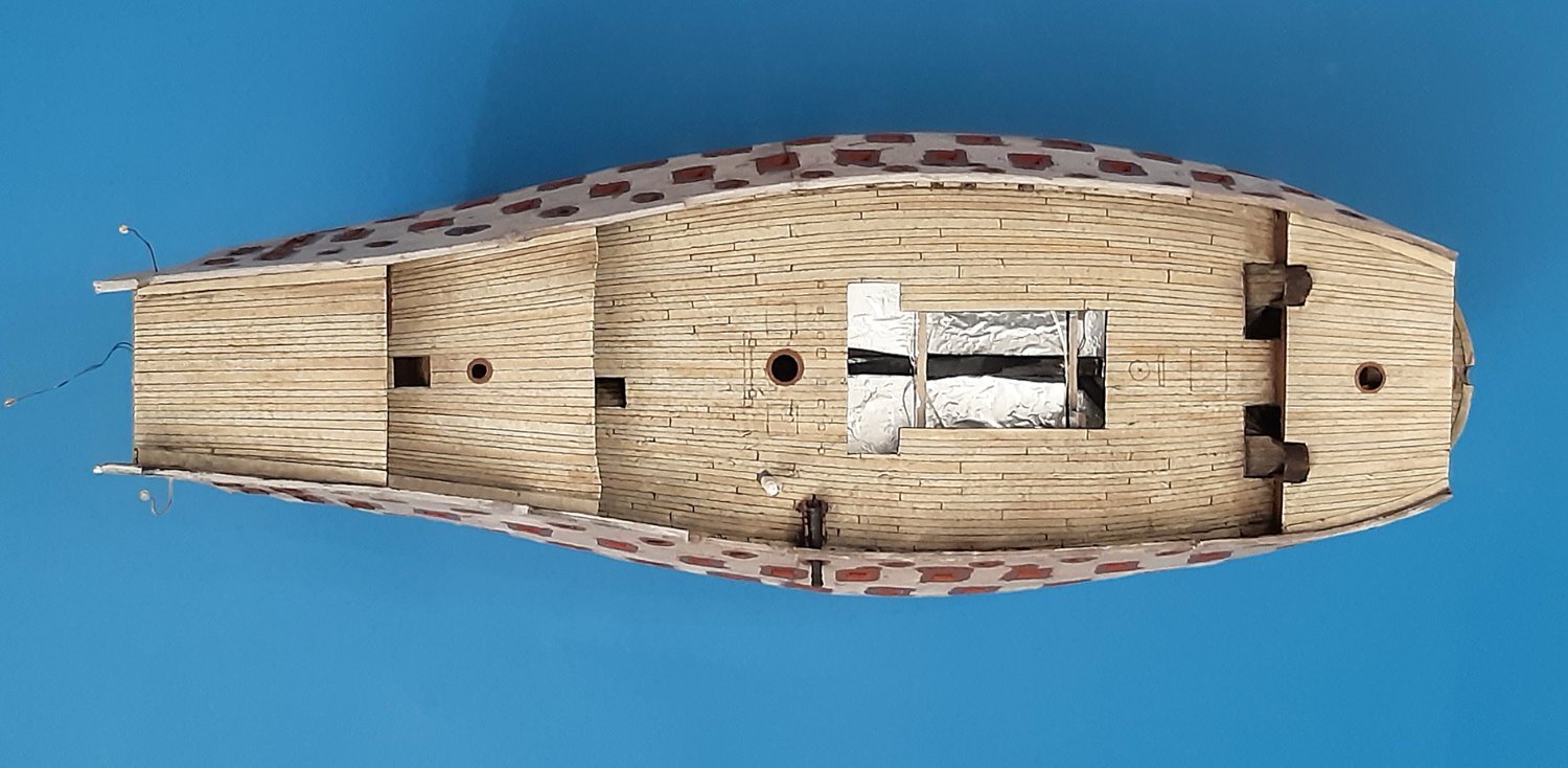
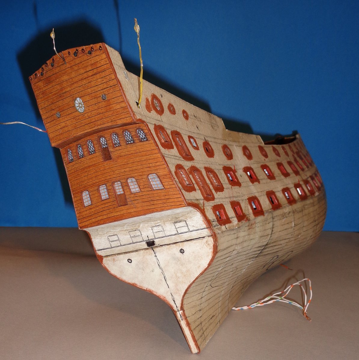
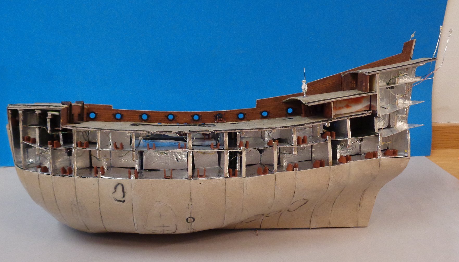
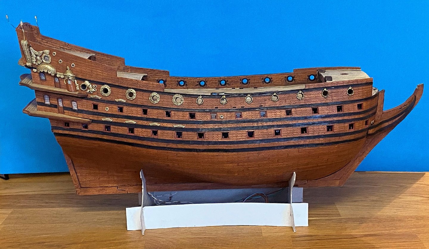
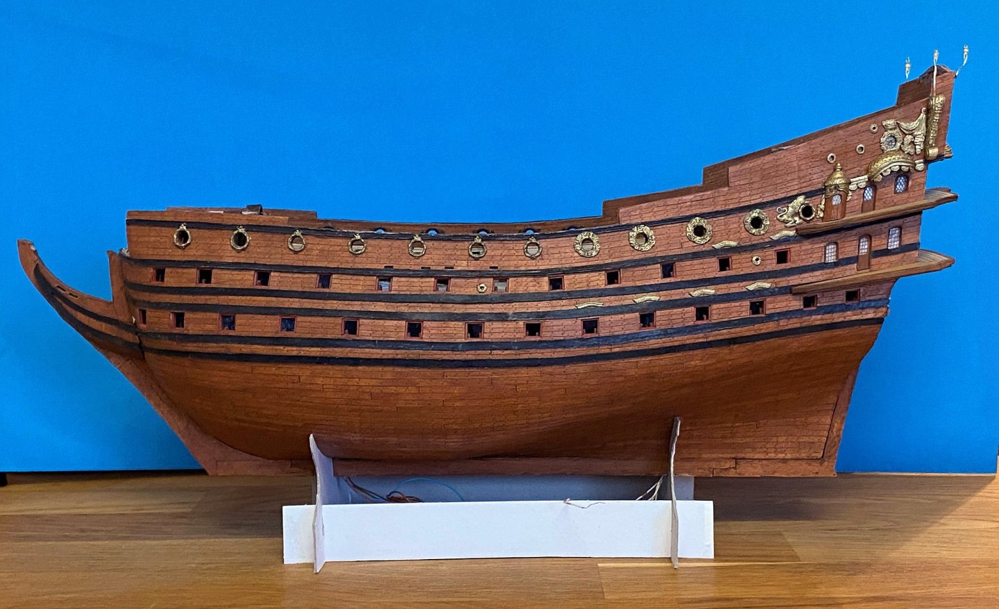
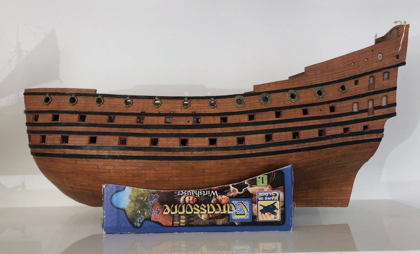
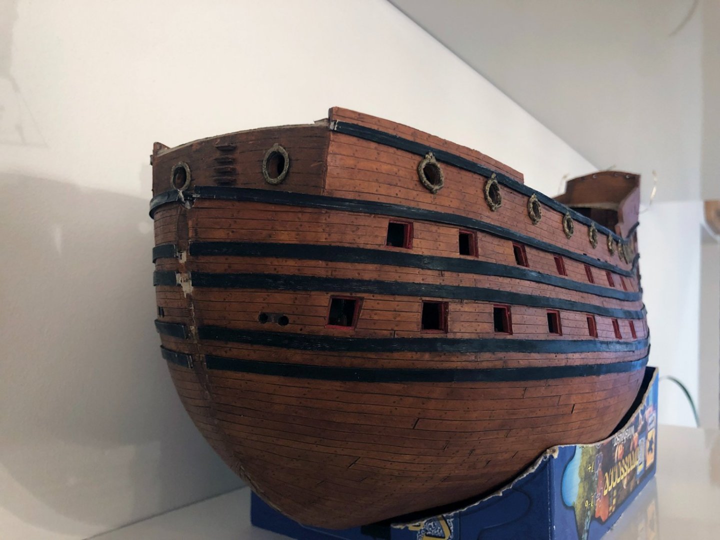
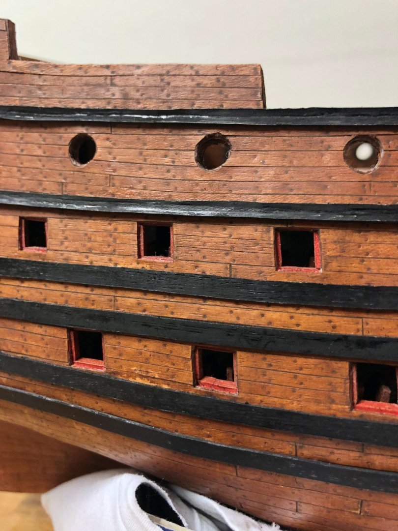
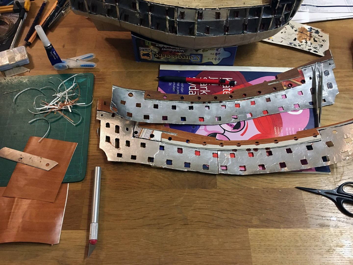
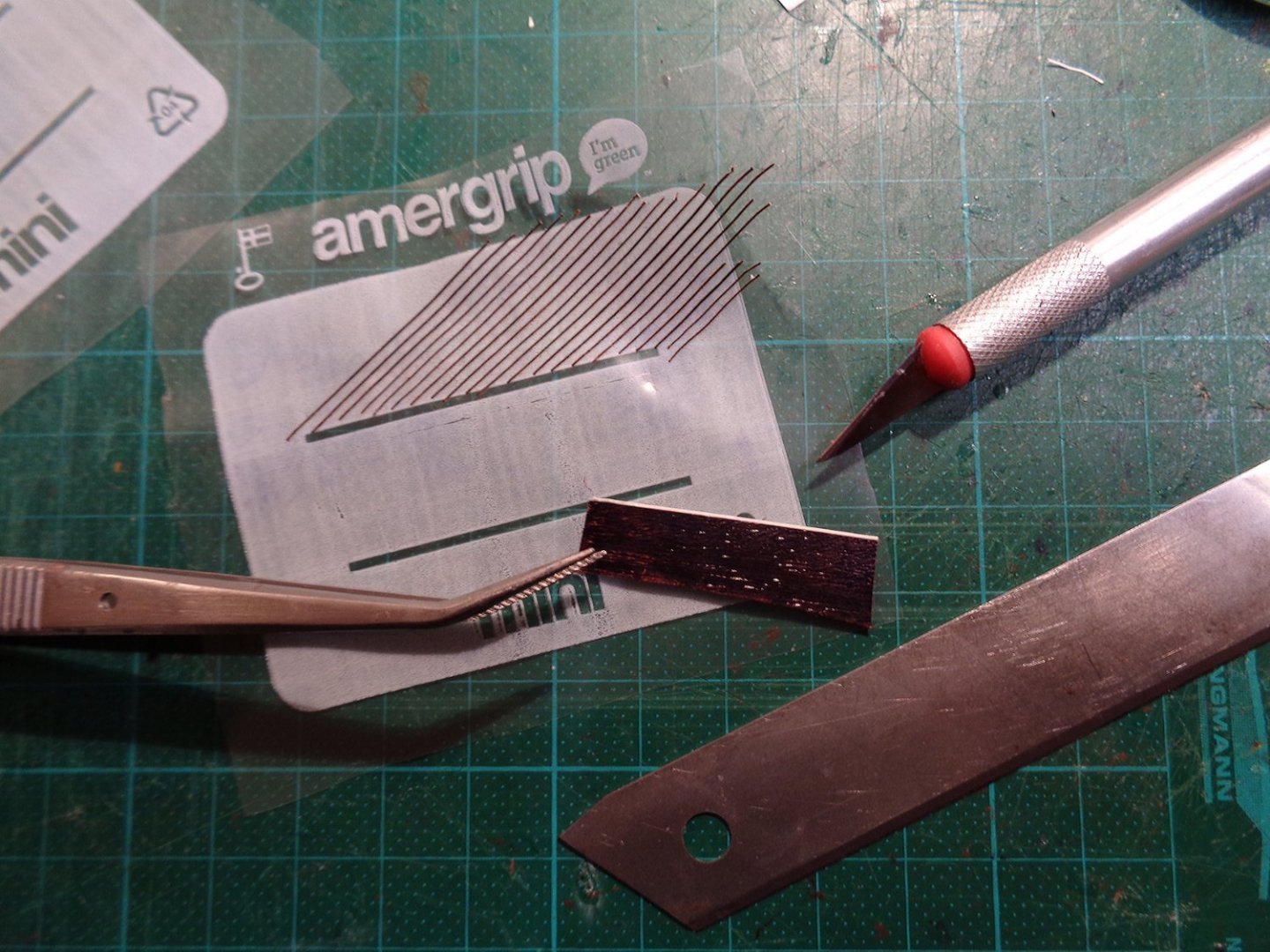
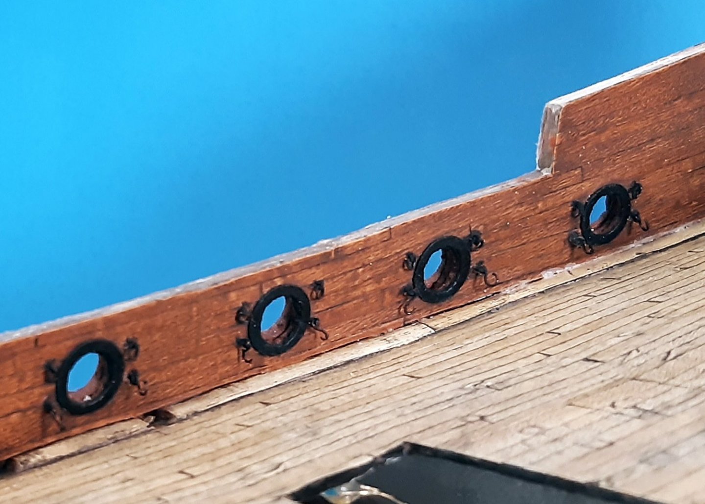
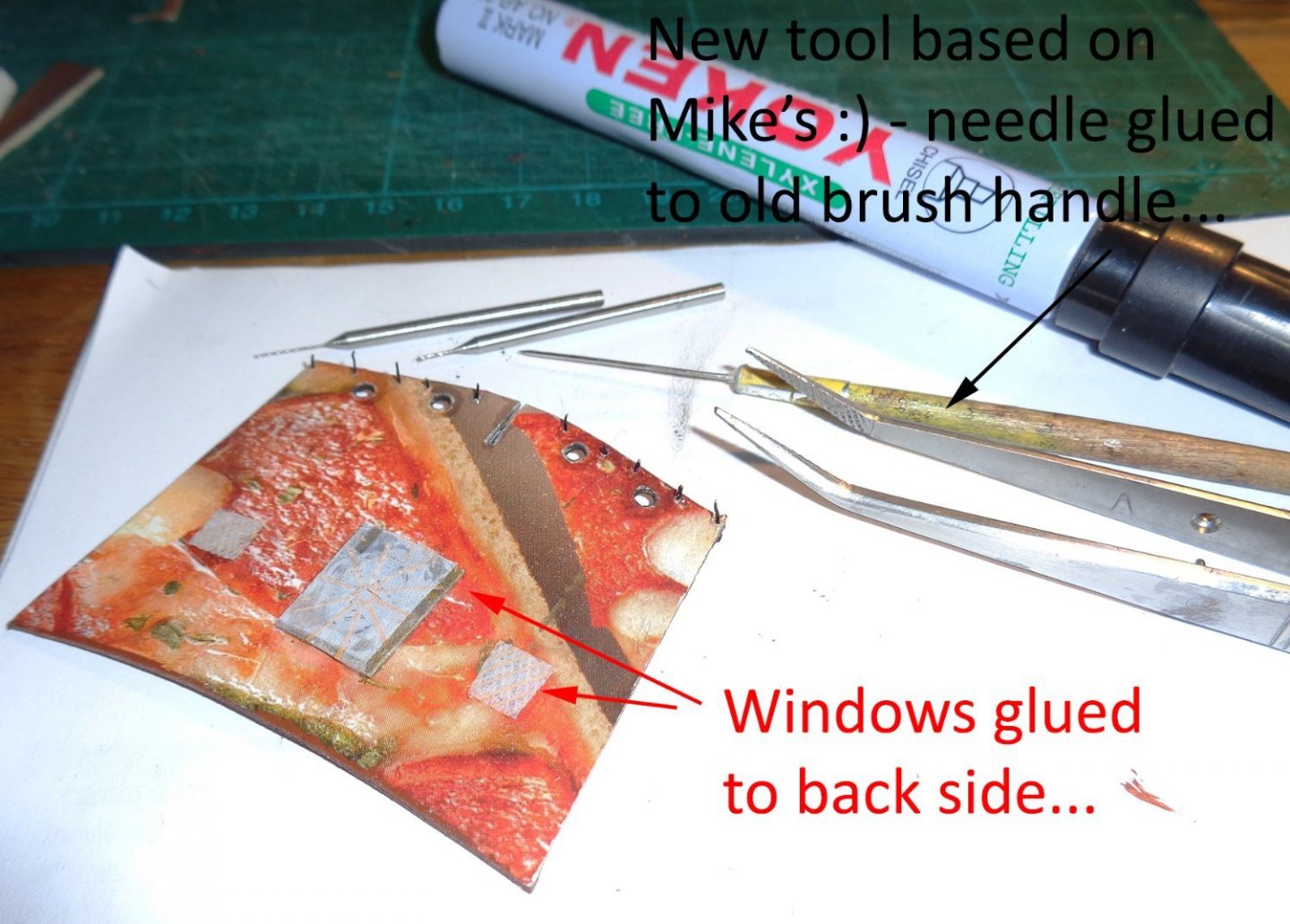
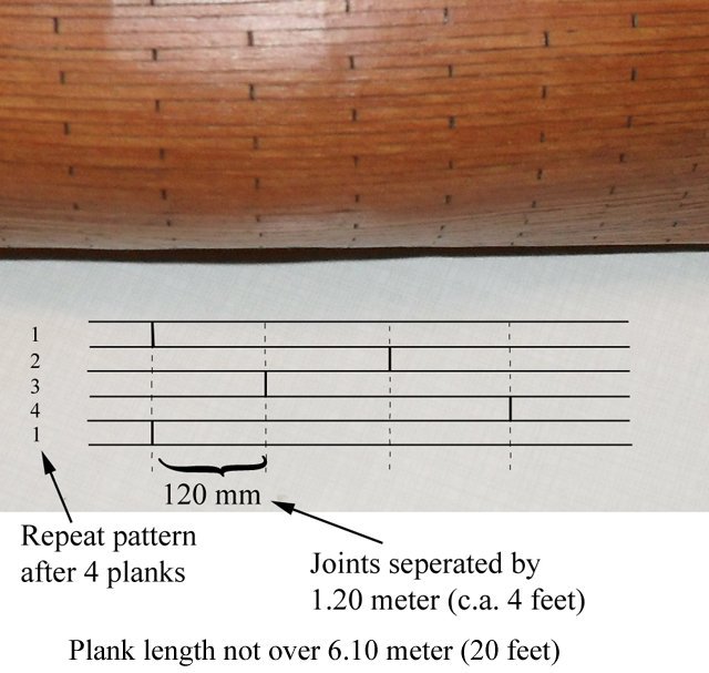
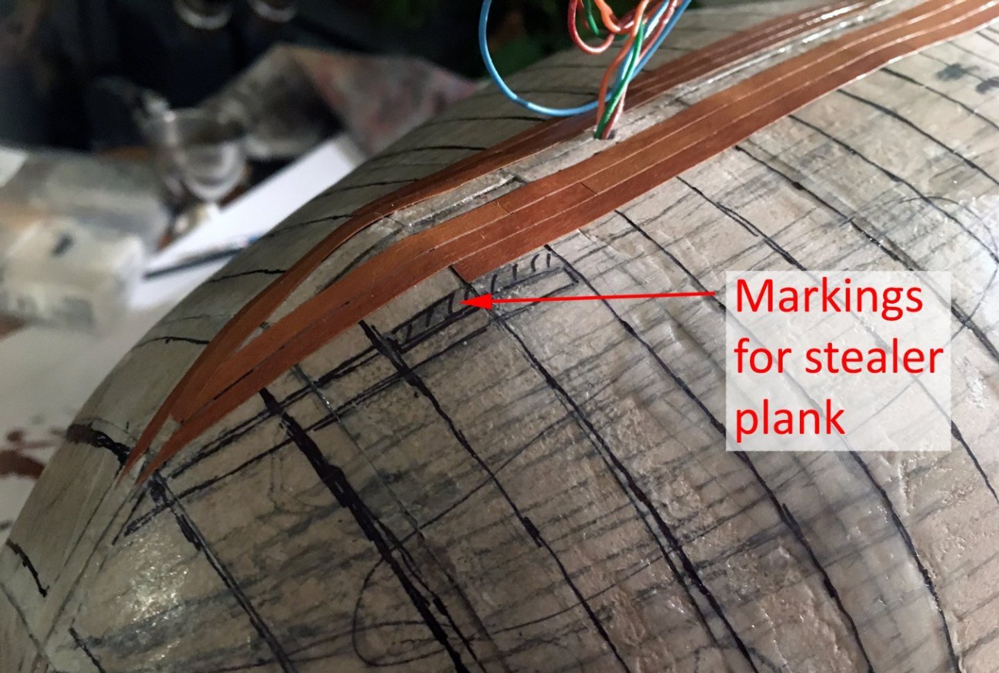
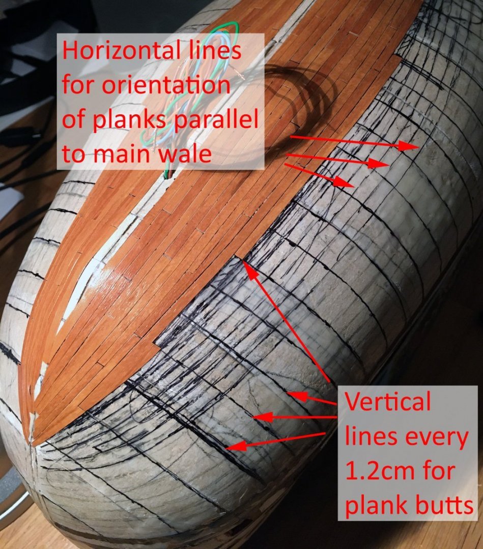
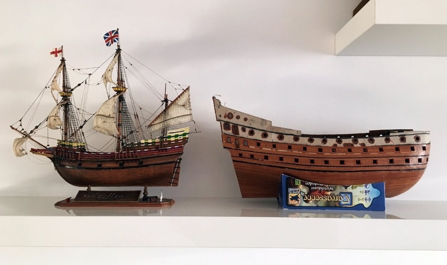
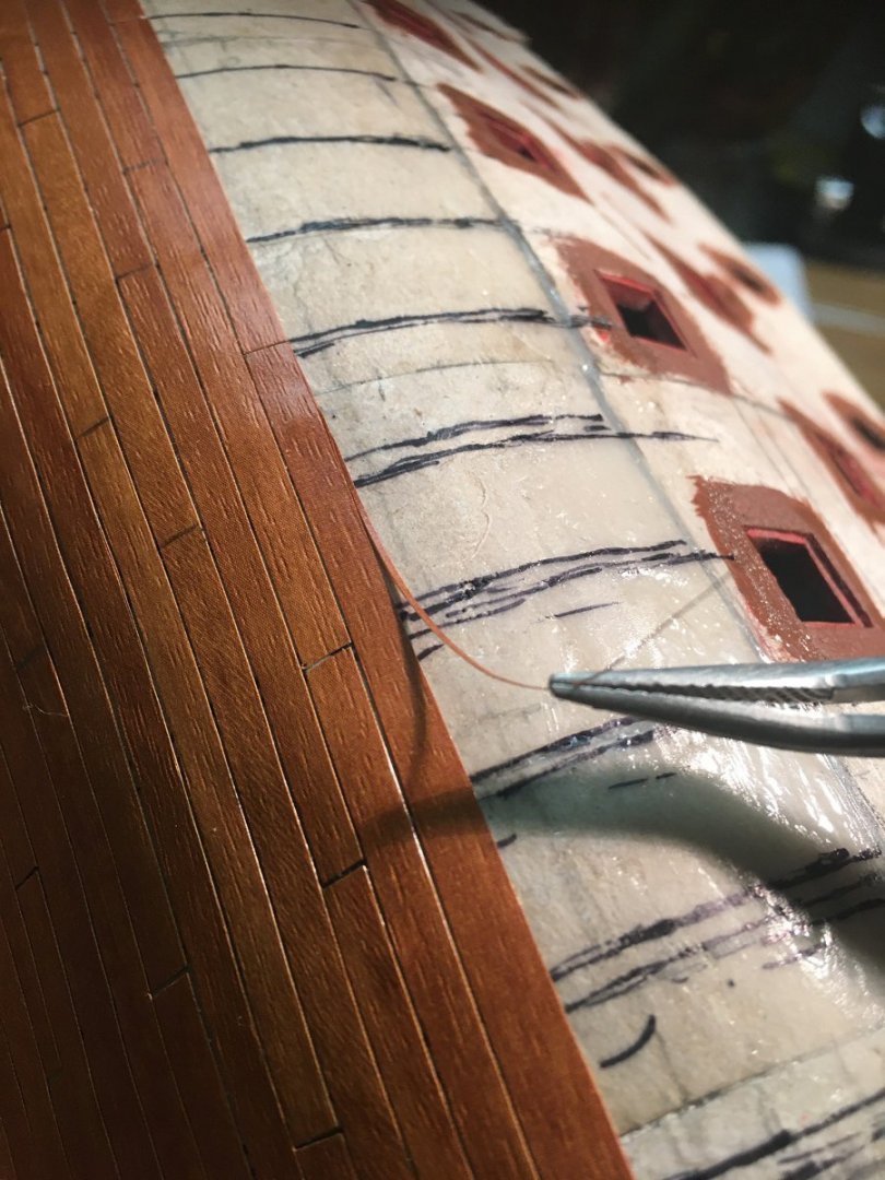
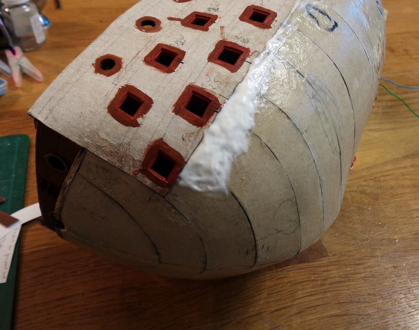
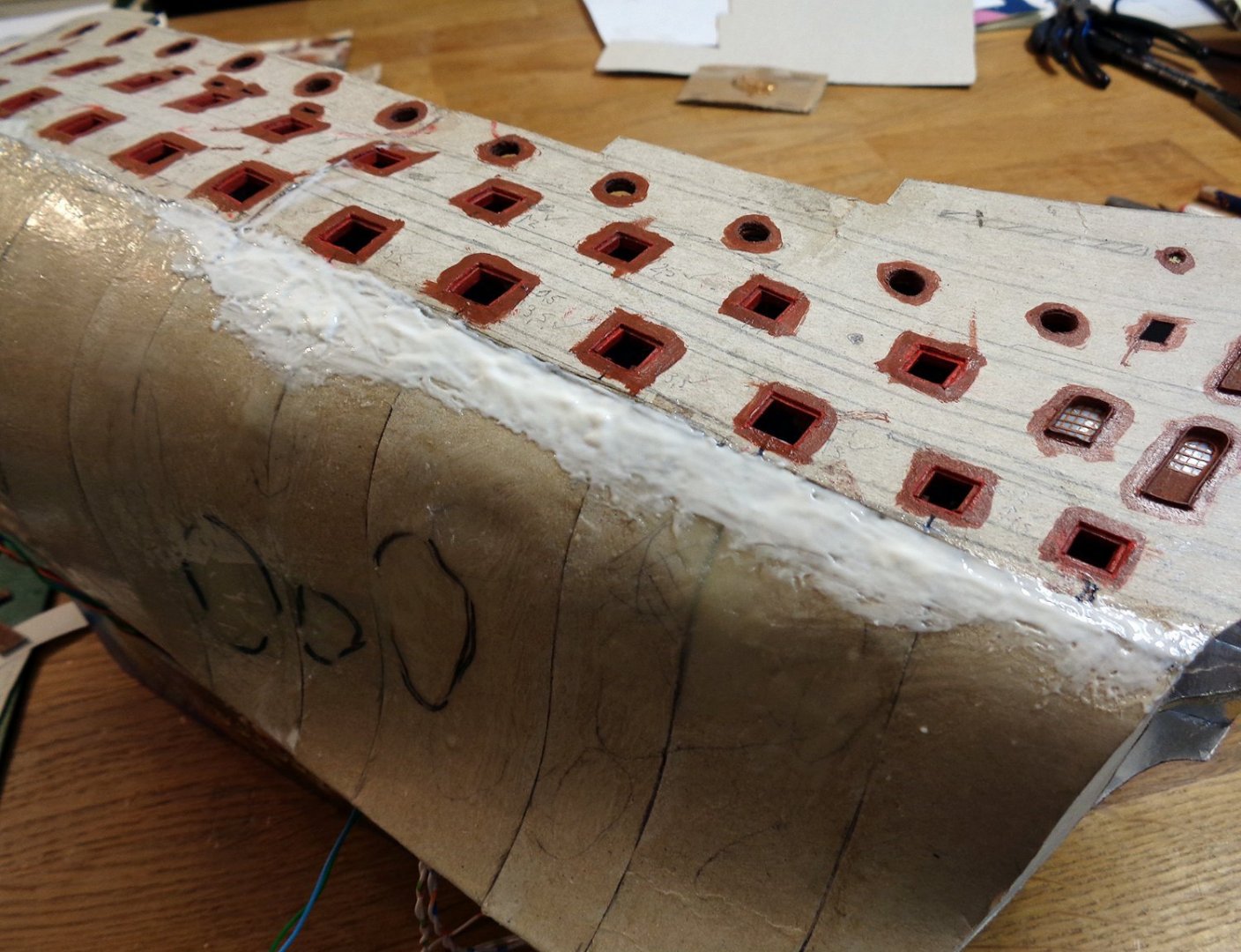
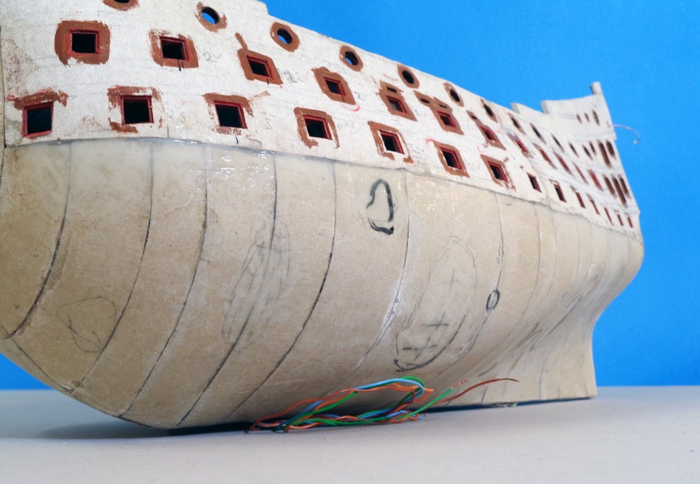
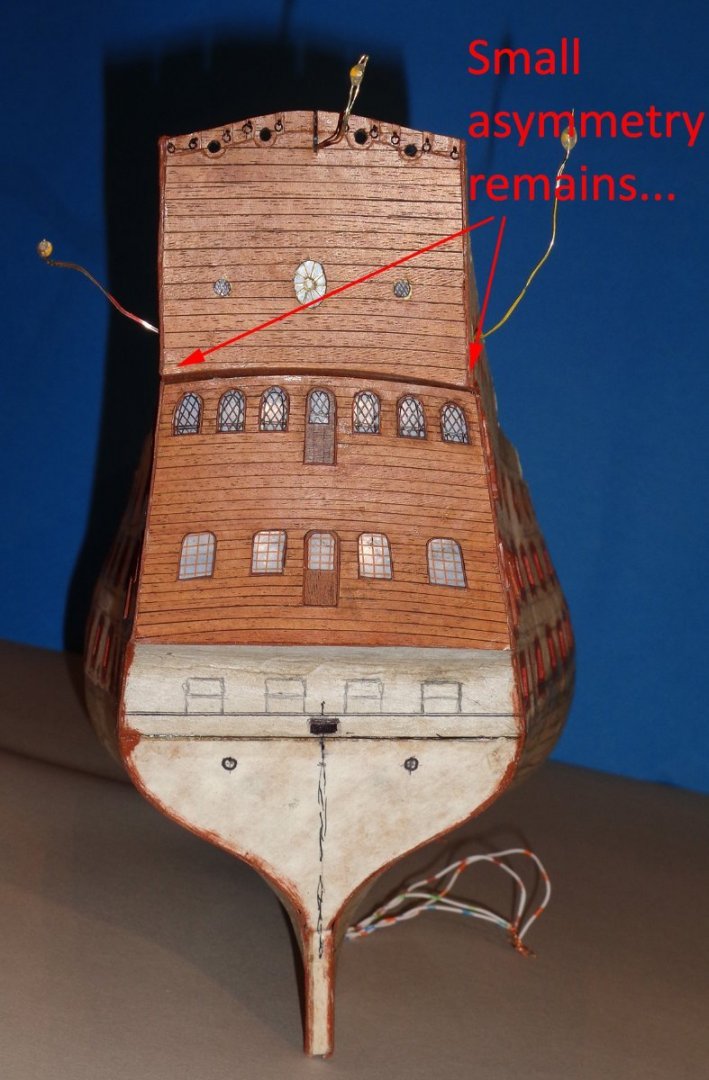
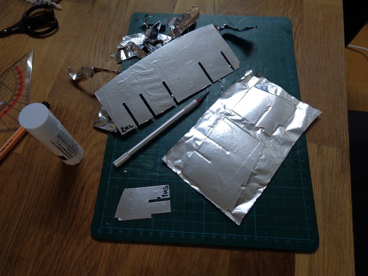
Hi there! I finished "planking" the ship, which is basically cutting out stripes of foil and glueing/attaching them onto the ship (then alter with oil paint - work in progress). But before I could do that, I had to make the sides of the ship and the stern parts. The side parts of the ship I made from my favorite frozen pizza box card (about half a mm thick) and glued some tin foil (aluminum foil) to the inner parts for better reflection of the (then still weak) LED light. The upper, visible inner part for the main deck was then added from two pieces, about 2mm thick card, each glued on top of each other. The next photo shows only one of these 2mm thick pieces. Then I used the foil for the "planking" of the inner part and altered with black oil paint. Unfortunately I was too keen on trying out brown oil paint on top of the already with black paint altered pieces before testing on some separate part and it got a bit of a dirty appearance in the end... The imitation of the thickness of the hull as visible in the gun ports I made with a thick card from excess parts for a tabletop game (Carcasonne ). I painted them first brown and then red (acrylic paint markers) by smearing the red paint off a bit to achieve a more "rusty" red instead of a clear shiny one. The results are satisfactory. In my next model I'll have to work on it a bit better, now I had quite some practice with this part of the build. Back to the top of the inner part I had to attach some black rings around the round gun ports as well as hooks and rings for the gun rigging later on. My apologies for the not so good pictures. I try to get better with it. The windows I made from some mini grip bags (because they are partly already covered with a semi-transparent white) and the foil painted black (and gold for some windows), cut in tiny strips. I remember DORIS once telling me they can be cut even as thin as a hair. So I tried my best to get them tiny enough for the windows. I did the windows fo the stern part in the same fashion, using a tiny card strip painted brown (acrylic paint marker - or pen) for the frames. Then, after all pieces were glued in place (with quite some struggle...) I could start with the planking. For that I used the foil with a width of about 2-3.5mm, representing planks of about 20 to 35cm width (or about 8 to 14 inches). The length of each plank should be about 4.8cm (or double that length where I later cut the plank butts with a knife) and a pattern every 4 planks with a distance of 1.2cm between plank butts (about 4 feet). I used the same pattern on my model of the Mayflower. This image is from the Mayflower build: I found this pattern somewhere here on Modelshipworld.com back then when building the Mayflower. This is an awesome forum to find a lot of information - Thanks everyone! Now, this is surely not a representative pattern from the 17th century, but for my eye it looks good on the model. Of course I struggled with the stealer planks to keep the pattern, and in the bow of the ship the length of the planks differ form the pattern. There the planks should be anyway a bit longer, to achieve a stronger hull against the forces of the water. Also, looking at the planking as documented from the Swedish Vasa ship (although we should not base our whole interpretation on only one wreck), there was not really any beautiful planking pattern. And even the symmetry is rather fiction than reality, as Fred Hocker wrote in "Interpreting Shipwrecks. Maritime Archeological Possibilities" (2013, Södertörn Academic Studies 56, Southhampton Archeology Monographs, NewSeries No. 4) in his sub-chapter "The myths of symmetry and regularity". I tried to be as symmetrical as possible, starting to plank from the keel upwards (contrary to the common way of planking from the main wale down in addition), but somehow ended one plank more on the larboard side... Sometimes I had to taper the planks after I attached them to the model. Tricky, but not impossible... Size comparison with the Mayflower, both models in scale 1:100 (in cm). The part around the windows was especially tricky for me... So much for now. Next post then about the altering of the planks with oil paint. This time I used brown burned umber instead of black and decided to imitate tree nails on this model, just to practice and see if I "screw it" completely or "nail it"! I am satisfied with the tree nail experiment (to me it looks more like nailed rather than screwed ), but more on it in the next post. Right now I am finishing doing them and altering with the oil paint, before glueing the wales in place. See you around! -RdK


-
Hi there! Nice tool collection. How do you and other people cut the needles so nicely? I tried with standard pliers but that only squeezes the needle at the point where I cut it. Also, yes Tomasz, I grew up with Maly Modelarz as well. Rgds, Radek
-
Hi there! Tomasz, this certainly does not look like your first. Really enjoyable thread about your progress! Great work! I also had a bit of trouble with rigging my Mayflower (gallery here) and Anderson was the way to go. I really like the sails you made. Bravo! And Kirill, thanks for sharing your knowledge and the useful links! Rgds, Radek
-
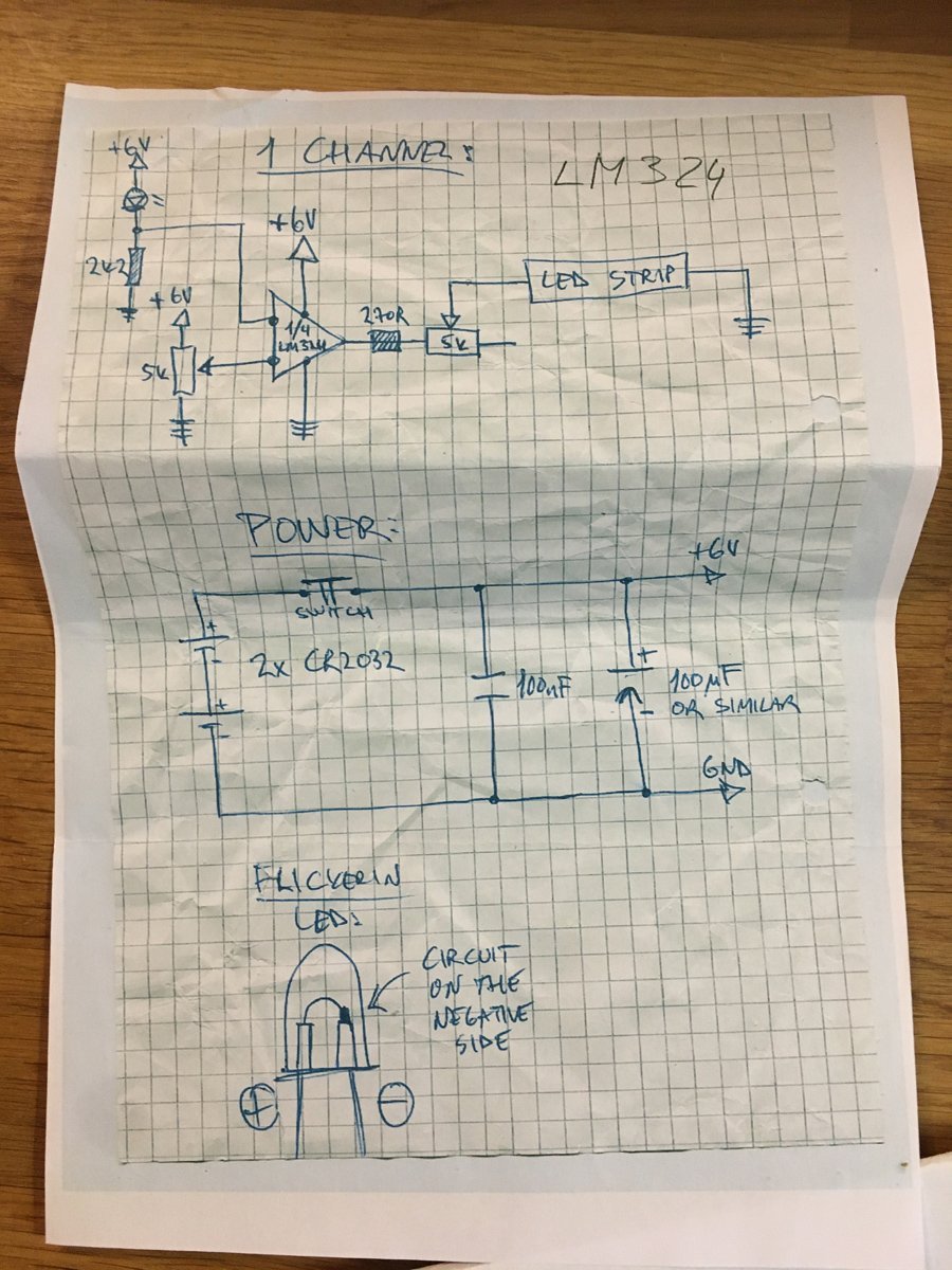
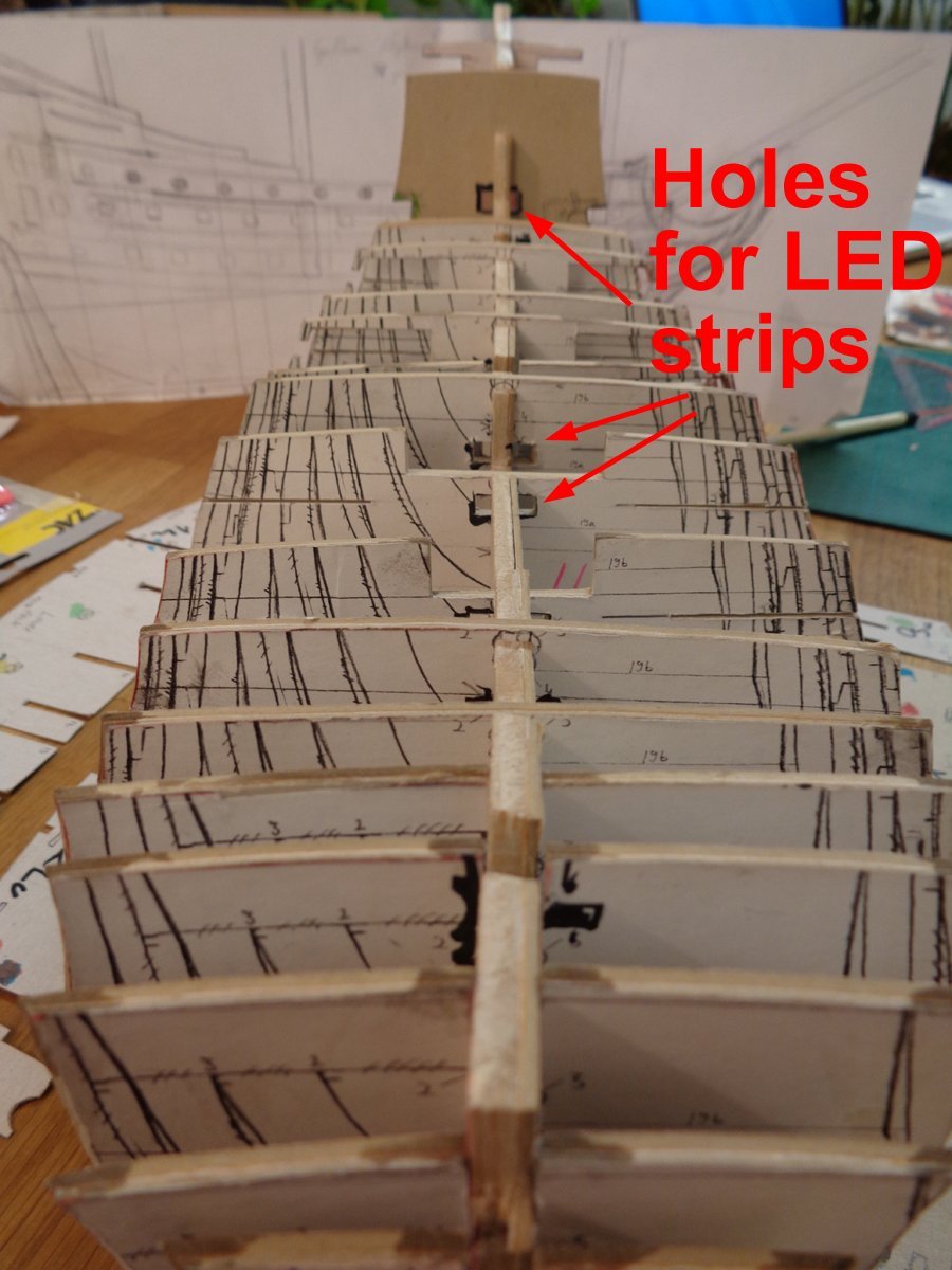
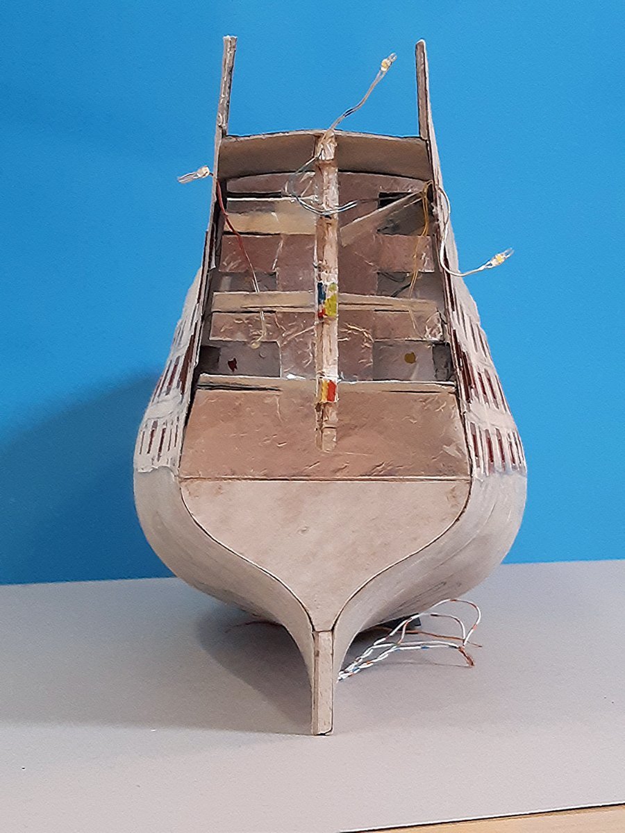
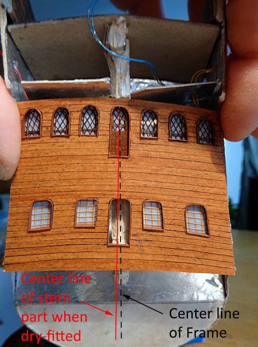
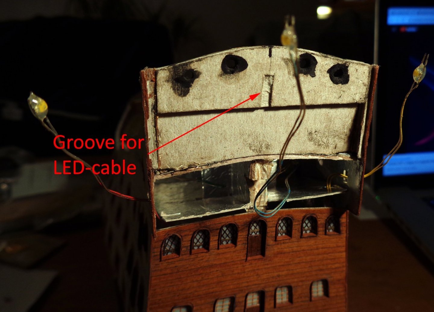
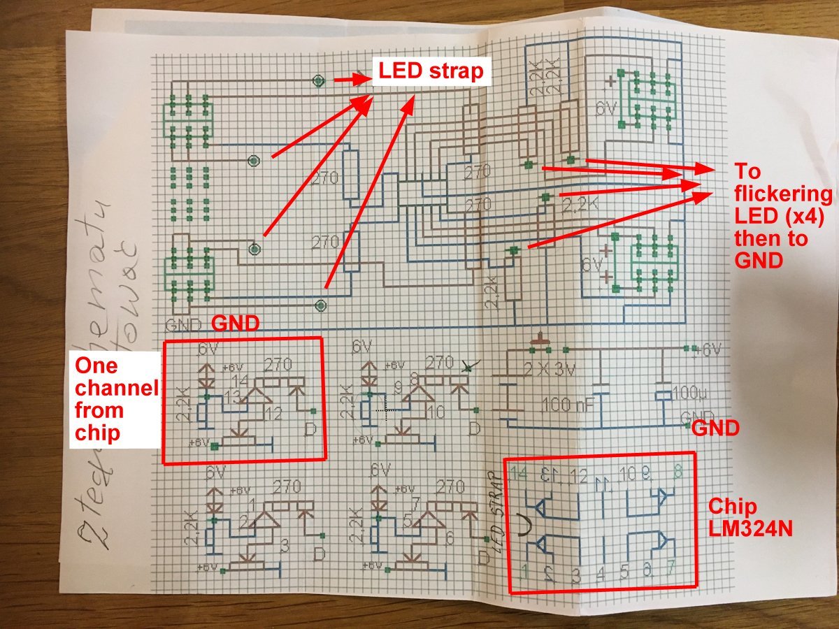
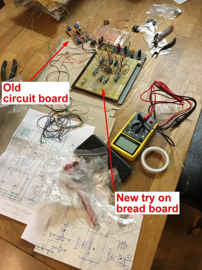
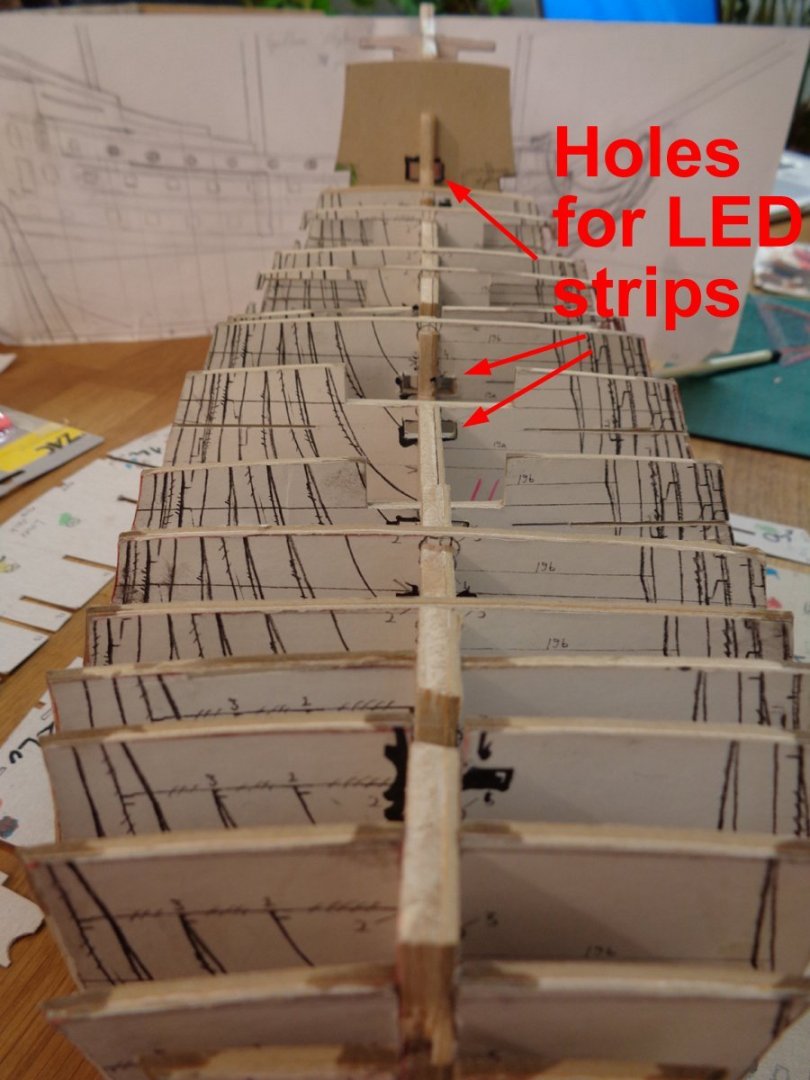
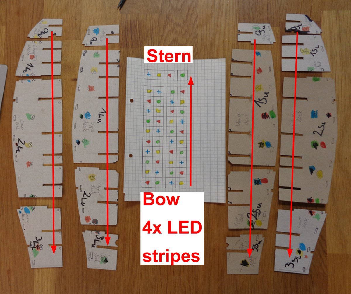
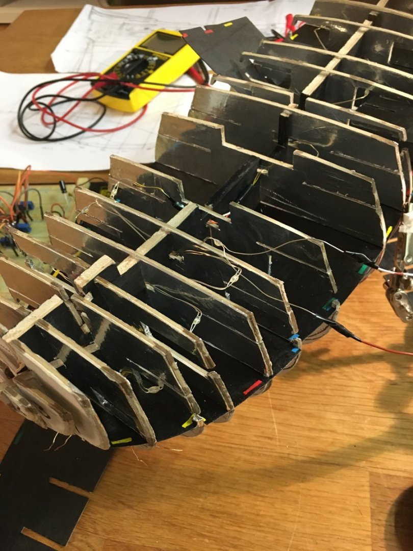
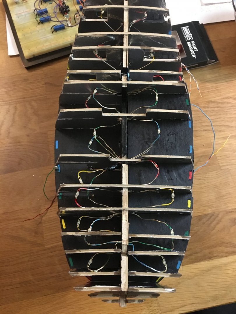
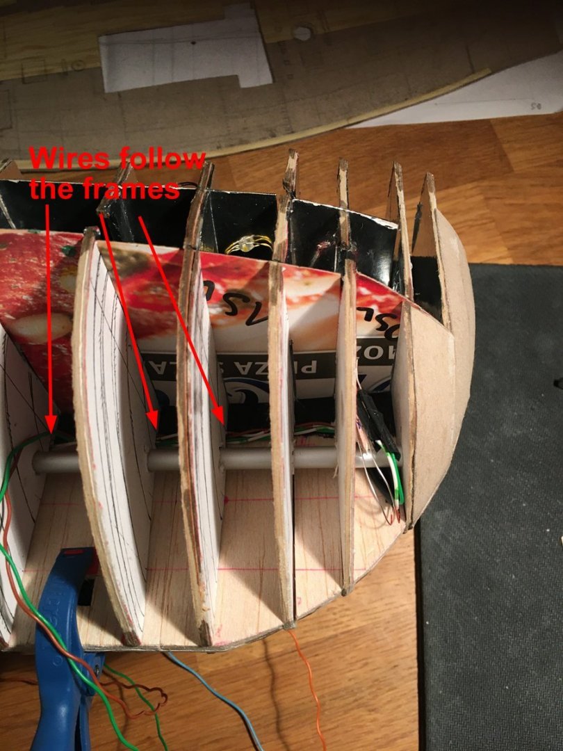
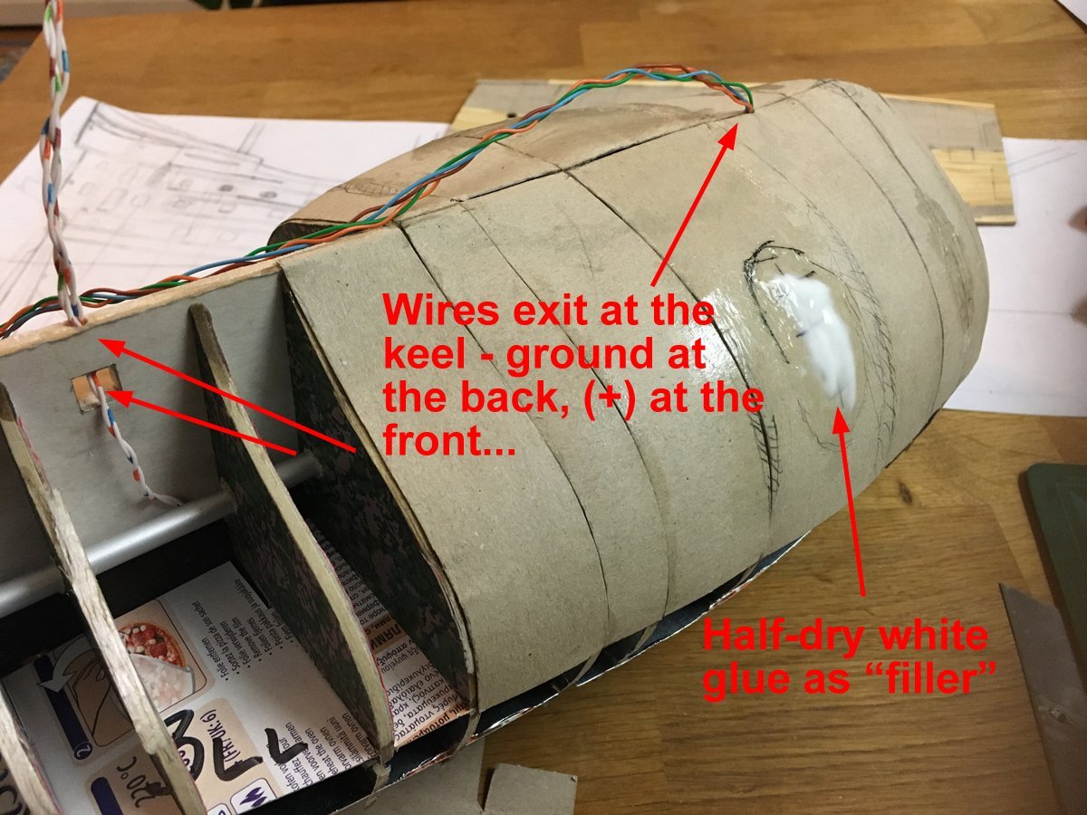
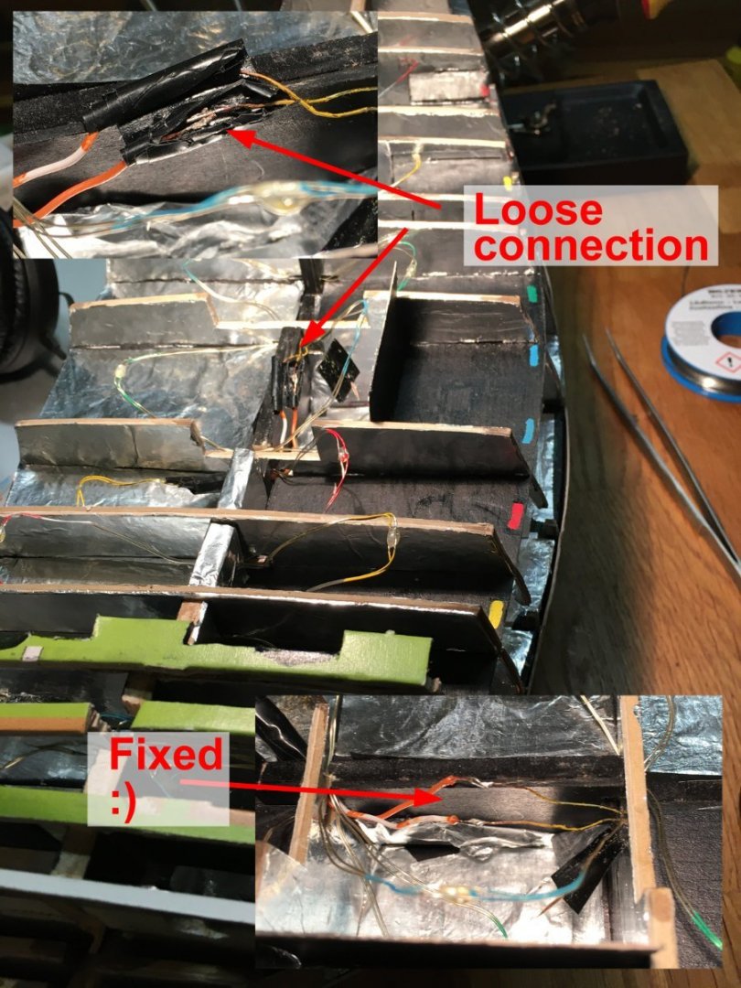
Hi there! Thanks for your likes and comment! Much appreciated and encouraging! Yes, making a scratch build without any plans whatsoever available makes many steps feel like steps backwards... A lot of corrections because I was not thinking far enough ahead. But I am not such an experienced ship modeler and this is all valuable experience I collect. The LEDs that flicker like candles were made with the help of a colleague at work, who is experienced in electronic schematics. My idea was to take those single flickering candle-LED lights, four of them, and use their flickering circuit to distribute the flickering to an LED-strip of 10-12 LEDs. These strips are easily available especially during the winter time. The idea to use only four different flickering frequencies along four LED strips came because in scale 1:100 (centimetre) there is not much room to install a resistor in front of every LED in the model and in addition I did not want to have a lot of soldered parts inside the model itself (it is card and paper after all...). My colleague at work came up with the schematics by using a chip with four channels to distribute the 4 candle-LED circuits onto the four LED-strips. I asked my father to help me put this plan onto a circuit board. And after my initial attempts to solder the circuit board with cold solder and everything possible going wrong, my father (who is an electrical engineer) suggested I try it out first on a bread board. The parts needed for the circuitry are: -4x LED with in-built random flickering circuit -1x long LED stripe with 40-50 LEDs (during Christmas time everywhere available... ) -1x LM324N chip or ic (and a socket for it, makes soldering life easier) -8x 5 kilo-ohm potentiometers -4x 2.2 kilo-ohm resistors -4x 270 ohm resistors -1x 100 nano-Farad capacitor -1x 100 microFarad electrolytic capacitor -1x ON-OFF switch -2x 3V batteries and battery-holder I replaced the battery with a 9V battery, becuase 6V were not enough and the flickering stopped after 10 minutes. Since the weakest capacitor goes up to 12V, I could also attach 12V but 9V are sufficient. I figured that out only much later in the process. I ended up using 3x 11 LEDs and 1x 10 LEDs on the strips. I wanted to have one going all the way up the mast for a lantern there, but somehow during the building break I totally forgot about it and did not pursued that idea anymore. Maybe another time... I also had to change the frames by cutting holes where the LED-strip would go through. I also wanted to set up the four strips so that no same frequency LED-strip would be next to each other visible through the gun ports and the individual compartments between the bulkheads. Then I had to pull the strips through the holes somehow. It was not as easy as I imagined, but it worked. I did not pay much attention to align them nicely, because they won't be so visible afterwards, Just tried to make sure they are about centered in the compartments and not directly visible when looking directly through the gun ports. In the next photo you can see the wires for the ground (white-colored) and plus (colored) going through the frames underneath what is the lower (pizza-) gun deck. Also you can see that I stabilized the frames with an aluminum rod next to the center frame (on both sides). These wires exit the hull through two holes and will be later connected to the stand: And next time I will not use any half-dried white glue as "filler", but will buy a proper one (although not for model making). I had to extend the LED strip in one part of the ship, which led to a shortcut that I had to fix later on again. So far all LEDs are lit and my surgery seems to have been successful... I will try to make a better video of the lit model and post a link here. Here's the half-dried "filler-replacement" glue in action: And after quite some sanding it turned out good enough... ..."Smiling faces"... Then I closed the hull by making the stern part, which was quite asymmetric to begin with. I tried to even it out a bit. At the moment I am planking the ship with the self-adhesive foil (the one DORIS is using for her models). But more on the stern windows and the planking in the next post. So much for now. Stay safe everyone! Rgds, Radek


-
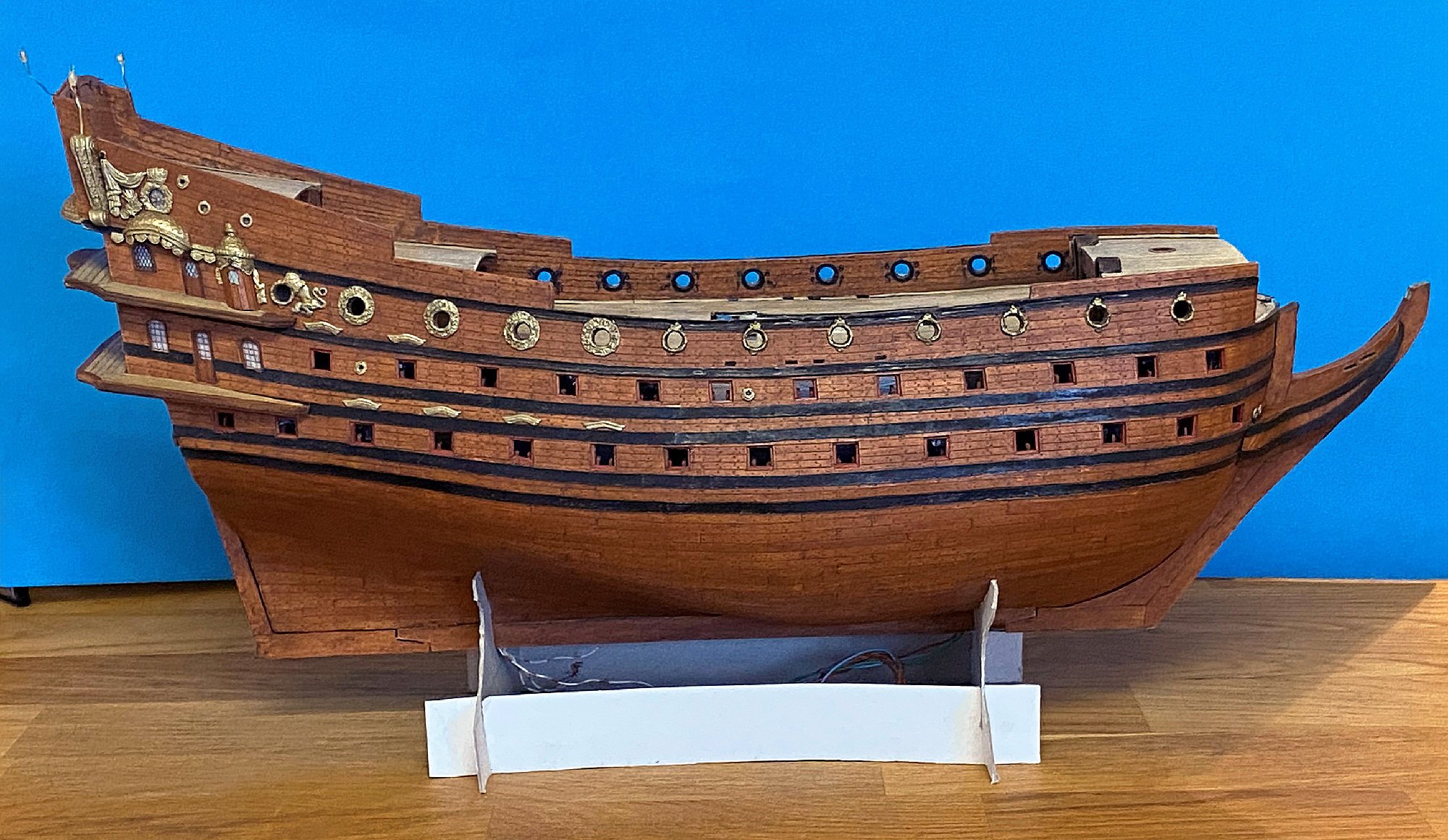
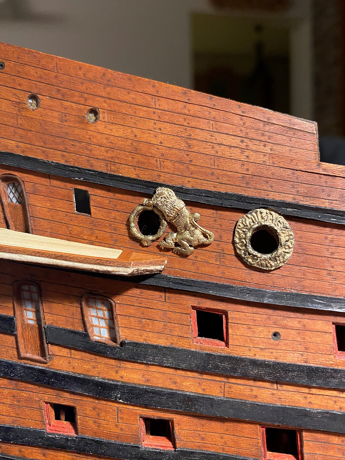
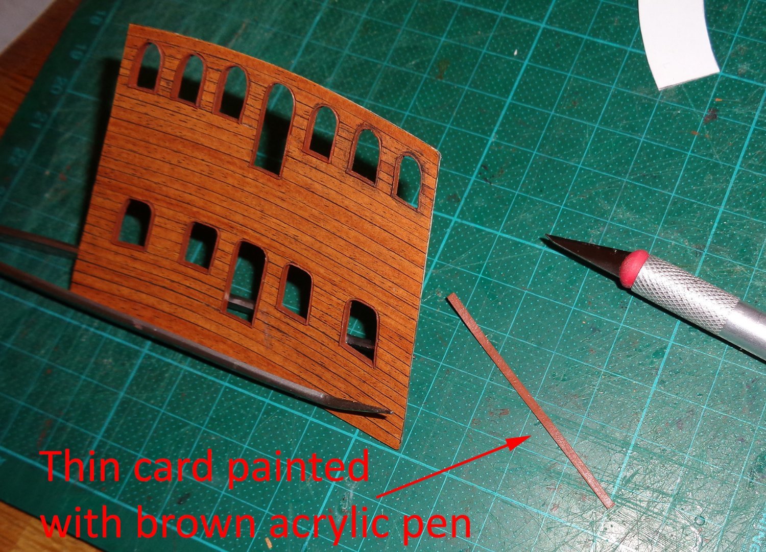
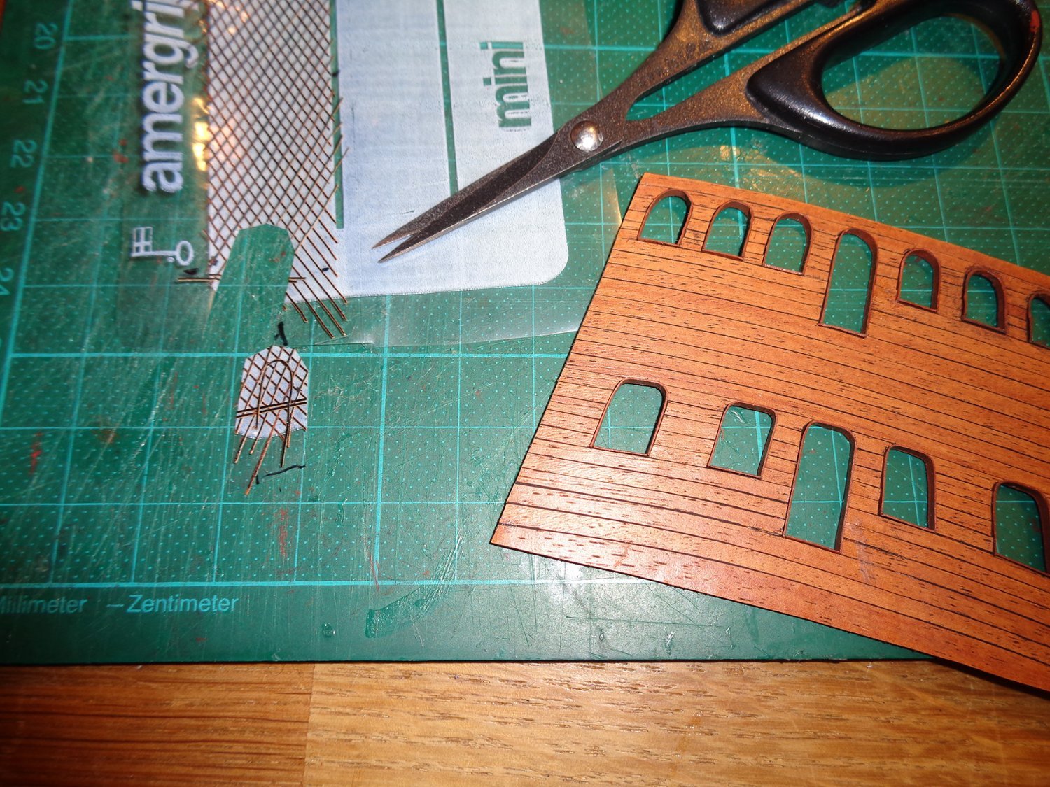
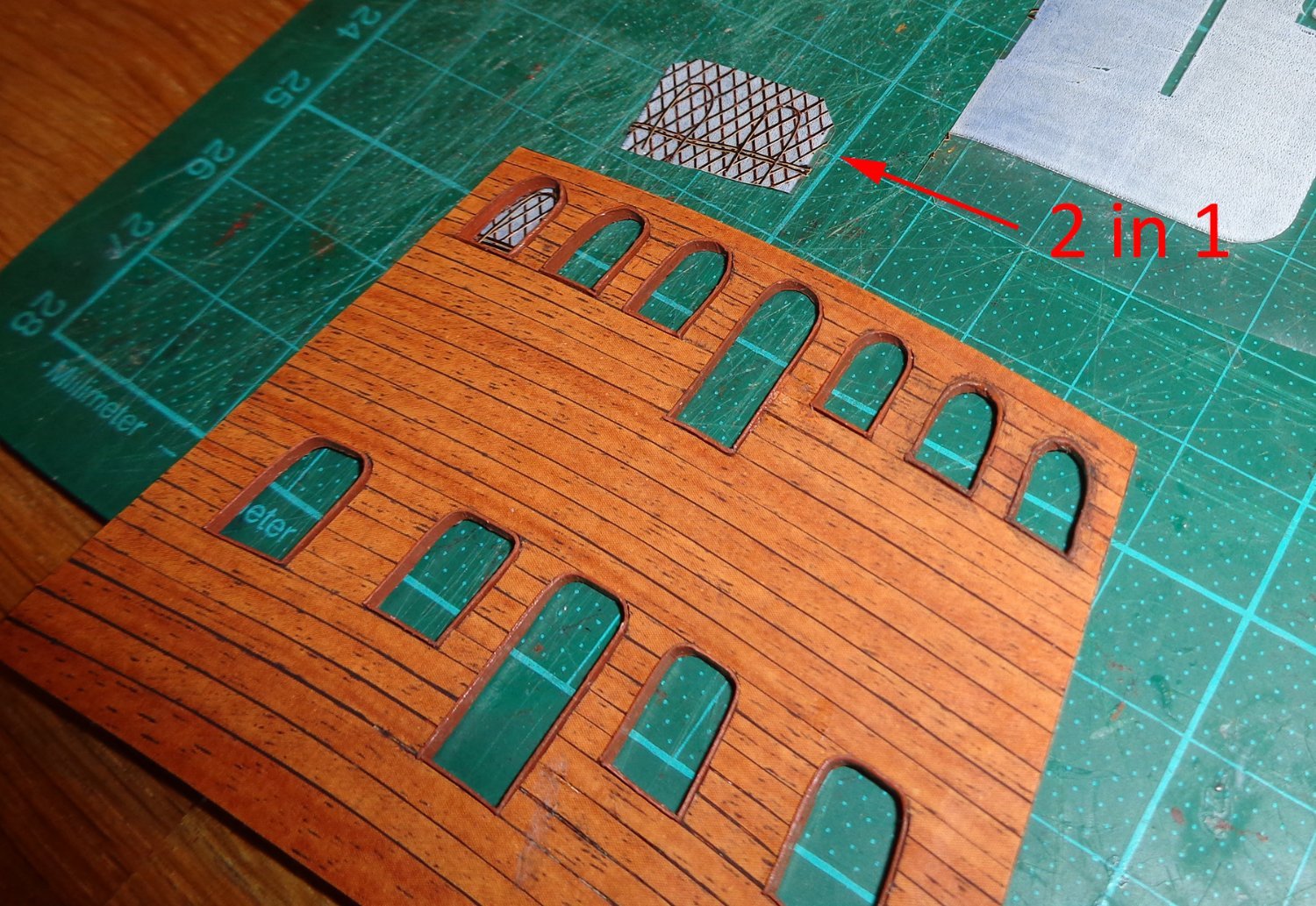
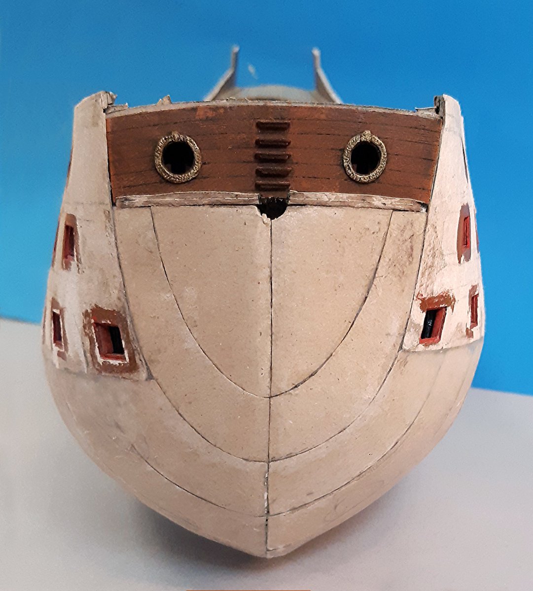
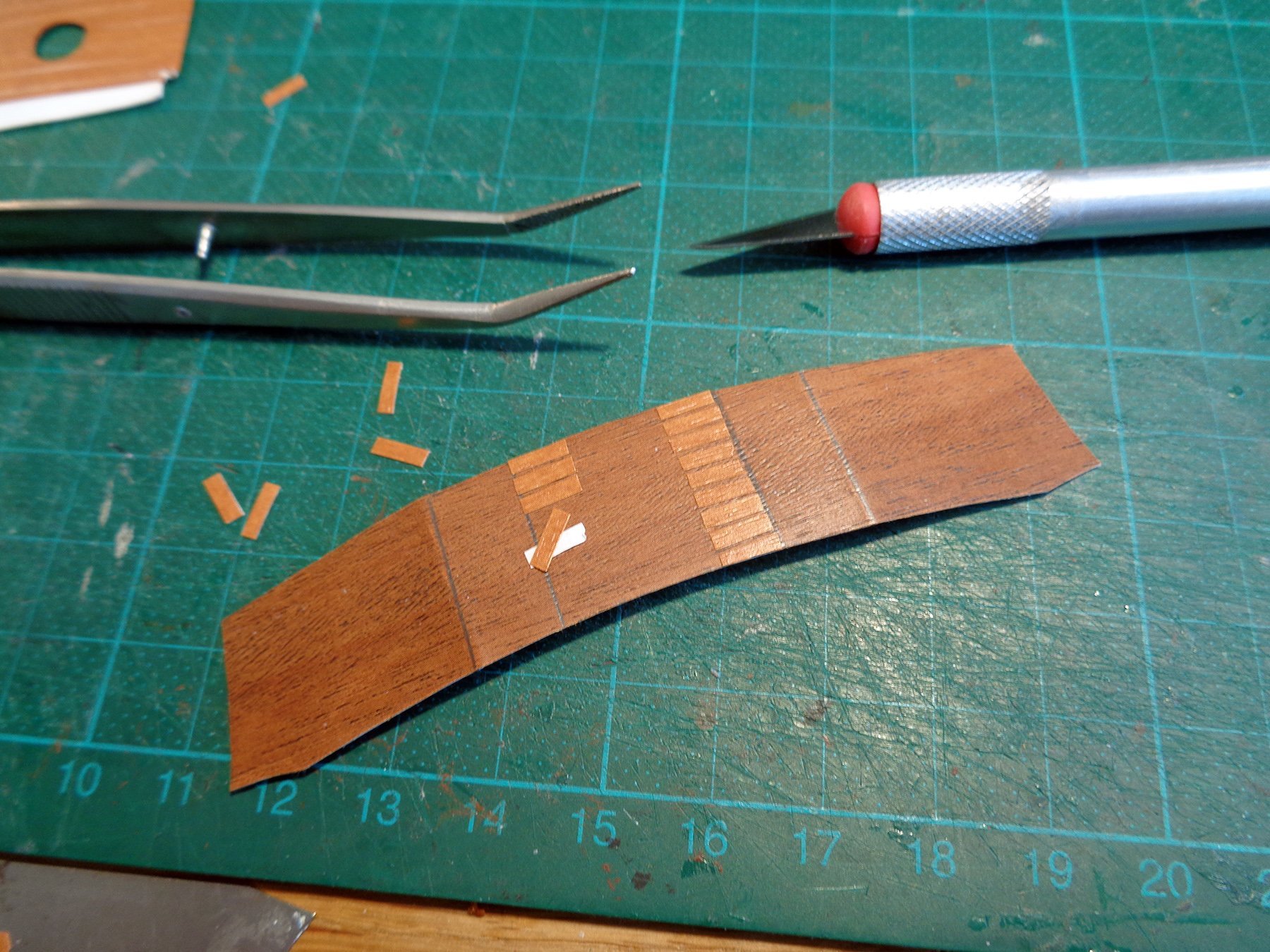
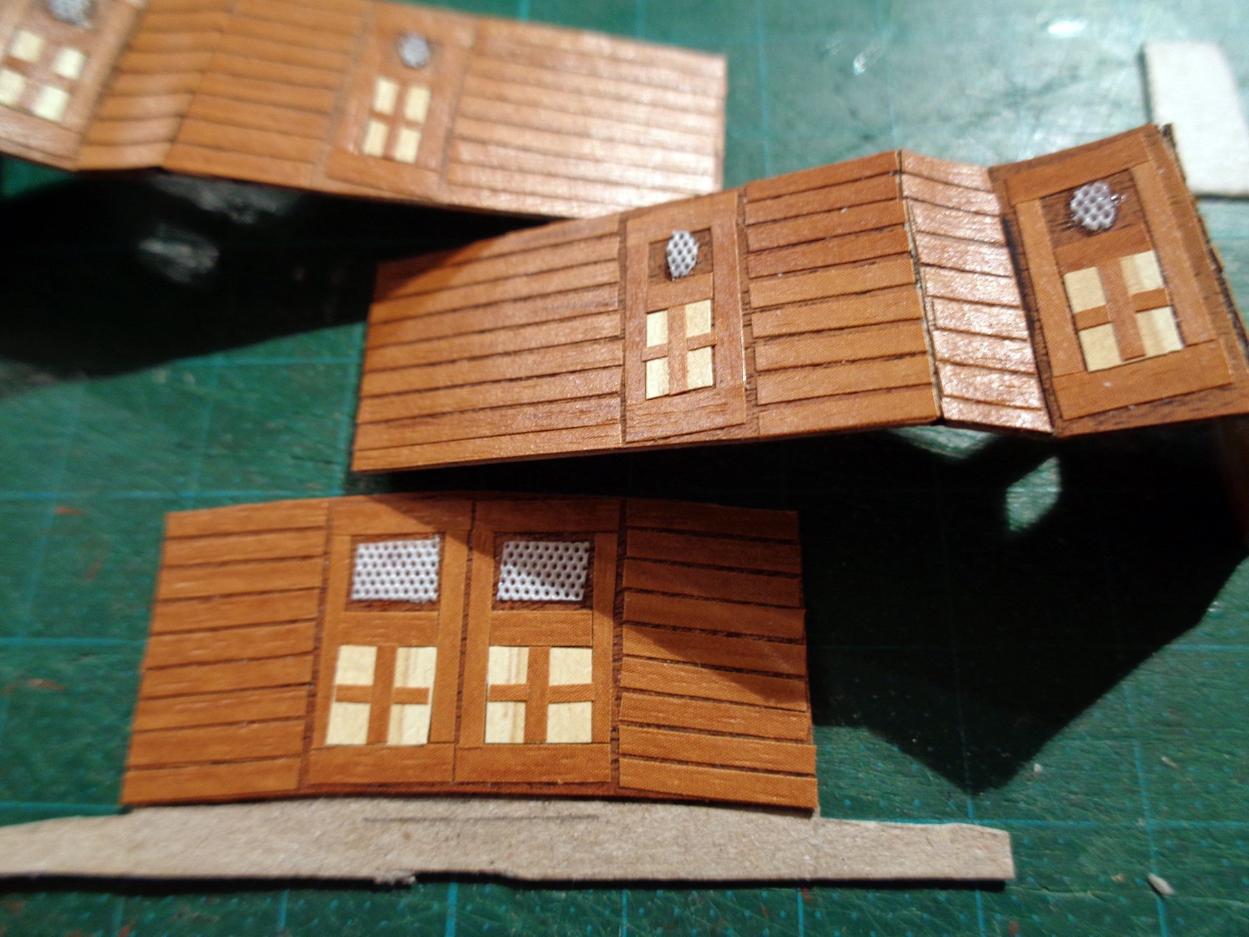
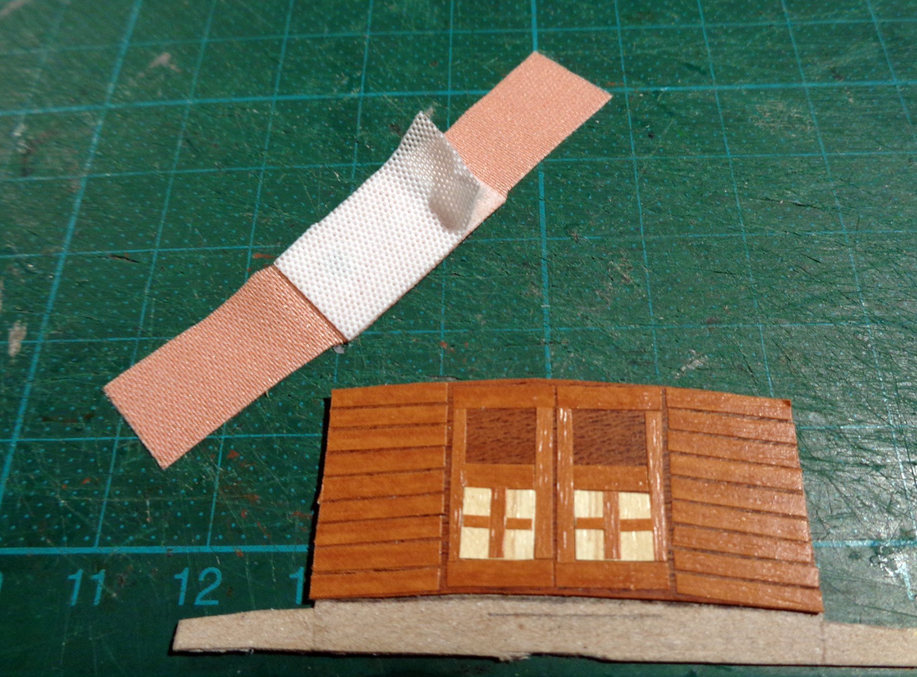
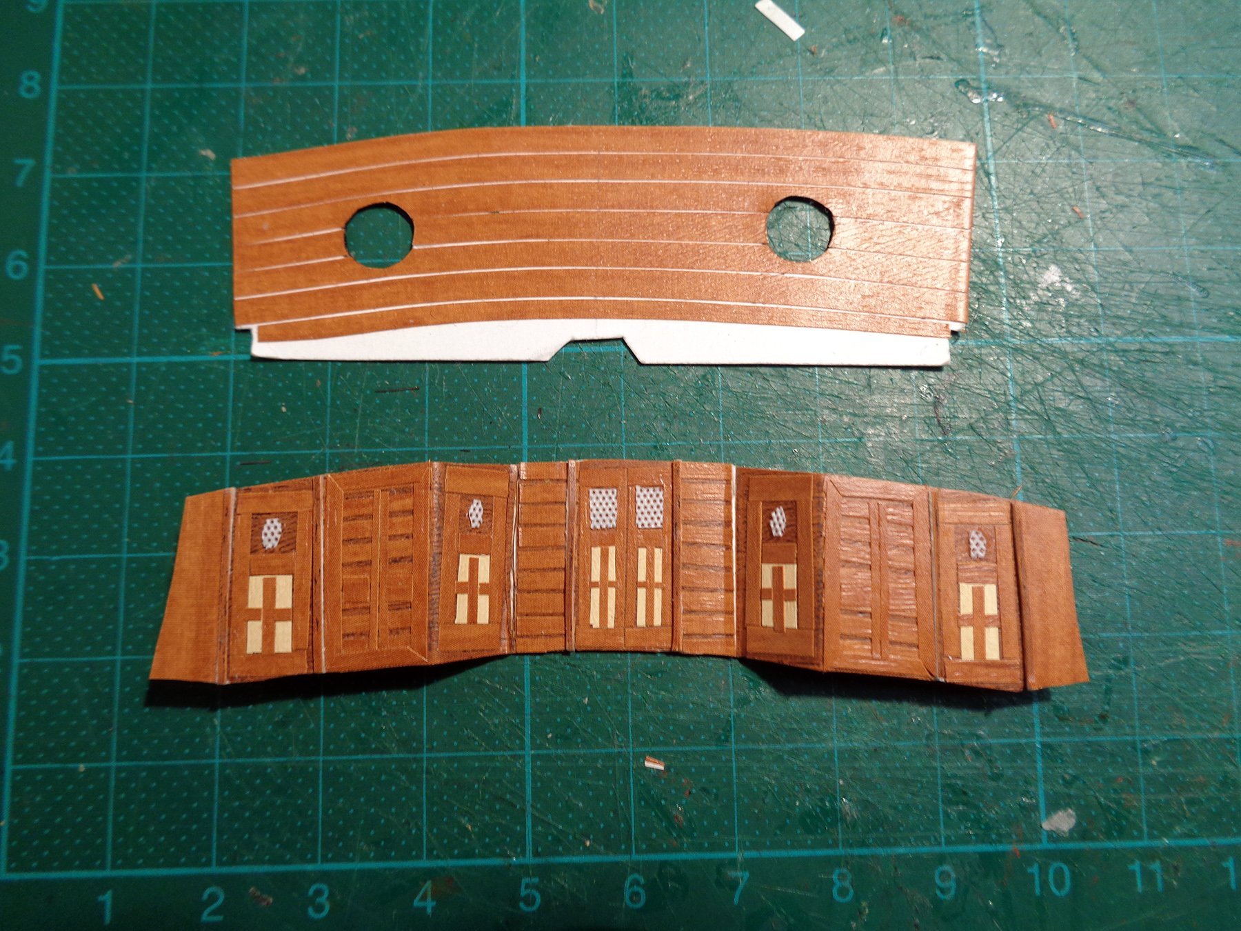
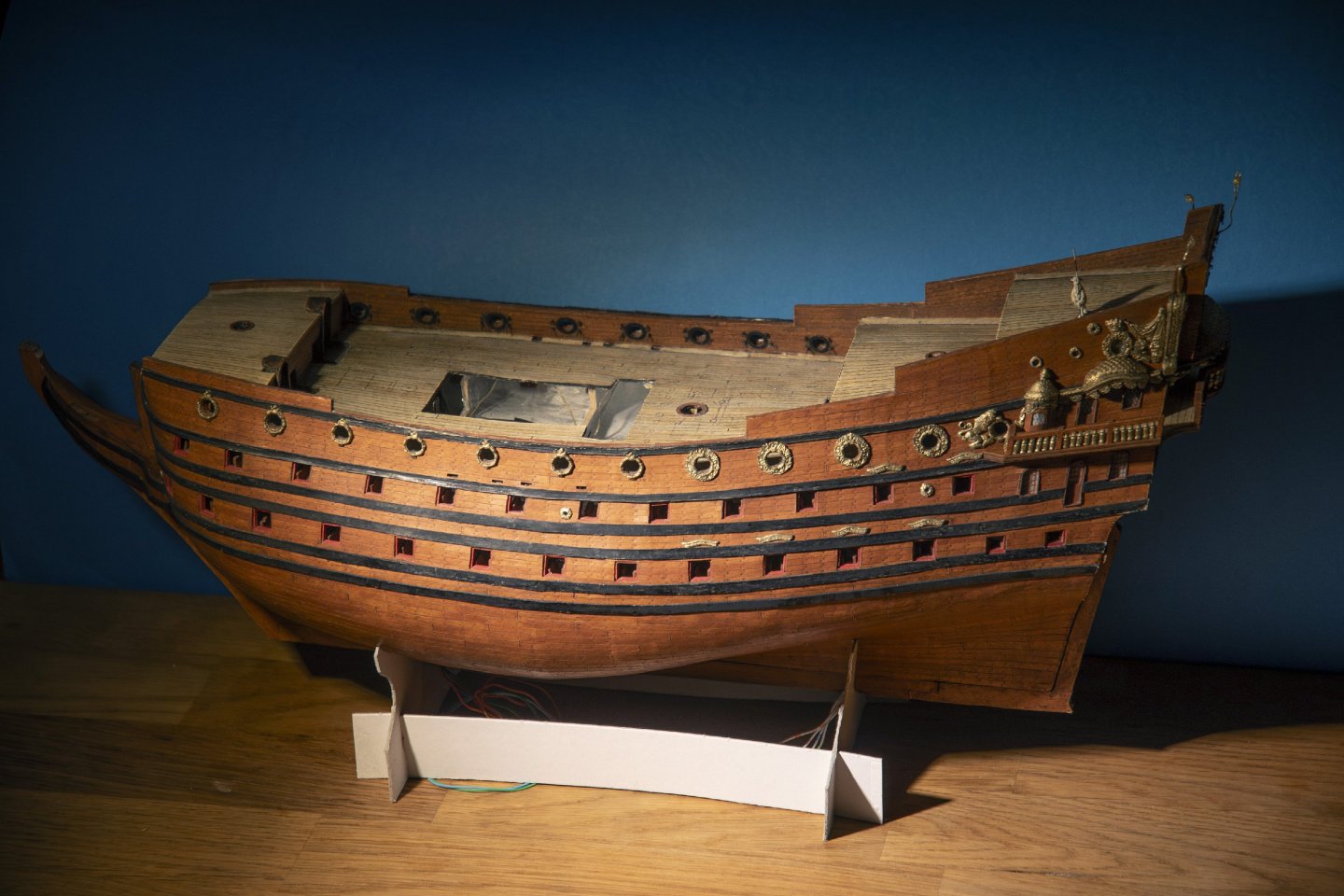
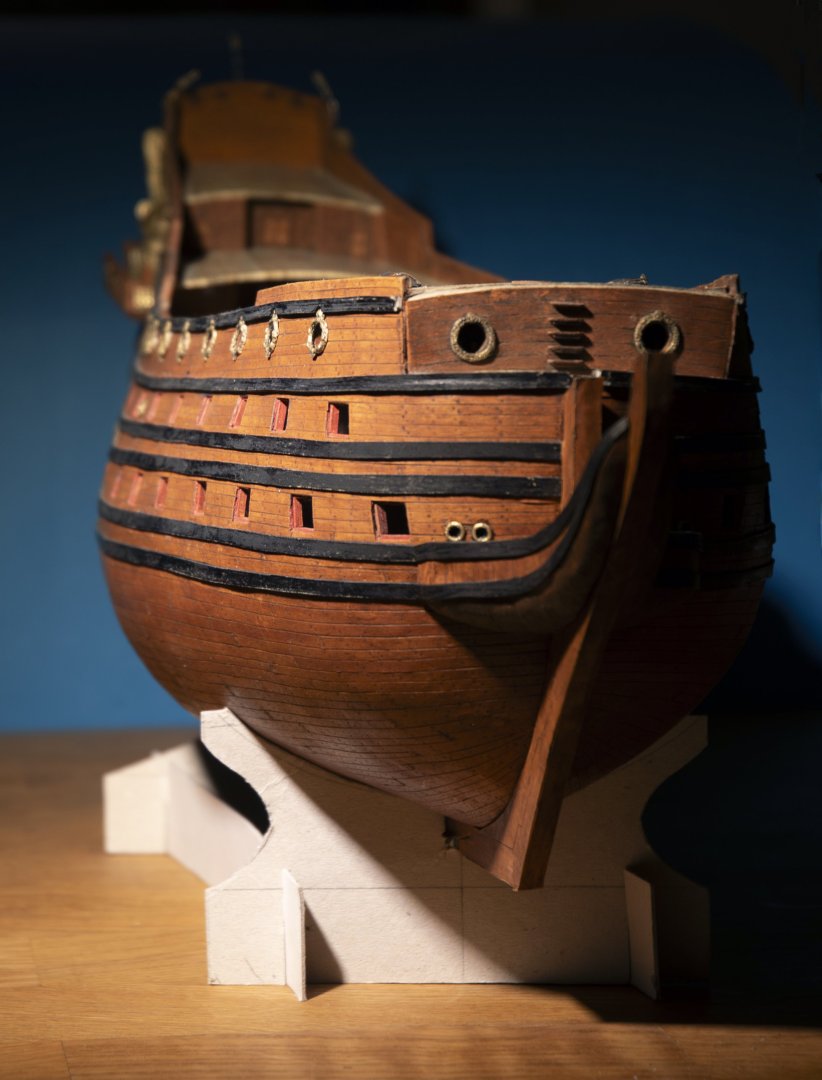
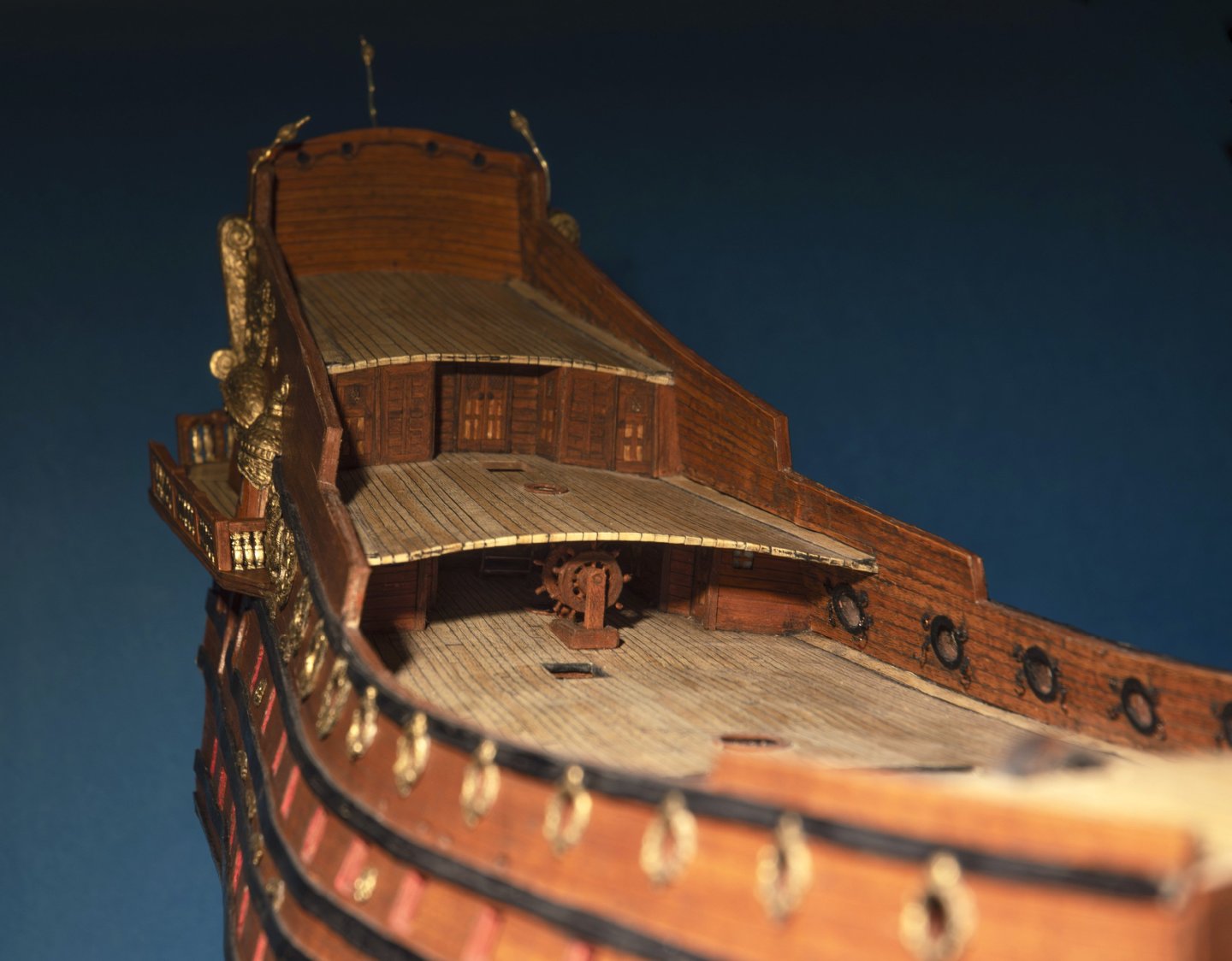
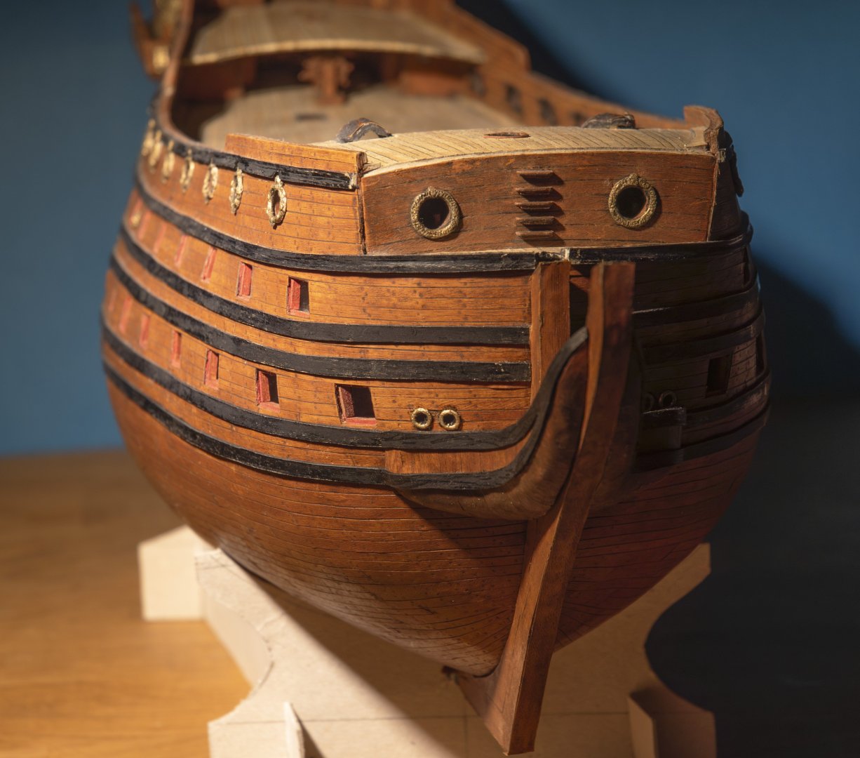
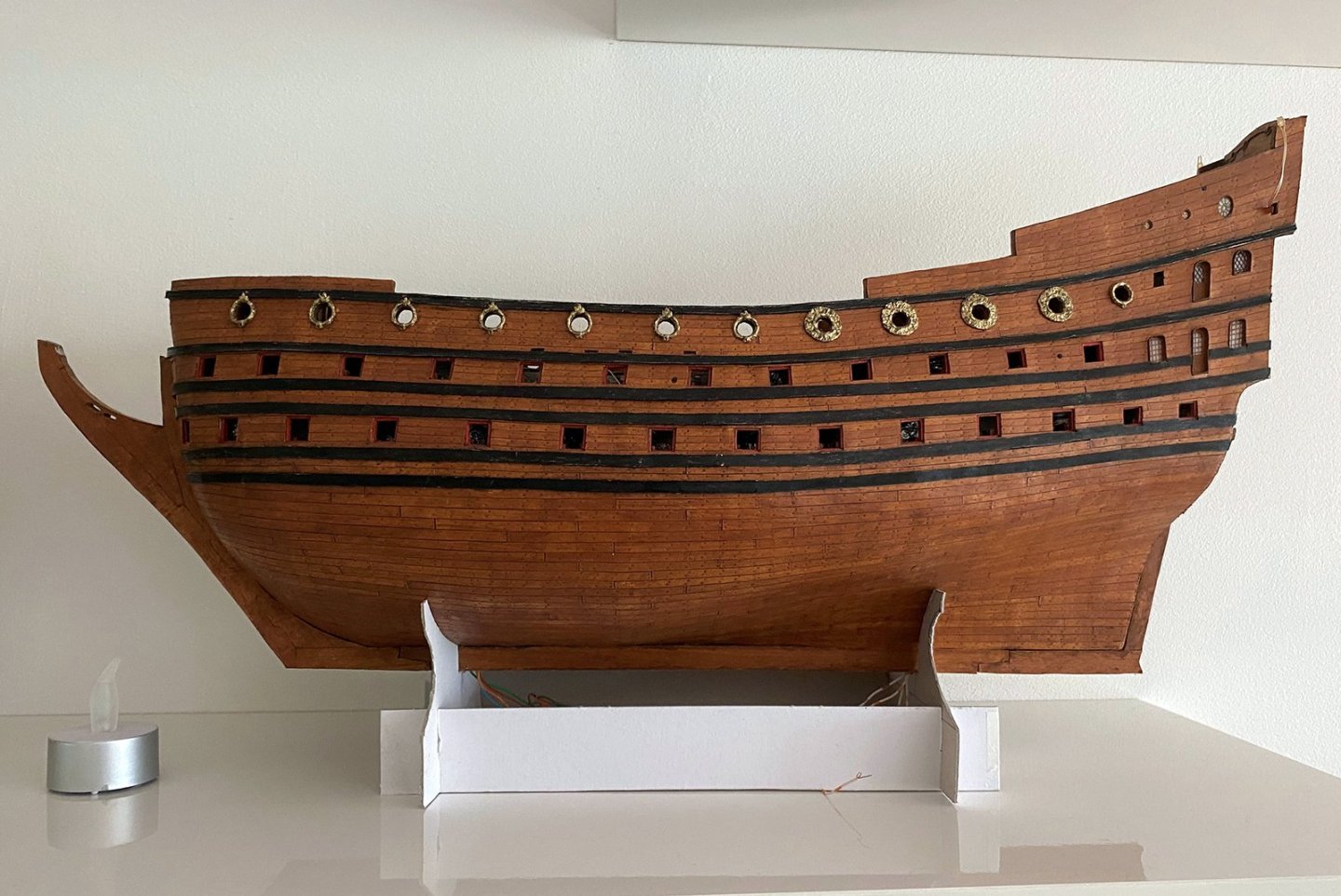
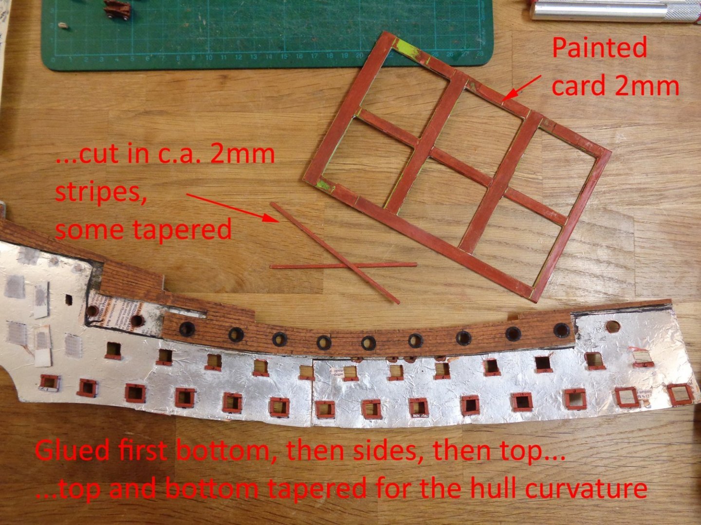
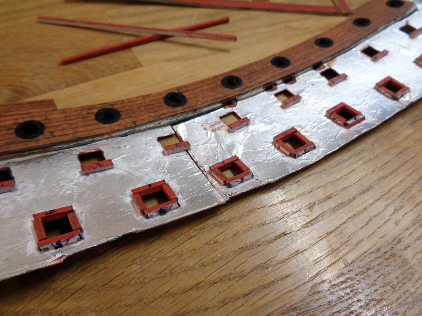
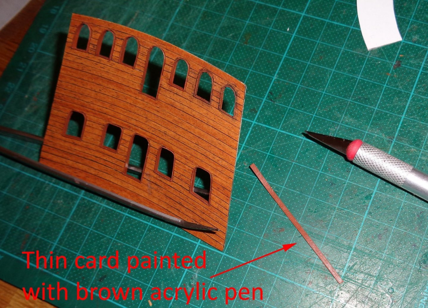
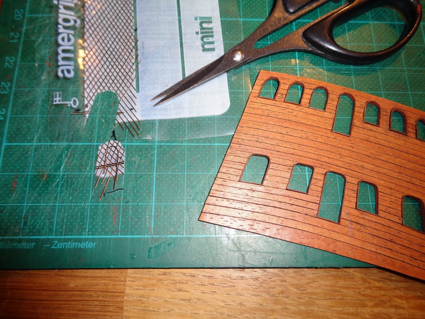
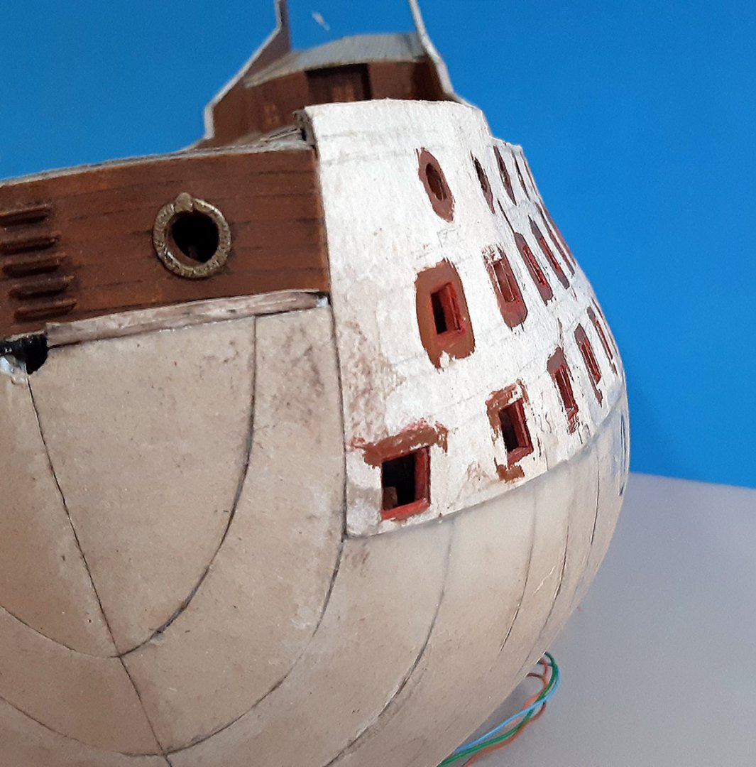
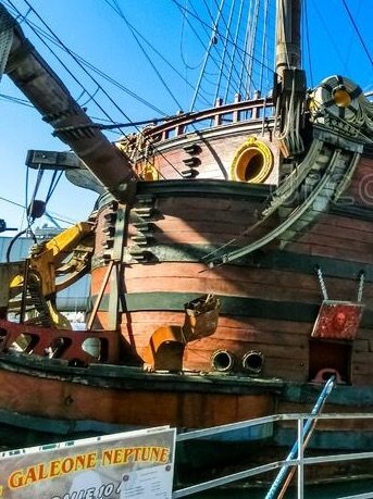
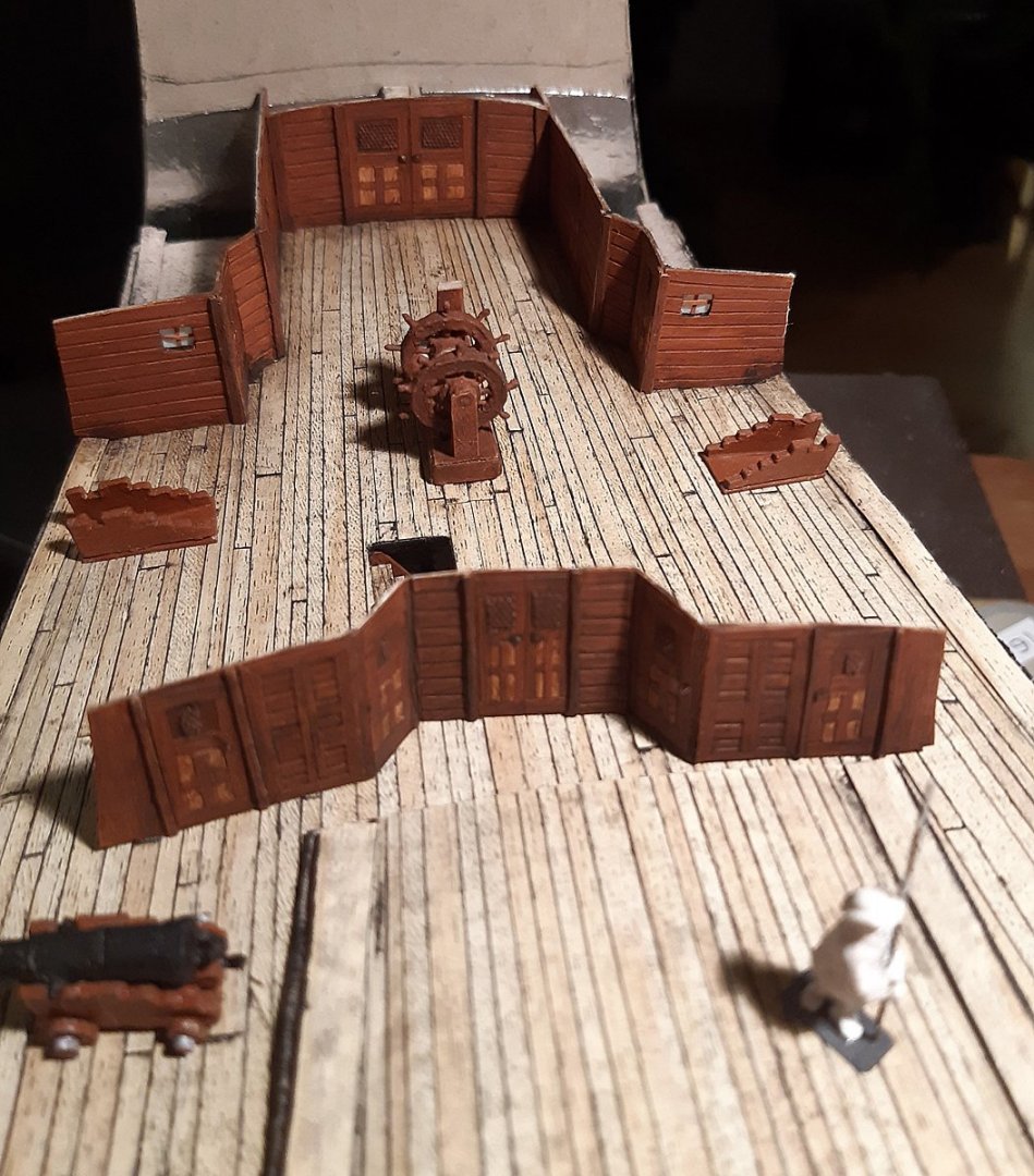
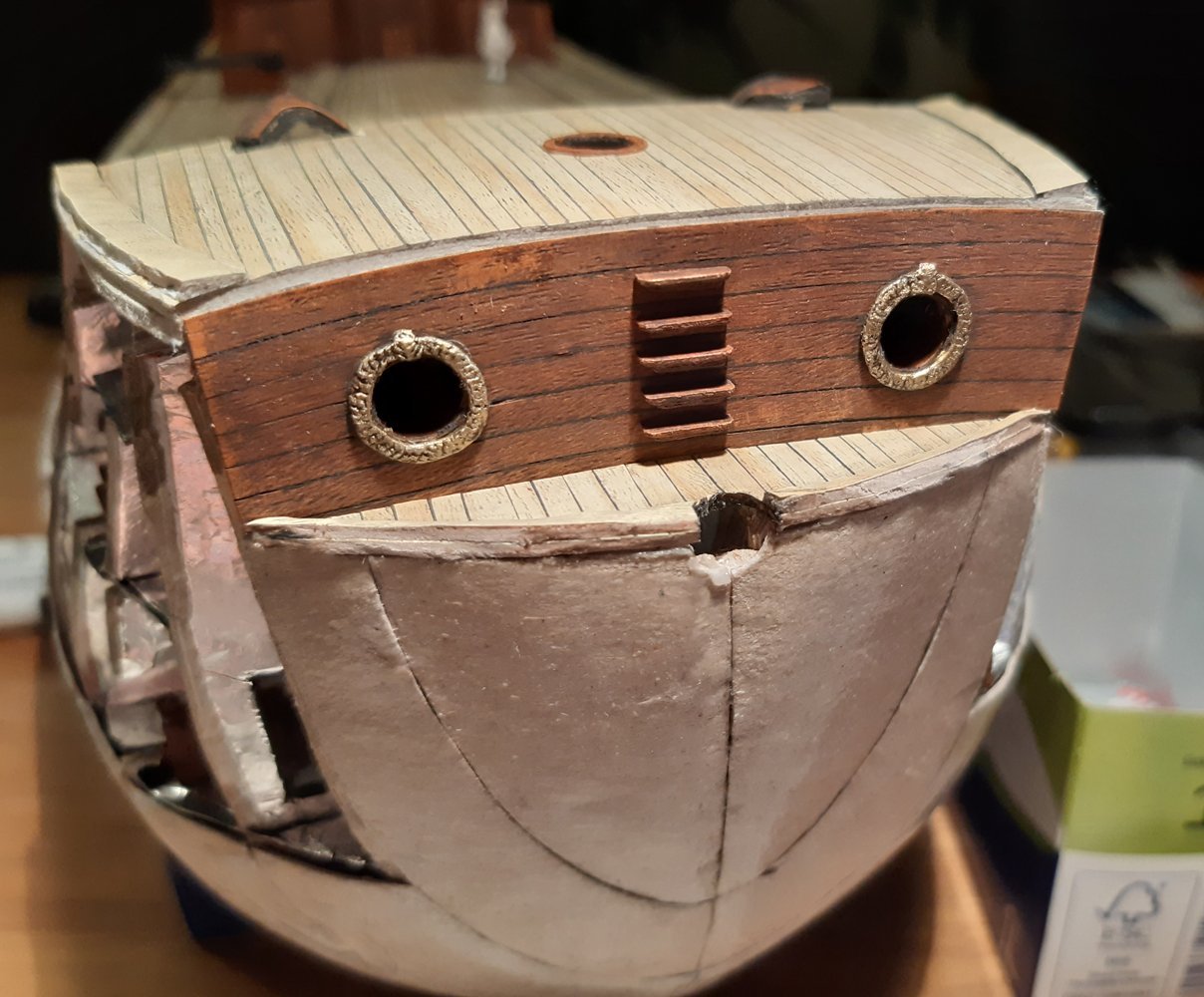
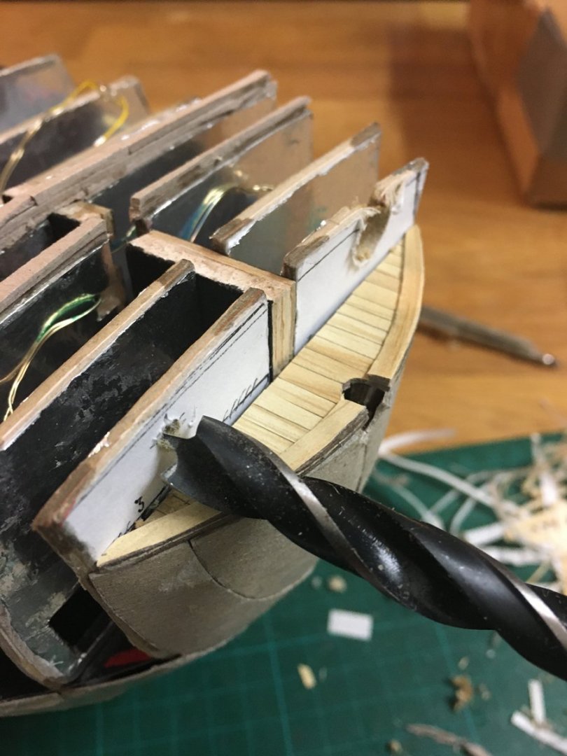
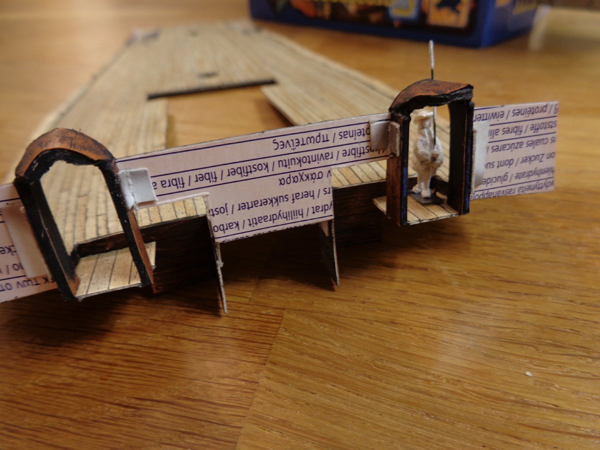
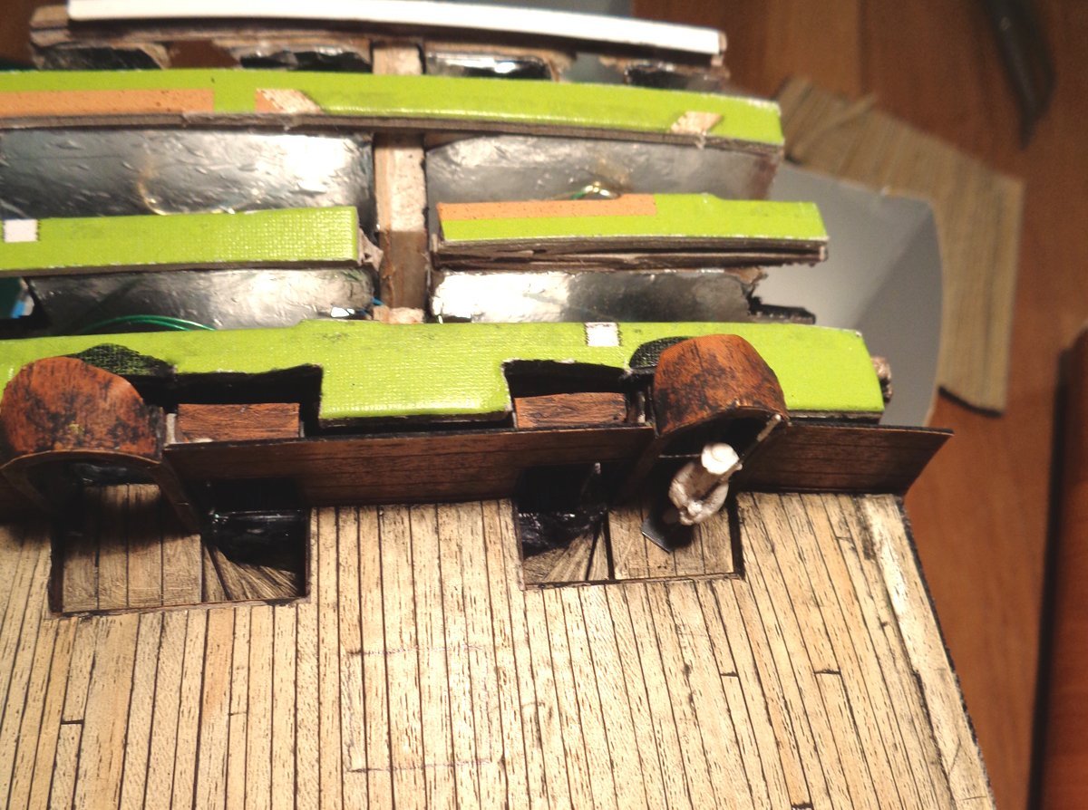
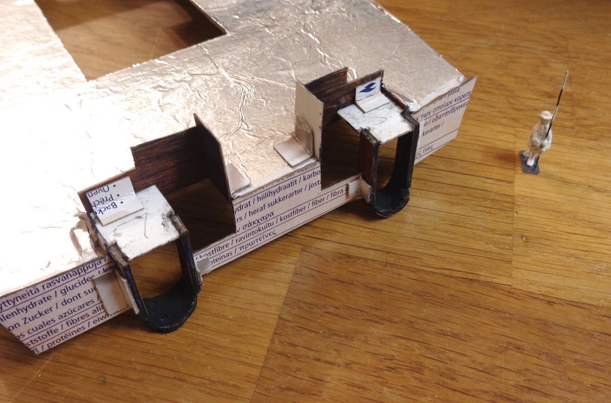
Hi there, Indeed, my keel length seems to fit well after all. The straight keel and the shallow underwater hull resembling rather a raft than a real ship is the product of a steel hull underneath all the wood. One can see the steel frame in the following picture of the head of the galleon, especially the knee of the head. On the internet there are also some pictures of the interior, where one can see the red steel hull. So there will be a lot for me to change with this knee and the whole head construction including the keel, gammoning knee, etc... But back to the build... Here are some pictures about the walls on the deck and how I made them, using the self adhesive foil and some oil paint for alteration. I cut stripes to imitate the planking and attached them on the walls, which in turn were also prepared with the self adhesive foil. For the window grating I used the inside of a wound plaster, or band-aid. Then it was all altered with black oil paint and I think I also used a bit of brown "burned sienna" and "burned umber", at least to imitate the door handles. I also made a tryout with the clay and baked two ornaments for the chaser gun ports in the fore castle. But as I was preparing the frame I forgot to make the holes for them in the bulkhead... And realized my mistake after I glued the frame together...Had to drill it gently with a drill for wood by hand, so as to not shred the whole frame into paper-maché... The entrance to the fore castle had to be changed from the original. The real Neptune has an entrance that goes a few steps down and the fore castle is only about a meter higher than the main deck. However, the gun ports in the fore castle are at the same height as the ones from the main deck. This makes no sense so I had to raise the fore castle a bit and still stay somewhat truthful to the shape of the ship, introducing only one step down to the fore castle. Next to the entrance to the fore castle are also stairs leading down to the gun deck. The green stripes in the last image are additional "extensions" of the bulk heads to make the fore castle higher... When I decided to include the LED lights, I had to use aluminium foil on the inside, because the LEDs were not as bright as I hoped for. Later it turned out that I had to glue some aluminium foil also to the bottom of the gun decks, which was quite difficult because I had already glued all bulkheads in place...It turned out, after consulting a friend, that all was so dark because I did not use enough voltage. But I will explain my LED plan in the next post. And this is the current state of the model, I have attached one side to the hull and am currently working on the other one and the stern windows. My apologies for the bad quality of the photos, there is currently not much daylight here in Finland... So much for now. I will post soon again about the LEDs. Rgds, Radek


-
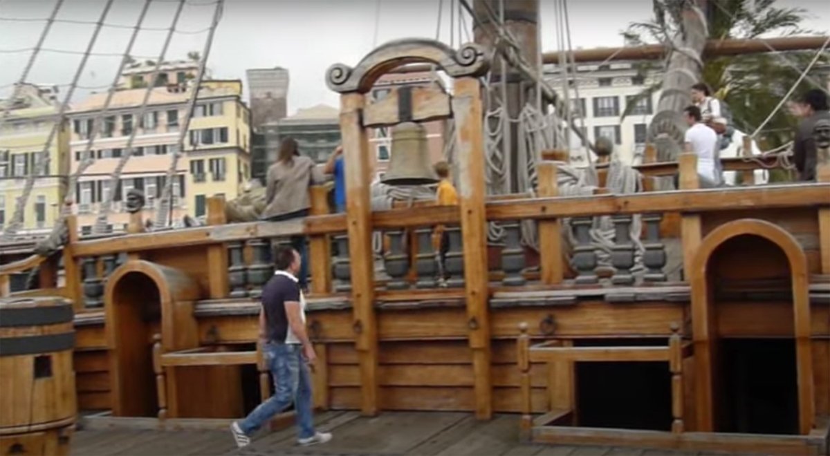
Ahoj Mirku! Sorry but my czech is terrible! So I will answer in english: I have the movie. It is not easy to find, but sometimes amazon has some copies to sell. I think there is also a free copy somewhere on youtube? Although this is a pirate ship thread and we talk about a pirate movie, I do not encourage pirate copies! There is plenty of photographs of the NEPTUNE in the internet and even some nice videos of the replica on youtube, if you wish to do your own model. It would be nice to see others doing it a s well. If you want, pm me an I can send you scans of my "plans" as a starting point for the hull. Nice that you could see the replica in real life! Unfortunately when I was there we did only pass through Genova. Currently the build is on hold until autumn, as I like to enjoy summer mostly outdoors. The current state of my model is that the side of the hull with inner planking is almost finished. However, the lighting I installed seems a bit dark so I'd like to see if I can change the potentiometer settings to make it brighter (not so easy to see during summer here in Finland when the nights are almost as bright as the day ). Please be patient with me. I willl continue with the NEPTUNE soon! All the best and stay save! -Radek
-
Papegojan 1627 by mati - FINISHED - 1/48
RdK replied to mati's topic in - Build logs for subjects built 1501 - 1750
Hi, No może byda poczebowoć pomoc bo jo żych jest ze ślaska... ”yes maybe I need help because I am from silesia...” Thank you for the info!I will look it up! Rgds, Radek -
Papegojan 1627 by mati - FINISHED - 1/48
RdK replied to mati's topic in - Build logs for subjects built 1501 - 1750
Hi Matt, Which shop from are you buying the polyester threads? Next time I'm in Poland I'll by some for myself. Your ropes look so fantastic, I'm inspired to build a proper rope walk. (I have only some laughable hand-twisted rope-walk, because I don't wanted to spend any money on making one...) Also the whole build looks very professional. Thanks for sharing! Rgds, Radek -
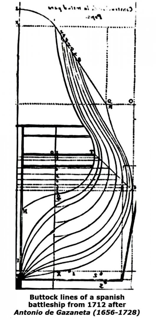
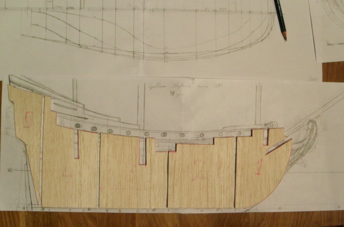
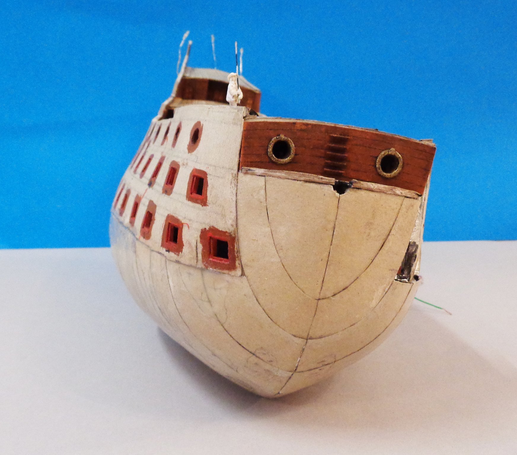
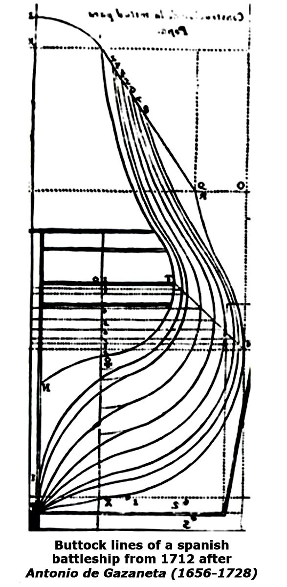
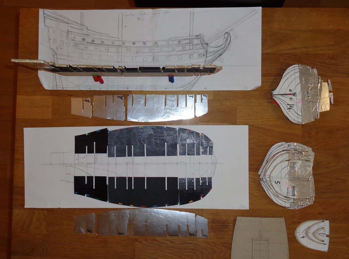
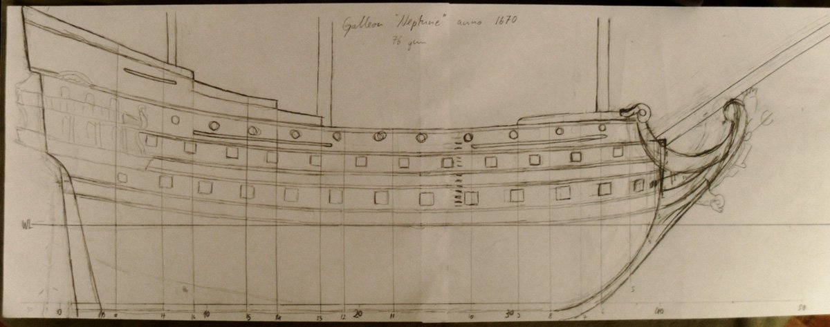
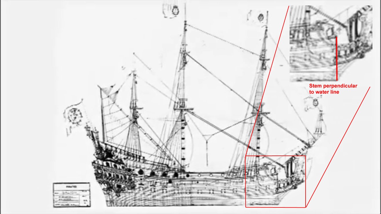
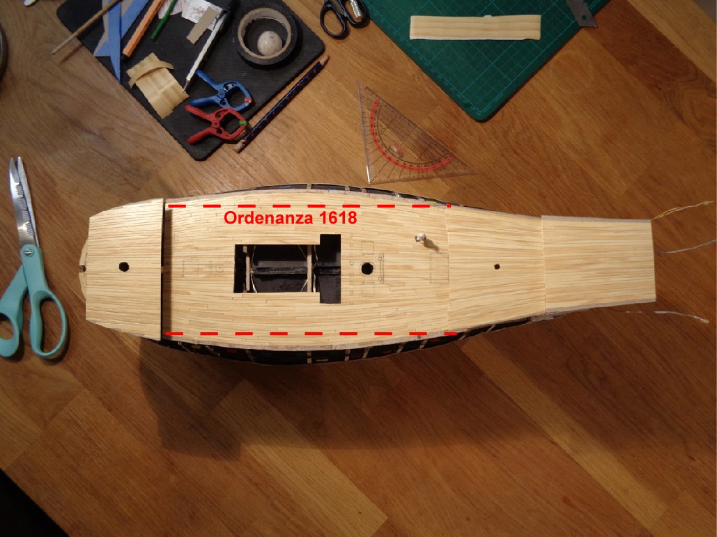
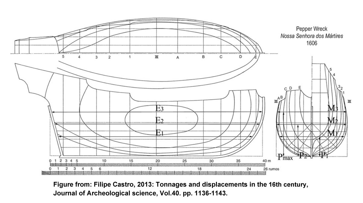
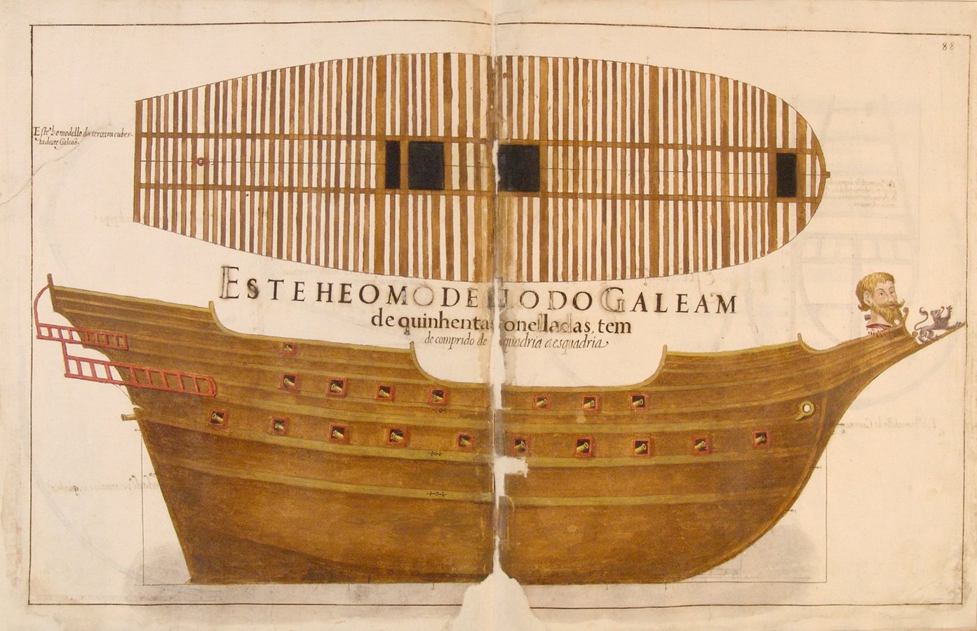
Hi and thanks. But to be honest, my lines are not that good. The model I make is too short for this lines. I borrowed them from Gaztañeta from a ship from 1712, which was already the new period of the eighteen century navíos, or ships, as published by Gaztañeta in 1713 and 1720: Medidas arregladas a la construcción de un bajel de guerra de sesenta codos de quilla, in a memorial of Bernardo Tinajero (1713) to the King: De lo que se ha de observar, y regla con que se ha de hacer la fábrica de diez bajeles y dos pataches que S.M. ha resuelto se construyan en el puerto de La Habana. Proporciones de las medidas más esenciales para la fábrica de navíos y fragatas de guerra, que puedan montar desde 80 cañones hasta 100, con la explicación de la construcción de la barenga maestra, plano y perfil particular de un navío de 70 cañones, con los largos, gruesos y anchos de los materiales, escrito de orden del Rey, Madrid, en el año de 1720. This was the end of the treasure galleon era of the Spanish armada, of which the Concepcion was the last galleon build based on the Ordenanzas from 1666 and 1667 (modified from the Ordenanzas from 1608, 1613 and 1617). Please correct me here if I am wrong with my research... I modified these lines a bit according to the photographs of the Neptune and tried to stick to the about 60m total length of the replica. My plans got it a little bit shorter, having a keel length of about 32 meters, instead of the 40m of the replica. But then again, on the other hand... I am not sure, but the keel of the Neptune replica goes all the way to where the stem begins, as it in turn goes in a straight line perpendicular to the water line down, resulting in the 40 meters. Just recently I found a picture of a plan of the replica in a youtube video about the 'making of' the movie (I wish I had found it back in 2012), sorry for the bad quality... (Original plans of the prop for the film - note the very shallow underwater hull! It has a draft of only 2.2 meters according to Wikipedia) (My plans from 2012) ...So because of being too short for these lines, the shape of the ship is not as elongated as it should, but rather round like an egg. The Spanish ships in the 17th century were often build slim (one might think about the race galleons of the 16/17th century), with a length/beam ratio of about 3, give or take. And before the Ordenanza 1608 even close to 4. In comparison, the Neptune has a ratio of 2.6! I found measurements for a galleon build after the Ordenanzas from 1618, close to the dimensions of the Neptune, with a deck length of almost 42 meters, a clean keel length of 30 meters, but a width of only almost 13 meters compared to the 16 meters of the Neptune. This converts to about 1.5cm wider on each side of the model. The calculated tonneladas are also similar, with the original one at 1186 tonneladas compared to the calculated 1312 of the Neptune (based on the formula I found in the research). However, the Spanish were not exactly famous for their mathematical skills and some researchers point that out in their publications, when comparing the capacities of the ships in tonnes and tonneladas. Again, the form of the ships back then was thus more straight compared to my model, which resembles more the form of a smaller vessel, such as the Portuguese-built pepper-wreck Nossa Senhora dos Mártires, which sunk 1606 near Lissabon. Interestingly it is not really smaller, but remarkably almost of equal dimensions (except it is not that wide)... (Figure taken from the depths of internet depicting a 500 tonne galleon by Manuel Fernandez.) So because of the Neptune being just a prop for a movie, I have to compromise a bit on historical facts. This is also true for the wheel, especially the 2 separate wheels, which did not appear before 1740! ...But it is a part of the replica so I included it. No one knows really when the wheel was invented to replace the staff, and some also debate if it was invented by the British Royal Navy or rather by some 'common dock hands and artisans'. As you correctly mention, the wheel appeared around 1700s and shortly after. However, if it was around in 1700s, it might have been in use already many years before and it just needed some time to become accepted. 1670 might be a bit far off from 1700s, but there's no limit to imagination... So much for now. Rgds, Radek
-
Hi! Wow! I am speechless. Such a great work on restoring this model! The lower hull looks amazingly well done! And the stain will surely go away smoothly. If not, CA is soluble in acetone (and alcohol to some degree) but I don't know if that would stain the wood even more. Maybe modellers with experience can tell better? I work only with card an paper (and balsa wood now and then), but mainly with rocks...(geologist ). I particularly like the difference in appearance between the lower hull and the upper parts. The underwater hull is nicely smooth compared to the planks above the waterline. But I like the look of it! Give it that authenticity of a very old (40 years was it?) model! Quite antique looking. I am sure the original stained sails would fit nicely! Rgds, Radek
- 740 replies
-
- 1
-
-
- Tudor
- restoration
- (and 4 more)
-
Hi Stephen, Yes, that's what I meant. After you sanded down the hull I can see from some of the photos you posted that it came out really smooth and beautiful! Rgds, Radek
- 740 replies
-
- 2
-
-
- Tudor
- restoration
- (and 4 more)
-
I wonder what is easier, sculpturing it from model clay or carving it out of wood? I plan to use sculpturing model clay for my Neptune build, but am ver afraid to produce "monsters"... Looking forward to seeing your next attempt! And if you could also let us know how you did it? Rgds, Radek
- 332 replies
-
- 2
-

-
-
- fluit
- abel tasman
- (and 1 more)
-
Hi! I was following along silently but now I have to say it: This is an amazing undertaking! Somewhat...masochistic...And I thought scale 1:100 is already enough "pain in the neck". You do a great job here. I am truly amazed! For my Mayflower I also needed 2mm triangle deadeyes, but I went a short cut and bought 3mm round ones and filed them into shape... I also like what you did to the underwater hull. Great work! Can you share more pictures? Rgds, Radek
- 740 replies
-
- 5
-
-
- Tudor
- restoration
- (and 4 more)
-
Roter Löwe 1597 by Ondras71
RdK replied to Ondras71's topic in - Build logs for subjects built 1501 - 1750
Hi! Great work on the railing! How wide are the rails on the main deck in real? That is something I can never really figure out? Rgds, Radek -
Berlin 1674 by Strelok - 1:100
RdK replied to DaKea90's topic in - Build logs for subjects built 1501 - 1750
Hi, Very interesting preparation and research. Since it was a dutch-built ship, did you consider to check the beam width to keel ratios of dutch vessels of that time and compare them to the different plans you have? I would be glad to see you building that model from card and paper! Scale 1:100 is surely not easy from wood. I have never really build a ship from wood except my Elbing Cog (balsa wood, if that counts) but I can imagine that the wood starts to splice easily when making parts that small and tiny? Looking forward to seeing your progress! Rgds, Radek -
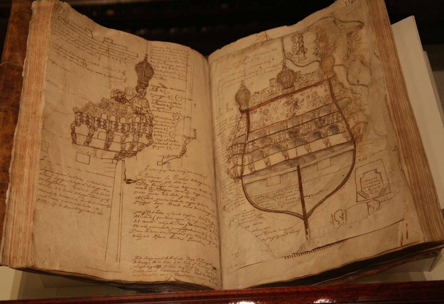
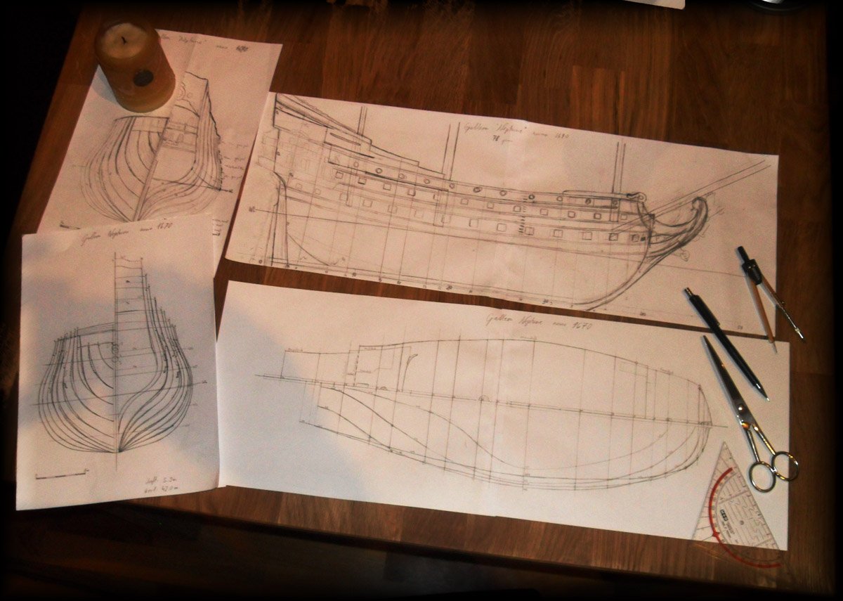
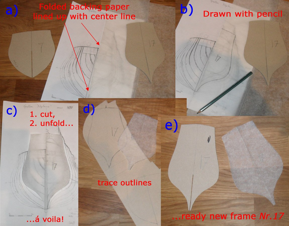
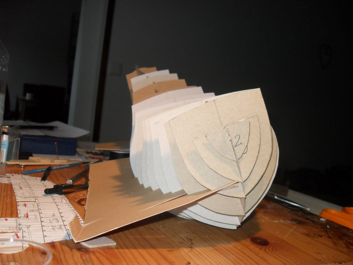
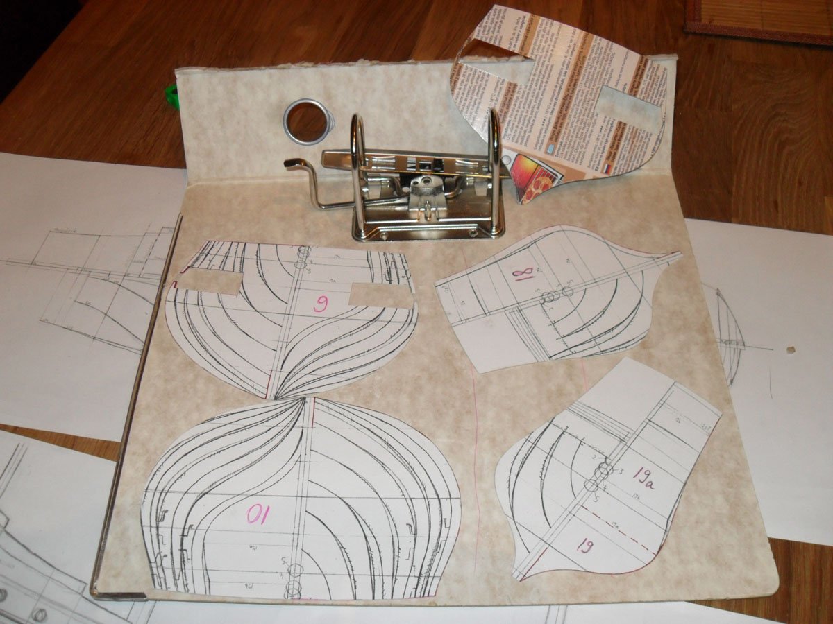
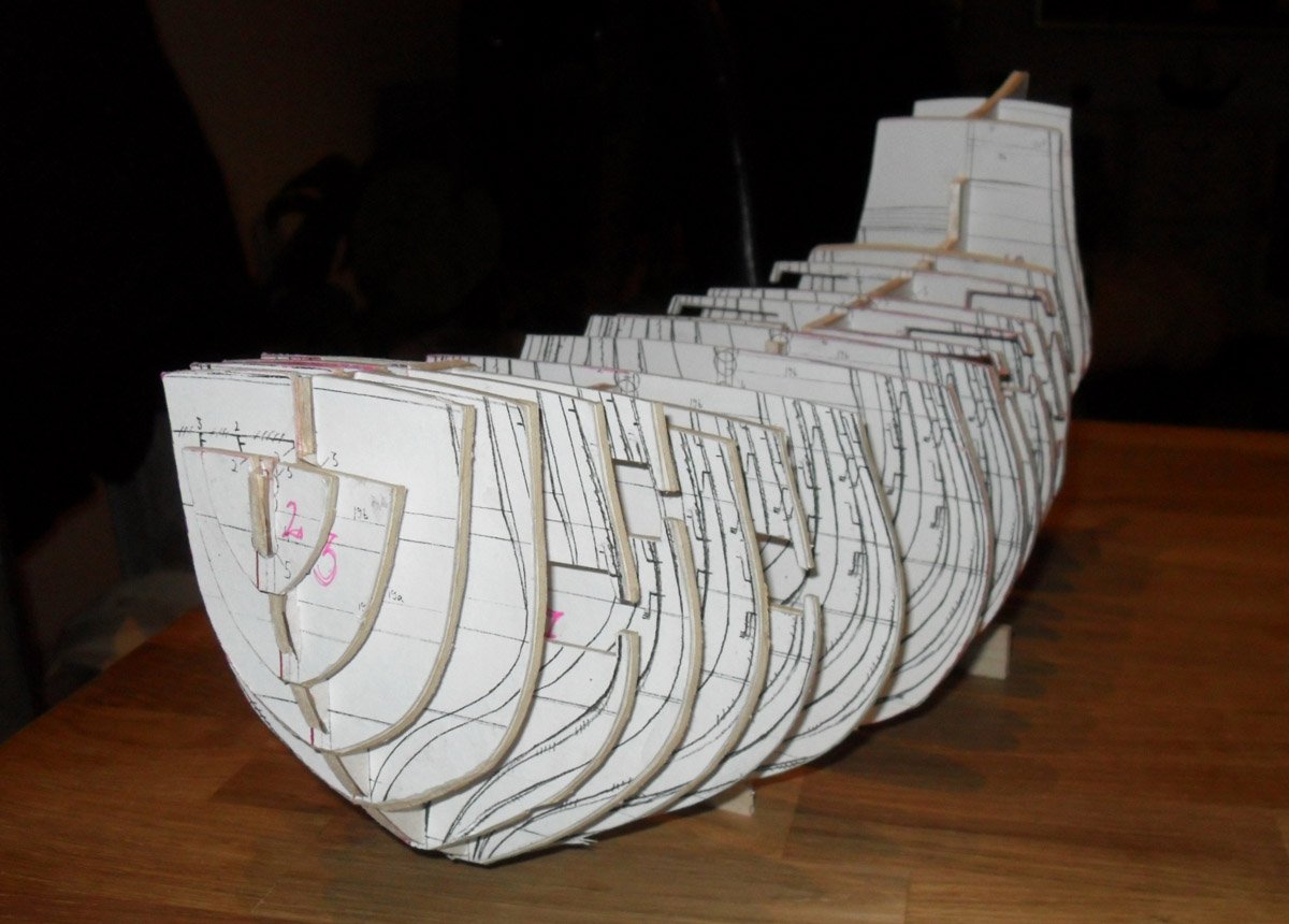
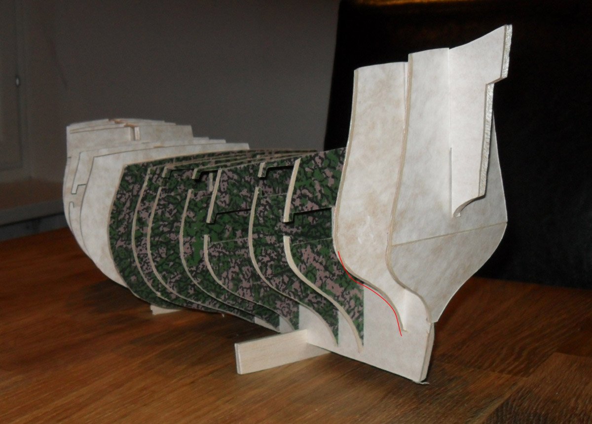
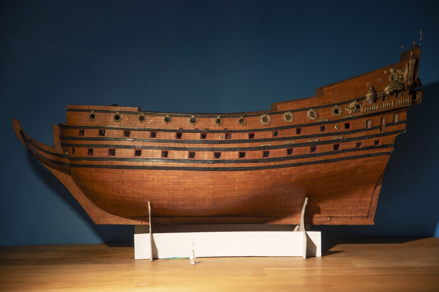
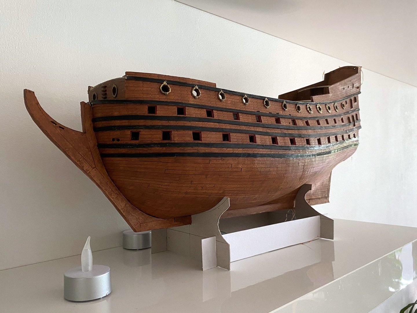
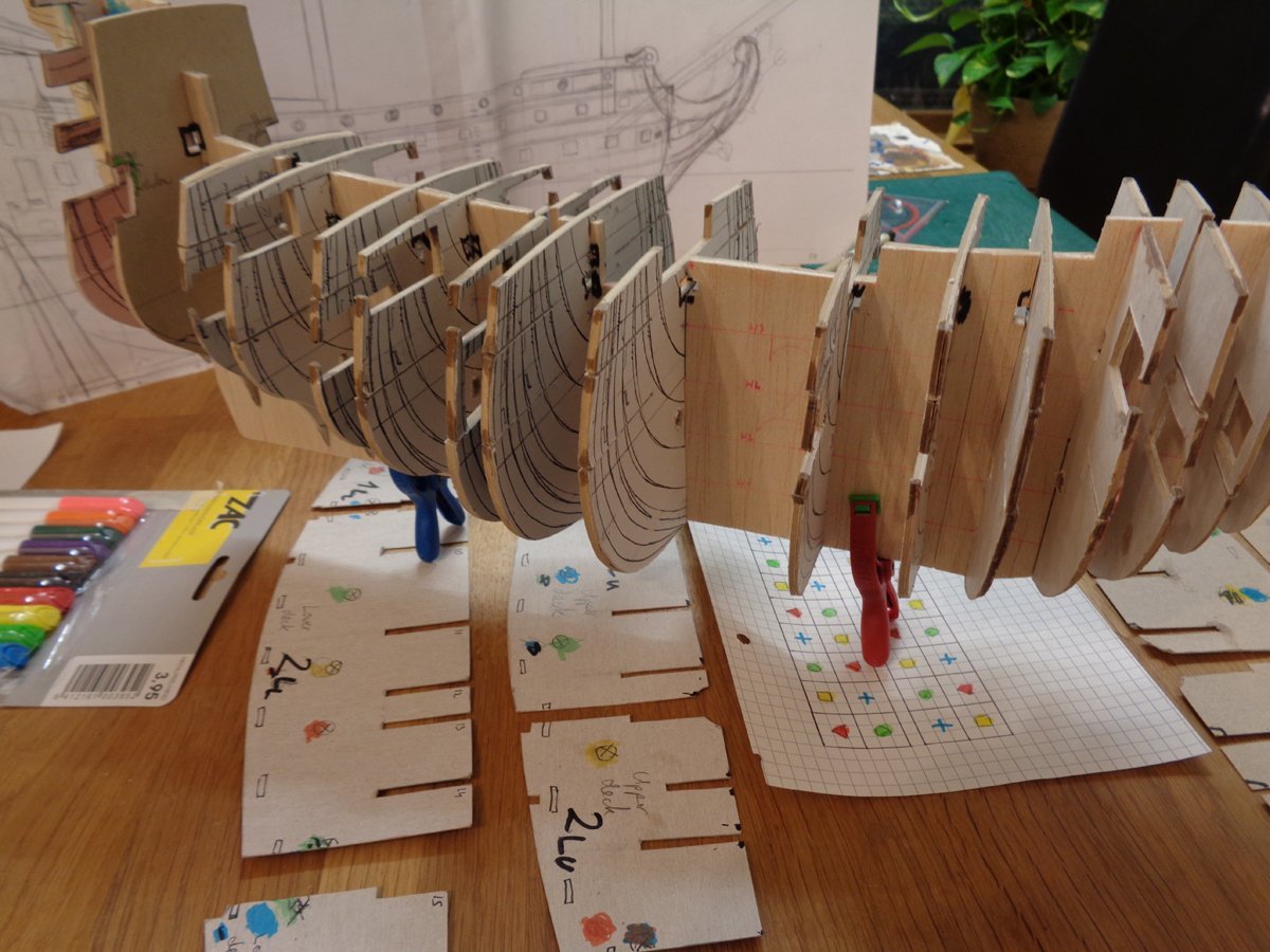
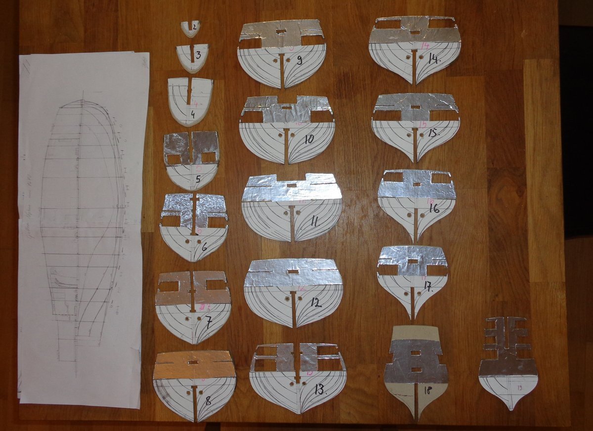
Hi, Thanks for your interest in this build and the likes. The Neptune was apparently a "well researched" replica of a Spanish treasure galleon from that time, but it obviously is just a fictive imagination, although a very beautiful one, of a real ship from that era. Of course the ship was build wide enough for the camera team to operate smoothly on the decks, but I will get to the width of this ship in a later post... Back in 2012, looking at all the photographs I could find on the internet, I decided the ship must be the size of an HMS Prince. Having no plans, water line drawings or buttock lines, I decided to borrow some from the famous Vice-Admiral and shipwright José Antonio de Gaztañeta. I also ordered some books about Spanish galleons and from the maritime museum in Madrid the plans for the "Nuestra Señora de la Concepción y de las Ánimas (1687)", also by Antonio de Gaztañeta. Gaztañeta's buttock lines were a bit younger, but they gave me a good starting point for my own ones, which, after tedious studying of photographs of the Neptune in wikipedia and other sources (mainly comparing ratios of lengths) led me to the following result: So from here I made a "preliminary pizza-box" frame to see if the lines were adding up nicely. Of course they did not and I had to fix the one or another bulkhead. This fixing continued even until the point when I started to cover the bulkheads with the side panels (also made from pizza box). After being satisfied with the pizza-box version I started to make the middle frame from balsa wood and a thick (2mm) layer of card and the bulkheads from a thick (3mm) card from some very old file folders that I found in the storage at my workplace. They wanted to throw them away so I collected as much as I could carry (in my IKEA-bags). The good thing about these old folders is that they are thick, but not laminated card. Ideal for heavy ship modelling! At this point I had to take a break from the build and got shortly back to it in 2018, when I saw the flickering candle light on Instagram. This motivated me to get back to this build but it took me still 2 more years, before I could really continue. So much for now. More on the development of the LEDs in the next post. Rgds, Radek