


jack.aubrey
-
Posts
1,268 -
Joined
-
Last visited
Content Type
Profiles
Forums
Gallery
Events
Posts posted by jack.aubrey
-
-
Posted: Sat Mar 01, 2008
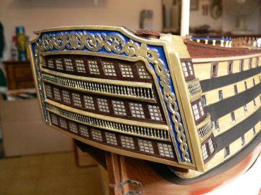
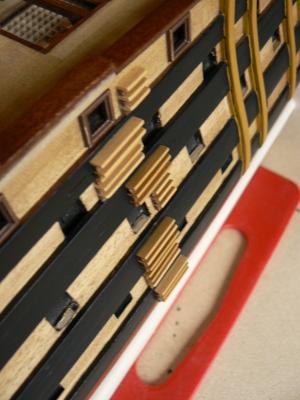
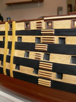
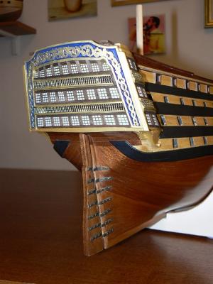
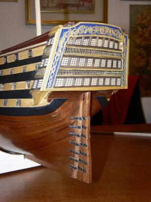
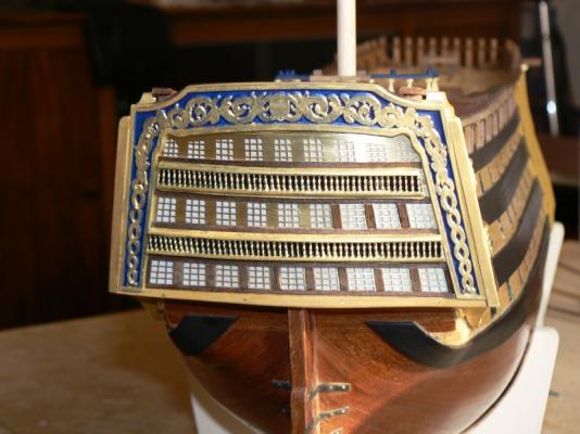
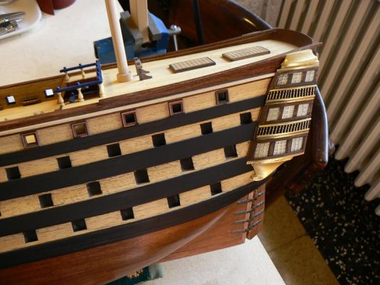
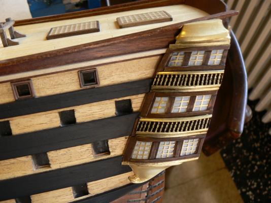
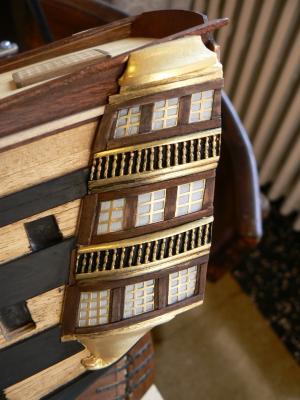
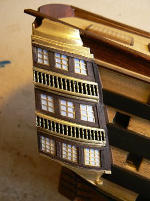
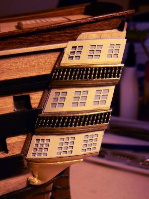
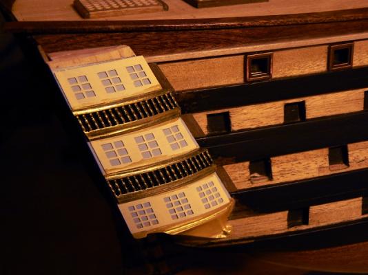
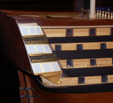
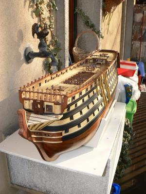
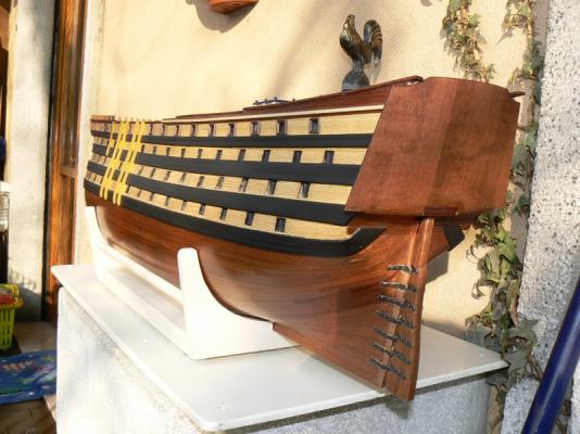
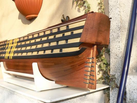
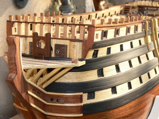
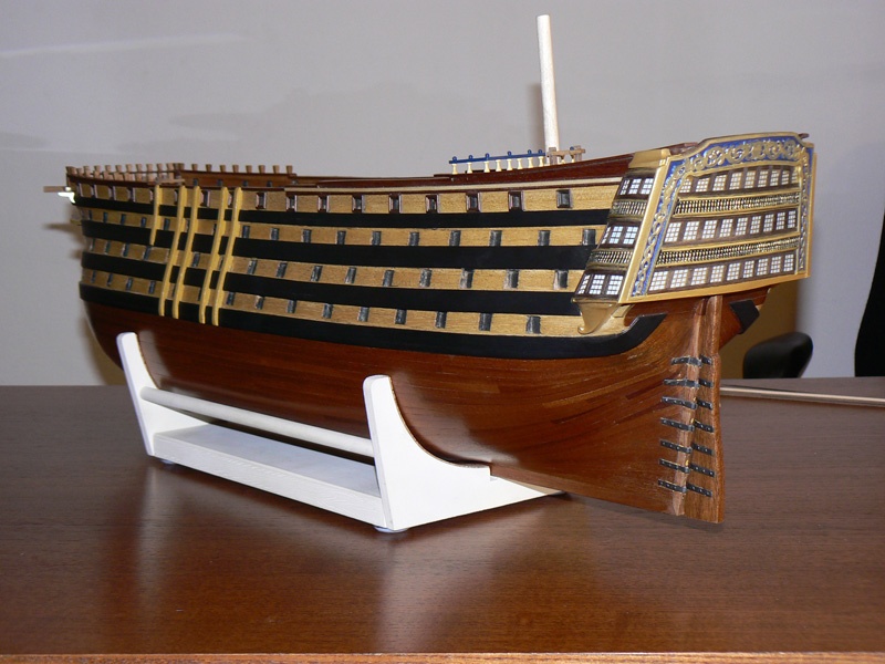
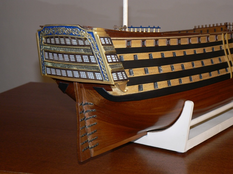
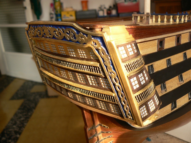
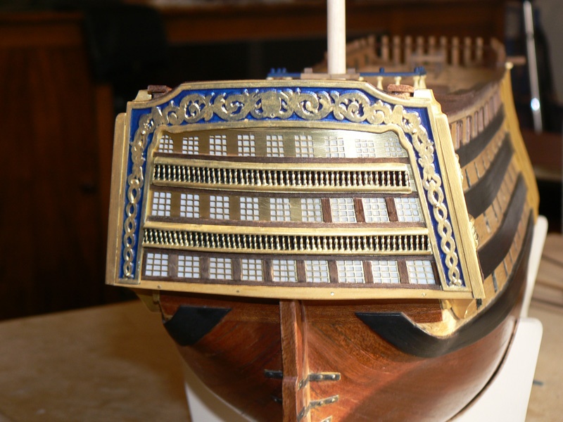
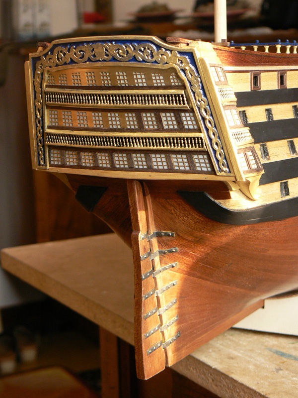
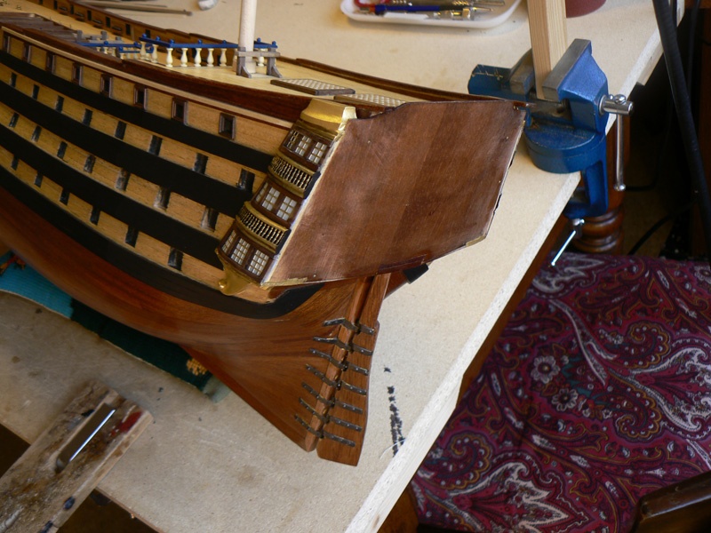
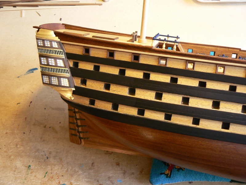
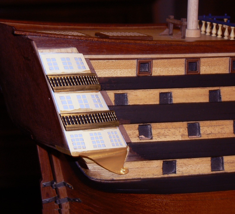
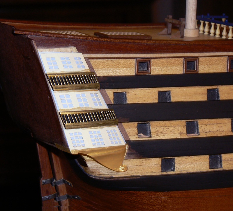
I don't have any new work to show you but I want to include two new images of the stern galleries, where I have now applied a coat of transparent paint, and to other images of the side ladders from a different perspective.
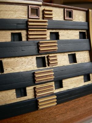
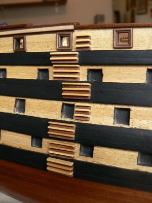
Regarding the side ladders I have to decide about the color.
Looking at some photos of the HMS Victory in Portsmouth, I have seen that these pieces are painted with yellow where the sides are yellow and in black on the wales.
I'm thinking that also on the spanish ships this rule should be the same, so I'm considering to leave unpainted the ladders over the clear wood and to paint with black where they lay over the wales.
Any suggestion ? Regards. Jack.Aubrey


- WackoWolf, cristikc and shipcarpenter
-
 3
3
-
Posted: Thu Feb 28, 2008
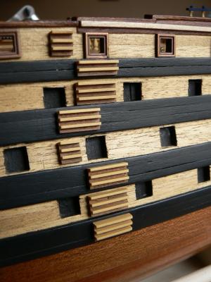
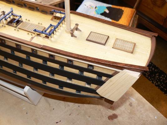
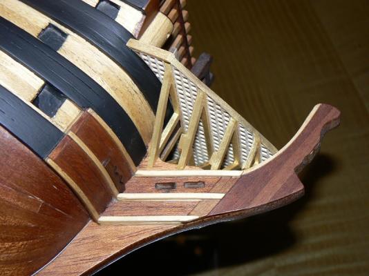
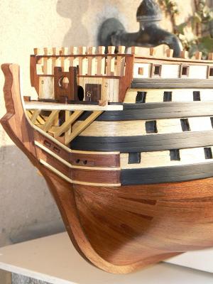
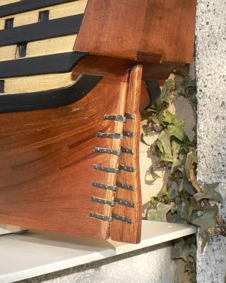
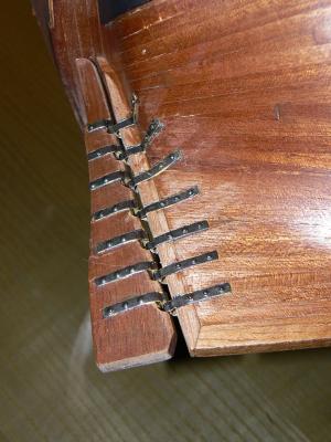
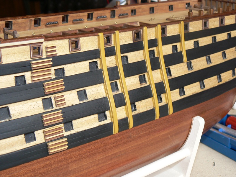
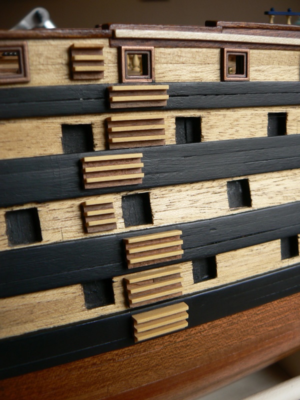
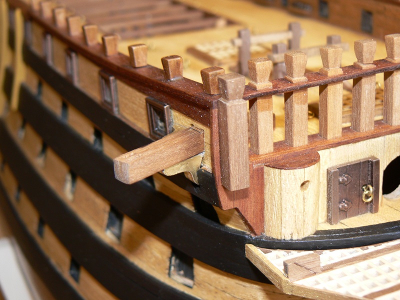
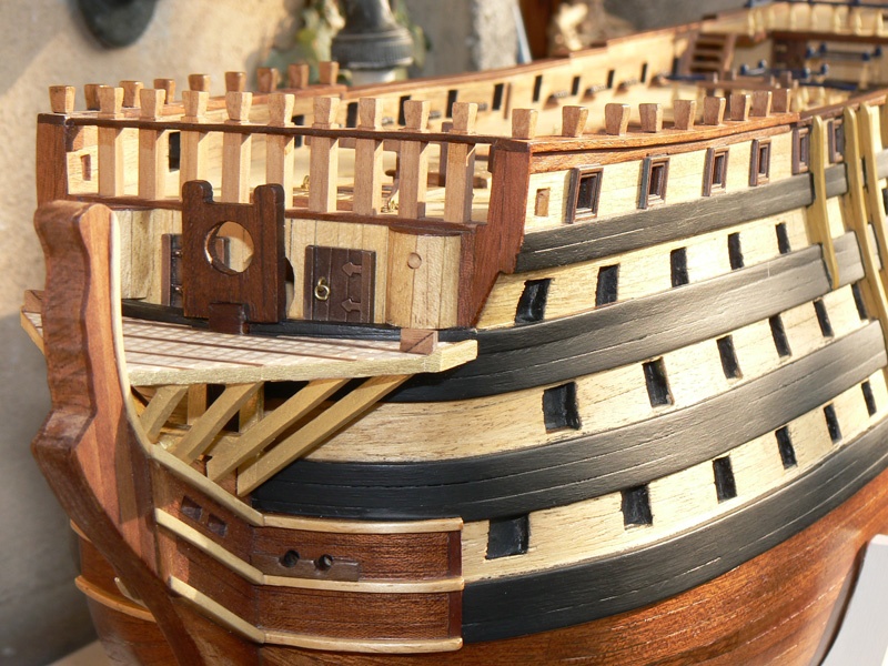
As I said in my last message there is plenty of tasks to do on the model: in spite of my previous list I decided to build the side steps.
Considering the huge size of the Santìsima Trinidad's gun decks also the side steps are quite impressive.
The kit manufacturer instructions were to use two kind of stripes to build the steps: a mm. 1x4 stripe and a 2x2 stripe, both in sapele wood. I decided instead to change the kind of wood: boxwood for the 1x4 and walnut for the 2x2. Especially the boxwood was for me a very good choice.
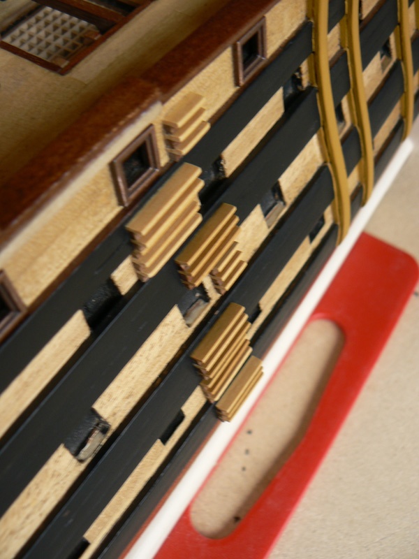
An important thing was the building process: I made a kind of sandwich made alternatively with a 2x2 stripe and 1x4 stripe glued together one over the other for six times.
The new stripes, approx 12 cm. length, were then cut in small pieces of two different lengths (18 o 8 mm) and refined with sandpaper.
The last task was to fix them on the hull sides with some points of glue, a final coat of matt transparent paint and . . . . the work is done ! Time elapsed two sessions of 1 hour and half.
The first two images show the starboard side steps and the remaining two the larboard. In the last image you can also see the skid beams, for raising barrels, etc. and to protect sides against boat being raised, close to the steps.
Kind regards. Jack.Aubrey
- WackoWolf and CaptainSteve
-
2
-
Thank you Yves,
I wish to you, to Fam and to all the other members of MSW, and to their family as well, a Happy Christmas and a Happy Prosperous 2015 . .
-
JA
I'm really impressed! All that thinking produced an outstanding result, like very much the choice of colors. And confirm you, with an "exterior and independent eye" that the caulking is SUPER!!
Even the trick of the paper strips is very smart, I suspect that I will copy it...


Thank you for sharing and a big CIAO from your fellow-builder in the "Company of the Brick"

Fam
Thank you FAM for your comment, in effect I like both the caulking than the wood color. But I have to find somewhat to hide the holes of the temporary nails remained in the wood and that the oil amplified its visibility . . Any idea from you ? Cheers, Jack.
-
Monday, December 22, 2014
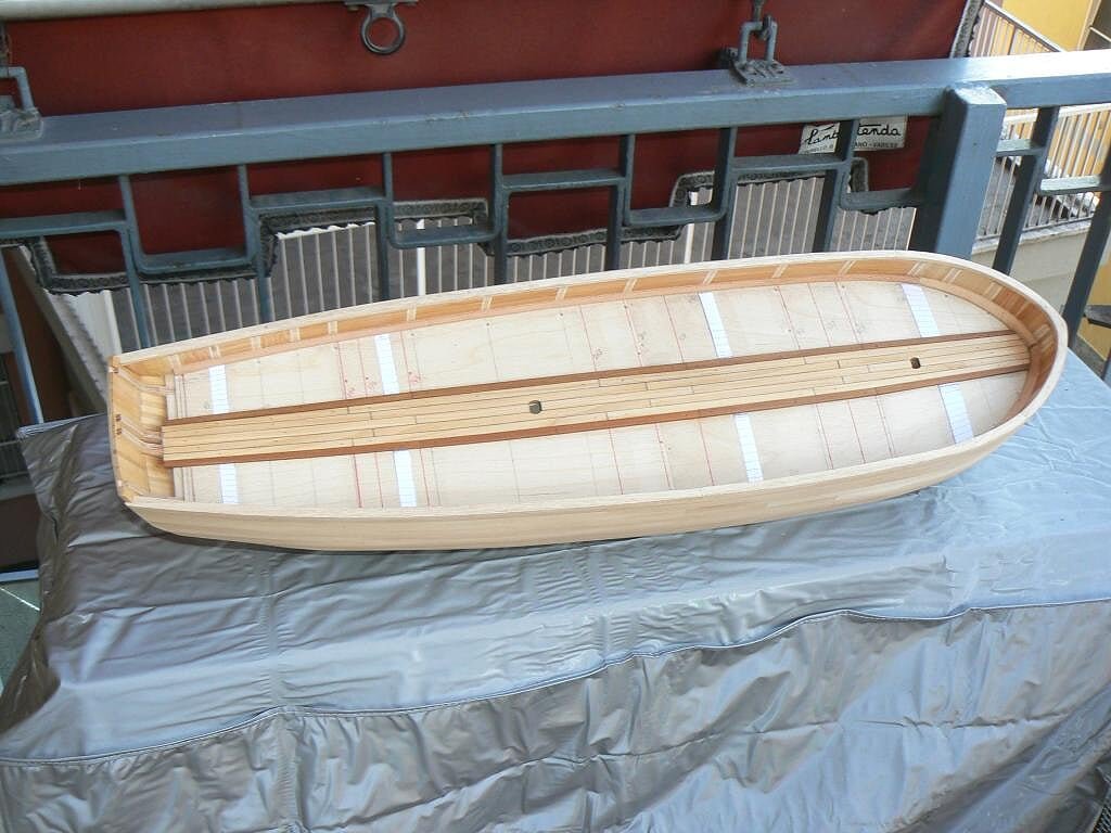
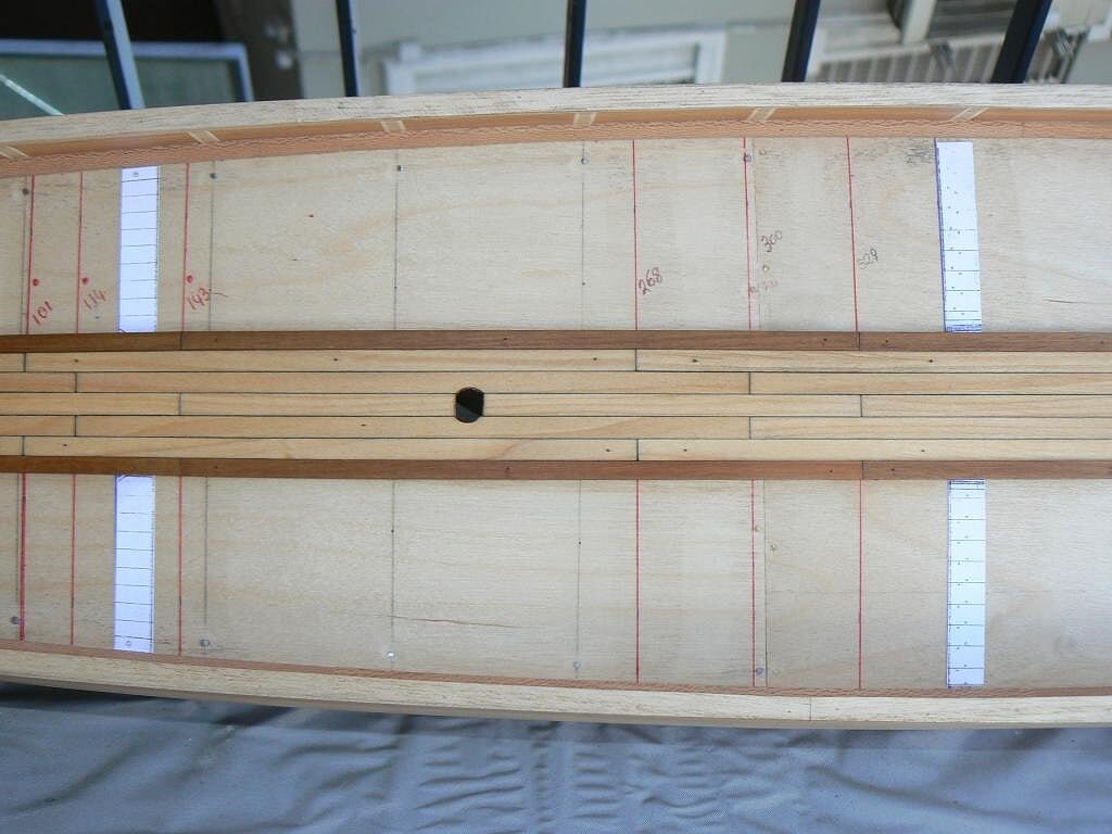
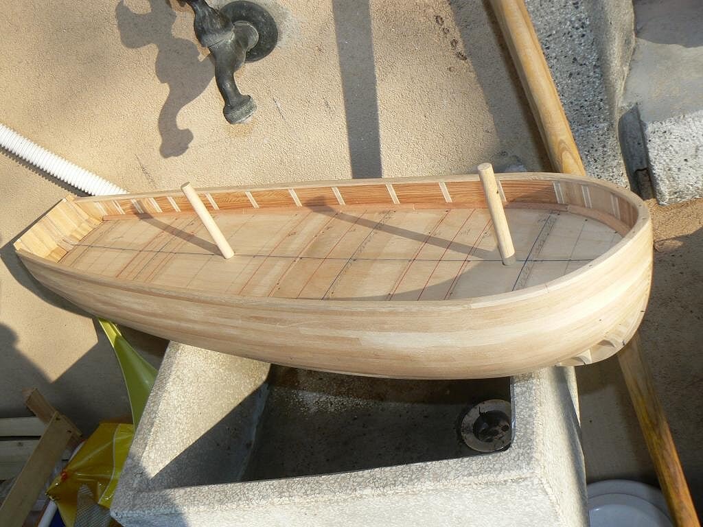
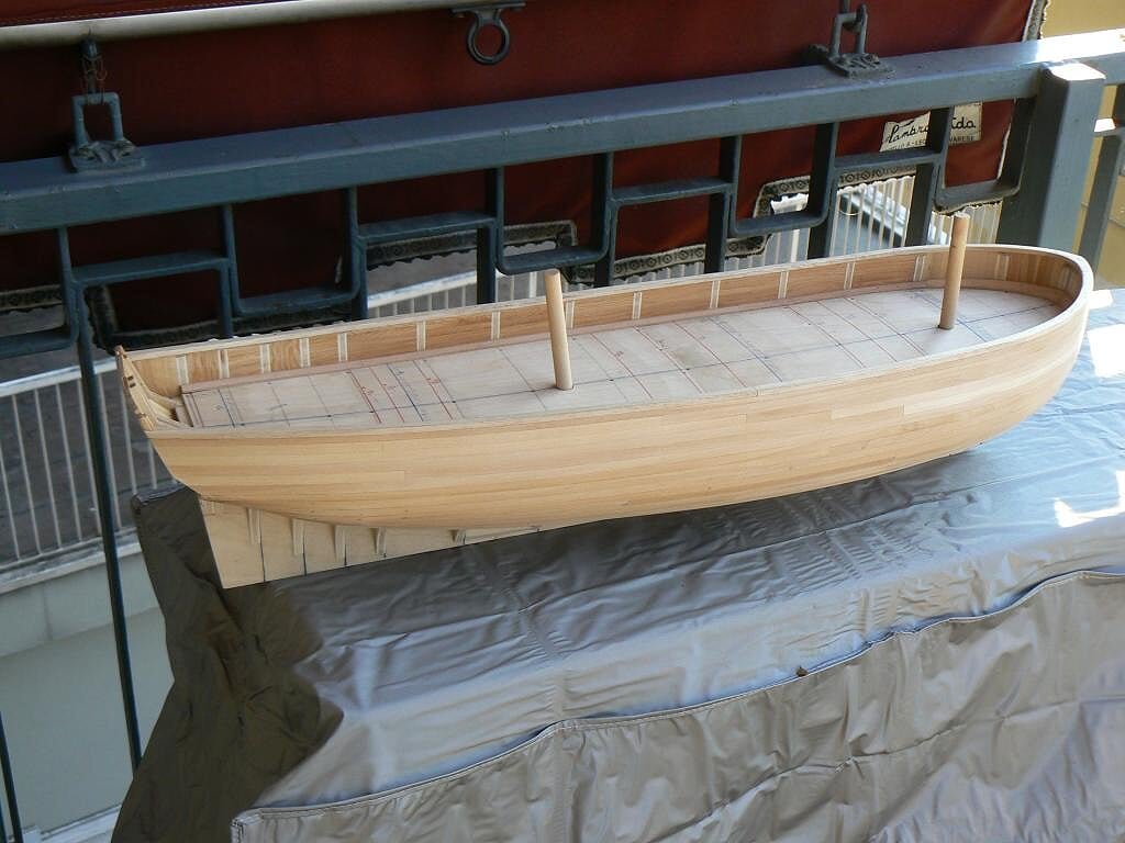
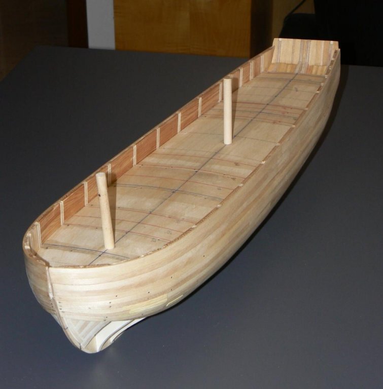
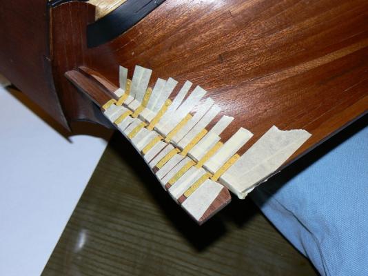
As promised, I finally started to implement the deck planking . .
Yesterday I spent part of the morning for the last preparatory activities: retrieve the necessary materials, prepare and glue into place the four strips of paper, taken by the deck plans, that will indicate the width of the strip at their position. I remind everyone that the strake hasn't the same width, but are tapered at both ends, this situation has never been experienced before by me.
Finally, in the morning, I glued the first strake, the middle one, to leave it enough time to dry out completely for the afternoon, when I started with the other strips. This first strake, unlike all the others, is not tapered.Then yesterday afternoon I started to work with other strips and I quickly learned the best way to use the Proxxon abrasive disk to taper them, so it has become a breeze. Each strake is divided into four sections that at full scale should correspond to planks of a length of around seven meters. The five central strakes are of limewood 2 x 6 while the two darker master plank are walnut 3 x 5.
For the simulation of the caulking I used the graphite method, this method, accordingly with tests previously made had proved good for the lime wood. Finally, when the glue has dried I proceeded to sand the job done and to apply a couple of coats of wood oil, which has enhanced the color immediately. . I'm "super happy" with how things are developing.
An overview. .
01 Brick%20by%20JackAubrey/P1100157_zpsfae5ce7c.jpg
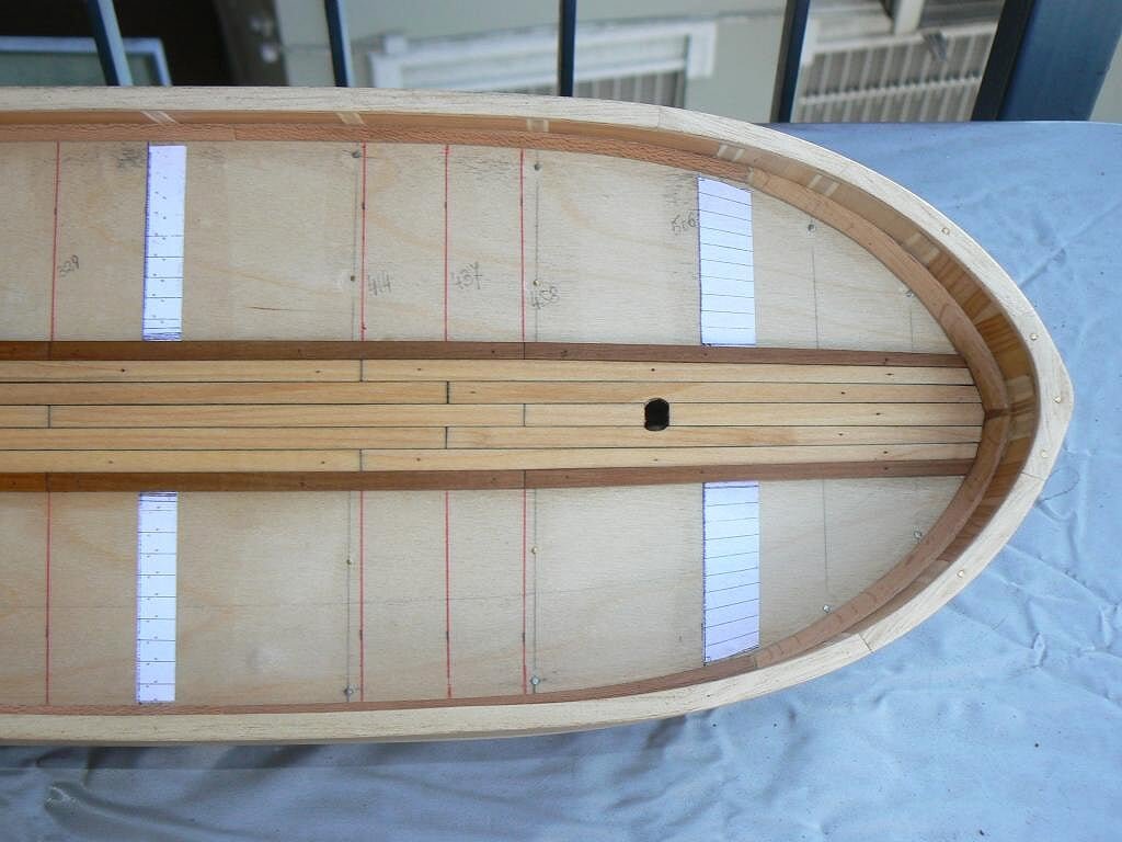
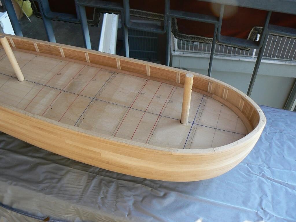
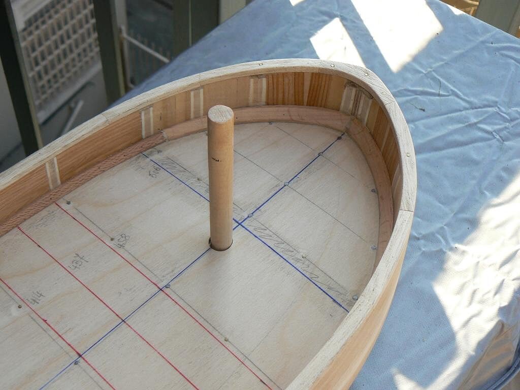
And three more detailed views . .
02 Brick%20by%20JackAubrey/P1100163_zps2dae1e76.jpg
03 Brick%20by%20JackAubrey/P1100162_zps1ef0e477.jpg
04 Brick%20by%20JackAubrey/P1100161_zpsa932a341.jpg
See you next time, Jack.
-
Posted: Sat Feb 23, 2008
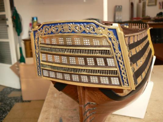
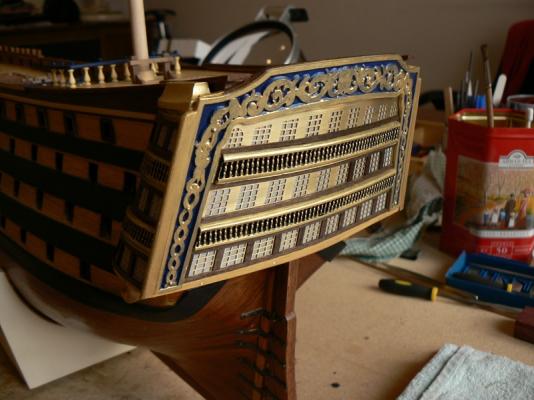
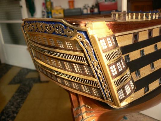
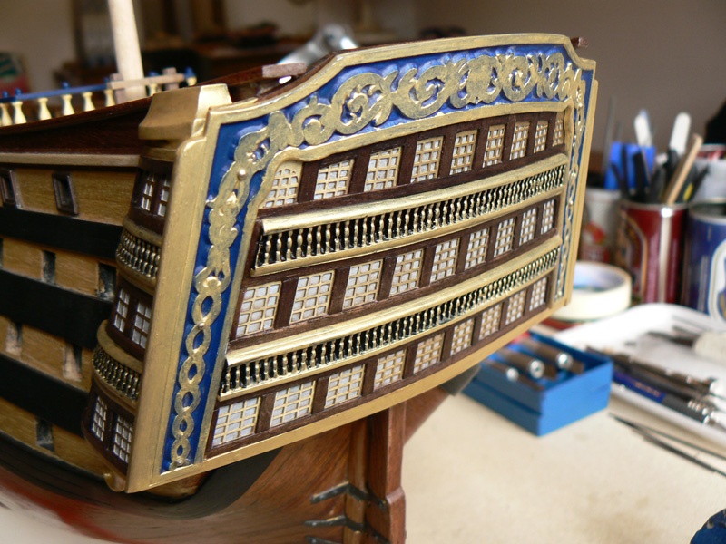
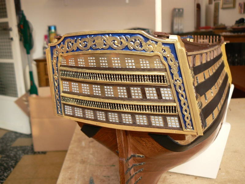
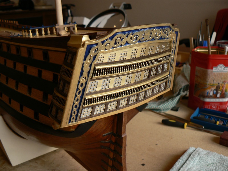
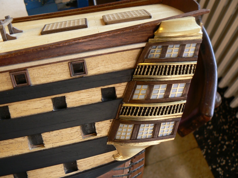
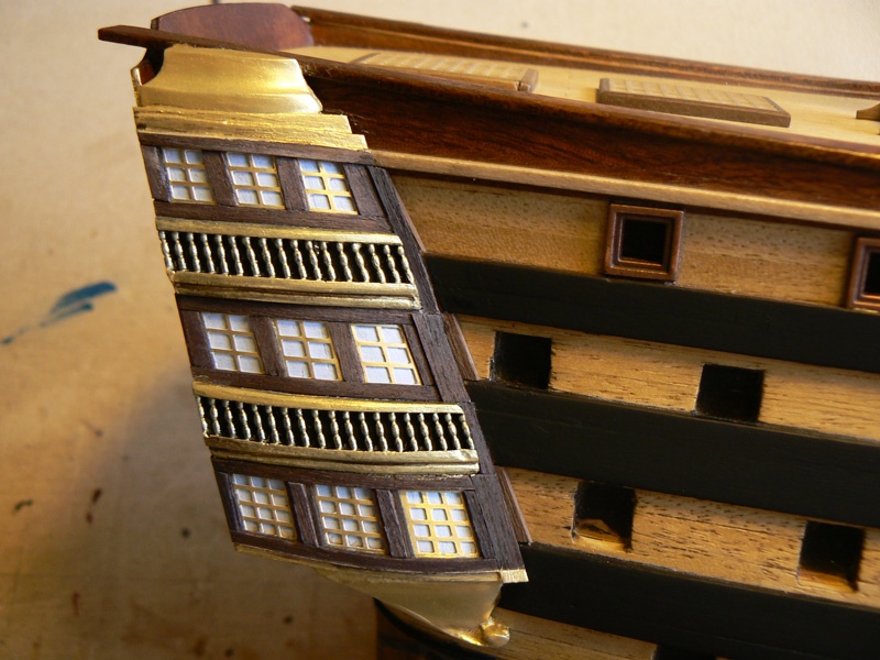
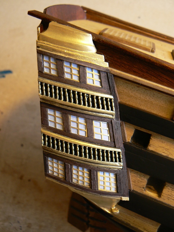
Here are the latest images, shot today Feb. 23rd, of the stern galleries. I have finally completed the installation of the windows wooden frames and I have applied the gold enamel where necessary.
The work is finished at 98%, the only thing remaining is the aged look and feel. I have no experience about these techniques so I need to document myself and, once find one I like, make some tests and go further.
Apart the aging, now I have to start working on some completely new things. The instructions give me several choices: from the poop rails to the head, including the figurehead, passing through the channels, deadeyes and chains. Another task can be the definitive installation of the guns. So I have plenty of choices to select and the only need is to find and dedicate enough time and efforts to achieve results.
I hope to be back early with new things to show you. Jack.


- cristikc, WackoWolf and CaptainSteve
-
3
-
. . Are the bow pieces built by two battens that you have bent and fine-shaped with the band saw or are they cut from a tablet?
. . And what about the gunwale? Is it definitive?
The bow pieces of the waterways are done starting from a beechwood tablet, shaped with the band saw and the power sander.
Regarding the gunwale, I believe the answer you want can be found in my previous message, isn'it ?
The real gunwale will be installed later, after the 2nd planking and after having opened the gunports. If I well remember should be around 2mm height.
Cheers, Jack.
-
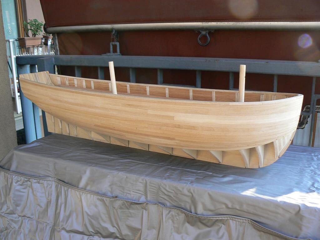
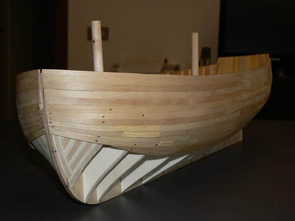
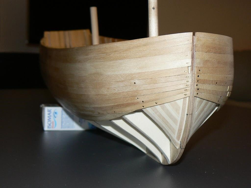
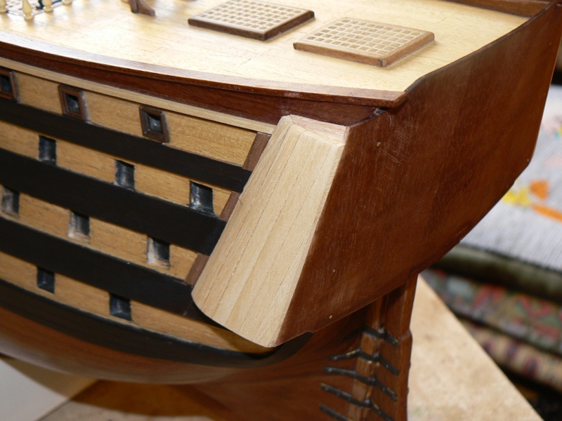
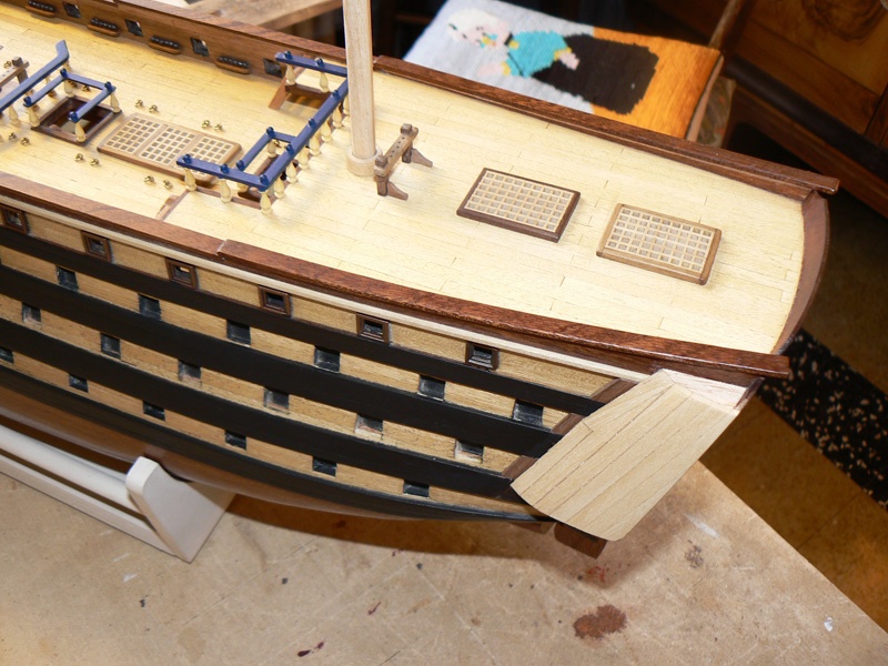
Yesterday I closed my message writing that I had to do a unexpected work due to an error in the initial design of this model. I omit the explanation about the reasons causing the error, of course totally due to myself. Instead I want to describe its effects on the hull and the action to be taken to correct it.
When I finished installing the waterways I realized, re-measuring the height of the interior bulwarks, that these were 4 mm lower compared to what had to be in reality: the height of the bulwark measured from the waterways had to be 24 mm. while it was only 20.
After an initial moment of discouragement I developed a corrective solution that I think was well deployed, considering that it is expected a double planking.
I cut with the table saw, from a wooden board exceeded after the mounting of the building slip, three strips 4 x 20 mm. I used them to draw and cut out shapes to apply over the bulwarks.
In the picture below you can see how this new element, similar to a gunwale, has solved the problem.01 Brick%20by%20JackAubrey/P1100148_zps7a608abc.jpg
The only drawback: I had to do quite a lot of dust; my power sanders Proxxon BSL 220/E and OZI 220/E are true jewels but, as dust producers, are incredible. So I had to spend the end of the day to suck all my workshop . .
I enclose other images to complete the message . .
02 Brick%20by%20JackAubrey/P1100149_zpsed4c1dd0.jpg
03 Brick%20by%20JackAubrey/P1100146_zps2f486aa3.jpg
04 Brick%20by%20JackAubrey/P1100144_zps67c0a138.jpg
05 Brick%20by%20JackAubrey/P1100143_zpsfeb94fa3.jpg
See you at next episode, where I strongly hope to describe the beginning of the installation of the deck planking . . Regards, Jack.
-
Friday, December 19, 2014
After spending the last week to experiment in search of the most suitable timber for the deck planking and having tried a couple of methods to simulate the caulking, this week I dedicated myself to perform some preliminary tasks to deck planking.
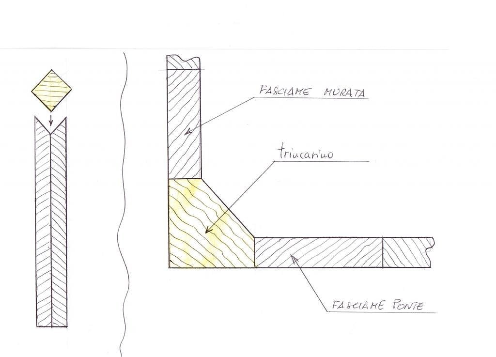
First, it was evident the need to first install the waterways. Last week I prepared a simple tool to hold the wood strip at an angle to be able to smooth on one side giving him the classic triangular shape.
The first image here below, in fact a drawing, shows on the left this "tool".
It is formed by gluing together two pieces of plywood that have been cut on a side at 45 degrees. Glued as shown by the design they formed a stable base on which to place the square wood strip I needed to obtain the waterways. I used the Proxxon sanding disc to level the part to be removed.Also on the right of the drawing it is shown the shape of the waterways, which is not triangular, as at first glance you might think but must take into account the thickness of the planks of the deck and bulwarks, to be applied later.
01 Brick%20by%20JackAubrey/Trincarinoeattrezzino_zps42a286f0.jpg
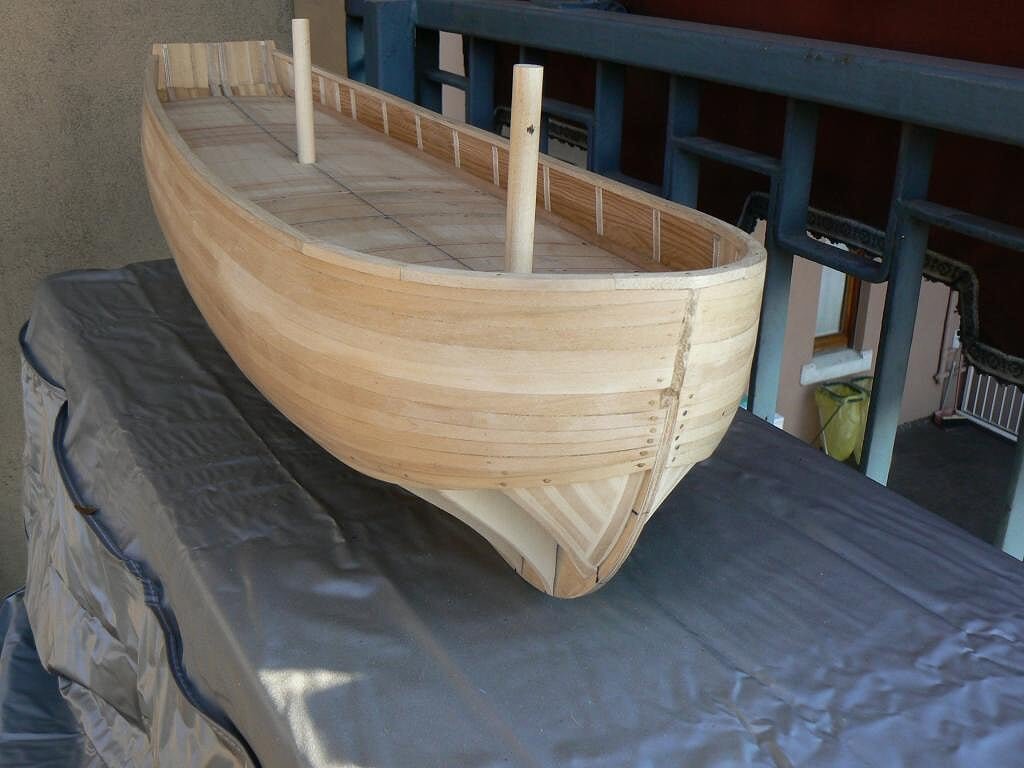
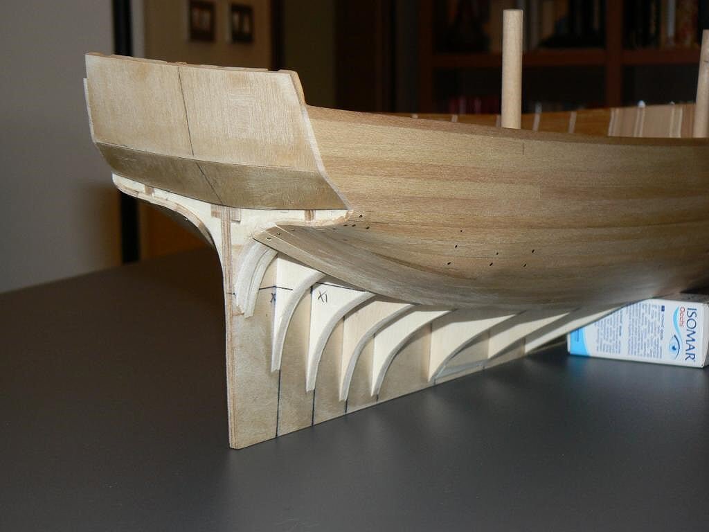
Here are some pictures with the waterways installed. .
02 Brick%20by%20JackAubrey/P1100147_zps4ba5dc60.jpg
03 Brick%20by%20JackAubrey/P1100139_zps25683f74.jpg
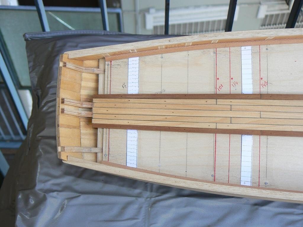
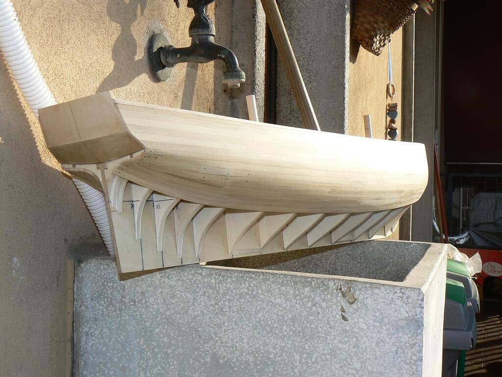
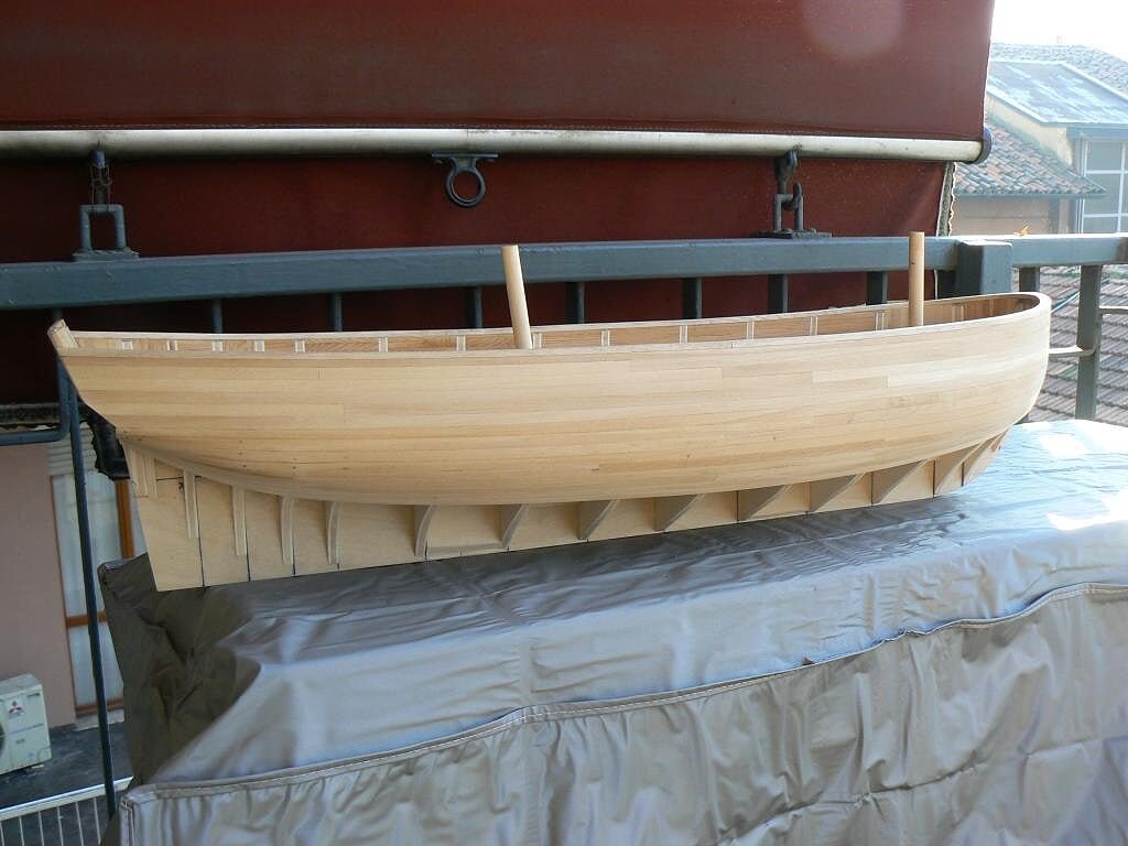
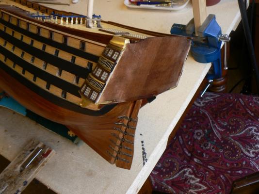
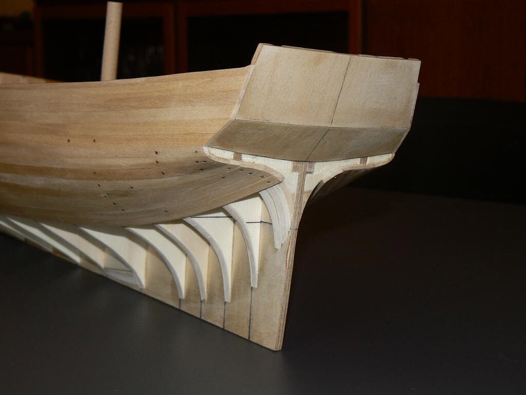
A peculiarity of this waterways, which led to a job quite long and complex is at the bow.
As for the rest of the hull it was enough to use a strip of beechwood suitably shaped, the part at the bow, visible in the picture below, has had to be constructed in a completely different way.
A part the curvature, here the waterways starts with a dimension of a square 4 x 4 and ends at the tip with a size of 5 x 9. This is because in the waterways, at the bow, will be located the holes for the hawse-holes. For this task, building this segment of the waterways, I got to do a "creative" use of the band saw.04 Brick%20by%20JackAubrey/P1100142_zps59099497.jpg
See you soon with a new task I did'nt absolutely expect, due to a initial design mistake. Regards, Jack.
-
Posted: Fri Feb 22, 2008
The work on the stern galleries is progressing slowly, but it's anyway better than nothing . . . .
In this period I'm undertaking several interests that are diverging my mind from ship modeling: in the last 15 days I spent very few time working on my models.
From the other side more of my time was focused on finding a car for my daugther (at the end I decided for a new one), a home helper for my mother (87 years old) and in reviewing and deciding the venue where to spend my next summer holidays.
The images here attached, shot yesterday Feb. 21st, show the work-in-progress on the stern: I'm applying the wooden frames at the windows. Today I have made another few progress but it's now sunset and there is not enough light for taking good photos.
See you tomorrow .. Jack.

- CaptainSteve, WackoWolf, yvesvidal and 1 other
-
4
-
Posted: Sun Feb 10, 2008
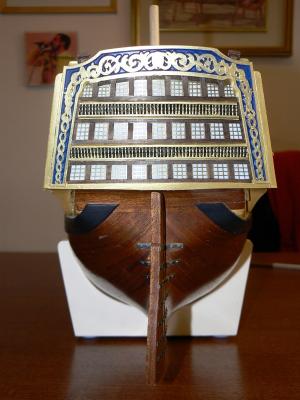
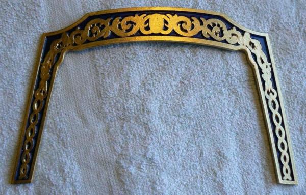
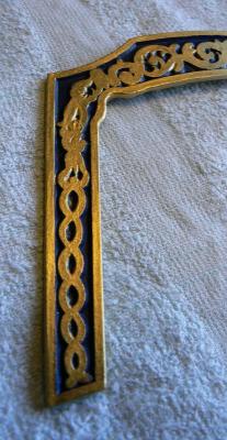
My first attachment shows the next battlefield: the stern galleries.
After the experience I made with the quarter galleries I believe this new task will be a much simpler battle . . . but I'm ready for any kind of hazard . .
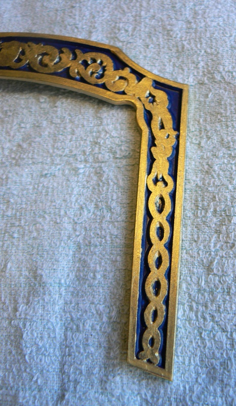
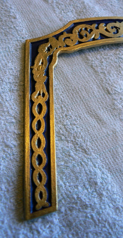
The other images show one of the main pieces of the stern galleries, made with a cast metal that can be easily manipulated and adapted to the surface where to position it: the stern frame (or framing ?).
Before to install it, it's better to paint it, it's much simpler now than once mounted in place.
First I have applied a coat of blue paint and after two (for the moment) coats of golden paint. The gold paint is applied with a "customized" brush, with the bristles cut very short. The brush is used "quasi" dry to avoid painting the area that needs to remain blue.

- CaptainSteve, yvesvidal, WackoWolf and 1 other
-
4
-
Posted: Sat Feb 09, 2008
These are the quarter galleries of the larboard side of the ship.
If you compare the same images from the other side of the ship you will easily note that here the upper quarter gallery support fits a little differently in its place.
I tried to remodel the metal piece (when seen from the top it has a different curve and shape vs the other) but it wasn't possible to obtain a shape equal to the starboard side. Hindsight it should be better to scratch build it for an hard wood block but ... now it's too late.
This problem is a symptom of the poor quality of the cast and I believe it's a common problem you can find in the most commercial kits. Another arrow in the quiver of scratch building ....
Regards, Jack.
-
Posted: Fri Feb 08, 2008
I'm still working on the poop galleries. It's a never ending story . . .
The new work around the stern side galleries consisted of several things; first of all I realized that the ivory color paint I applied on the windows frames (made with brass and in accordance with the instructions) was at risk.
I wasn't sure the paint was able to remain strongly achored to its brass ground using the cyanacrilate glue, so I decided to remove it and to come back to the original natural brass.
This means that my Santìsima Trinidad will have golden window frames instead of cream . . a good point of personalisation.
Second I had to apply around the window frames some wood strips that are clearly visible in the attached images.
This was a work of great patience but nothing more. As anticipated I used the cyanacrilate glue for this task.
Last I had to apply the two upper galleries supports. They were made of cast metal and, again, they didn't fit at all in their place.
So with time, a lot of patience and a file I removed the exceeding metal to make them fit properly. To fix definitely them I used the bi-component epoxy.
Later I finished the whole areas by painting with gold both the lower than the upper galleries supports. I also tried to age the golden parts but my efforts were not enough and it is now quite invisible. I have to find a better aging method.
I believe that the proposed images here below are much better (in terms of quality and colors) them the same I attached to my previous message: here the colors are influenced only that the winter light, nothing else. . .
Kind regards. Jack.

- yvesvidal, CaptainSteve, WackoWolf and 1 other
-
4
-
Posted: Wed Jan 30, 2008
The works around the stern side galleries are progressing slowly, but this was forecasted. At this stage you have to proceed with extreme care, expecially to ensure a correct alignment with the decks (or better where it is supposed they are).
Next step will be to apply the woodden frames to the windows . . .
Some paint retouch will be then necessary at the end but it's still a long way. And at last there are the stern central galleries, much more complex but hopefully of great satisfaction.
The quality of these four images is not the maximum, mainly due to the poor light available or the bad guy behind the camera. Probably the last two images are the better in terms of color.
See you next time. Jack.

- WackoWolf and CaptainSteve
-
2
-
Posted: Sun Jan 27, 2008
I have recently found, surfing on the net, the complete plans of the Santìsima Trinidad. These plans are for the "Occre" kit but are also perfect for mine. In fact my model, published on a weekly magazine by DeAgostini, is an enhancement of this spanish kit.
The availability of these plans is of strategic importance for me and other people building the same model from DeAgostini because the latter doesn't supply any kind of plans. So you can understand the great benefits of having them, especially for the future rigging activities. It also can help very much in foreseeing/understanding some works and consequently plan better the future tasks.
I want also take advantage of this message to explain and show you my last works. They are very small details on the ship but very, very difficult to achieve.
1) Installation of the two lower gallery supports: they are made with cast metal and, as usually, do not absolutely fit in their place. I have spent two to three hours in adapting them and their cradles in order to achieve an acceptable result. Finally I have definitely mounted them using epoxy glue (very strong). Anyway there where many long narrow openings that I had to fit and fill with small pieces of wood. Last, the usual final refinemens and three coats of golden paint.
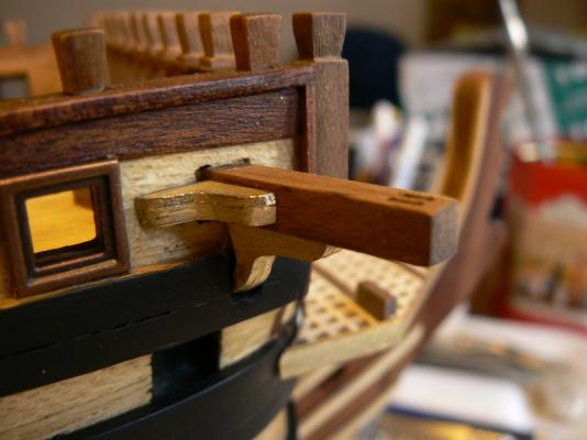
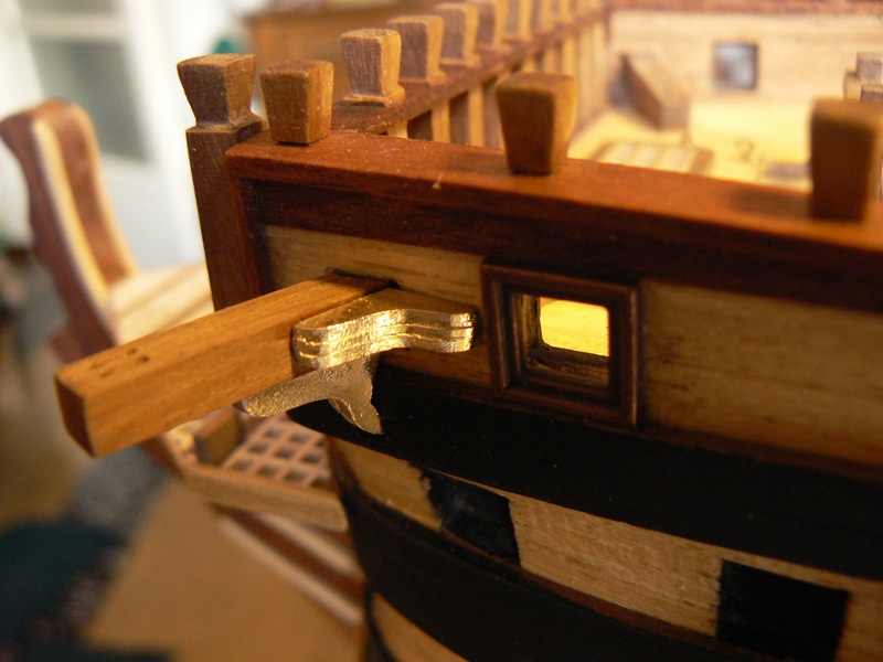
2) Installation of the catheads and its supporters. The holes in the hull were previously done but I had to adapt the whole to match the right angle (determined by the two horizontal cathead supports made with cast metal). Here I have some images to show you detailing this latter work.
That's all for today. See you next time. Jack.


-
Posted: Fri Jan 25, 2008
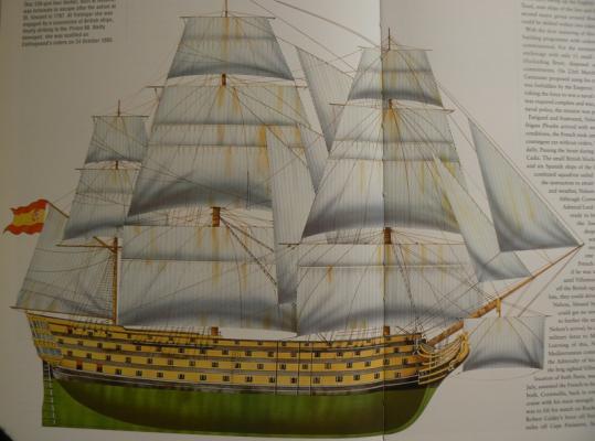
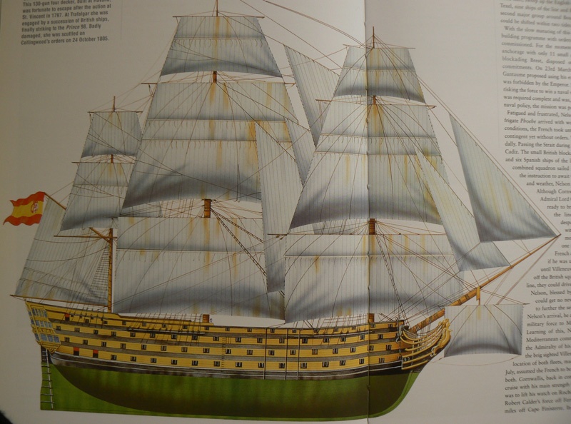
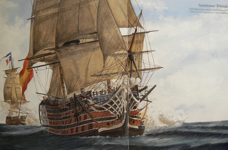
I have found two pictures of the Santìsima Trinidad in two different books. The first one is more similar to a plan and shows the ship probably in its pre Trafalgar livery, with black wales and yellow between them. The hull seems also a little different vs my model in the area of the forecastle and the poop deck. Also the rigging seems different: three yards for each mast instead of four . . .
The second one is more pictorial but most probably shows the ship livery during her last battle, where she was greatly damaged, captured and sunk.
I don't think to adopt one of these liveries for my model but I post these images hoping they can be useful to understand better the history of this ship or to another modeler who prefers finishing his own model in this way.
Kind regards. Jack.Aubrey

- CaptainSteve and WackoWolf
-
2
-
Posted: Thu Jan 24, 2008
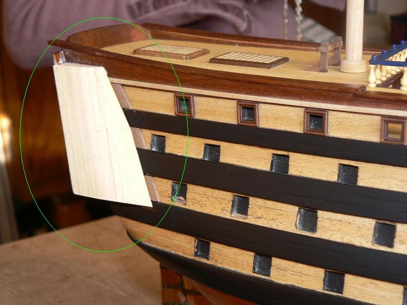
January 24th, 2008 - The stern galleries
Having, for the moment, finished to work around the rudder, I started a new task: the stern galleries and decorations. This will be a long and complex work, so I don't expect a quick final achievement in the near future but a lot of step by step intermediate milestones towards the final objective.
The first step to do is to build two structures on the hull sides. These structures will became the background of the right and left quarter galleries: the work consists of 1) preparation and 2) installation of three bulkheads per side that will be later planked vertically with strips of mm. 2 x 5 of ramin wood.
The first image shows, highlighted in the circle, the starboard side gallery structure when finished and sanded. This was the first I have built and I started planking from left to right. The result of this method was some troubles on the right portion of the structure where I had to perform additional refining work to achieve a reasonnable result. Anyway the result sounds good to me.
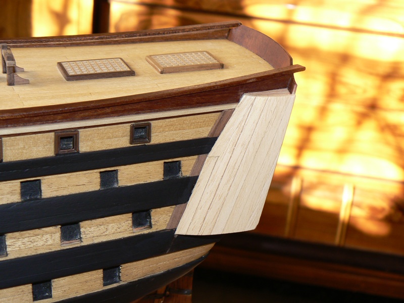
The second image shows the same structure on the larboard side.
Here I adopted a different method of planking: I started from the left, applying two shorter planks before, then a second plank on its right side with a blunt-ended upper side, and finally all the other planks to cover the structure until its end. Very much simple and quick: power of the experience . . . sometime I believe one should build at the same time a model twice to obtain the perfect one . . . the first to make experience and the second to make excellence . . .
That's all for today. See you next time. Jack.Aubrey


- CaptainSteve, WackoWolf and yvesvidal
-
3
-
Thursday, December 11, 2014
I did other tests with the planking for the decks . . also because I did not have much time to do other.
In addition to the test I made a few days ago with strips of oak, I tried with the limewood and the Tanganyika. I've always approached two solutions, graphite and bristol paper/card, but, regarding bristol, I used a more thin type compared to the first test.
The result is more delicate that before. Also graphite method on limewood achieves virtually the same final result.I'm thinking to proceed in the following way:
- 5 strips of oak with bristol paper for the central part of the deck;
- 1 strip of Tanganyika per side as the master plank;
- several strips of limewood for the external sides, using graphite, being the result almost similar but the application is considerably more simple.Eventually, as a variant, I could plank also the central part with limewood. The Tanganyika is too dark and there are too many differences in color between strips.
Now I'm thinking about how to make the waterway, task to be made before the deck planking. I'll start with a square 4 x 4 or 5 x 5 beechwood that needs to be properly shaped with an equip I am preparing, hoping that it works.
Hello, Jack.Aubrey.
. . oak wood . .
01 Brick%20by%20JackAubrey/P1100134_zpsb5399f99.jpg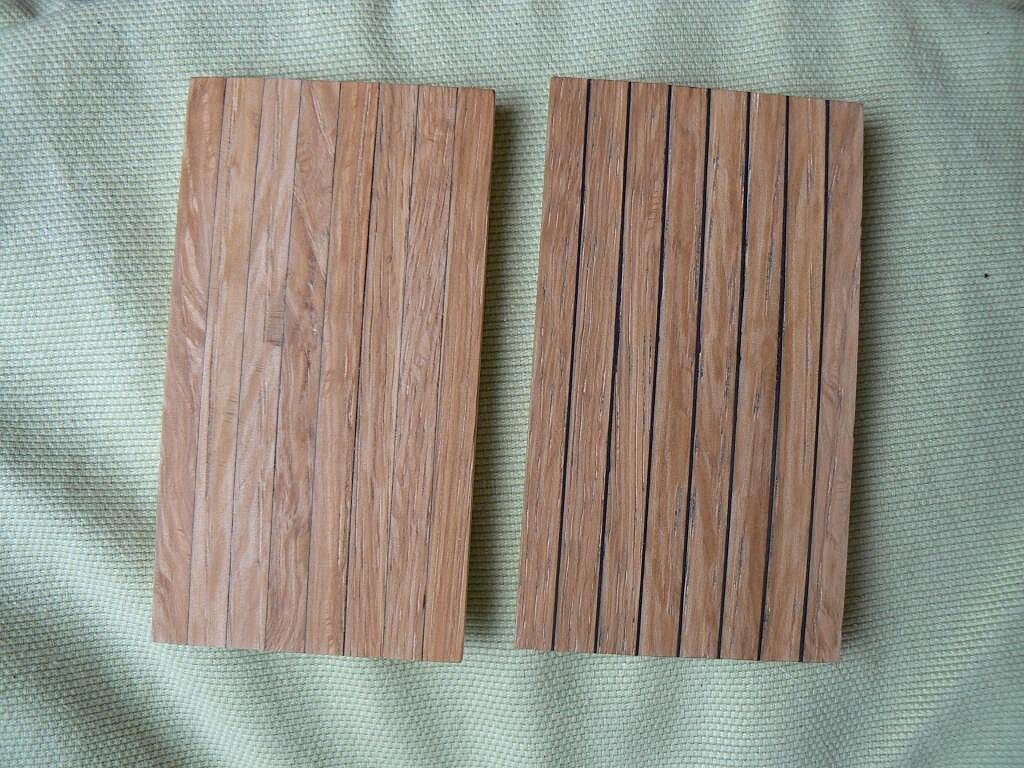
. . limewood . .
02 Brick%20by%20JackAubrey/P1100133_zps700482fd.jpg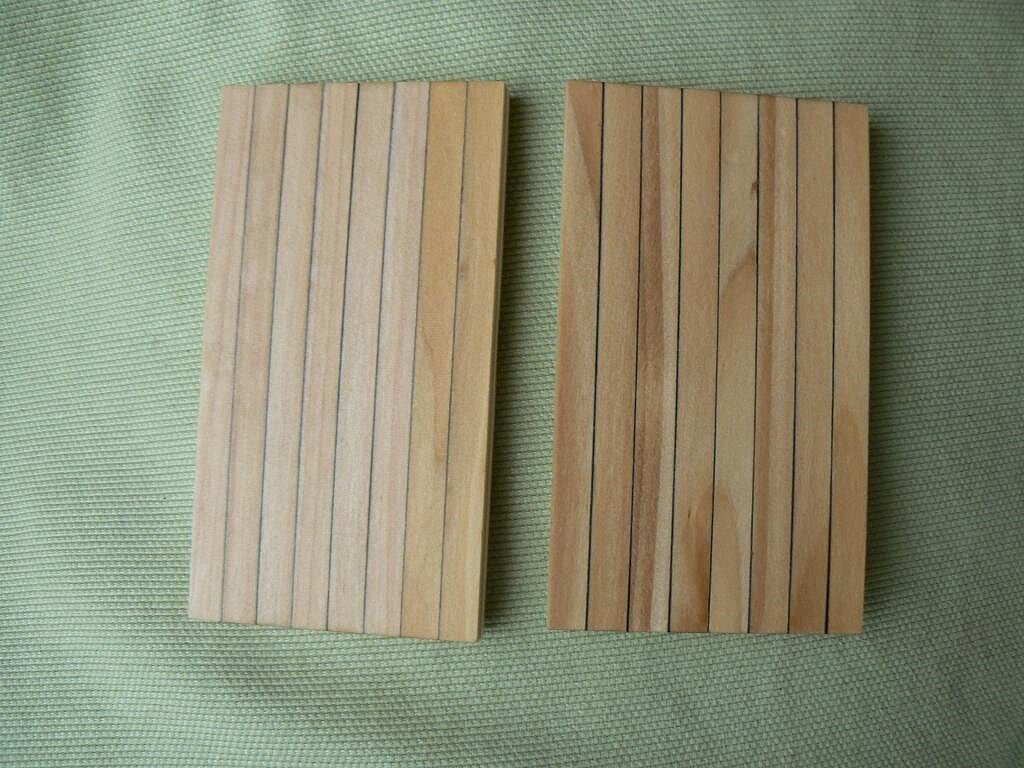
. . tanganyika . .
03 Brick%20by%20JackAubrey/P1100132_zps1ef48220.jpg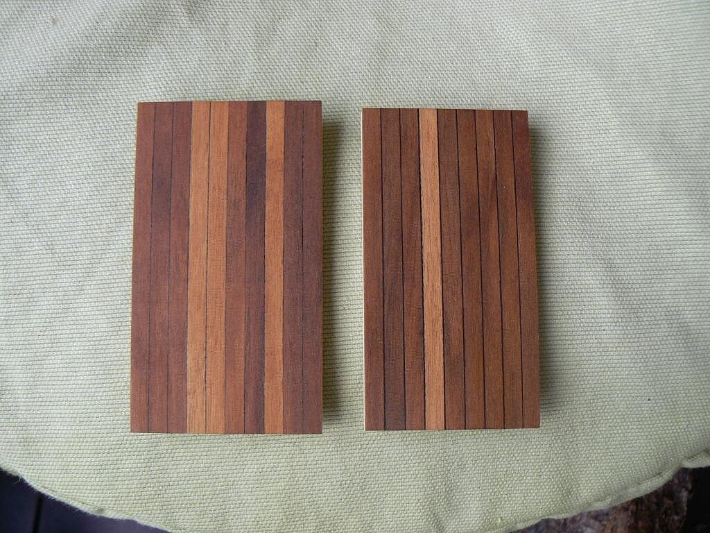
. . all together . .
04 Brick%20by%20JackAubrey/P1100135_zpsa1362381.jpg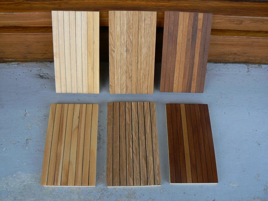
. . al together with flash light . .
05 Brick%20by%20JackAubrey/P1100137_zps5d7870c5.jpg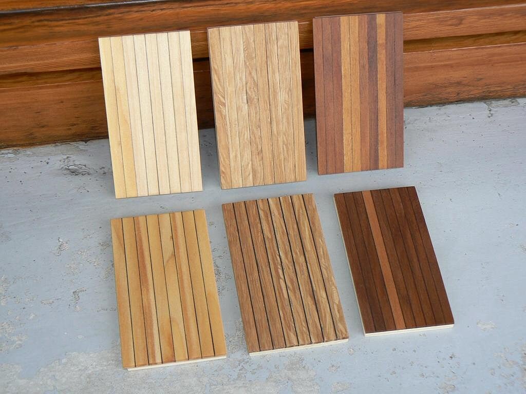
-
Posted: Fri Jan 11, 2008
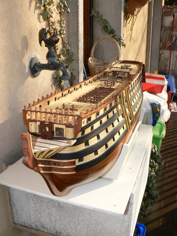
Yesterday there was a sunny day here in Milan, after a lot of days of snow, rain or clouds. So I took the opportunity and I shot some new photos from the terrace of my house to my favorite vessel.
As special gift of the new year I attach here some of them.
Kind regards


- yvesvidal, CaptainSteve, WackoWolf and 1 other
-
4
-
Posted: Fri Jan 11, 2008
These images show the rubber area after the application of a final coat of transparent matt varnish (polyurethane enamel: http://www.drtoffano.com/toffano_prodotti/pg_prodotti.htm(italian web site)). This is a special varnish specific for modelers.

-
Posted: Thu Jan 10, 2008
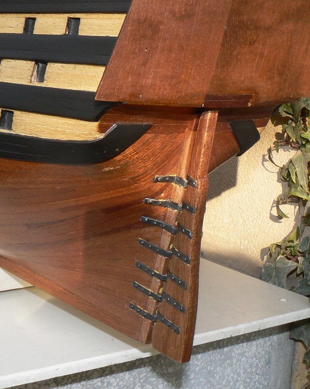
Today, being the gun metal paint completely dry, I have removed the masking tape from the rudder and the result can be seen in the next two photos.
The work is not yet terminated because now I need to perform the final cleaning of the few places where the paint is penetrated below the tape but it is a quite simple task.
Last I have to apply a coat of transparent, matt paint.
This for two reasons: 1) I don't like the gloss finish and 2) I have to recover the wooden areas around the straps that I damaged during the istallation of the rudder.
Kind regards. Jack.
- WackoWolf and CaptainSteve
-
2
-
Friday December 5, 2014
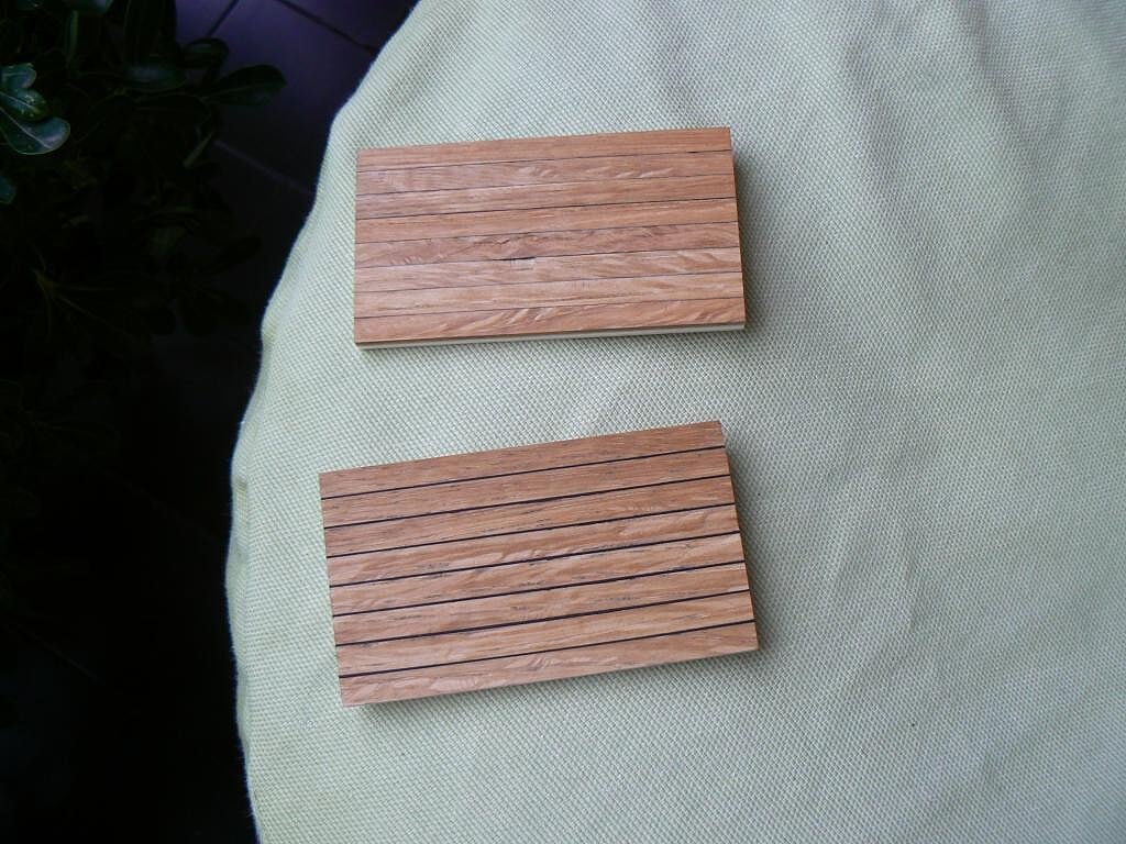
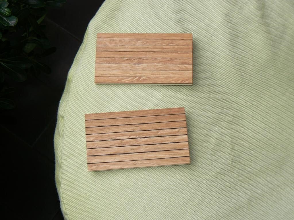
Yesterday was a indeterminate day and I decided to do some tests to simulate the caulking of the deck.
I enclose a couple of pictures with two samples obtained with two different methods.
The first image was shot in "natural light", if we can call "natural" the gray sky due to these rainy days, for the second I used the flash: there is a noticeable colors difference . .upper sample: I used graphite. I bought a pencil with the softer tip available on the market. Also the charcoal was available but it did not seem fit for purpose. I very carefully blackened the the thickness side of the strip.
lower sample: between a strip and the other I put a strip of black "Bristol board". The application is more complex and also the final polishing is not less. But if you use card strips of the same height of the wood strips it works much better.
PS: the strips are the ones that I would most probably use, oak wood, and are already treated with wood oil, then this will be the final color. The grain is rather coarse, perhaps too much, but I really like it. This wood strips are also very, very hard . . As possible alternative to oak there is the lime wood, where probably the first system of caulking should give a more appreciable result. With oak wook I prefer the second. Probably I'll need another similar test with lime .
What do you think ?
Regards, Jack.
01 Brick%20by%20JackAubrey/P1100108_zpsd5033587.jpg
02 Brick%20by%20JackAubrey/P1100109_zps32a83b81.jpg
-
Since I still uploaded more photos on the "photobucket.com" site and it costs nothing to show, I add a few more additional images of the brick, taken on the same day of the last messages.
The heads of the brass nails were leveled and do not bother, so I do not intend to remove them. With the second planking they will disappear. Jack.
01 Brick%20by%20JackAubrey/P1100098_zps3d70a4a9.jpg
02 Brick%20by%20JackAubrey/P1100101_zps59a0efdd.jpg
03 Brick%20by%20JackAubrey/P1100099_zps3c77c405.jpg
04 Brick%20by%20JackAubrey/P1100100_zps6c580ebb.jpg
05 Brick%20by%20JackAubrey/P1100097_zps43c4da21.jpg
-
Posted: Wed Jan 09, 2008
Further work on the rudder.
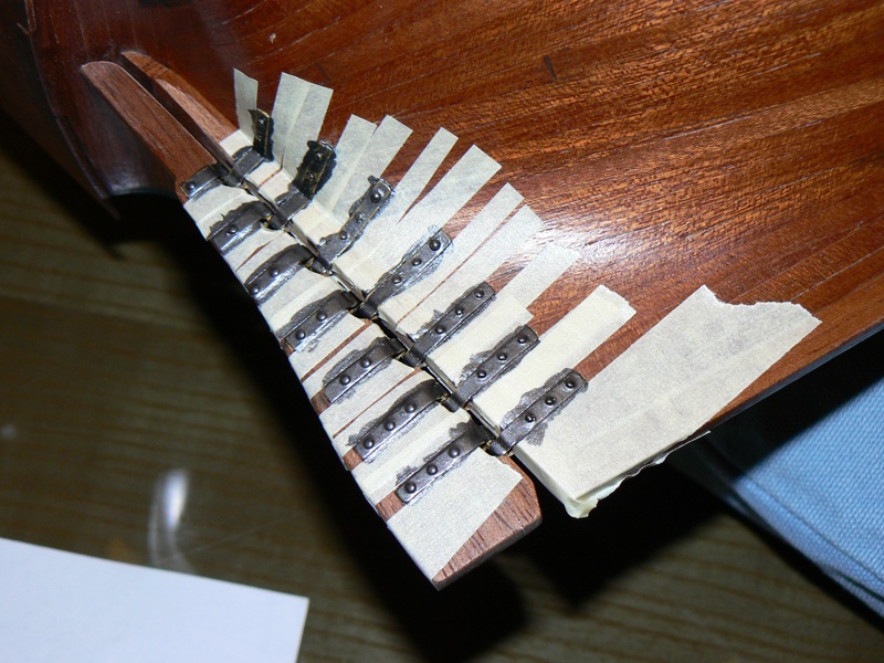
Some days ago I coated with a primer (yellow) the straps and today, being them completly dry, I started to prepare the area for the final color.
To do so I used some stripes of masking tape in order to protect as much as possible the surface not involved in painting.
The first image shows the area protected with the masking tape and the second with a coat of Gun Metal applied. I had to wait a couple of hours for drying and then I applied a second coat. I think that gun metal is much more realistic than copper for the straps.
In the next message the final result.


Santìsima Trinidad by jack.aubrey - De Agostini - Scale 1:90 - Full Model
in - Kit build logs for subjects built from 1751 - 1800
Posted
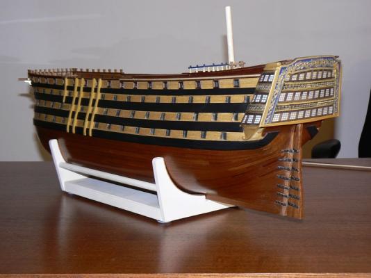
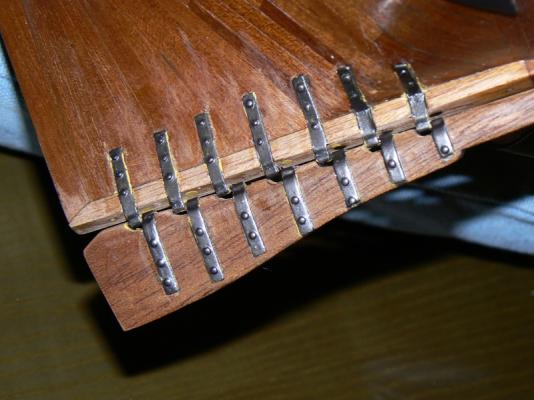
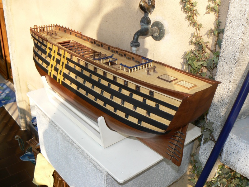
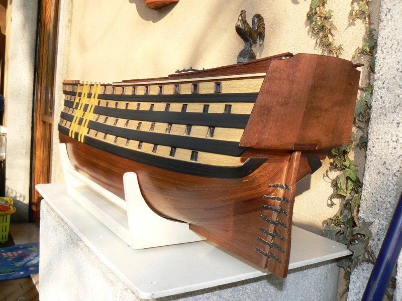
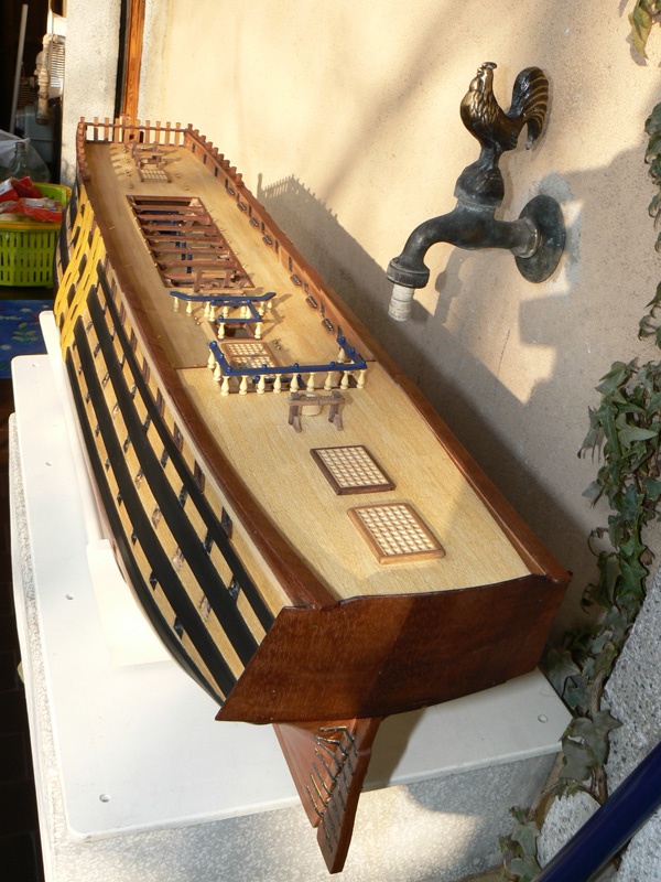
Posted: Tue Mar 04, 2008
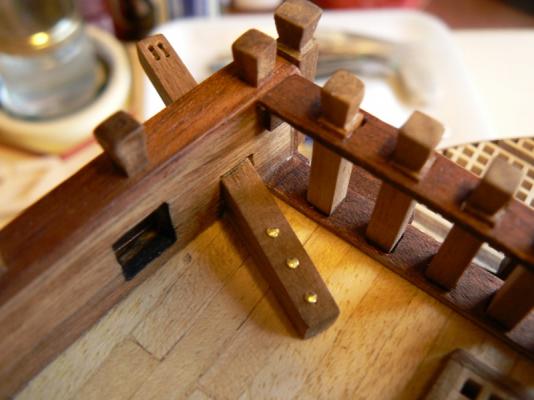
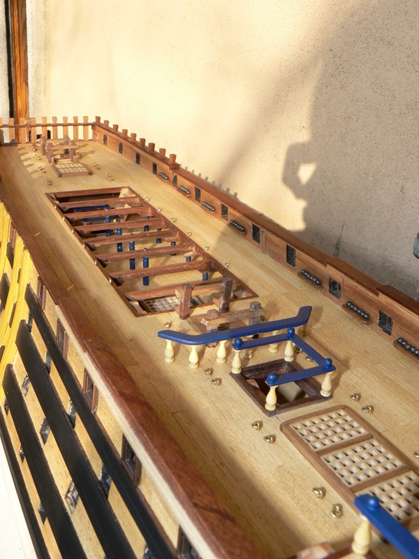
Yesterday I have completed another interesting task: the construction of the poop rails.
To achieve this (for me) good result I did not follow the kit instructions but I used a different method and different materials.
First of all the small columns I used. They were not supplied by the kit manufacturer (the supplied was a brass rod to be cut at the proper length). The columns I used were a remainder of a previous kit (Le Mirage from Corel built by me 30 years ago).
The first image shows these small columns.
Second, the total number of columns used, I used more or less twice the number suggested by the kit.
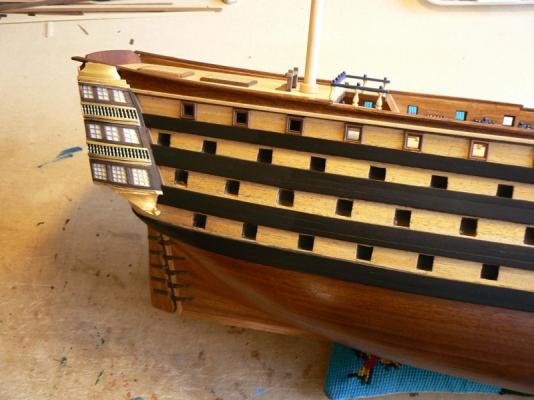
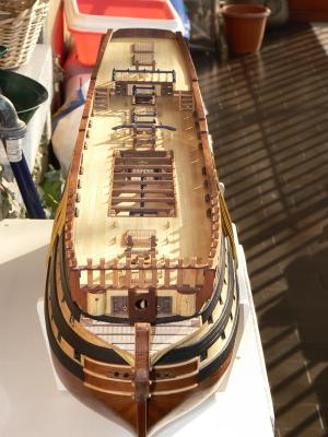
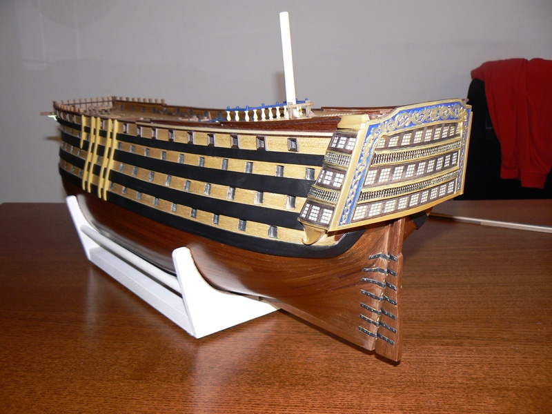
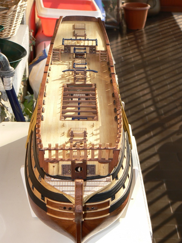
The last image is an overall overview of the ship. You can also see that I have painted in black a part of the side ladders.
Regards. Jack.Aubrey