


jack.aubrey
-
Posts
1,268 -
Joined
-
Last visited
Content Type
Profiles
Forums
Gallery
Events
Posts posted by jack.aubrey
-
-
Posted: Thu May 03, 2007
Another step in the history of this great ship ....
1781: Còrdoba took Santìsima Trinidad to sea again on 23 July and joined forces with the French fleet of 20 sail under Admiral the Comte de Guichen. Now comprising over 50 warships, the intention of this combined fleet was to recapture Minorca. Over the next few months Santìsima Trinidad was involved in the capture of a British convoy off Sisargas and supported the blockade of Gibraltar from Algeciras. Returning to Cadiz on 23 September, Santìsima Trinidad went into dock on 5 October to have her hull careened and her bottom coppered in compliance with recent legislation authorised by the Spanish navy.
1782: After Santìsima Trinidad was undocked on 23 April she rejoined the combined Franco-Spanish fleet and took part in the battle against Admiral Lord Howe’s fleet off Cape Spartel on 20 October. During this action the ship suffered one man killed and four wounded.
1783: After peace had been signed on 23 April, Santìsima Trinida returned to Cadiz where she was withdrawn from service although she remained under the command of Brigadier Pedro Autràn.
1796: Under Brigadier Rafael Orozco’s command and flying the flag of Admiral Juan Làngara, Santìsima Trinidad sailed from Cadiz with a squadron for the Mediterranean, cruising off Corsica and Italy. Going into Toulon in November, she sailed again in October, escorting Rear-Admiral Villeneuve’s ship bound for Brest. Having cleared the convoy, Santìsima Trinidad went into Cartagena on 20 December. Command of the Spanish squadron was now superseded by Leutenant-General Don Josè de Còrdoba y Ramos who hoisted his flag in the Santìsima Trinidad, although Orozco still held command of the ship.
1797: Receiving orders to sail for Cadiz, Còrdoba put to sea on 1 February with his fleet, comprising 27 ships of the line, twelve frigates, a brigantine and some smaller vessels. After re-provisioning at Cadiz Còrdoba’s fleet was to sail for Brest where it would join forces with the Dutch and French squadrons already assembled to invade England.
Besides Santìsima Trinidad the other ship that had sailed from Cartagena with Còrdoba on 1 February which would later fight at Trafalgar were Principe de Asturias (112), Neptuno (80), Bahama (74), and San Ildefonso (74).
The Spanish fleet fell in the Admiral Sir John Jervis squadron of 25 ships off Cape St Vincent on 14 February.
In the ensuing battle, Santìsima Trinidad was simultaneously engaged under concentrated fire from the 74 gun ships Blenheim, Excellent, Irresistible and Orion.
Despite her greater size and firepower Santìsima Trinidad would have struck her colours had it not been for the intervention of Real-Admiral Cisneros who arrived in time to give support and draw off British fire.
Under fire for nearly five hours, Santisima Trinidad sustained heavy damage, she was totally dismasted and her larboard side had been virtually destroyed.
Moreover she had been hulled by 60 round shot below the waterline causing her to take in three feet of water per hour. Her casualties amounted to 69 dead and 407 wounded.
While Còrdoba transferred his flag into the frigate Diana, Santìsima Trinidad under jury masts was partially escorted by the frigate Mercedes towards Cadiz.
After losing contact with Mercedes the ship was sighted by another British squadron en route. To avoid action, Captain Orozco hoisted British colours above the Spanish so the patrolling ships would think she had British prisoners on board. The subterfuge worked and the ship was able to get into Zafi, Morocco, where she remained until making sail again on 28 February.
That night Santìsima Trinidad was attacked by the frigate Terpsichore which was driven off by her four 24 and 36 pounder stern chase guns. She received more damage and suffered one man killed and five wounded.
Santìsima Trinidad finally reached Cadiz on 3 March.
Once in port Admiral Josè de Mazarredo, captain-general of Cadiz, questioned Santisima Trinidad ability in battle against smaller ships. Having also found her unseaworthy, Mazarredo proposed that Santìsima Trinidad be beached at Cadiz as a defensive gun platform.
Mazarredo’s recommendations were however overruled and the great ship was refitted and laid up until 1804.
1799: Because she had been extensively damaged during the battle of St. Vincent, Santìsima Trinidad had to go into dock in February for extensive repairs and was thoroughly careened.
While in dock she was modified by extending her planking between the quarter deck and forecastle to mount more guns and consequently became the world’s only four-decked fighting ship, although this alteration further compromised her sailing quality and handiness.
Already a colossal three-decked ship of 120 guns with a broadside weight of 1,204 pounds when built, she now had 16 additional gun ports.
When rearmed on 12 February this allowed her to mount six 4 pounder carriage guns in her waist and ten 24 pounder carronades on her forecastle.
This increased her a total broadside weight of fire by 132 pounds to 1,530 pounds. In all her firepower was 25 per cent greater than Nelson’s Victory.
Santìsima Trinidad’s dimensions at this time ware recorded as follows:
Length of the range of the gun deck: 63.36 m.
Length of keel for tonnage: 54.02 m
Extreme breadth: 16.67 m
Depth in hold: 8.26 m
Floor of the hold: 8.57 m
Displacement: 2,475 tons
Ballast: 20,000 quintals
Complement: 1096
Ordnance – lower gun deck: 32 x 36 pounders
Ordnance – third gun deck: 34 x 24 pounders
Ordnance – second gun deck: 36 x 12 pounders
Ordnance – quarter deck: 18 x 8 pounders
Ordnance – waist: 4 x 4 pounder howitzers
Ordnance – forecastle: 10 x 24 pounder carronades
Single broadside weight: 1,300 pounds
Note: Clowes lists Santìsima Trinidad as being armed with 130 guns which implies that the ship did not have the six 4 pounder carriage guns mounted in her waist until after 1797; therefore her broadside weight would have been marginally less than 1,530 pounds at this time.
1804: When Spain allied herself to France and entered the war against Britain, Napoleon virtually doubled the size of his operational navy to support his plan to invade England. Fitted for sea Santìsima Trinidad was placed in commission under the command of Don Francisco Javier de Uriarte y Borja.
1805: Lying in Cadiz harbour ready to sail with Villeneuve’s combined fleet, Santìsima Trinidad clearly stood out from her consorts.
Besides having four gun decks, her sides were painted, according to Lieutenant William Lovell serving on British Neptune (98-gun) at Trafalgar, ‘ …. with four distinct lines of red, with a white ribbon between them …. ’.
After hoisting the flag of Rear-Admiral Bàltasar Hidalgo de Cisneros, Santìsima Trinidad sailed from Cadiz with the combinet fleet on 19 October, Captain Uriarte in command.
Only Santa Ana (112) with her completely black hull could equal her majestic appearance.
(to be continued … next Trafalgar !!)
-
Posted: Wed May 02, 2007
Second episode of the Santìsima Trinidad long history .....
Service Career
1769: Santisìma Trinidad was launched as a 120 gun ship at the Artillero Real (royal dockyard), Havana at 11.30 a.m. on 3 March and fitted for sea service. She received a royal order on 30 March to sail for El Ferrol, Spain.
Command of the ship was appointed to Captain Joaquin de Marguna Echezarreta who took up his post on 1 December.
Initially armed with just thirty-two 24 pounders and fourteen 12 pounders the ship was given a crew of 960 men.
1770: Ready for sea, Santisìma Trinidad sailed from Havana for El Ferrol on 19 February in company with the San Francisco de Paula, and anchored off Vigo on 12 April.
After repairing some damage to her fore and mizzen yards she sailed again on 9 May and entered El Ferrol six days later.
Between 21 July and 9 August Santisìma Trinidad underwent sea trials in company with the Guerrero and Santo Domingo.
While on trials she was armed with thirty 24 pounders on her lower gun deck, thirty-two 12 pounders on her upper gun deck, two 8 pounders and sixteen 6 pounders on her quarter deck and four three pounder stone mortars on her forecastle.
This gave her a single broadside weight of 998 pounds.
It was during these trials that serious concern were raised about her stability, for although she was carrying some 39,500 quintals (1,816 tonnes) of ballast, the ship listed so badly the she could not use her lower deck gun battery in calm water. After this the ship was then liad up in ordinary.
1771: On 14 March Santisìma Trinidad was taken into dock at El Ferrol to attempt to eliminate her stability problems. Besides fitting a deep false keel, the works undetaken to lower her centre of gravity and her metacentric height to improve her righting moment comprised lowering her deck housing and lowering the height of her decks. Besides this her stern post, rudder and various other items were modified including altering the steeve (angle) of her bowsprit.
1778: Placed in commission under the command of Captain Fernandoz Daoìz, Santisìma Trinidad went to sea where on 7 August Daoìz reported that she still continued to have stability problems.
1779: On 22 June Spain declared war to Britain and entered the American War of Independence. Still under the command of Captain Daoìz, Santisìma Trinidad sailed fron Cadiz as the flagship of Lieutenant-General Don Luis de Còrdoba, deployed as part of the French invasion fleet commanded by Admiral Comte d’Orvilliers.
As flagship of the observation squadron she had in company sixteen line of battle ships and two frigates. When the invasion plan was dissolved Santìsima Trinidad then served as part of the Spanish fleet blockading Gibraltar.
1780: Still flying the flag of Còrdoba, Santìsima Trinidad was involved in a number of sorties between 9 and 18 July. On 31 July she took up station off Cape St Vincent.
While on this deployment she participated in the capture of a British convoy transporting troops and supplies to both Bombay and Jamaica on 9 August.
(To be continued ….)
-
Posted: Wed May 02, 2007
As I usually like to do, I will start with some historical informations about the ship. The source of these informations are from a Peter Goodwin book. Peter is keeper and curator of the HMS Victory museum. After that I will introduce the kit and his manufacturer. Finally I will show the model.
Good reading .....
The 136-gun ship Santìsima Trinidad
Nuestra senora de la Santìsima Trinidad, meaning ‘Our Lady of the Most Holy Trinity’, was the seventh ship to bear this name in the Spanish Royal Navy. The first Santìsima Trinidad served with the great Armada sent by Philip II to invade England in 1588. The Trafalgar Santìsima Trinidad was initially built as a three decked 120 gun ship designed by Matthew Mullen, although it has been suggested that her design could be attributed to Pedro de Acosta.
Irish by birth, Mullen had migrated to Spain from England with his son Igniatius in 1750 to take up a position in La Carraca dockyard at Cadiz. Mullen had been hired along with many others to improve Spanish ship design.
When Mullen married a Spanish noblewoman in 1754 they modified their names to Mateo and Ignacio Mullàn. Ignacio soon equalled his father as a ship designer and constructor.
On 11 November 1766 Mullàn received orders to supervise ship construction in the Royal Arsenal of Havana and, before his departure in April the following year, he submitted his plans for building a large 112 gun ship.
Once San Luis (80) had been launched at Havana on 30 September 1767 work on Mullàn’s ship began but he was never to see his concept materialise. Dying of the ‘black vomit’ on 25 November 1767, the design and construction of this great and yet unnamed ship was transferred to Ignacio.
Mullàn’s ship was named Nuestra Senora de la Santìsima Trinidad by royal proclamation on 12 March 1768.
Built at a cost of 140,000 pesetas the Santìsima Trinidad was launched at 11.30 a.m. on 3 March 1769.
Measuring almost 213.66 Burgos feet on the waterline and about 57.75 Burgos feet in breadth, some 360,000 cubic feet of timber was consumed in her construction. At 50 cubic feet per load, or tree, this volume of timber equates to 7,200 trees taken from about 120 acres of land.
Like all spanish ships built in Havana, the Santìsima Trinidad was built with Cuban mahogany and cedar. Timber for her masts and spars was imported from the Baltic as the more local supply of pine from the forests of Mexico had already been depleted.
(To be continued ….)
-
I'm trying to recover a build log of this vessel that was originally posted on Modelshipworld forum that crashed +/- one year ago loosing all the topics available at the moment of the crash.
I periodically saved the pages and now I can rebuild with reasonnable efforts and precision the text and the images. I think it may be useful to some of you considering that here there are people working on the same model of the same kit manufacturer.
Remember to watch always to the date on top of each message to have a better understanding of when the facts really happened.
Regards, Jack.Aubrey
Posted: Wed May 02, 2007
Hello to everybody
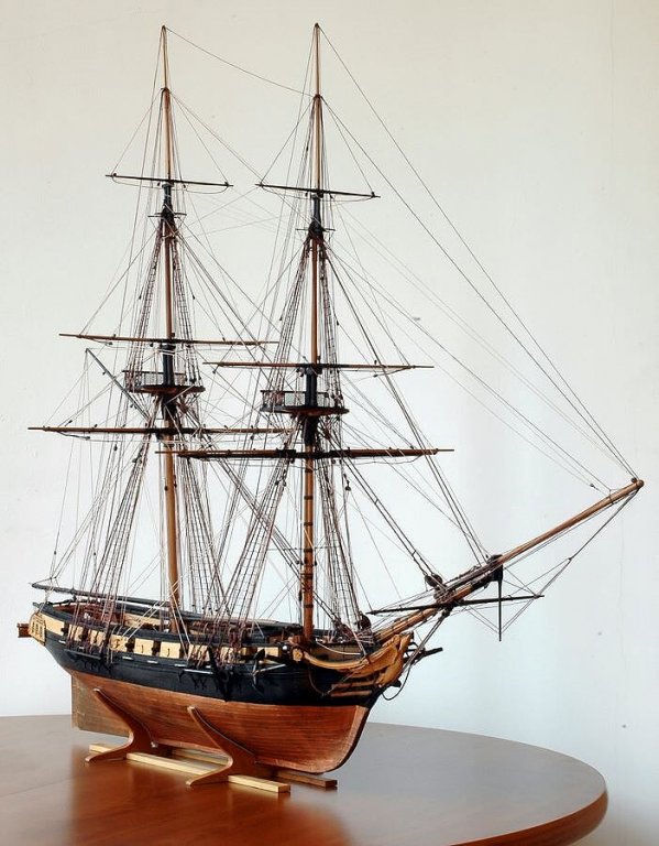
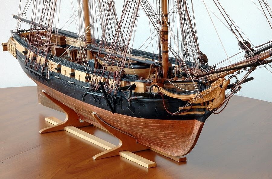
I'm building the static model of a Spanish 1st rate vessel, the Santisima Trinidad. It's not a scratch built model but it is built with materials and instructions shipped monthly with a periodic magazine from De Agostini, an Italian press editor.
Currently there are several models that are sold by De Agostini in this way. In addition to the Santisima Trinidad, there is another model of a spanish vessel, San Felipe, the Japanese Battleship Yamato and the Luis Vitton Cup Luna Rossa.
This is only an initial message in order to introduce myself and what I want to do in this forum.
My nick name is Jack.Aubrey. I selected this nickname because Jack is one of the two protagonists of the historic novel series from Patrick O'Brian. Maybe he's more known from the movie "Master and Commander". I have read all his books of this series translated in Italian.
I'm italian. I'm 57 years old and I was a ship modeler when I was young.
Six months ago I retired form active work and I have resumed my old hobby.
When I was young I built some models. They are all about +/-35 years old. If you are interested to see some photos of them please have a look to the forum titled "The 74-gun ship San Juan Nepomuceno" on page 1. The San Juan is another model that I'm currently building.
Regards. Jack
-
The real challenge will be to sand the bulkheads, flush with the added wood. This should be very strong, for sure.
Hi Yves,
In theory you are right, sanding manually the toptimbers of the bulkheads may be a nightmare, but there are the power tools . . the oubiquitous mini drill with a drum sander or a cutting disk or the belt sander and also the delta sander . . all of them may be useful, provided you are patient and careful to manage these tools to keep safe your model and your hands . .
Regards, Jack.
-
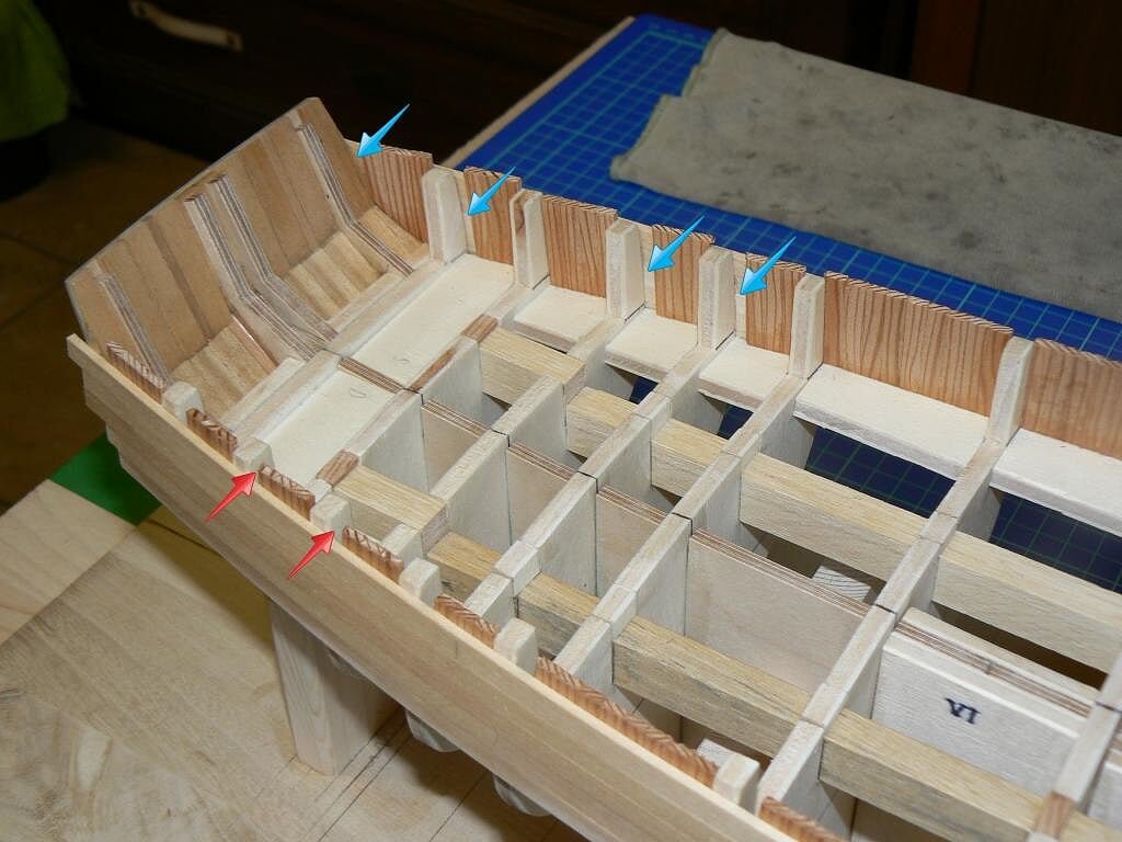
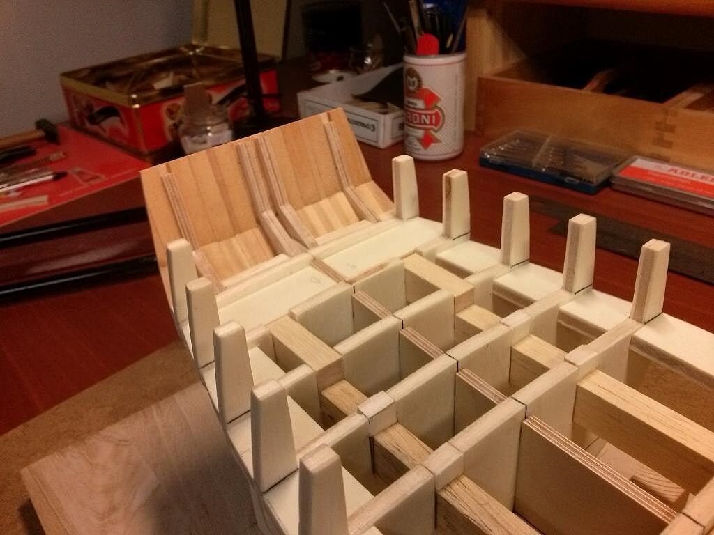
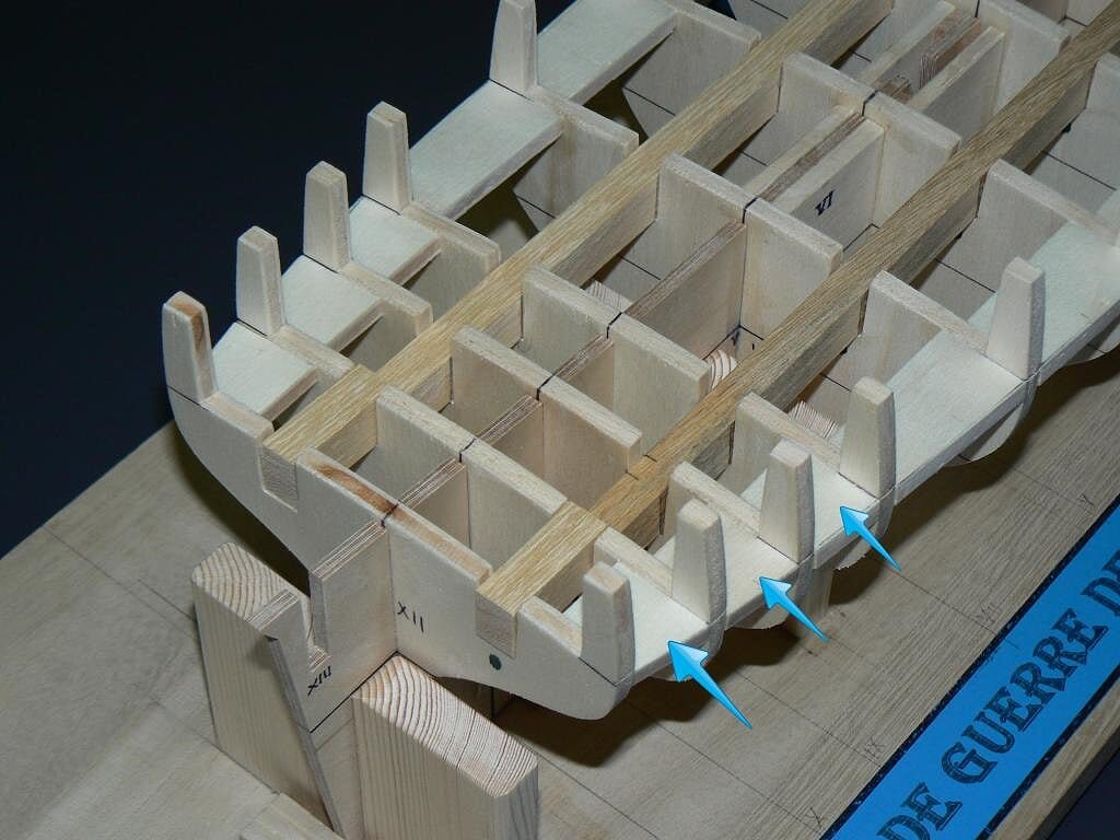
As promised I try to explain more in detail the process of building the bulwarks.
Before continuing with the application of the planking downwards, I decided to finish all the area that now is already planked. This part of the hull, being a brick a single decked ship, is the area where the gun-ports will be opened, and inside, the deck will contain all the superstructures of the model.
The thickness of the bulwarks, according to ANCRE plans, is reported to be 6.5-7 mm, and then I found myself faced with two possible assembling solutions.
Given that a second planking is planned, made with veneer of a wood not yet decided, with thickness of 0.5mm I proceed to describe the two options:1) sand and level the available toptimbers, already part of the bulkheads, to a thickness let's say of 3 mm, and then apply the internal planking based on strips of 1.5 mm thick; the result will be 2 (external planking) + 3 (toptimbers) + 1.5 (internal planking) + 0.5 (second planking of veneer), with a total thickness of 7 mm. During the opening of the gun-ports I should expect that there will be a vacuum inside, to hide properly;
or
2) a: fill with strips with thickness of 2 mm the internal spaces between the toptimbers; these strips, to strengthen the structure, should be placed vertically; b: then repeat with other strips of the same thickness but placed in a horizontal manner; in this way we have reached a total thickness of 6 mm of a virtually all solid wood, a real "sandwich"; c: at this point level the toptimbers properly and d: by applying the veneer (second planking), both externally and internally, reach the desired thickness of 7 mm. The opening of the gun-ports will always find solid wood.
Personally, I chose the second solution for two reasons:
1) even if it may appear more complex it is much easier to achieve in practice, you just need a bit of patience due to the fact you are managing many small pieces of wood;
2) the structure thus obtained is extremely sturdy, virtually indestructible . . and for a fanatic like me this robustness is crucial.And the images that follow, which have more details of those I proposed yesterday, show what I'm doing.
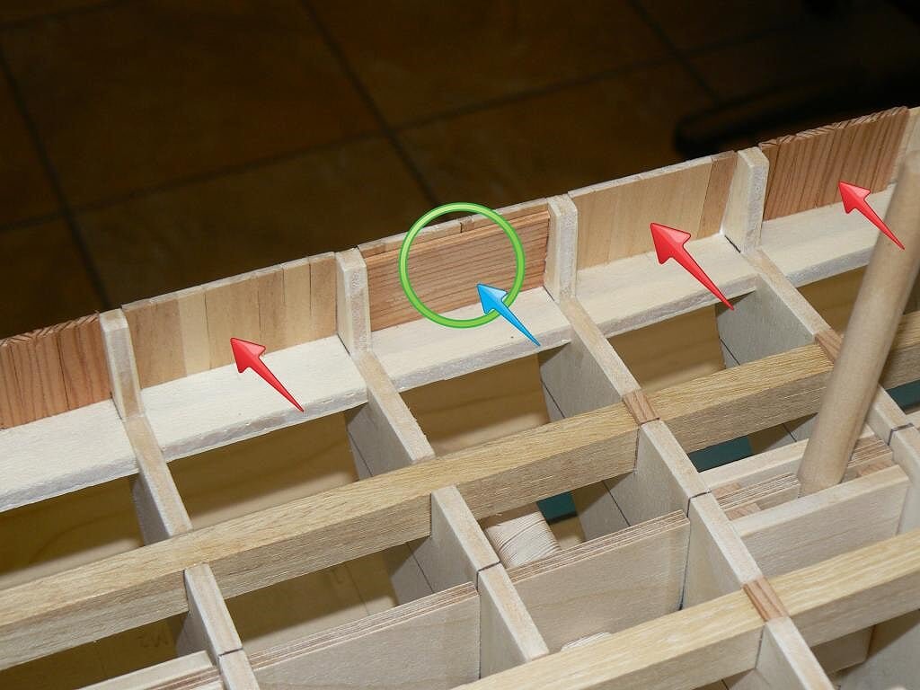
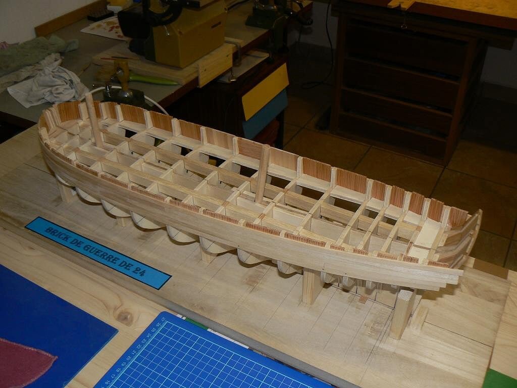
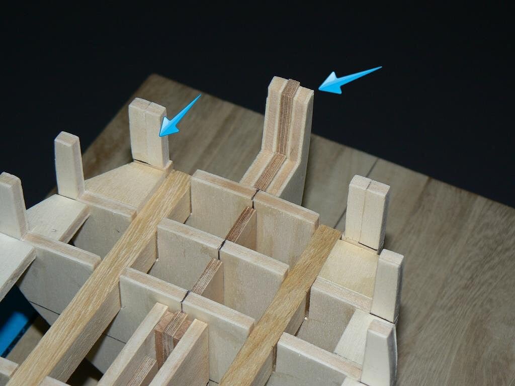
The first two figures show the first inner layer of strips placed vertically, fore and aft. The wood used was got from my stock of strips and I think they are larch, wood good and hard enough but that is not usable for finishing because the grain is too exaggerated. The arrows show the small areas still to be finished that need to be filled with custom pieces of wood, task I'll perform at the first opportunity. It's also important to fill these small gaps to ensure robustness and to avoid finding these gaps when you open the gun-ports.As to complete the outer planking of the bulwarks still lacks a last plank of 4 x 2 on top, these vertical slats are high enough to apply this last missing strip, with a small surplus which will be leveled at the end. The installation of this last plank will be much simplified as will rest in every point on the rear structure.
01 Brick%20by%20JackAubrey/a9b9edb4-da6d-430c-ae5f-5622c2d56ab7_zps9bc6ae7d.jpg
02 Brick%20by%20JackAubrey/73ce6050-5f8e-4152-aa22-fffd8f9ec264_zps909041a1.jpg
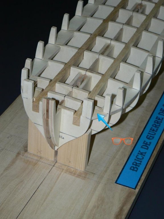
In the image below I propose an anticipation of the next step, shown here by a green circle: the same strips are now installed as an additional layer in a horizontal manner. And it is at this point that I can reach the planned 6 mm thick solid wood . .
03 Brick%20by%20JackAubrey/01bb19c9-4368-40fb-b22a-06a9794fac09_zps87a88d0b.jpg
I hope to have given you an idea of the kind of work is waiting me in the next few days and what you will read accordingly in the next few posts related to this model. The opening of the gun-ports will be done later, after I'll finish to plank the hull and the deck.
To meet next time, Jack.Aubrey.
04 Brick%20by%20JackAubrey/P1100044_zps91f9e4e1.jpg
-
Saturday, October 18th, 2014
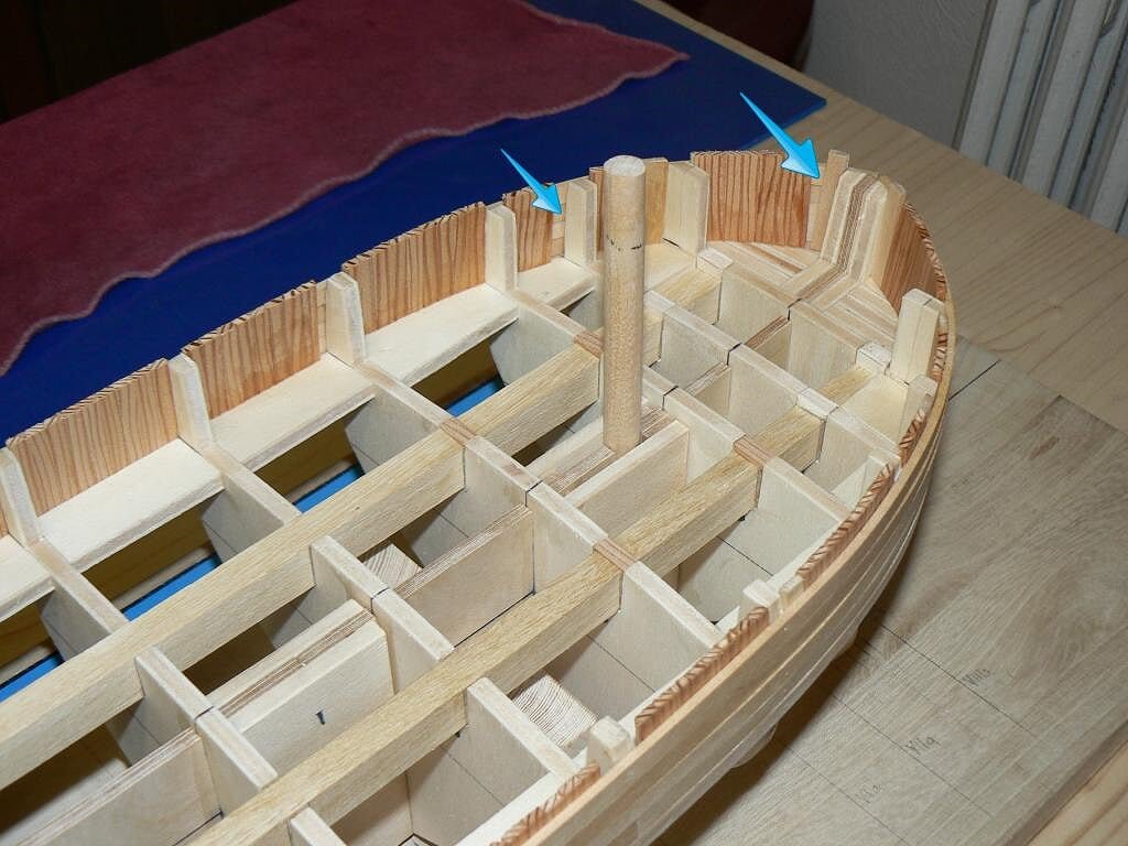
In these days since my previous post where I showed the state of my model, I finished to install the upper planks in the bow area. Here, with respect to the stern, there was an additional difficulty due to the need to properly fold the strips.
My method, now standard for me, uses a metal can, fixed on a stable base, with a small candle inside that warms the upper surface of the can. I place the wood strip, previously put to soak in water for some time, and I model it to the desired shape. For me now it's child's play and the curves come very natural.As always, I emphasize the fact that the strips (6 x 2 mm), in addition to being glued to the bulkheads, are also glued together so that they constitute a very solid and robust surface. As always I uses vinyl glue and, where necessary, clamps to hold or brass nails (not completely hammered, so that I can easily remove them when the glue is dry).
At this point, the external bulwarks size is pretty much over, missing only a final "on top" strip of 4 x 2 mm which I will apply later.
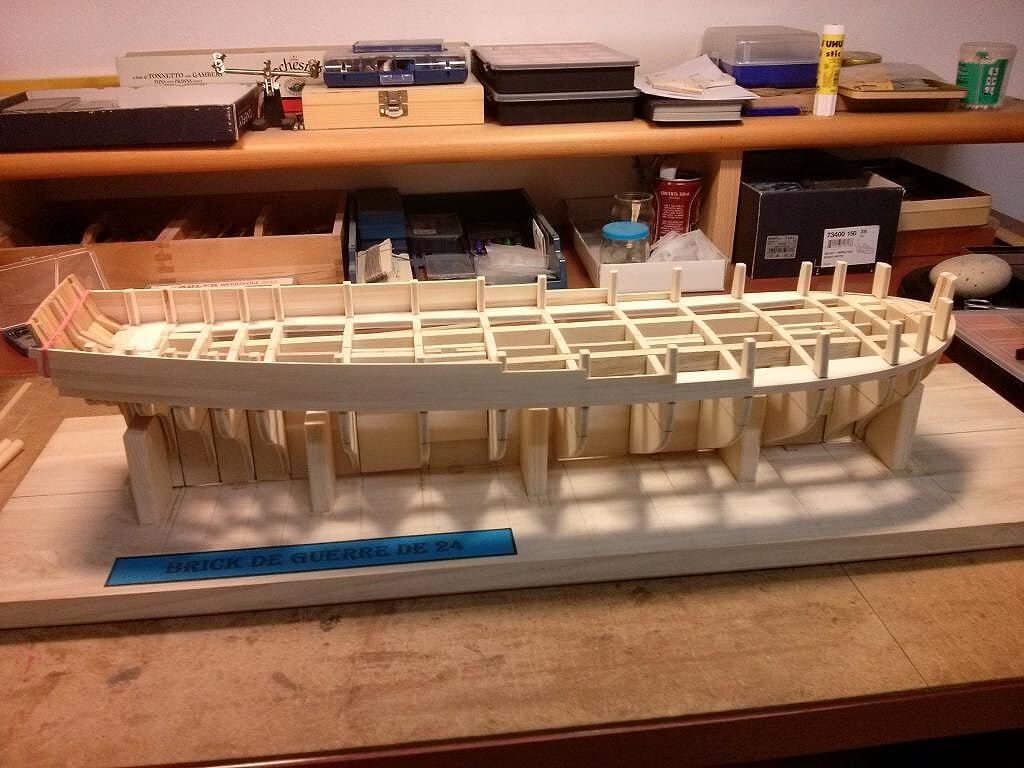
Finally today I focused my work on the bulwarks from the inside. In the following photos you can look at the work done inside, where I fixed generic pieces of strips vertically. The thickness of these strips is 2 mm.
The combination of the horizontal outer planking and the vertical internal planking has now a depth of 4 mm and the whole has a extraordinary rigidity and robustness.But let the pictures speak . .
Three-quarters of the bow on the right side . .01 Brick%20by%20JackAubrey/P1100041_zpsbe8f420f.jpg
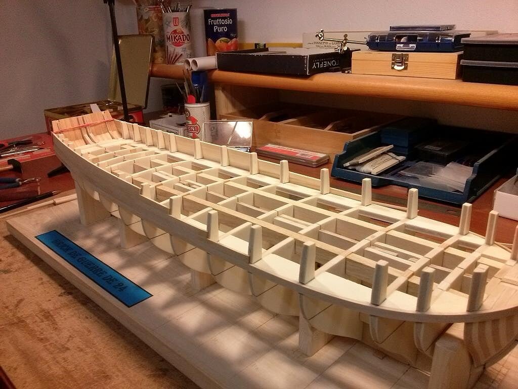
Again three-quarters of the bow of the left side . .
02 Brick%20by%20JackAubrey/P1100043_zps074deab0.jpg
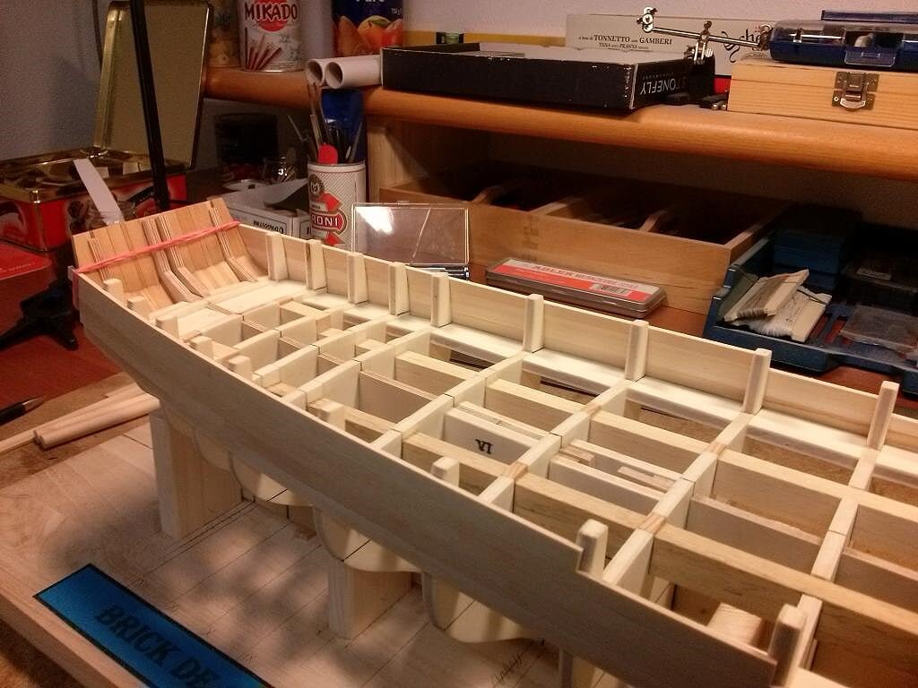
Other views from different viewpoints . .
03 Brick%20by%20JackAubrey/P1100036_zpse95a5ac2.jpg
04 Brick%20by%20JackAubrey/P1100042_zps0722b0a6.jpg
05 Brick%20by%20JackAubrey/P1100040_zps857068ca.jpg
In the next message I will deepen the internal construction of the bulwarks to see where I'm going. .
Friendliness. . Jack.Aubrey.
-
Wednesday, October 15th, 2014
Today I started to apply the first planks. .
These are strips of lime wood, very beautiful, size 6 x 2 mm, purchased at a model hobby shop in Milan hinterland.The first strip, in the photos the lower one, is in one piece and has been installed according to the line references of the deck, references which were previously marked on the bulkheads with a small incision on the outside and passed through with a pencil. With this one piece plank I secured a very accurate alignment and natural sheer.
Then I started to apply shorter planks concentrated in the area from amidships to the stern to rise, in order to properly cover the deck walls.
Next activity to reach the same situation from amidships to the bow. I hope tomorrow. . friendliness, Jack.Aubrey01 Brick%20by%20JackAubrey/CAM00352_zps7734b1f0.jpg
02 Brick%20by%20JackAubrey/CAM00353_zpsa31b4e8c.jpg
03 Brick%20by%20JackAubrey/CAM00354_zps5195574f.jpg
- mtaylor, ChrisLBren, harvey1847 and 5 others
-
 8
8
-
Monday, October 13th, 2014
Today I overcame my reluctance to make dust and in the afternoon I set a good pace to shape the bow and adequately prepare the bulkheads with the "famous" bevel angle.
Below you can see the bow area, where there was to sand more with power and manual tools than in other areas of the hull:01 Brick%20by%20JackAubrey/CAM00347_zpsf4527c5b.jpg
But even in the stern there was enough work to do, in particular for shaping appropriately the transom in order to make possible to glue the last piece of the planking. Here a view of the internal side:
02 Brick%20by%20JackAubrey/CAM00348_zpsd8c6be91.jpg
While here below I propose a view of the transom from the outside. As you can see the stern looks more like a stern than before I worked on it. In due time, I will also shape the top side, the horizontal one, of the same.
03 Brick%20by%20JackAubrey/CAM00349_zpsccdb1613.jpg
However also the entire hull, limited for now only to the part above the waterline, has been sanded properly. In fact, the next step will be the installation of the planking at the top of the hull, in particular on the external and internal sides above the main deck. The lower hull will be planked in a second time, when the top is complete and will be possible to capsize the hull without risks:
04 Brick%20by%20JackAubrey/CAM00351_zps0760046a.jpg
To do this work, today I used a new entry: the belt sander BS/E (or BSL 220/E) from Proxxon. A couple of tests on pieces of wood to waste just to make some experience with the tool and then I started . . it works pretty well although quite noisy and tending to heat up quite a bit after you use it for some time.
Brick%20de%2024%20Plans/BSL220E_zps8f1f50f3.jpg

Kind regards, Jack.Aubrey.
-
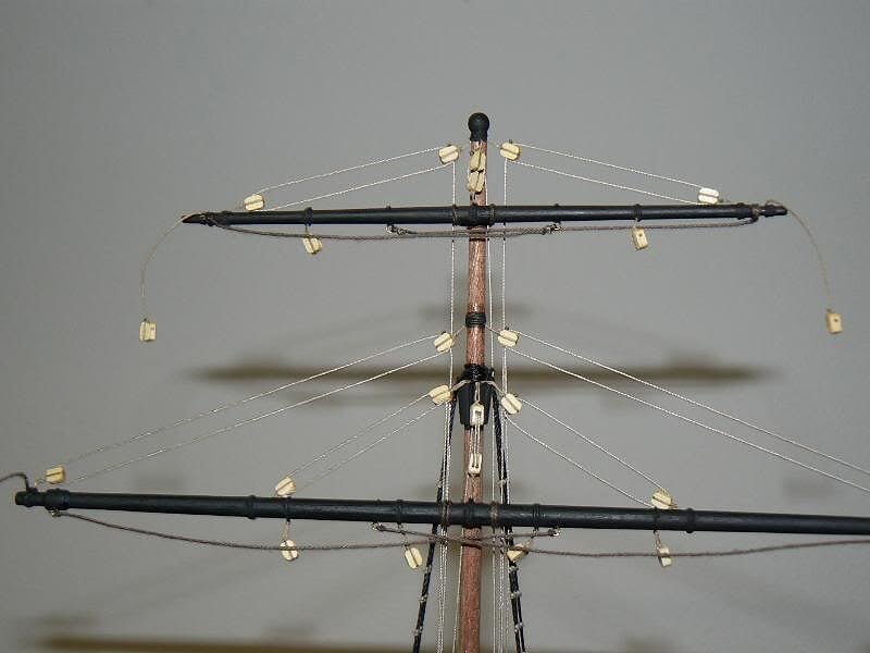
Friday, August 26th, 2011 - Yards installation
Today and yesterday I dedicated myself to the installation of the masts and yards to set up some running rigging. I had to spend quite a bit of time to figure out all the way around, but once I made the first chapter and test on the smaller yard, the work proceeded quite well, so that today I can show you all the yards installed.
The first two yards from the top of the main mast (main royal yard and main topgallant yard):
01 Cross%20Section%20Santisima%20Trinidad/P1070769.jpg
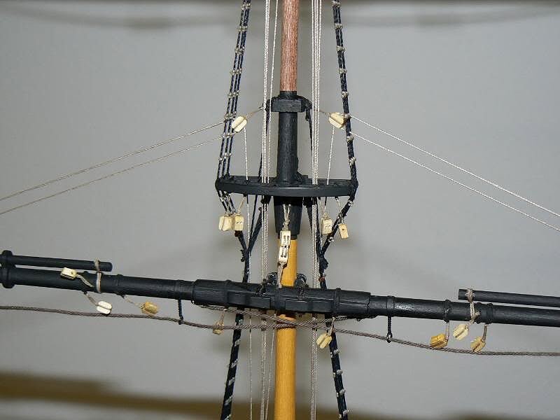
The main lower topsail yard:
02 Cross%20Section%20Santisima%20Trinidad/P1070768.jpg
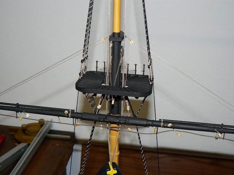
The main yard:
03 Cross%20Section%20Santisima%20Trinidad/P1070766.jpg
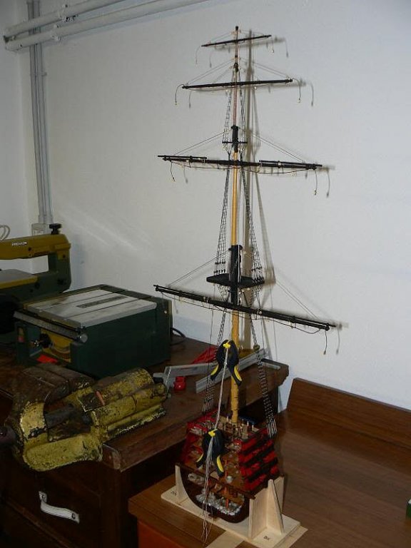
As you can see looking at the clamps, visible close to the hull in the picture below, all operations have not yet been laid down in their location. The clamps hold them together a little strained, nothing more.
I intend to set only the maneuvers at the right time because otherwise an error may become unrecoverable. I am sure you will understand the reason for some misalignment between the yards and the tree: they are almost exclusively due to the fact that the running rigging is still loose.04 Cross%20Section%20Santisima%20Trinidad/P1070771.jpg
Finally I need to fully decipher the pattern of the mounting points of the rigging, I think that there are some errors in the drawings (to be verified). For example, in the two pinrails at the base of the mast, there are a total of eight pins while the cables that you will have to end there seem to be many more. . we will see.
In spite it is a very simplified scheme it is still relatively complex, to be studied carefully. Now I have to think about the fitting of the sails, which seems to be the next step. Their assembly is yet to be studied and understood. Matter for the next few days.
Greetings to all, Jack.Aubrey
- foxy, GuntherMT, CaptainSteve and 3 others
-
6
-
Continuation of the previous message . . full view images.
04 Brick%20by%20JackAubrey/P1100031_zps5bc7f705.jpg
05 Brick%20by%20JackAubrey/P1100030_zpsf148ad2e.jpg
06 Brick%20by%20JackAubrey/P1100029_zps3882f7df.jpg
Regards, Jack.Aubrey
- yvesvidal, hexnut, harvey1847 and 2 others
-
5
-
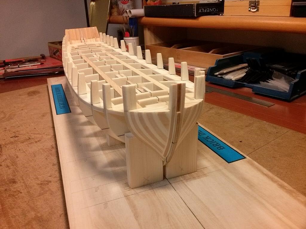
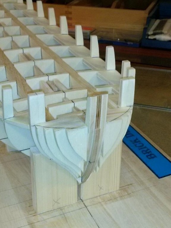
Friday, October 3, 2014 - Structure of the sternI put aside for the moment the figurehead "dilemma", although the topic remains open, to move on.
It's been several days since I posted new pictures of the state of the shipyard and what I am about to show may appear a very small thing for those who have not experienced the problems I lived.
In fact I could not spend the time on the model as I wanted because some commitments did not allow me, but apart from this detail, in fact, after a first attempt that did not achieved the results I expected, I had to disassemble what was wrongly done and start over with some variations. The explanation is all here.
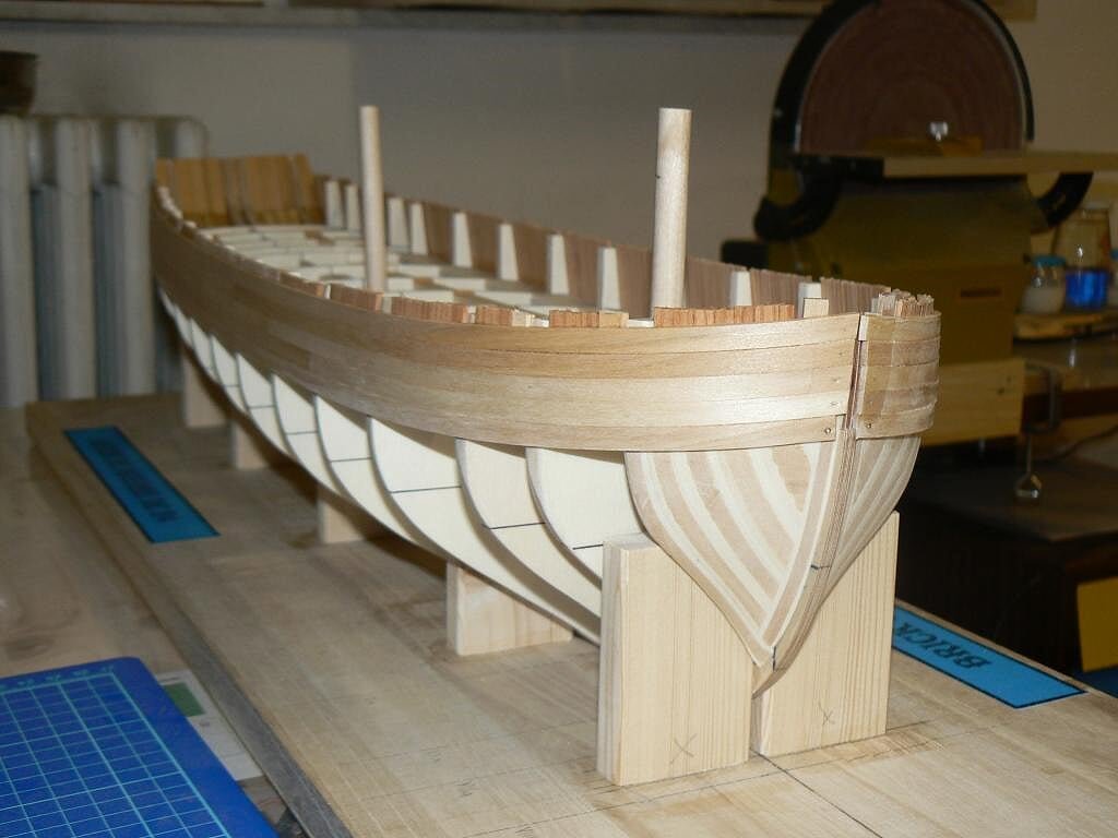
In the first picture you can see the exterior of the stern, which is slightly curved and "square" shaped, shape that is to be considered temporary. In fact, the next step will be to cut out the contours to the shape of the plans. At the time the sizes are quite generous. But from the outside, you don't understand how this structure is built . .
01 Brick%20by%20JackAubrey/P1100034_zps83e0931a.jpg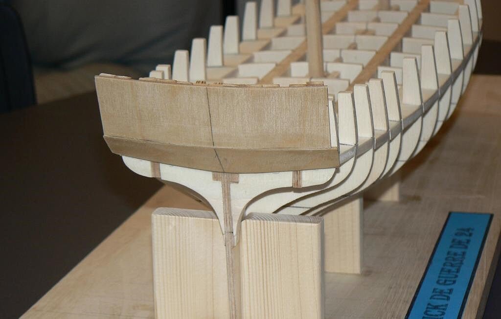
Instead, the view from inside should serve to show how everything is set up.
In fact we can identify three elements that compose it and which, together, provide the thickness and adequate strength until the planks will not be applied:
- Four shaped supports which are fixed to the last bulkhead and provide the base for the other two elements. They are made with special plywood because I felt very sturdy and therefore unsuitable to use the classic poplar plywood. However, it is the same material used for the keel.
- The outer part consisting of two shaped plywood pieces of 1,5mm. applied externally to the previous element. The top one is simply rectangular, the lower one has a shape that I had to get empirically by testing first with cardboards until I identified the right one and then copy it on to the plywood.
- Once the second element was fixed the next day I proceeded to stiffen the inside using lime 8x2mm strip glued properly. Note the need to cut with a given angle the side that met the internal angle and the bulkhead. To do this was very useful the power sander that I bought from Proxxon time ago.
Now that everything is perfectly dry it looks like a very strong structure able to deal with the stress of the next processing.
02 Brick%20by%20JackAubrey/P1100033_zps8b1cb266.jpg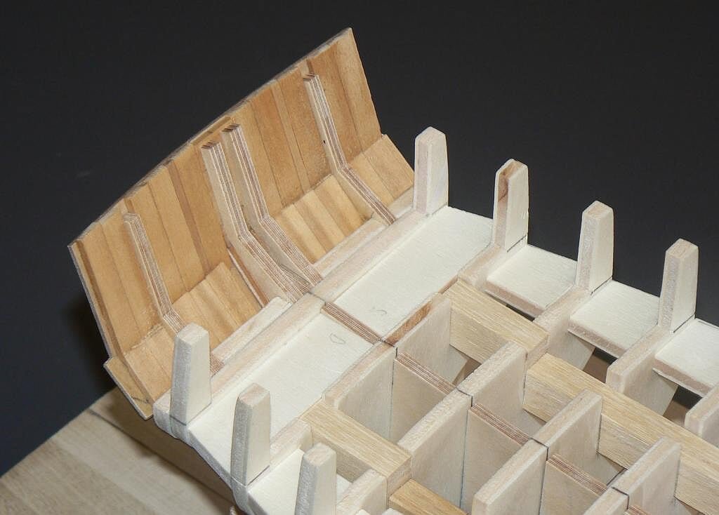
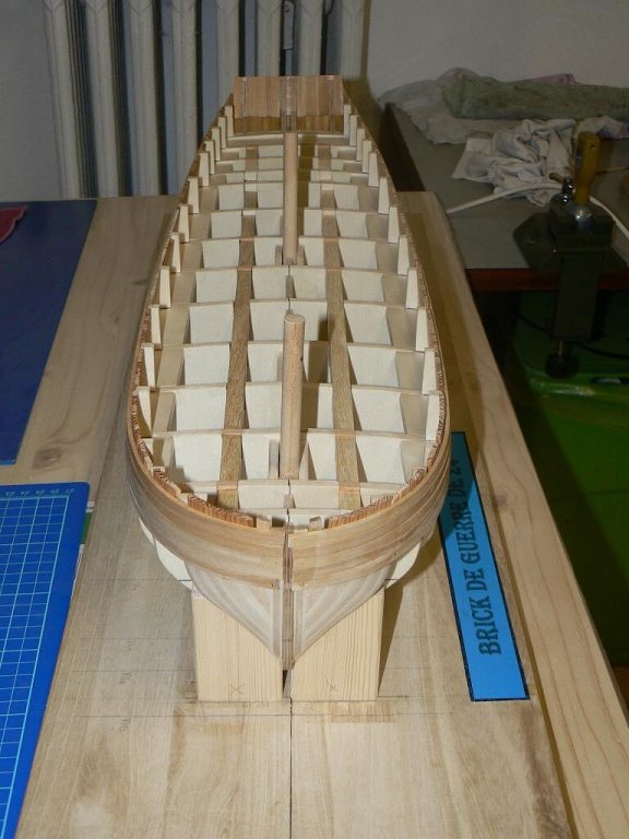
Finally, an overview of the whole skeleton of the hull.
03 Brick%20by%20JackAubrey/P1100032_zps1be31e11.jpg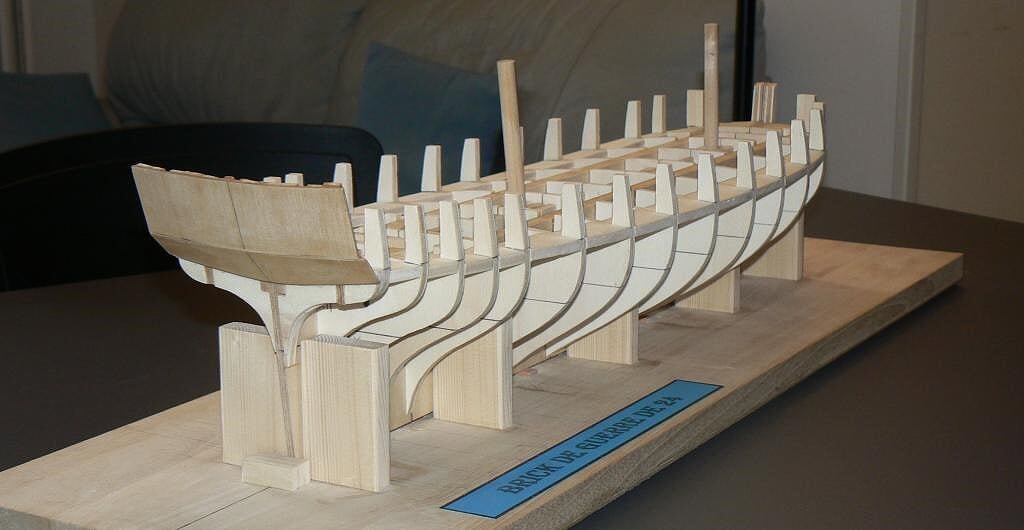
To be continued . . Regards, Jack. -
Voltigeur can be loosely translated to "jumper".
This refers to Napoleon's elite light infantry skirmishers, who originally were supposed to jump onto the back of a cavalry horse and ride behind the cavalryman to the "trouble spot".
"Les compagnies de voltigeurs de l'infanterie de ligne ont été crées en 1805. En théorie, le voltigeur est un soldat capable de sauter en croupe d'un cavalier afin d'augmenter sa mobilité."
Then they would jump off and fight on foot.
The transportation method didn't prove to be practical, but the Voltigeurs saw much action, notably in the Iberian peninsula fighting against British light infantry and rifle companies.
They did have distinctive uniforms that might make an interesting figurehead...
Hi hexnut, provided it is the right character assigned as name to that brick, your image should be interesting to reproduce as figurehead. Thanks a lot, also for the piece of history till now unknown to me. Jack.
-
http://5500.forumactif.org/t1814p80-le-curieux-au-1-160-par-r-simon
Follow this link. It's a building log of Mr.Richard Simon, on the Delacroix's forum.
Yes, it's Le Curieux, I didn't mention it because I thought was Le Cygne.
The modelers mentions a plan of Le Courieux, but its incomplete, and the figurehead is missing. Anyway, he managed to find out how was it, and he built it.
Greetings.
Giorgio.
Hi Giorgio, I already know this model from this article. Here is the full article: 59-2 NRJ French War Brig article.pdf
Thanks anyway, Jack.
-
Thanks to Giorgio (GioMun) because in its message I had the possibility to identify exactly the authors of the two models I presented in this topic. The Authors (with the A in capital letters) are:
for Le Cyclope, Bernard Frölich
for Le Cygne, Jean-Claude Buchaillard
And thanks to all the other users for their contribution with their opinions . .
I'm seriously considering a fourth alternative for the figurehead, I'll explain better.
I wrote that it's my intention to build a brick captured by the RN and I have selected 9 potential candidate. The nine brick to which I refer are those listed below. I tried their translation into Italian and I got interesting references. The original French name represents, if I understand correctly, birds and in some cases mythological characters.
Curieux >>> Curious (??)
Phaeton >>> Phaeton (mythological) but also a bird
Voltigeur >>> Acrobat
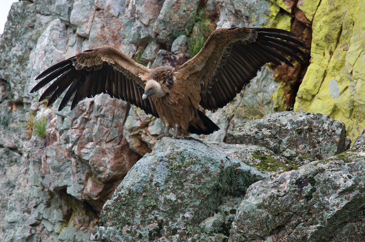
Griffon >>> Griffin
Basque >>> Basque (??)
Lutin >>> Sprite, elf, goblin
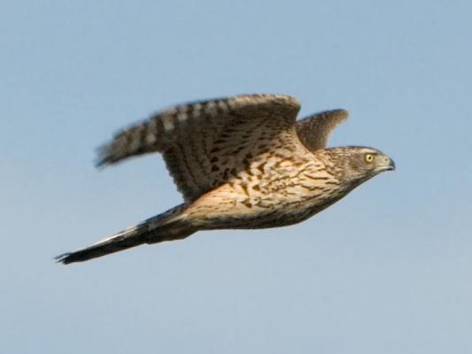
Nisus >>> Nisus character of the Aeneid or Sparrowhawk (Accipiter Nisus), bird of prey
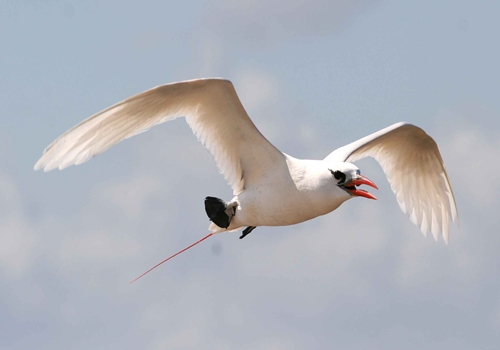
Milan >>> a bird of prey of various species (see Wikipedia)
Colibrì >>> Hummingbird
It's likely or plausible that the "bird" ships had a kind of figurehead like Le Cygne, which represented the bird its name implies, while for others it would be even easier for Phaethon (mith), Nisus (Aeneid) and a little less for Curious, Acrobat and Elf . For Basque just would not idea.
In the ANCRE monograph it seems that this logic may be applied.According to the previous list good candidate names may be: Griffon, Nisus, Milan, Colibrì, Phaeton (bird) and probably also Lutin. Internet provides lot of images usable for these names.
I'll appreciate considerations or comments . .
Here some examples . .
Nisus
Colibrì

Phaeton
Griffon

Milan
- Timmo, Landlubber Mike and mtaylor
-
3
-
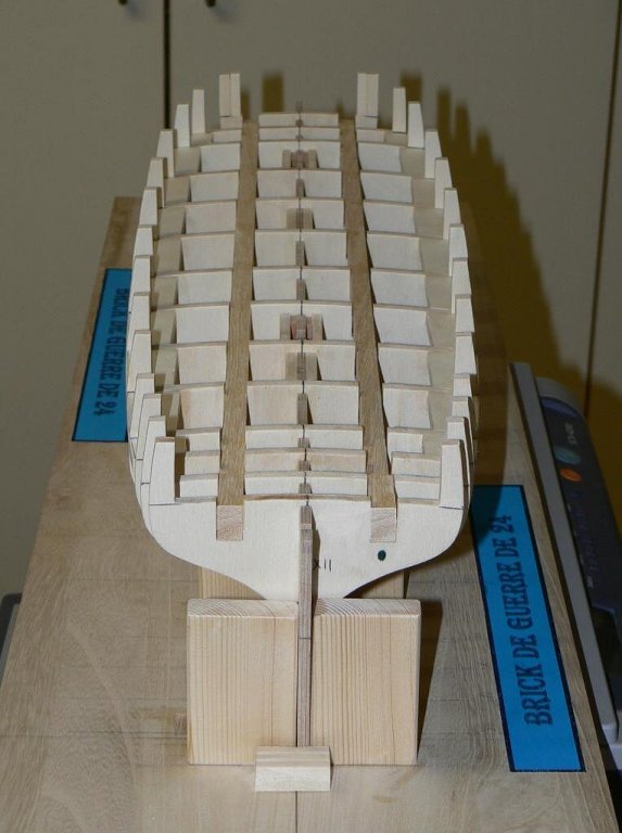
The pictures are great, how are they photographed ? are the shot with a curved white backdrop. or is there some form of masking done?
Hi Michael, the photos I added in that post come directly from the National Maritime Museum. I did not shot them and I have no idea of the technique used to obtain that result . . surely it is fashinating.
Yes indeed, BUT there is something spectacular on shots like "02" and "05" (specially the "scaffolding" holding the ship). I wouldn´t mind to go that way. Specially with that dummy piece of wood which is more evidence on pic "04".
Hi Daniel, thanks for your opinion. However do you feel it should be better to leave unnamed the model in this case ? If I give it a name how can explain is it really ?
Sure Jack - you could approach your model in this fashion to make sure its historically accurate. However in my opinion - the figurehead adds so much to the elegance of the model . .
You are right, there is a fourth solution to my "dilemma": build and install a fictional figurehead. It is what was done by a ship modeller in the article pointed by the link here below:
https://drive.google.com/file/d/0B752g0VVxf2Kc1JjaGJxUVFWWW8/edit?usp=sharing
Does it mean that is a current practice for these situations, provided it is declared ?
-
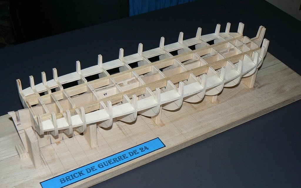
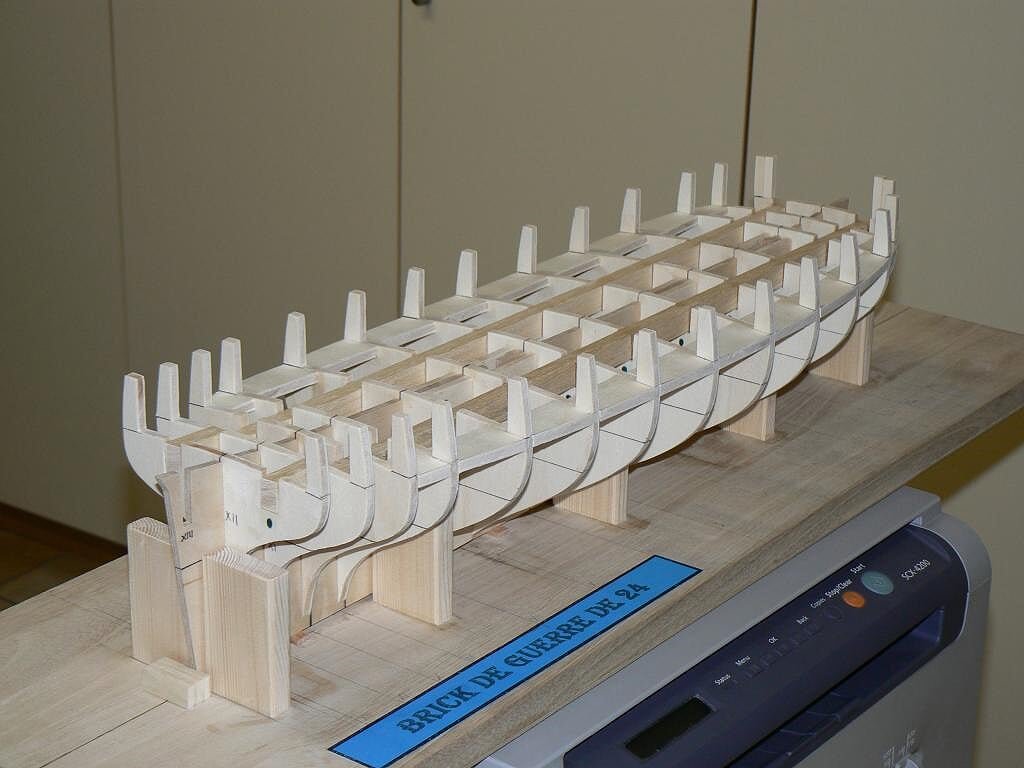
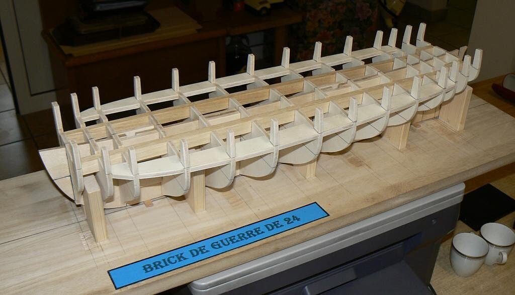
Monday, September 29th, 2014
As I wrote some time ago, at the beginning of this discussion, the model that I am building belongs to a class of brick which has 20, ships designed by Pestel, or 22, if we count the two variants built without changes by Sanè when Pestel fell into disgrace with the major staff of the French Navy.
As I got to write many of these brick were captured by the British and subsequently used into war actions against the French themselves. I have also indicated my intention to build the model of one of the sailing ships belonging to this category and I've identified among these ships nine vessels that, for their acts of war, interested me in a particular way.
Finally, I also wrote that I had not chosen the name of my model, a name that should fall among the nine selected, explaining that I would have to perform more researchs to identify how the figurehead and stern decorations of these models were in the reality.
. . this research (carried out exclusively via the internet) till now did not yet provide results to be able to determine for example, as the figurehead of some of the nine sailing ships concerned was and I'm not confident in succeeding in the future.
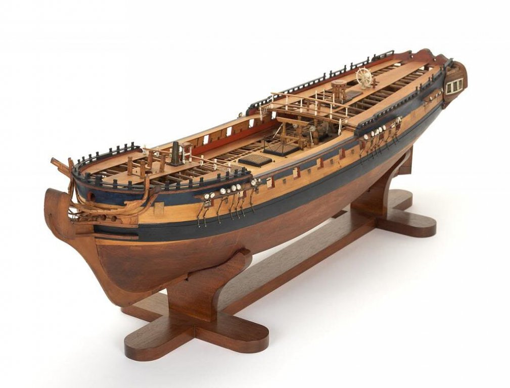
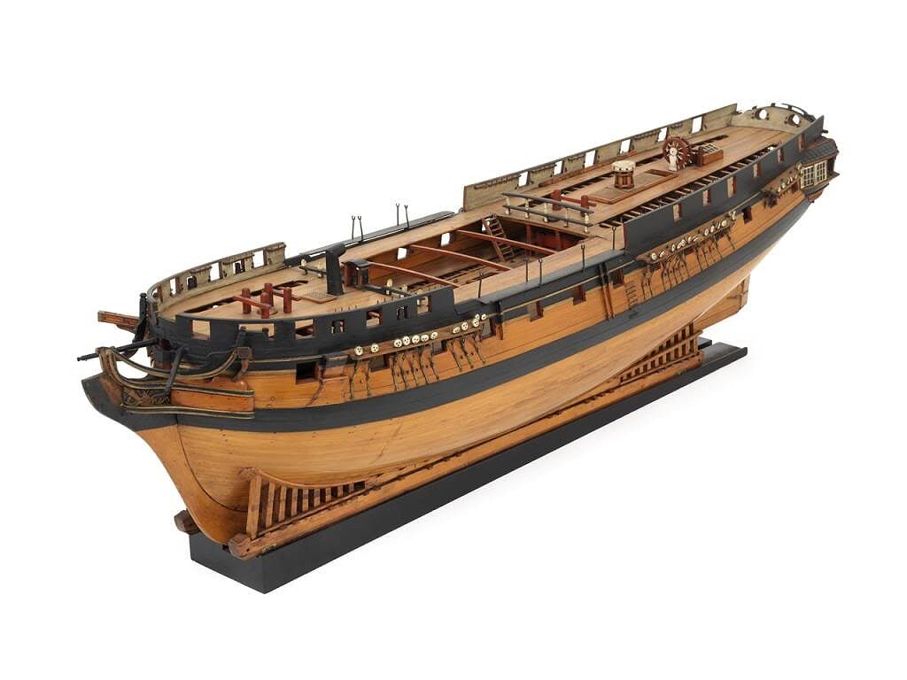
What I were able to establish, by visiting the Maritime Museum in London, was the fact that many of their models have been completed WITHOUT the FIGUREHEAD.
Deepening the topic I noticed that in this case the model does not represent a specific sailing ship, in these images we are speaking about frigates, but represents an hypothetical sailing ship belonging to a particular ship class. In this case, as shown by the images here below, taken from the NMM site, different solutions have been adopted for the figurehead:
a) a flourish dummy
") a block of wood just sketched
a block of wood just sketched
c) a vacancy in place of the figureheadThe three solutions are visible in the screenshots below.
Do you think a similar solution would be eligible for my model in order to have total freedom of choice for the name to be assigned to?
Thanks in advance to those who will take the trouble to answer, Jack.
01 Brick%20de%2024%20Plans/large_zps88b3f2a2.jpg
02 Brick%20de%2024%20Plans/large_zps001cab09.jpg
03 Brick%20de%2024%20Plans/large_zps0b606ee1.jpg
04 Brick%20de%2024%20Plans/large_zpsdc4d6b3b.jpg
05 Brick%20de%2024%20Plans/large1_zps6fa11a99.jpg
-
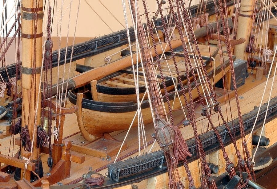
Le Cygne . . Continuation
Here below five other images of the brig "le Cygne".
01 Le%20Cygne/dsc_0611_zpsbbb8f515.jpg
02 Le%20Cygne/dsc_0614_zps85484955.jpg
03 Le%20Cygne/dsc_0615_zpsadfe6f10.jpg
04 Le%20Cygne/dsc_0617_zps2c8301cd.jpg
05 Le%20Cygne/dsc_0619_zps421f9278.jpg
That's all regarding this ship/model. Regards, Jack.Aubrey.
- michael mott, harvey1847, mtaylor and 6 others
-
9
-
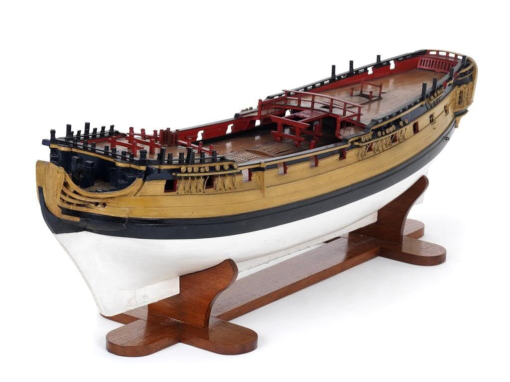
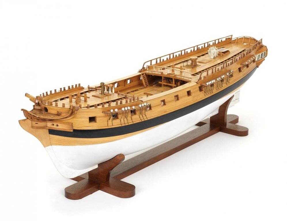
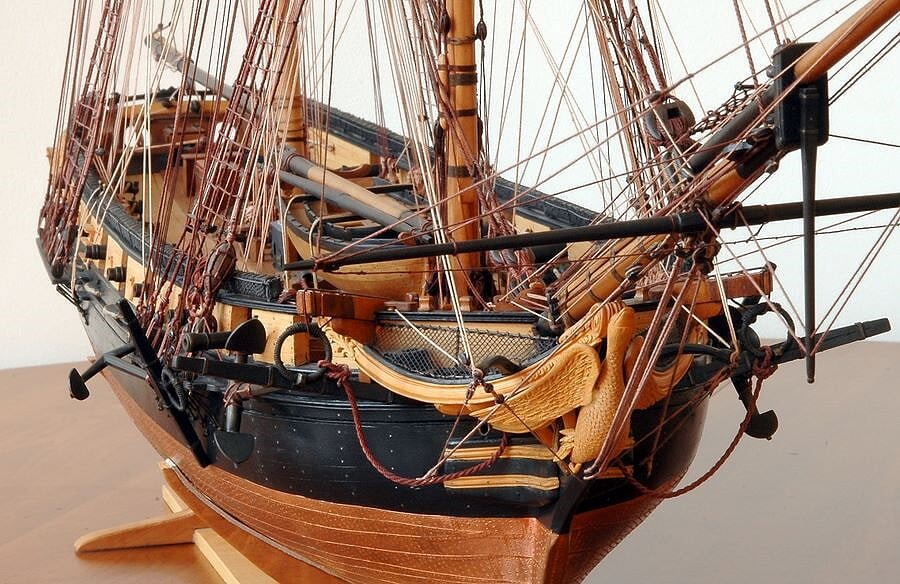
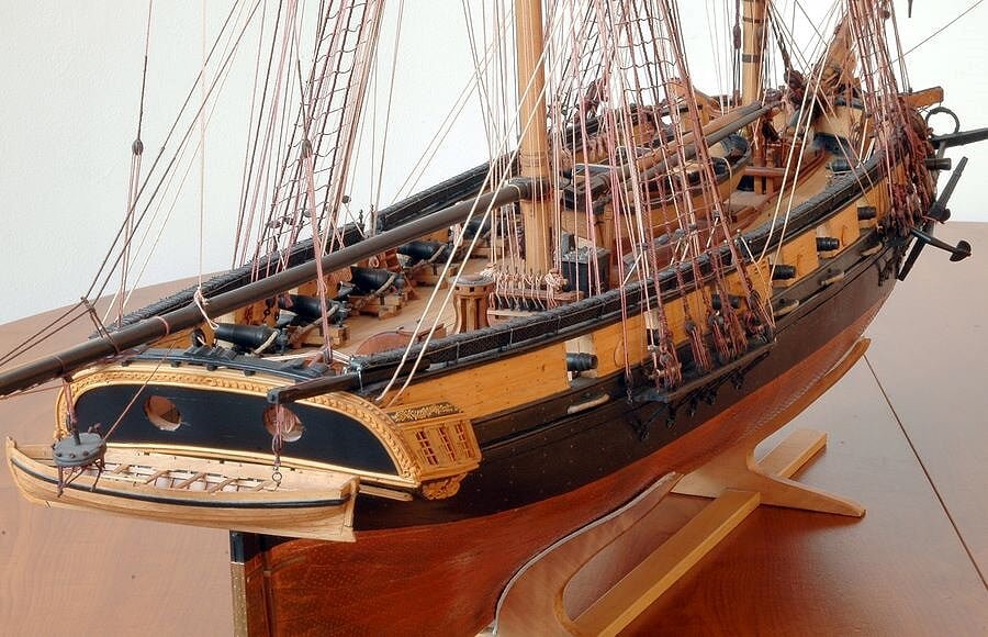
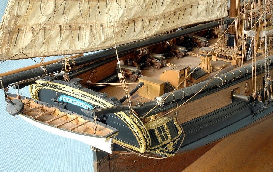
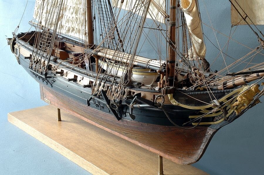
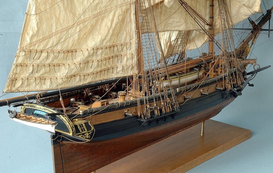
I continue with a series of images of another "brick of 24", belonging to the same class of Le Cyclope.
This model depicts "Le Cygne", the model described in the monograph from ANCRE. Even here I do not know who the model maker is but surely he well knows what to do and how . . and it pays more care in removing dust from the model before taking photos of it.
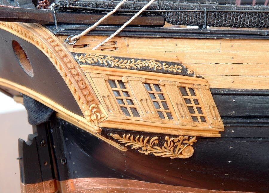
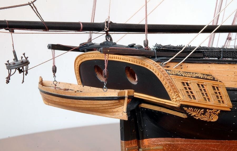
Unlike Le Cyclope, Le Cygne mounted 24pdrs carronades and only two 6pdrs guns at bow. Here are three major differences:
- The figurehead
- The poop lateral "bottles" and the kind of decorations
- The gunports size, that are much larger on Le Cygne than the same of Le Cyclope; I believe that this difference is due to the presence of carronades instead of the guns, to provide a greater visual shooting to carronades.Here below five images of Le Cygne. . to be continued. .
A cordial greeting, Jack.Aubrey
01 Le%20Cygne/dsc_0600_zps7c6c0c60.jpg
02 Le%20Cygne/dsc_0601_zps33d3b303.jpg
03 Le%20Cygne/dsc_0603_zps00d08111.jpg
04 Le%20Cygne/dsc_0607_zps5bfa66b6.jpg
05 Le%20Cygne/dsc_0609_zps558b5763.jpg
- Omega1234, hexnut, Wishmaster and 9 others
-
12
-
On 25/9/2014 at 10:30 AM, Mirabell61 said:
Hi Jack,
I love the combination of the CAD design and the resulting precision scroll saw cutting of the Frames. Very well Fitting Framework, especialy the two Long reinforcement beams under the main deck fit very well.
Also thanks for sharing the and clse up, Pictures of the "Le Cyclope" under sails, thats real eyecandy in every Detail one can see seldom in this quality
Nils
On 25/9/2014 at 4:06 PM, yvesvidal said:Brilliant Jack, excellent ideas and tricks. The picture of the Cyclope, your model and your workshop are glorious.
I love it.
Yves
Thanks, Yves and Nils for your comments, I have greatly appreciated your feedback. I also have to show a second model of this brick/brig class, coming soon . .
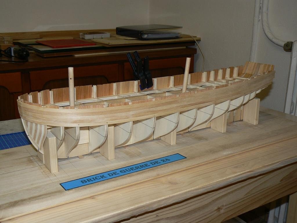
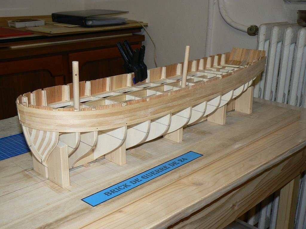
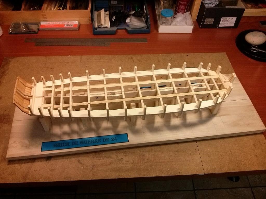
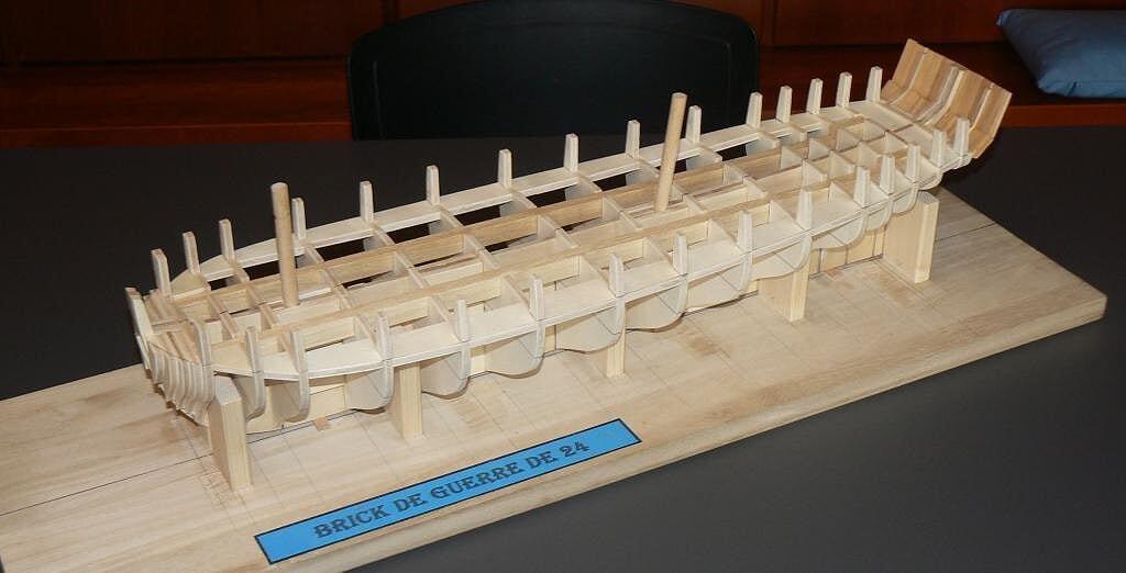
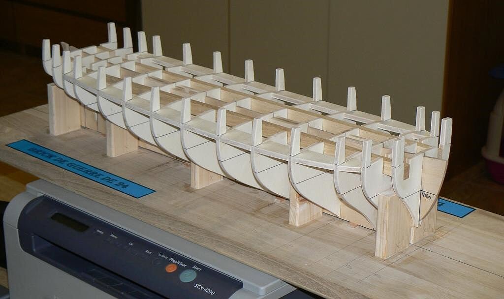
As promised, some overall views of the hull . .
01 Brick%20by%20JackAubrey/P1090995_zpsdf171607.jpg
02 Brick%20by%20JackAubrey/P1090996_zpse1dd41aa.jpg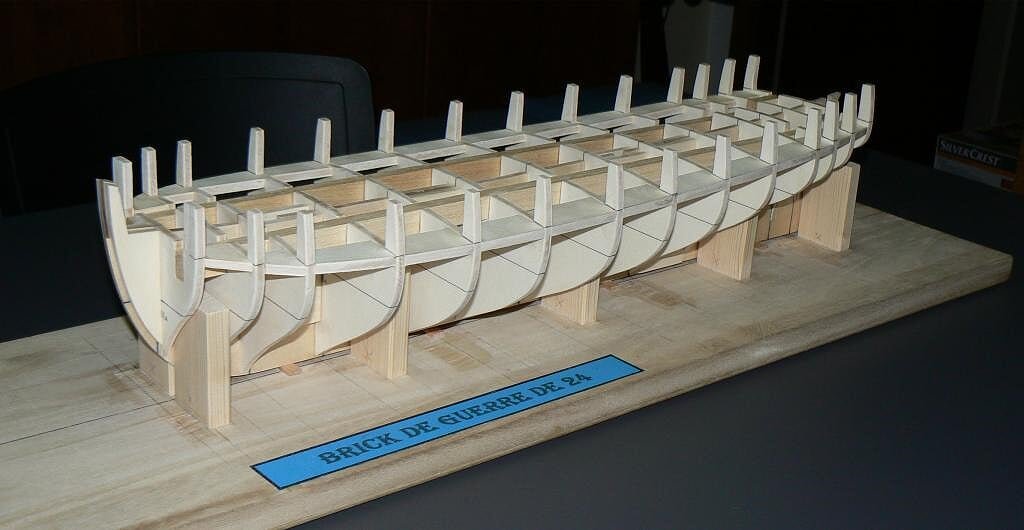
03 Brick%20by%20JackAubrey/P1100002_zpsc51d362f.jpg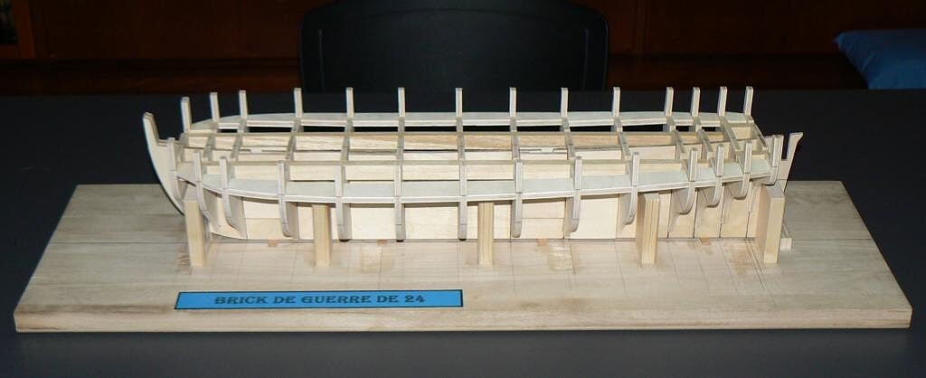
And last but not least the prow completed with the filler blocks, although not yet sanded.
Next step i'll attack the poop. Hoping in a good result.Greetings, Jack.
Brick%20by%20JackAubrey/CAM00340_zps1b9ae24d.jpg
-
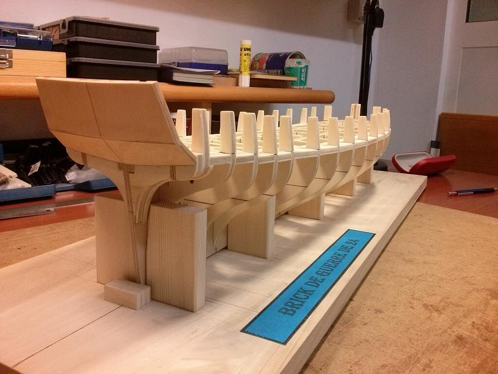
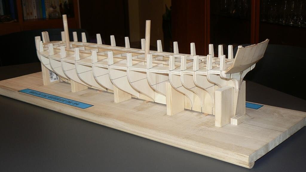
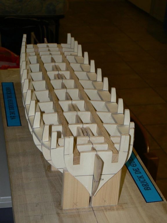
Wednesday, September 24th, 2014
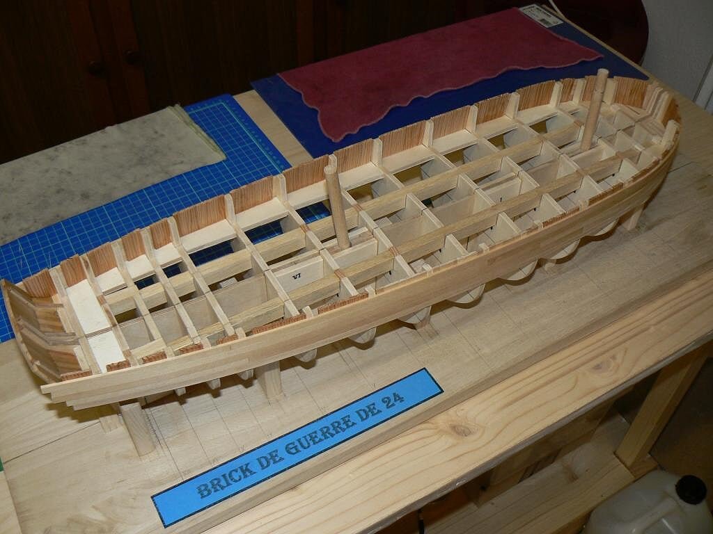
I've completed the installation of the lateral reinforcements at the poop as shown in the following picture . .
01 Brick%20by%20JackAubrey/ca8e53ef-cec4-4139-8c3d-ec00064093fe_zps6a2e4853.jpg
. . and the same was also made at prow. Now all the bulkheads are connected together through these reinforcements and the result is very rigid and strong. This also gives an idea of the sheer of the deck.
02 Brick%20by%20JackAubrey/24aa2826-0150-4342-a0eb-d35d1b59b315_zpscde3a7e9.jpg
Then I worked around the prow, adding the toptimbers to the stem in order to obtain a supporting structure for the planks there.
I've also reinforced the two toptimbers of the first bulkhead by adding a small piece of plywood to enlarge the existing ones. This detail will help when I'll have to bevel this bulkhead.I would like to explain that all the toptimbers will be removed when the planking will be in place . . but this is a matter that I will discuss better in the future, probably now is too early . .
03 Brick%20by%20JackAubrey/0afe5d3a-551b-45c8-9277-6920ab4e91de_zpsa43ac47c.jpg
A detail of the toptimbers at the stem . .04 Brick%20by%20JackAubrey/P1090999_zps868aba59.jpg
In the next message I'll show some overall views, regards, Jack.
-
Le Cyclope . . Continuation
Here follow five additional images of the brick Le Cyclope.
06 Le%20Cyclope/dsc_0392_zps0bc504a8.jpg
07 Le%20Cyclope/dsc_0361_zps23f1d9fc.jpg
08 Le%20Cyclope/dsc_0352_zps1f439ef9.jpg
09 Le%20Cyclope/dsc_0350_zpsf62d22cc.jpg
10 Le%20Cyclope/dsc_0346_zpsb159620d.jpg
That's all for "Le Cyclope". I apologize for the dust . .
Regards, Jack.Aubrey
-
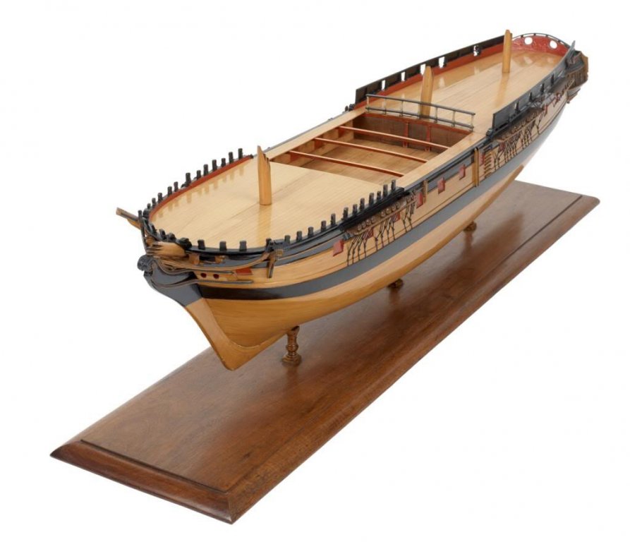
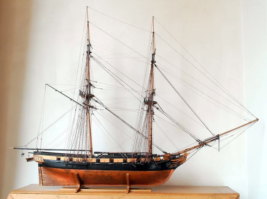
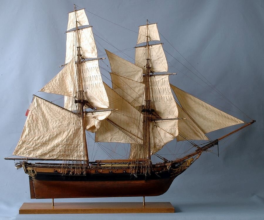
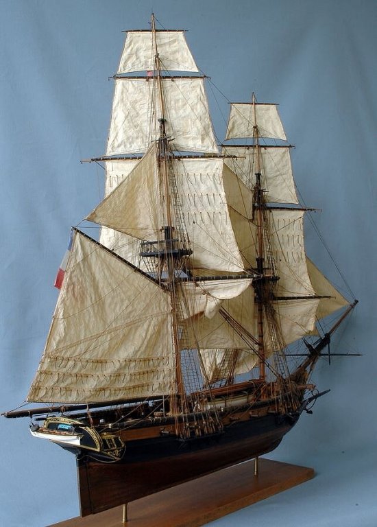
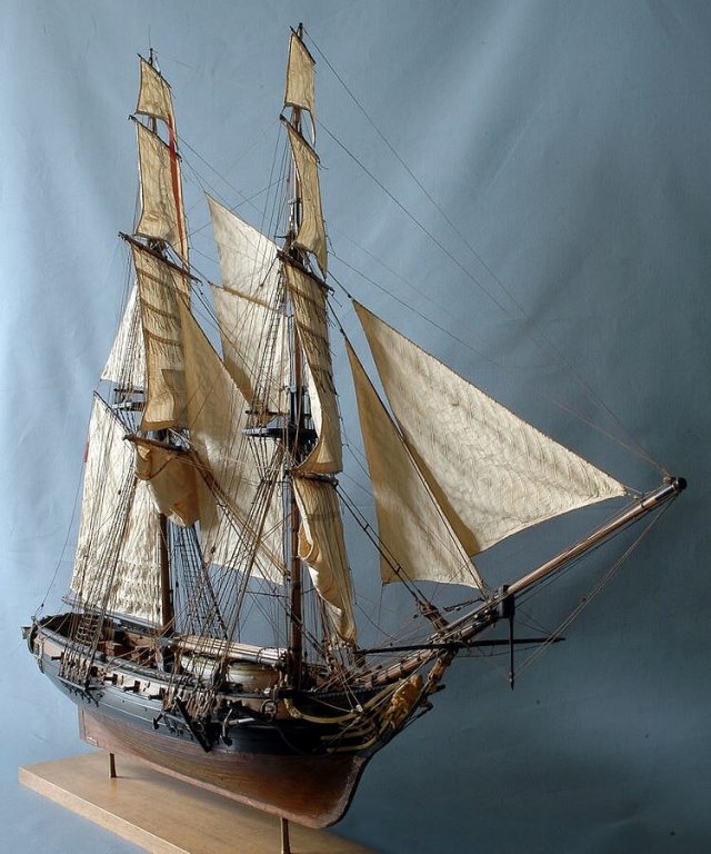
Wednesday, September 24th, 2014 - Some Pictures of "Le Cyclope"
In the absence of new material from my model to show, I start to post some messages in which you can understand what kind of sailing ship I'm building and its appearance once finished.
I'm starting with some pictures of a model of an unknown author, although I think should be B. Frolich, of one of the 22 bricks de 24 designed by Pestel.
It is "Le Cyclope".
Le Cyclope was set up in 1804 and launched in 1810 in Genoa. Armed with sixteen 6pdrs guns she was transferred to Italy in June 1810.Good vision, Jack.Aubrey.
01 Le%20Cyclope/dsc_0336_zps99d9a8ea.jpg
02 Le%20Cyclope/dsc_0338_zpsd16f2304.jpg
03 Le%20Cyclope/dsc_0339_zps3651ac8f.jpg
04 Le%20Cyclope/dsc_0340_zps2e72d043.jpg
05 Le%20Cyclope/dsc_0344_zps699eb6e5.jpg
To be continued . .
- mtaylor, Senior ole salt, WackoWolf and 3 others
-
6
-
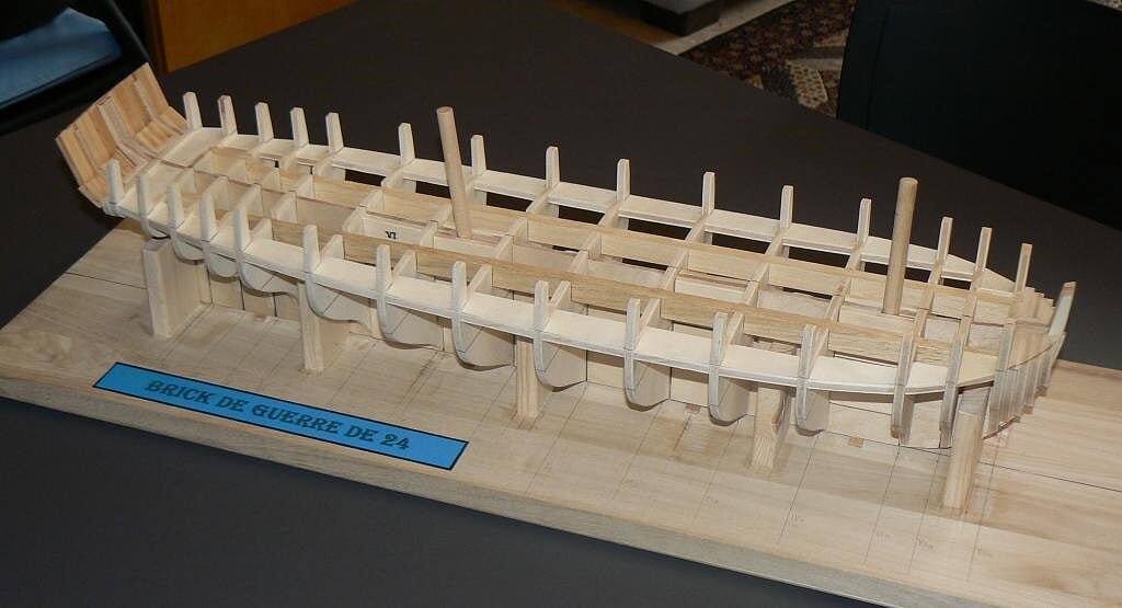
Tuesday, September 23th, 2014
Another small step forward: I've added new lateral reinforcements close to the toptimbers and the deck.
This is probably not strictly necessary to guarantee the hull being crushproof but you must know that I'm obsessed to build strong models. So, this afternoon, I amused myself to reinforce again . .
01 Brick%20de%2024%20Plans/P1090992_zps03457775.jpg
02 Brick%20de%2024%20Plans/P1090994_zps484f9230.jpg
03 Brick%20de%2024%20Plans/P1090989_zpsb02ec9fe.jpg
04 Brick%20de%2024%20Plans/P1090991_zpsedf348aa.jpg
05 Brick%20de%2024%20Plans/P1090993_zps7956957e.jpg
Next it's time to work on the prow and the poop . . It will not be so immediate. Regards, Jack.


Santìsima Trinidad by jack.aubrey - De Agostini - Scale 1:90 - Full Model
in - Kit build logs for subjects built from 1751 - 1800
Posted
Posted: Thu May 03, 2007
A photo of a model of the ship in the 120-gun configuration from a museum in Madrid. Please note the sides painted in red/white.
Second there is a pictorial view of Santisima Trinidad before Trafalgar. It's an oil painting from Geoff Hunt. Geoff is the author of all the covers for the Patrick O'Brian's books about Jack Aubrey and Stephen Maturin novels.