


jack.aubrey
-
Posts
1,268 -
Joined
-
Last visited
Content Type
Profiles
Forums
Gallery
Events
Posts posted by jack.aubrey
-
-
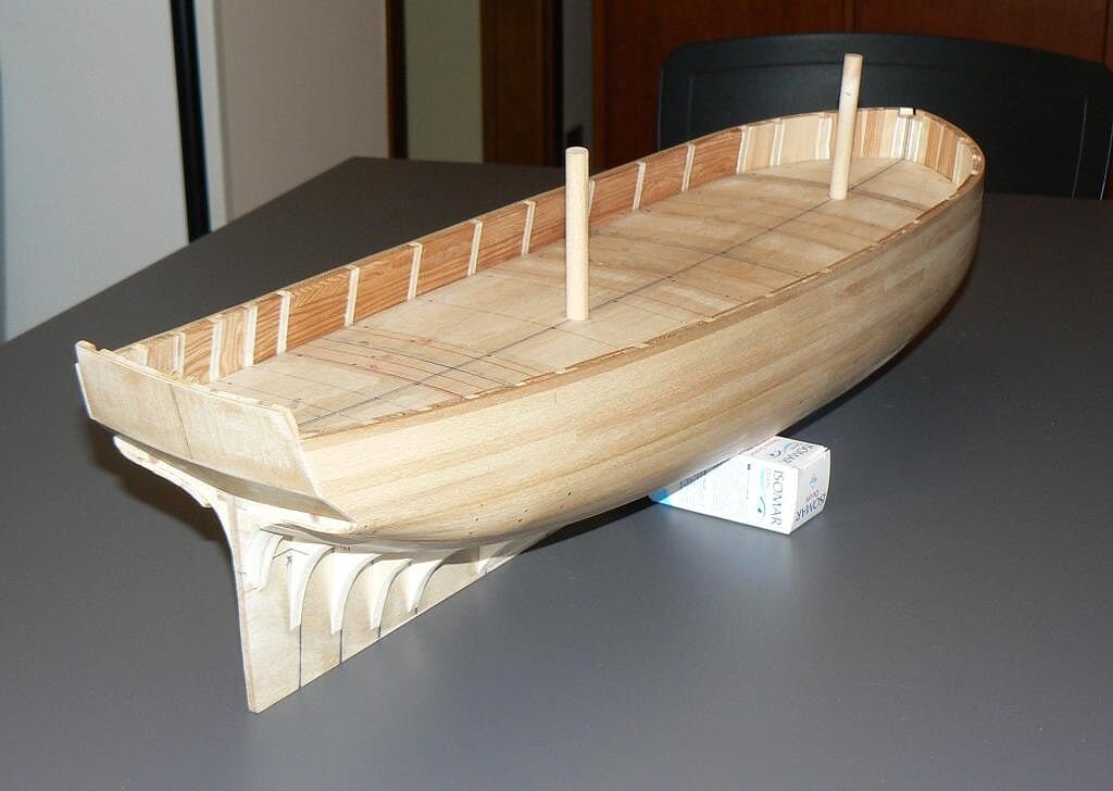
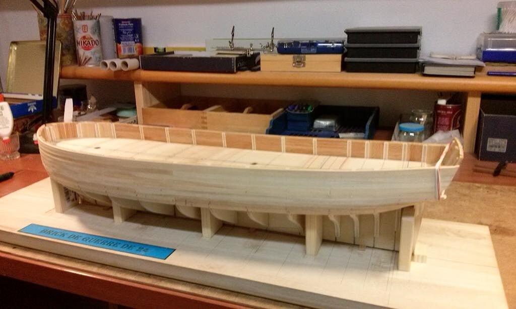
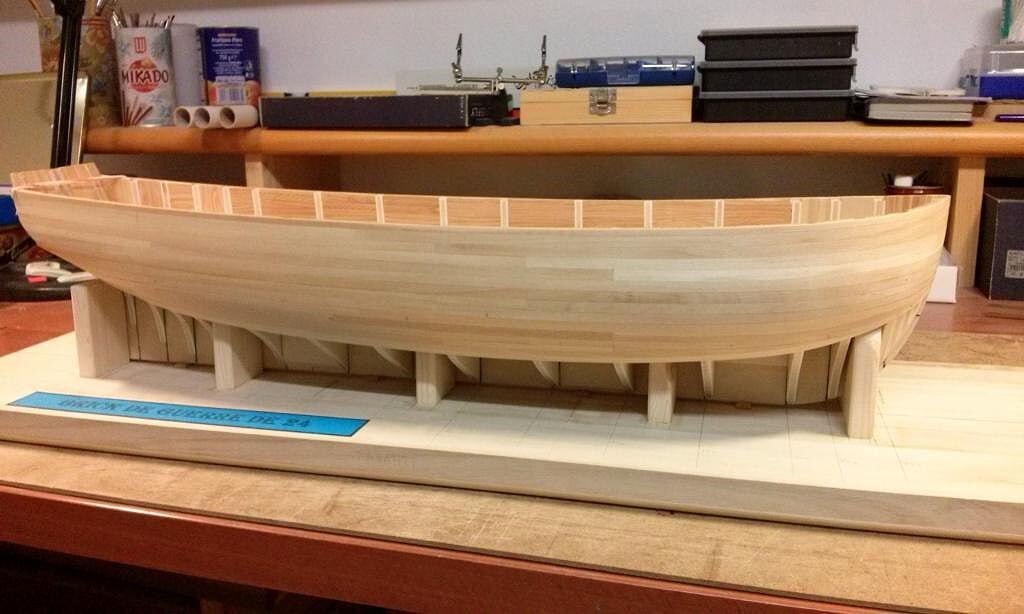
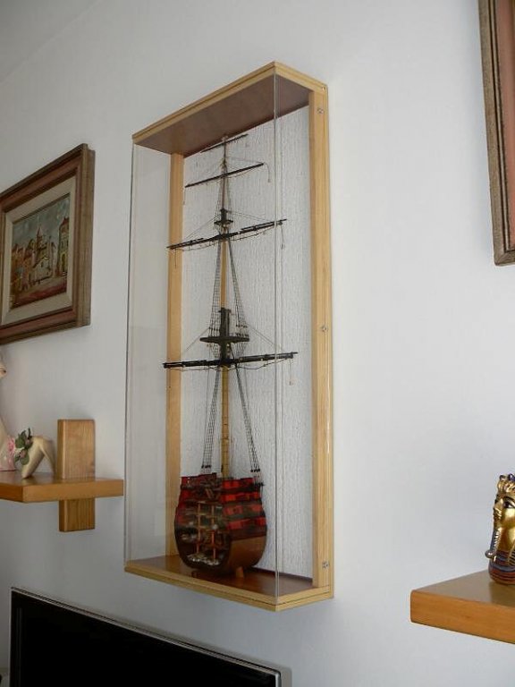
First two images show the entire hull capsized, on both sides. As you can see we are slightly more than halfway even if, maybe, the most complex part should be overcome. As my habit, as I progress with the planking, I level the surface with sandpaper. In this way I have left less work to do at the end.
01 Brick%20by%20JackAubrey/P1100103_zps304bb4f3.jpg
02 Brick%20by%20JackAubrey/P1100104_zps775ae2a7.jpg
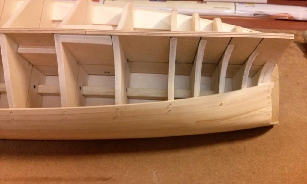
In the next image I'm showing a trick I use when I can not avoid gaps between a strip and its neighbouring. Keep in mind that this normally occurs over a small area, not on the entire strake. In this case, instead of sanding the higher strip, reducing its thickness, I prefer to paste another small strip on the lower strake. Next, when the glue is totally dry, I level properly the whole without the need to reduce the thickness of the plank in the involved area.
In the picture shown below you can see three pieces of this kind ready to be sanded and if you look more in deep near them you will see two areas already leveled. They are distinguished by a color slightly different.
03 Brick%20by%20JackAubrey/P1100105_zpsf1108e6a.jpg
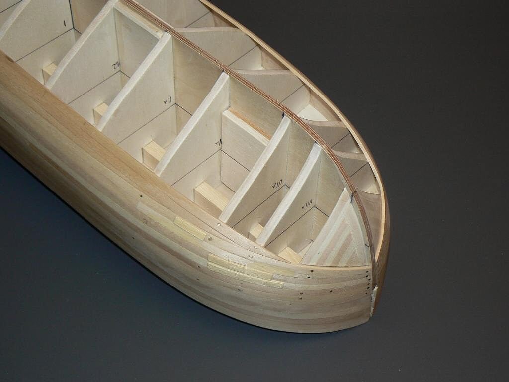
You can also see that the last two strakes downwards are interrupted before the bow and are cut diagonally. This solution is viable thanks to the fact that the double planking is planned and this allows to use a normal straight strip. To avoid this "trick" would be necessary to start from a much wider strip and cut out the right shape to follow the lines of the hull. I think those who are used to single planking know what I mean.
During the second planking this situation will happen again. However, having the intention to use for this second pass sheets of veneer from which to derive the strips, I should be able to adopt the correct method more easily and with less waste of timber. .
. . but we must also take into account that the hull will be covered with copper plates and, if this area will stay below the waterline these critical efforts may be waste of time. In that case I would not complicate my life to do something that will not be visible.
04 Brick%20by%20JackAubrey/P1100106_zpsfbe729b1.jpg
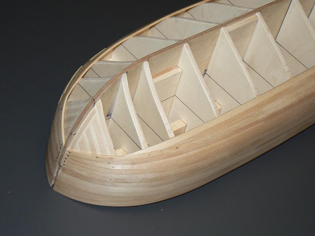
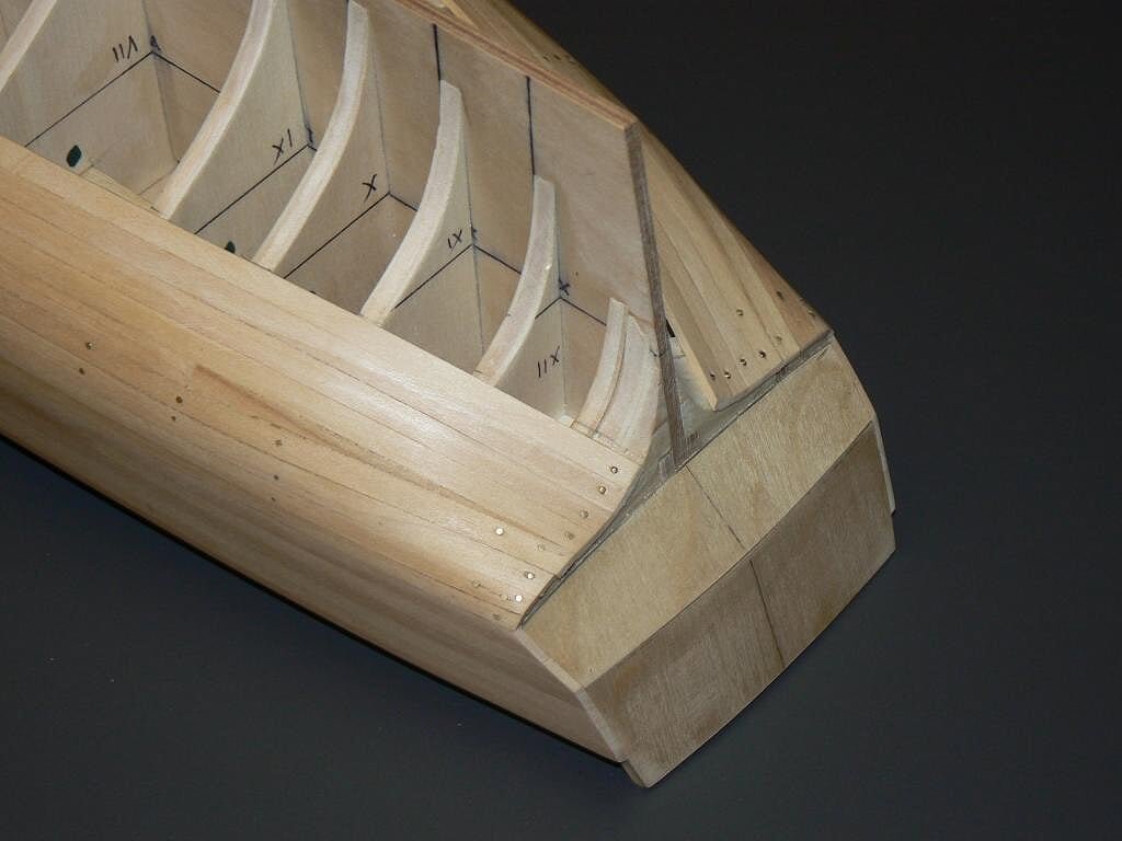
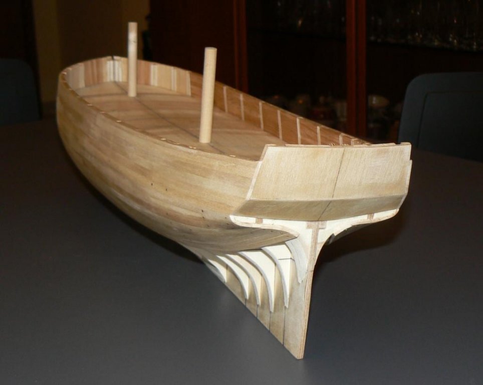
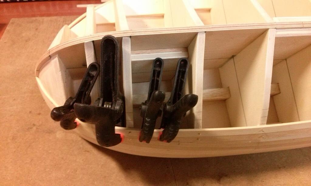
Finally, the stern. From what you can see from the photo below you probably understand that the transom is sharp corner shaped . . but it does not. In the model it is expected the transom be rounded. Here, too, I adopted another trick to speed up the laying of the first planking (it's 2mm thick). With such a thickness it's not easy to bend the strip to give it the rounded shape of the stern, so I made sure to have a very large underlying base on which pasting the strip with no need of bending but being sure it rests perfectly on the whole underlying base. Subsequently I'll shape round everything (obviously removing the brass nails) without problems being practically a block of wood and I'll have to worry about bending the strips only for the second planking, but with the thickness of 0.5mm. Definitely a much easier job.
But I must admit, to be honest, that it's the first time I try this "trick" . . hope it works.
05 Brick%20by%20JackAubrey/P1100107_zps7b47ce8b.jpg
I stop here this long exposure, not easy to describe only with words.
If someone do not understand what I wrote, which is highly likely, seen the way I explain probably not much clear and in a foreign, for me, language, please do not worry to ask for further clarification.
Regards, Jack.- Mirabell61, yvesvidal, hexnut and 3 others
-
 6
6
-
Tuesday, December 2, 2014
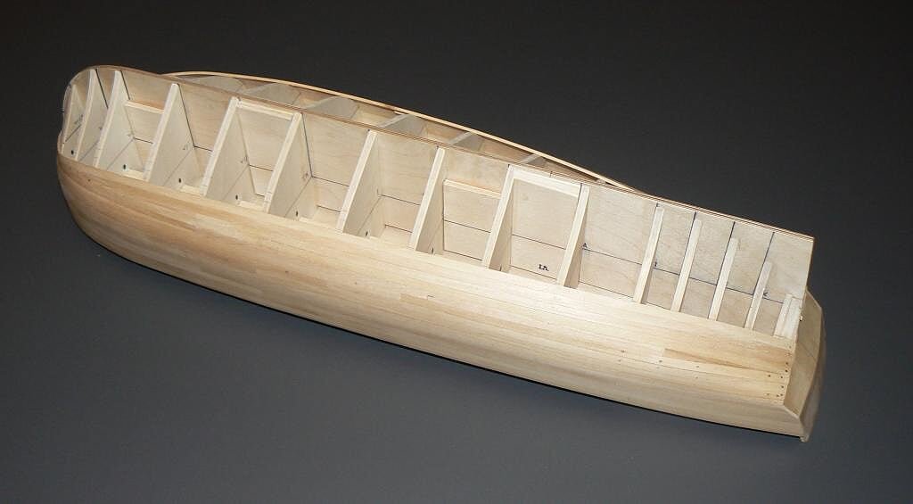
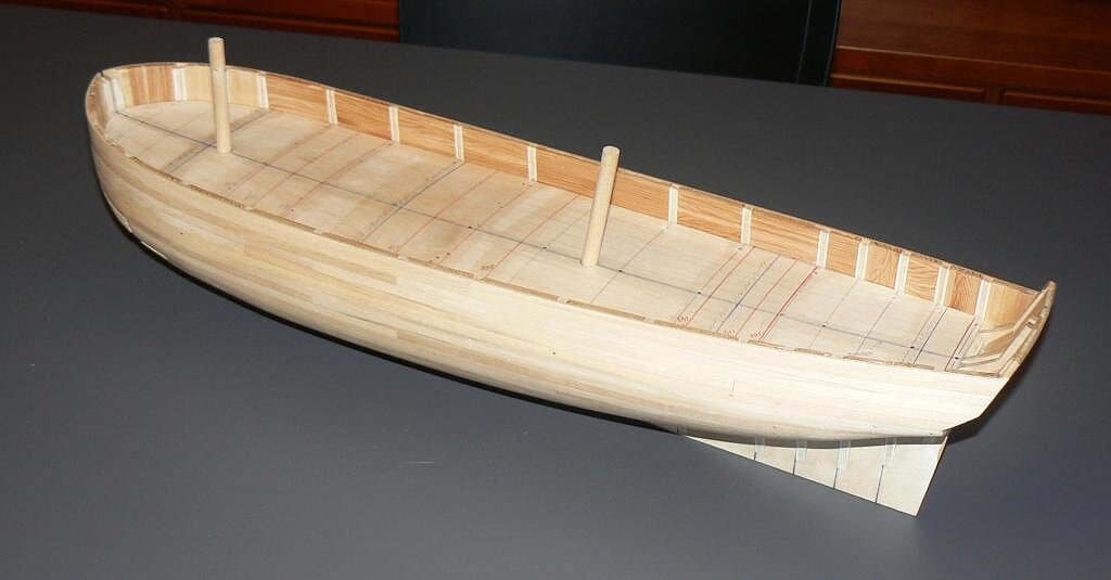
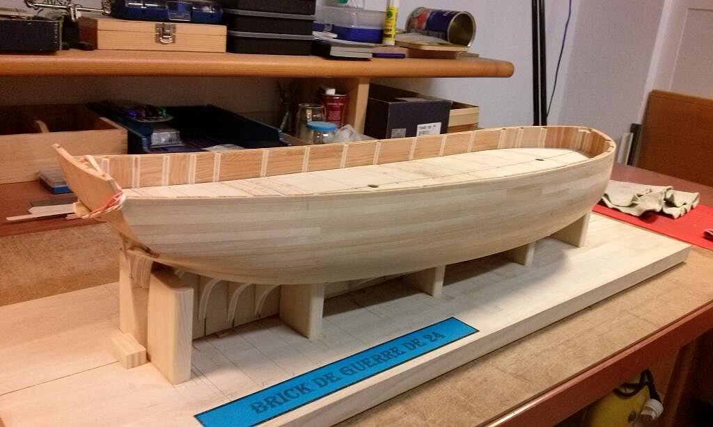
Yesterday I finally "finished" to install the planking on the hull.
As "finished" I clearly don't mean to have the entire hull planked, up to the keel but, as you can view, achieving the result to have installed on both sides the same number of strakes. Now I have to stop, otherwise I need to throw the building slip. I'll continue the remaining after the completion of the deck when the building slip at that point will not be useful anymore.
However, even if the shell is not completely finished, it's possible to see quite well the lines of the hull, which I like very much and which have nothing to do with the bulging and rounded forms of galleons and vessels I built until now .
This time the photos were shot with a digital camera, not with the smartphone, and are definitely better than the last published in my two previous posts.
01 Brick%20by%20JackAubrey/P1100091_zps6e113dbb.jpg
02 Brick%20by%20JackAubrey/P1100092.jpg
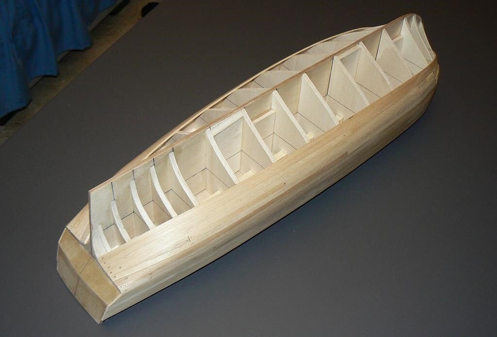
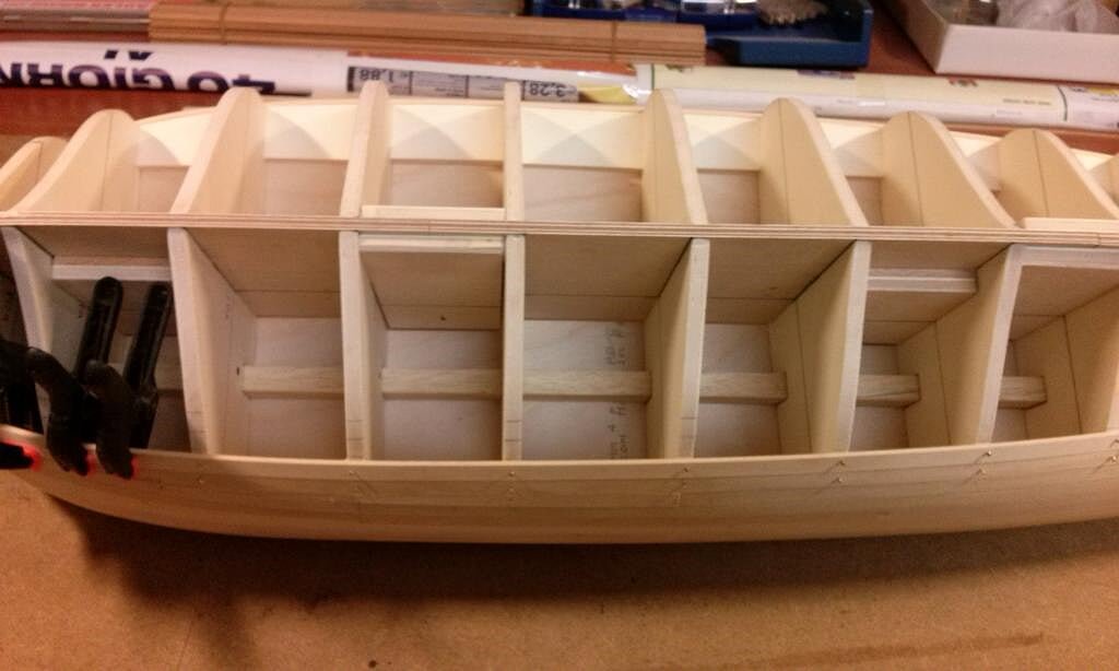
Until now I haven't encountered any particular problem while laying the planks. However I must admit that really it's not a easy hull. The bow seemed easier at the beginning, instead of at some point things got a little complicated. Aft however, where it seemed the hardest part so far has been a lot easier. Anyway these matters will be discussed in the next posts.
03 Brick%20by%20JackAubrey/P1100093_zpse21a9a90.jpg
04 Brick%20by%20JackAubrey/P1100095_zps45d7dc6e.jpg
05 Brick%20by%20JackAubrey/P1100094_zps4c1dbbb6.jpg
Regards, Jack.Aubrey. -
Posted: Sat Dec 29, 2007
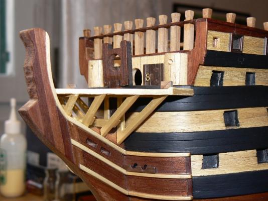
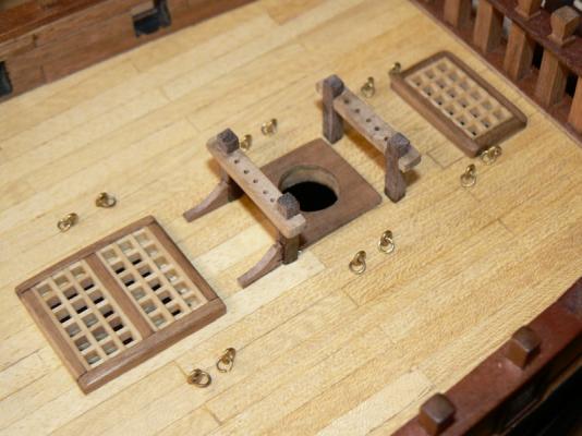
The following images show downwards, from right to left the cross timbers. There are four cross timbers in total and their name should be:
- stem head timber, the bigger one in the background;
- after head timber;
- middle head timber and, in the foreground,
- forward head timber.
(source: Anatomy of the ship - 32-gun frigate Essex)
I have painted with acrylic gold the timbers but I recognize that in these images you can have some difficulties to discover they are golden instead of the same color of the light wood.
I believe I need to apply some aging techniques to make the golden surface more realistic.

- WackoWolf, CaptainSteve, cristikc and 1 other
-
4
-
Posted: Sat Dec 29, 2007
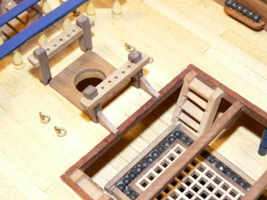
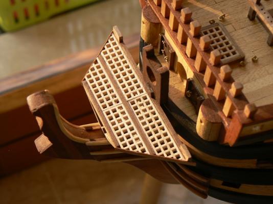
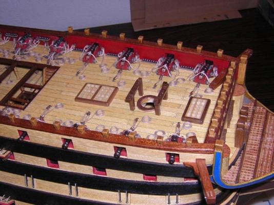
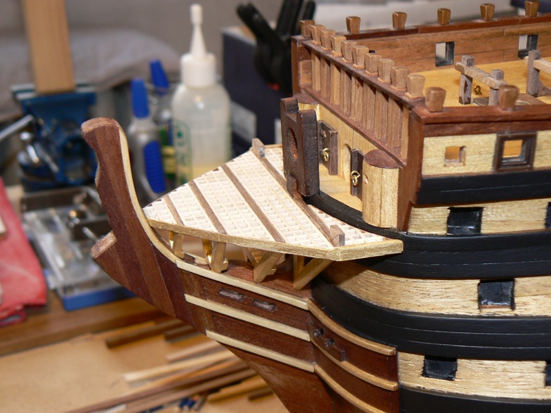
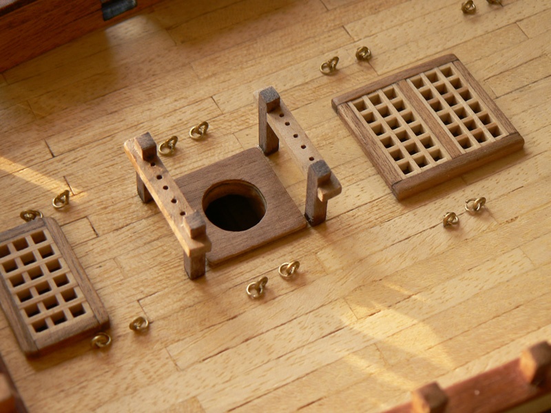
December 29th, 2007 - Prow gratings
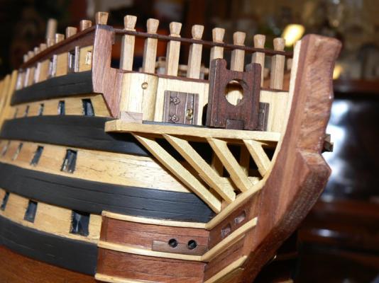
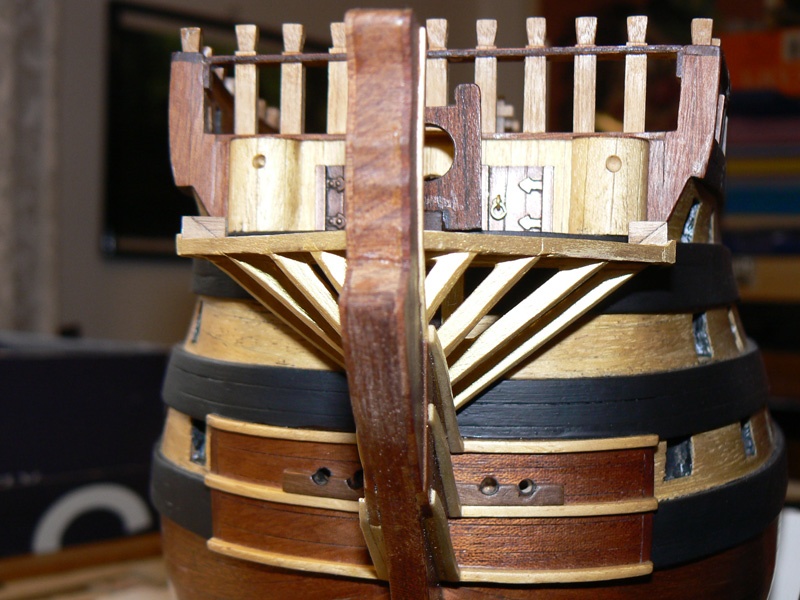
I'm now back to you with news about the gratings installed in the prow area, with its (now) completed supporting structure.
This new image shows the gratings seen upwards. The complex has evolved since my previous message of December 19th. I have completed the structure and I have definitely fixed it to the hull.
The gratings are now surrounding in their back the hull, filling completely that area. It was a matter of testing in place and adjusting something a little bit somewhere for several times before I decided to use the glue, but now it's definitely in place !!

-
Thank you CaptainSteve, I appreciated your comment . . Jack.Nice addition !!! Those columns really make the whole area stand out !!
-
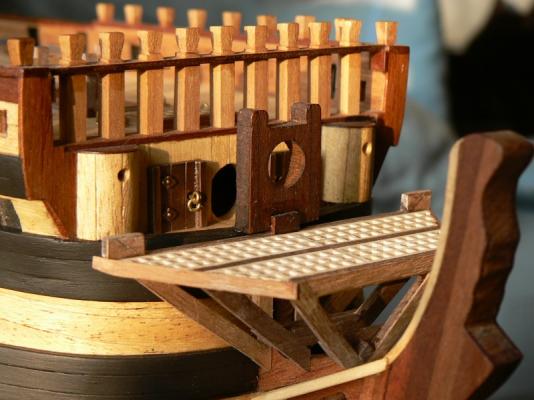
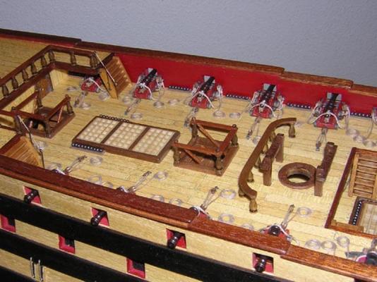
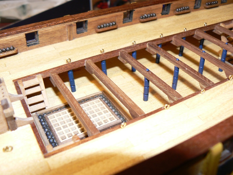
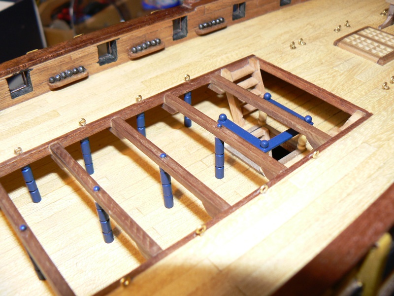
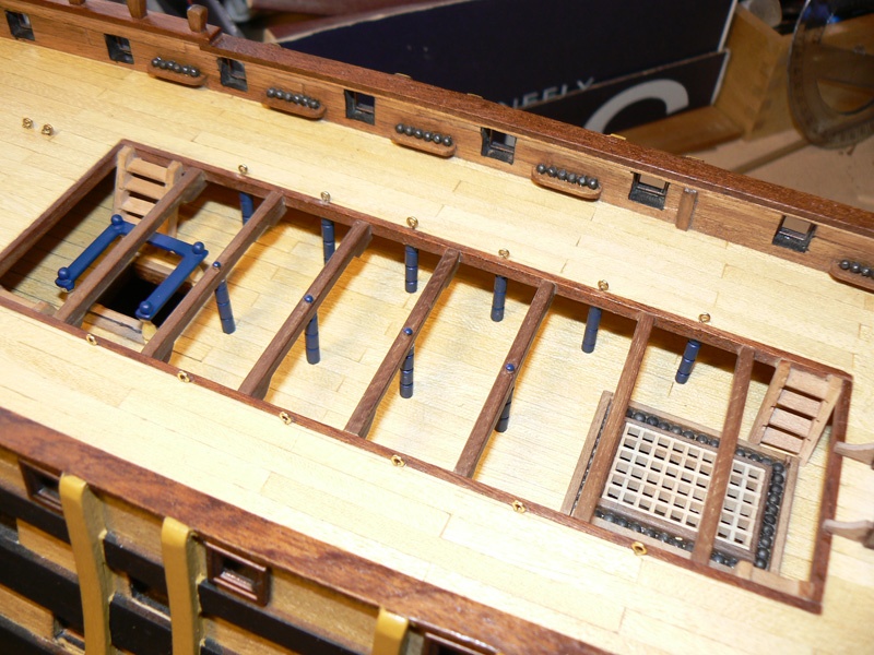
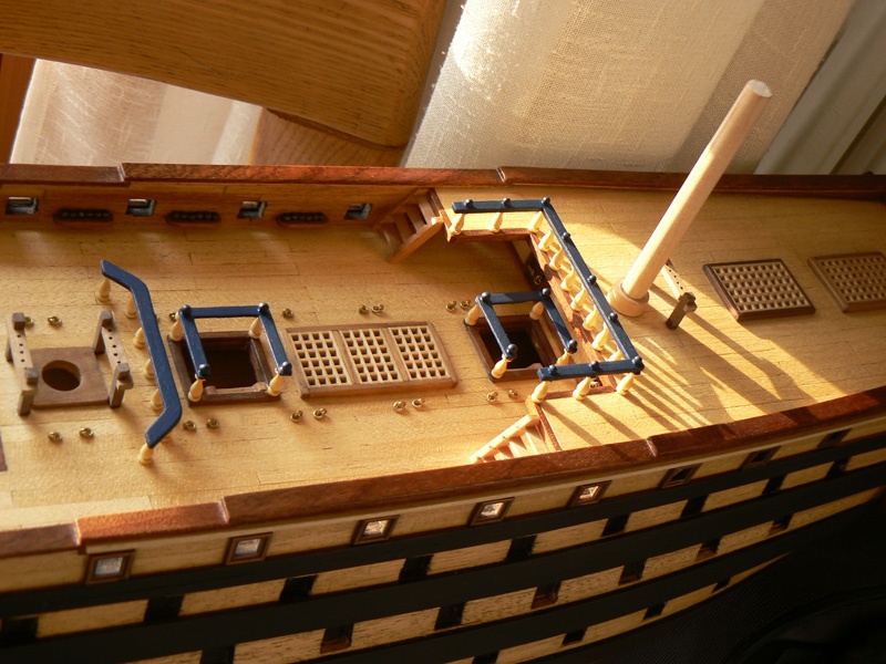
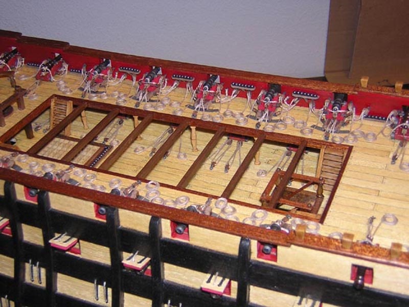
Posted: Fri Dec 28, 2007
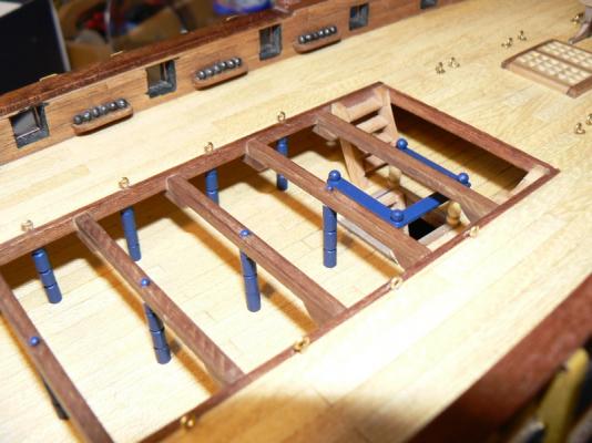
And this is the final achievement of many hours of working in building the 16 columns, painting then with blue and, last but not least, installing them between the upper deck and the quarterdeck.
This detail makes the area very, very realistic and I like it very much . . . . Do you agree ?
See you soon. Jack.Aubrey


- WackoWolf, CaptainSteve and GuntherMT
-
3
-
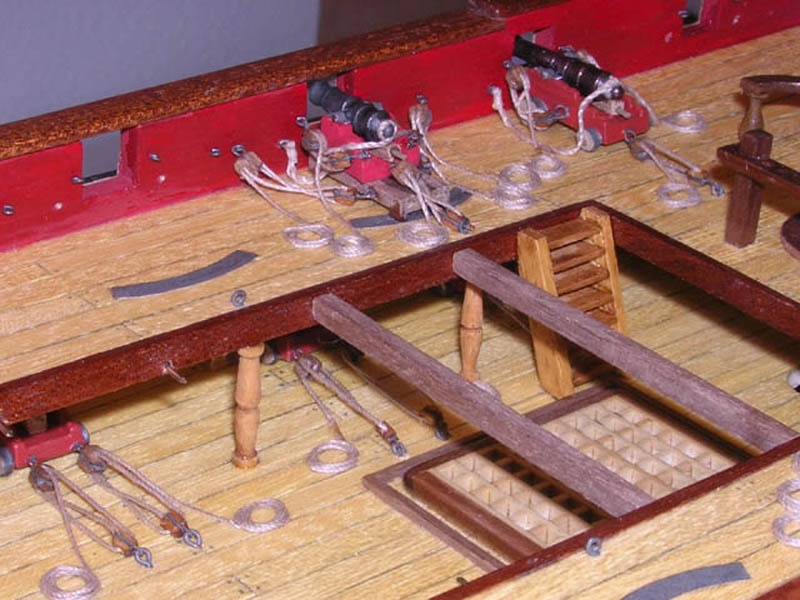
Posted: Fri Dec 28, 2007
I'm now working on adding new details to the upper deck and the quarterdeck.
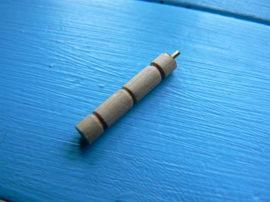
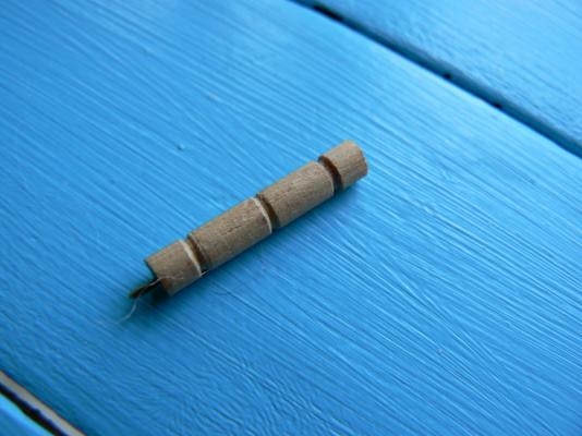
What you can see in these two following images are some kind of "home made" small columns. The real size of these protopype object is the following: 3mm. diameter, 18mm. length. So, the images are much more bigger than reality . . .
To build it I have used my Dremel minidrill.
I cut a piece of round wood and I mounted it in the drill in place of the drill bit. Then, with a file I made the three grooves. Then I cut the column to the proper length and drilled the two edges to insert and fix a brass nail in one side and an eyebolt in the other (when mounted in place).
- CaptainSteve and GuntherMT
-
2
-
Posted: Fri Dec 28, 2007
I have added some small details to the sheet bitts. These makes them more realistic than before ...

-
Friday, November 28th, 2014
This week, again, wasn't much productive, this because my now well known " meteorological ....". Finally yesterday I got the will to resume work: I continued managing the left side of the model.
Shortly:
- fix up the bulkheads on the left side to level them and create the right bevel angle; after the first experience on the other side, this time I went a lot faster and I finished this task within one hour during the morning. A quick housekeeping with the vacuum cleaner to fix the workshop and yesterday morning was over with satisfaction.
- During the afternoon I dedicated myself to apply the planking on the side just beveled. At the end of the session I achieved to install four plank strakes after which I needed to leave everything dry. I'll continue next Saturday.The first photo you see here below shows the left side of the model; here the situation is still "Work in progress" . . All the nails used to hold the planks are still in place and must be removed. Remember that these nails are not completely hammered and are easily removable with small pliers. Only a very small part of them are fully hammered and will be smoothed together with the planks.
01 Brick%20by%20JackAubrey/20141127_173547_zps3007289b.jpg
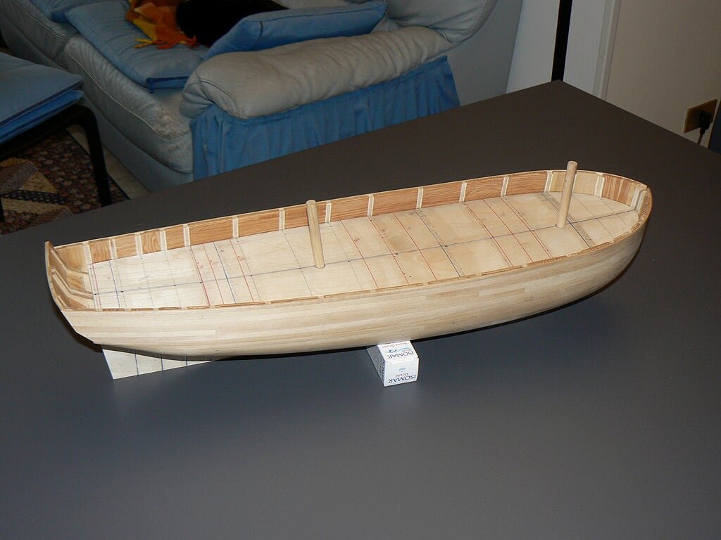
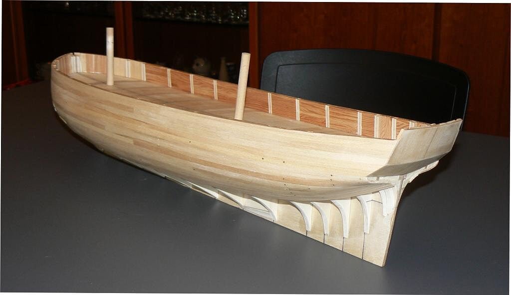
Next three images show the right side, where you can see it is no longer possible to install new planks because of the building slip vertical supports. This building slip, when also the left side will be equal, will lost its original purpose.
But first I want to use it during the deck planking.
This side have been smoothed and there are no more steps, grooves or humps.2 Brick%20by%20JackAubrey/20141127_173413_zpsf9e76628.jpg
03 Brick%20by%20JackAubrey/20141127_173507_zps239b3e31.jpg
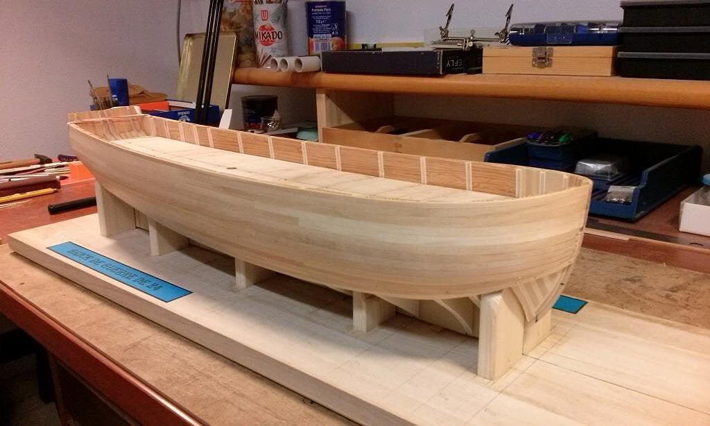
04 Brick%20by%20JackAubrey/20141127_173521_zps46d4abe5.jpg
Regards, Jack.Aubrey
-
Posted: Wed Dec 19, 2007
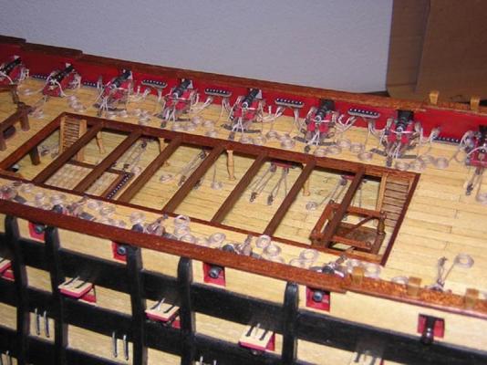
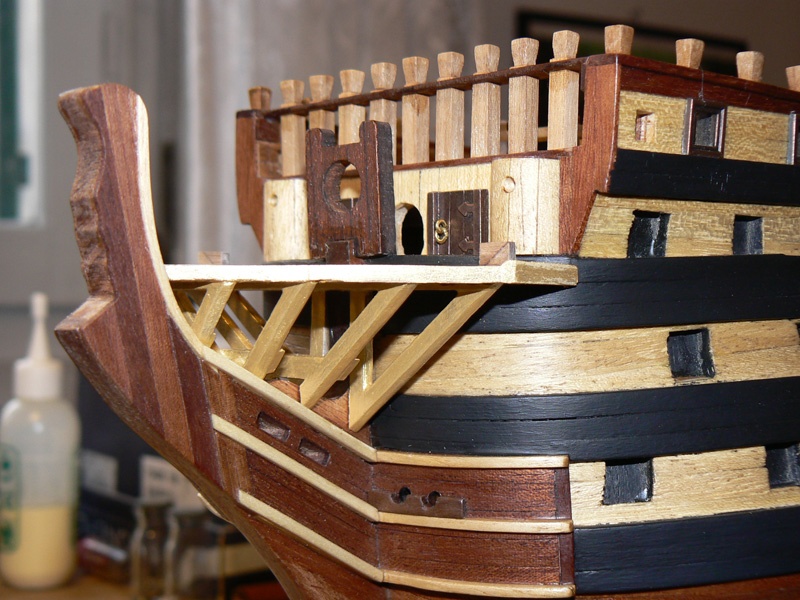
This is the continuation of the previous message where you can look at the structure installed in its proper place, but not yet fixed.
The three images here below show the area from different perspectives. I like it and until now I'm satisfied.
Looking better at the third image it becomes evident that there is a gap between the round hull of the prow and the overlooking first grating. This gap will be filled with ledges or with another grating properly shaped when the structure will be permanently fixed to the hull.
What I need now is to find some time to continue this work, but the Christmas period is here and everybody is very busy and I'm not different.
I want also get this chance to wish Idea Merry Christmas and Idea Happy New Year to everybody. Your Jack Aubrey.

- GuntherMT, WackoWolf and CaptainSteve
-
3
-
Posted: Wed Dec 19, 2007
I'm back again to explain the work that is currently engaging me: the construction of the structure, I think the right term should be "the head", located at the prow, between the figurehead and the beginning of the forecastle.
It is a very complex area but the main problem I'm encountering here is to identify the proper terminology. I am using as reference the 32-gun Frigate Essex, of the Anatomy of the Ship series, page 48, 49, 50 and 51.
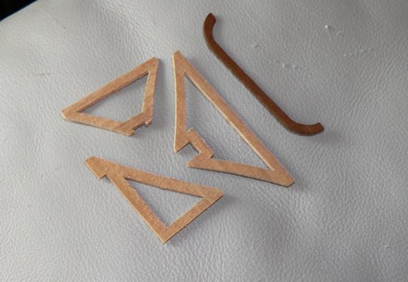
The raw materials supplied by the kit manufacturer were:
1) gratings to be mounted, glued and cut at the right size
2) pre-cut plywood (2 mm.) for the cross timbers and up to three rails (main rail, middle rail and lower rail).
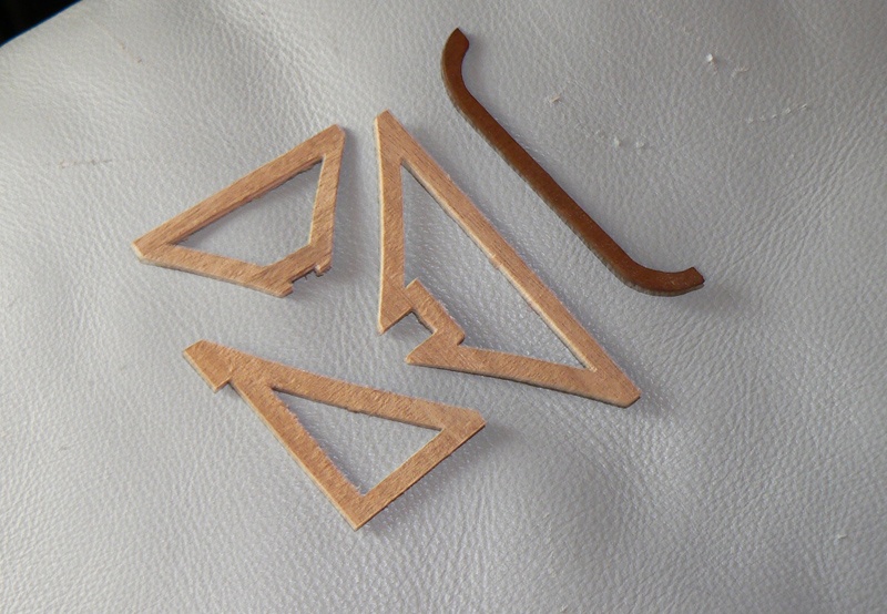
The first image shows some of the cross timbers pieces when separated from the plywood sheet . . . . . briefly I wasn't satisfied of them, first of all because of the poor quality of the plywood.
So I decided to discard everything and use them only as templates for my own cross timbers. To do them I have used walnut stripes of 2x4mm and 0,5x4mm. I have built the timbers by glueing the two types of wood in order to frame-up the angles and have more surface to fill with glue. The resulting width of the timbers is 2.5mm. but I thing the pieces are much better and probably more realistic. From another point of view I have used the gratings supplied by the manufacturer without any change.
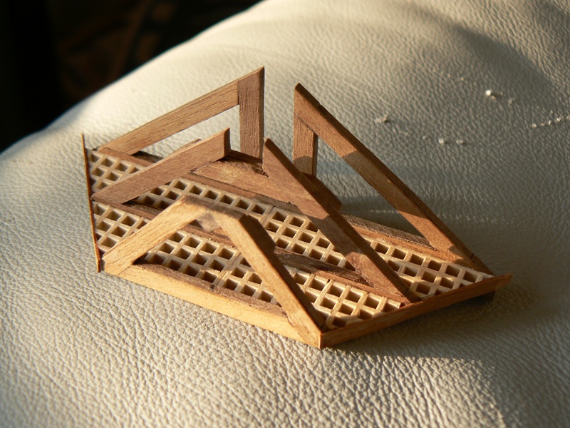
The second image shows the structure partially finished and as it is now. I need to build another small cross timber to install in front of the other three.

- GuntherMT, CaptainSteve and WackoWolf
-
3
-
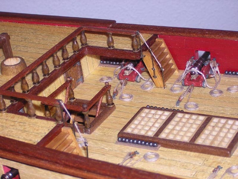
Posted: Sun Dec 16, 2007
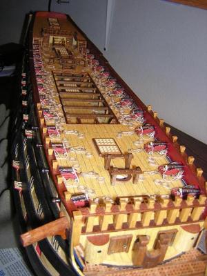
Here you can see another work I've recently done on my Santìsima Trinidad.
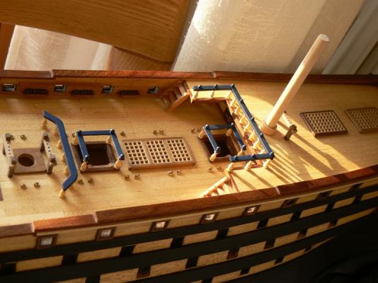
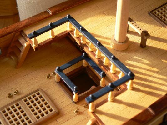
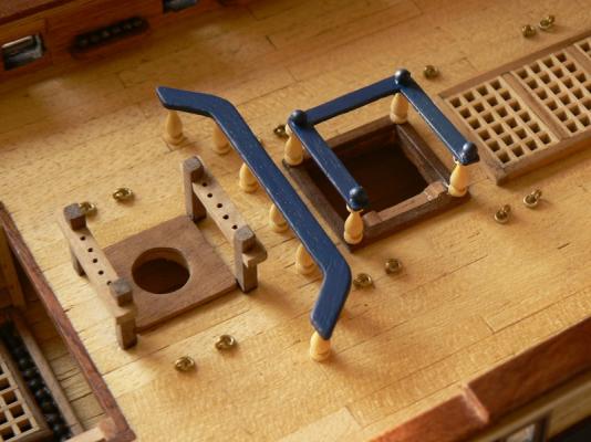
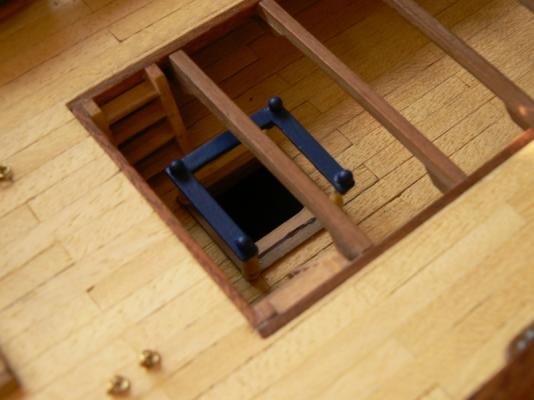
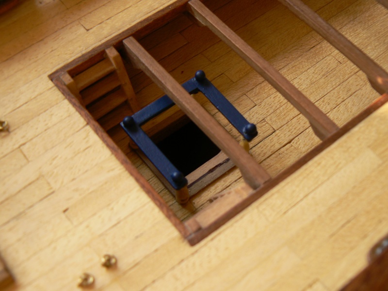
Companionways with rails and other details. Very small details on the quarterdeck, but very much visible. Finally I have decided to paint the rails with a blue paint because the color of the wood used wasn't much omogeneous and I didn't like it.
I like particularly the ballusters (the columns made with boxwood).
- CaptainSteve, yvesvidal, GuntherMT and 2 others
-
5
-
Posted: Sun Dec 09, 2007
Last Friday, December 7th, 2007, I finally resumed the work on the Santìsima Trinidad. It was more than three month I did nothing around her, mainly because the italian postal service lost a monthly shipment from the kit manufacturer.
But now I am back again, although I have done few work ... some small deck details ... but what is important is that, as we use to say here in Italy, the "ice has been broken".
I started to work following the instructions of the kit magazine issue n° 74 (until now we are at the issue n° 95): this means that I have a lot of work to do.
As soon as it will be worth to take photos I will publish them. See you soon. Jack.
Posted: Sun Dec 16, 2007
This is the first result of my resumed work on the Santìsima Trinidad. The attached image shows the fore topsail sheet bitts (on the left) and the main top bowline bitts (on the right). The area involved is the forecastle.
There are three additional bitts, two before and after the main mast and one after the mizzen mast.
To fix the bitts to the deck I have first drilled a hole in the vertical columns and inserted and glued a brass nail into it. Once cutted the nails head I have then drilled the deck in the proper place and, by inserting in the two holes the prominent edges of the nail, I have definitely fixed the whole with glue. It seems quite robust ....

- GuntherMT and CaptainSteve
-
2
-
Posted: Fri Nov 16, 2007
I'm back on this topic after my trip in Ireland just to inform everybody that I haven't yet started any kind of work on the Santìsima Trinidad (ST).
The reason is that, just sometime before to resume the ST model, I received a telephone call by the model-shop of my choice informing me that the timber I ordered for the second planking for my simultaneous build (74 gun ship San Juan Nepomuceno ) was finally available. So I went to buy it and after that I was not able to resist to the wish to try to lay some planks.
What then shortly happened is that now I am fully involved in this new task and the Santìsima Trinidad is still idle ......
Some days ago I published on the San Juan Nepomuceno topic (unfortunately totally lost after the previously mentioned crash) some images of the Santìsima Trinidad built by another italian modeler. He is here known with the nickname FAM and this message is a tribute to his craftmanship.
His images started some positive comments and participations in that topic ..
He does not publish his work on this site (I tryed to convice him ..) but he has authorised me to show you some other pictures of his model so I have posted here six photos of his masterpiece, showing the tremendous amount of work done by him on the quarterdeck of the ST.
It is also important to know that his ST, like mine, is built starting from the De Agostini parts work, with some changes/customisations.
So, in the waiting of some good news from my ST, for the moment I hope you will appreciate this other ST ... It is worth appreciating.
See you soon. Jack.


- CaptainSteve, GuntherMT and WackoWolf
-
3
-
Posted: Fri Oct 26, 2007
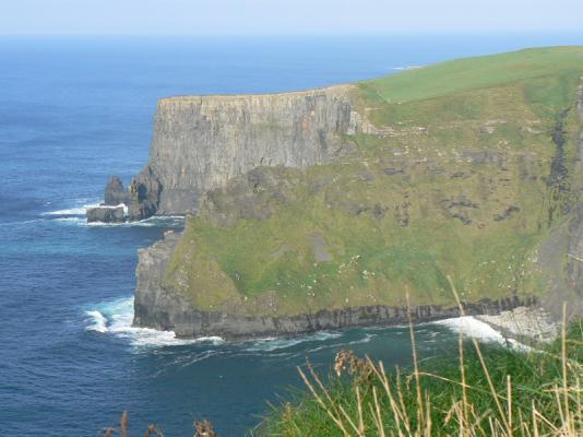
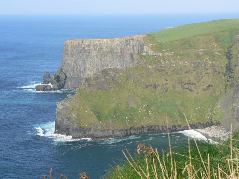
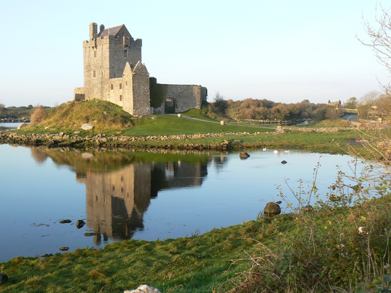
I'm now back fron my trip in Ireland.
These images give you a "appetizer" of which kind of beautiful lands, landscapes and seascapes you can find there .....
In the next days I will resume my work on the Santìsima Trinidad, so let's see us soon . . . Jack.

-
Posted: Tue Oct 16, 2007Latest news ...... Today I have finally received from the magazine editor the missing (in action) shipment, the famous 19th ... So, now I have all the materials and the building instructions necessary to restart my work on this model.But you must be patient to see something new since this saturday I will start a trip with my wife in Ireland (Dublin and Galway) and I will be back only the following friday.
-
Posted: Fri Sep 07, 2007
Today, while I was working on the San Juan Nepomuceno I have received a monthly shipment from De Agostini (the magazine editor and kit manufacturer).
Unfortunately this is the shipment n° 20 (this means it's 20 months I'm working on the Santìsima Trinidad) and I am still missing the 19th. I have done a quick review in the hope I can do something but mainly all the task here described are dependent from some other task contained in the missed numbers.
Still some time to wait .... Jack. -
Very interesting and detailed build log . . I didn't read it before. I bookmarket it for the future. Jack.Aubrey
-
Sorry to hear that you are having problem with getting the issues. This is one of the problems people seem to have. And now that they will ship to the USA I have doubts about doing one of there kits. Hope things get taken care of.
Hi Wacko, rememeber to check always the date I report on each message I publish on this topic.
As I wrote in the first message about this model, I'm trying to recover a build log lost with the crash of Modelshiworld time ago. So, this date is important because I'm describing facts happened much time ago. In the case of my last message this belongs to September 2007 !!
Anyway, what you write is really a right concern. This in Italy was true some years ago, but now is much better, after the mail service acquired a private company to manage parcels. The delivery of the montly shipments, that has a different management of the news-stand channel, rely in Italy mainly on the public mail service that in +/-2007 was much less efficient that today. De Agostini is usually regular with its shipments but then the "courier" passes to the mail service and delays may happen. This still is true in some period of the year, tipically in August (holidays), Christmas and Easter.
But every country has its own postal service and this service may be more or less efficient that in Italy.
-
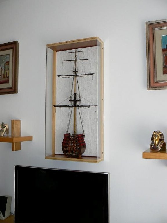
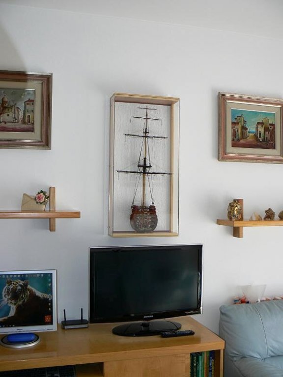
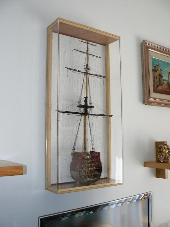
Thursday, March 22, 2012 - The model in the finished display case
After a long time, during which I waited in vain news about the sails from the tailor, I'm still waiting to see something of them (!!)
In the meantime, due to the need to deliver it to the Ship Modelling Association "Magellano" who wants to exhibit this model at a planned fair/exhibition of ship models in Verona, the homeland of Shakespeare's Romeo and Giulietta, I decided to install this model into its finished display case before releasing it.
Today in particular, after the return from Verona's exhibition, I proceeded to place it in its final position in my house.
Below are some photos of this new "picture" although I sincerely hope to receive soon its sails in order to install them and finally put an end to this project.
Regards, Jack.Aubrey.
01 P1080104.jpg
02 P1080106.jpg
03 P1080107.jpg
04 P1080108.jpg
-
Posted: Wed Sep 05, 2007
September 5, 2007
I'm in trouble with the monthly shipments of the magazine (and the related builing material and instructions). My last receipt was in June and today the july and august issues are still missing.
I called the De Agostini's customer service and I was said that most probably it is a problem generated by the public post service and that they cannot consider their shipment lost (and consequently re-issue a new shipment) before 60 days from their shipment date. For the july one this will happen on sept. 20th.
So, I had to stop any activity on the Santisima Trinidad more then 15 days ago. I will continue with the San Juan Nepomuceno soon. Jack.
-
Saturday, November 22, 2014
Not too much to show about the work done since my "meteorological disease" has finally finished with the end of the rain: during this week I installed the "considerable" number of "nine" strakes of planks on the right side of the hull.
I publish below some pictures just to show something, but I do not think they are very enlightening.
In particular there are two aspects of some interest:
a) the first, positive, aspect is in the areas of midship and aft. The planking is growing very well, without the need of tapers and with the joints between the planks of total satisfaction and") the second, I would say negative, at the bow, where even in the presence of planks strong tapering, it is impossible to apply strights strips; here you should design planks starting from preformed strips probably 2.5-3cm wide and cut them accordingly to the shape of the hull. A job that involves an incredible waste of timber and without practical effects as it is expected the second planking.
the second, I would say negative, at the bow, where even in the presence of planks strong tapering, it is impossible to apply strights strips; here you should design planks starting from preformed strips probably 2.5-3cm wide and cut them accordingly to the shape of the hull. A job that involves an incredible waste of timber and without practical effects as it is expected the second planking.
So I adopted the technique to install some planks so that they follow their natural curvature on the hull even if this forces to end the strip earlier, with a diagonal cut. I remember the the process of preparing "ad hoc" planks would be much easier with the second planking due to the planned use of sheets of veneer from where can I get the due shape in the easiest way. Furthermore, to explain why also this efforts could be unuseful, under the waterline there will be the copper plates, so everything becomes a theoretical exercise because all this work will result invisible.
Usually every three/four strakes applied, I sand them in order to advance in parallel the planking and its sanding. This costs me less efforts than doing all the sanding the end and allows me to verify periodically the work done. In addition, since it's a matter to lose only few minutes, I avoid the temptation to use power tools that are usually very efficient but also very dangerous if their use is not careful and could result in damaging the work done: here I prefer the old-fashioned manual process.
Another trick that I usually adopt, is to pass a brushstroke of diluted PVA on the planks, this dries almost immediately and helps to seal better the grooves between the strakes and strengthens the wood surface. It is a little trick and/or fixation that probably every modeller holds in his past experiences.
Now, however, I have no more excuses: the next activities are to get the same results on the left side of the model. In fact I cannot proceed on this side with the planking otherwise my building slip is no longer usable. I prefer, once finished the left side, use this building slip and his undeniable stability to apply the deck planking: a new and stimulating experience. .Sincerely, Jack.Aubrey.
01 Brick%20by%20JackAubrey/20141121_180448_zps713219e3.jpg
02 Brick%20by%20JackAubrey/20141121_180455_zps87fe942c.jpg
03 Brick%20by%20JackAubrey/20141121_180502_zpsb3f479f6.jpg
-
Posted: Sun Aug 19, 2007
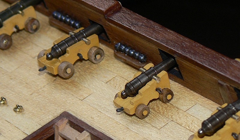
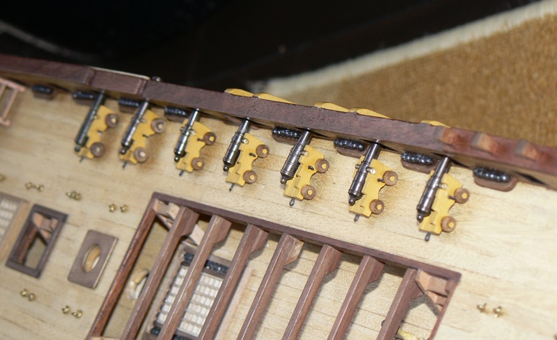
August 19th, 2007
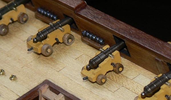
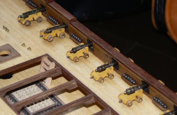
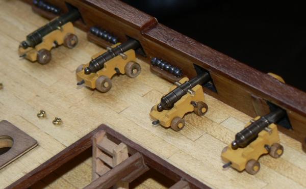
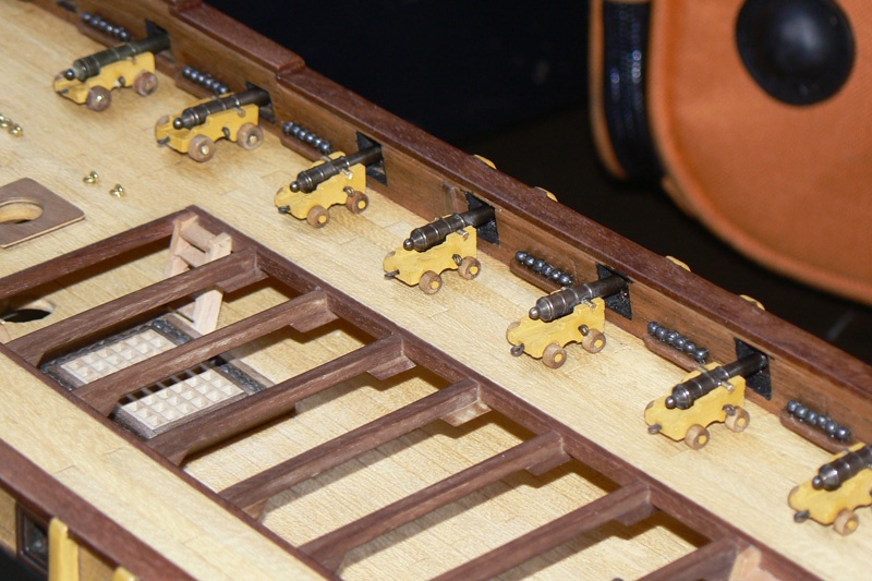
Here are plenty of images of Santisima Trinidad's ordnance. In these days I have built ten new guns. These guns are in accordance with the second type mounted on the quarterdeck. They are smaller than the other 10 previously build and documented. In any case I have positioned them near to the other type in a way to make possible comparisons between them.
The first image is a very close view of both models. The image is much bigger than it is in the reality and you can see some details that are not visible naked-eye. And they may appear imperfections ...
That's all. Your sincerely. Jack.
- GuntherMT, WackoWolf and CaptainSteve
-
3
-
Posted: 16/10/2011
Tomorrow, October 17th I'll go back to my home after a short holiday at my daughter's house near Pisa. I have been here in Pisa for almost a month but anyway I am very sad to leave my daughter alone.
On the other side, a positive thing when I'll be back at home is that I can resume my ship modelling hobby. At home, with regard to the section of the Santisima Trinidad, I have to resume two important things:
1) the plexiglass artisan phoned to inform me that the case is ready; so on that front I should be in the final phase;
2) for the sails, I did some tests while I was here in Pisa and now I have everything clear on how to proceed; I tryed to cut and tuck, ready for the final seam, but I wasn't able to sew them because of my TOTAL inability to make straight seams with the sewing machine.
I thought I could at least try with my wife or daughter but unsuccesfully. This confirm my decision to rely on third parties. As soon as I'll be back I'll involve a tailor, as I had in mind from the beginning, and I'll solve the problem.
So a little patience and then I'll have finally finished this blessed project that has been going on for more than two years. In the meantime I'll work on the Soleil Royal, another model I'm building: what is expected here is the second planking . . .
Best regards, Jack.Aubrey


Santìsima Trinidad by jack.aubrey - De Agostini - Scale 1:90 - Full Model
in - Kit build logs for subjects built from 1751 - 1800
Posted
Posted: Sat Jan 05, 2008
I'm back with the S.S. Trinidad and a new task I'm achieving: the completion of the rudder. This time, to help understand the complex terminology, I have used a new powerful tool (multifunction laser printer bought yesterday) to scan a page of the book "Anatomy of the Ship - The 32-gun Frigate Essex". The image is here presented first, followed by my own rudder.
More in detail the task consists of:
1) - fixing of the pintles (26), seven in total, to the pintle straps (20);
2) - installation of the gudgeon straps (25), in their correct place:
3) - insert the nail heads in the proper places at the gudgeon straps;
4) - painting the straps with a 1st coat of paint (primer for metal) and another 2nd coat with Humbrol gun-metal.
5) - installation of the eyebolt (12) and the ringbolts (13);
1): The second image shows the rudder as it was left unfinished some weeks ago, with only the pintle straps installed and painted. Now it is time, following the instructions of the kit manufacturer, to install the pintles where the red arrows in the 2nd image point.
The kit instructions say: "with a fast adhesive for metals, fix the pintles . . .".
Thinking more about I had three choices to do this:
a - use the cyan acrylic glue (gel), needs few seconds to dry but probably not strong enough;
b - use the epoxy resin glue (not too fast, at least 15 minutes to dry, 24 hour to be completely hard), probably the best choice among glues;
c - don't use any kind of glue but perform a tin welding; this last option forces me to fix the pintle on the gudgeon straps instead of on the pintle straps which are already installed; it's probably the best choice at all provided I'm able to make a welding.
Finally I decided for option c) and I started to train myself to weld.
I already had the electric welder tool, the tin and the welding acid (from my father in law) so I made some trials with some brass strips and rods several times until I was sure of my technique.
Then I performed the real task, achieving a very good result.
2): Now it was time to mount the gudgeon straps at the sterpost and there was a significant problem: the thickness of the first (close to the pintle) was lesser than the thickness of the latter. So I had to perform seven grooves in the sternpost in order to match the two. The difficult thing was to do the grooves in the proper position. A lot of patience ...
But finally, by using the epoxy resin glue, I fixed them in place with a very complex operation involving: masking tape, few nails, clamps and seven hands ... and now the rudder is totally in place and is also turnable right and left without any fear thank to its high breaking strength.
3): Third I started to drill and insert the nail heads into the gudgeon straps. Here I had to reduce a little bit the head of the nails to simulate the proper scale. I achieved this with the Dremel power tool, inserting the nail in place of the drill bit and working on the head with a fine file until it is reduced properly. Again, a lot of patience ..
4): I have finally applied a coat of primer on the straps and now I'm waiting the paint becomes dry to continue . . . .
. . . so my amazing story ends here . . . see you next time. Jack.