HOLIDAY DONATION DRIVE - SUPPORT MSW - DO YOUR PART TO KEEP THIS GREAT FORUM GOING! (Only 13 donations so far - C'mon guys!)
×

kirill4
-
Posts
907 -
Joined
-
Last visited
Content Type
Profiles
Forums
Gallery
Events
Everything posted by kirill4
-
 Mark, Each time I'm reading your posts I start thinking why human life such too short!!! :)))!!! at least my life obviously to short to complete all my modelling plans :))) still can't finish my curent project with galleon... and meanwhile constantly dreaming about how to build SR kit or gallera or chebeck kits ...??? I'm very satisfied that when I will be ready for that kits ,I will have your build log as REAL guidance!!! Thank Your very much for sharing your ideas and achivements!!! All The BEST in 2021!!! Kirill
- 2,696 replies
-
- 3
-

-
- heller
- soleil royal
- (and 9 more)
-
Good day Olga , Very accurate work !!! It was Just pleasure to watch it in details ! Great job!!! And Thank You very much for your video posts about ships modelling books and tricks how to make foto- all very usefull information !!! All The Best In 2021!!!
-
guys, just tried to make reverse translation from english to russian my posts...it looks like abracadabra of 10-15%my written text I'm very sorry for inconvinience when you are reading my "english" posts 🤪
-
guys, just tried to make opposite translation from english to russian my posts...it looks like abracadabra of10-15%my written text I'm very sorry for inconvinience when you are reading my "english" posts 🤪
-
guys, just tried to make reverse translation from english to russian my posts...it looks like abracadabra of 10-15% of my written text I'm very sorry for inconvinience when you are reading my "english" posts 🤪
- 265 replies
-
- 1
-
-
- Golden Hind
- Airfix
- (and 1 more)
-
guys, just tried to make reverse translation from english to russian my posts...it looks like abracadabra of 10-15 % my written text I'm very sorry for inconvinience when you are reading my "english" posts 🤪
-
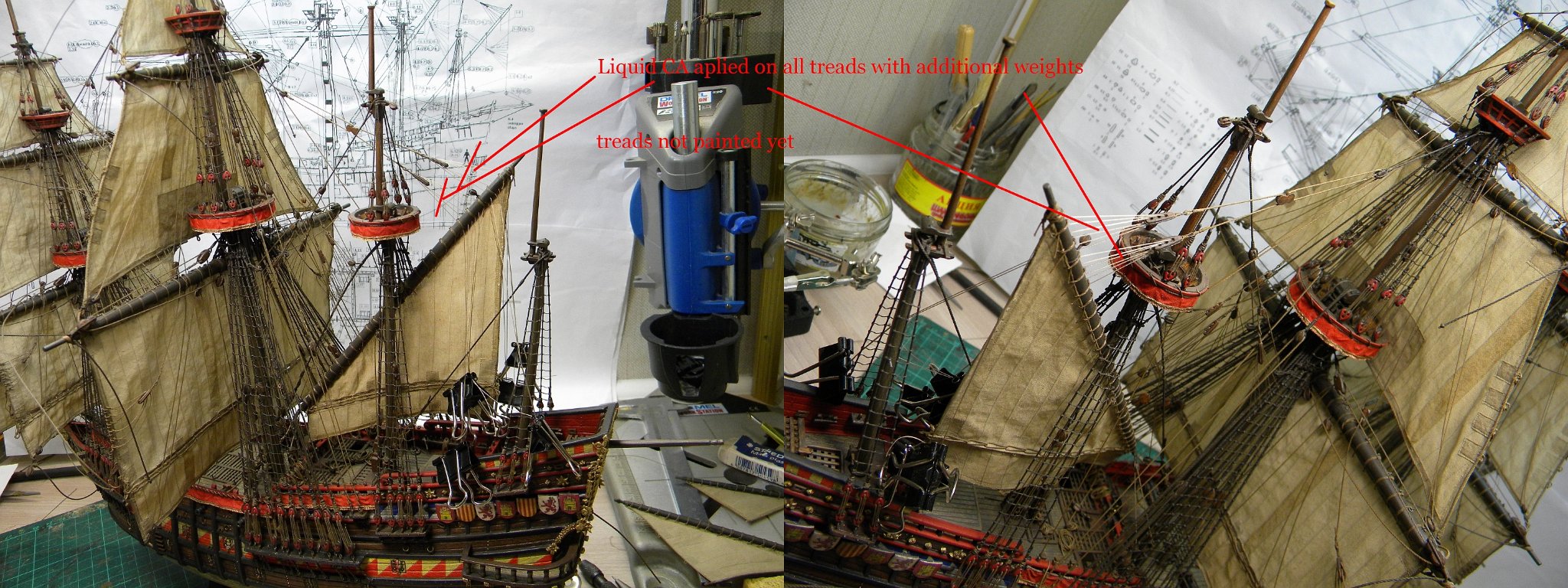
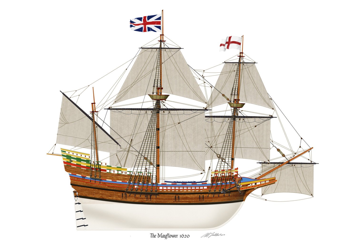
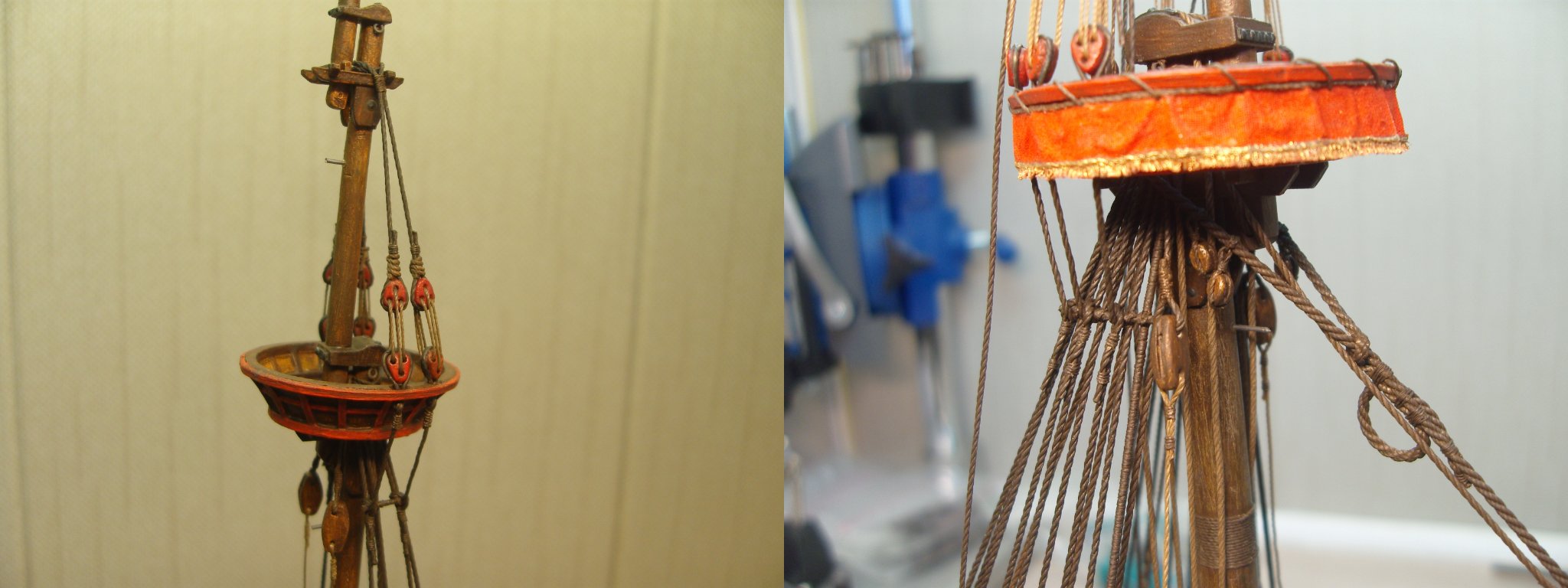
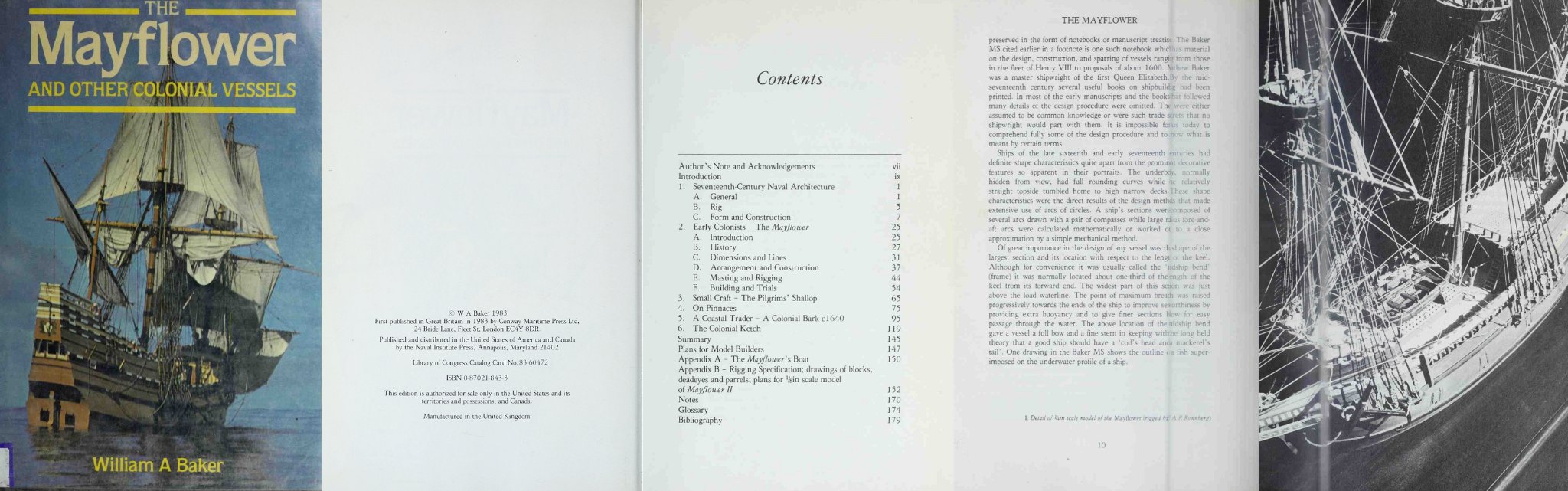
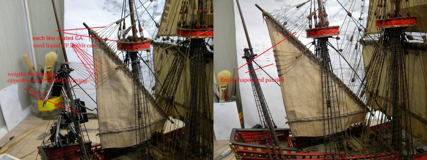
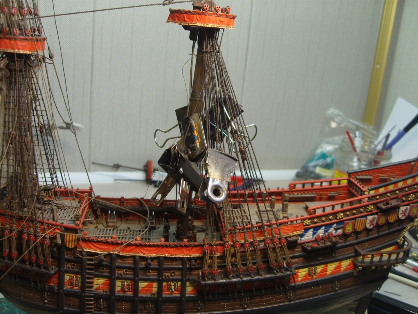
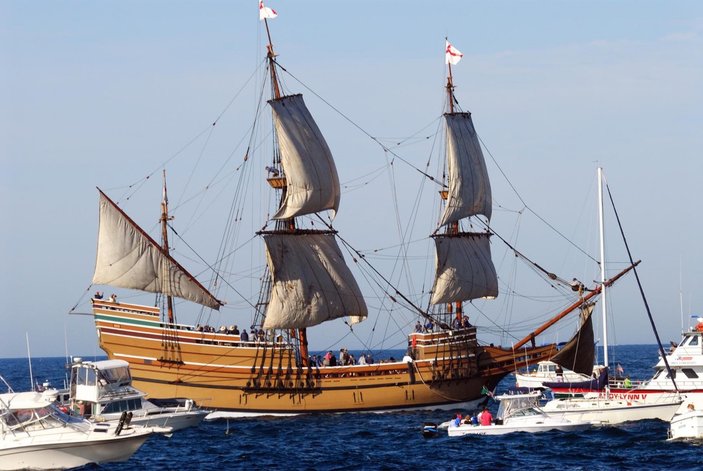
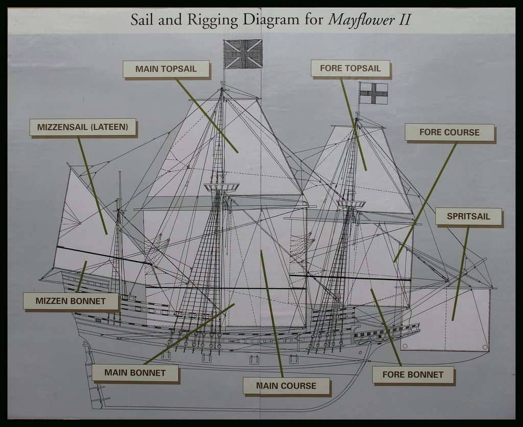
Good day Bill, Yes ,those pictures from my model/different stage af assembling... it is not yet completed, almost 95% done ... :))) planned to complete it this my vacation... hope so ! :))) Thank You very much for your attention to my experiments with rigging :))) For rigging Mayflower,... why not use original rigging plan of Mayflower replica straight? There are a few detailed rigging diagrams posted above, and from Mayflower original site as well... lets say this is standart rigging aarrangements for the ships of that period...You could also use rigging plans of GOLDEN HIND as well, which also were posted recently in nearest builds... In the book A.Baker about Mayflower replica which I mentioned early You could found detailed description of all standing and running rigging ropes , how they rigged and secured... You could load this book for private use frm here https://cloud.mail.ru/public/MpaE/CZdnEmv6e
-
Good day Jonathan, Jeff Regarding thickness of the rigging - this is good input from Jeff about rigging and sources!... I've head ,that there is sence, for the models, to increase calculated diameters of the model rigging in 30% approx , which gives more estetical vew of the rigging... I think it (30% increase)will be more suitable for 16-17 rigging than for the 19-20 centuries rigging... sometimes using exactly calculated rigging diameters gives visual effect of too thiny rigging... however Jeff mentioned such issue in his post I did my rigging roughly follow this rules ,first I made my rigging plans for all standing and running rigging but later on I had to made some simlifications due to I started my rigging using ordinary conventional treads I've found in the nearest market(not all sizes I neede were available)😕.. I used same diameters for fore- fore top and main-main tops shrouds but already different ,as calculated, for fore stays-for main stays and partly of top stays I used already self made ropes of right sizes... *CA clue - Jonathan, I mentioned that it must be CA gel clue , it is thick in consistency and stays on surface when applied in total differently than liquid CA clue...this type of CA clue is conventional type,it usualy sells in the same place where liquid CA sells... type of clue "GEL" indicated on the package as a rule *liquid CA better to use in some places where You want to make threads to keep desired shape - strait or curved imitating gravity force...I used very liquid type of CA for crowfeets when need to keep them all in strait lines (mizzen lifts,etc) in this case better apply liquid CA on unpainted treads and paint them after CA became dry * as I know ,CA not so good for cotton treads there are a few pictures where I used CA liquid type - for coating crowfoots of mizzen lifts and martnets... for other places to fix rigging more handy to use CA gel

-
One time I opened my box with this model and...closed... realised I need to read too much books , before start build it... "intimidating"- new english word for me !!! :))) , Yes - fully agree, it is very complicated kit...and as I know,very interesting in assembling.... have You seen this build ? https://www.segelschiffsmodellbau.com/t125f165-to-Victory-and-beyond.html
- 265 replies
-
- 2
-
-
- Golden Hind
- Airfix
- (and 1 more)
-
This is Great kit for building detailed plastic model of the Victory!!! :))) I like it very much!
- 265 replies
-
- 1
-
-
- Golden Hind
- Airfix
- (and 1 more)
-
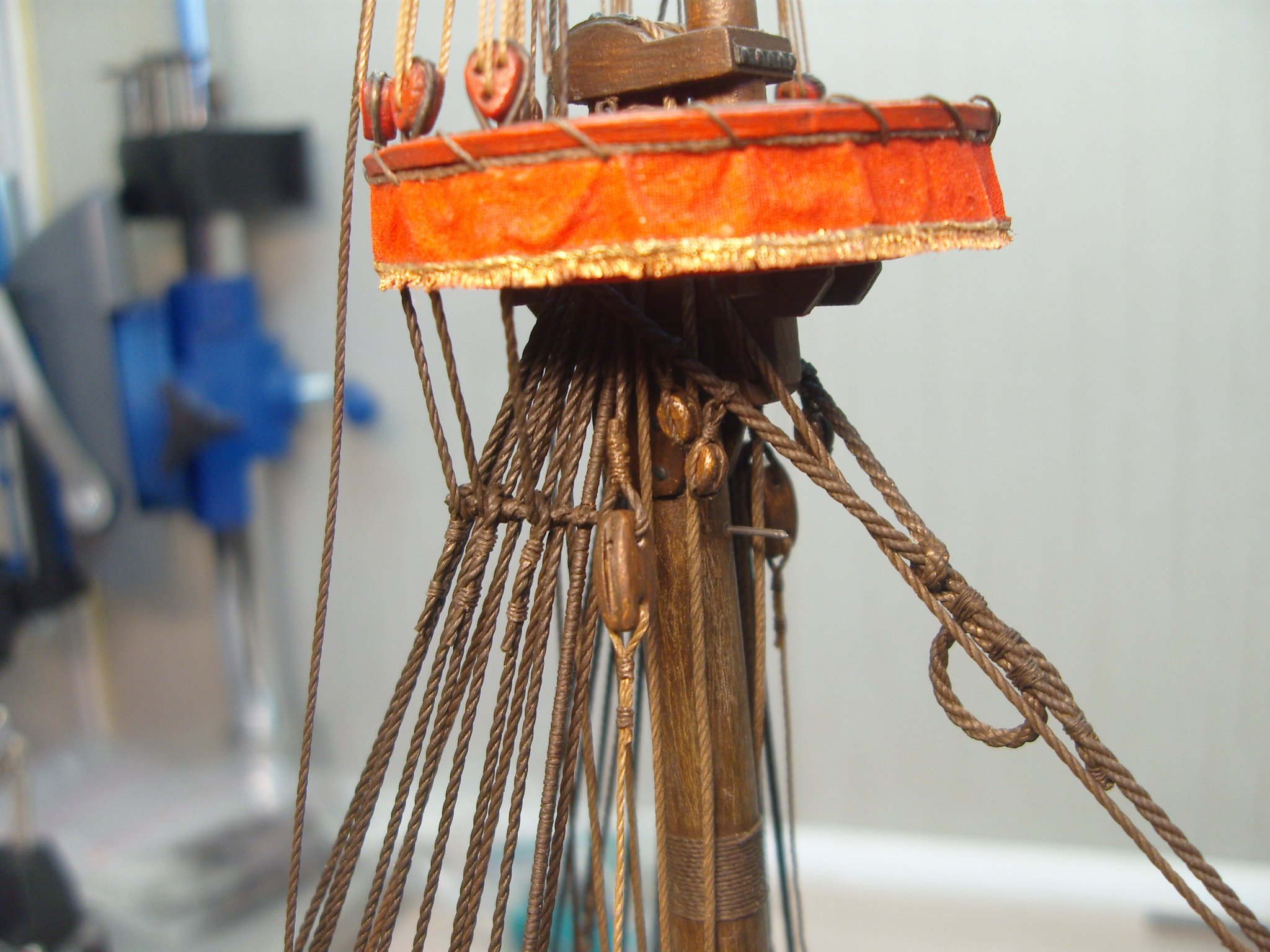
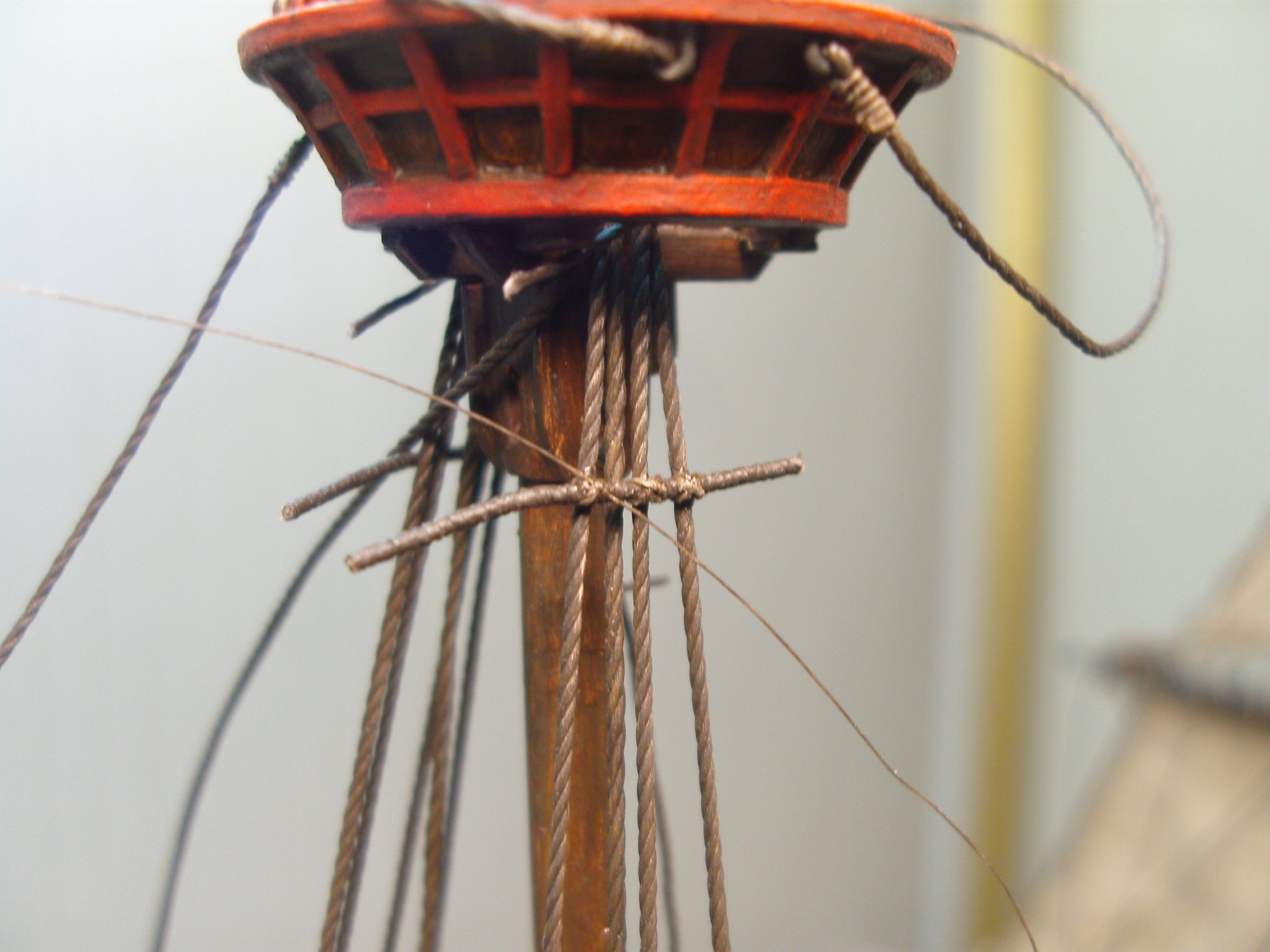
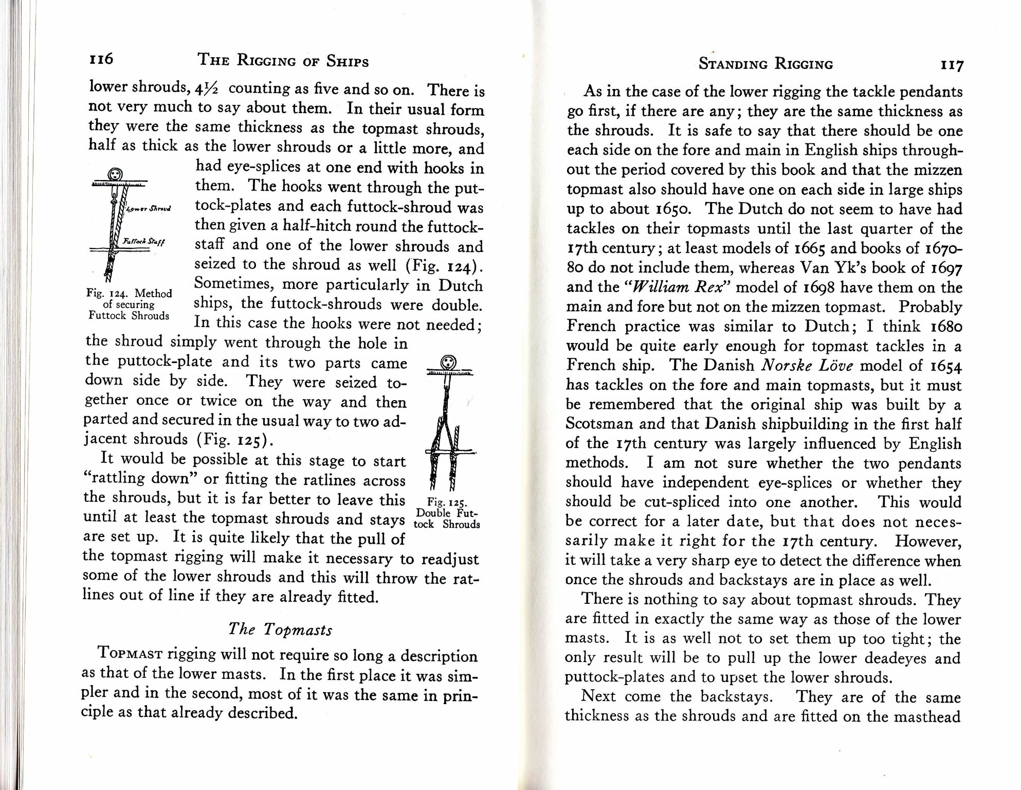
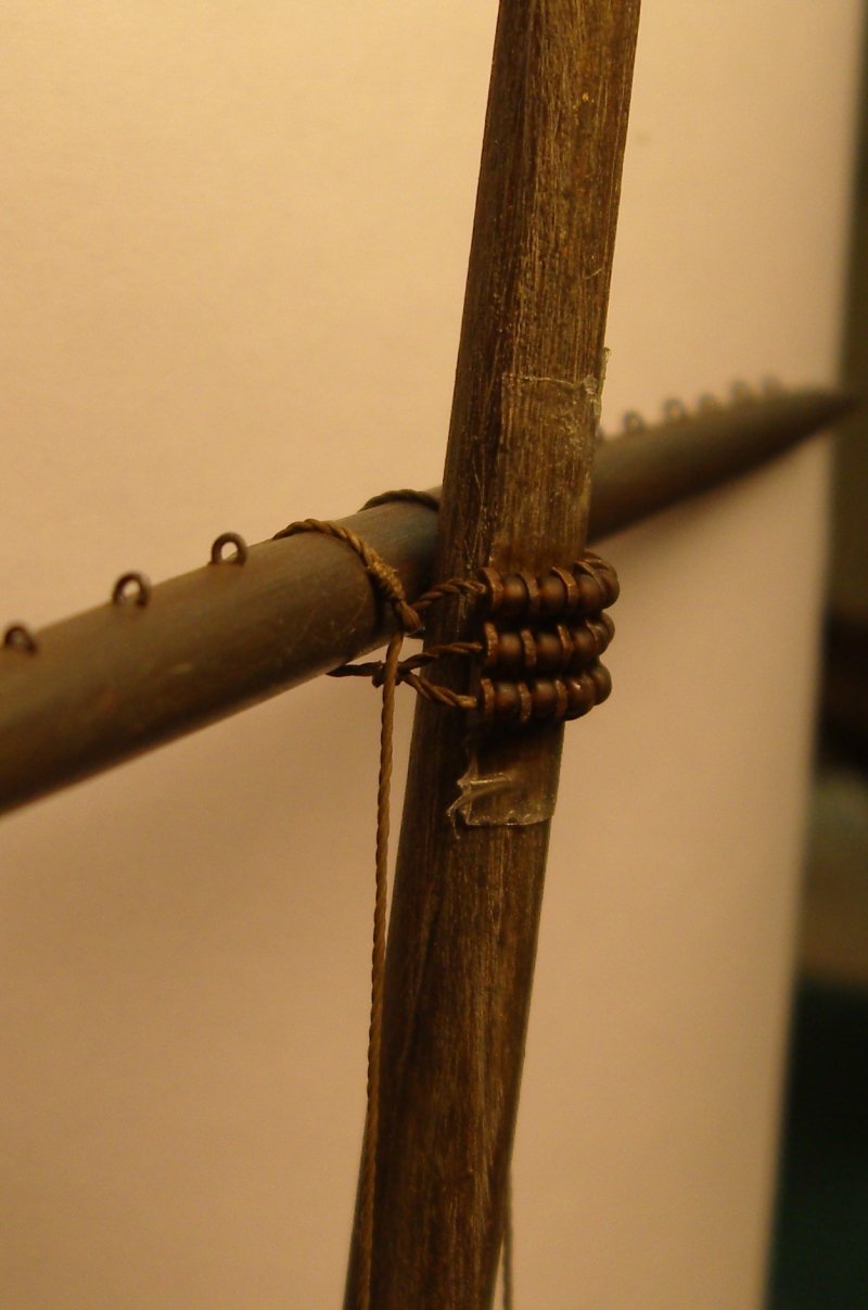
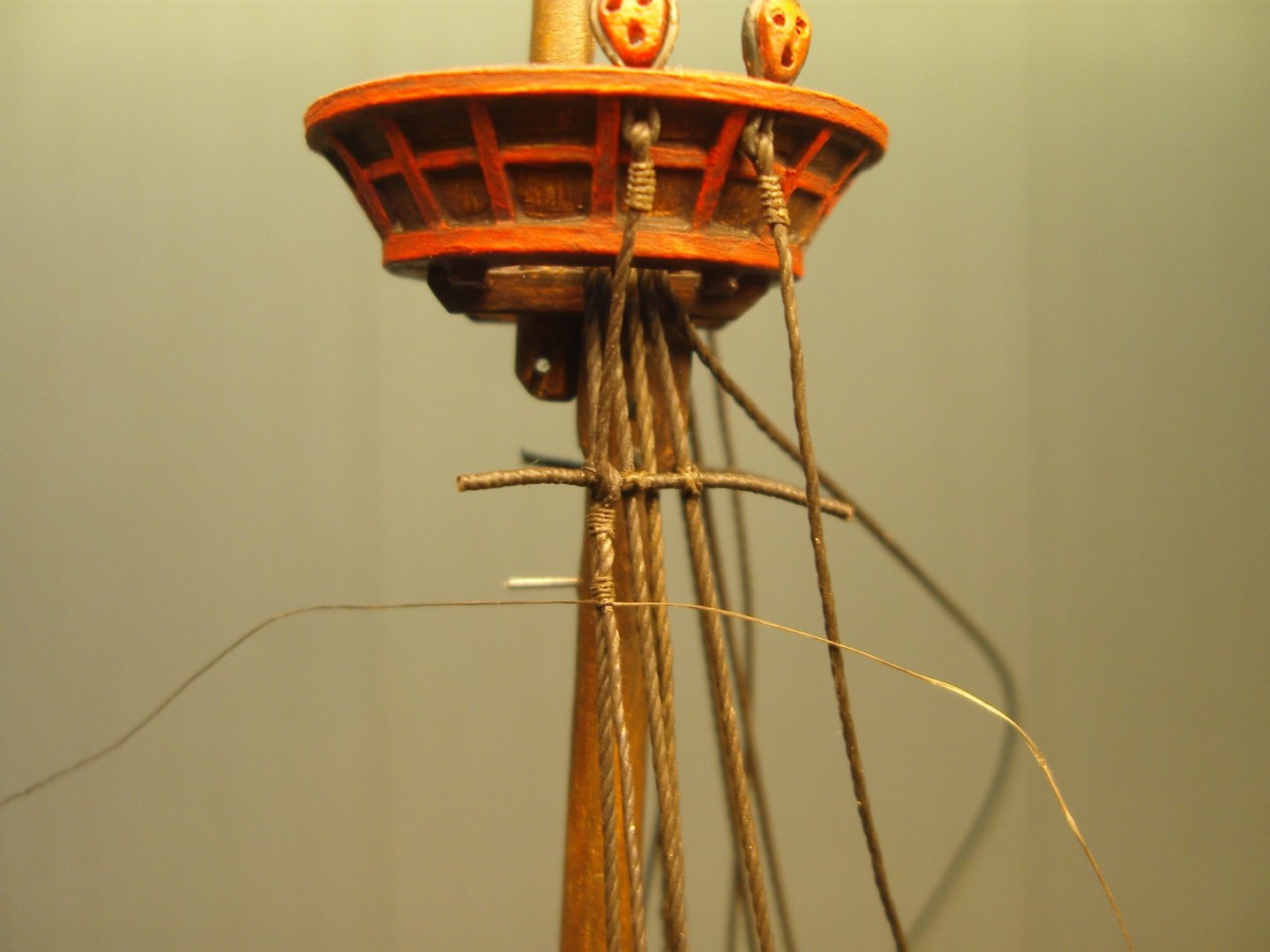
Good day Jonathan, I understood now, it is the size ... when futtock shroud passes around staff...! When I look again and again on the foto with your futtock shrouds , for me it is hard to imagine than there will be issue with the "size"... Your Diameter of the futtock shrouds is approx 2 times less than main shrouds,which is correct, in this respect there is no sence to reduce it... I doubt a little bit that making fake loop around the staff instead of normal knob will look more estetically... making fake loop we need later on to hide somehow cutted end of the treads, quite difficult task... *Have small request, as experiment, if possible, - to connect one futtock- shroud to puttock plate(temporary), pass running end of futtock shroud round futtock staff giving half -hitch(in such way as it is shown on the pictures from Anderson or Mondfeld books) , suspend some weight to the free end, don't yet apply any seizing yet , and show us two pictures -from distance and close vew ,how it will looks like half-hitch from futtock shroud on the futtock-staff?, just interesting to evaluate visualy result when it will pass around staff ? *I saw You mentioned that you use PVA clue to fix rigging treads... I could reccomend to use instant CA clue gel, not liquid CA!... this gives immediate result as soon as you apply small drop of CA (could use tooth pick for application) to the treads and pressing a little place of contact during 2-3 secs by tweezers. CA gel don't discolorate treades, stay at place of application,could easy painted and work fast - by my experience it works much much handy than PVA clue... *don't You use magnifier glasses? I can't work without them and very powerfull lights for working place when making small rigging seizing ...
-
Good day Jonathan, I see... interesting ,what was wrong for your eyes when You try to arrange futtock shrouds around futtock stuff? Too thick knots when f-shrouds run around futtock stuff or smthg else? I/m asking becouse scale of your model quite big(my scale was 1:100)...and I expected in such scale treads should run smooth without negative visual effect...that was the reason when I asked why You did them in such way... I also had the same issue with my model futtock shrouds during installation, but finaly more or less I've managed it...in this way(may be this info will be usefull): *thickness futtock shrouds should be the same as respective topmast shrouds... *during installation we could use unpainted tread, it will be softer and easy for manipulation, and to paint it after installation *we could use tweezers to assist in forming knots when futtock shroud goes /passes around futtock staff *during assembling process,temporary ,we could use some small weight suspended to the fyttock shrouds end to obtain ness-ry shrouds tension(when we are busy with forming knots around futtock staff better have some weight for constant tension) ,and remove it after installation


-
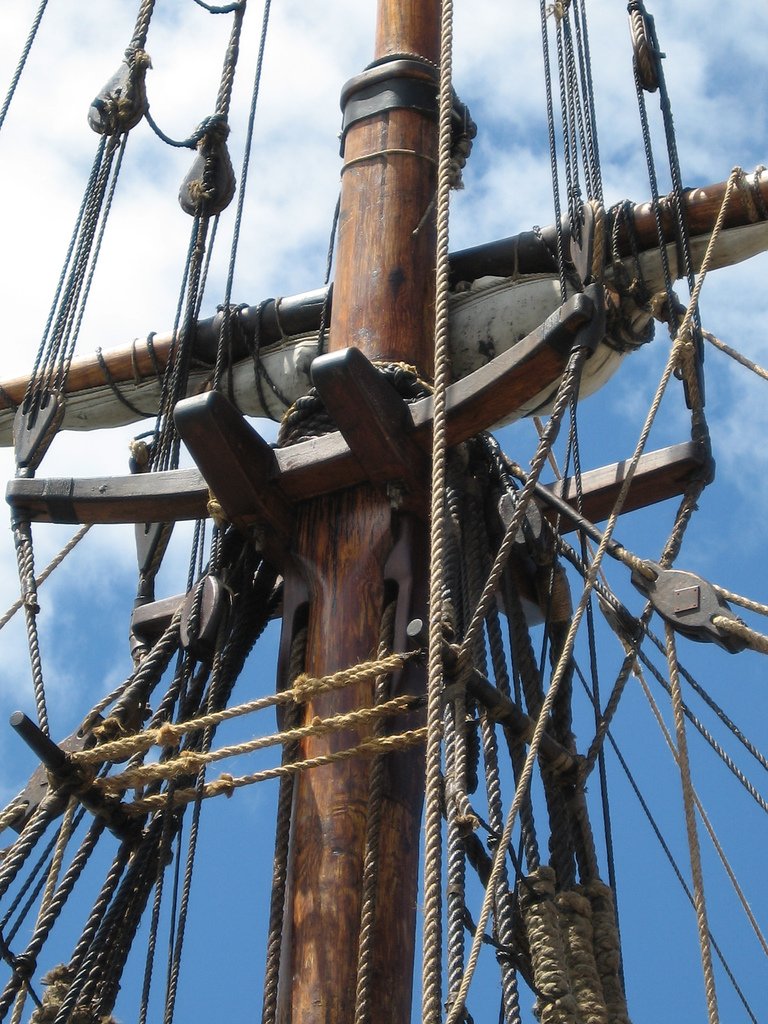
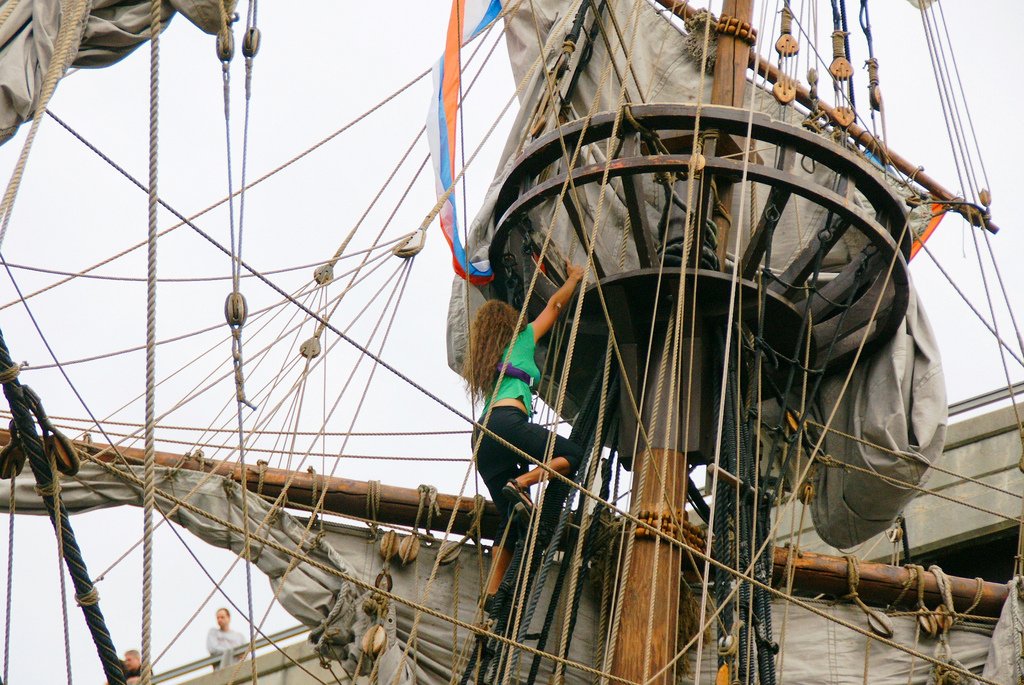
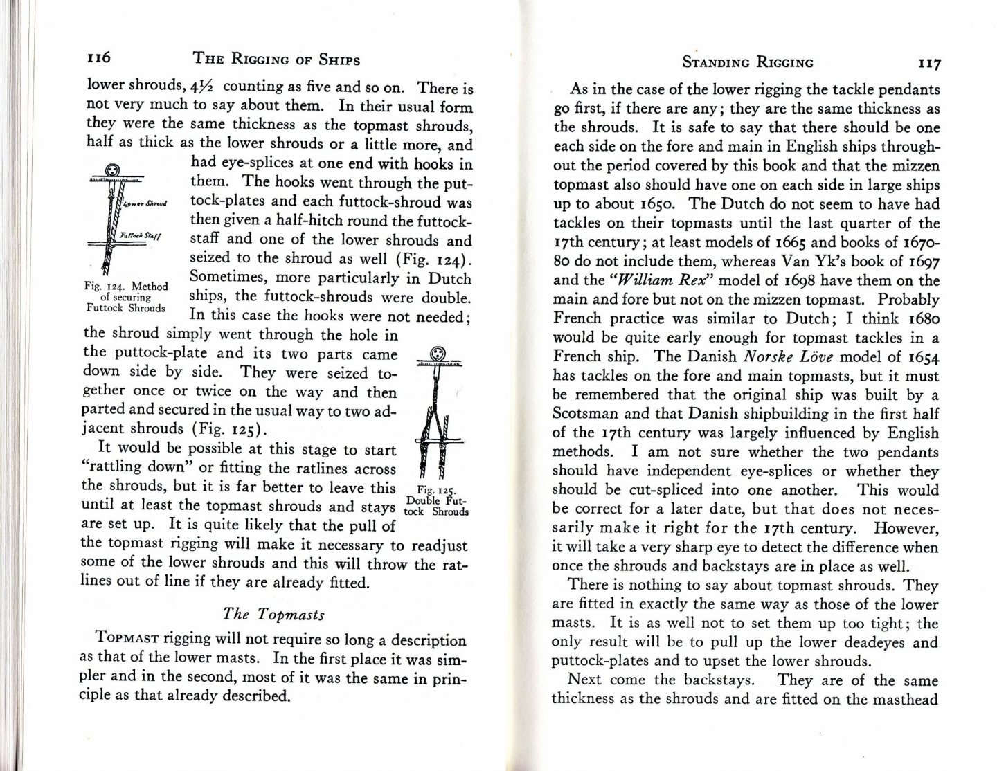
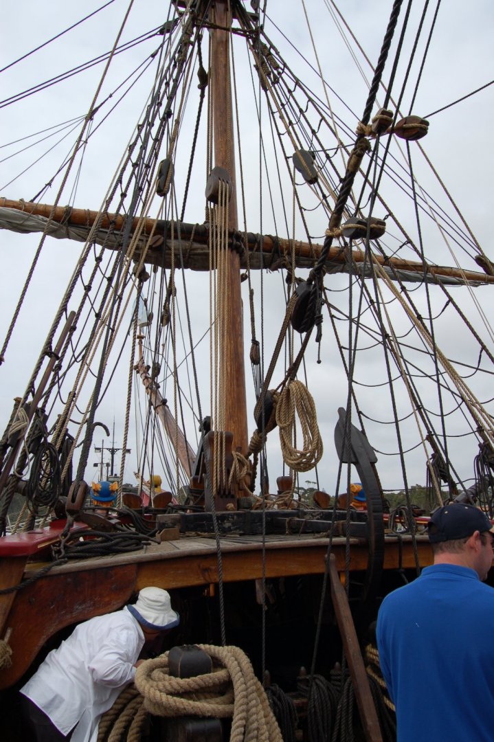
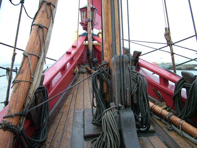
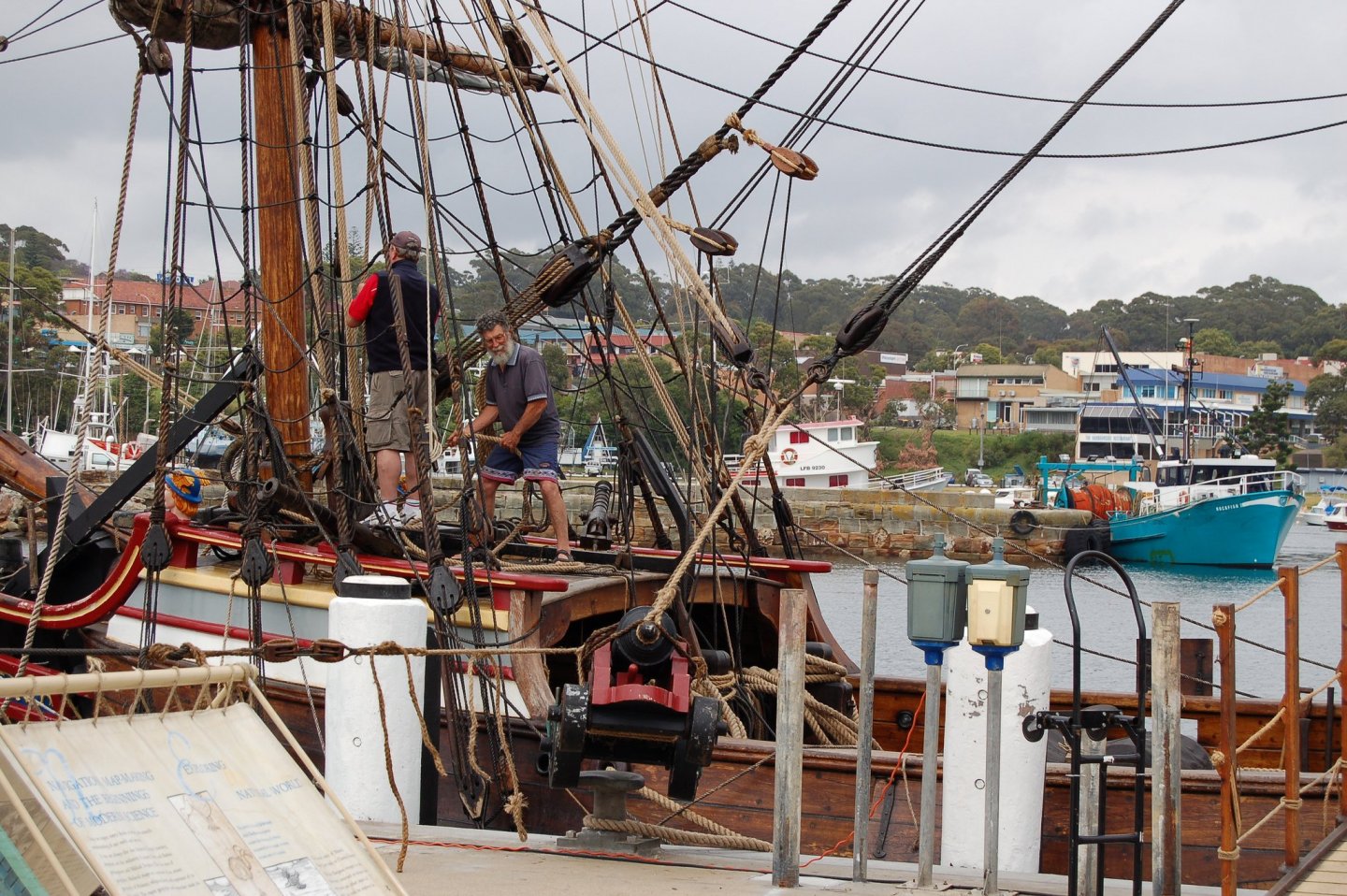
Good day Jonathan, Your rigging looks pretty good! This wooden bar which You installed - it is futtock-staff , it looks very nice !!! . As a rule Lower ends of futtock-shrouds need to be taken round the futtock-staff... there you did it a little bit wrong... There is very good book about 16-17 rigging written by R.C. Anderson "The rigging of the ships in the days of the spritsail topmast 1600-1720" where You can found answers practicaly about all aspects of 17 century riging including end of 16 th century... I have some pictures where we could see futtock -shrouds arrangements... there are scans from Anderson and Mondfeld(Vasa) books and foto of modern but very accurate replica of Duyfken and Half Moon

-
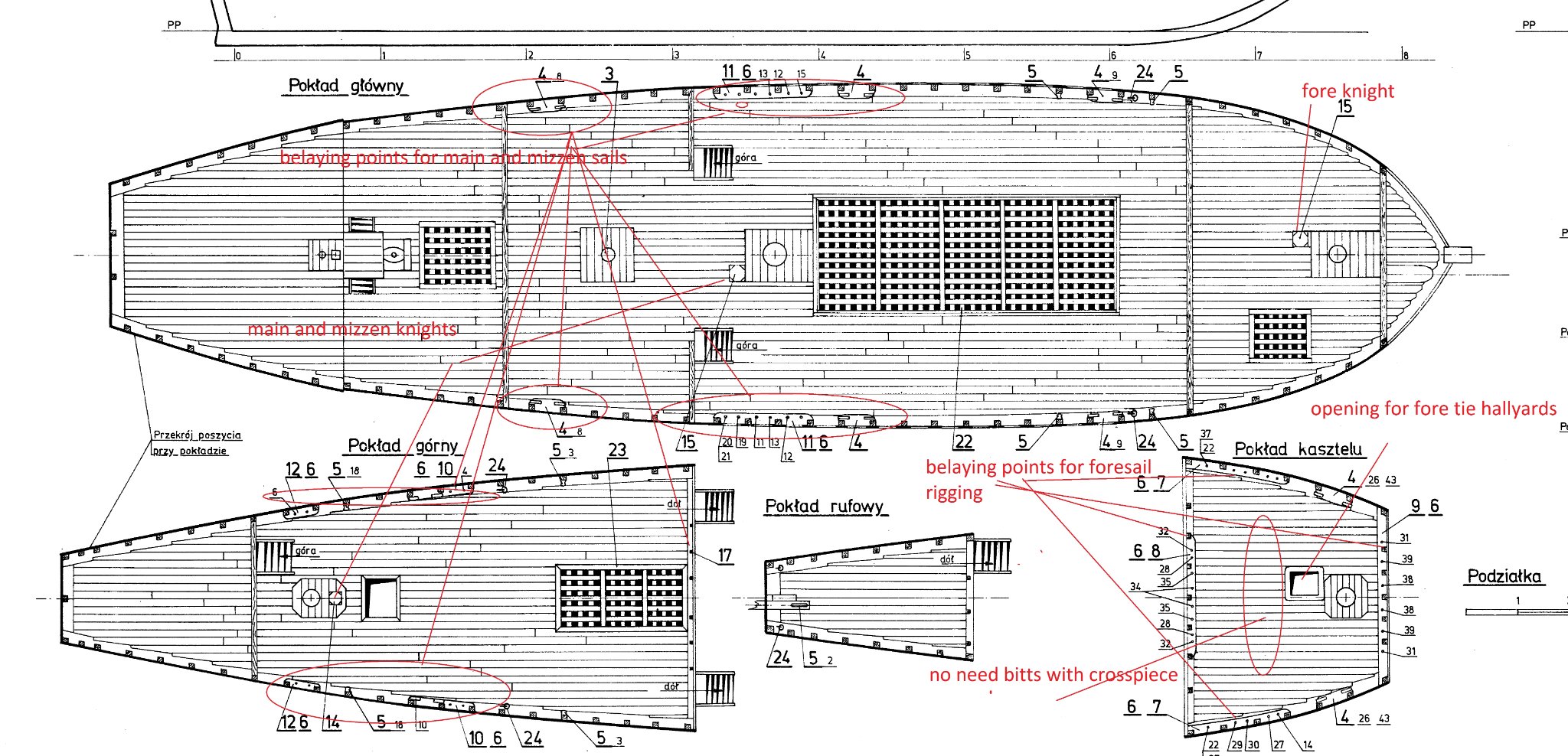
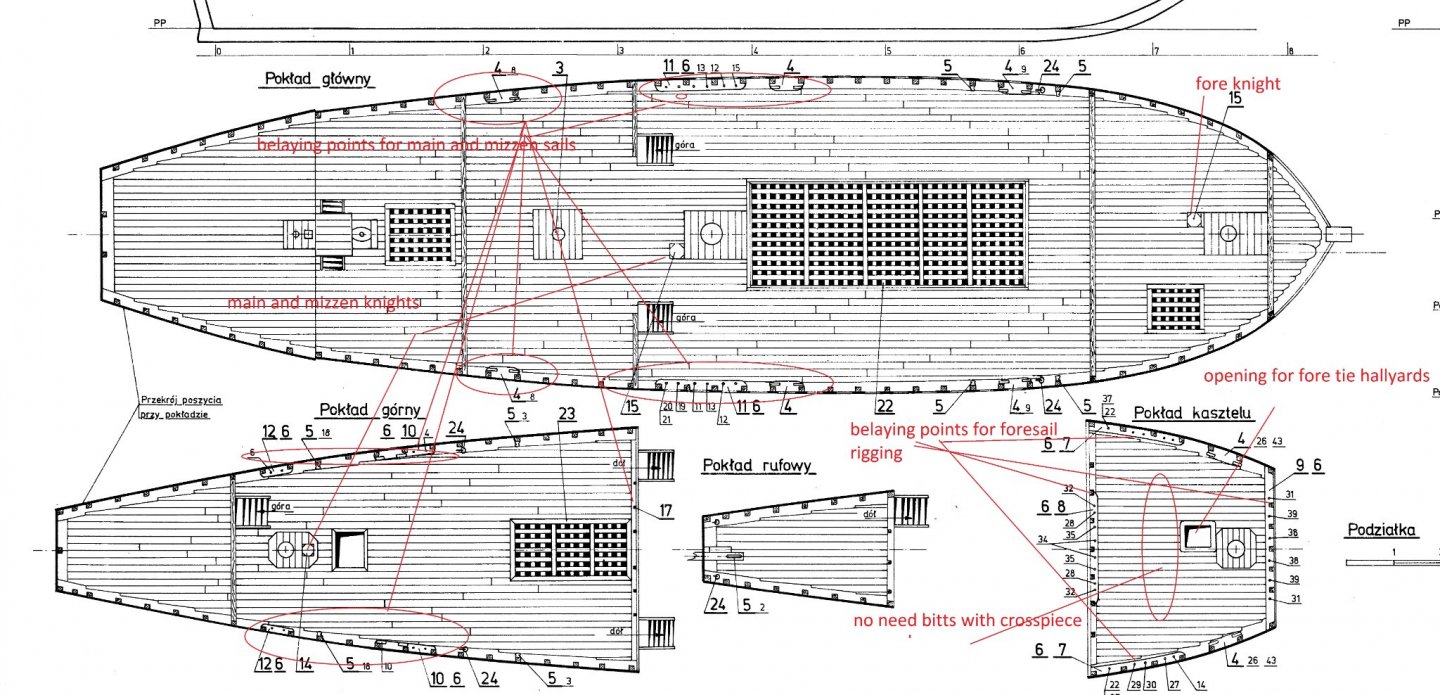
there is suggestions for rigging arrangements... please check also positions ,sizes of your fore,main,and mizzen knights ... biggest should be main knight, and they shoul have at least 3 sheeves in the knight for arranging tie hallyards and one more sheeve for top rope ... I saw on the pictures which You posted , that all your knights have same size...and only one hole in??? there shold be something like this \Duyfken replica
-
there are some quality Mayflower drwngs(polish and german found them somewhere in internet fields) You could use as reference in case some modification need to be made , in particulars, there some modifications/adding elements (which missed in kit) need to be made on your stem and beakhead https://cloud.mail.ru/public/Vqn7/UW6PYR6ei https://cloud.mail.ru/public/8gtE/UnD1EaEJh

-
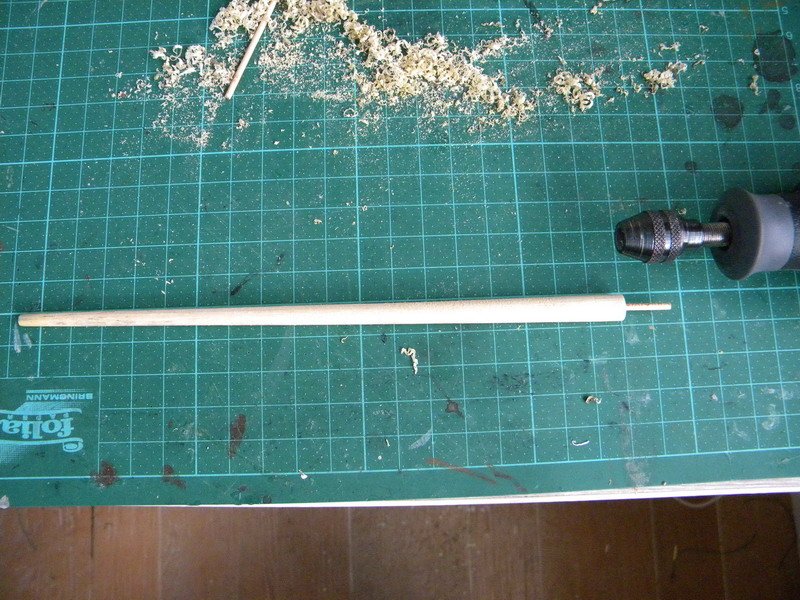
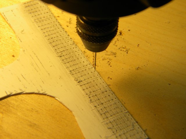
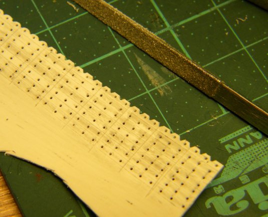
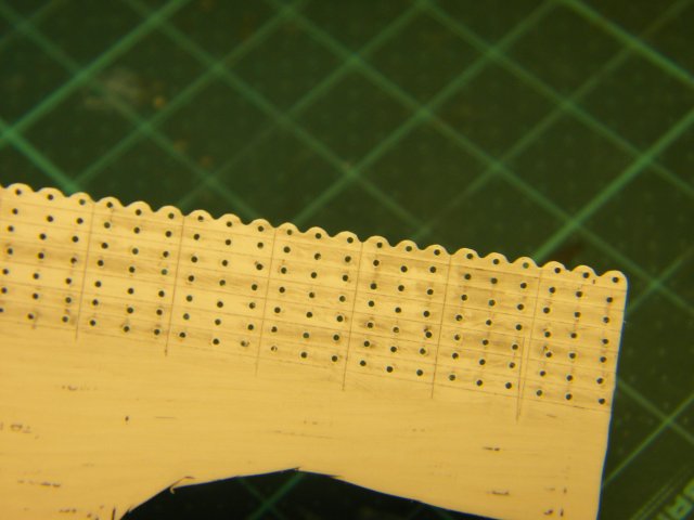
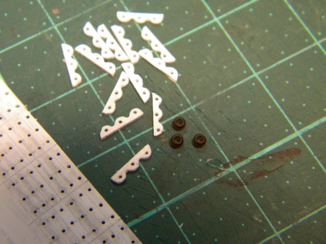
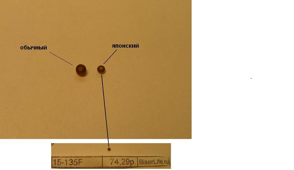
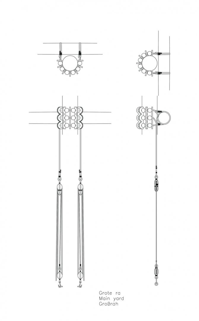
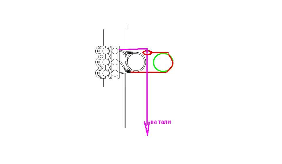
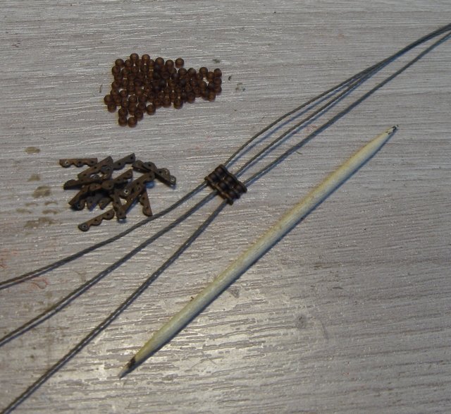
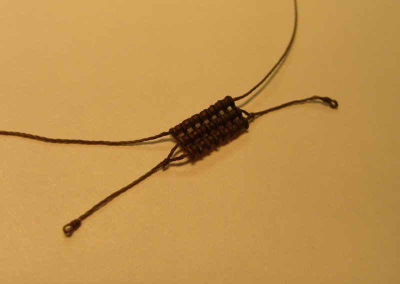
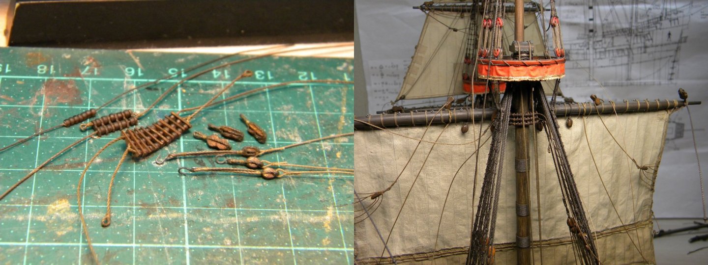
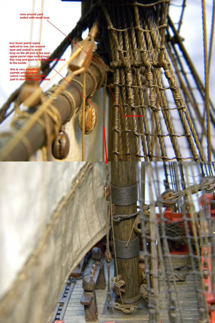
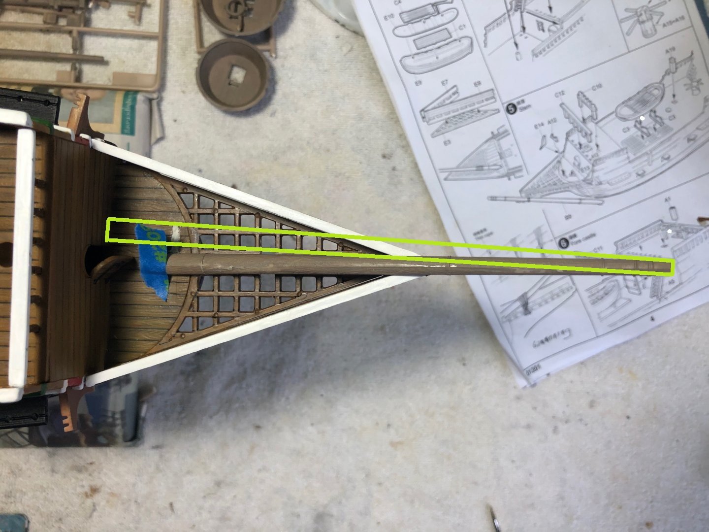
Good day Bill, If I would be You , I will prefer to move it in more acurate position :))) ... Franckly speaking I used to do countless rearrangements and modification of rigging in my model , often a few times changed one spar or rigging ,so already became not worry too much abt such issues... consider that old holes and damaged paints in plastic models always could be easily recovered with suitable fillers,piece of plastics and new paint...and will looks same as before :))) But If You don't want spend time for changing bowsprit position again, just leave it like that...anyway it will be better than kit's version. There is one point - You would better to check length of bowsprit / as already discussed recently in "Revenge build " if it is short, there will be not sufficient space for spritsail operation ... and maybe there is sence to make it from wood - I changed main for wood ,made it from artists brush handle , using my DREMEL and sand paper I made brush handle to desired form ,than painted it in the same color as other remaining plastic spars painted... the matter is (why need to make bowsprit from wood)- when You start rigging bowsprit will be quite loaded element , and if left it plastic there will be a big risk to bend it upward when You will rigging fore stays... parrels - I made them from waist plastic sheet (take it from some instant noodles used pakage box) and so called Japanise bisser , which is almost twice smaller in size than conventional bisser , and this size was very good in scale for my model 1:100 for your model You could use ordinary bisser for main sails and japanise bisser for topsails... there are a few pictures how I made my parrels ... and simplified diagram wich I made for parrel tackles arrangements to fix temporary parrels on the mast wnen making loop on the parrels rope I used two sides scotch


-
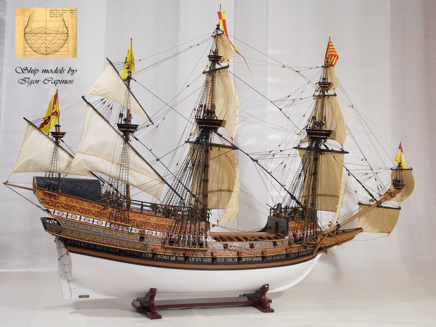
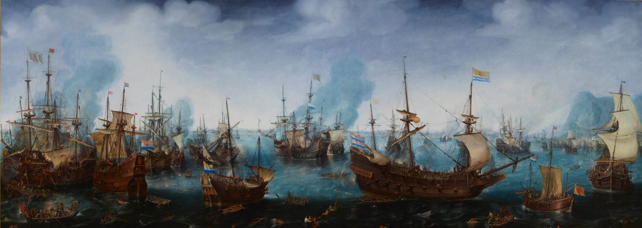
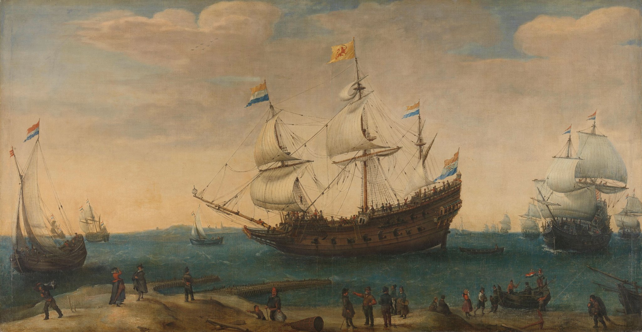
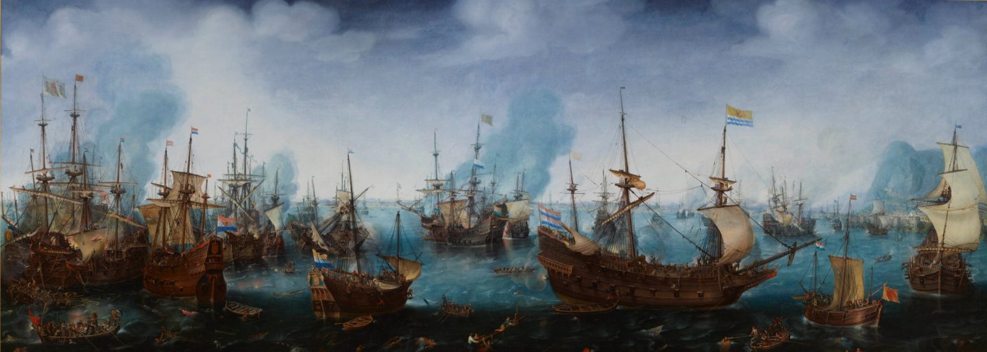
Good day Jeff, It will be interesting , upcoming sails making adventure !!! I've made main from percale cotton... I think kit's rigging plan is good , must be good! :))) and for more information ,if ness-ry ,we always have these very detailed historical paintings and R.C.Anderson book which gives us accurate description of each rope of standing and running rigging ... there is very interesting ,high level model of flemish galleon made by Igor Capinos, exelent source of various details could be seen ! http://sailmodel.ho.ua/galleon/index.htm

-
roughly say it should be same length as fore mast...
-
did You check the length of bowsprit... seems too short ?🙄

-
You asked how to secure yards to the mast - I used piece of steel wire to connect yard and mast - drilled small holes in both and fitted wire between yard and mast... when yard fitted at place this wire couldn't be seen... and additionally yards secured to the masts by parrels - I've made them in simplified form, just to show this part of rigging presents...

-
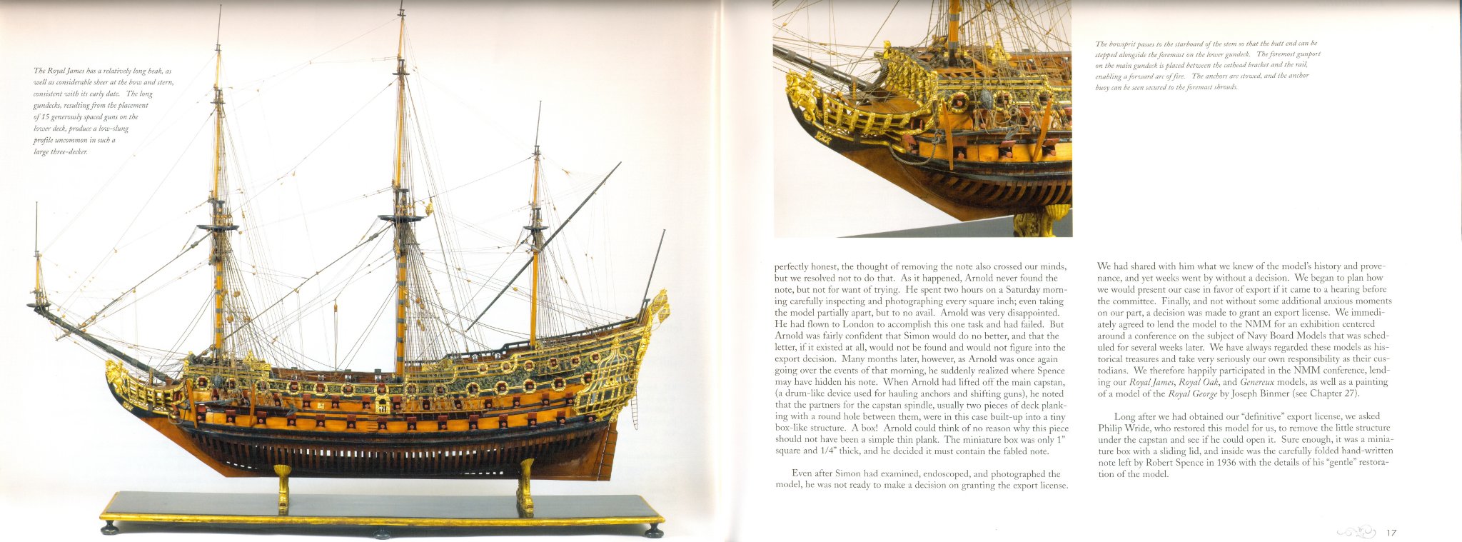
by the way, such positioning of the bowsprit - off the center line, but stepped alongside fore mast continue in use till the end of the 17 th century - look at the contemporary model of "Royal James 1671" and its bowsprit location

-
Good day Bill, By my opinion position of bowsprit looks much better now ... to avoid intensive modifications this position could be considered as final ! :))) But I meant something else in my previous post "... need to be stepped to the one side of the foremast and stem and secured in such way that it's tip lays on the center line of the hull...so there will be angle to the hull and bowsprit will not be parallel to center line..." but OK , maybe this position of the bowsprit will be not exactly hystorical accurate, but much better and more correctly than Trumpeter's proposal🙂 My sugestion was :
-
Good day Jeff, Oh yes! On your last posted picture bowsprit length looks quite proportional ! And spritsail yard position on this picture seems correct! Now I understood that the problem lies with the prototype on the box, but they did nessasary correction in the actual kit! Very good!!! I'm Sorry for that too intensive inputs regarding bowsprit length from my side :))) just was afraid to see model spoiled by unproportional rigs :))) Do You plan to fitt sails on your model? All the best!!!
-
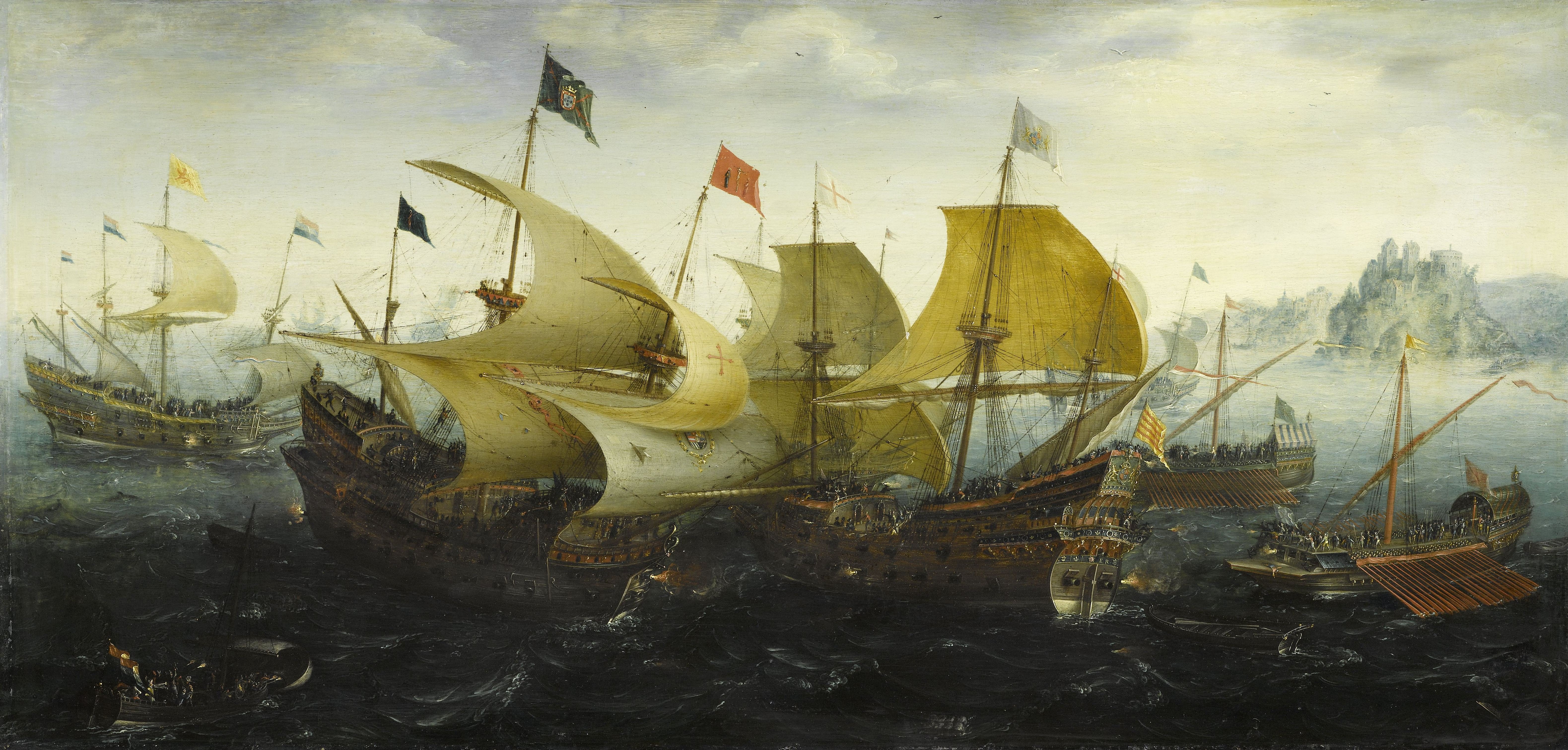
bowsprit position - there are a few contemporary pictures-look at the ships which are in front vews

-
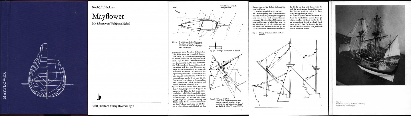
Good day Bill, I'm sure Trumpeter did something wrong here... as seems to me , they start it right, when positioned bowsprit stepped to the one side of the foremast , but after that they continued in wrong way when choosen such extreme angle for bowsprit ... bowshprit need to be stepped to the one side of the foremast and stem and secured in such way that it's tip lays on the center line of the hull...so there will be angle to the hull and bowsprit will not be parallel to center line, but this angle will be much less than Trumpeter did. There one more Trumpeter issue - location of the main hatch 🙄🤔!!! If in case with bowsprit I could understand more or less the way of their thinking, but in case with main hatch location I have no idea at all, why they placed it off the center line???🤔🤔🤔 This is only my thoughts, but not a call for starting scratch build😄 As I understood This model represents exact replica of Mayflower II, and there is very nice book devoted construction and building of this replica, this book written with his own hand by designer of MayflowerII replica... I think it will be very usefull to have such book under hand as source of all nessary information while You continue building your model of replica Mayflower II. In this book author gives description of functioning and sizes of all spars and rigging reproduced in replica, and also gives very interesting background of english shipbuilding in 16/begining 17 centuries...W.A.Baker The Mayflower and Other Colonial Vessels and another book devoted to building Mayflower model written by german author N.C.L.Hackney ... it is in german, but provided grafic material is very representative ... I have both of them in digital form, if You need them let me know by email I will send You links for downloading for private use...