


JSGerson
-
Posts
2,168 -
Joined
-
Last visited
Content Type
Profiles
Forums
Gallery
Events
Posts posted by JSGerson
-
-
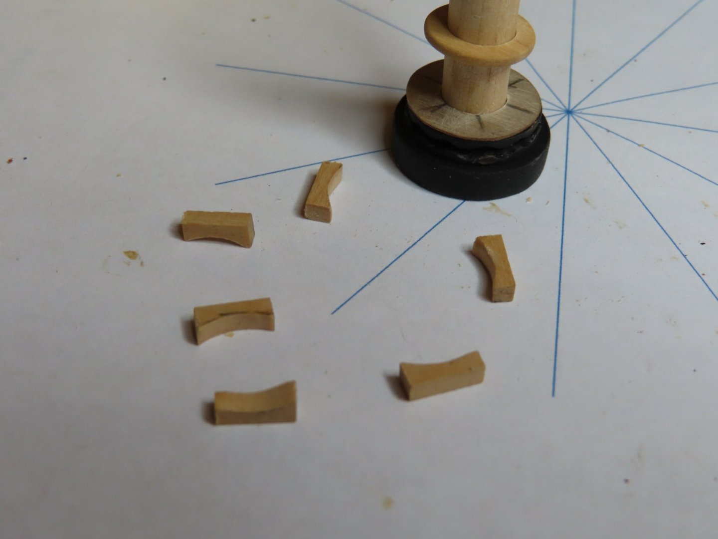
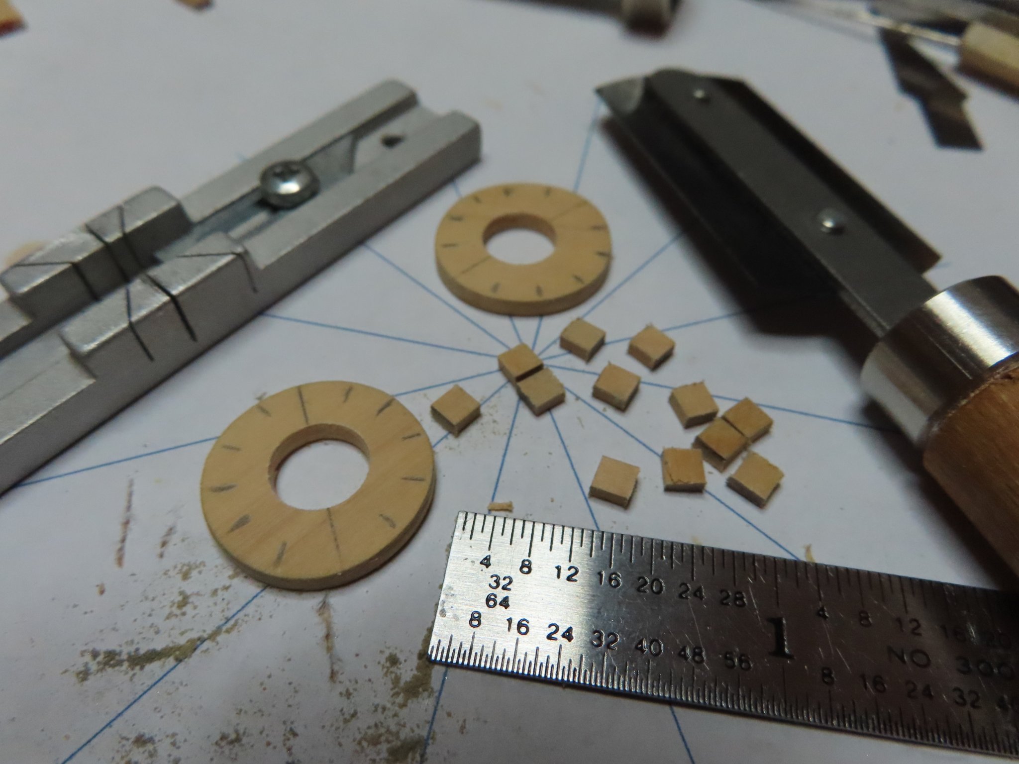
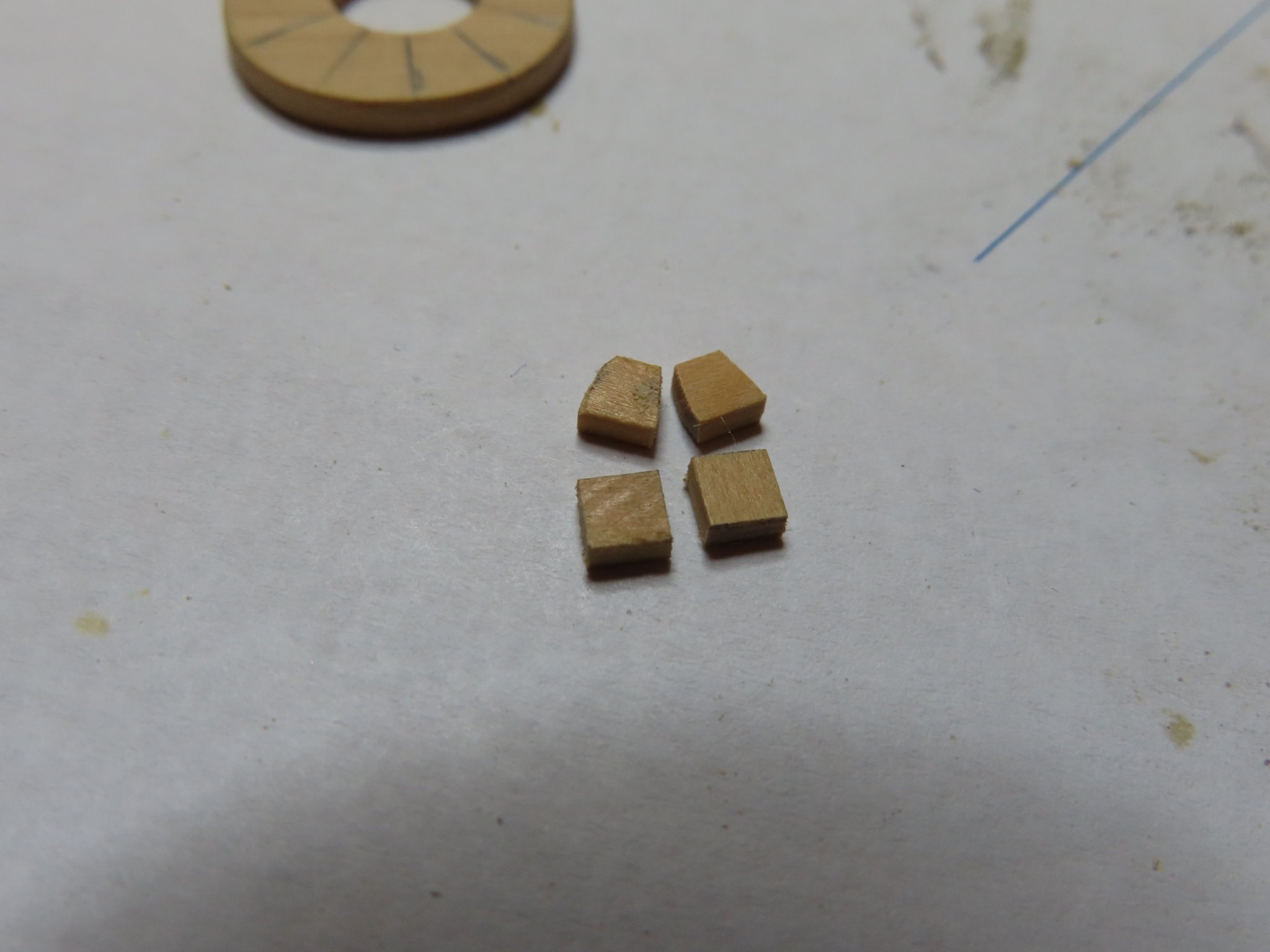
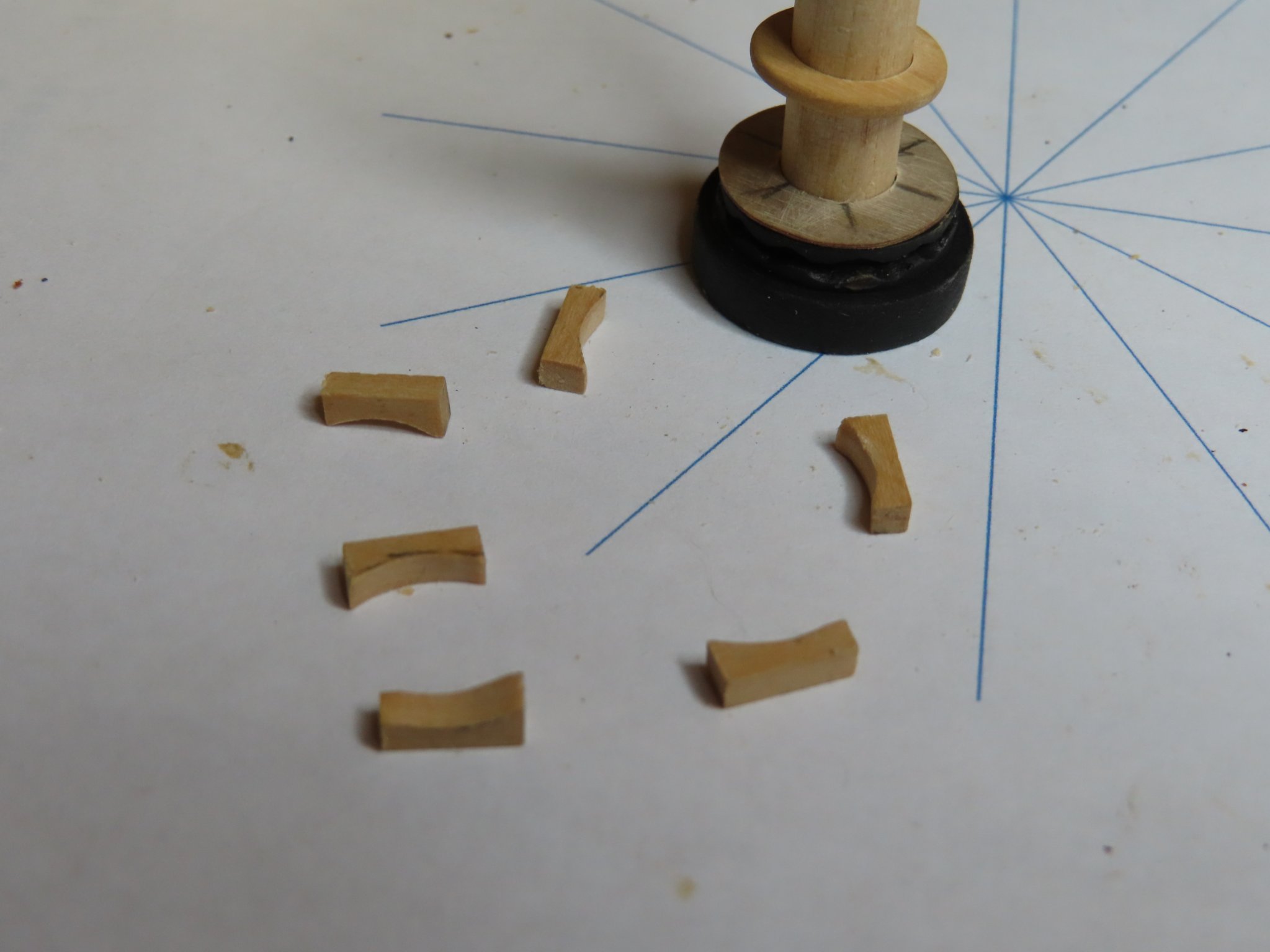
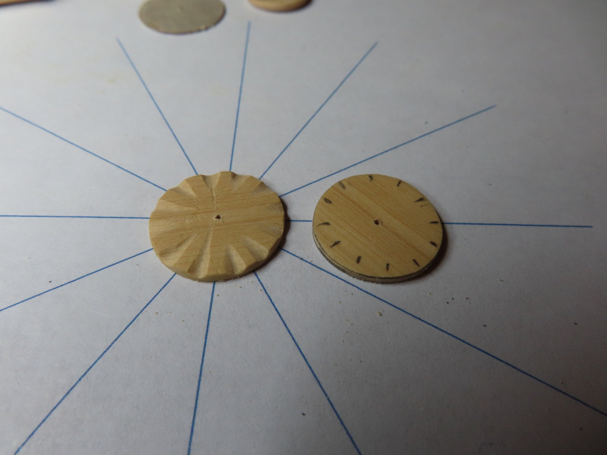
This next section had a false start. I started to construct the section where the capstan bars are inserted to rotate the capstan. (God, I wish I knew what the name of the various capstan sections are called). And I started to make these parts the in same manner I made the previous section with the whelps. I formed two discs and drilled out the centers. In lieu of whelps I started to make the pieces in between the capstan bar holes. These worked out to be twelve 1/8” x 1/8” x 1/16” pieces which I quickly realized I had to taper into a trapezoid shape to make them fit around the ring to leave a proper opening for the bars. It just became too much fiddley work. A quiver of a fingers, or an ill aimed breath would set the tiny piece out of alignment during the dry fit. I didn’t fight it and immediately tried another solution, which I think was much easier and had better results.

-
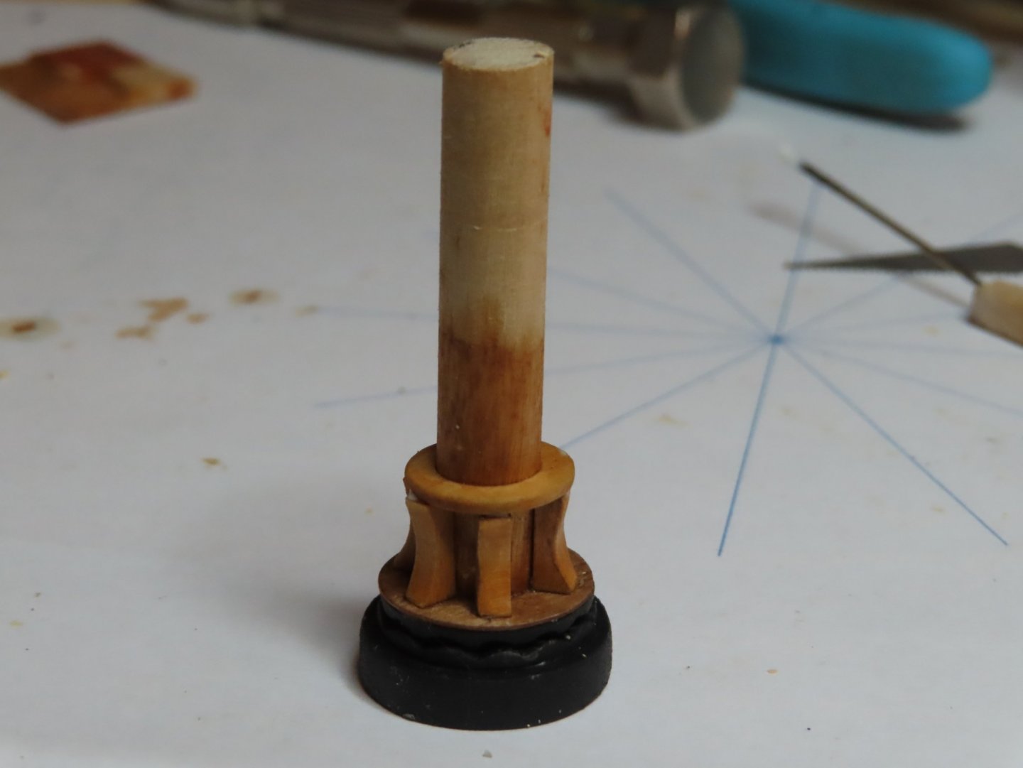
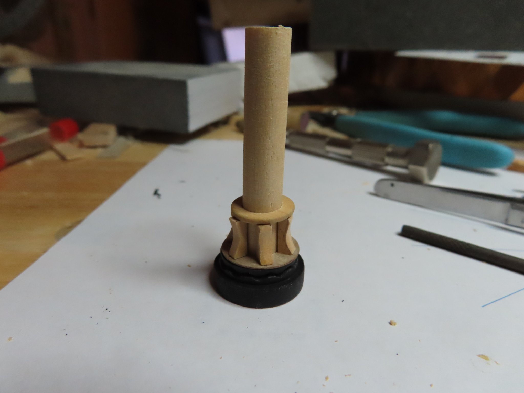
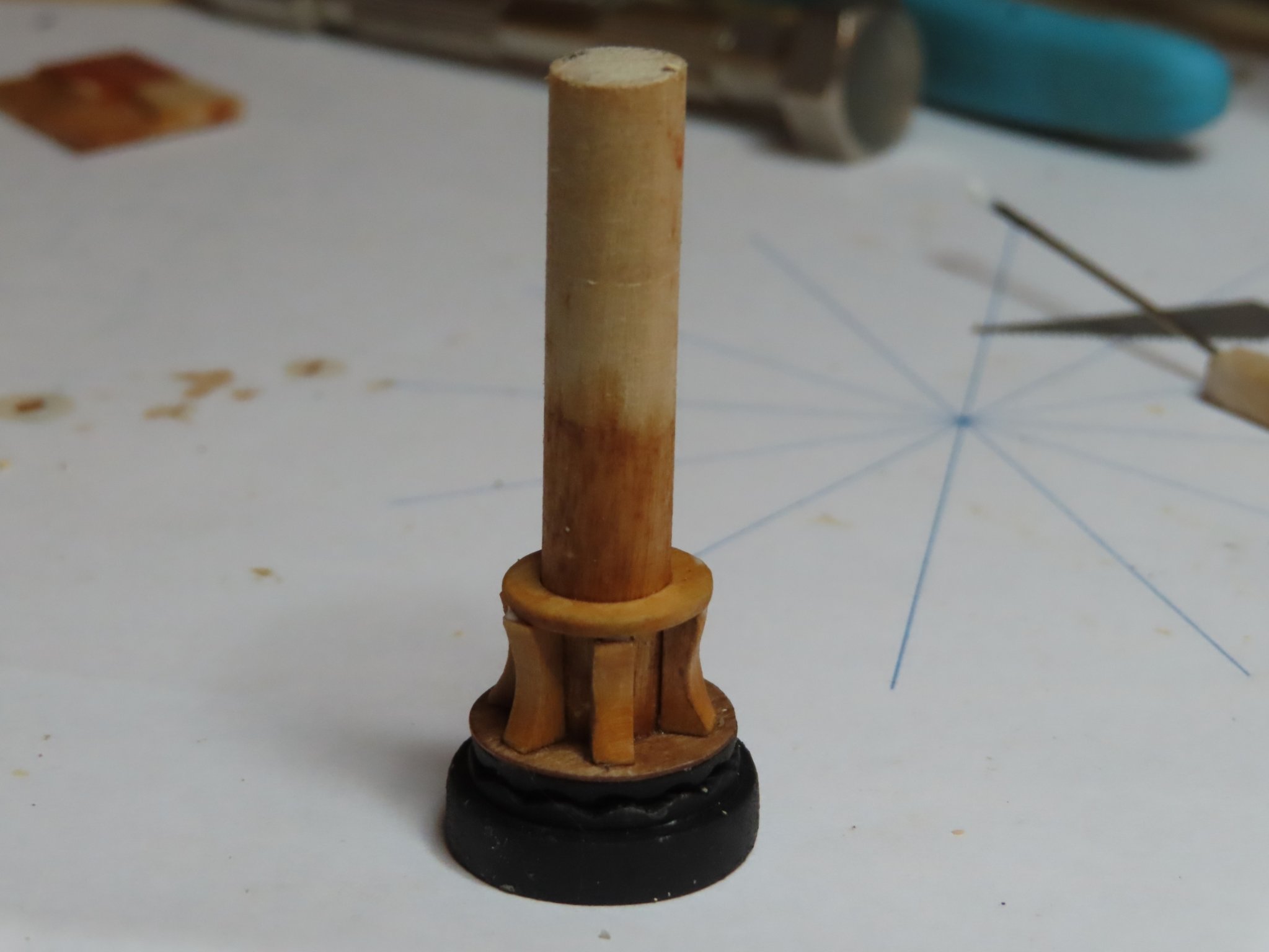
The base was painted black so what little detail I added here for the chain notches has vanished. This was expected and was the reason I did not add any other detail. Next, I carved the whelps using a Dremel tool and files. The upper support ring was fabricated just like the previous discs I made for the base. The whelps, the upper- and lower-disc support rings, and the dowel were stained with Minwax Wood Finish Golden Pecan 245. They all glued into place.

-
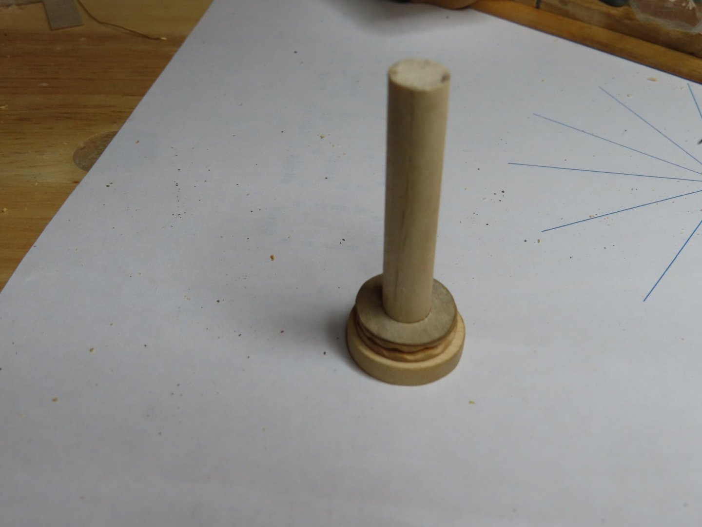
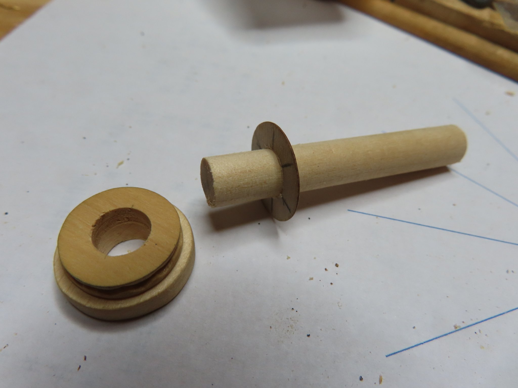
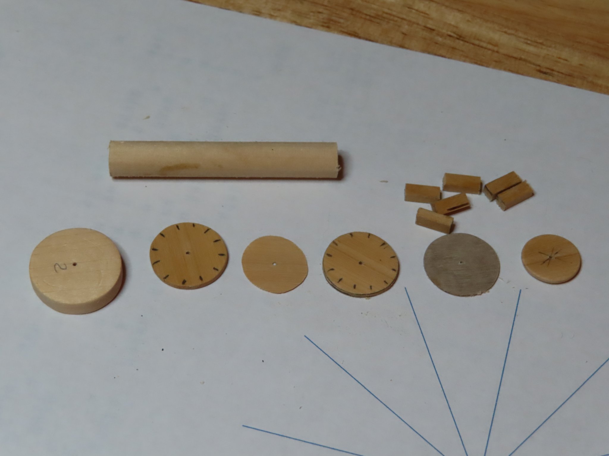
You may have noticed that all the disc parts have a small hole drilled in their centers. This used to align the disc parts with a pin when they were glued together. It then becomes the starter hole for a series of progressive larger drillings to widen the opening to 5/16” to accommodate the dowel. The center hole was drilled after the discs were glued because the assembly would be a solid piece and not subject to breakage during the drilling process. It also ensures total alignment of all the openings. In the images below, the base is drilled, and the dowel has the first support disc (1/64” plywood) for the whelps. The dowel was inserted for a dry fit. The dowel has not been cut to its final length at this point.

-
The capstan has an area for a chain. (not certain how this is supposed to work) I notched out two discs. The two discs are stacked on top of each other with the notches facing each other and a separator disc in between. That assembly is placed on top first base disc.


-
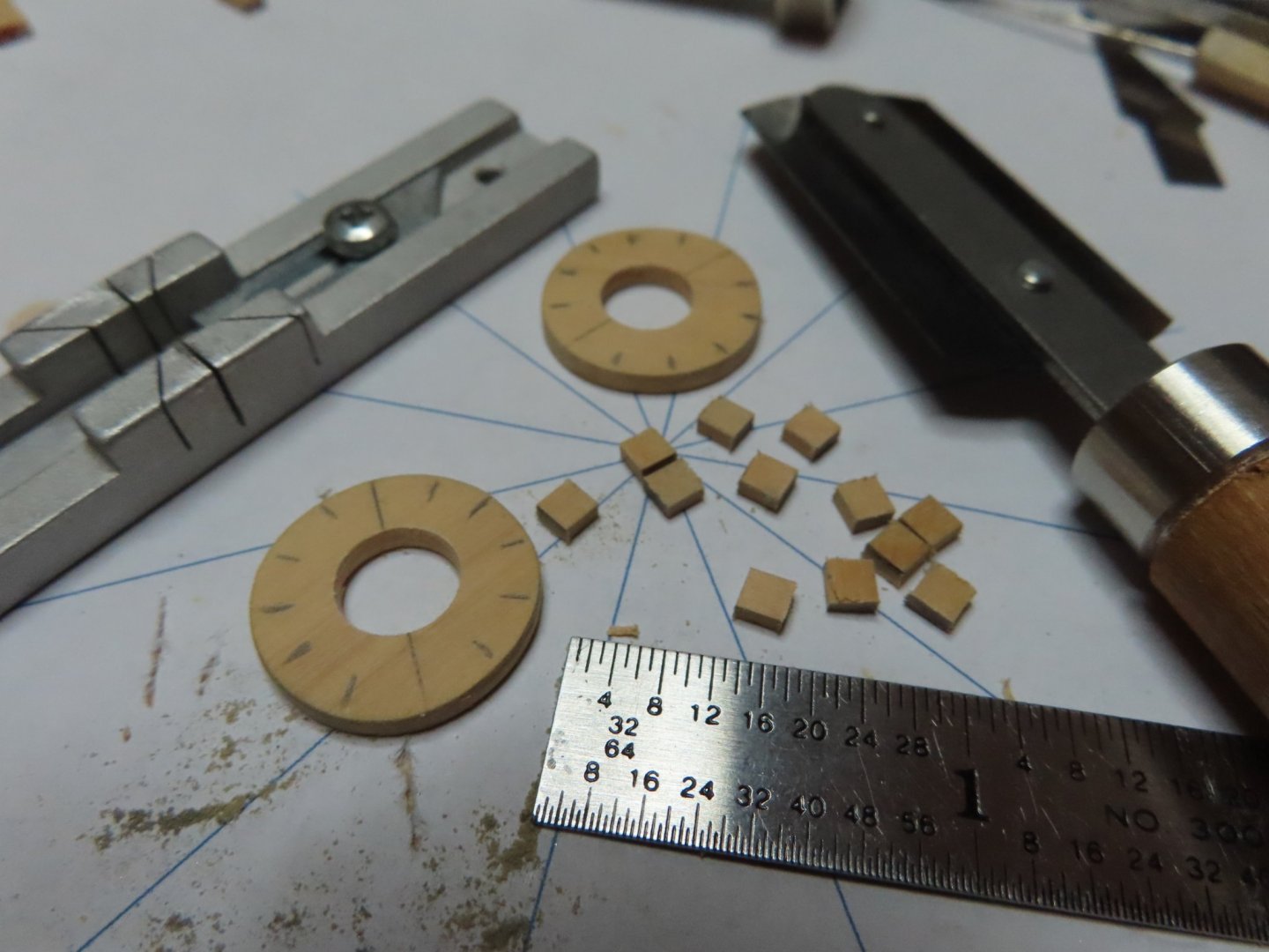
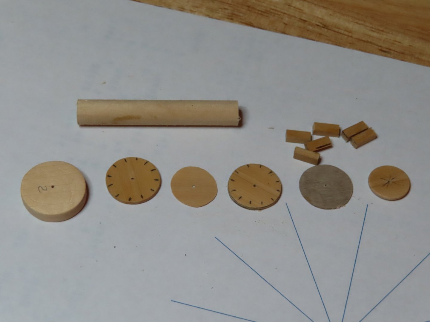
I did this for all the dimensions I thought necessary. And yes, I did get lost and confused in the computations and had to constantly check and recheck my math. Once I had my dimensions, I could then figure out what size stock wood I would need. In this case, because there are a lot of small intricate parts, I chose boxwood for its ability to hold a crisp edge which was essential for all the small intricate parts. Normally if the wood were to be painted, I would have chosen basswood. No point in using the good stuff if its going to be covered in paint. In some cases, I used 1/64” plywood for its ability not to split.
In the image below, the first four disc parts on the left will become the capstan base The remaining disc pieces will support the six whelps when attached to the shaft. They were all cut from sheet stock and sanded and filed to shape. The shaft is a 5/16” dia. dowel.
- Elijah, Ryland Craze, J11 and 1 other
-
 4
4
-
Gun Deck Capstan
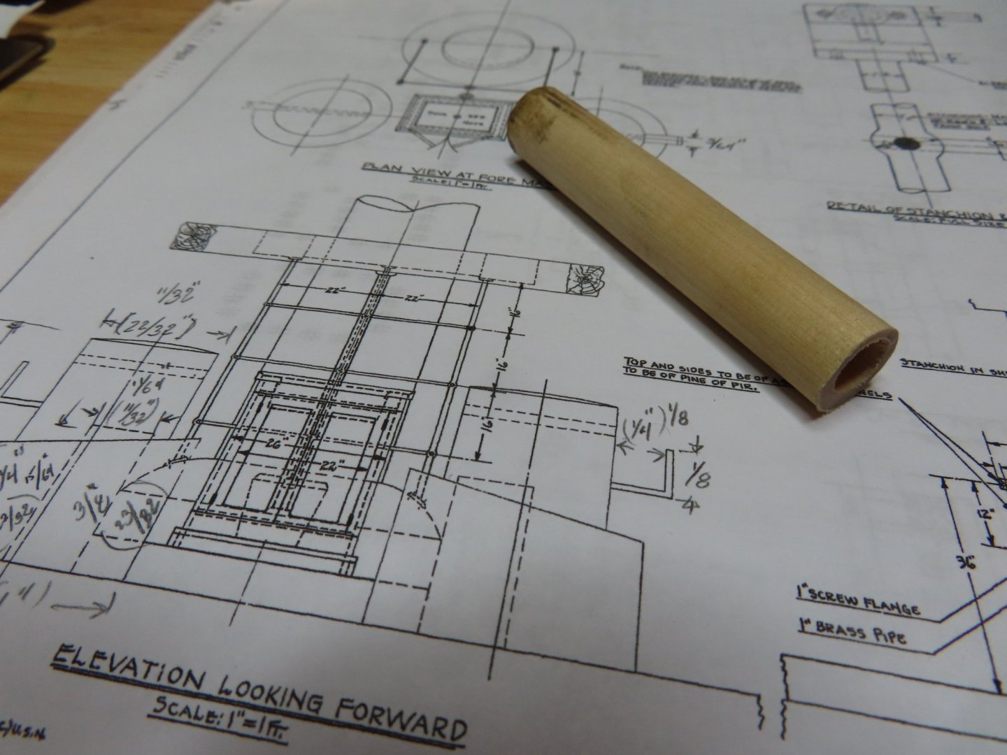
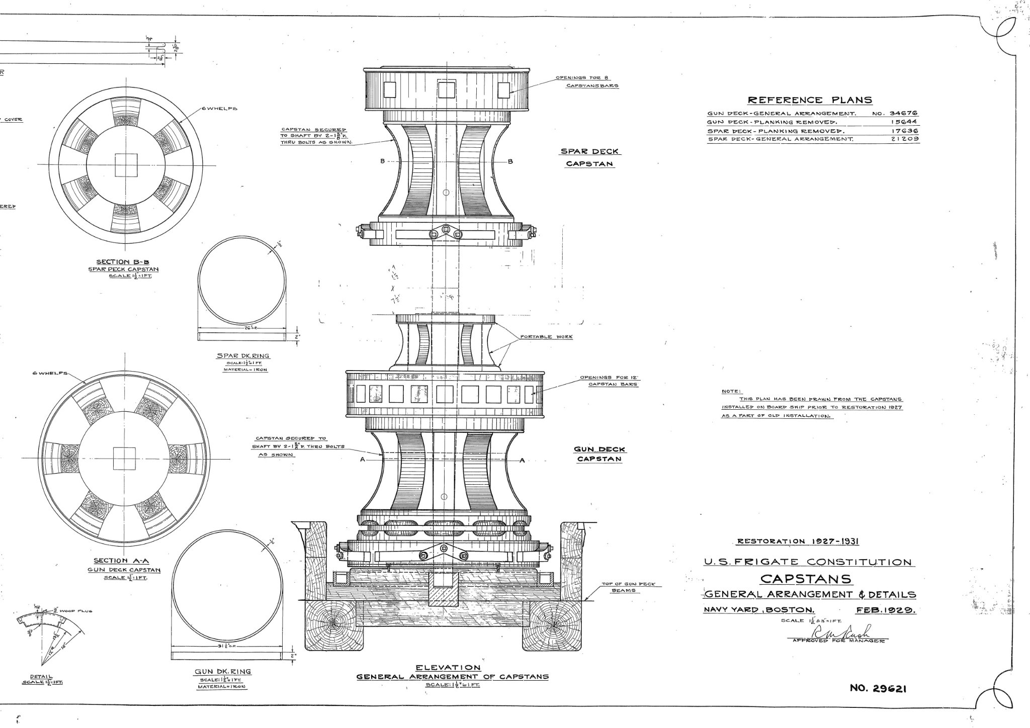
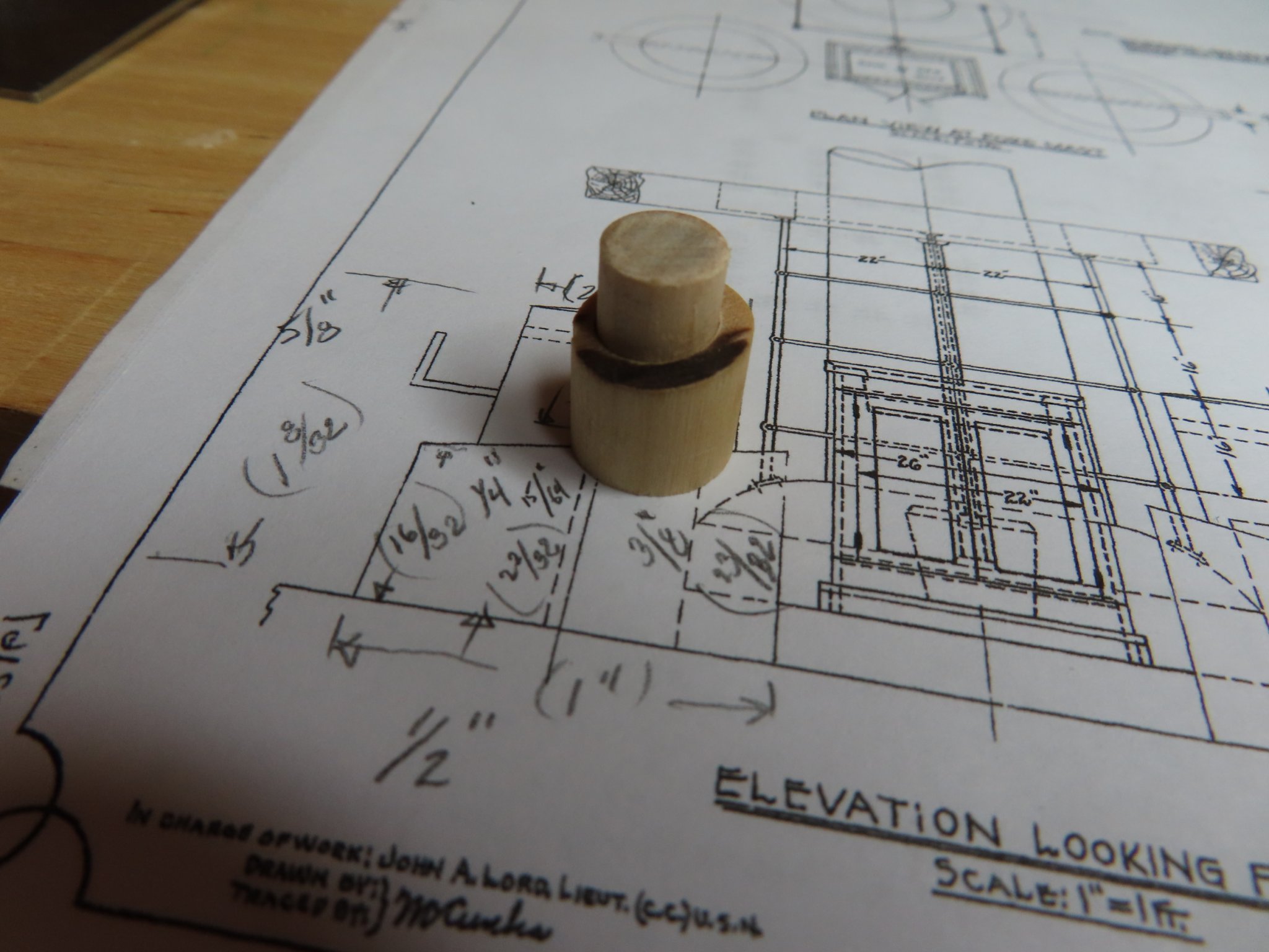
This capstan will be my first scratch capstan construct. I have the US Navy plan No. 29621 “Capstans” with a lot of the detail. It indicates only the major dimensions. If I had the full-size plan, then the scales on the plan would have been useful, but I don’t. Obviously, mine are printed on my home printer so the marked scales are useless. However, the dimensions for various lengths of items shown on the plan can be used to determine the 1:76.8 scale required.
1. Measure the longest indicated dimension (for accuracy) shown on the plan with a ruler.
e.g. 5 27/64” measured = 11’ 9 ½” indicated on plan
2. Calculate what 1” or 1/32” would represent on the drawing
1” calculated = 26.1” on plan
1/32” calculated = .816” (~13/16”) on plan
3. Measure a length from the plans with no indicated dimensions and multiple it by the appropriate conversion multiplier then divide by 76.8
e.g. measured 7/32” from the plan:
· 7 x .816 = 5.712
· 5.712/76.8 = 0.074” or about 5/64” (0.0781”) scale

-
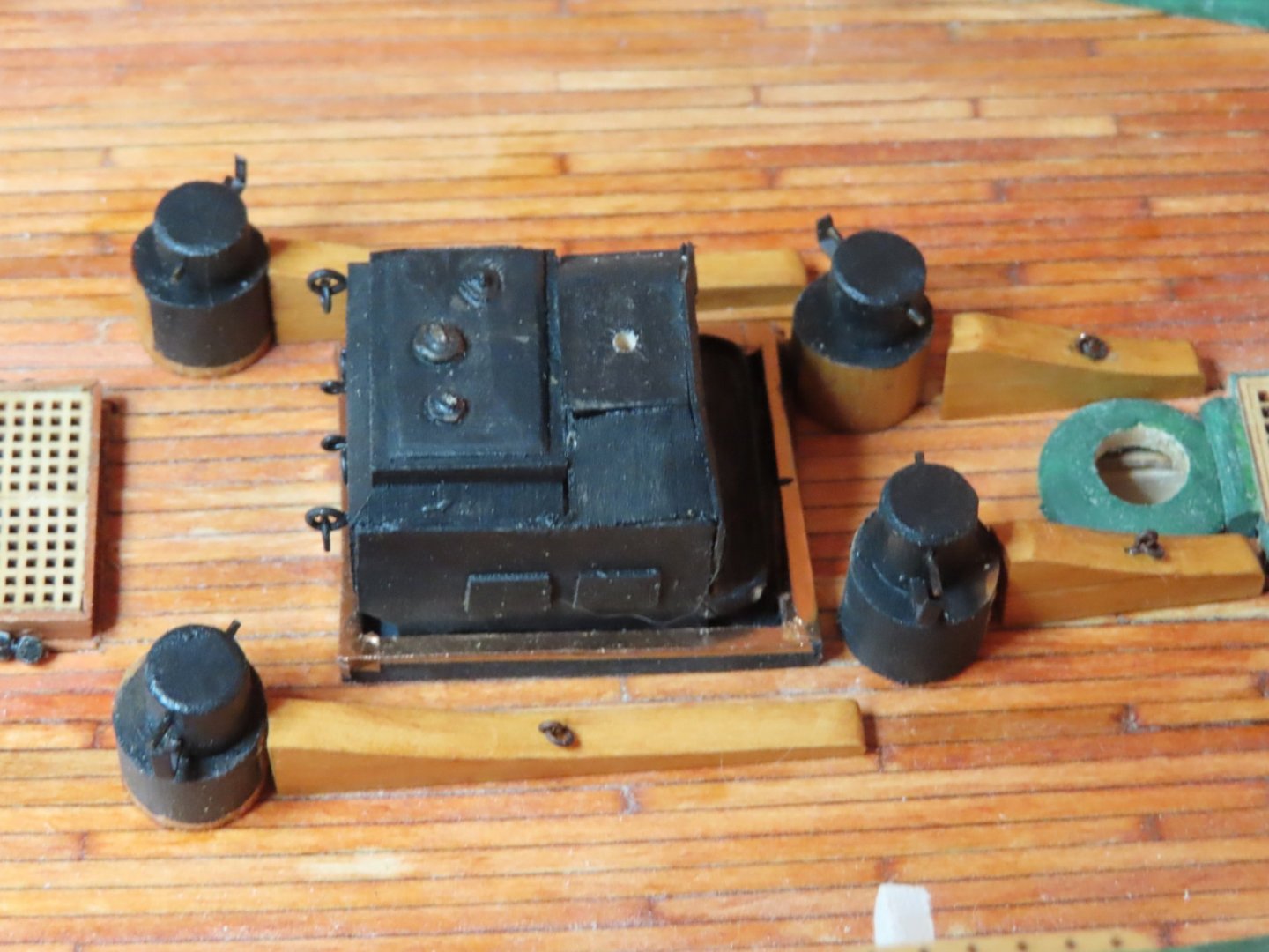
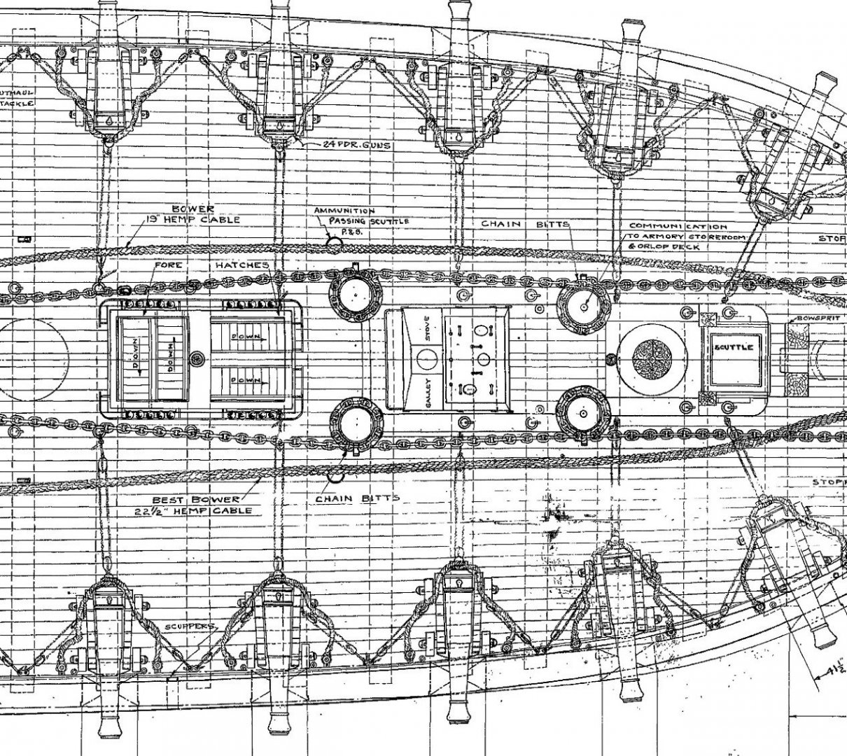
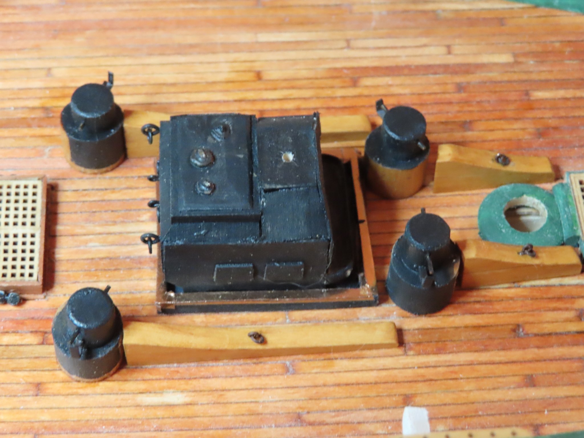
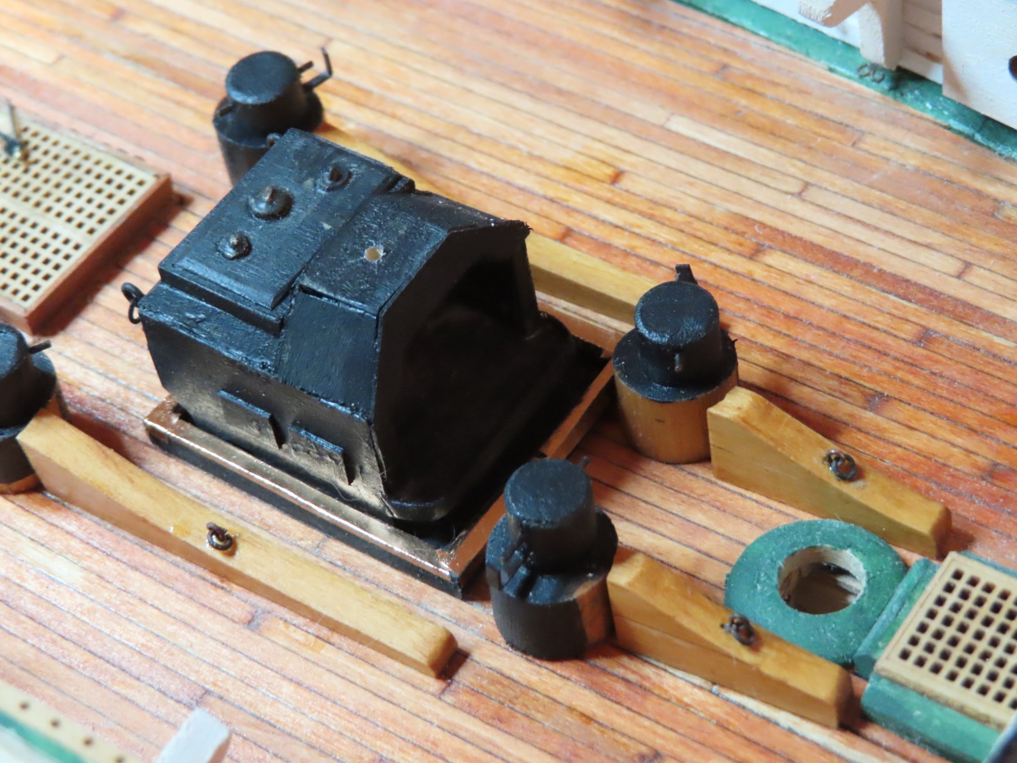
The completed chain bitts are just sitting on the model for the photos. They will be installed at a letter date to preclude any damage while I fabricate the other elements of the gun deck.

- usedtosail, KurtH and J11
-
3
-
The rails had three coats of wipe-on poly applied and then I added the eye bolts and rings. The bitts were a bit more complicated. I had to guesstimate where exactly metal cladding started and stopped because I couldn’t find anything on the Navy plans and none of my reference library photos were shot with the purpose of showing the cladding details as their subjects.
The navy plans do show the L-shaped bitt “guide” (?) so I was able fabricate those out of stock .016” copper plate which just happens to be almost the exact required thickness scale. The rods just above the guide were not in the Navy plans, so those were just eyeballed.

-
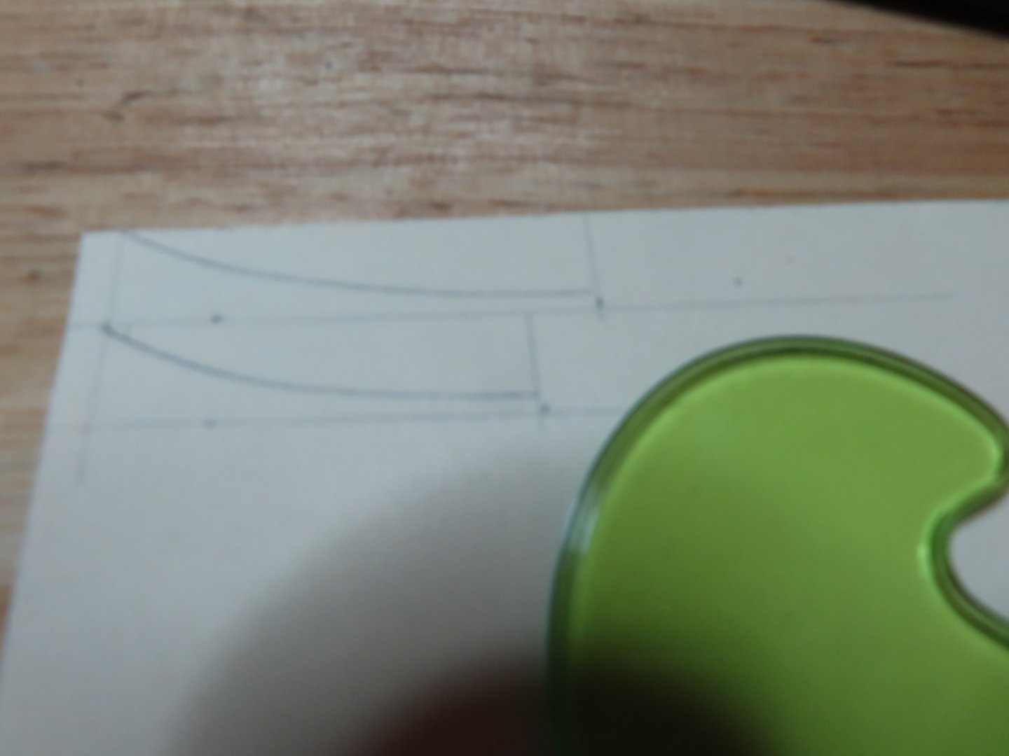
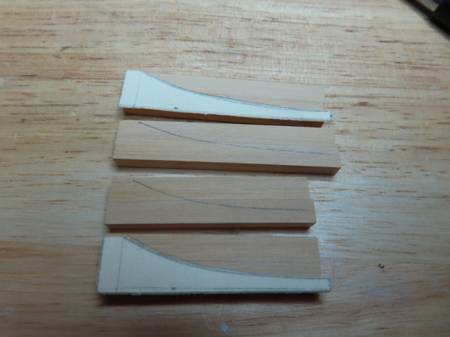
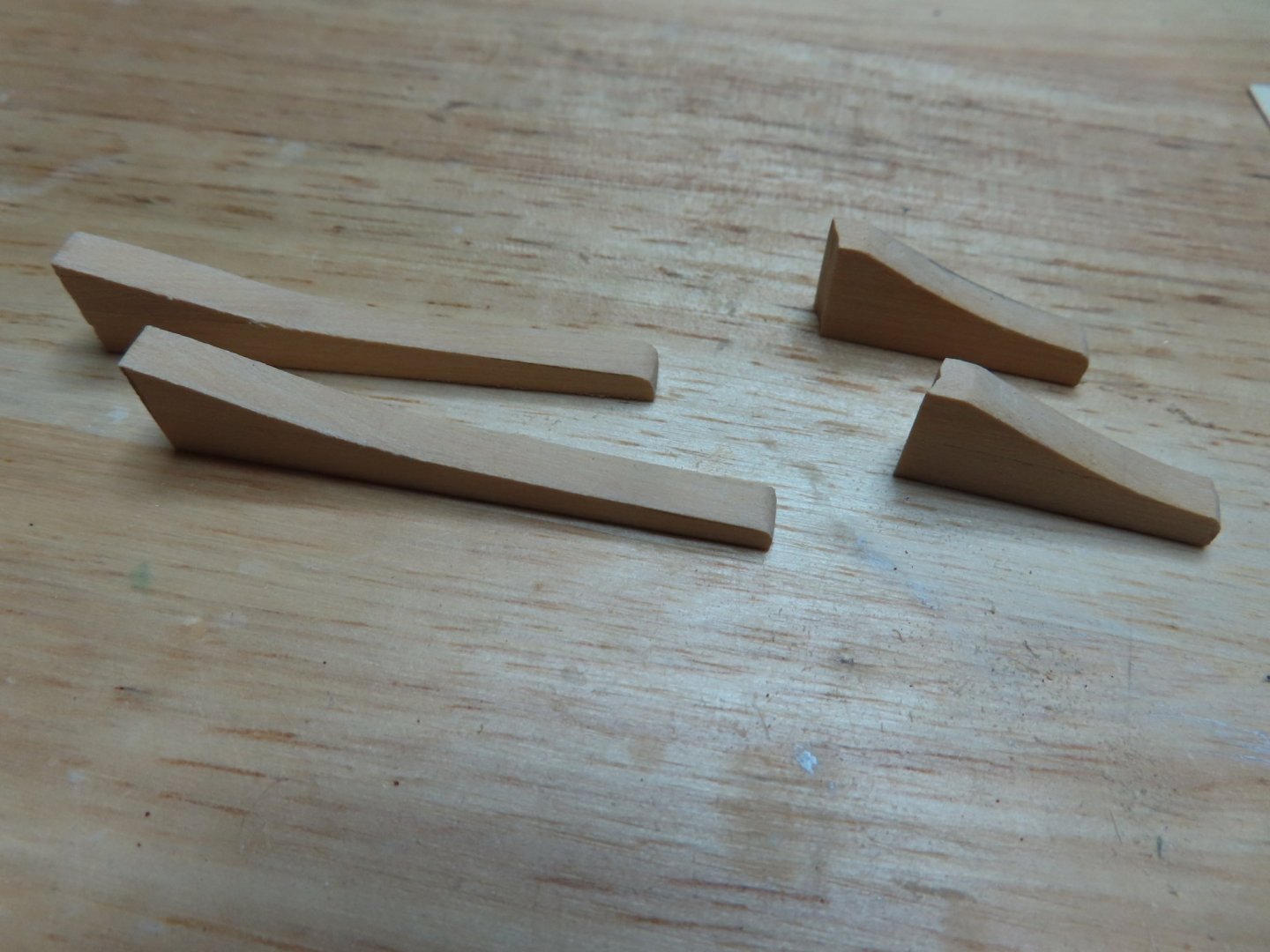
With the use of a French Curve, I guesstimated the curve shape and end points and drew them onto the rail blanks. Then with my scroll saw I cut them out. You will notice in the photos below, there seems to be a discrepancy with the before and after cut of the short rails. When the “before” photo was taken I had drawn the wrong curve length. This was caught before I made any cuts but didn’t retake the photo.
-
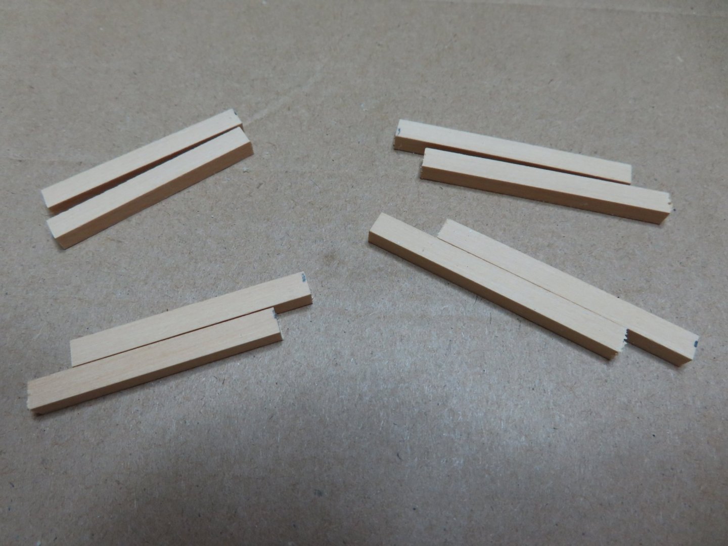
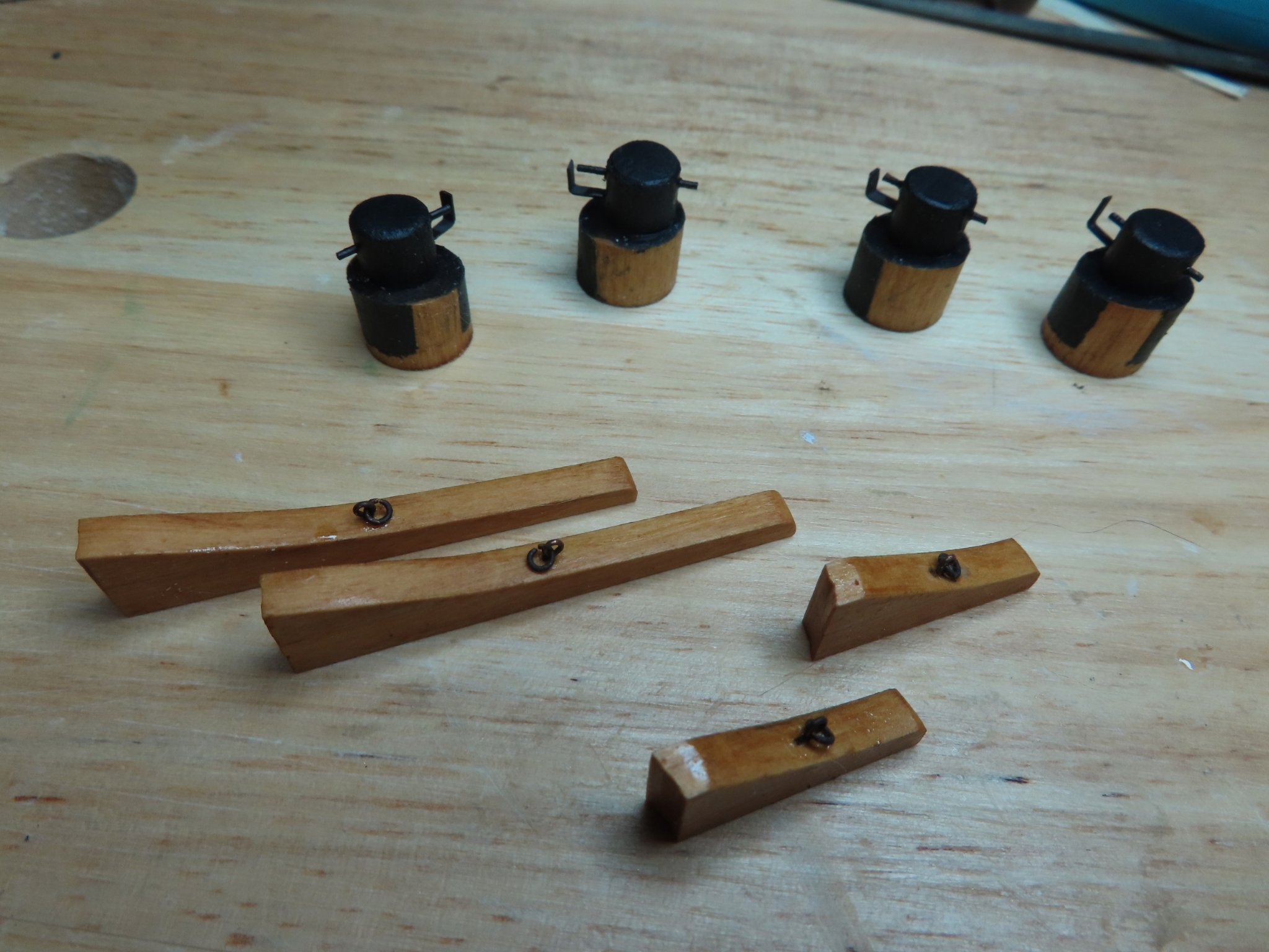
The next component is what I call the chain bitt rails, the swooping rail forward of each bitt. Scaling down from the Navy plans, I worked out the basic block dimensions I need to cut these rails from. The long pair was 3/8” H x 5/32” W x 1 7/8” L and the shorter pair was 7/8” L. Because the rail was bare wood, I chose to use boxwood, but as it turned out, I only had 3/16” x 5/32” stock. Thus, I glued two pieces together to get the required height.
-
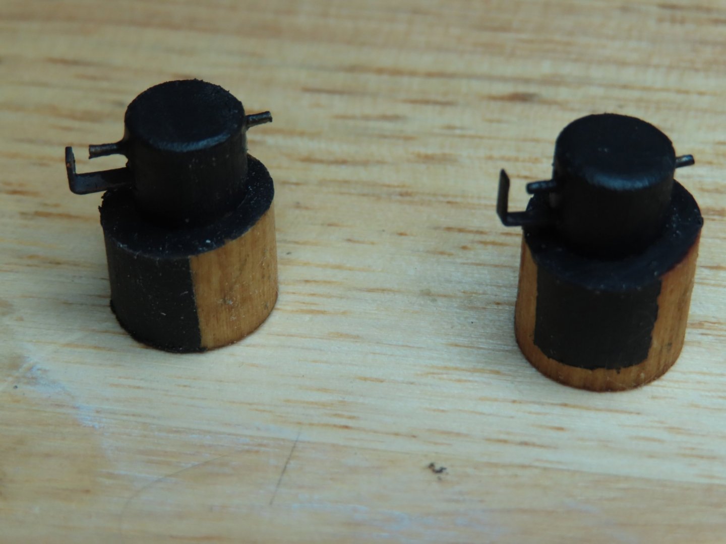
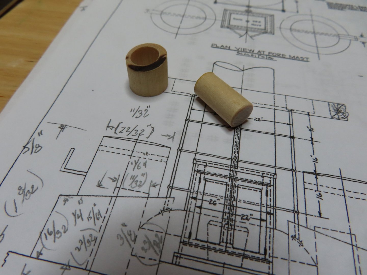
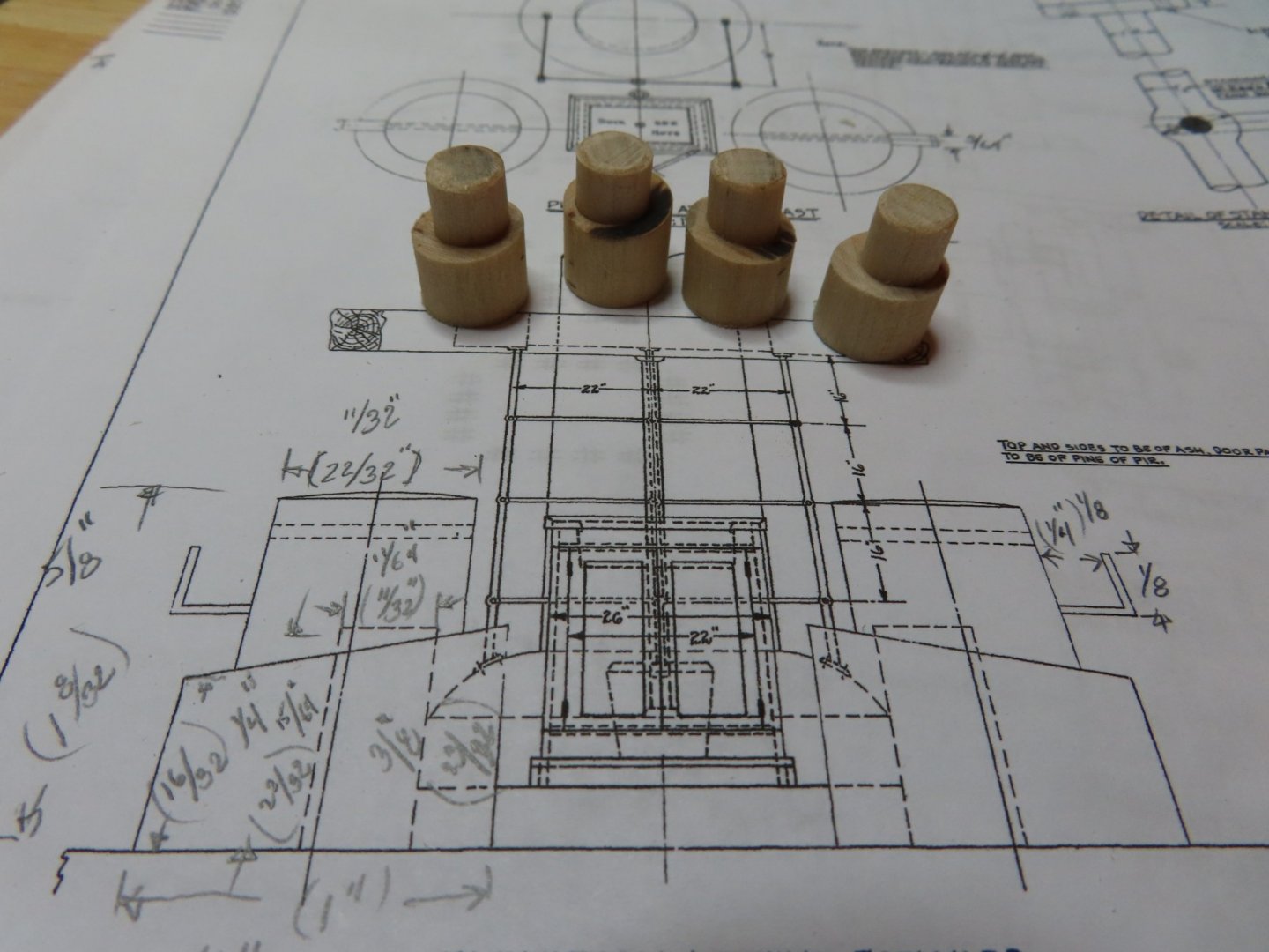
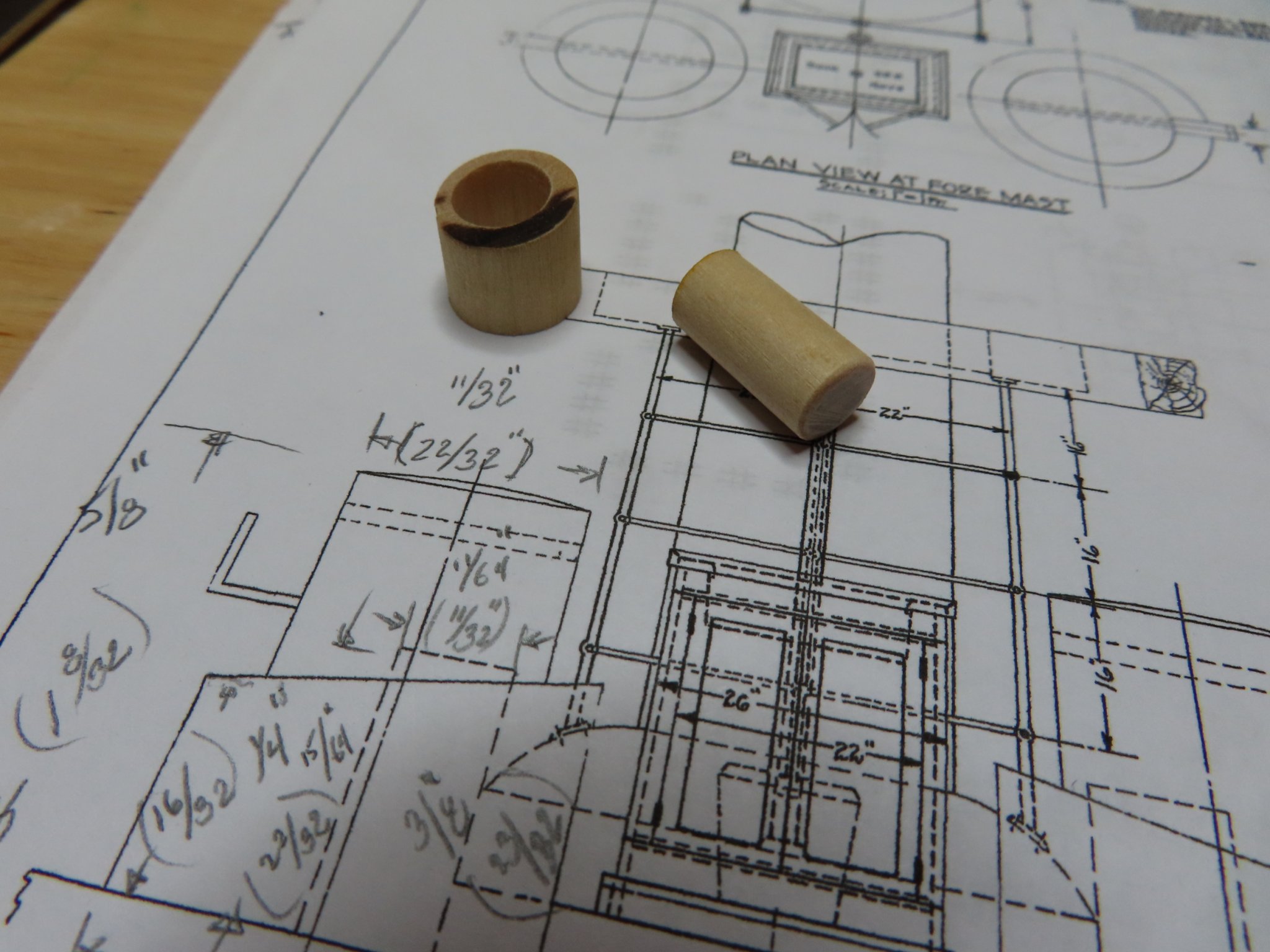
The lower portion of the bitt worked out to be ½” diameter while the upper portion came out to be approximately 3/8” diameter. What makes the construct a bit more complex is the top surface of the lower wider portion has a tilted surface, a difference in height of 1/8” scale between one side and the other. My solution to this fabrication puzzle was to first drill a hole 3/8” in diameter straight through the ½” dowel on a lathe enough for 4 bitts using progressively larger drills. Next, I sliced 4 pieces off making 4 tall wooden donuts. Then, using my disc sander, I tilted the sanding plate 9° and sanded one surface to create the bitt’s tilted surface. Then I sliced a 3/8” dowel into four 5/8” pieces. Each of the pieces were then inserted into the donuts and voila…I have the basis of chain bitts.

- J11, JeffT and usedtosail
-
3
-
-
Nikolay - If you are referring to the tapering at the bow and stern, I bent the planks first, then tapered them to fit. I knew how wide the planks had to be at each bulkhead and sanded them down by hand till they matched what I had calculated prior. The planks were tapered no more than half the original width. Because I had already formed the plank curve prior to tapering, I did not induce much stress to break the wood.
- Ryland Craze, JeffT and Nirvana
-
3
-
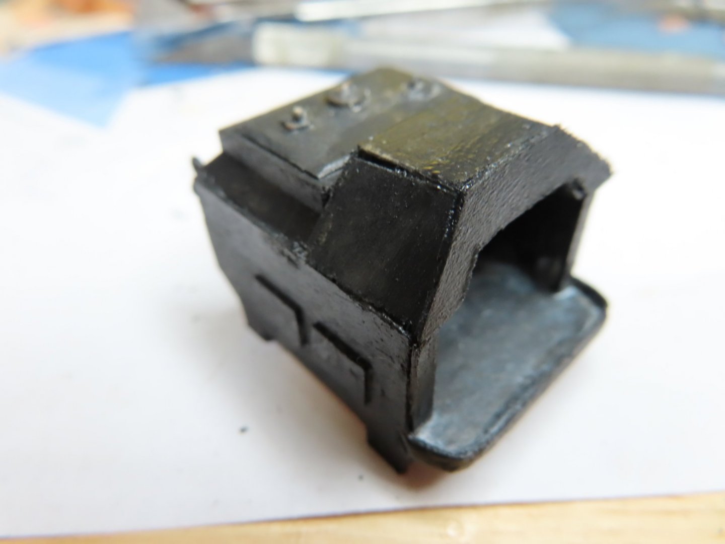
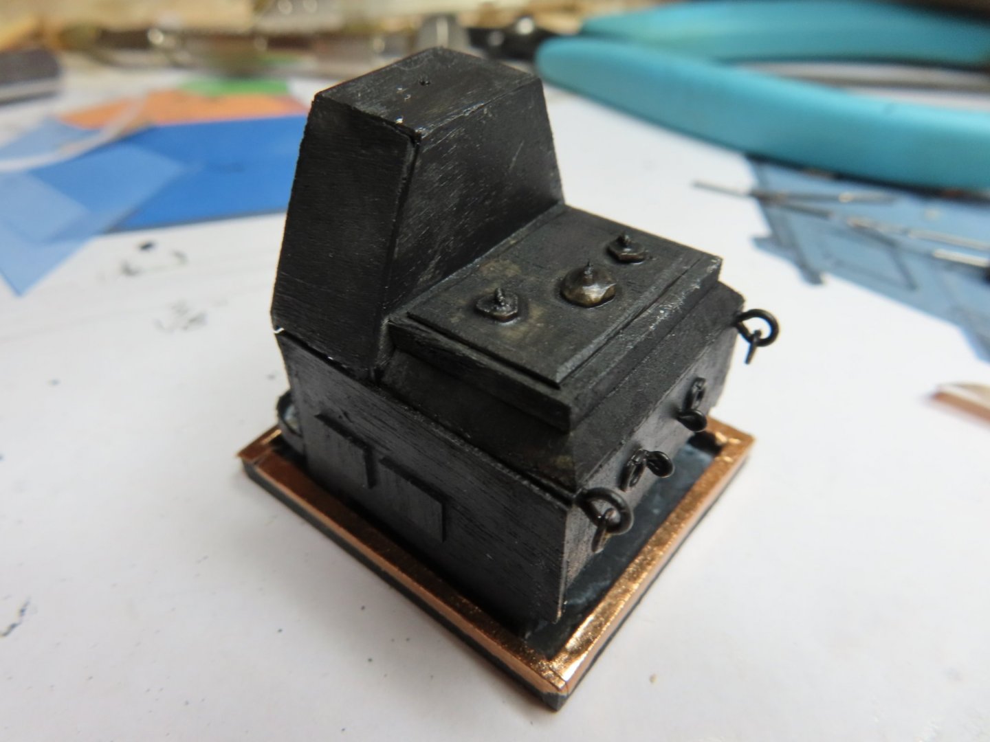
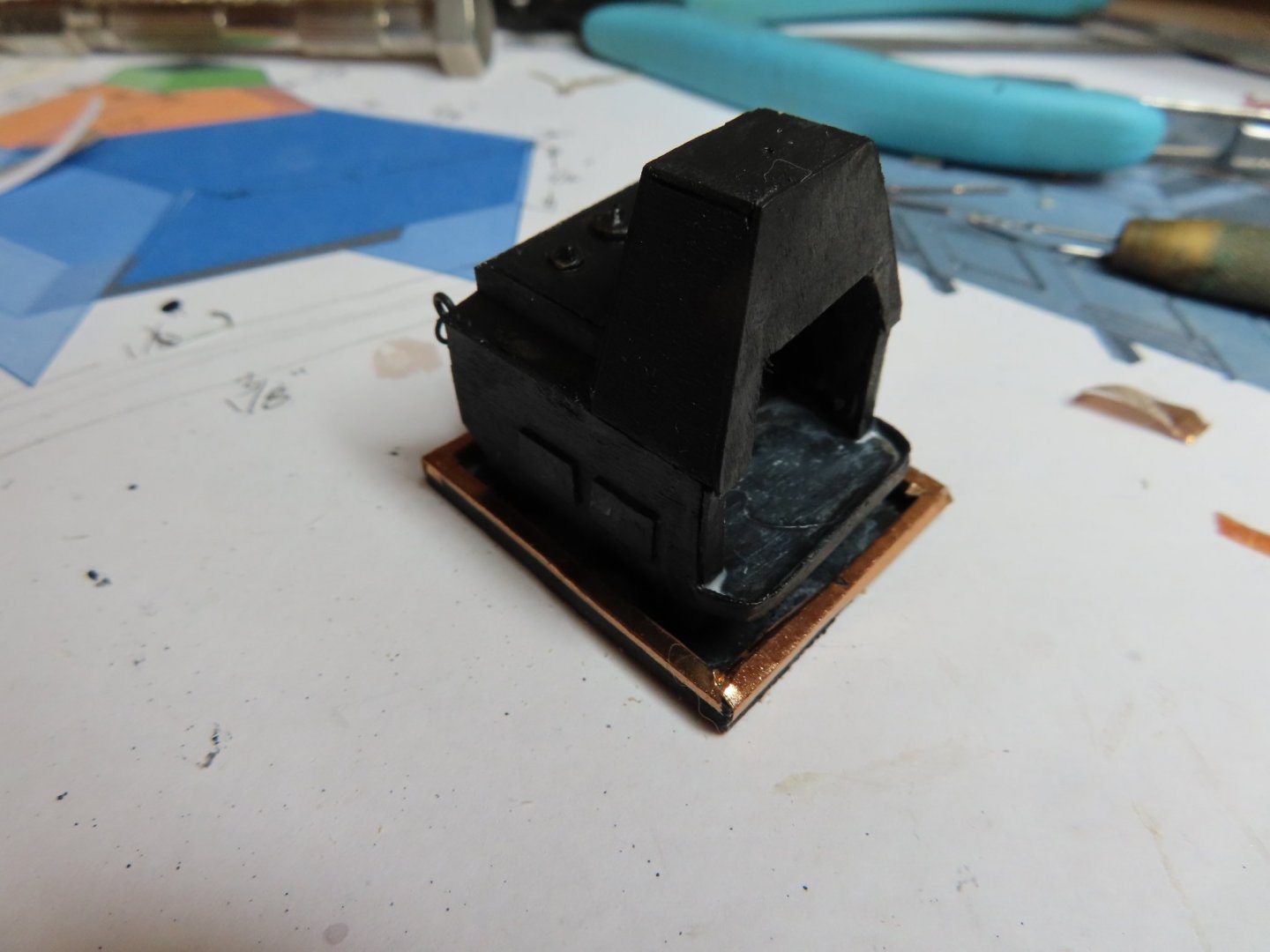
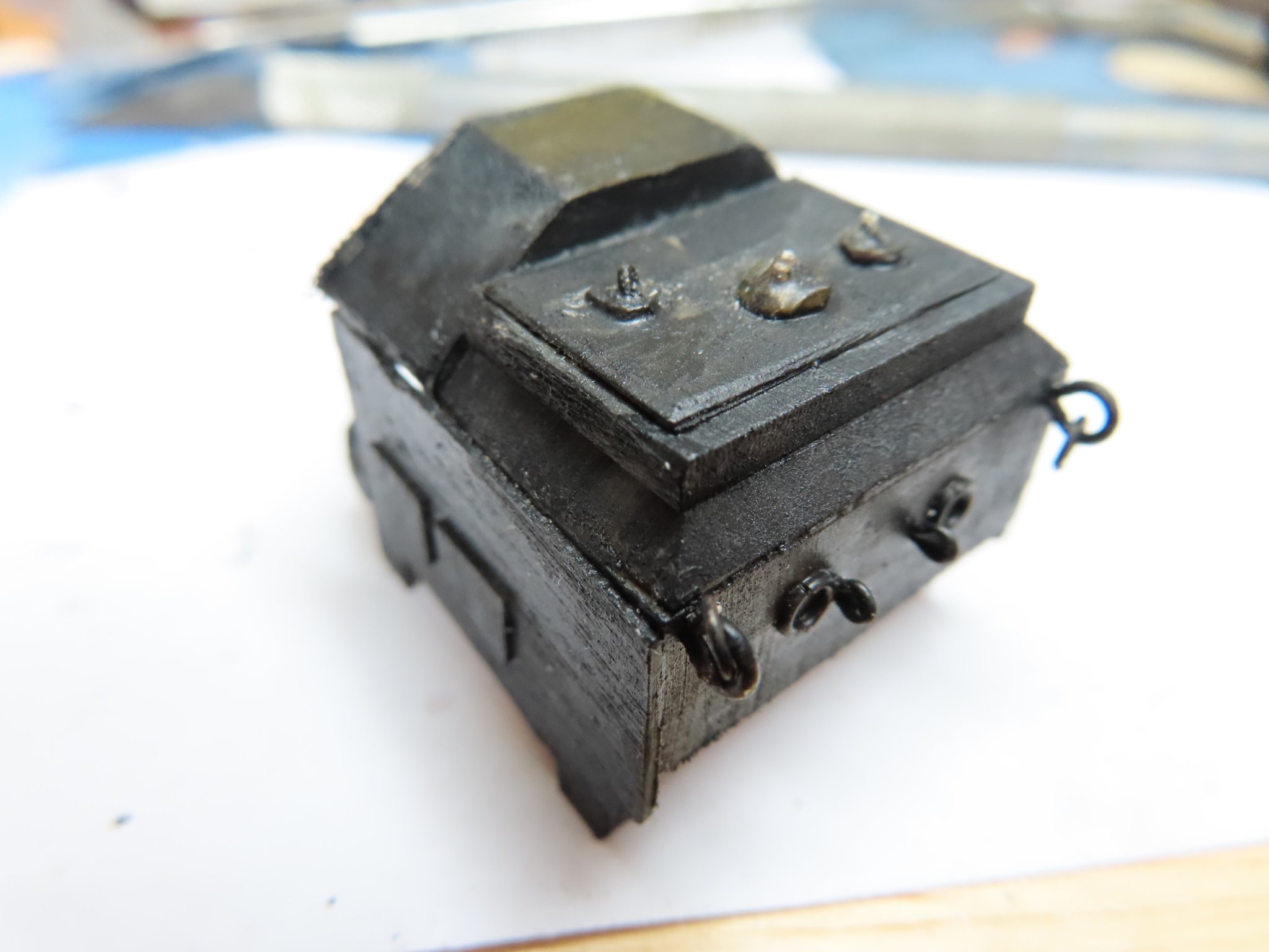
A new hood was constructed which definitely gives the stove a more compact look. Once more the hood was reassembled and glued into place. The new hood was painted and the whole stove was given another light coat to cover up some minor wood discoloration due to the additional work.


- usedtosail, KurtH, J11 and 1 other
-
4
-
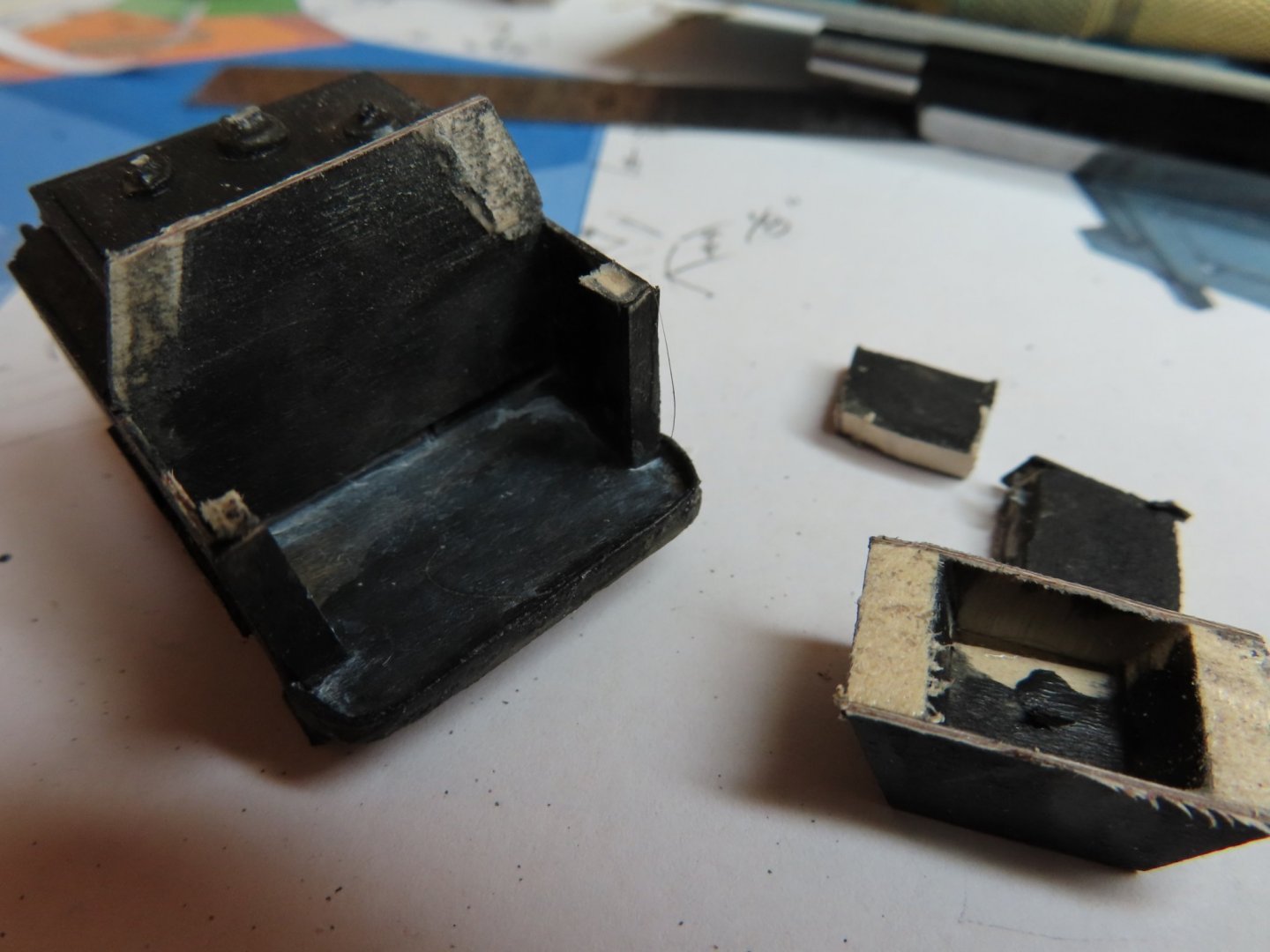
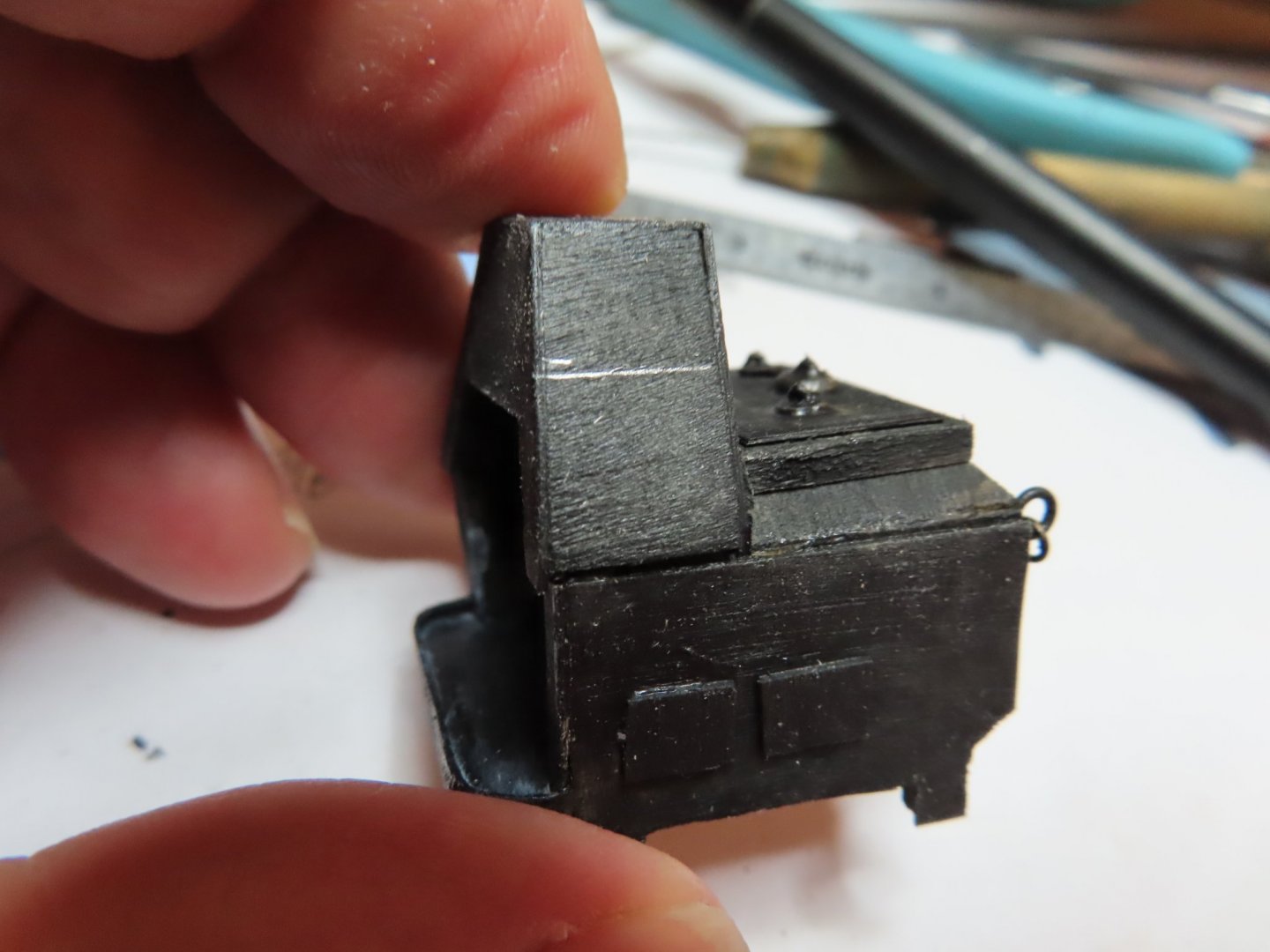
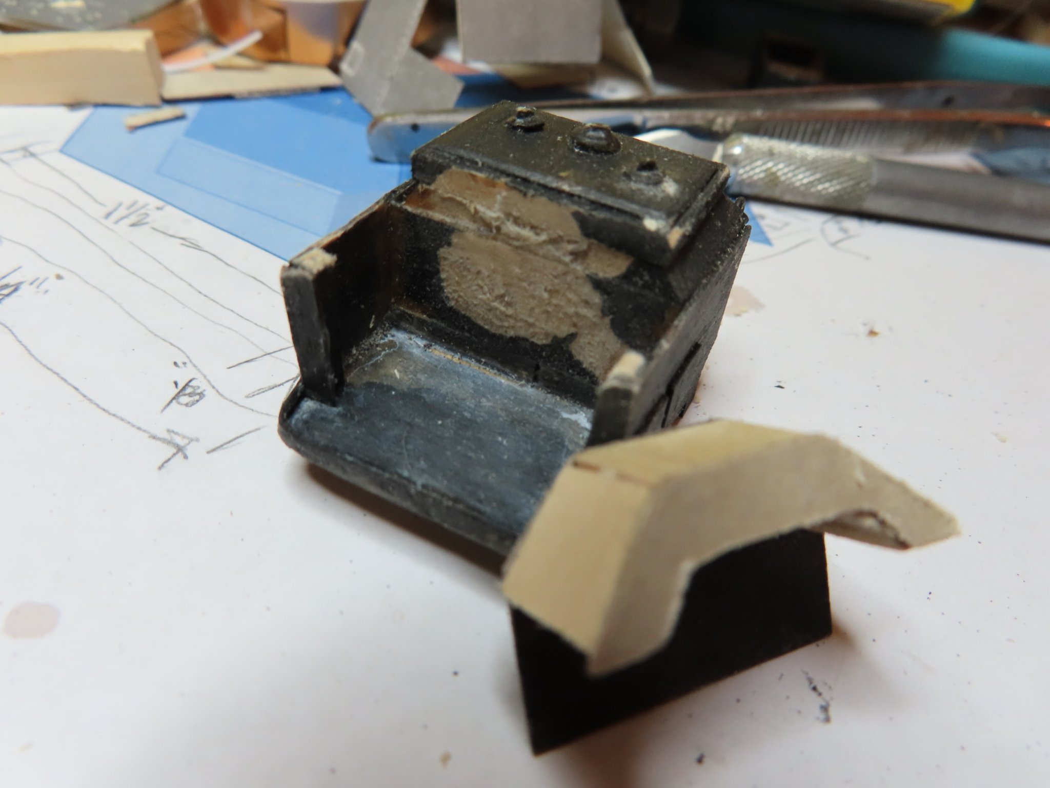
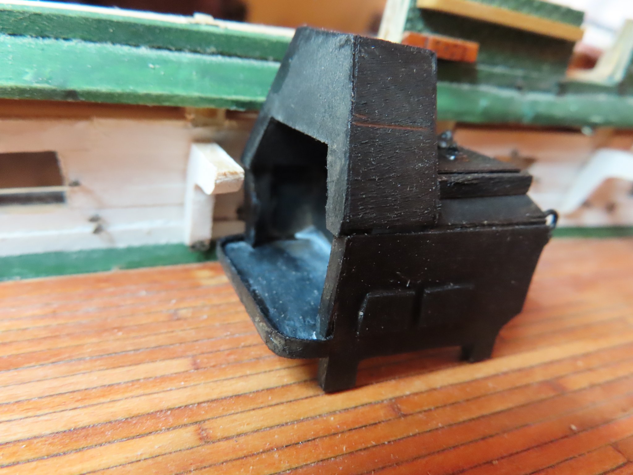
Well, I got lucky. I was able to slice off the excess portion of the stove hood as disassemble the back plate from the remaining portion of the stove. The stove was held together with PVC glue because it gave me a chance to make final adjustments before the glue set. I had used just enough glue to hold everything together but not super bonded that I could pry it apart.
- usedtosail and Ryland Craze
-
2
-
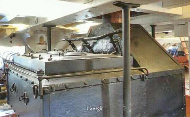
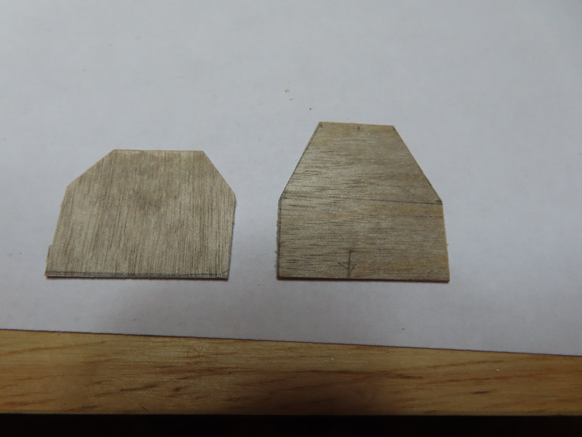
If you look at my original PowerPoint layout and the computer drawing, you will notice the stove hood is shaped like a trapezoid with a somewhat square box on top. The BlueJacket stove parts just had the trapezoid which made their stove’s height correct. When I converted my original design to match BlueJacket’s configuration, I incorporated the box’s height which I shouldn’t of. So, either I can somehow slice off the stove’s hood and rebuild a proper one or I must start over.

-
Well I knew it went too easy. All my stove dimensions match what is on the Navy plans except for one small detail: height. My stove is too tall. I drew a line on the stove’s hood where it should have stopped.

- Tigersteve, Nirvana, J11 and 1 other
-
4
-
JJT - The reason the kit does not provide a stove is that the kit was not designed to have a viewable gun deck. All the kit has is the stove's Charlie Noble (stack) protruding on the spar deck. I chose to add the gun deck which means everything on it has to be scratch built if it's going to be seen or partially viewable.
- Ryland Craze and JeffT
-
2
-
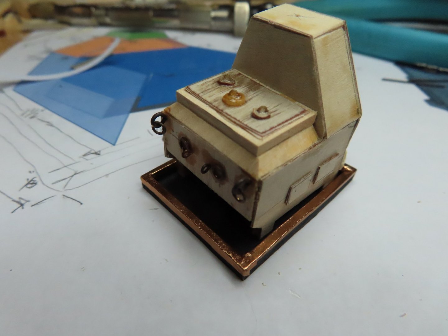
At this point I said to myself, “awe what the hell” and added a couple pieces of 1/64” plywood to each side of the stove to simulate side door panels and some eye bolts and rings. I also added a thin whitewash to the surface of the tray as well as to the surface of the tray inside the stove. This again is to reflect what I saw in the photos. Unless there is a strong light on the stove, most of these minimal details will be lost to the viewer in the completed model. Final mounting of the stove to the gun deck will after I have constructed and positioned the chain bitts and their associated accouterments
- JeffT, Ryland Craze, usedtosail and 4 others
-
7
-
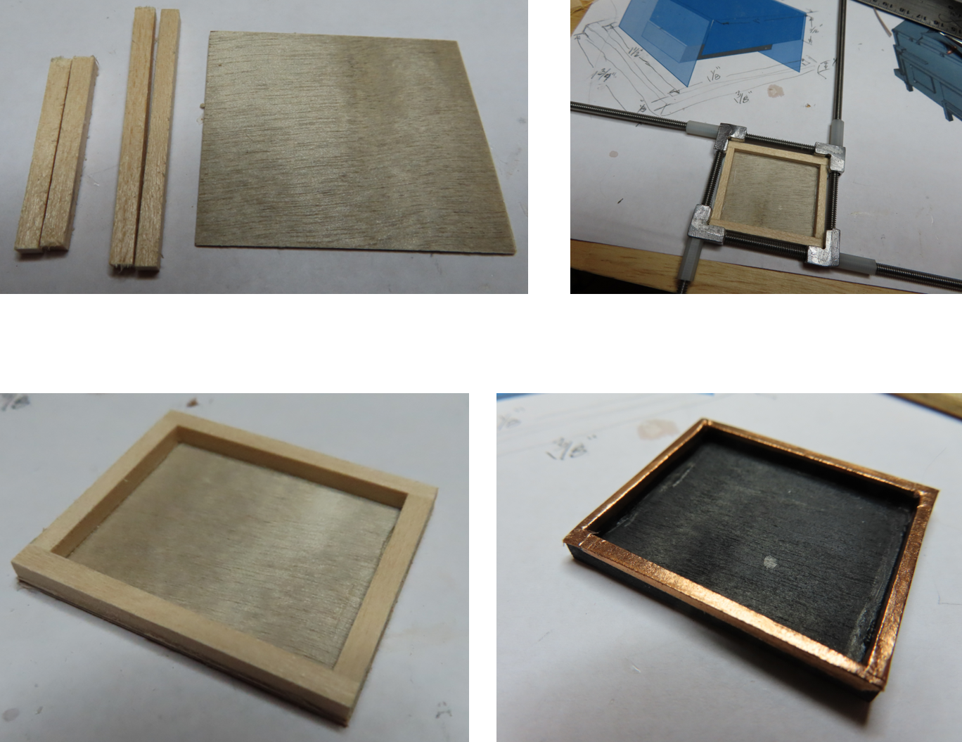
The stove tray dimensions were eyeballed and guesstimated from photos of the stove. The construction was simple enough. I used 1/64” plywood as the base and 1/8” x 1/8” basswood stock for the sides. I finally got to try out my clamp for making square frames for the first time after having purchased it so many years ago. All my other attempts to use it were failures because as small as it is, it was too big for most of my constructs I was attempting.
I got a nice result but trimmed off 1/32” from all four sides because the walls just looked too wide to my eyes. Based on the photos, I first painted the tray black, then used copper tape I got at a crafts store, to plate to top of the tray walls and partially down the sides. This copper tape is much thinner than the copper tape supplied by the kit for the hull plating.
-
What will added is the tray in which the stove sits. Surprisingly, the US Navy arrangement drawings do not show on their plans. At least I haven’t been able to find any.
- Ryland Craze, Papa, JeffT and 1 other
-
4
-
I might add some other details such as eye bolts and rings. However, considering that the whole stove is going to be painted black and place in a dark area below the spar deck, the effort to add more handles, a rod railing on the stove top, rivets which just can’t be seen, among other doodads is not worth the effort.
-
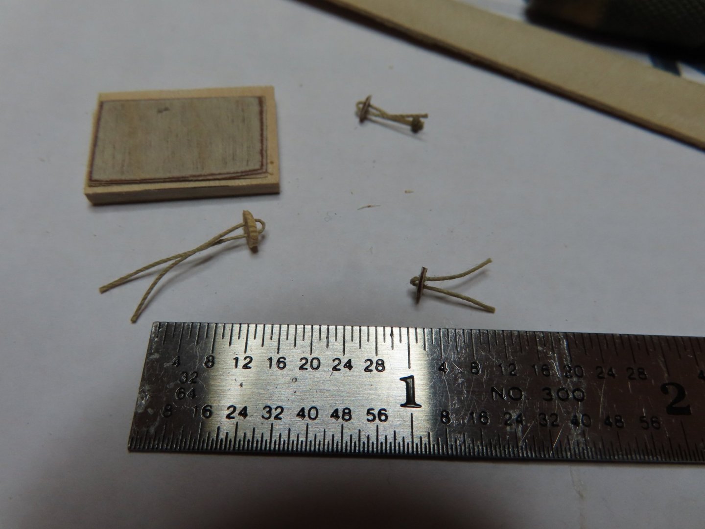
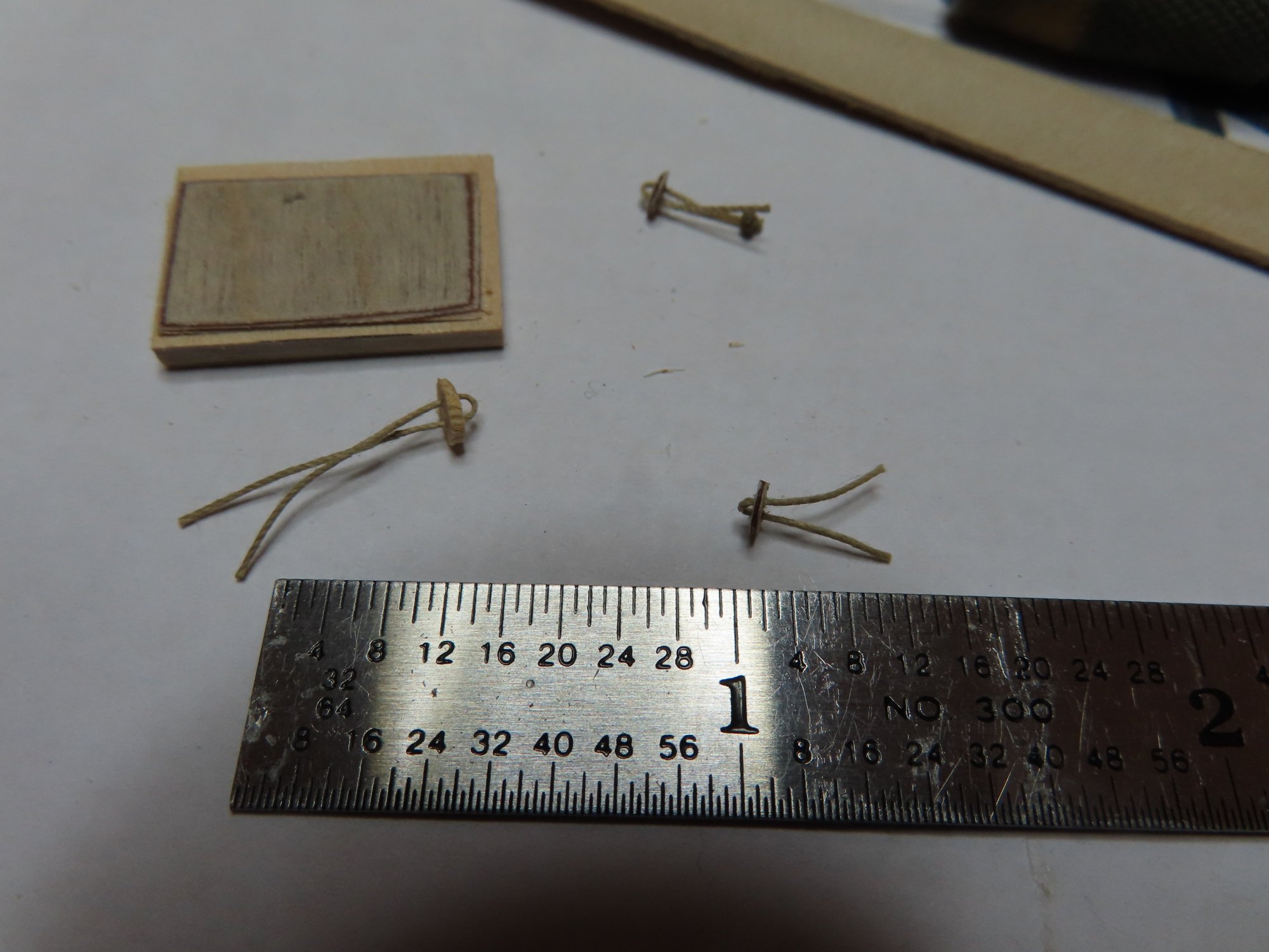
Once the plates were formed, I had to think a bit as to how to make their handles. I elected to use thread. It’s strong and easily handled. With a No. 80 drill, two holes were carefully drilled into the plates and then threaded to form a loop. CA glue was applied on the underside which was drawn up through the hoes. The thread became solid when the glue set. The excess thread below was cut off and the bottom surface was sanded smooth. Finally, the stove top was glued into place.
- usedtosail and Ryland Craze
-
2
-
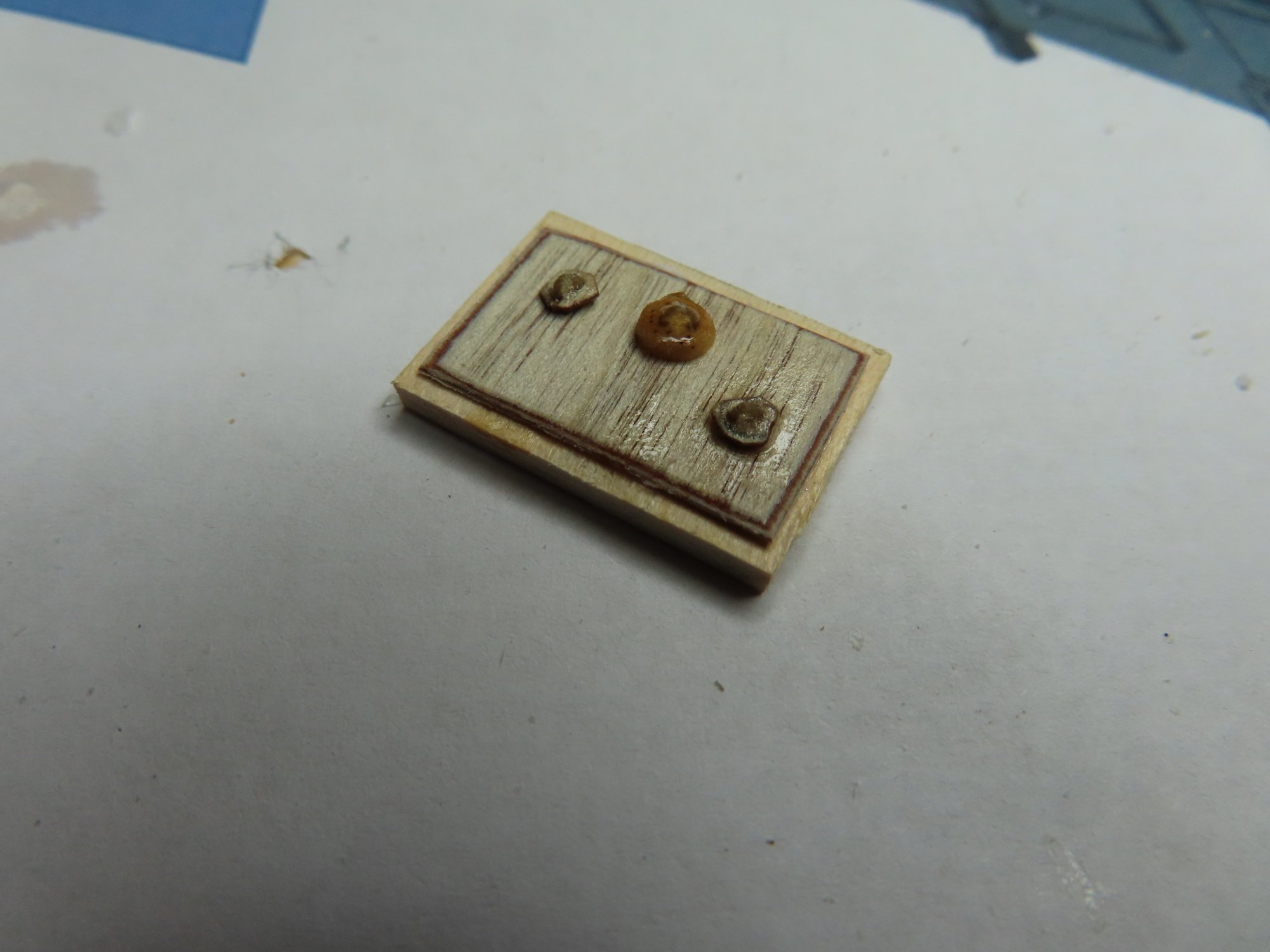
The last section to be completed was the forward-facing stove top. This was made from a piece of 1/64” plywood with beveled edges sitting on top of a piece of 1/32” plywood. Shown on the Navy plans and seen in the photographs, there are three oval and circular plates with handles. These things are exceedingly small and difficult to hold and shape. I tried slicing a thin dowel, but tiny pieces kept breaking off because the grain of the wood was perpendicular to the sliced flat surface. After numerous attempts only one survived. I ended up using 1/64” plywood filed to shape. The results were a bit ragged.


USS Constitution by JSGerson - Model Shipways Kit No. MS2040
in - Kit build logs for subjects built from 1751 - 1800
Posted
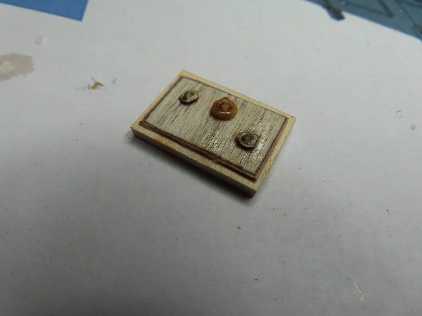
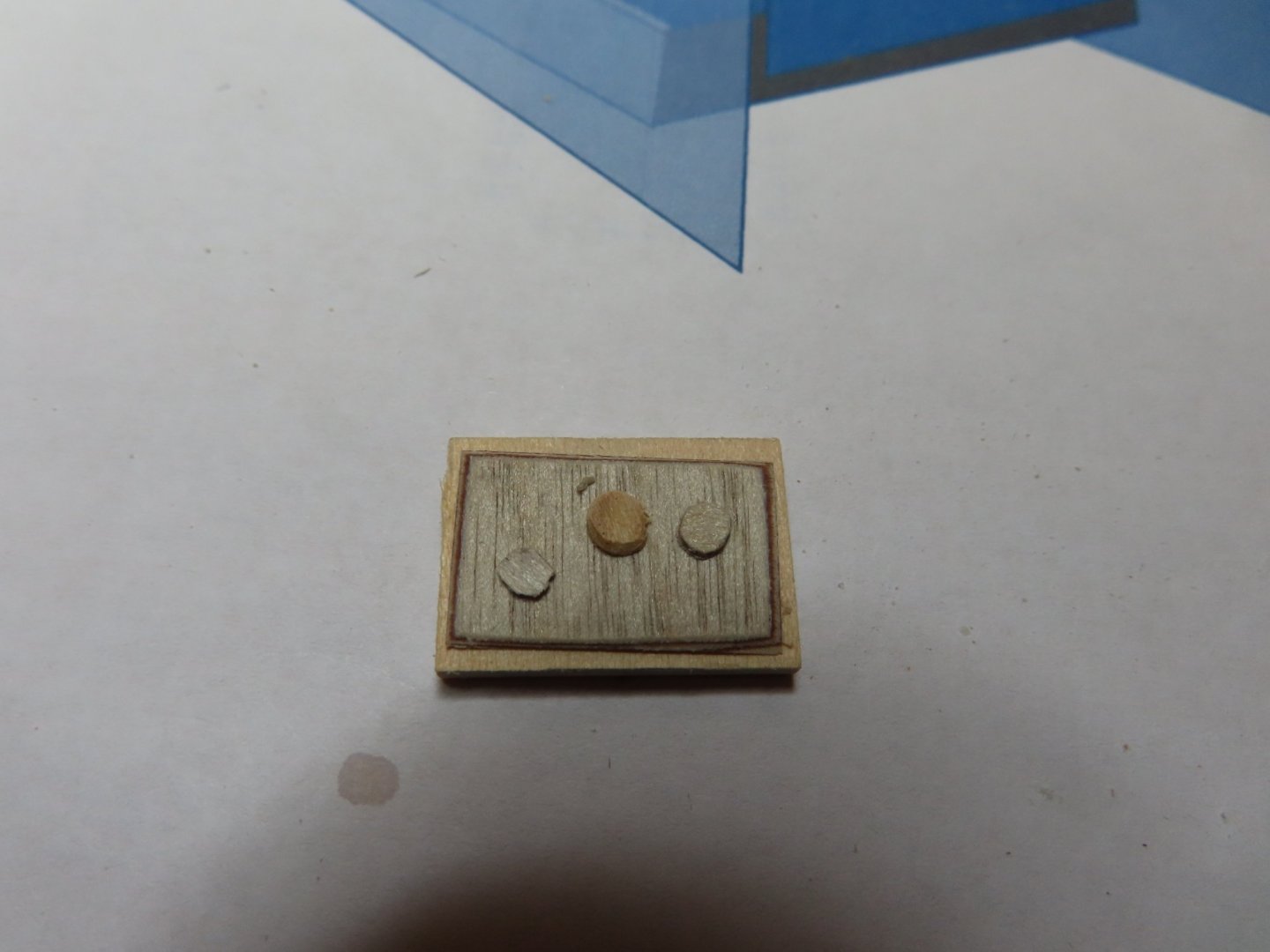
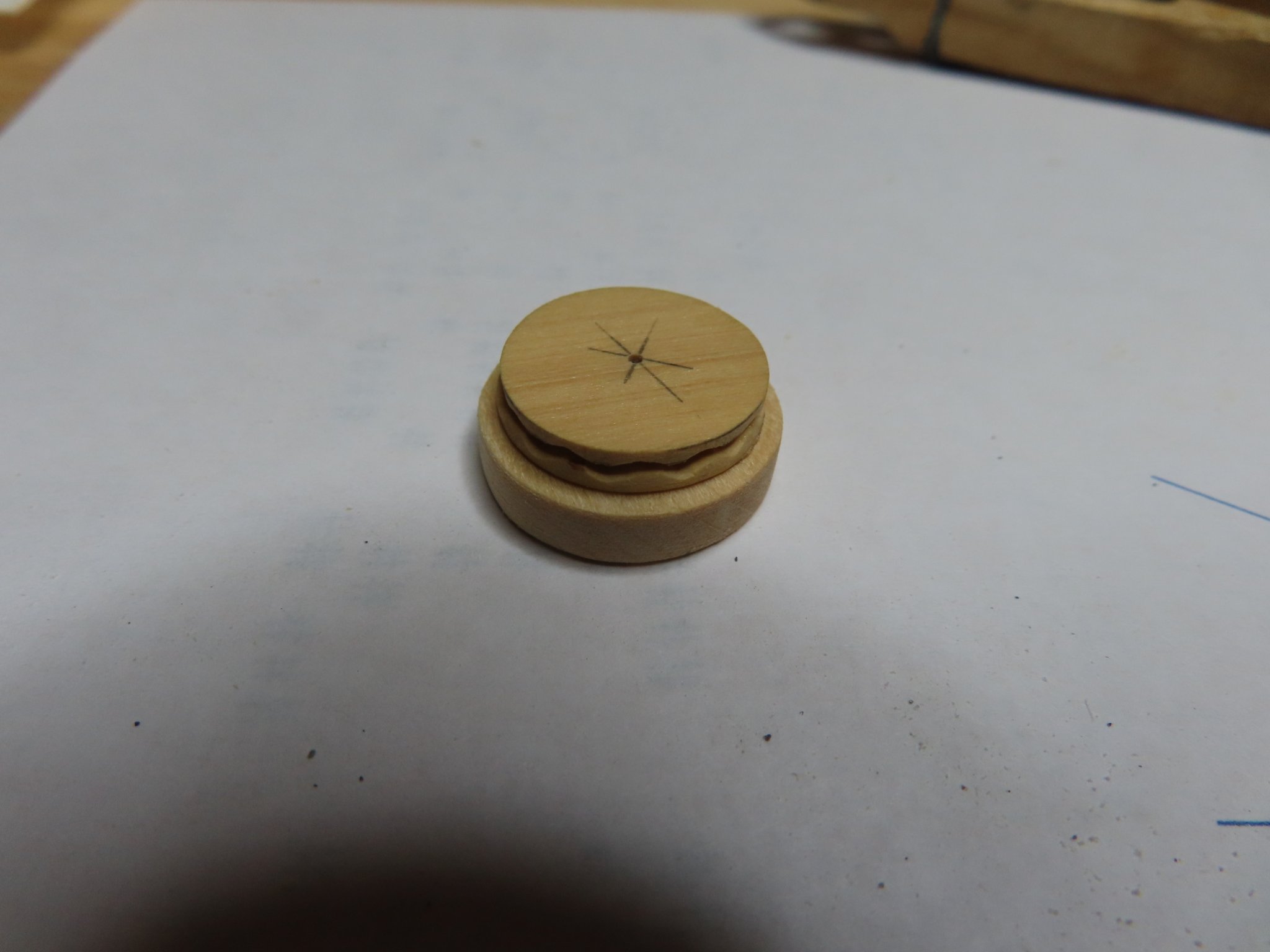
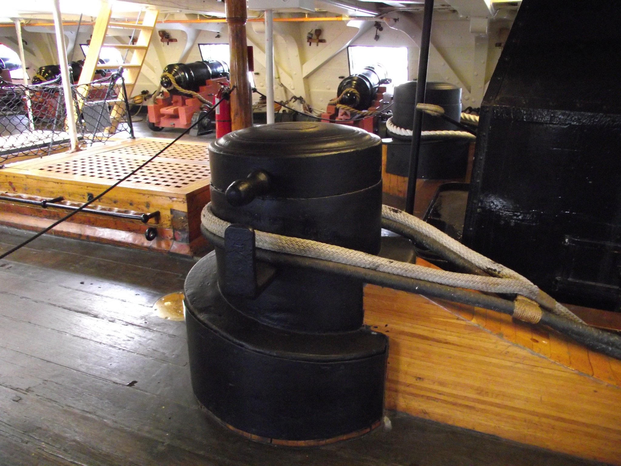
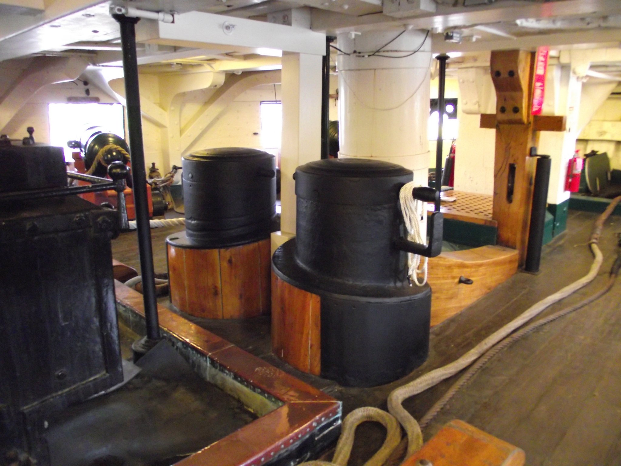
This time I constructed a third, 1/16”, thick ring. Guidelines were laid out for the purpose of making twelve 1/16” notches. Why twelve you ask? If you look closely at the actual capstan, every other square cutout in the brass plating is not hollow, but solid wood. Why it was constructed this way, I don’t know, but there it is. My brass “plating” is brass tape I got at Hobby Lobby, a crafts store. And attempting to cut out 1/16” x 1/16” openings cleanly directly on the tape is almost impossible for me at least. It is much easier to cut out the squares if there is an opening behind the tape that a sharp tool can easily pass into using the opening as a guide for the blade.
The Byrnes saw was perfect for the job for cutting the notches. The cuts were made by eyeball following the guidelines. This notched ring became the “meat” in my sandwich.