


JSGerson
-
Posts
2,168 -
Joined
-
Last visited
Content Type
Profiles
Forums
Gallery
Events
Posts posted by JSGerson
-
-
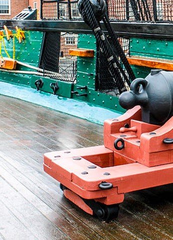
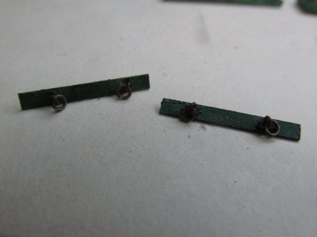
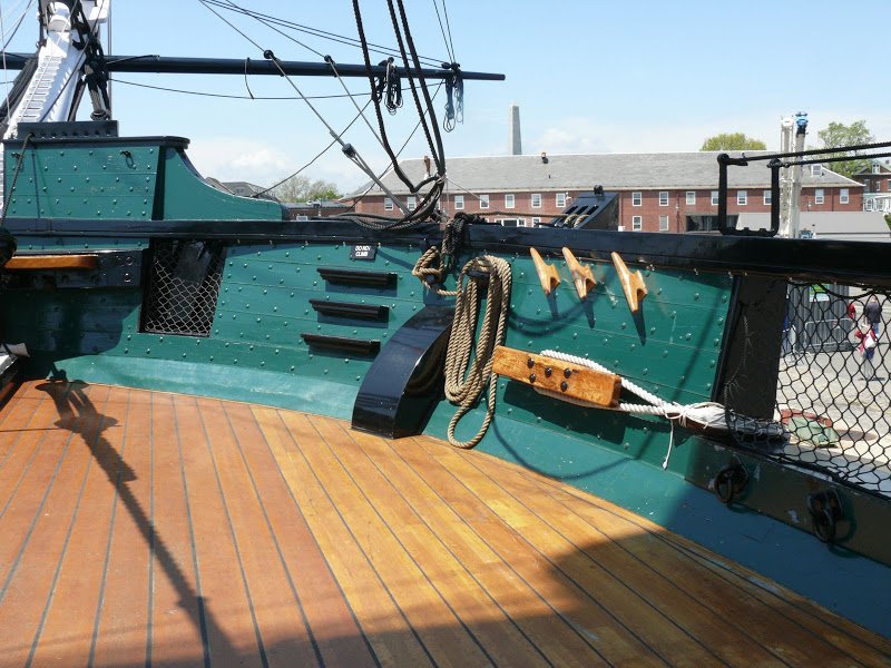
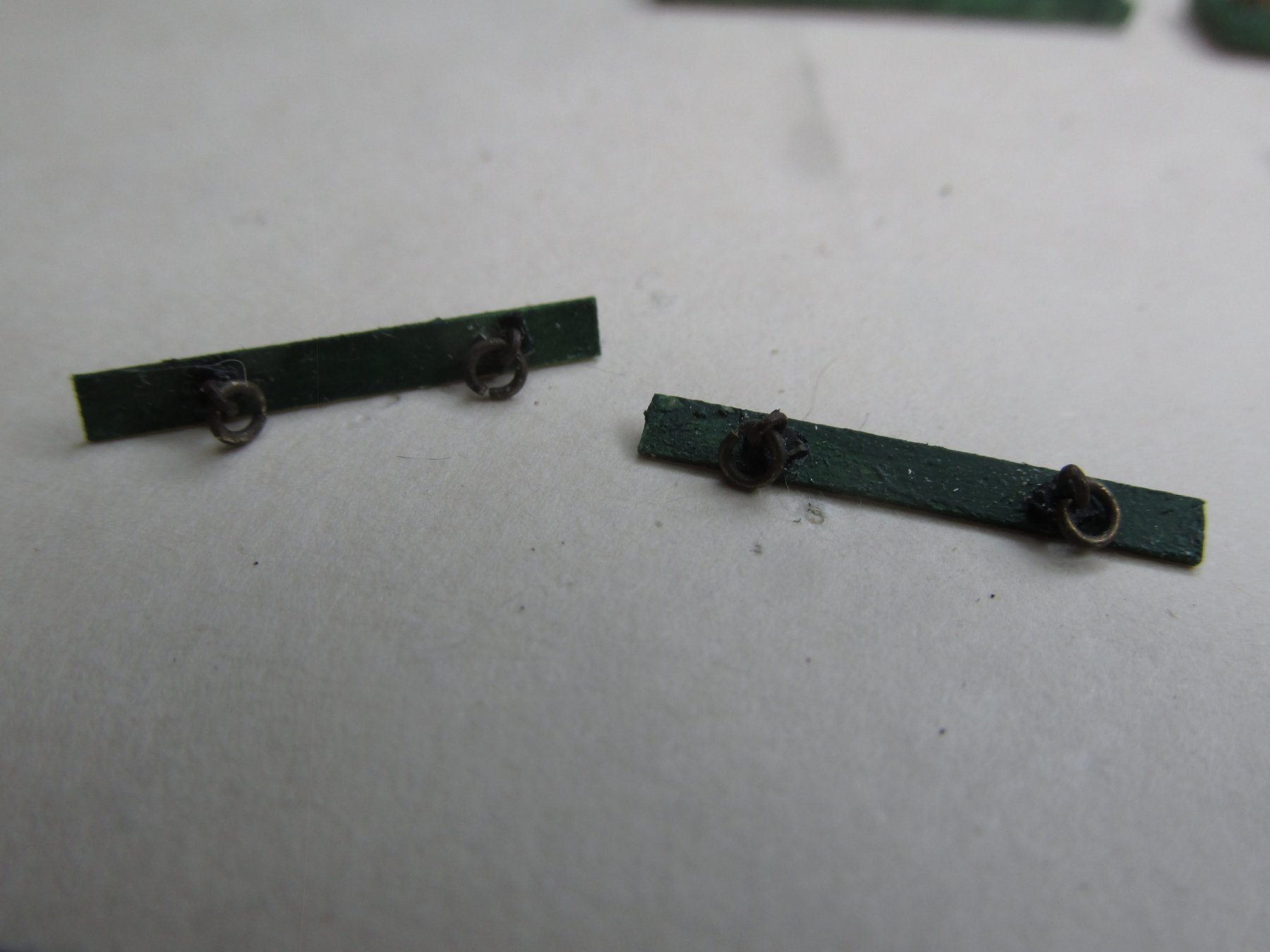
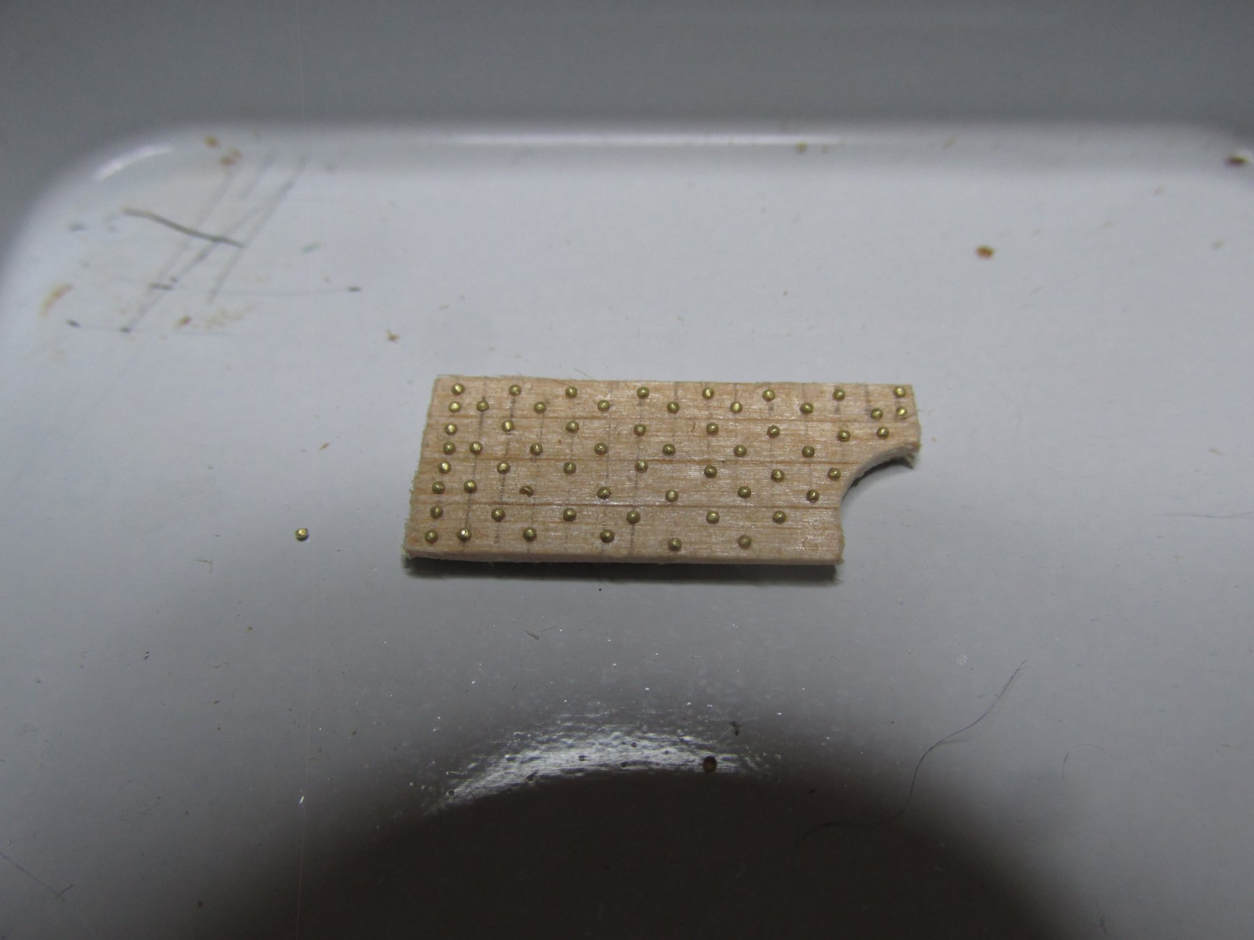
Additional to the hardware and pin rails on the bulwarks, the opening for the bow anchors had a couple of eyebolts and rings fastened underneath opening. The kit plans show those bolts but not the board they are fastened to nor the fact that the eyebolts have a base plate, and that they are at opposing 45-degree angles as well. My attempt at duplicating them is shown below. Compare mine against the actual ship. Sorry for the poor image, but that was the best my camera would do.
- GrandpaPhil, J11 and Ryland Craze
-
 3
3
-
Just as a matter of note, when I purchased the MS model kit and the associated practicum by Bob Hunt, some years past, Jeff Hayes’ HobbyMills was Bob’s wood supplier of choice but Bill has since retired and closed shop. He had supplied the supplemental wood required or suggested by Bob’s many practicums. In this case, Bob Hunt did not kit-bash the Constitution, but he did modify it a bit by substituting boxwood for certain basswood and laser cut constructs, which I am trying to follow. Bob felt the laser cut parts were too fragile.
At that time, Jeff Hayes offered a wood supplement package for those substitutions, which I purchased. That is where I’m getting my pre-sized boxwood substitutions from. Anything, I initiated, like the gun deck and all its associated accoutrements, the supplemental wood package did not cover. Whether some other wood supplier is selling those wood supplement packages today, you will have to check with Bob Hunt, I don’t know.
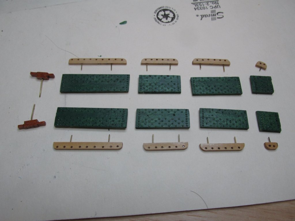
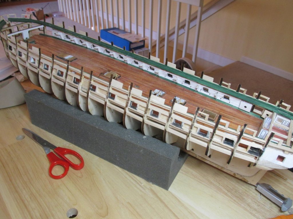
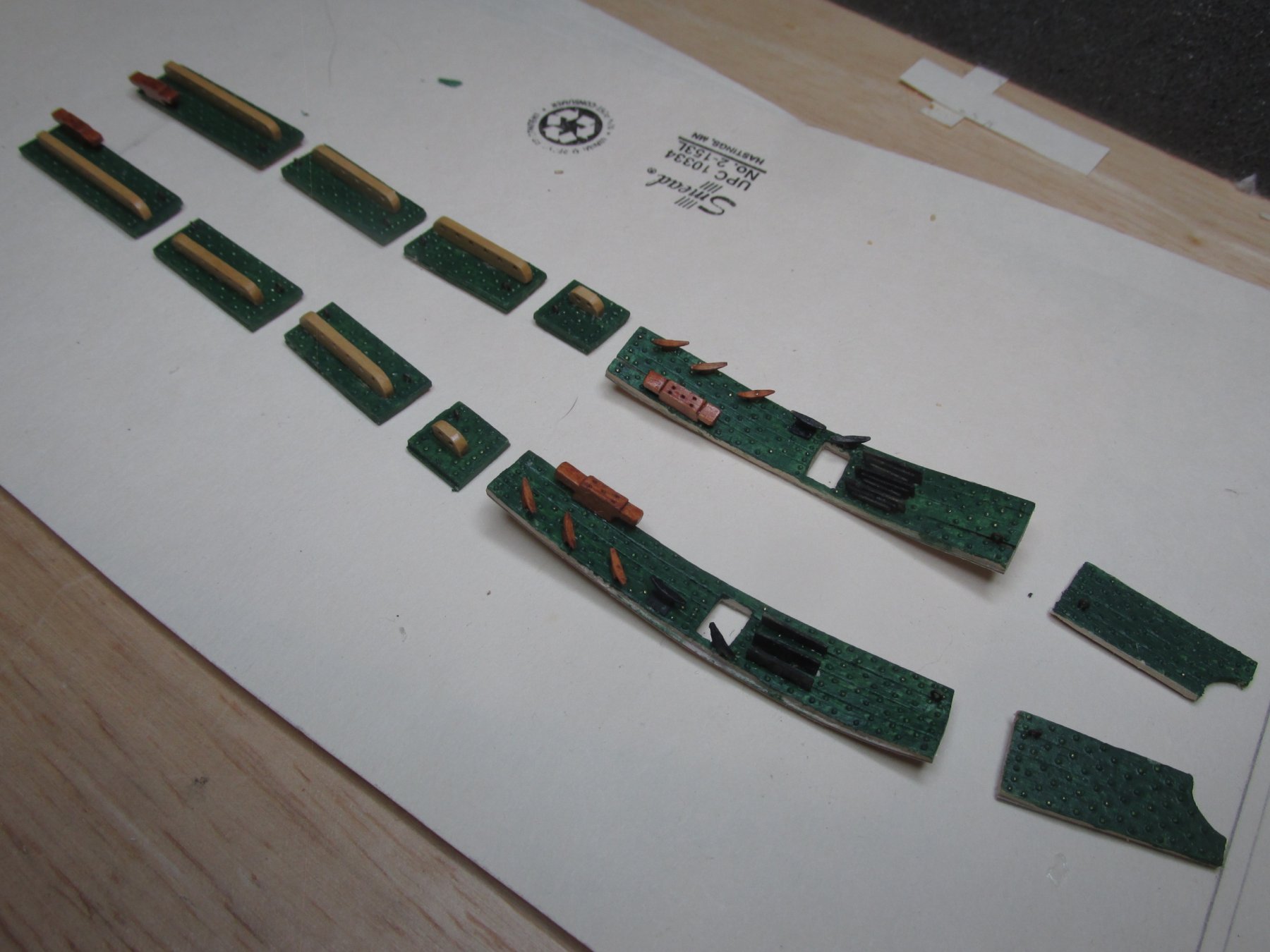
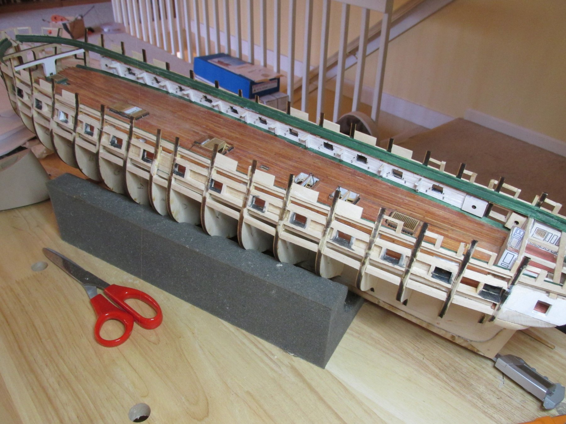
I’ve completed the remaining bulwarks forward of the waist and shown here unpainted and dry fitted with the pin rails. I then painted the bulwarks and assembled and glued their associated parts. All the fabricated bulwarks are shown in the last image.
- J11, CaptainSteve, Ryland Craze and 5 others
-
8
-
Yes, I am slowly (what else is new?) continuing to make the spar deck bulwarks. I also had personal business, as well as visiting Mom in Florida who turned 101 early this month of June.
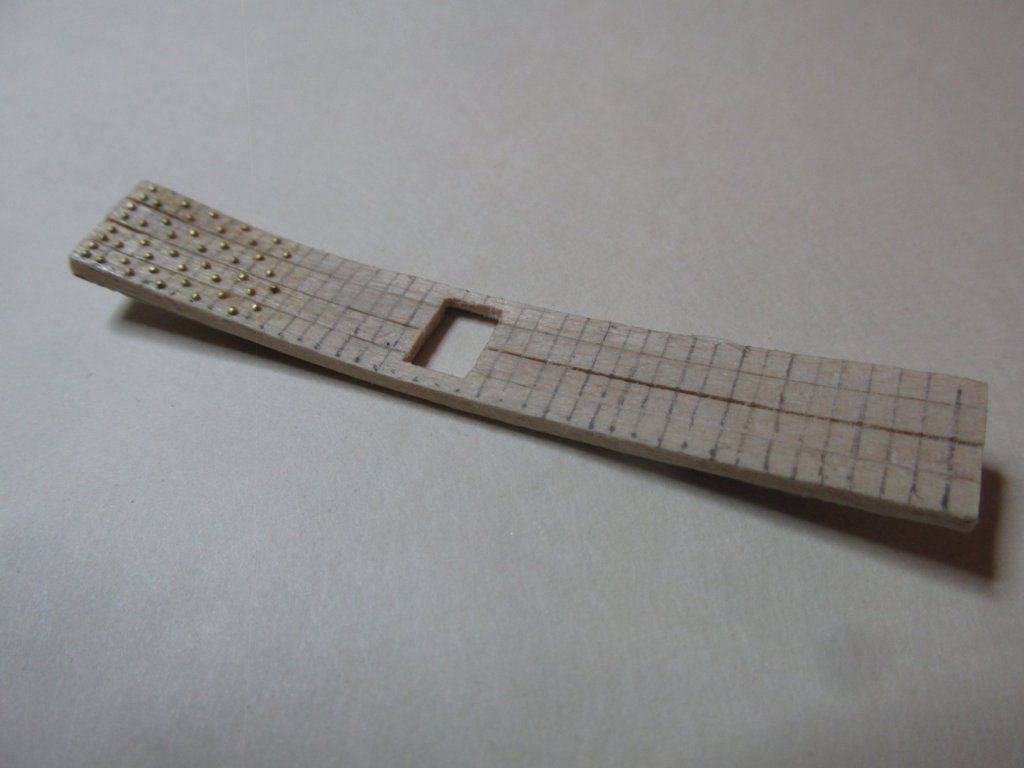
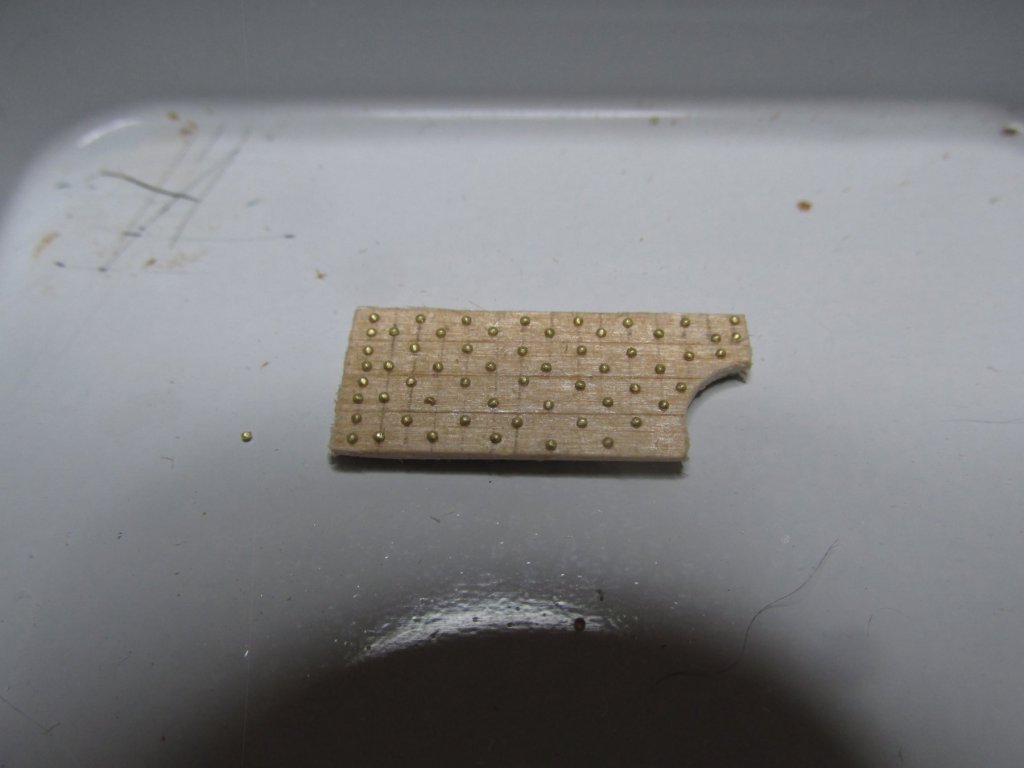
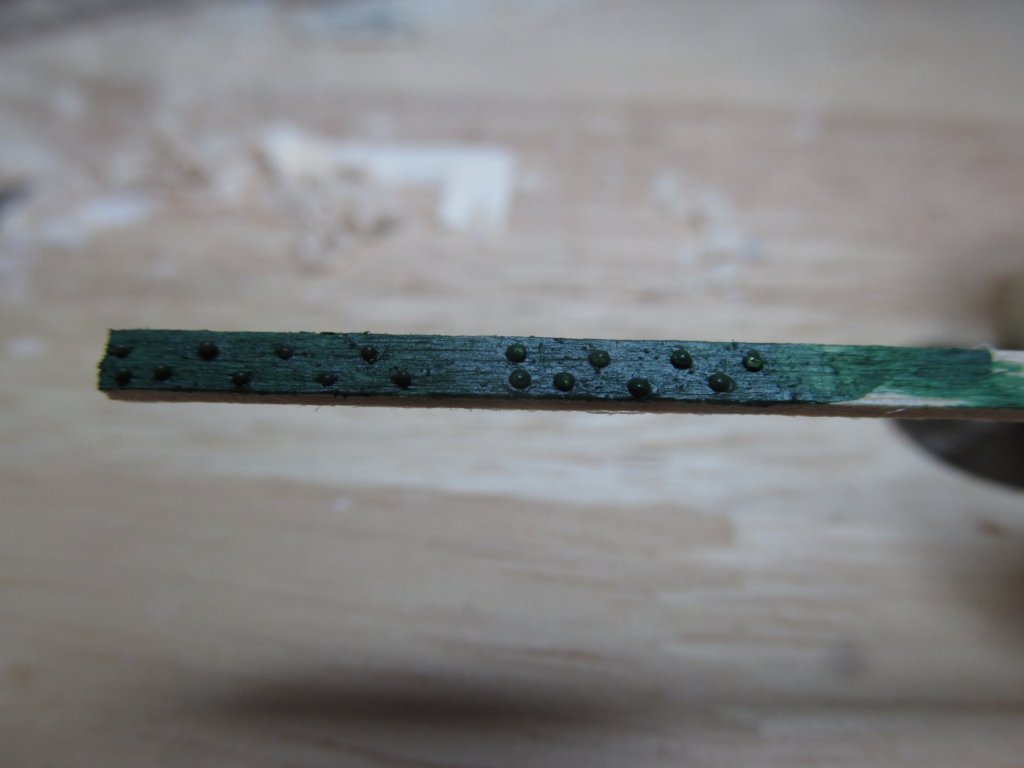
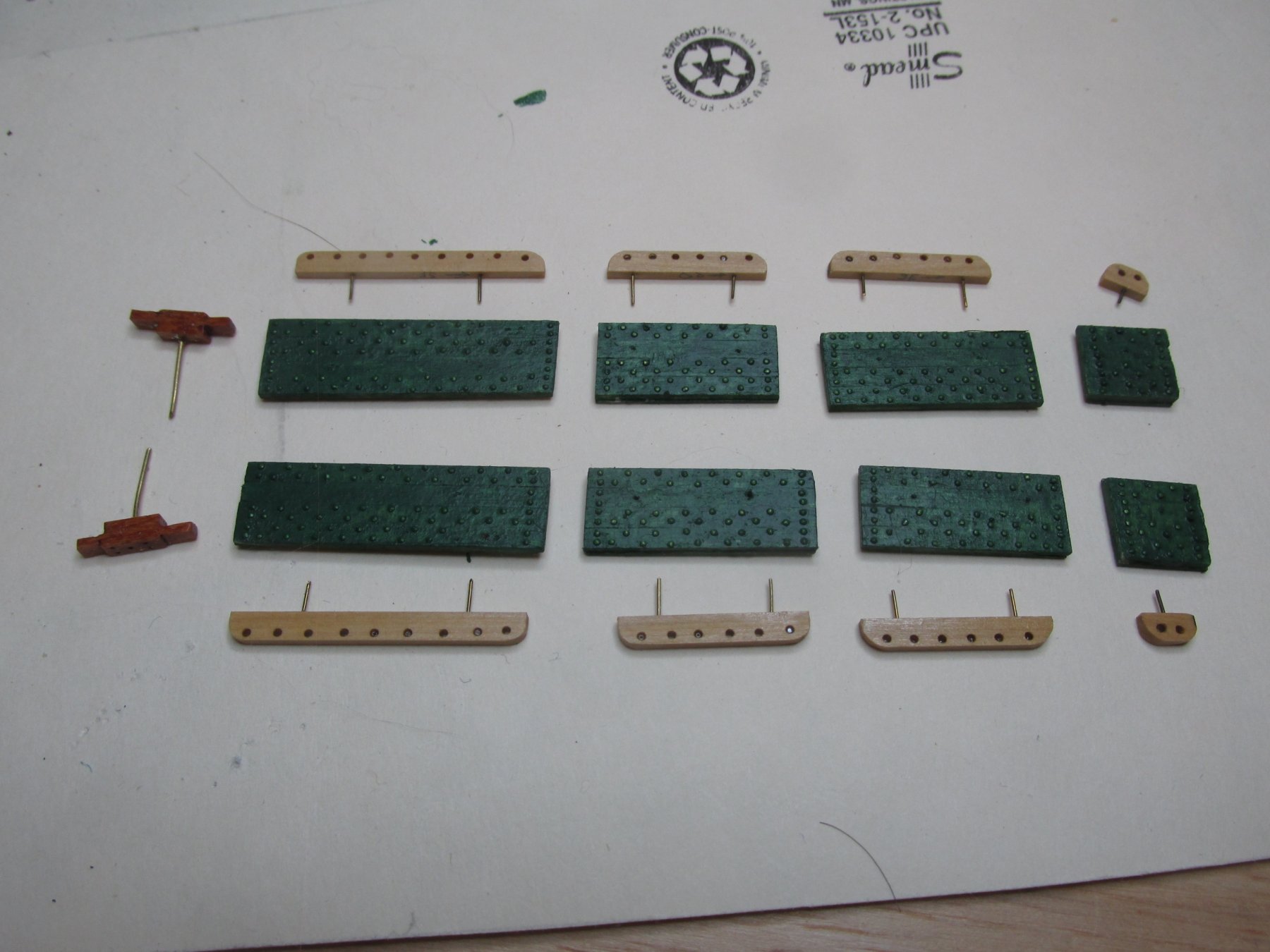
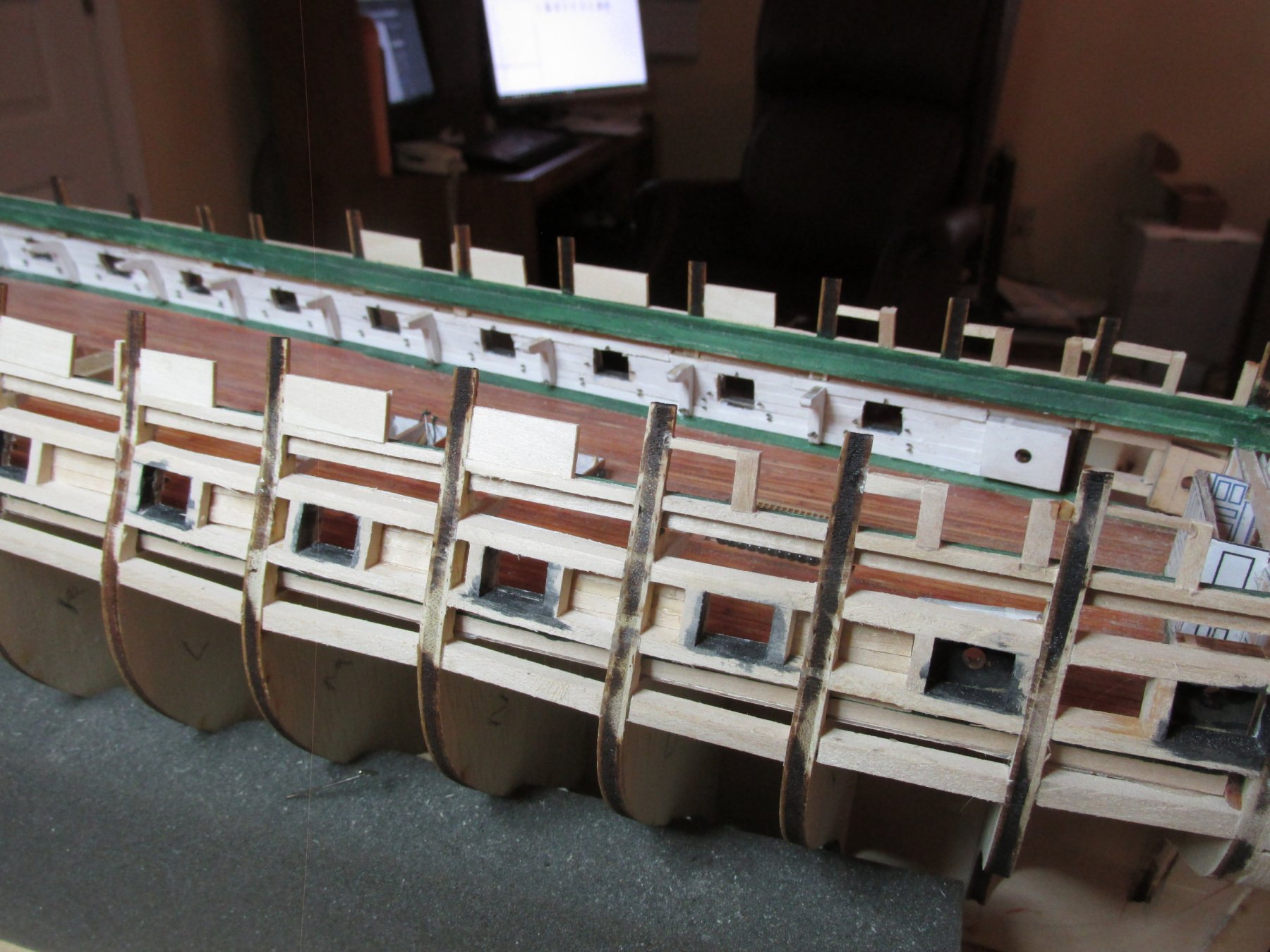
Most of the remaining bulwarks required pin rails. Continuing with my use of boxwood for any bare wood fabrication, the pin rails were made from 1/8” x 1/16” strips of boxwood. Because I know where the pin rails are going to be attached on the bulwarks, I left gaps devoid of simulated bolt heads where the pin rails were to be installed. Notice that the belay pin holes are close to the edge and not centered on the board. That is the way they are supposed to be as shown on the plans and as pointed out in Robert Hunt’s practicum.

-
And I thought I took a long time (7 years) to build my Rattler. Good to see you have the tenacity and stubbornness to finish. Looks good!
-
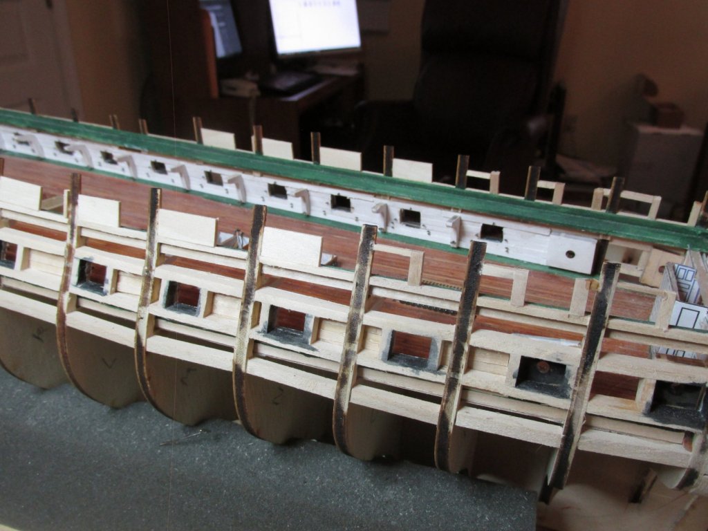
Finally, I attached all the bits and pieces to the bulwarks after removing some strategic bolt heads that were interfering. The second image shows the dry fitted bulwarks in place. For the most part, the remaining bulwarks will need the pin rails and like the gun deck, rigging eye bolts attached.
- Tom E, tasmanian, usedtosail and 7 others
-
10
-
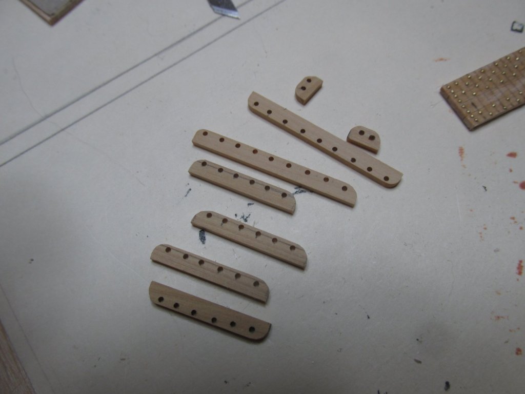
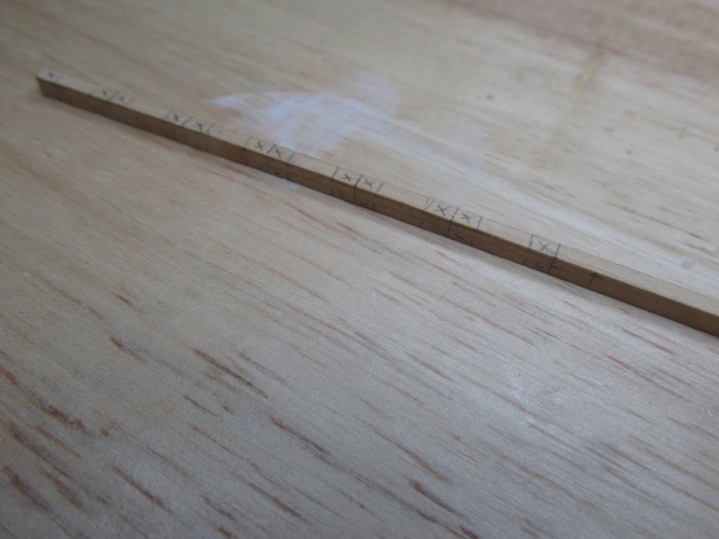
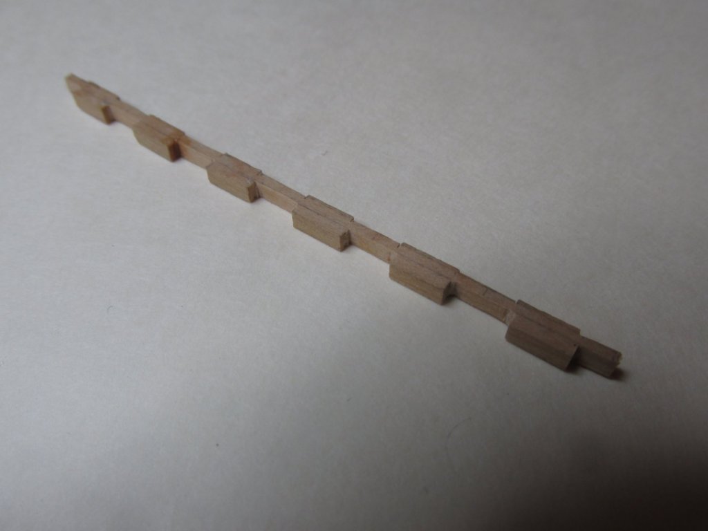
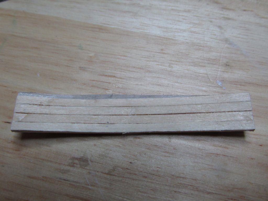
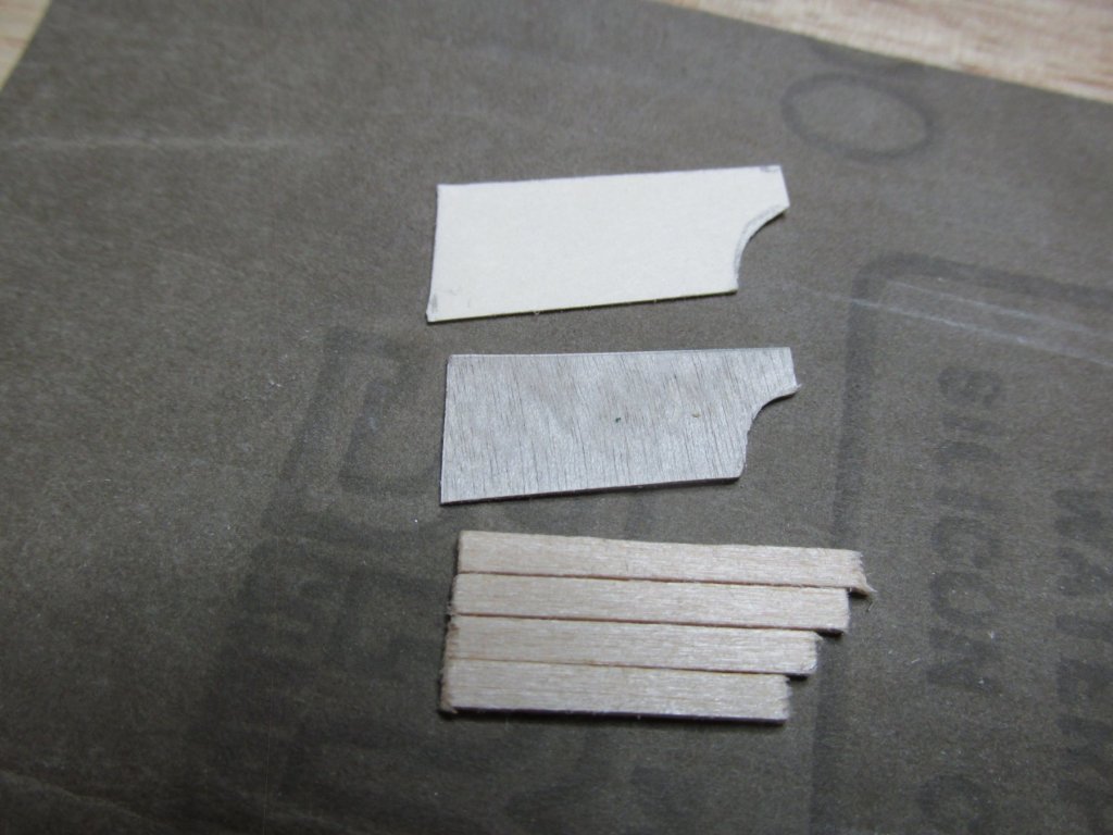
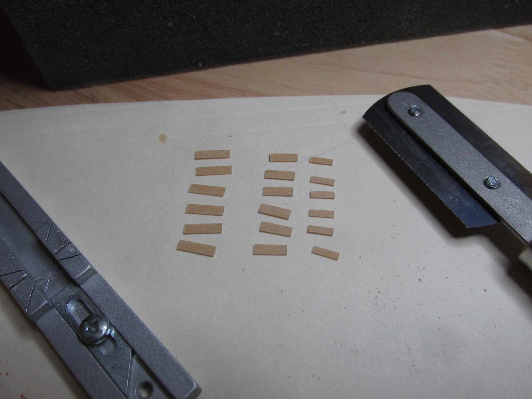
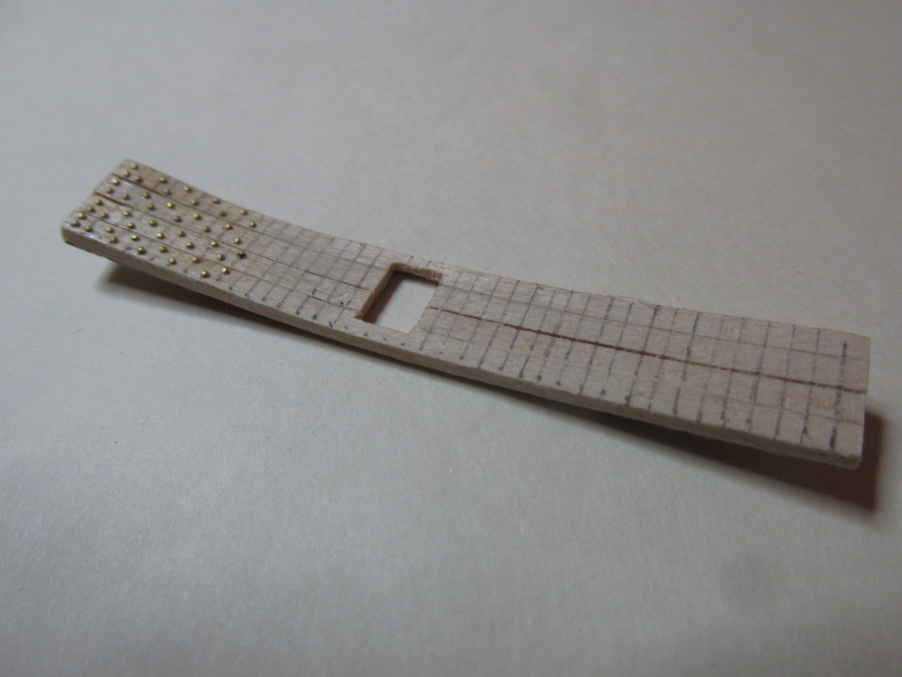
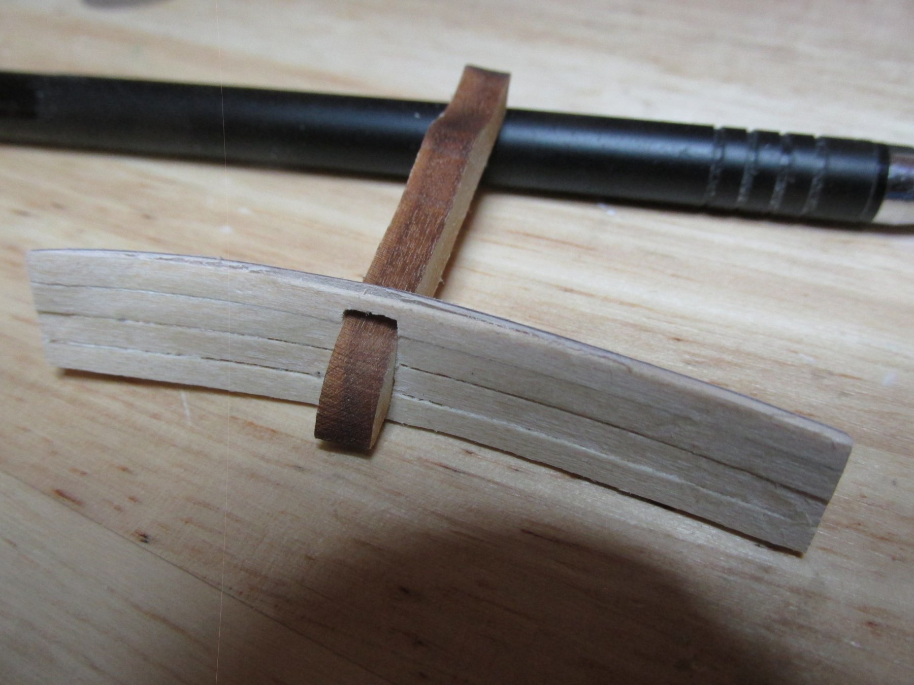
The last items to be fabricated, were the three bulwark steps for each side. Close examination of the actual steps shows they are not simple pieces of wood but have three layers in descending lengths and widths stacked upon each other pyramid style. One step is about one half the width of a bulwark plank. This works out to 3/64” total thickness
Using my Byrne saw, I cut a strip of 1/32” x 3/32” boxwood down to 1/64” x 3/32”. Great saw, that Byrne saw. BTW, all these pieces of boxwood are leftovers from my Rattlesnake kitbash which didn’t use any basswood.
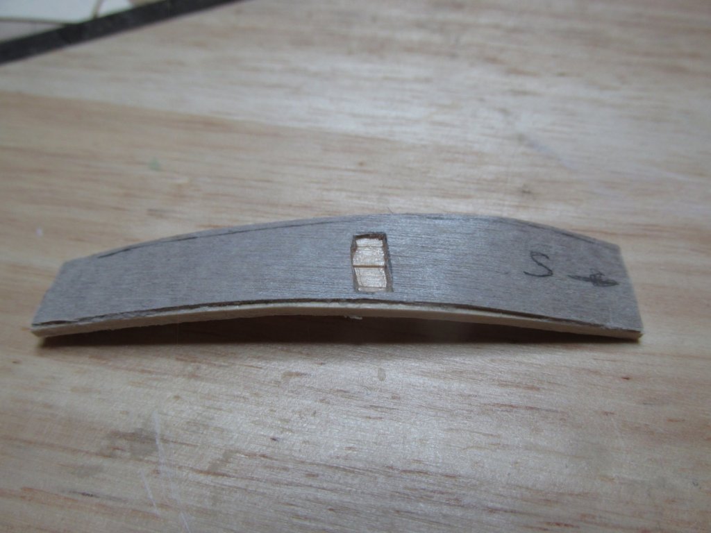
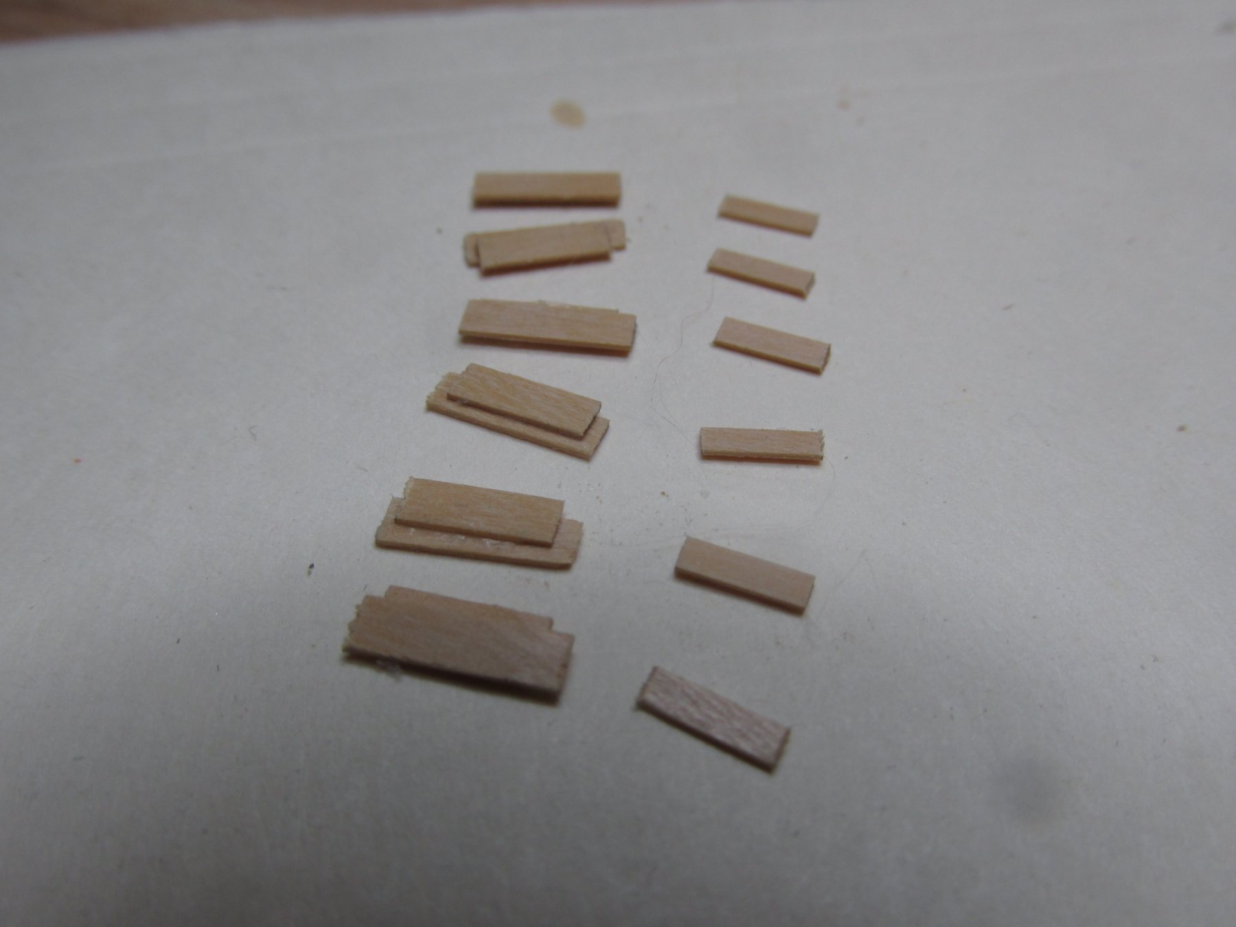
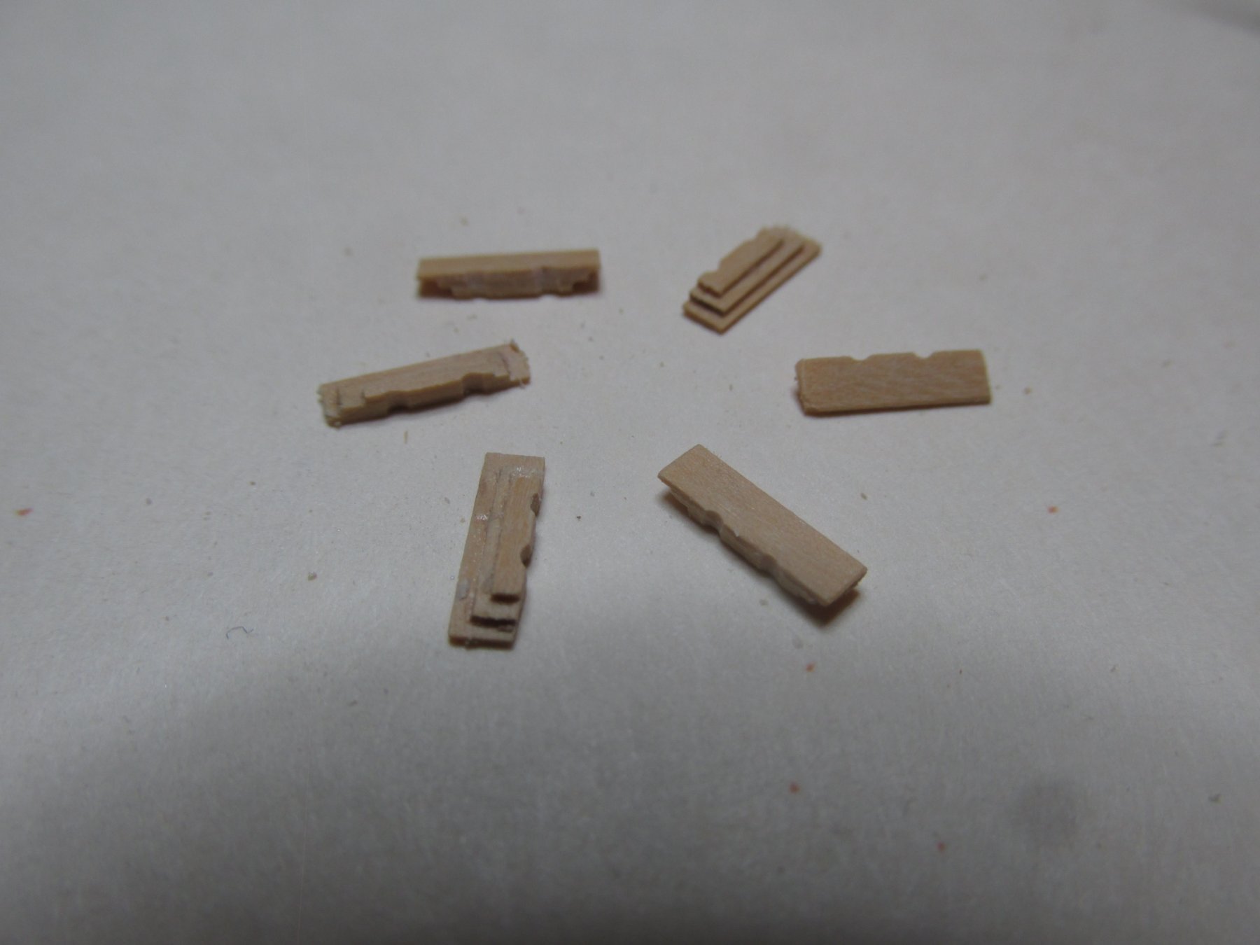
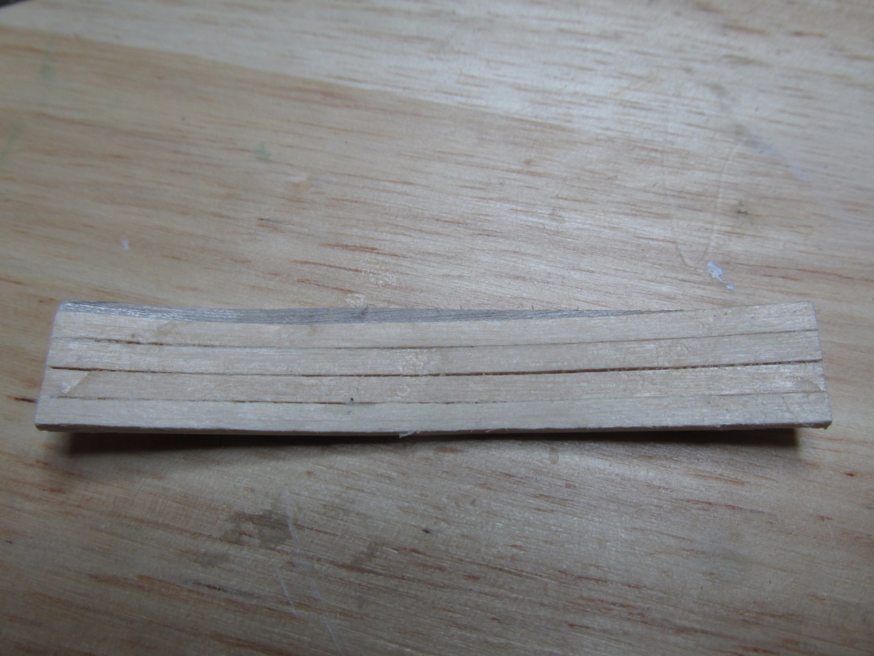
Using the razor saw and its miter box, three different lengths of boxwood were cut for each step. The first two pieces to be stacked upon one another were offset to create the first stepback. The third piece which was a bit narrower was the third stepback. Then, with a sanding block the excess wood from the back of the step was removed. Finally, two vertical channels were filed at the back of the step. What the purpose of these opening was, I don’t know, but they are there, so I made them. No metal installation post was needed as these pieces are not intended to take any load.
Now it’s a matter of attaching all this stuff to the bulwarks and the bulwarks to the hull frame.


- J11, David Lester, CaptainSteve and 2 others
-
5
-
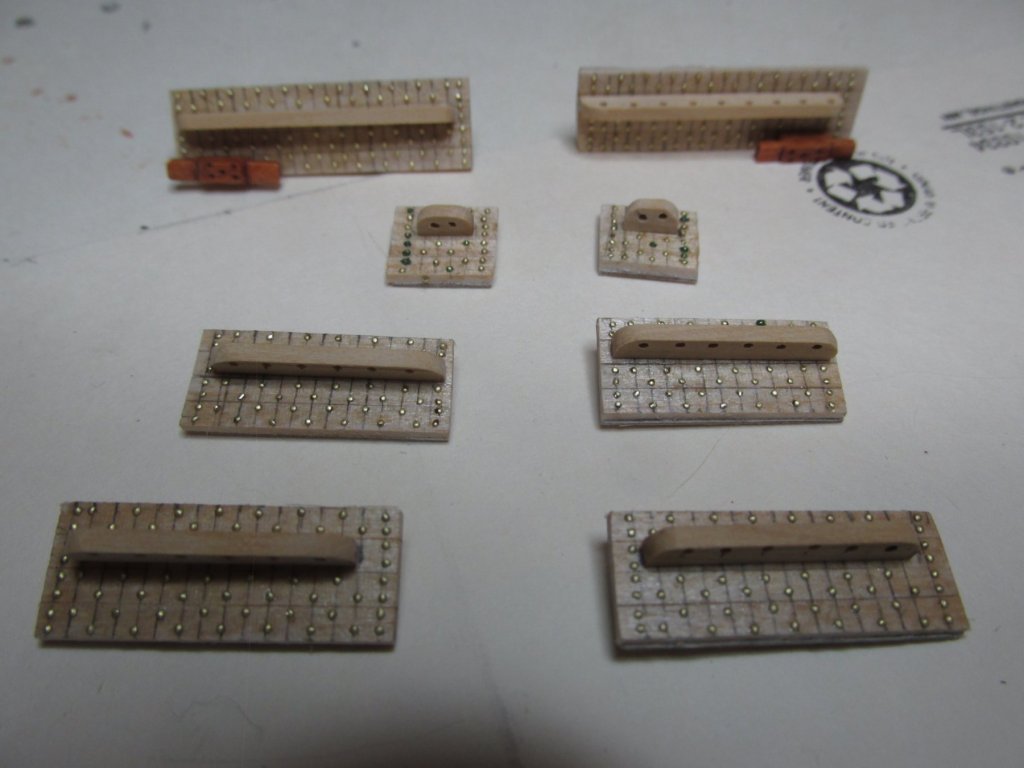
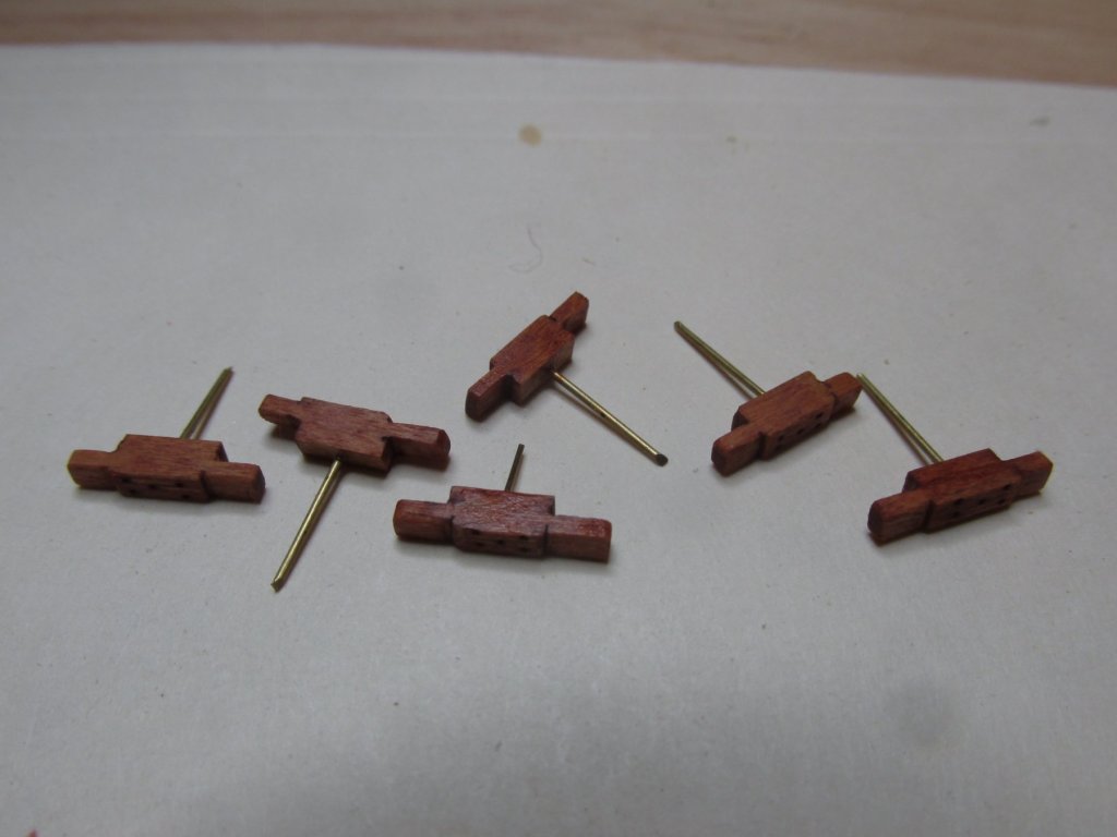
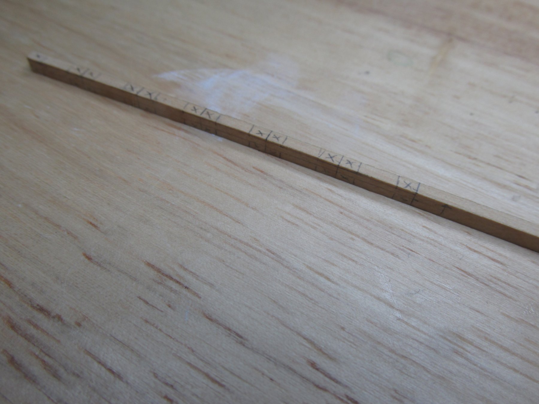
The large wooden cleat was made following the lead of xken’s Constitution build log which meant I made the two required (one for each side) plus four more to be used later. For these I used 1/8” x 3/32” boxwood. Boxwood holds its edge much better giving a sharper result, plus it going to be left as natural wood.
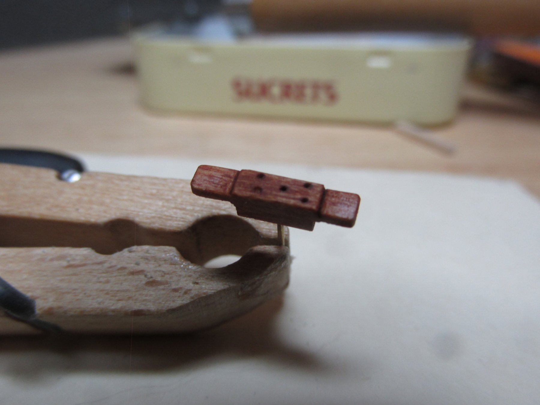
I marked off the required vertical cuts for all six cleats on the one piece of wood which were cut with the razor saw save for the cuts which would have separated the six pieces. The horizontal cuts were made carving out the wood with an X-actor knife. As seen in the image above of the actual bulwark, the large cleat has five bolt heads recessed on its face. Xken simulated the bolts by drilling holes and filling them in with “black” glue. I’ve not heard or seen “black” glue except as epoxy which I was not going to use for such tiny fills. I initially thought I would use bamboo tree nails stained black. As normal, I used a pin to make a starter hole for the drill. Then I thought, why make tree nails, a fine spot of black paint should do the trick, but I didn’t want the paint to soak into wood surrounding the bolt holes. To remedy that, I sealed the wood with the Minwax first. However, I noticed the stain accentuated the bolt holes and made them look black. My job was done. To the naked eye, you can’t tell the pinholes weren’t filled in due to the dark color. They looked perfect.
The cleats were then separated with the razor saw with final filing, trimming, sanding, and staining completing the cleats. The last touch was the addition of a metal installation post to provide added strength for potential rigging.

-
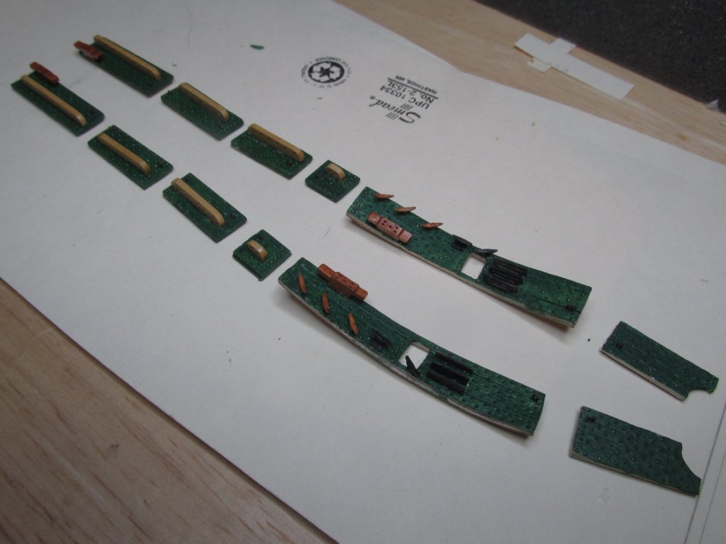
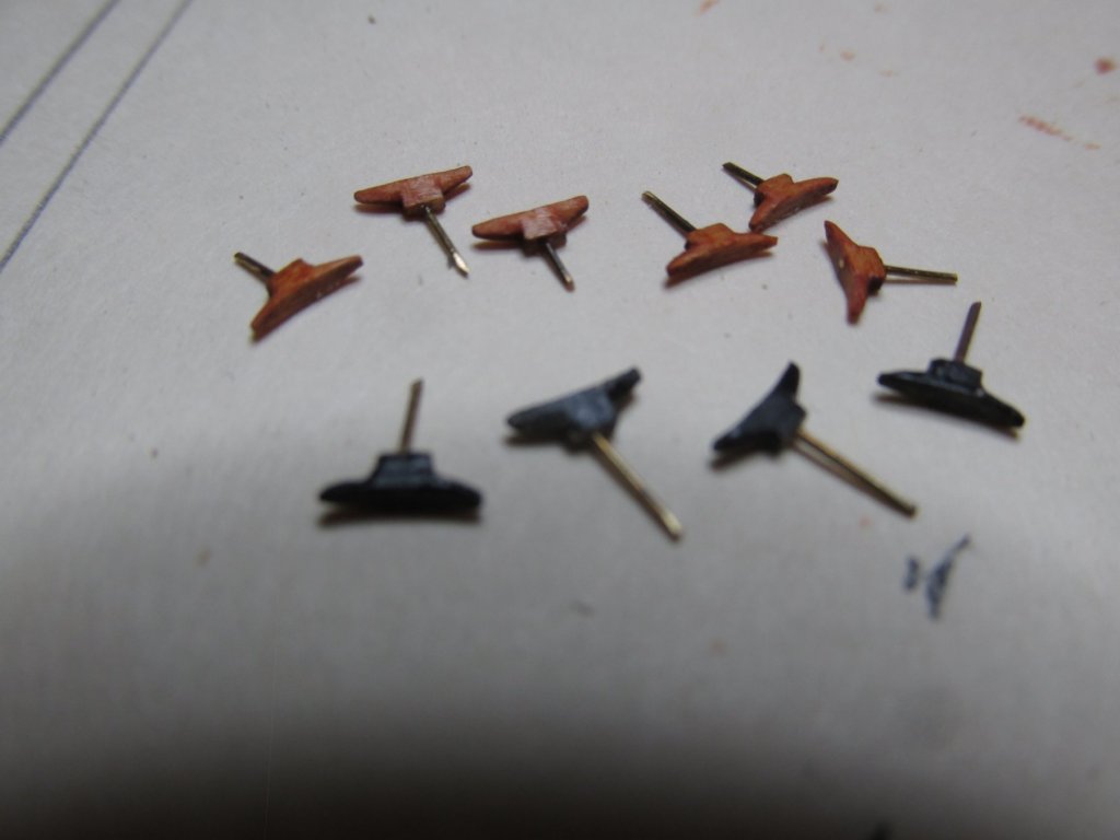
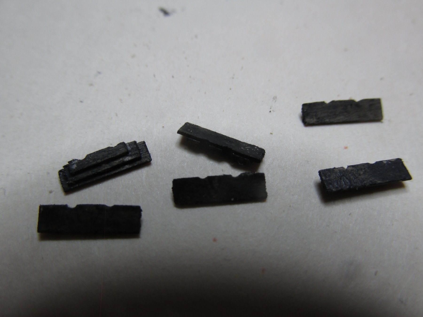
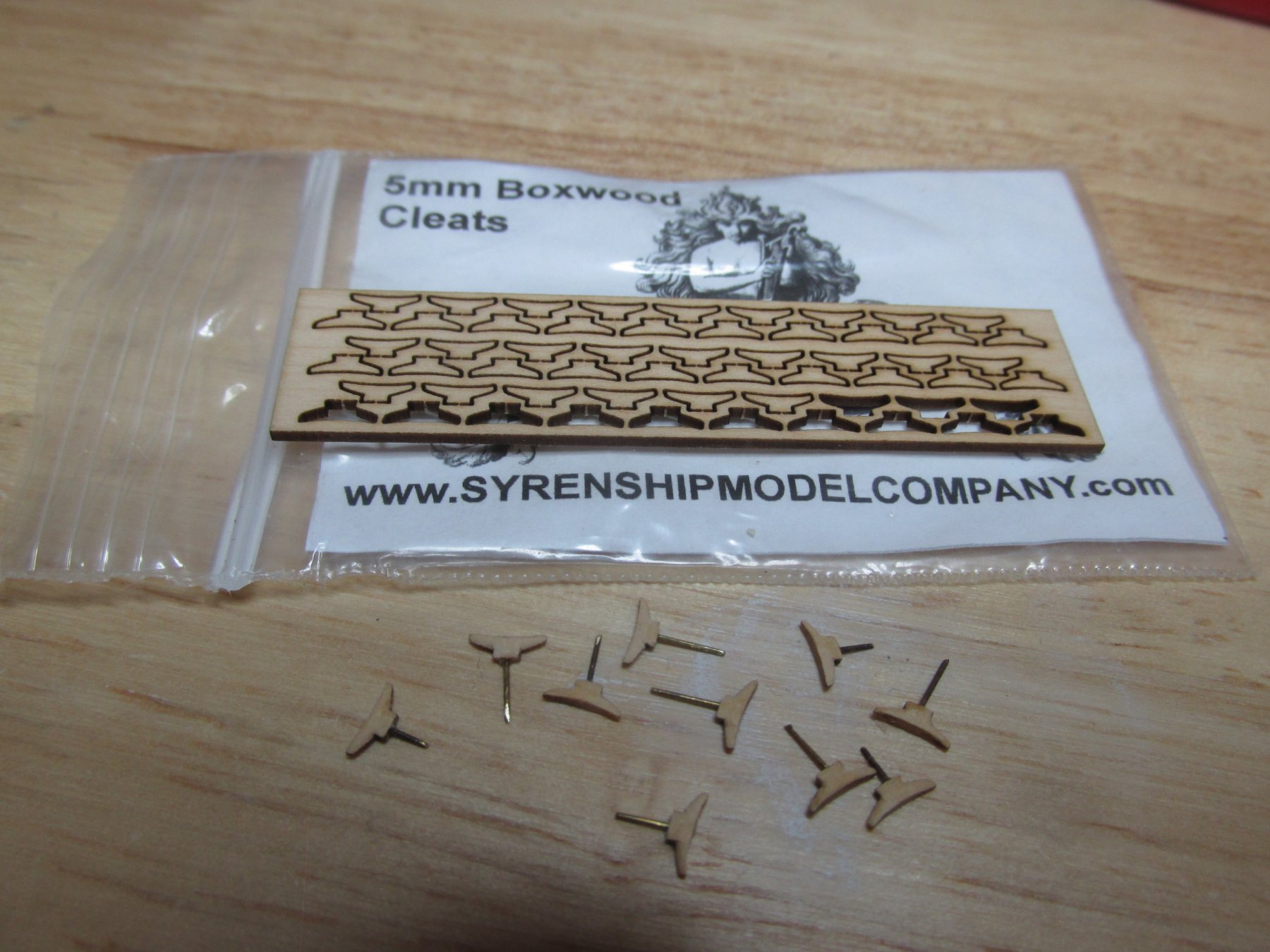
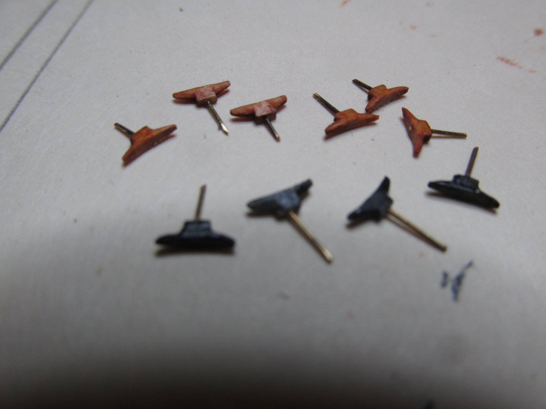
The Syren cleats are really blanks and must be carve to their final shape. For each side, the three wooden ones were stained with Minwax Wood Finish Gunstock 231. The other two Syren cleats were painted black to simulate metal with one cleat to have a base plate made from painted cardstock when installed. Installation posts were added to provide connection and rigging strength. They also act as a fabrication handle. The posts will be trimmed just before installation.

- J11, Geoff Matson, CaptainSteve and 2 others
-
5
-
For each bulwark, there are three small wooden cleats, two small metal ones, and one large wooden one. The small cleats are not supplied with the kit, so I am using Syren Ship Model Company’s 5 mm cleats. The large one, made from Britannia metal, the kit does supply– I think I can do better than that.
-
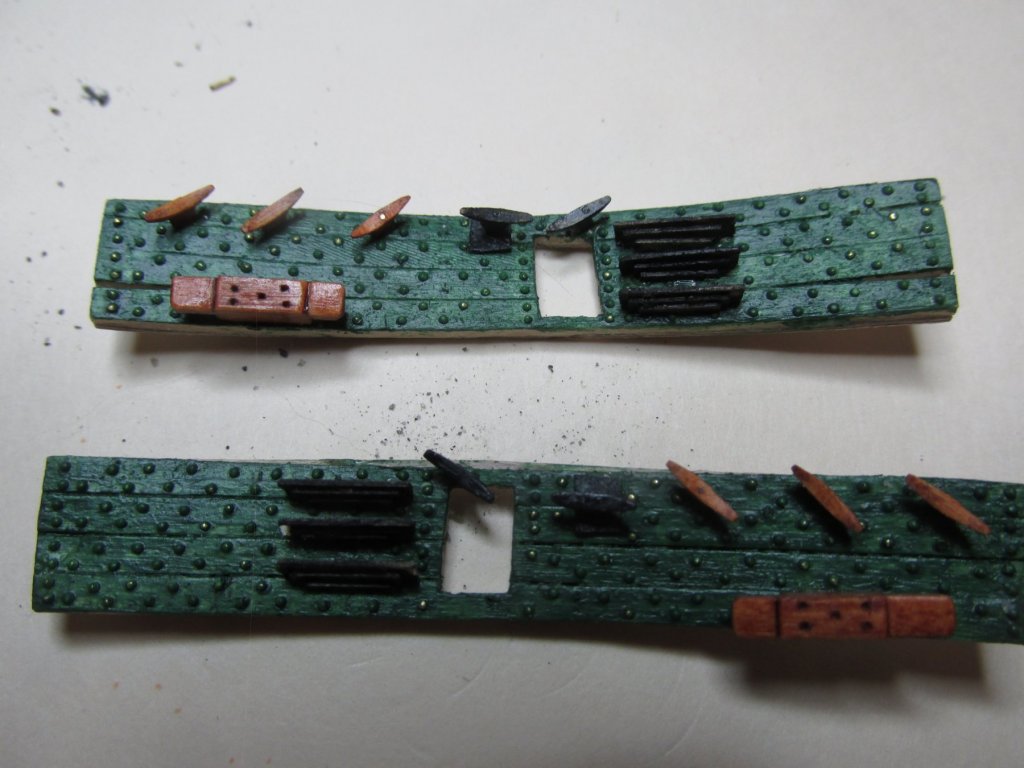
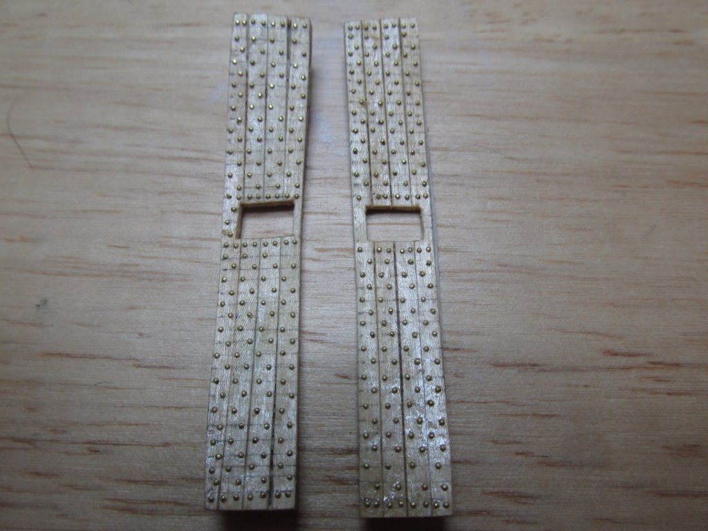
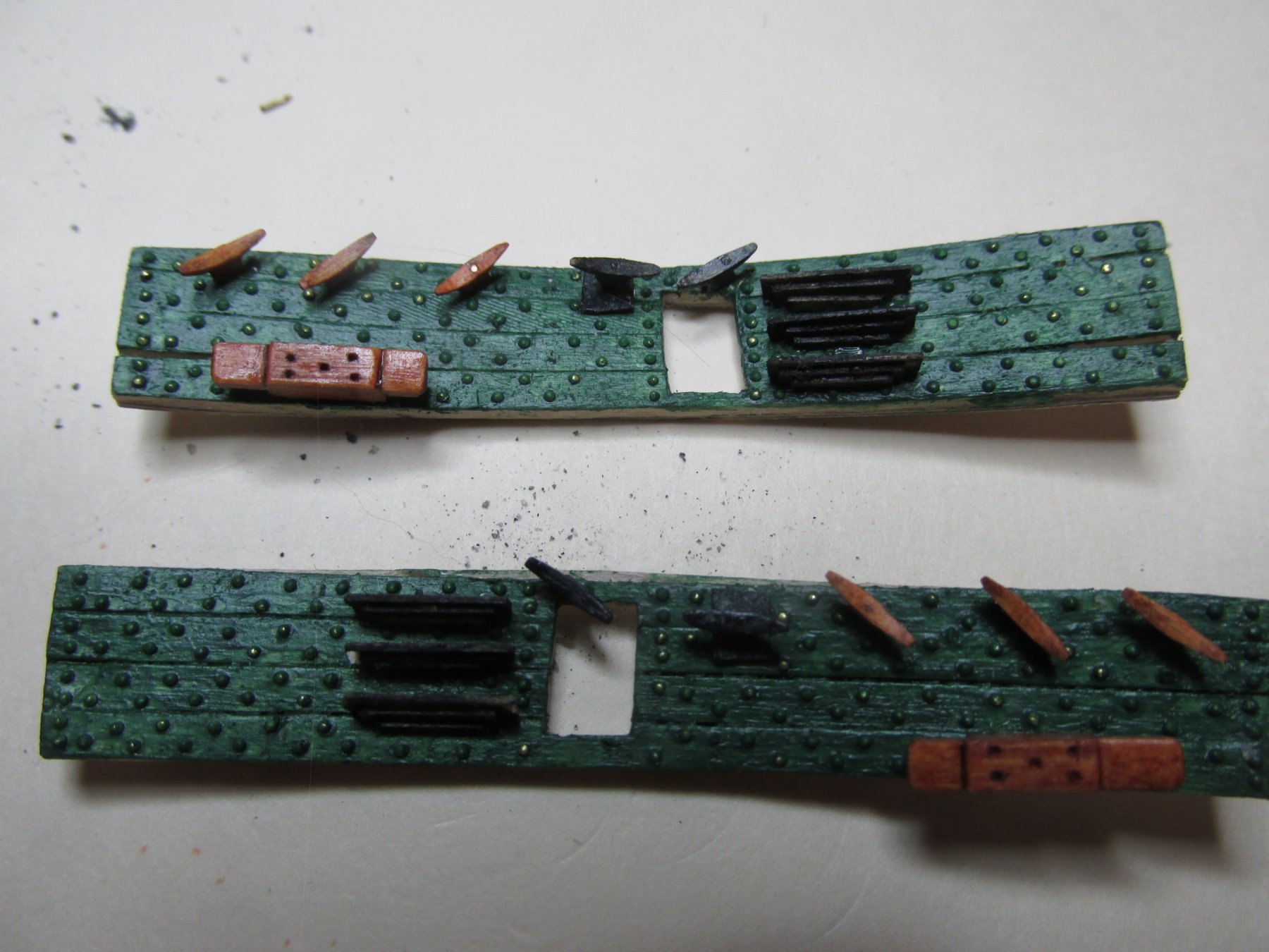
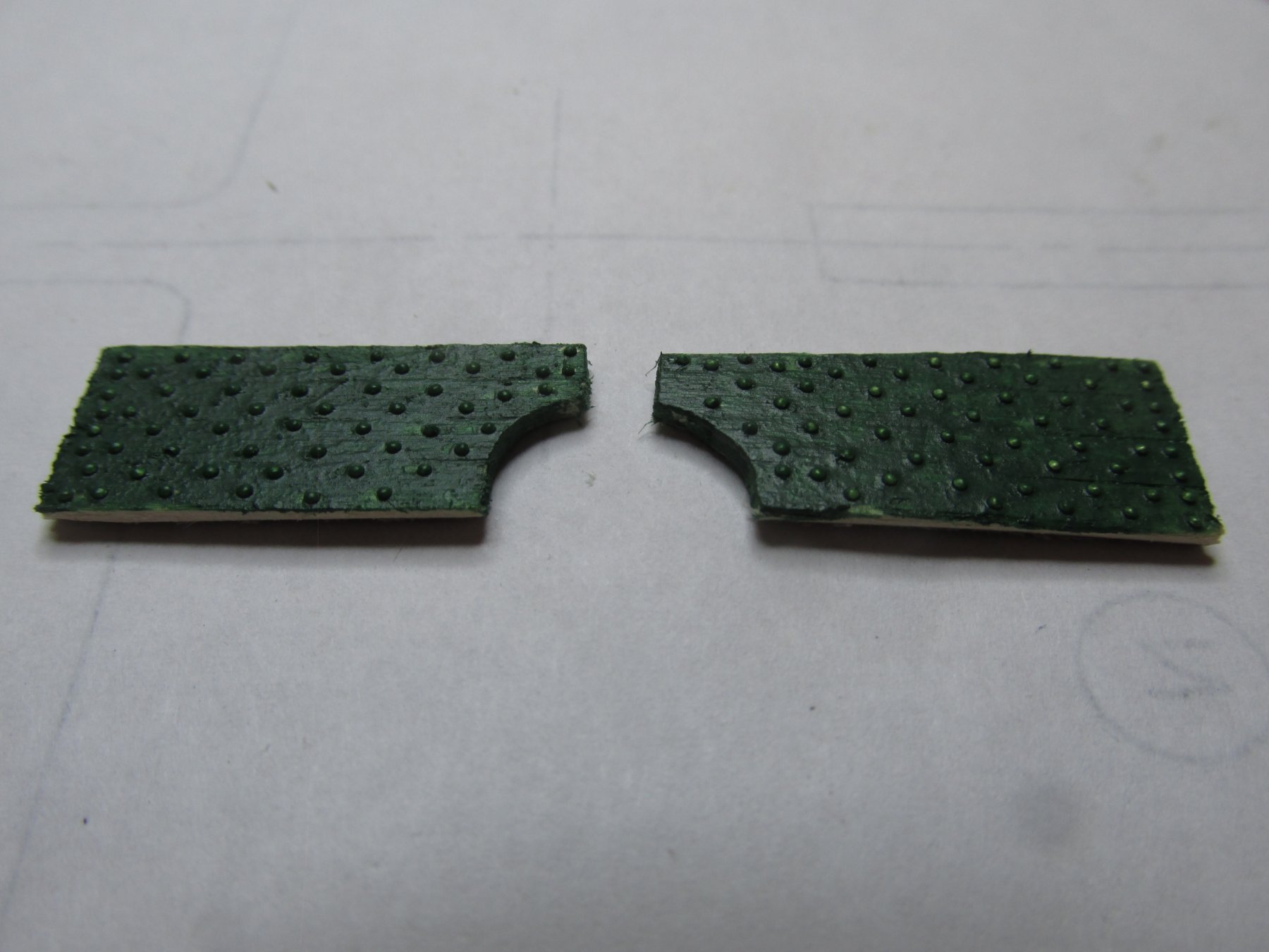
When I started these bulwarks, in order to install the cap rail, then I could work on the quarter galleys and the planking at the wales and gun ports. It’s going to be a bit longer before I get there. Because my bulwarks are constructed off the model, I have the opportunity to install all the bulwark accoutrements such as pin rails, cleats, eyebolts, etc. now while it’s easier. It appears I’ll be building my model from the inside out instead of outside in like everyone else. We’ll see how well that goes. Here is the pair of bulwarks with all the simulated bolt heads.
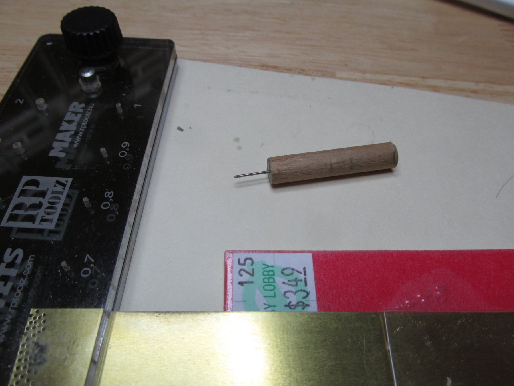
Note: RP Toolz emailed me stating that they would send me two, not one punch. Also, they gave me a link to their Hungarian site where spare parts were available for sale. Still waiting for the package.
-
Things were going just ducky, until, when pulling the punch out from the punch plate, the punch handle separated from metal punch. I use some CA glue to fix that. The metal punch, by the way, turned out to be a drill bit turned around. The cutting part of the drill fits into then punch handle. The other end of the drill bit is ground into the shape of the rivet.
This worked, and I was moving along again until catastrophe struck. The punch snapped in two. This time I could not fix it as one half of the drill bit was still glued into the handle with no way to get it out. It broke flush to the face of the handle. I called UMM-USA, the company from which I purchased the tool from, but they didn’t have any spare punches. I emailed RP Toolz, the Hungarian company that made the tool with my story of my experience with the punch, asking how to purchase a replacement.
They responded right away asking for my address to send the replacement part, free of charge I assume as they didn’t ask for any money. Along with my address, my response stated that I expected to break more punches due the delicate nature of the punch, as these drill bits are quite brittle, plus that I was planning on making approximately 2,000 rivets. I again asked, how do I order more due anticipated breakage. Will see how this turns out.
“In the meantime, in between time, ain’t we got fun,” as the old song goes, I made a new punch. Now that I knew the punch proper was a drill bit, all I needed was the right size drill bit and a handle which I made from a dowel. The drill bit was found just by trying different size bit to see if they fit through the punch plate. After I inserted the drill bit into the dowel, I used a fine file, to round off the edge of the back end of the drill bit as best I could. It worked! Granted, my punch makes a flatter rivet but that’s fine as I trying to simulate the washer and bolt head on the real ship. Flatter is better.

- CaptainSteve and usedtosail
-
2
-
Next, was the addition of the simulated bolts. I got into a rhythm of punching out about 30 bolt heads (a.k.a. rivets) at a time, and then applying them into position with Wipe-on Poly and repeat.
-
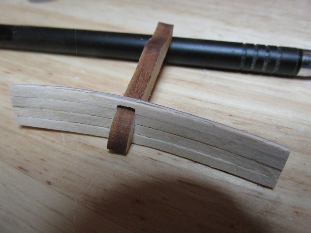
Then, the excess wood was cut away by turning the rudimentary bulwark over and cutting through from the backside of the backing’s cathead opening. Excess wood was filed off the ends of the bulwark and fitted into position to ensure proper fit. The kit supplied cathead was used to fine tune the final shape of the cathead openings. Whether or not I will use the kit supplied catheads, or make my own, remains to be seen at a future date. The rest of the bulwark constructs won’t need extensive bending (I think, I hope).
-
Like the plywood, strips of 3/32” x 3/64” basswood supplied by the kit were cut to the approximate length and soaked. I was able to press the wood to the complex bends for these pieces with my fingers against the now dry and formed backing. The wood strips were glued right over the cathead openings cut into the plywood and left to dry. The markings on the backside of the bulwark backing shown below, indicates that it fits on the Starboard side and the arrow points to the bow.
-
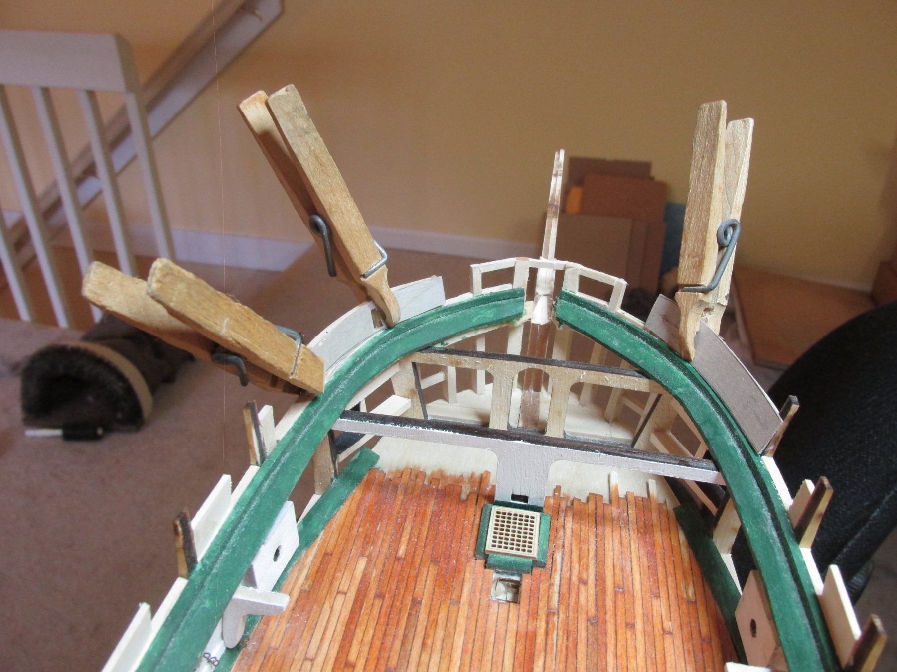
Since I started the bulwarks at the bow with my prototypes, I just continued aft. The bulwarks next to the bow I consider to be the toughest to make…so far. Every piece of these bulwark constructs must be formed into a curve shape conforming to the frame. After numerous false starts I started to make some headway.
As before, I started by making card stock templates for the 1/64th birch plywood backing. After I marked and cut out the openings for the catheads in the plywood, I soaked them in water for a few minutes to make them flexible. The backings were then placed in positioned and held in place with clothespin clamps. I left them there overnight due to its complex bend. The bow curves both horizontally and vertically as the bulwark angles outward around the curve of the bow.

-
Good to have you back
- JeffT, CaptainSteve and mtaylor
-
3
-
Well after spending time away from the shipyard visiting Mom in Florida, I got back installing the framework for the spar deck bulwarks. As usual, I try to follow the instructions when I can, but it dawned on me that there was an easier way to make these. The top part of the bulkheads is no more than 1/16”. Instead of forming a frame with small pieces and trying to align every, I could a single wide piece of stock basswood 1/16” thick. It was easier, went faster, and seemed to work. You will notice that I was working from the stern, forward and you can see the change.
-
You make sound so simple
-
Keith - I did look into the transfer rivets. The main problem I had with them is that they are designed for model railroad use and as a result, the rivet spacing is way too close together. Also, flexibility of use on ship models was limited.
Ken - I was aware of these beautiful mini rivets but not of the MSW members' ability to purchase them in bulk packs of 1000. I saw the posted price of 50 for $6.00, which if other people's estimate of the number bolt heads required as 3000 is correct, that would have meant I needed to lay out $360, hence my brass punch, which cost me around $80.00. One sheet of brass costs $3.50 and I can make thousands of punch-outs. Any idea what the rivet bulk pack cost is?
Thanks for looking in guys, Jon
-
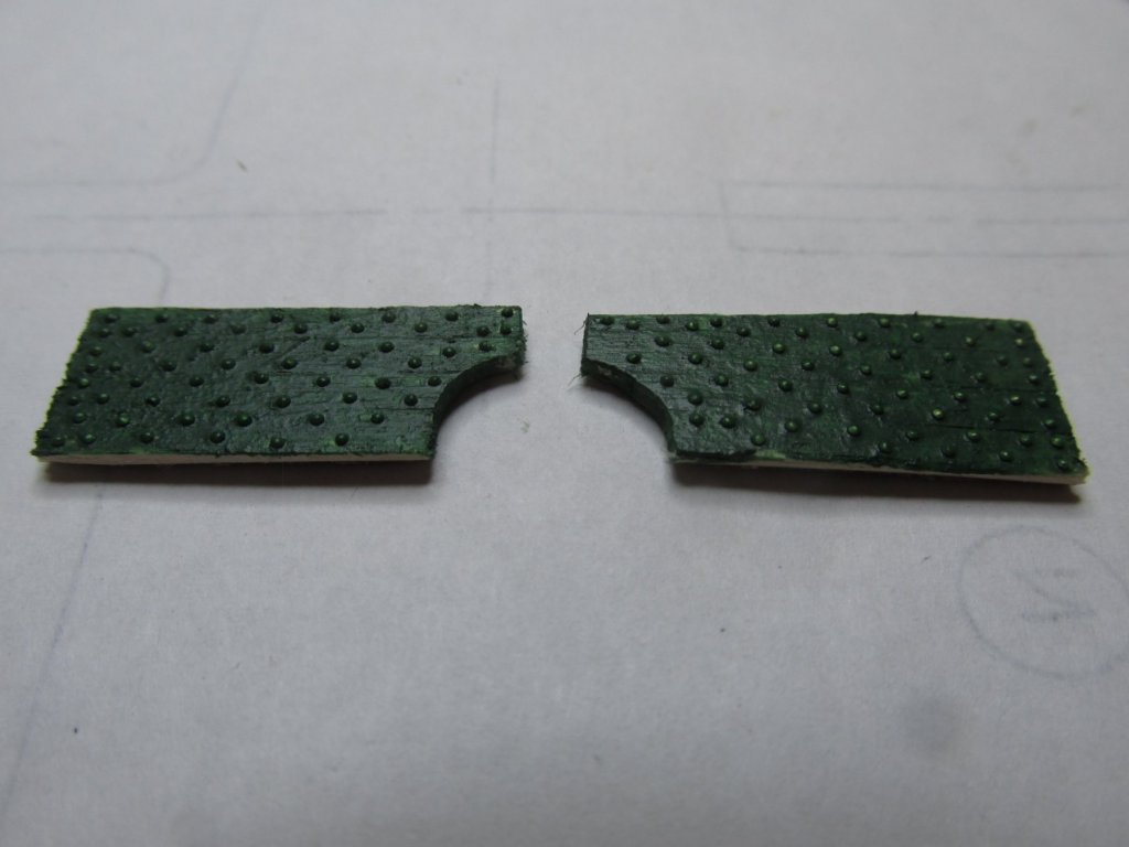
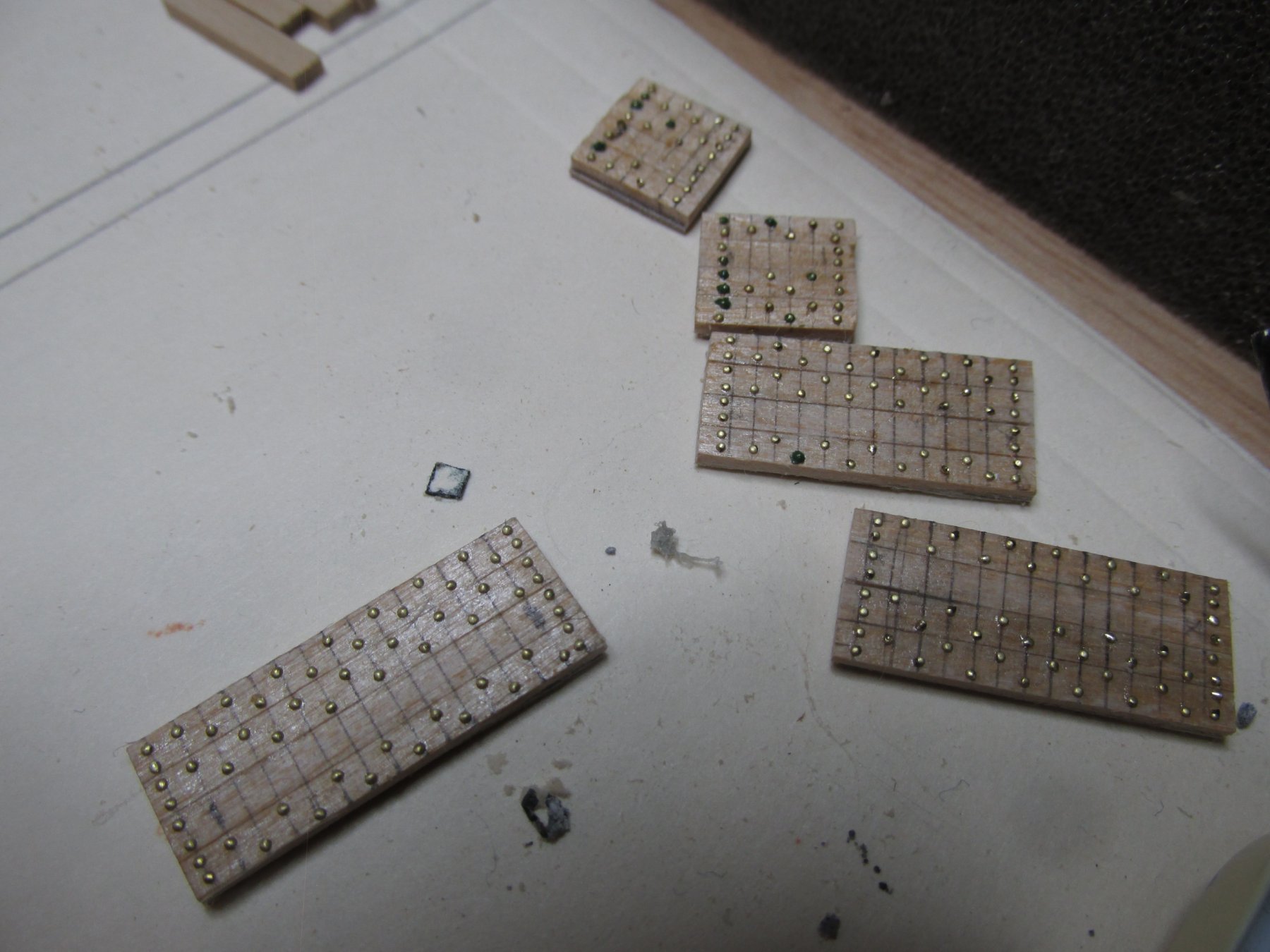
I started with the bulwarks that surround the bowsprit. I made templates out of card stock and transferred the shape to the 1/64” plywood backing. Once the plywood was cut out and fitted to the bow, I glued the planking to the plywood. The plywood was then trimmed. Then I punched out approximately 100 pieces of 0.6 mm brass. The bulwarks were marked with parallel lines 1/16” apart as instructed by the practicum. Using a small brush, Wipe-on Poly was applied in the area where the brass punch-on was to go, The brass punch-outs were placed individually, one by one, into position with the damp brush and X-acto blade. Once the surface of the bulwarks was dry, two coats of Model Shipway Bulwark Green were applied.
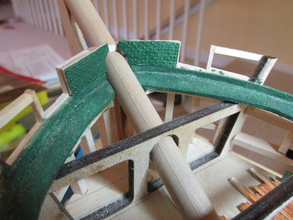
In the last image below, the two bulwarks are dry fitted into position over the partially formed bowsprit. I now plan to frame the remaining gun ports and other openings on the spar deck so that I can continue with the spar deck bulwarks.
- usedtosail, BenD, poundemin59 and 4 others
-
7
-
Installing the bulwarks is another matter. Looking at my gun deck bulwarks, I needed a way to ensure those walls has a smooth for the spar deck as they will be in direct sight of the viewer. Therefore, I plan on using a technique that Mr. Hunt used in his Rattlesnake practicum – a substructure. Some modelers skipped the substructure method and their made their bulwarks directly out of sheet wood made to look like planks. I’m going to use 1/64” plywood as a base and fasten the planks to it. This way I can also make sure all the bolt heads line up the way I want them to. Then I’ll take the sub-assembly and install it onto the model. That’s the plan anyways.
-
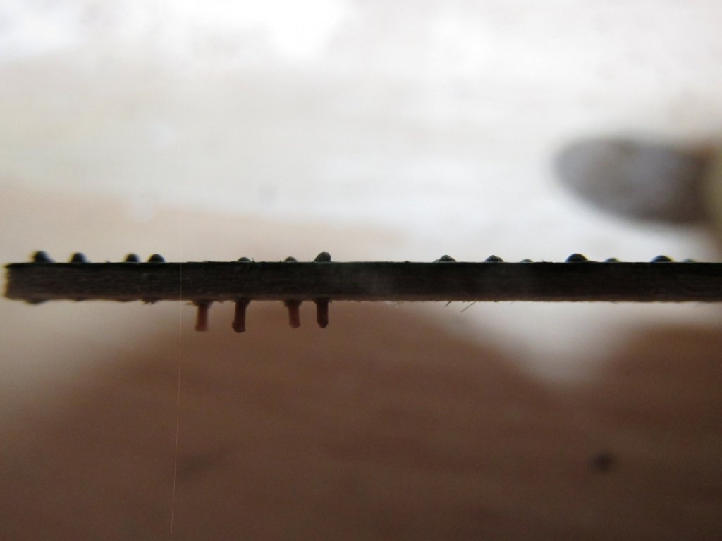
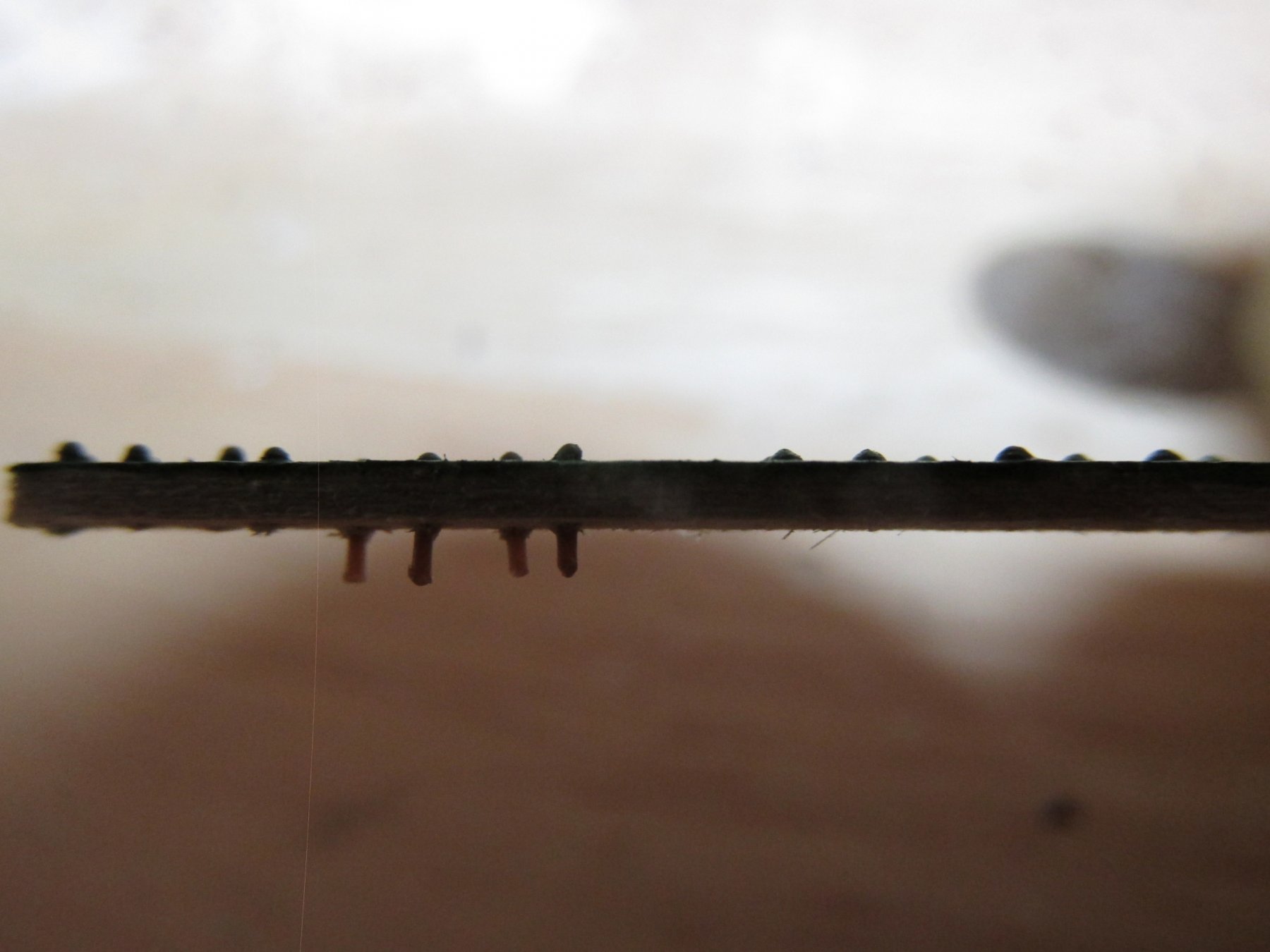
Finally, the surface was painted bulwark green. The paint acted as glue for the plastic rivet and a secondary adhesive for the brass. The results are fairly close, but the brass gave a consistent diameter and height above surface. I am going to start with the brass punch method although I may also use the plastic rivets if the need arises. There is no way I could do this directly on the model. How Mr. Hunt accomplished that feat, is beyond me. In the images below, the left side of the plank are the plastic rivets and the right the brass. I tried showing the height above surface in the second image. Sorry for the poor lighting, but to get these closeups, the camera lens was practically touching the wood blocking my light source. So now I will have to start making over 3,000 pieces of this brass pixy dust. Unfortunately, I still think the results still show the bolt head too high off the surface for both methods, but it’s the best I can do. And to answer your question, yes, I’m out of my frigin’ mind!!
- CaptainSteve, kmart, Geoff Matson and 1 other
-
4
-
The working surface will be coated with Wipe-on Poly and the punched brass will be picked up and placed on the working surface using a small damp brush. Maneuvering and positioning the punched brass into its final position will be accomplished with the point of an X-acto knife. Still tedious, but at least I can re-adjust the bolt head position if need be. I will very nearly match my initial guesstimate of 1” dia. x 1½” with 1½” dia. x 3/8” bolt heads or so goes the theory.
I made a test plank with both methods. Using the plastic rivets, I had to be very careful how I held them in my tweezers. The point of my tweezers was almost the length of the shaft of the rivet so trying to insert them into the predrilled holes can be very delicate. Sometimes the rivet would shoot off the tweezers if the tweezer points moved the wrong way. There is no point in looking for them because they are so small, they are gone…just gone. For this test, I lost 4 of the 9 I originally started with. I found that I had to use the full length of the rivet shaft to get a proper grip to allow me to push them to the drilled holes.
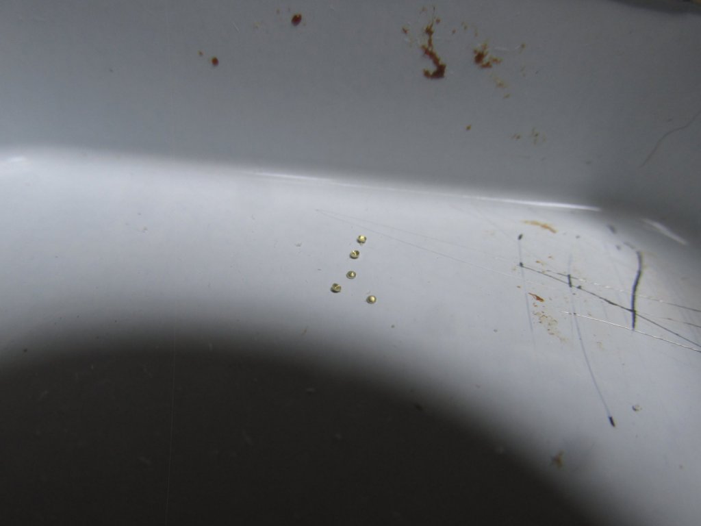
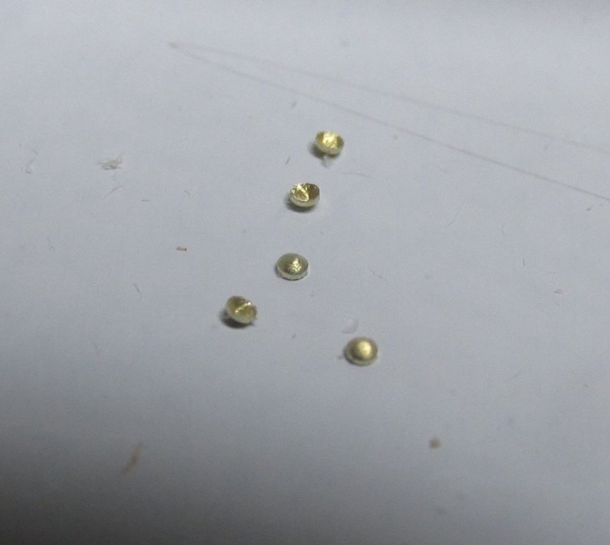
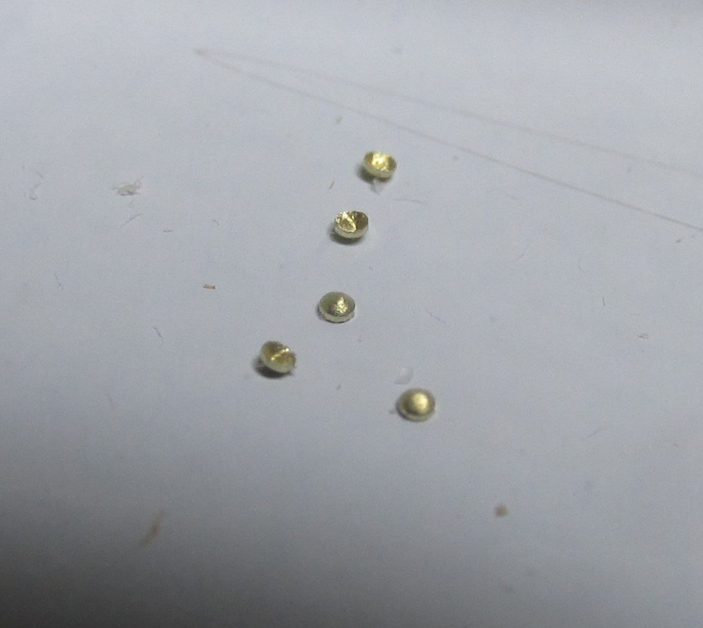
Using the brass, punching out the rivets was very easy but boy are they tiny. There is no way you can pick them up with a tweezer. I thin coated the area I wanted to fasten the bolt heads with Wipe-on Poly and using the same damp brush, I picked up a punch brass piece. Getting the bowl shape so that its convex surface was facing outward was fairly easy, as was positioning.
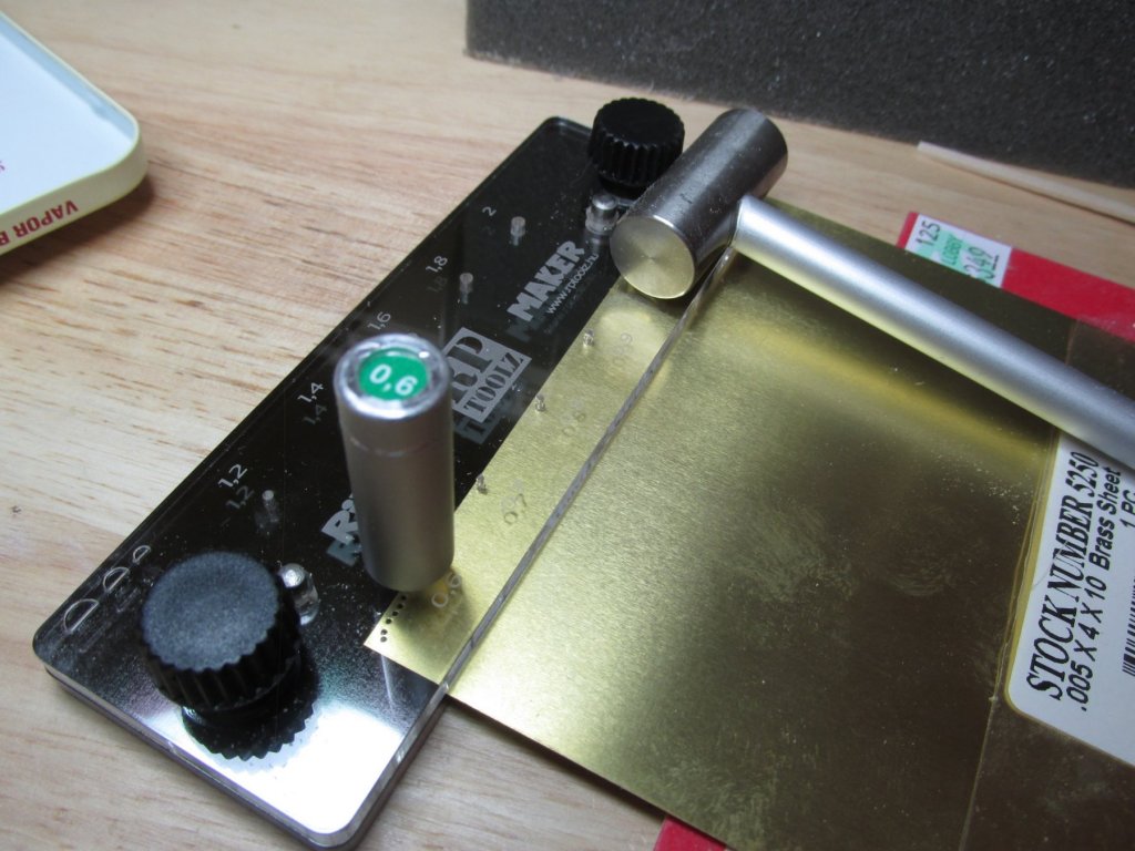
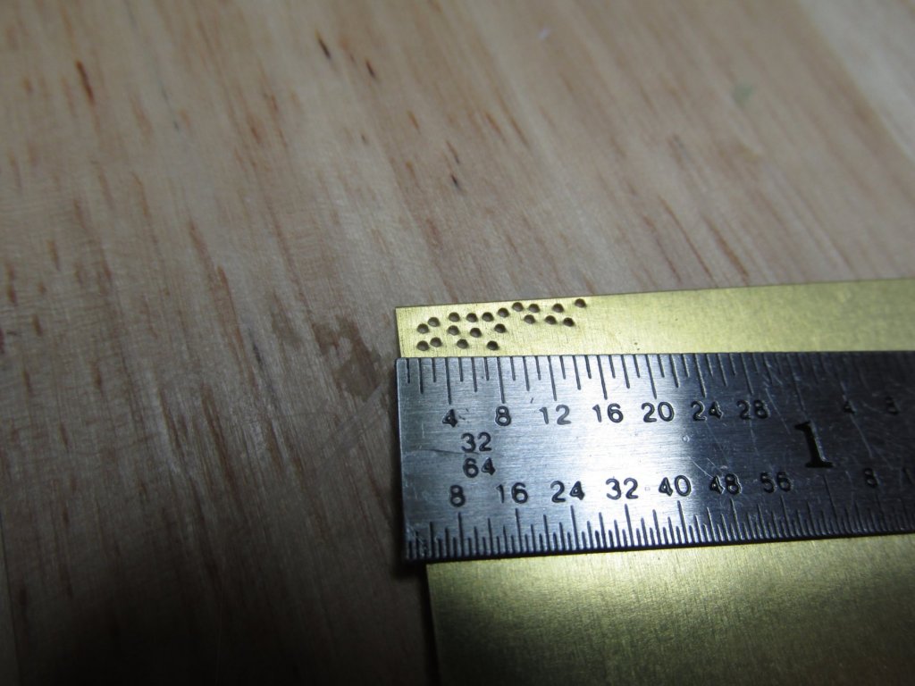
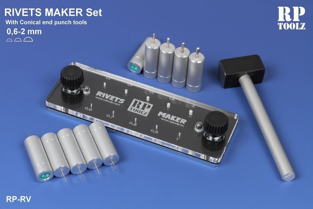
Both processes required the work to be done under magnification. In the images below, is the punch set-up, the brass plate with the punch-out holes, the punched-out brass, and a close-up of the punch-out brass.
-
I ran across a tool, which I hope will solve this problem – a precision punch made by RP Toolz called a Rivet Maker Set which can make a rounded rivet head using 0.06 mm to 2 mm punches. I’ll be using 0.005” brass plate (3/8” equivalent) as the bolt head raw material, and the tool’s smallest punch, the 0.6 mm (0.023”) equivalent to 1½” dia. head. The punch is designed to create a bowl shape punch-out.


USS Constitution by JSGerson - Model Shipways Kit No. MS2040
in - Kit build logs for subjects built from 1751 - 1800
Posted
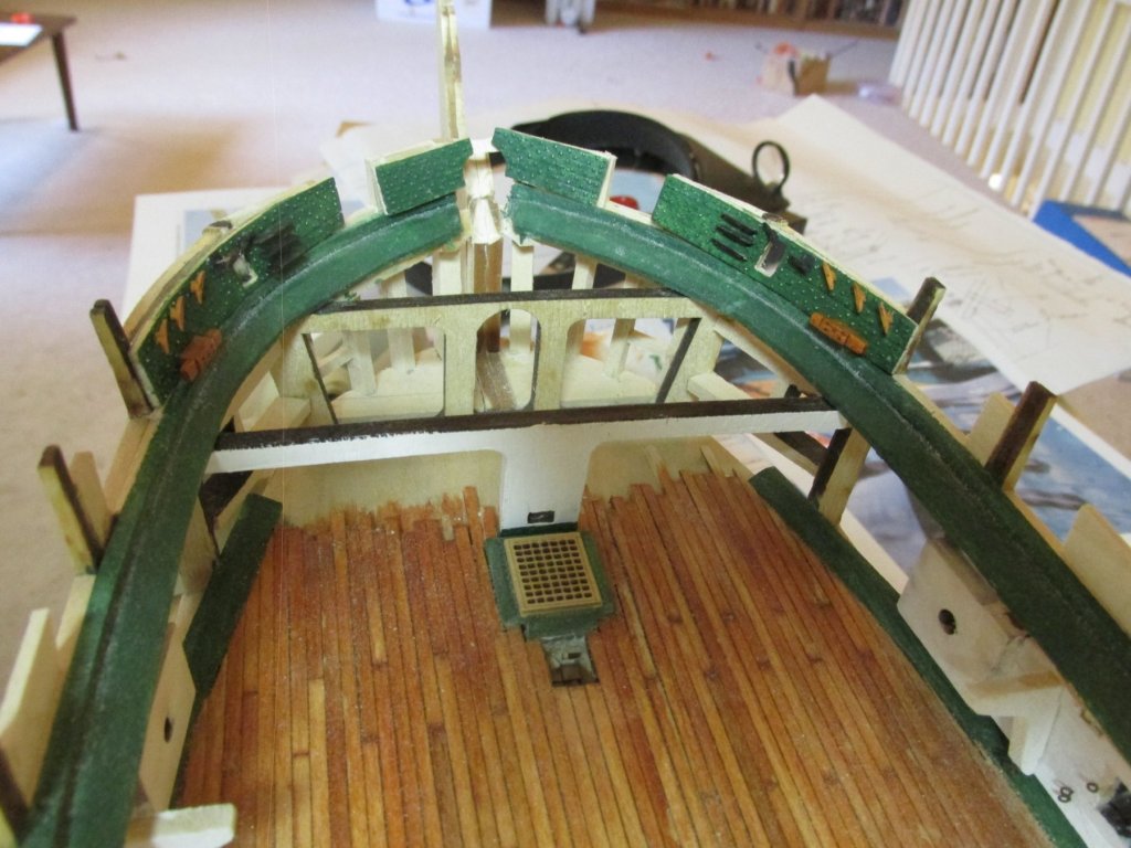
Finally, before I would fasten the bulwarks to the hull, I needed to add the cannon rigging eye bolts to both the bulwarks and the planking just above the waterway. I thought doing that now would be easier rather do doing it later. The blackened eyebolt openings are 3/32” dia. So, they may be difficult to see. Here are all the bulwarks so far (about 1/3) glued into place. The construct continues.