JSGerson
-
Posts
2,646 -
Joined
-
Last visited
Content Type
Profiles
Forums
Gallery
Events
Everything posted by JSGerson
-
 I'll be curious as to how you'll handle the ebony. I've never worked with it before and I understand it is tough wood to work with especially bending. In my case I stained some walnut to get the effect.
 -
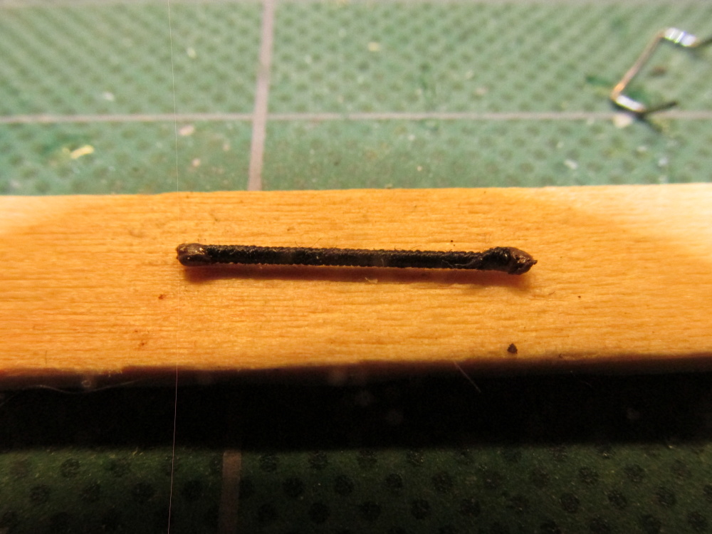
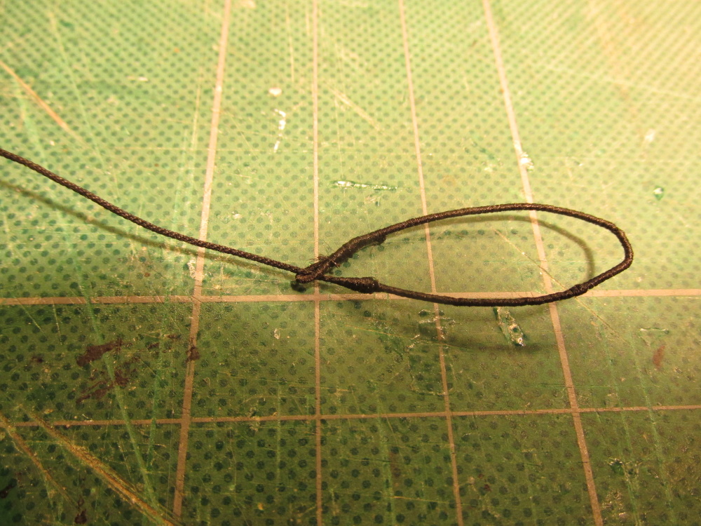
Once the proper length was served, it was cut off from the rest of the wire and the two ends were dipped into some brown paint to represent the leather caps (not that you could actually see them) and lashed to the shrouds. There are still some fuzzys that still have to be snipped off.


- 974 replies
-
- 5
-

-
- rattlesnake
- mamoli
- (and 1 more)
-
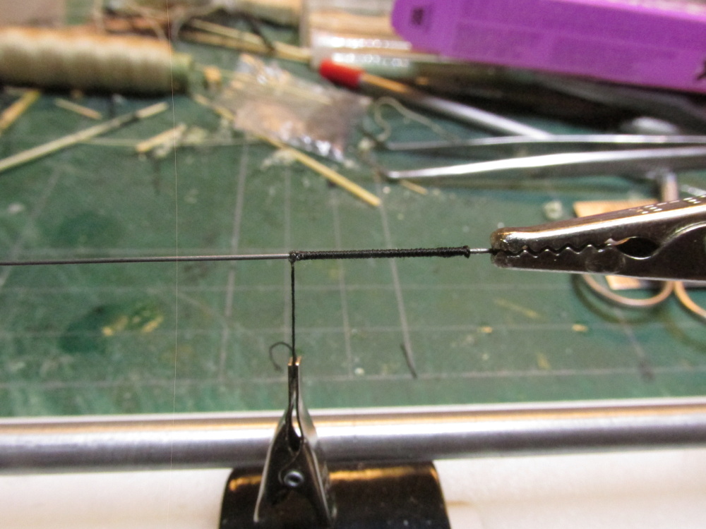
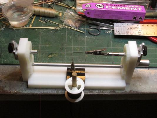
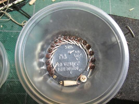
Ratlines – Futtock Staves Following David Antscherl, the next activity is the ratlines. In order to do them the Futtock Staves need to be installed first. According to Antscherl the stave was served rope. According to James Lees’ The Masting and Rigging of English Ships of War 1625-1860 an iron bar was used on some ships. David opted to use served bamboo (made with a draw plate the same as tree nails) in lieu of served rope for stiffness because you cannot see the difference. I went a step further, since you cannot see what material was served, why take the trouble to make bamboo staves? I used music wire which is very stiff and it satisfies Lees and follows Antscherl. The model calls for 0.8mm rope so I used 0.02” (0.51mm) music wire which when served should approximate 0.8mm. My serving machine was able to accommodate the wire and served it easily. The alligator clip in the image is applying tension to the line while some CA glue dries.

- 974 replies
-
- 3
-
-
- rattlesnake
- mamoli
- (and 1 more)
-
I really wasn't suggesting that you make the buckets, but just to look at his technique. You both used the dowel to support the construction. Then again his other stuff looks real neat too.
-
Have you seen Salty Sea Dog's build. He didn't make a pump but he did make a bucket starting at post 335 basically the same way you did. He also made a bunch of other miniatures you might find interesting.
- 481 replies
-
- 1
-
-
- rattlesnake
- model shipways
- (and 1 more)
-
Are those individual slats in the pump barrel body? If so, how did you assemble them? I think they look a bit more realistic than mine. At the time I was following Mr. Hunt's practicum religiously and not looking at the plans closely very much.
-
I found the binnacle a fun little project (comment 179): Yours is beautiful. Is there a reason why your scratch built looks about 50% bigger than the cast metal one supplied by the kit?
-
There is a short discussion of the Horseshoe Plate in one of our forums here: What is That Thing? There is also a link there to Chuck's Confederacy model (see Chapter 8, last page) where he uses a photoetched horseshoe. It does provide a good visual as to what it should look like.
- 264 replies
-
- 1
-
-
- rattlesnake
- model shipways
- (and 1 more)
-
I had the same problem bending those #$%^& ribs. I've been thinking it might have been easier to cut out the ribs (and more of them) from airplane plywood or boxwood directly to shape and skip the bending. You would have ended up with a stronger frame and planking would have be easier. That is assuming you knew how to shape the ribs in the first place so you could cut them out.
-
Question: Those horseshoes are lovely but would you actually see them once you copper plate the hull?
-
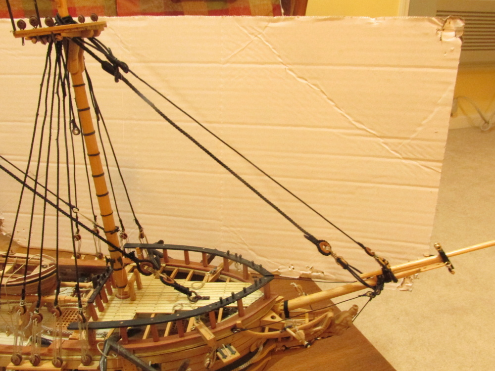
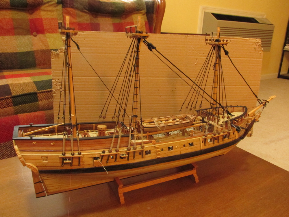
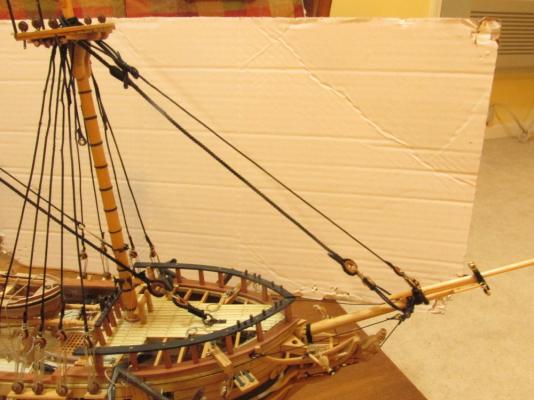
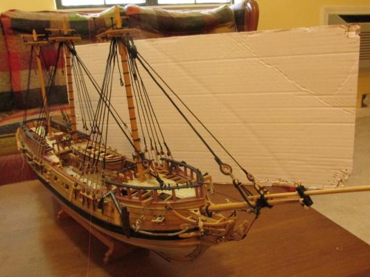
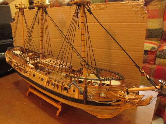
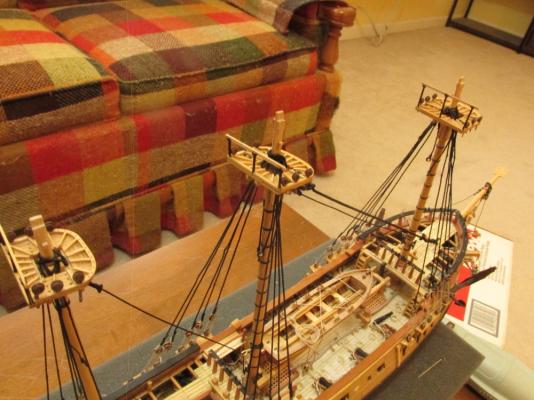
Bowsprit jib boom (previously made earlier) and the Fore Preventer Stay installed

- 974 replies
-
- 6
-
-
- rattlesnake
- mamoli
- (and 1 more)
-
The can ring pulls would be a perfect subject for your other log, Kit-Basher's Guide To The Galaxy
-
Scott - Thanks for the praise. Martin - Oh I'm sure there many more little traps like that still to come. I just hope I ketch them early enough so that the "fix" won't be catastrophic.
- 974 replies
-
- 2
-
-
- rattlesnake
- mamoli
- (and 1 more)
-
Very nice. It may be a small, cheap model kit, but it still takes a lot of skill to build right. I wouldn't let the "blotches" on the inside bother you. When was the last time you saw a pristine working boat? It just makes it more realistic. It's not a flaw, it's an attribute! BTW, I like those oarlocks.
-
Fortunately this meant I only had to cut open a few eye splices and lashings, remove the stay from the mast and re-install them properly once the damage was repaired. I didn’t have to reconstruct the complete stays from scratch. The Fore Stay was completed without and problems (as far as I know) and installed. The Fore Preventer stay will be installed once the bowsprit jib boom is installed.

- 974 replies
-
- 7
-
-
- rattlesnake
- mamoli
- (and 1 more)
-
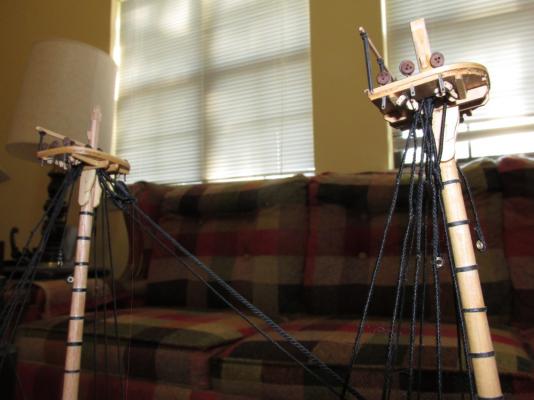
Fore Stay Back to the remaining stays. The Fore Stay was under construction, i.e., making the mouse, eye splices, and heart when I realized I screwed up on the Mizzen stay, Main stay, and the Main Preventer stays…bigtime. In trying to assemble as much as I could off the model, my lack of experience reared its ugly head only I didn’t recognize it at the time. I had looped the stays to engage the mouse first and then attached them to the mast. The only way that was possible was to thread them through the opening destined for the upper masts. It was just a mind block that this was the opening for the upper mast. There was no way for the upper masts could now fit. Examples of the Mizzen mouse and Main stay:


- 974 replies
-
- 2
-
-
- rattlesnake
- mamoli
- (and 1 more)
-
Scott - I'm blind as a bat. I wear trifocals all the time (wearing glasses since I was 7) and when I work on the model I add a clip-on eye loupe. I've heard all kinds of stories about doing those ratlines and none of them favorable. I still have some work to perform on the bowsprit but after that I will have to take the plunge and work those ratlines. Wish me luck!
- 974 replies
-
- 1
-
-
- rattlesnake
- mamoli
- (and 1 more)
-
The deadeyes were blackened the same way as before and put in place. I have been advised that they should be glued in place but I’ll decide if that is necessary when the rigging is attached.
- 974 replies
-
- 5
-
-
- rattlesnake
- mamoli
- (and 1 more)
-
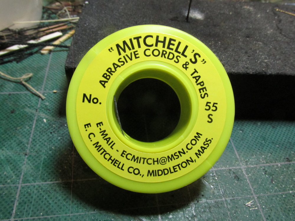
These deadeyes are now complete. I had to increase the teeth depth on my “knife” which I now understand is technically called a broach and was held by a hand pin vise. I also had to introduce the use of an abrasive cord. The cord was immeasurable useful in its ability to help increase the width of the slots.


- 974 replies
-
- 1
-
-
- rattlesnake
- mamoli
- (and 1 more)
-
I made a similar mistake with the Mizzen mast as well and had to enlarge the top hole. Luckily the mast wedge that I had made covered just about all of the excess hole that was left when the mast was finally seated. Those tops really gave me all kinds of trouble. Yours look quite nice. The ships boat that came with the Mamoli kit was a pre-cut wooden shell and would have worked quite well and appeared to be a lot easier to use than MS's bread & butter version. Even still, I felt like it was cheating to use it since I had made most of the model from scratch once the keel and bulkheads were used. When I found the ship's boat model on Model Expo for $5 I had nothing to lose but try. Bending the ribs is the hardest part as the wood will kink rather then bend. If I could have figured out a way to draw the ribs to make a template, I believe it might have been easier to cut them out of airplane plywood. Sometimes I feel like I should have gotten a commission from Model Expo for the number of sales I inspired. 8-) Jonathan
-
Martin - Thanks for the warning on loose straps, I'll keep that in mind. Ah yes, the souvenir. There was/is no chance of radioactivity because when I obtained the bar of stainless steel, the power plant was under construction - no nuclear fuel was on site. For those of you who didn't click on the provided Shoreham link, the plant was finally completed and even got up to 5% power for testing but was never commissioned. This was around the time of the 3 Mile Island incident so a lot of people (politicians, anti-nukes, pro-nukes, etc.) took a second and third look at the emergency plans if the plant went operational. They didn't like the evacuation plan. Trying to evacuate the population from Long Island NY is messy at best on a good day, never mind during an emergency. So the fully functional, brand new nuclear power plant never went on line.
- 974 replies
-
- 1
-
-
- rattlesnake
- mamoli
- (and 1 more)
-
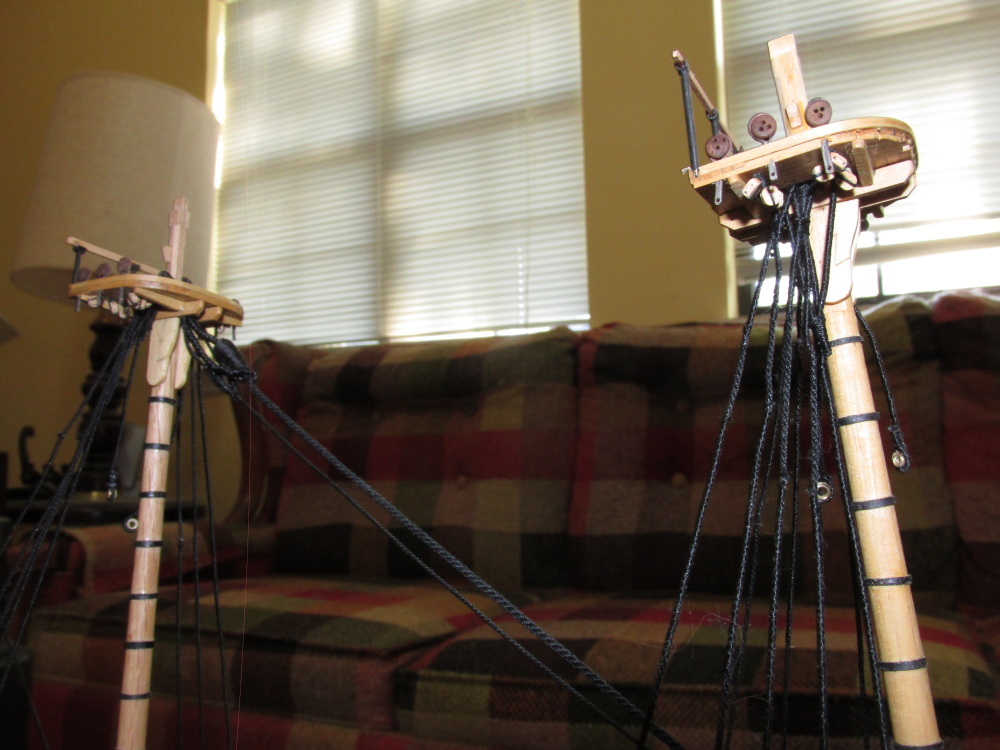
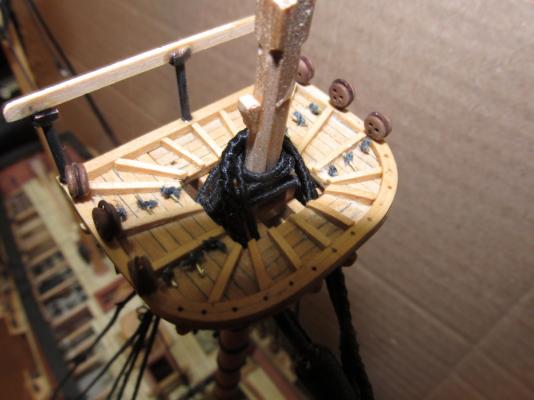
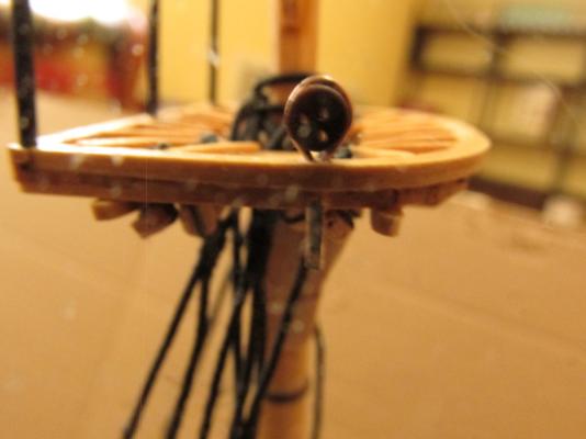
Once the “saw” was able to pass through the opening I tested the deadeye again. Success, it fitted! Now I have to do it again 17 more times only this time, I don’t think it will go as quickly as their fabrication. The pictures below show the small deadeye slots as well as the one deadeye that I was able to insert into the top so far.

- 974 replies
-
- 3
-
-
- rattlesnake
- mamoli
- (and 1 more)
-
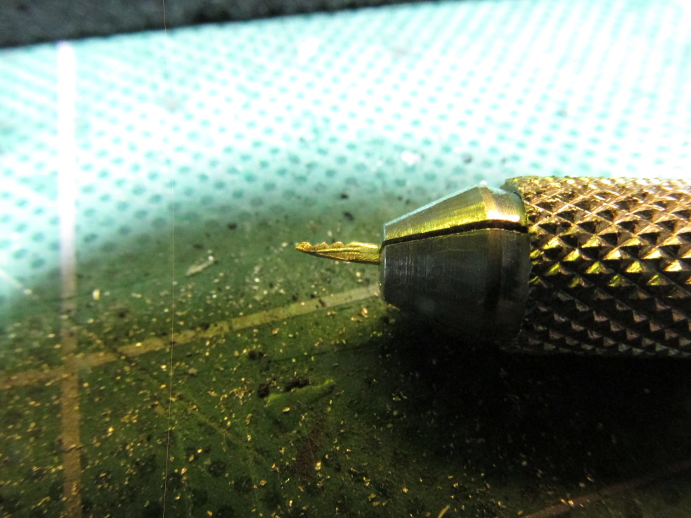
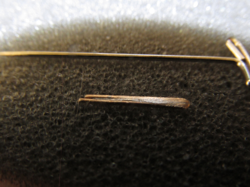
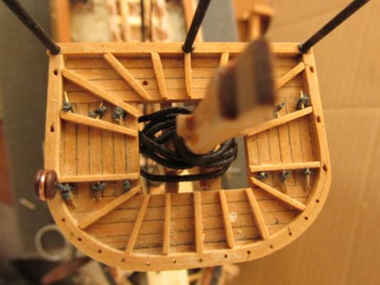
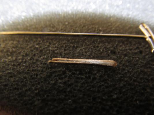
Before I decided to blacken the straps, I test fitted them to the tops. They didn’t fit into the fine holes I created for them. I was too conservative and made the openings a bit too small. The stems of the straps are about 0.5 mm x 2.0 mm. The strap openings are about 0.5 mm (max) X 1.75 mm (or less). Obviously it would be very simple to fix the openings if the tops were off the model but I can’t remove the tops without disassembling all the rigging I’ve done so far. I don’t have a knife or other tool that can be used widen the width of these very tiny strap slots. So I’ve attempted to make one. Using the excess tail of a completed strap, I’ve filed it down to the proper dimensions and then tapered one end so it could at least fit part way into the hole. In addition I filed some notches on one side to act as saw teeth which you can barely see in the image below. This is a fragile copper and silver solder tool (to be held with a pair of pliers) bends quite easy if not held just right. Using a hand drill to act as a rudimentary file, I moved the drill up and down against one end of the strap slot. This slowly made the hole longer. Using my homemade “saw” ensured the cut was straight.
- 974 replies
-
- 3
-
-
- rattlesnake
- mamoli
- (and 1 more)
-
Well, I’ve completed all 18 deadeye straps except for the blackening process. Once I got into the routine, I reduced the time to create one from a half hour to ten minutes or less and they got better. Practice makes perfect. But there is a problem.
- 974 replies
-
- 2
-
-
- rattlesnake
- mamoli
- (and 1 more)