Louie da fly
-
Posts
7,990 -
Joined
-
Last visited
Content Type
Profiles
Forums
Gallery
Events
Everything posted by Louie da fly
-
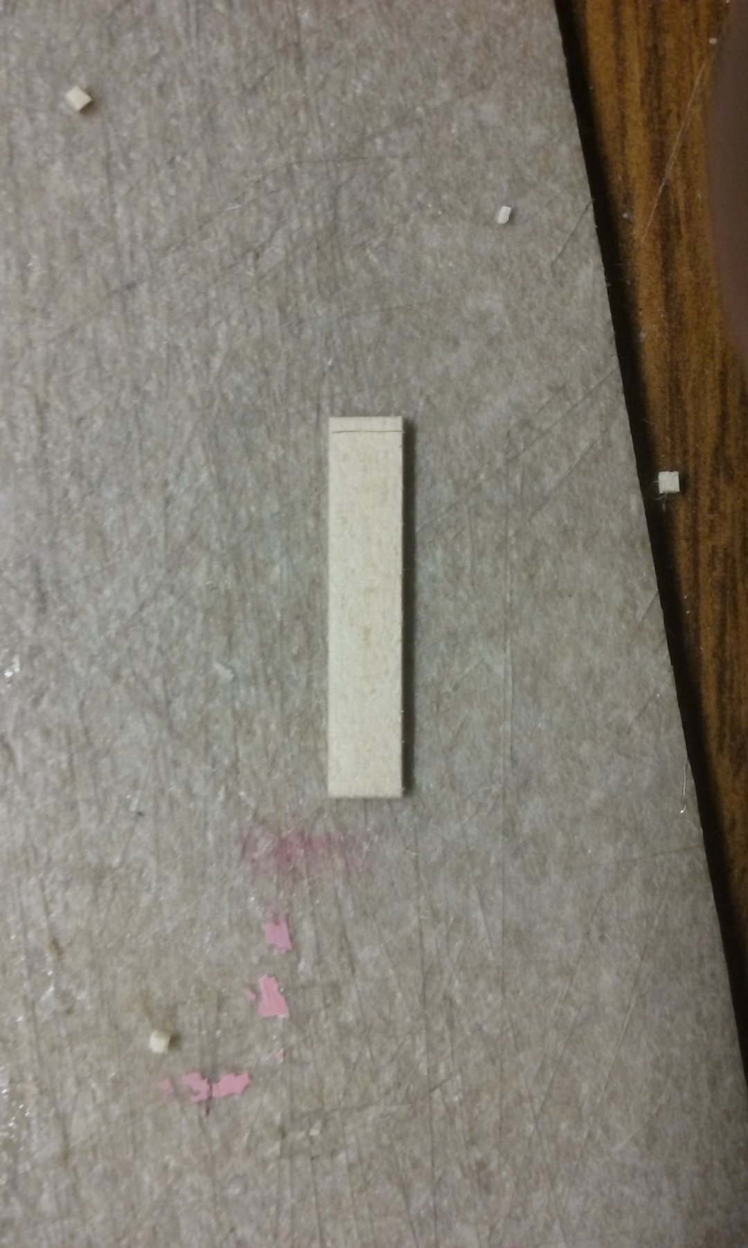
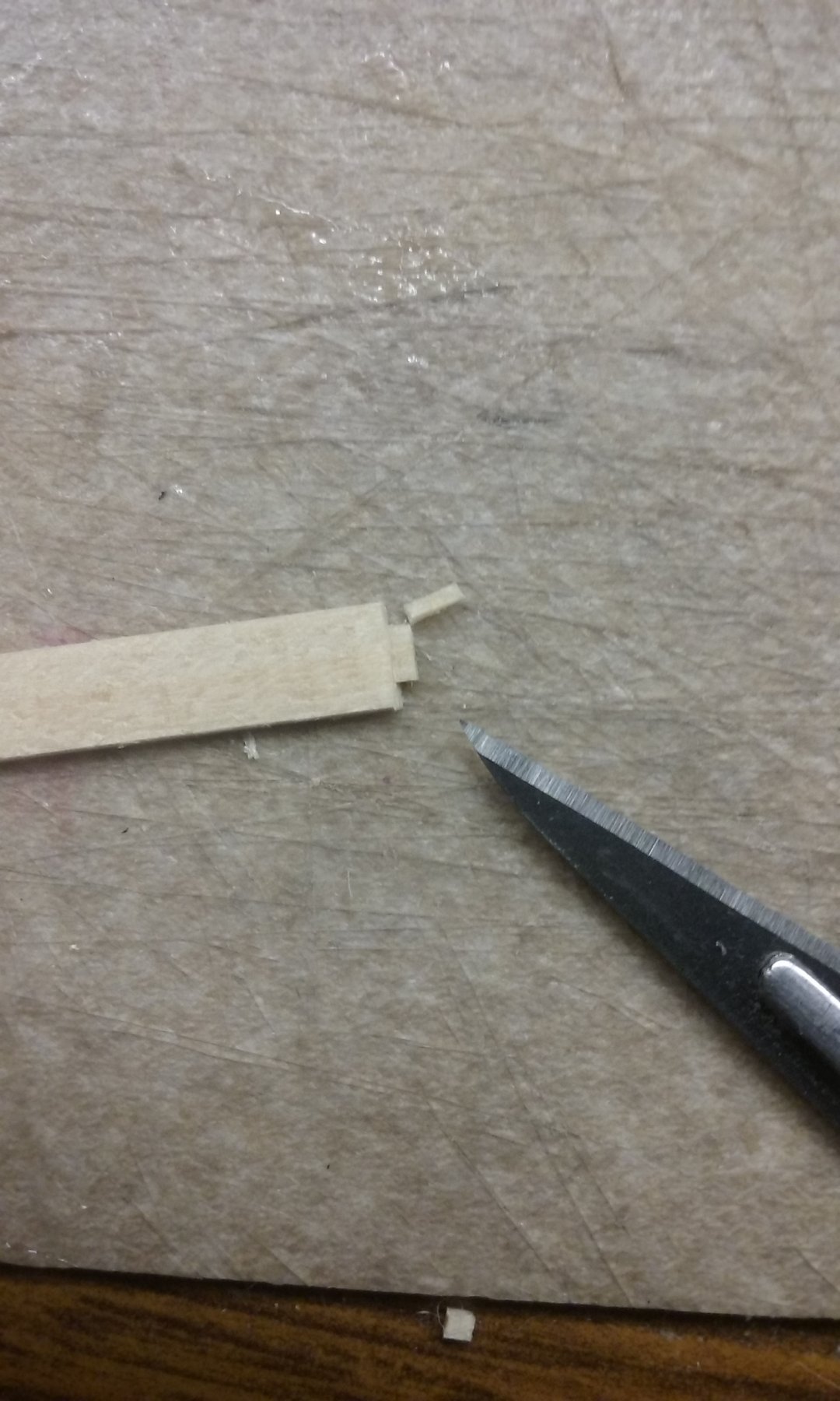
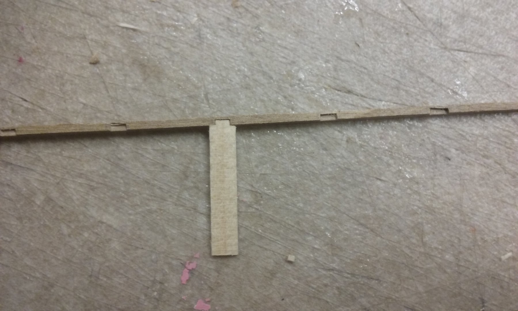
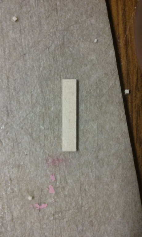
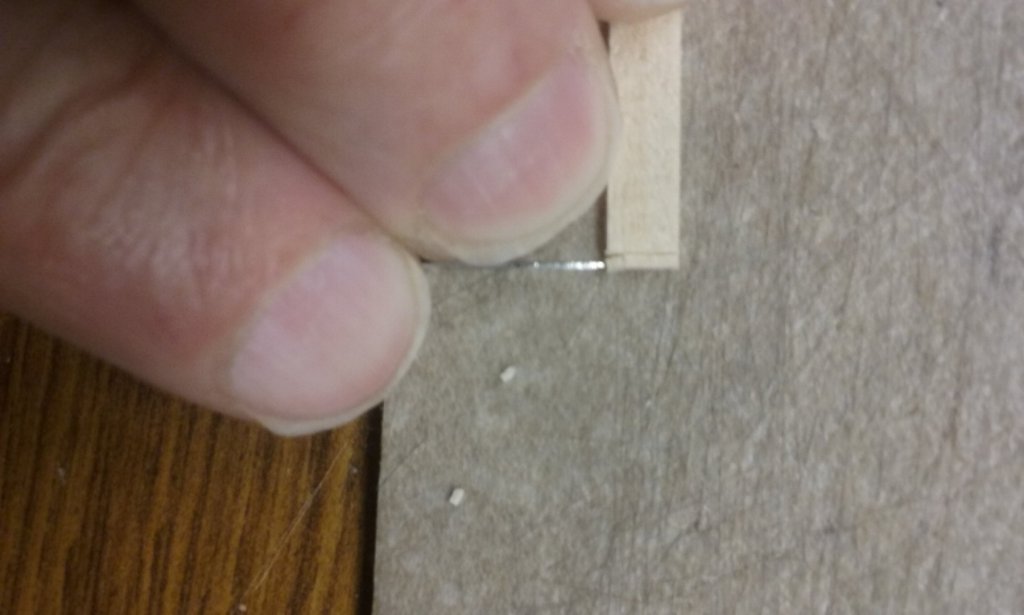
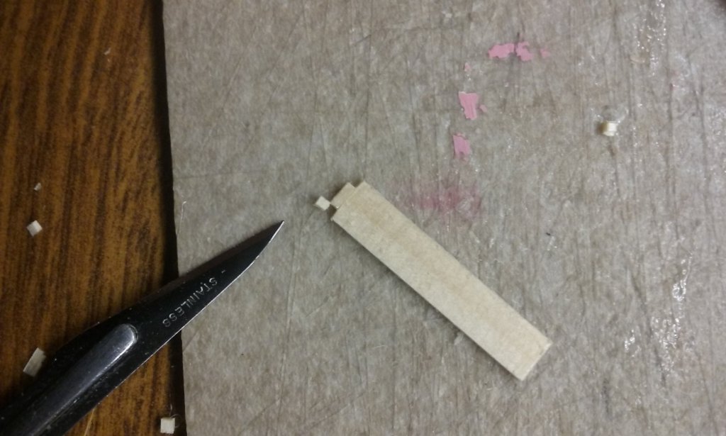
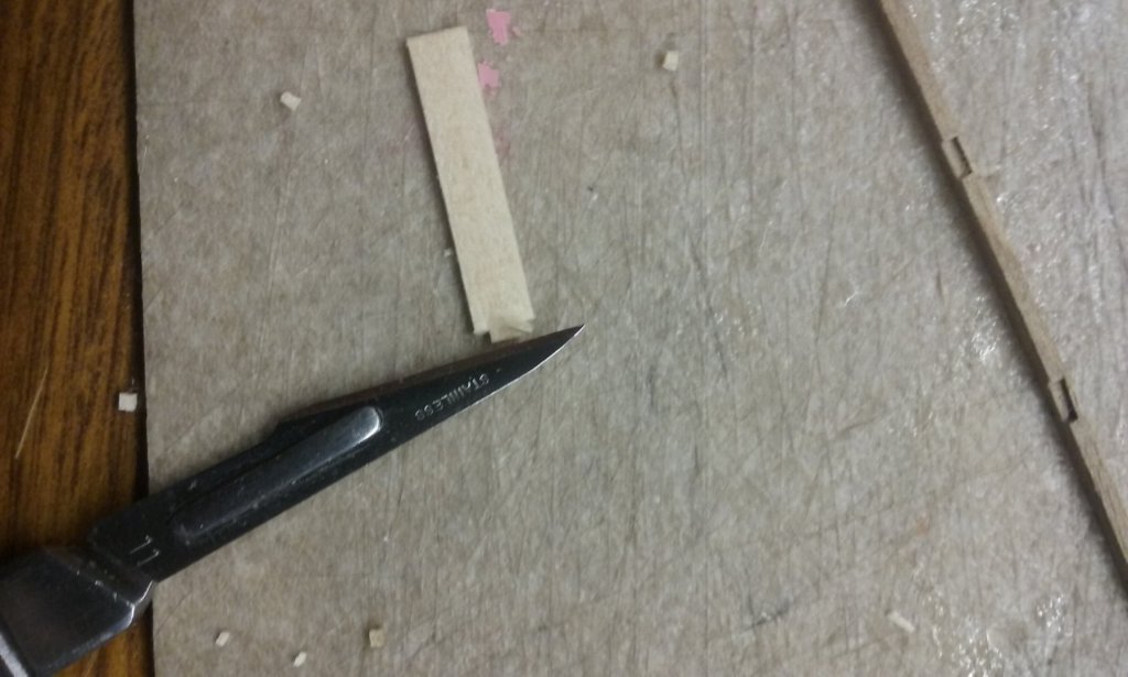
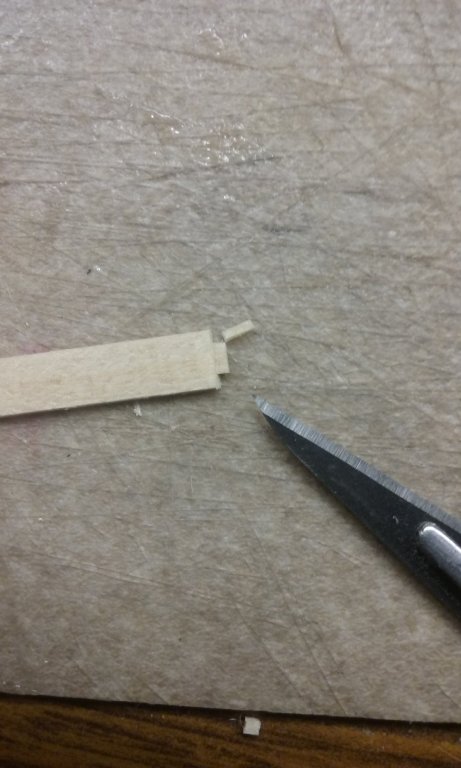
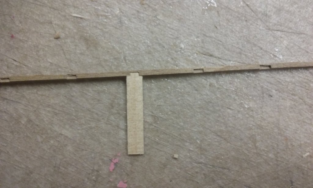
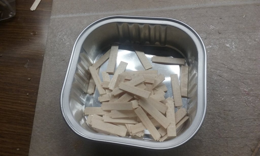
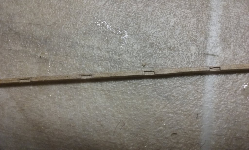
 Here's the starboard stringer with the slots carved out of it. And the forward end glued in place. And the stringer curved and glued in place bit by bit: Here are the upper oarbenches under way: The blank, with a line cut into the end for the beginning of the tenon: Cutting the tenon to shape: And thinning the tenon to fit in the slot: Fifty benches: Scarph joint for the second half of the stringer: More to come . . . Steven
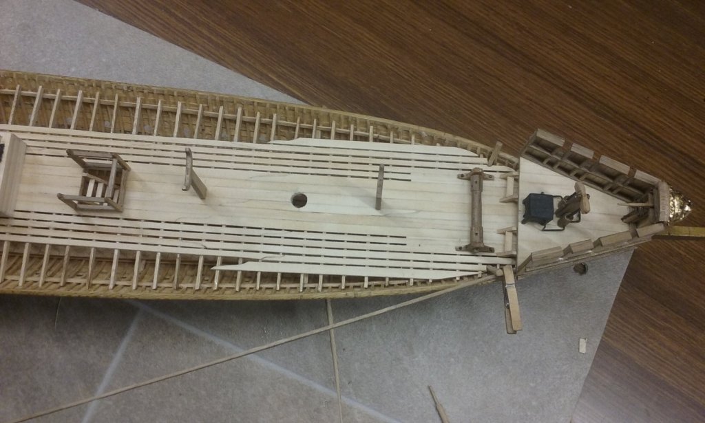


-
Oh, I was prepared to cut the slots in the gunwale, but I have to admit doing it this way will be easier.☺️ Steven
-
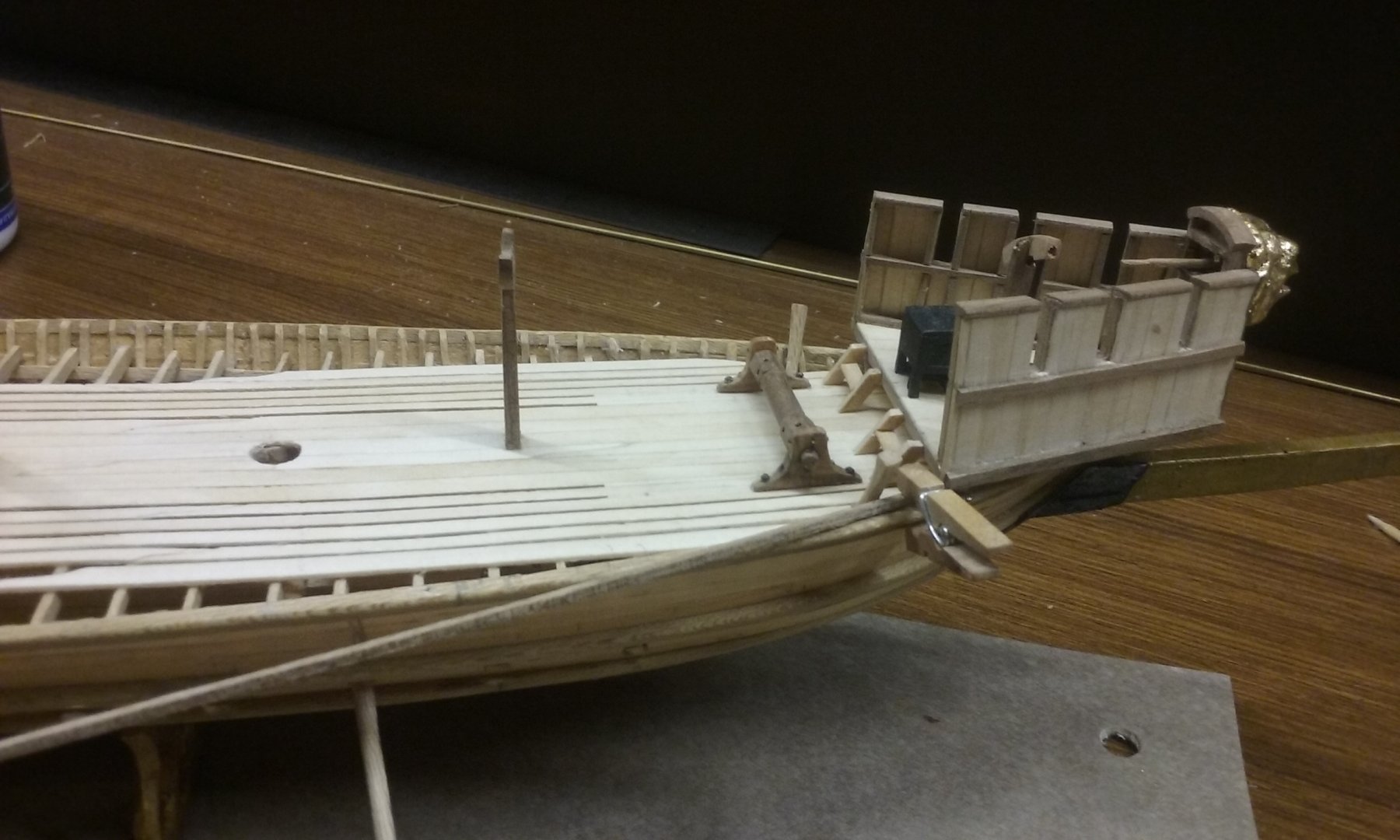
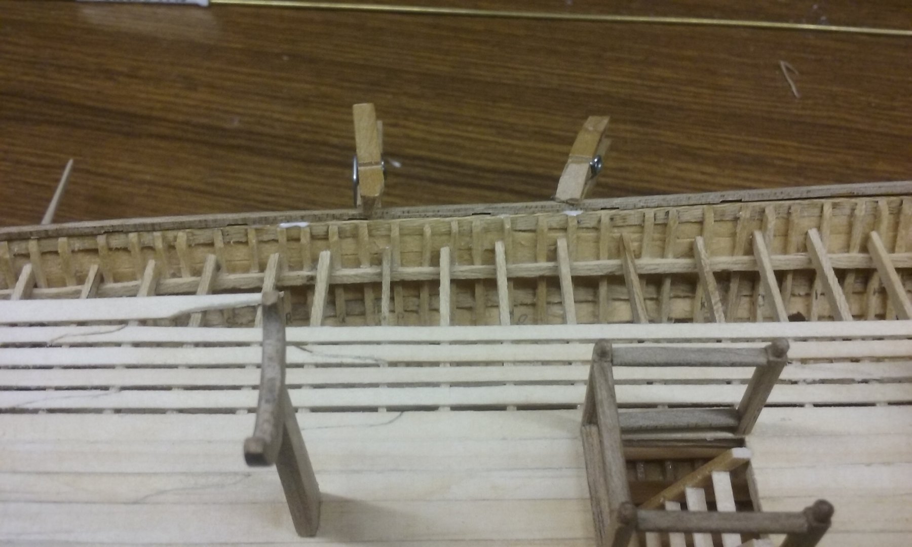
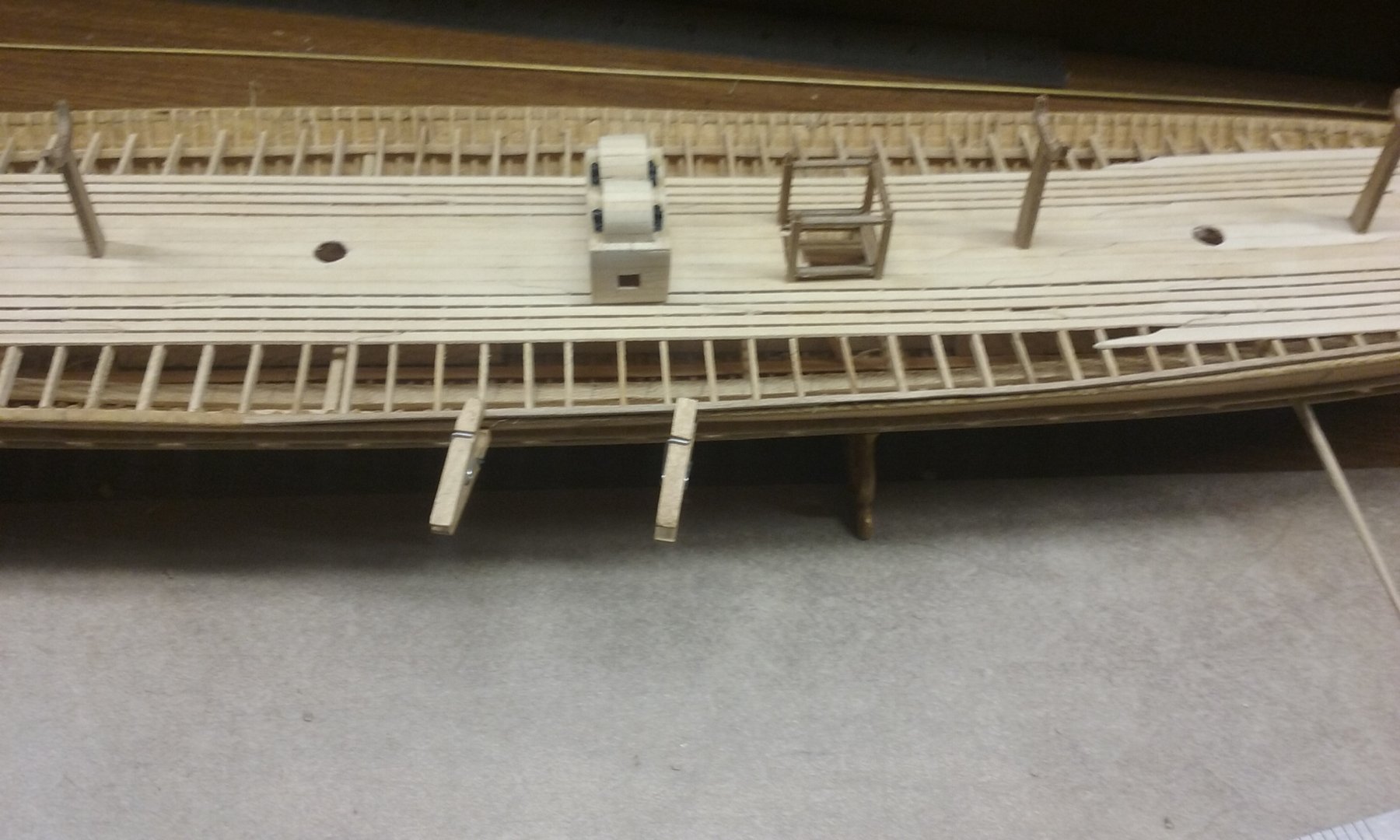
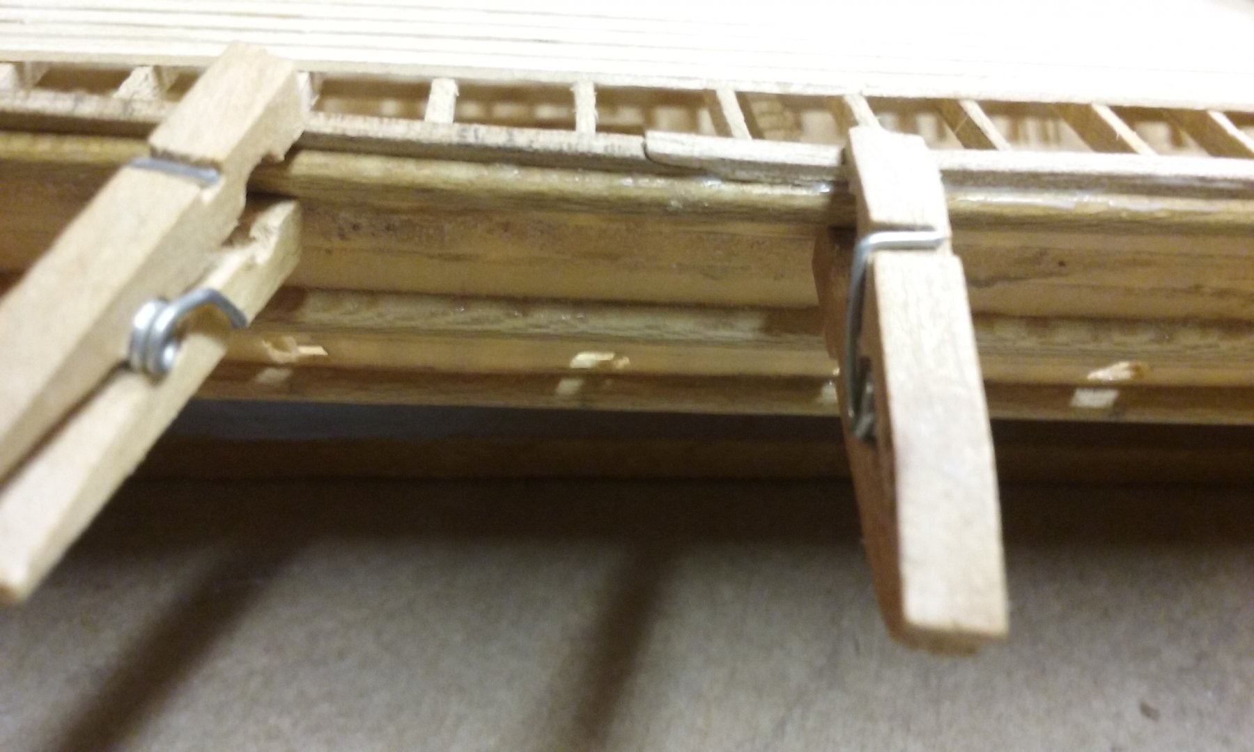
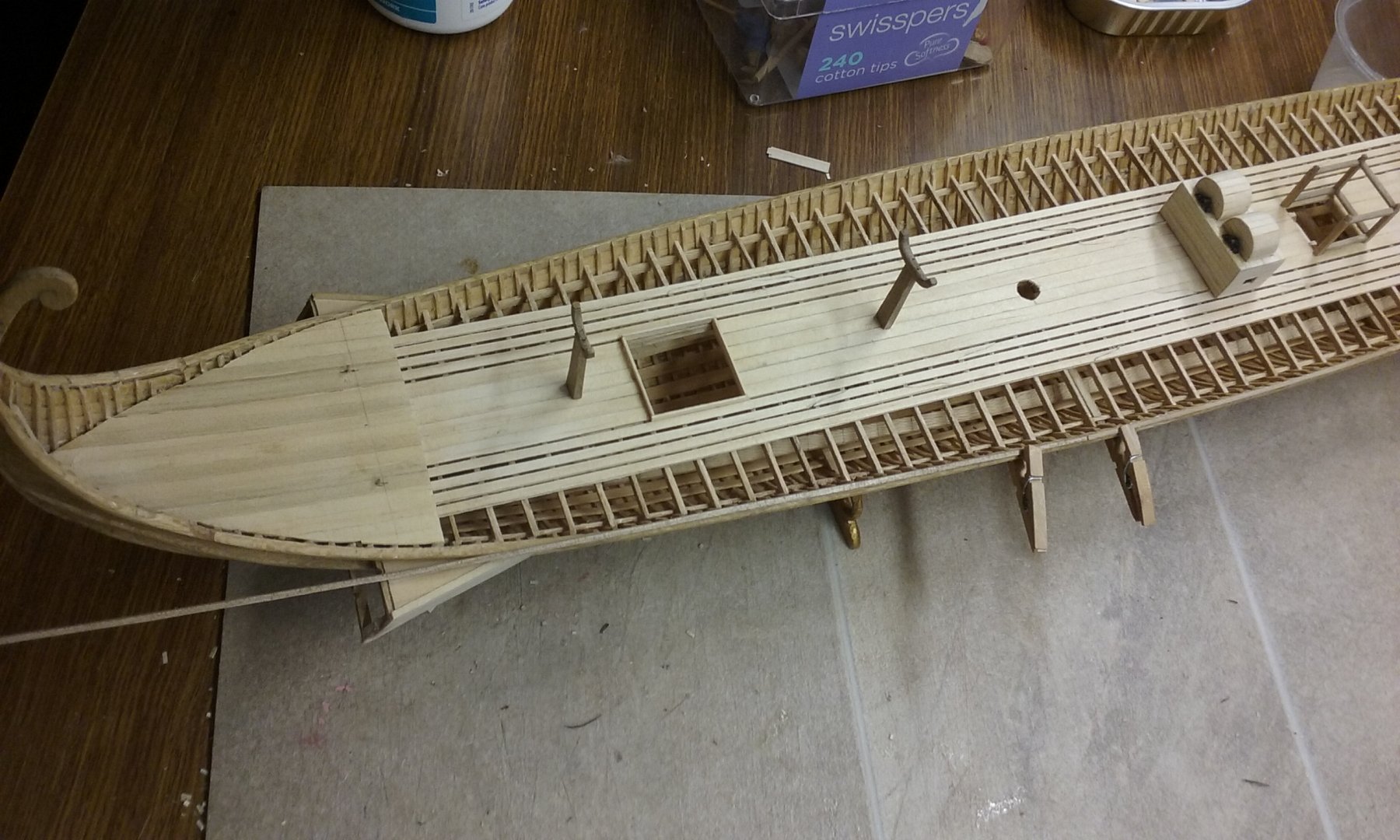
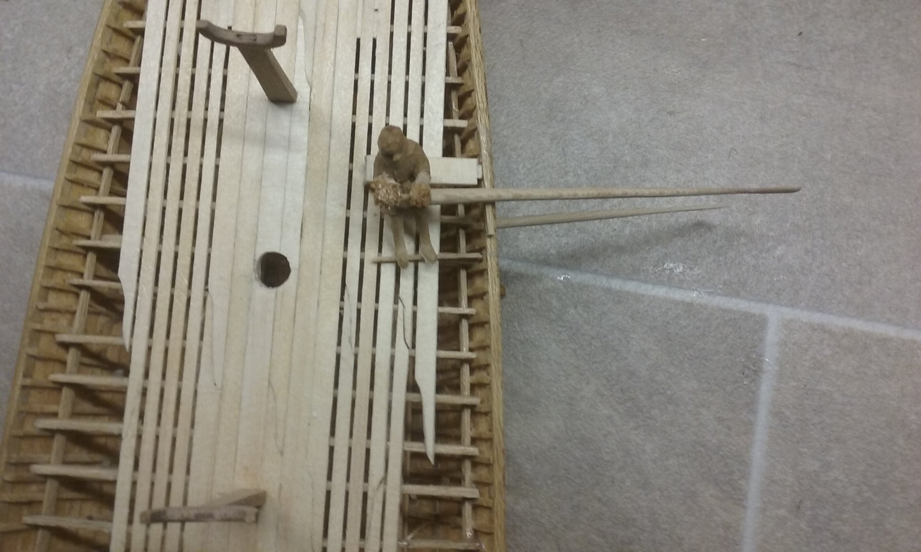
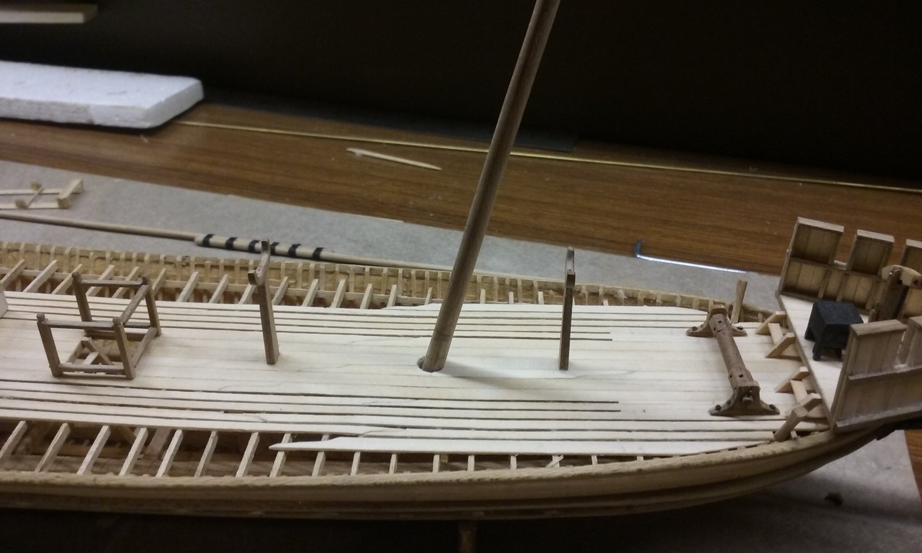
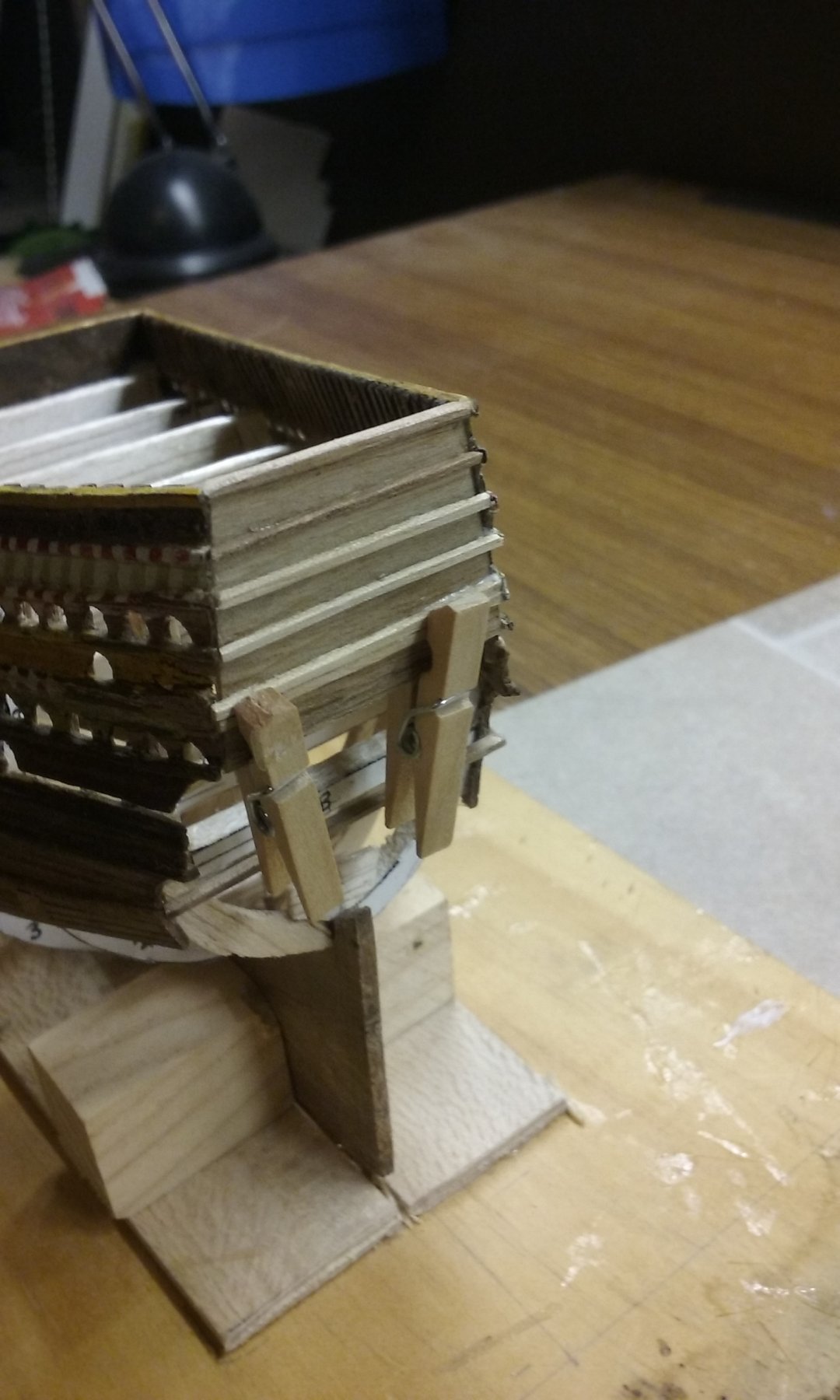
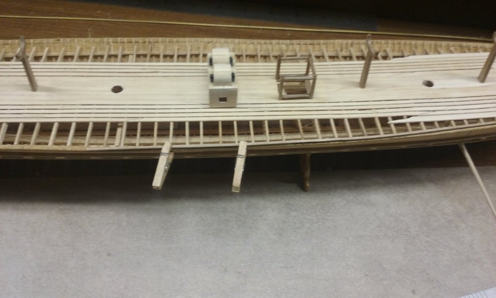
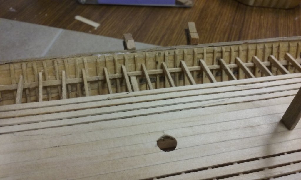
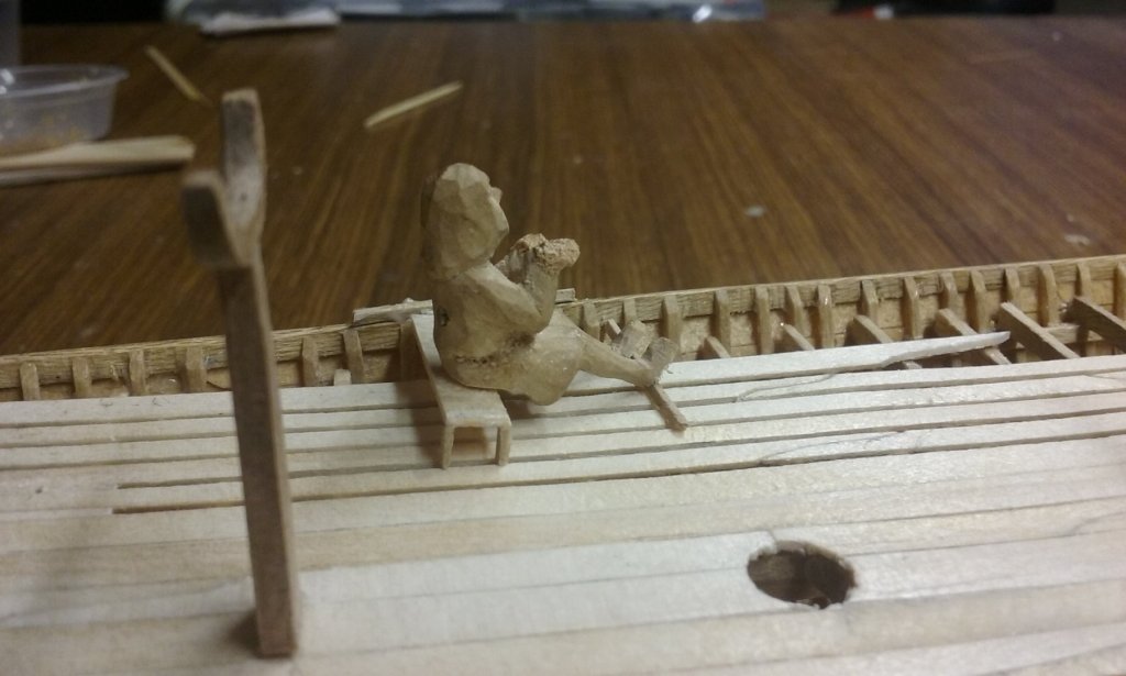
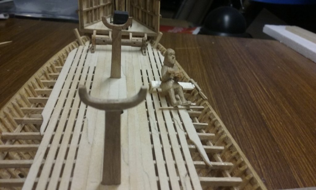
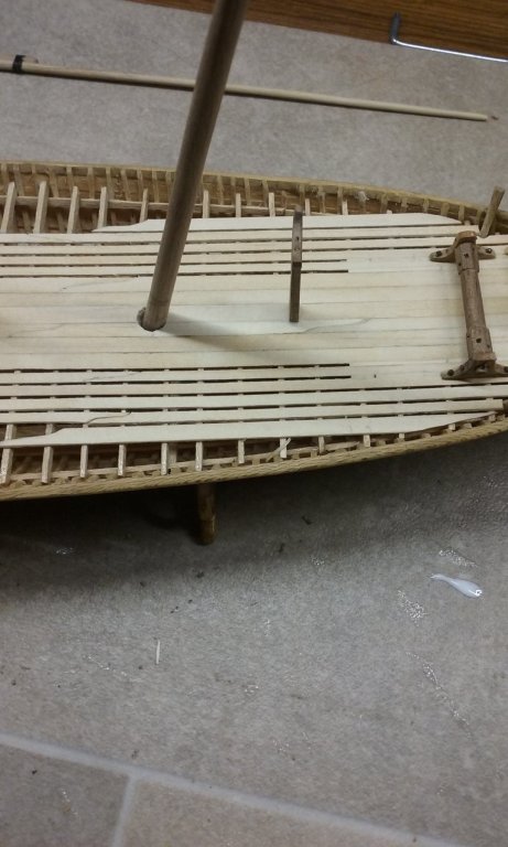
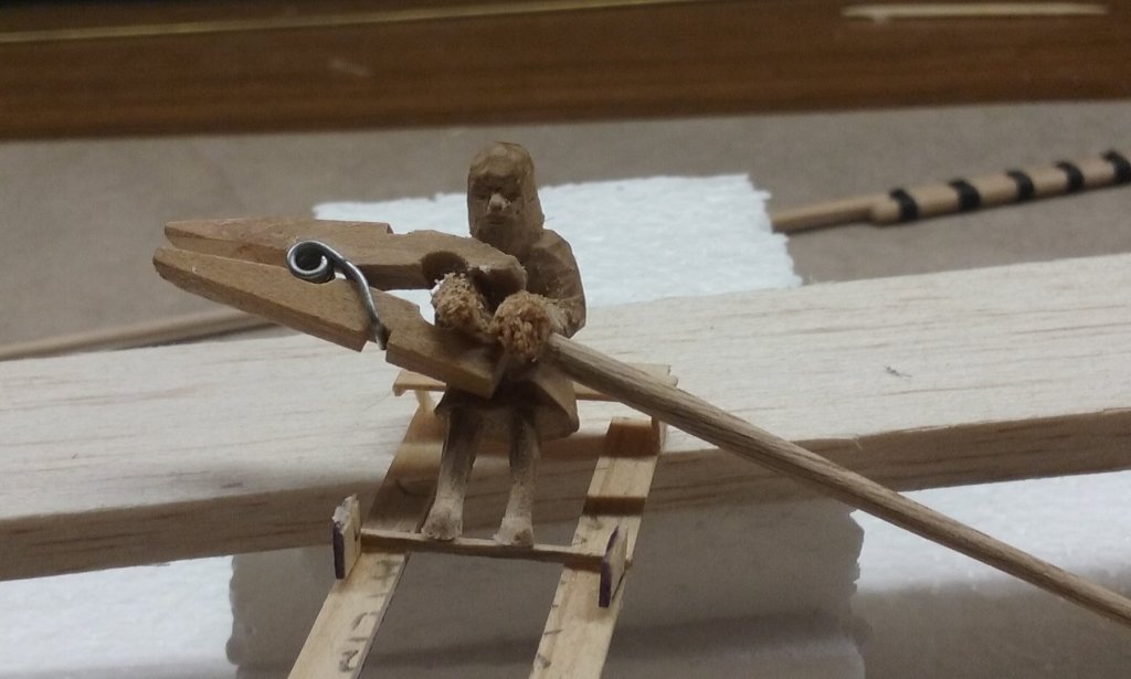
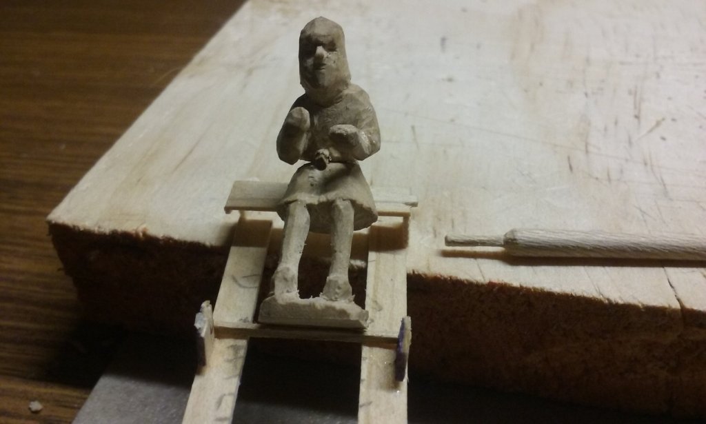
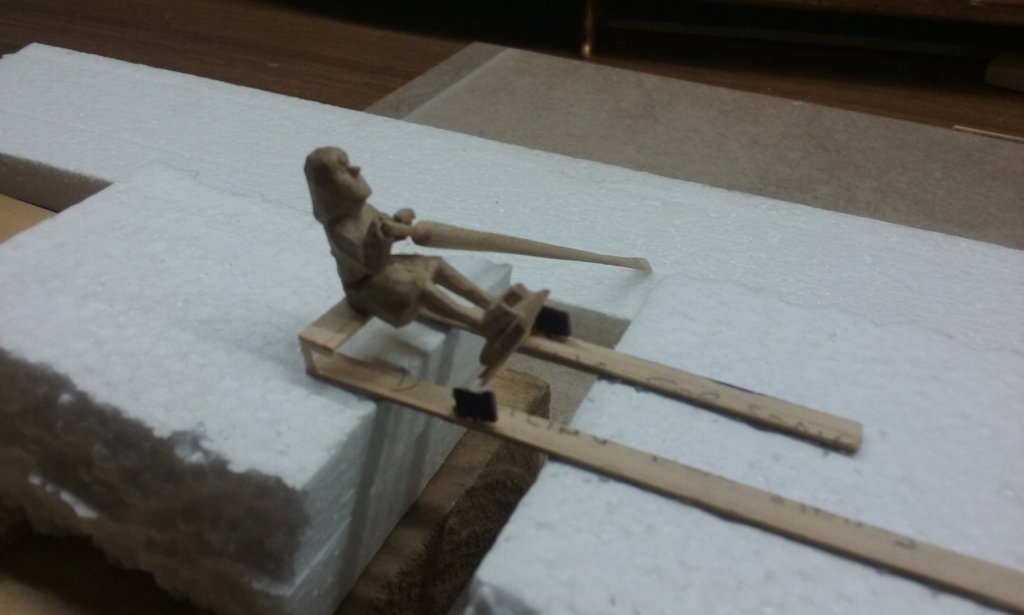
Thanks everyone for the likes, and thanks for the comment, Pat. I've worked out how to solve the problem of the gunwale being slightly too low for the bench to be slotted into it - currently with everything at the right height the bench rests on top of the gunwale. So I've decided to put in another, thinner, stringer (I suppose that's the right name) on top of the wale, and I'll be carving slots into the bottom of this stringer, with the top of the gunwale forming the bottom of each slot. I've temporarily added a couple of bits of wood at the top of the gunwale to test this out and it all seems to work ok - you can see them next to the oarsman. I've cut the stringers and I'll add them shortly. I've also been working on the relationship between the lower and upper banks of oars. By rights, at any moment both upper and lower oar blades should be at the same level horizontally (so they're both be in the water at the same time) and the same angle in relation to the axis of the ship (so they don't foul each other). I've pretty much set up the level of the lower oar-blades by putting in a frame below decks to glue them to, so as a preliminary I've glued in my first lower oar. And I've set the lower oar's angle to the axis to follow that of the upper oars (which is mostly determined by the position of the upper oarsman's hands). Now we get into the fine adjustment; until now I couldn't predict where the upper oar blades would end up in relation to the lower ones. it turns out the angle of the "test" upper oar is too shallow, so its blade has ended up higher than that of the lower oar. As the levels of the thole and the oarsman's outboard hand are pretty much set, the only way to alter the angle is to raise his inboard hand. So - more filler to build it up higher, and I'll carve it to shape later. I had originally intended to insert the lower oars blade-first from inboard, which is why I left a bunch of planks off the deck. But with all the other stuff up there now, it looks like it will be better to insert them handle-first from outside. So I've had to carve the handle-ends so they'll go through the oarports - 50 of them. Just finished doing that. So I'll soon be putting the lower oars in and gluing them into place. It's been a long time coming, but if I'd put them in earlier there's have been too much chance of accidentally breaking them off as I worked with the other stuff. When I put the upper oarsman in place it was only a temporary measure to work out the angles and heights. I placed him at random without reference to the lower oarports, so I'm going to have to take off again. But that's a fairly minor issue - I still have to make 50 oarbenches, cast 50 oarsmen, put the all benches in position 12.6mm forward of the lower tholes etc etc Steven


-
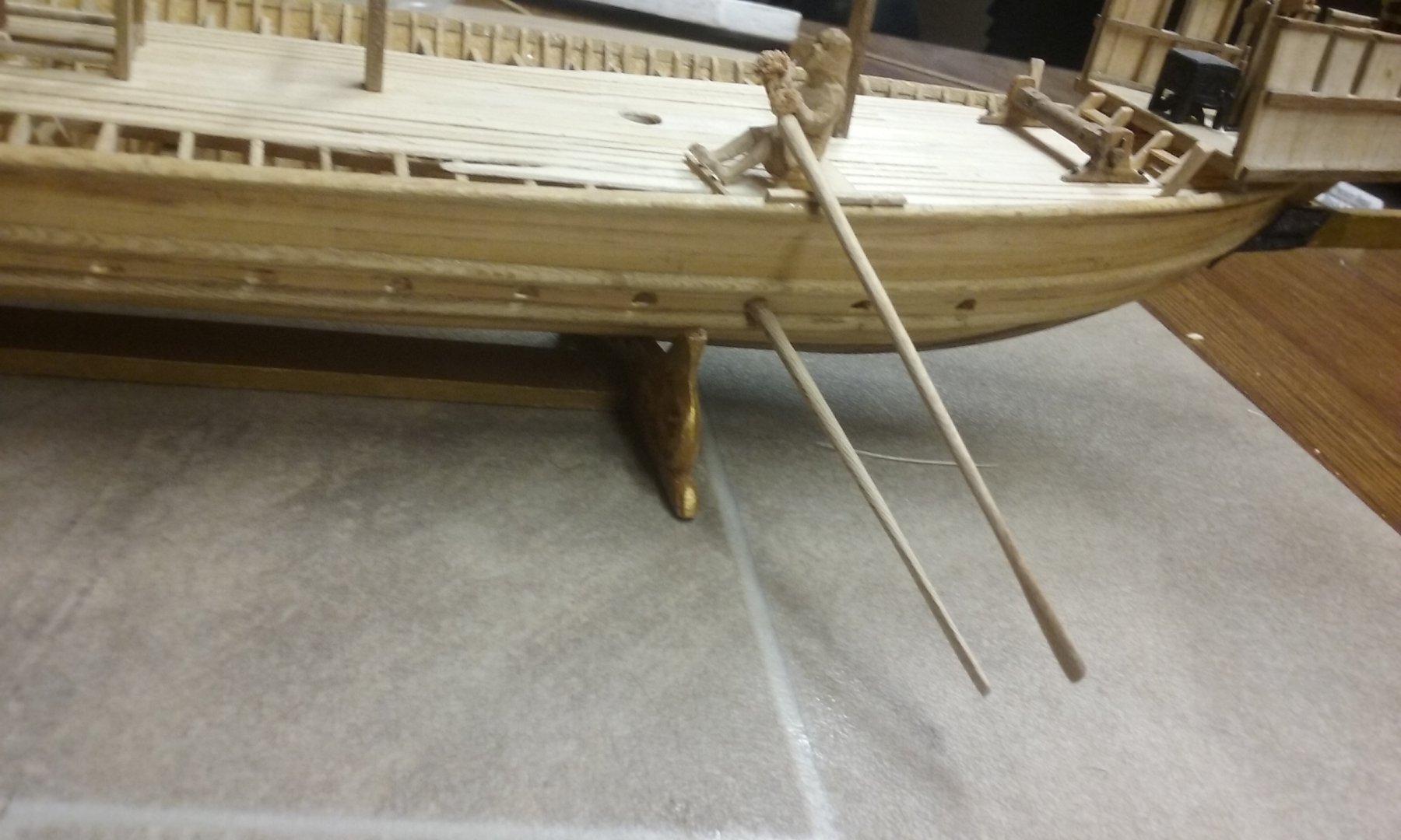
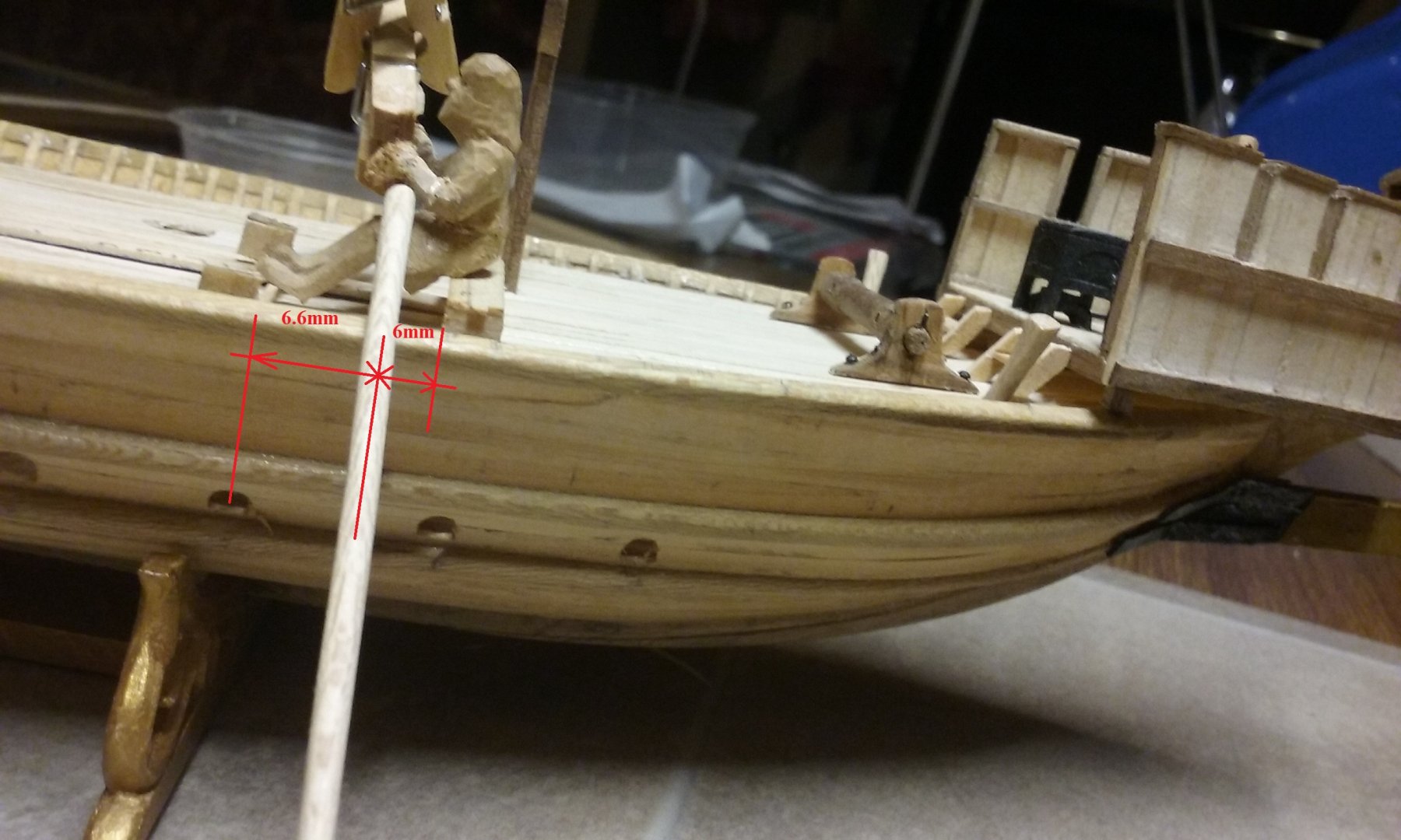
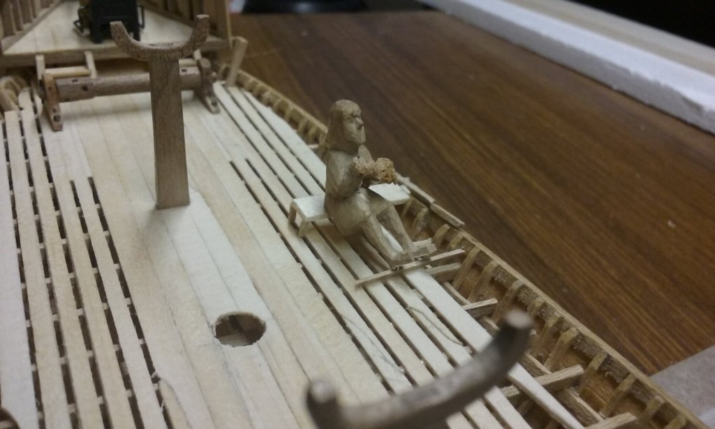
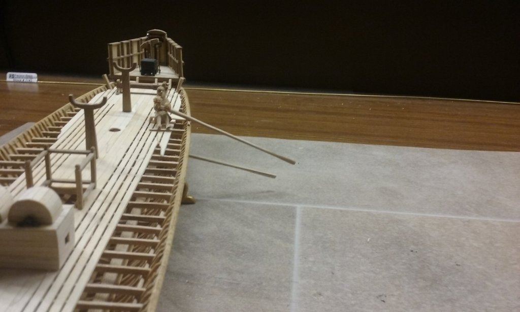
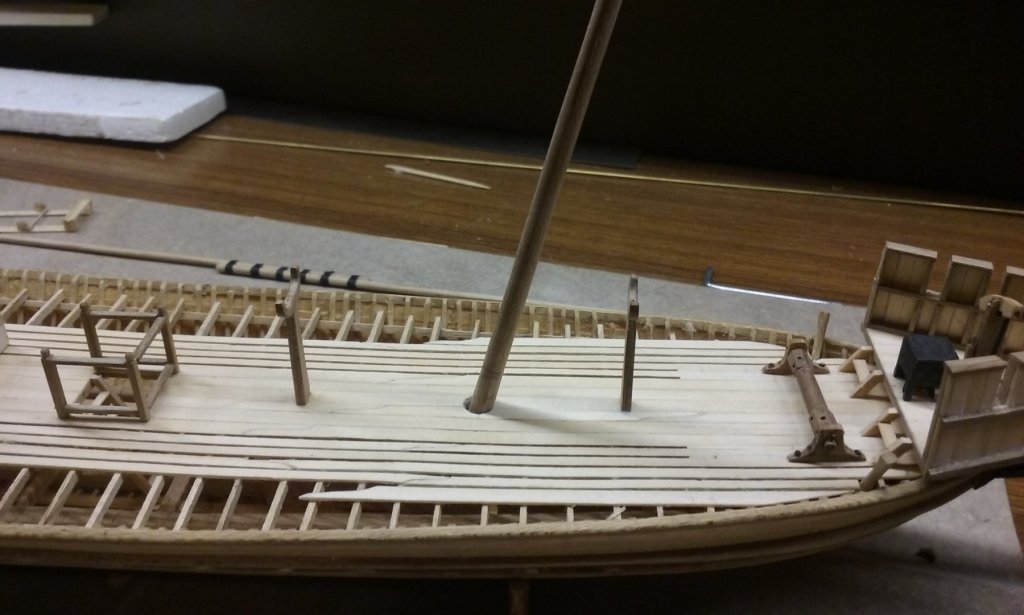
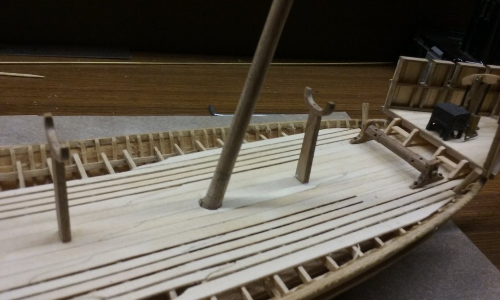
Thanks for the likes and comments. Carl, there's an old story (Ancient Greek?) about captives having their thumbs cut off so they couldn't hold a weapon but could still be made to pull an oar . Not sure if there's any truth in it . . . I'm working on exactly where to put the upper oarbenches. Pryor's book Age of the Dromon specifies that to avoid fouling between the two banks of oars, the upper oars should be 330mm forward of the lower ones. This translates to 6.6mm at 1:50 scale. But then you have to allow for the horizontal distance between the thole (the oar-pivot at the gunwale) and the front of the oarbench, which is a fairly complicated thing in itself. The thole has to be located in the best position relative to the oarsman to make it comfortable and mechanically efficient to use the oar. I've looked at a fair bit of information on the theory of all this and it's all a bit confusing - and complicated by the fact that modern oared vessels (racing shells) have sliding seats. Looking at vessels with non-sliding seats (whalers, and of course Olympias), there seems to be a fair bit of variation as to what is believed to be the best position. In the long run I decided to approximate as best I could the distances on Olympias, adjusted in accordance with the little guy I've made (also based on Olympias). Based on that, I put the guy on the deck and measured the distance between the thole and the front of the bench. It comes to about 6mm. So, adding that to the 6.6mm specified by Pryor, each upper bench should be 12.6mm forrard of the corresponding lower thole. This has been bugging me for a long time, and it's nice to have sorted it out. The eagle-eyed among you may notice that I'll have to lose the forwardmost upper bench. I'll probably also lose the aftmost one, because the steering oar gets in the way. Part of the learning process. If I did it again, I'd be making the ship longer to take these problems into account. In the original Byzantine galaea found in Istanbul, each bench had a tenon slotted into a mortise in the upper wale. However, it appears that the upper deck on this model might be too high for that and I may have to add another wale above the existing one to take the mortise. I'd been a bit concerned that I might have to do that, but this is also part of the learning process. Had I my time over again, I'd make the upper wale just that little bit higher - it would also have allowed both the forecastle and the poop to be higher as well, which I would have preferred. It would have made distance up to the poop to be more than a single step, and might have allowed me to put the Greek Fire apparatus below the forecastle as described in the contemporary sources. Steven

-
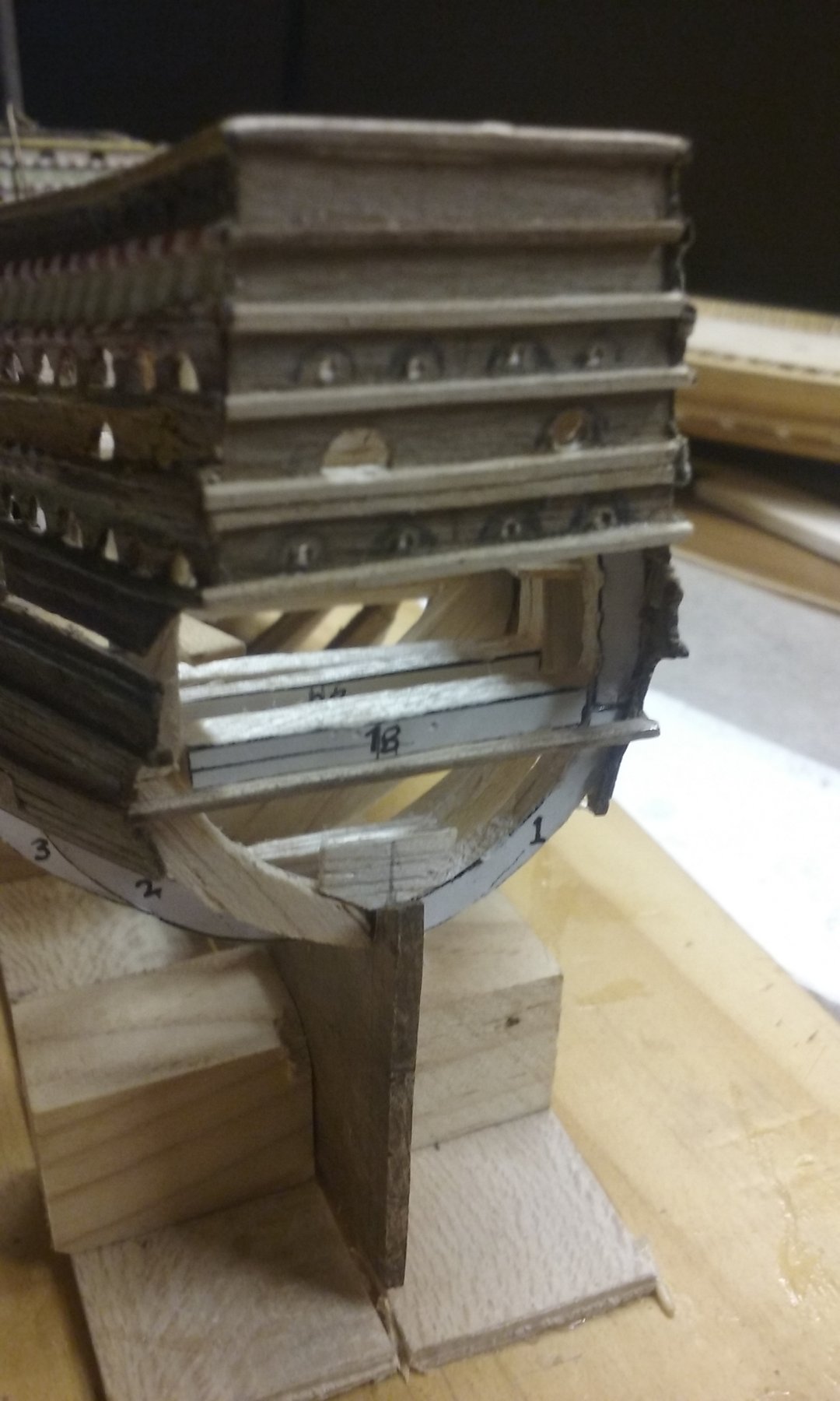
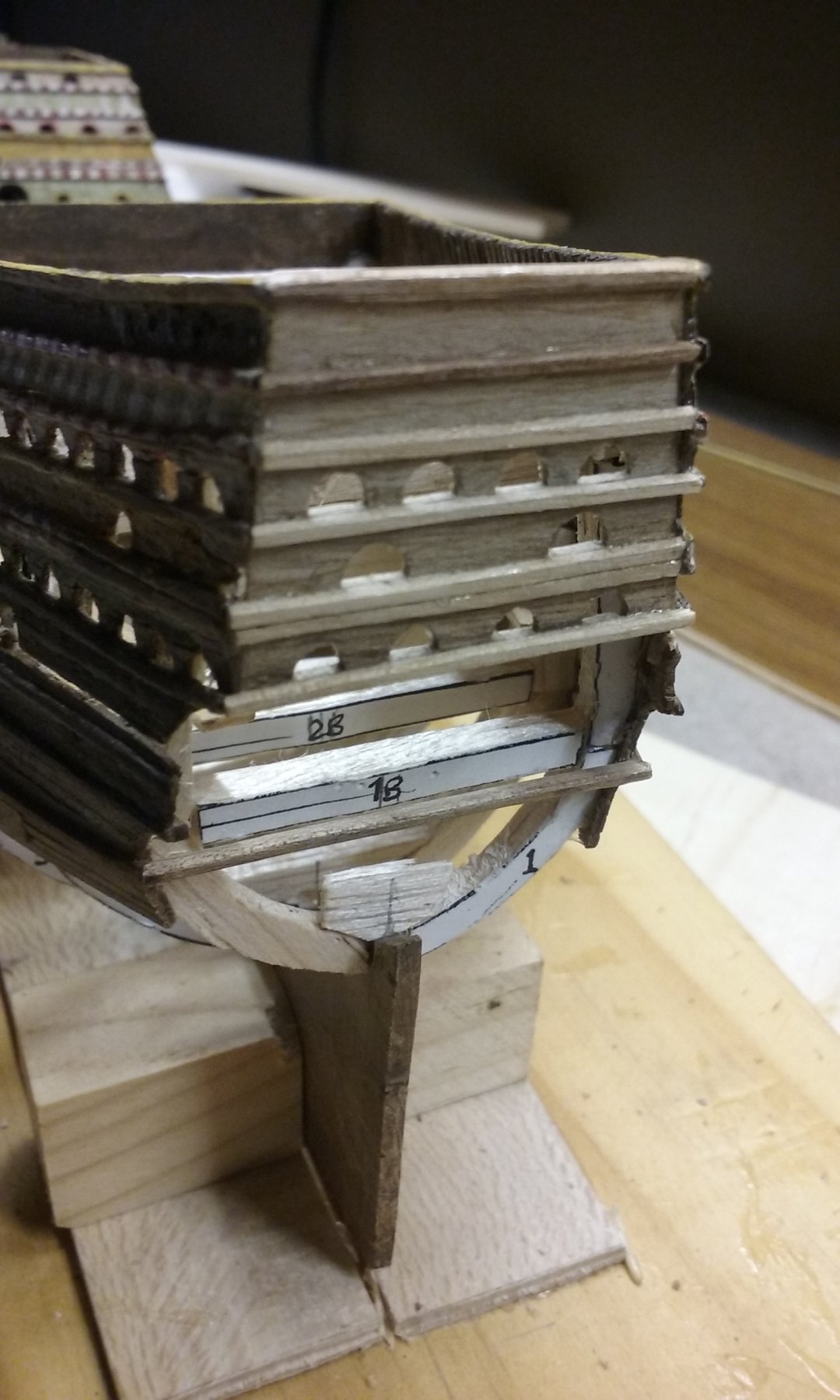
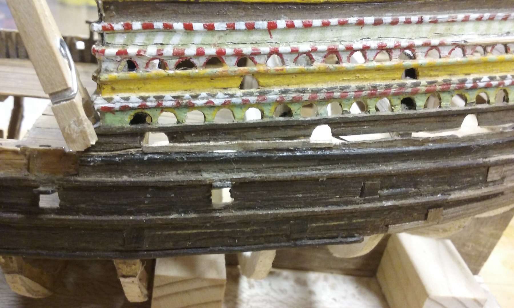
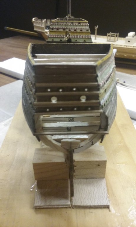
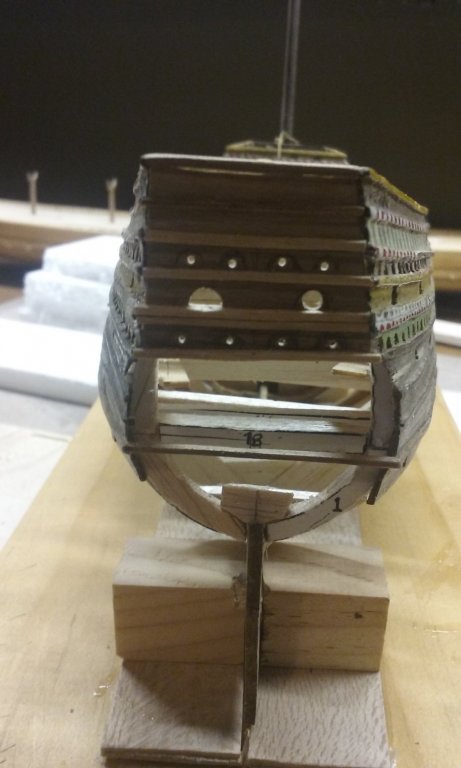
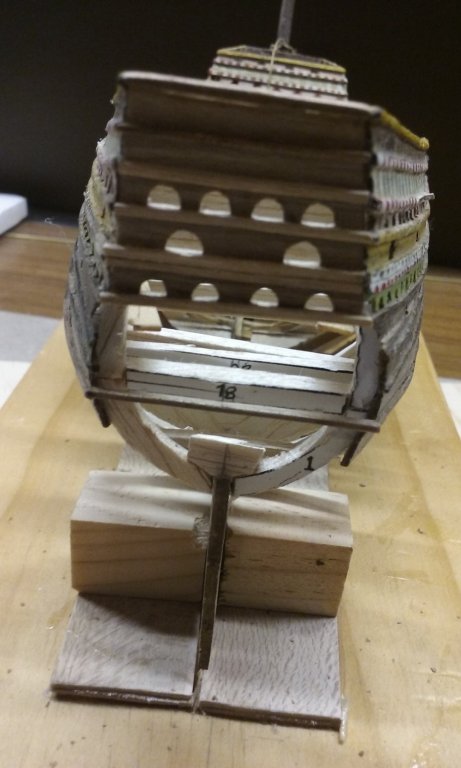
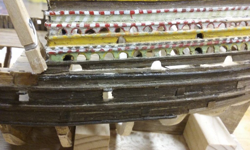
The arched holes in the transom have now been done. I started off drilling holes where they were to go: Then one by one cutting around the holes with a No. 11 scalpel to make them into arches of two different sizes - larger ones for cannon and smaller ones for railing pieces or swivel guns. All done. And I've started filling in the gap between the lower and upper works on the port side of the ship. The lighter colour wood is the new stuff. Steven


- 740 replies
-
- 8
-

-
- Tudor
- restoration
- (and 4 more)
-
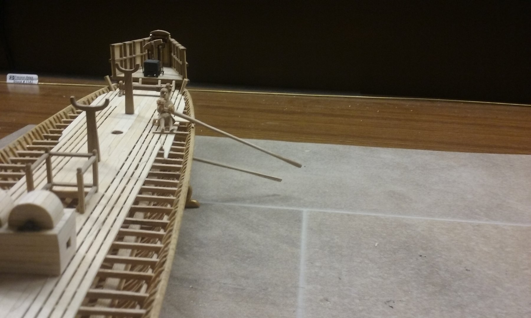
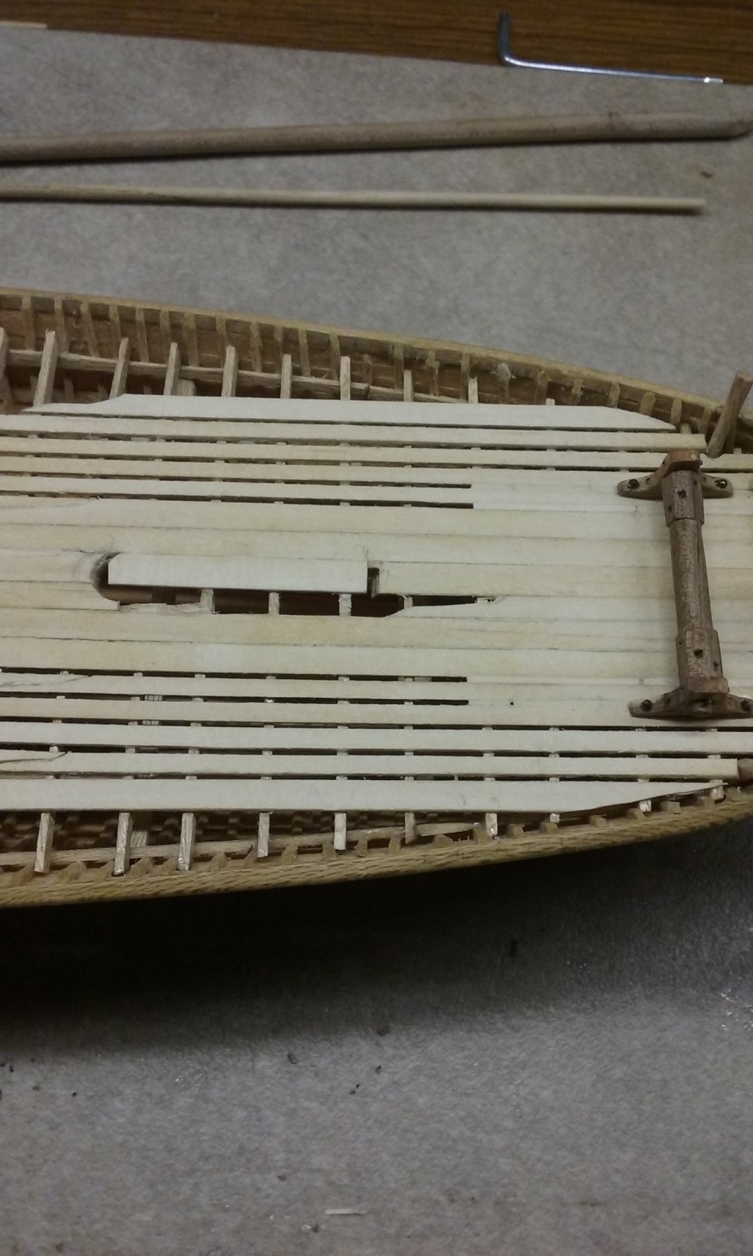
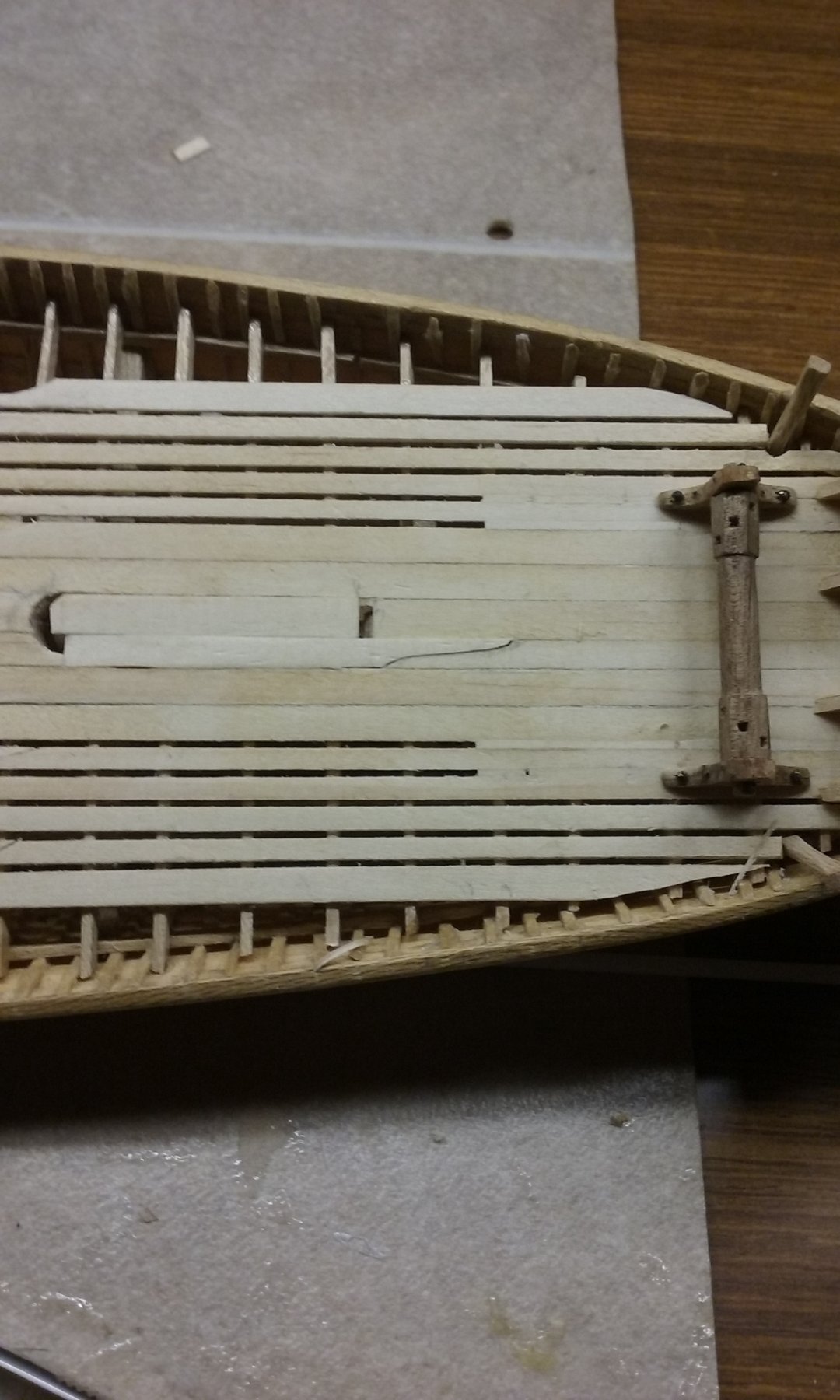
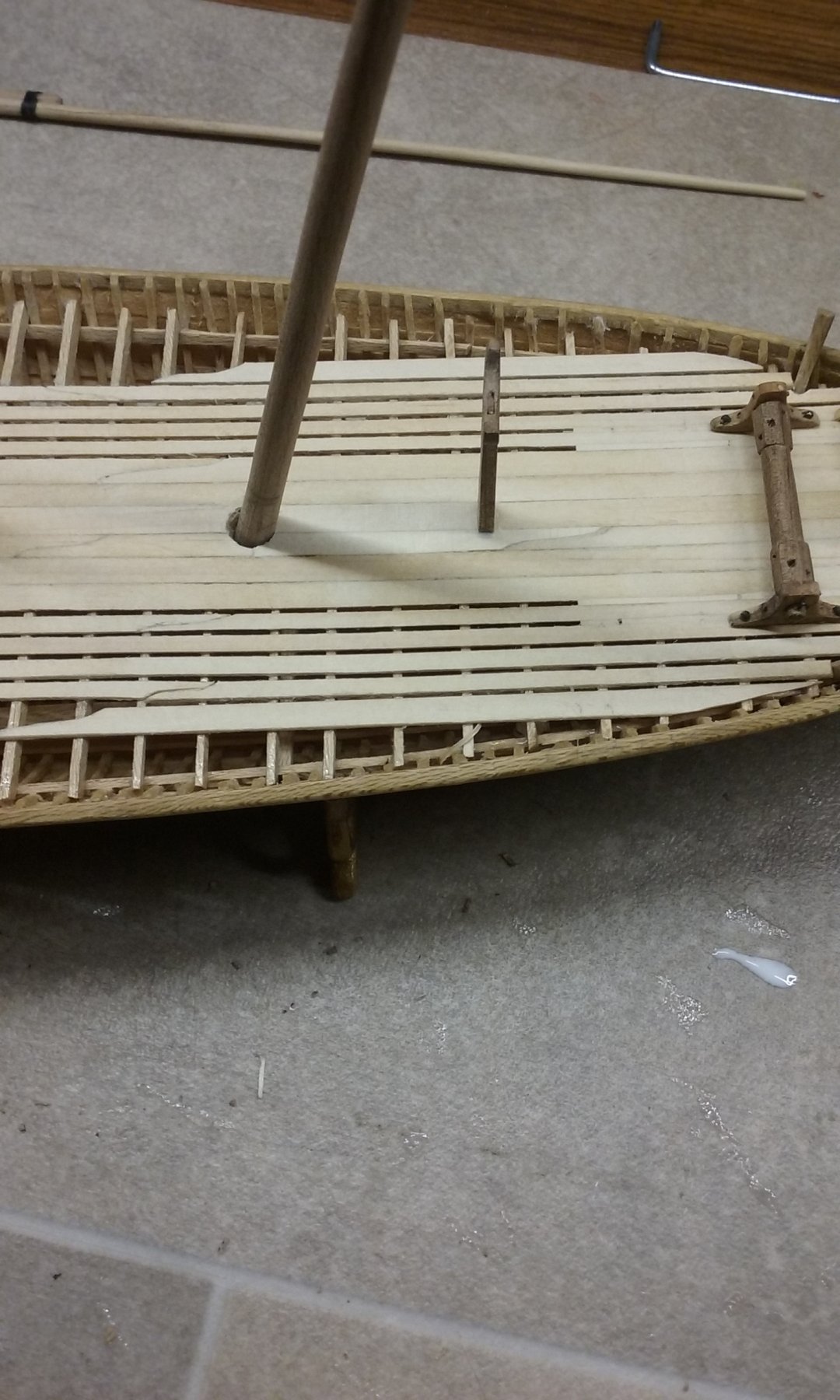
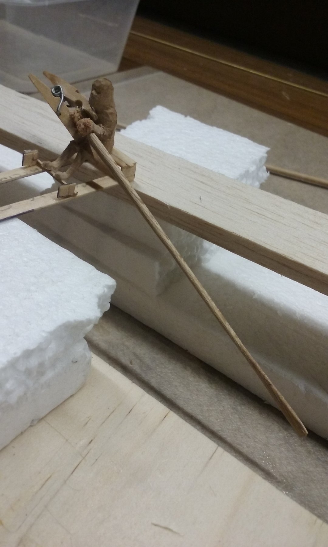
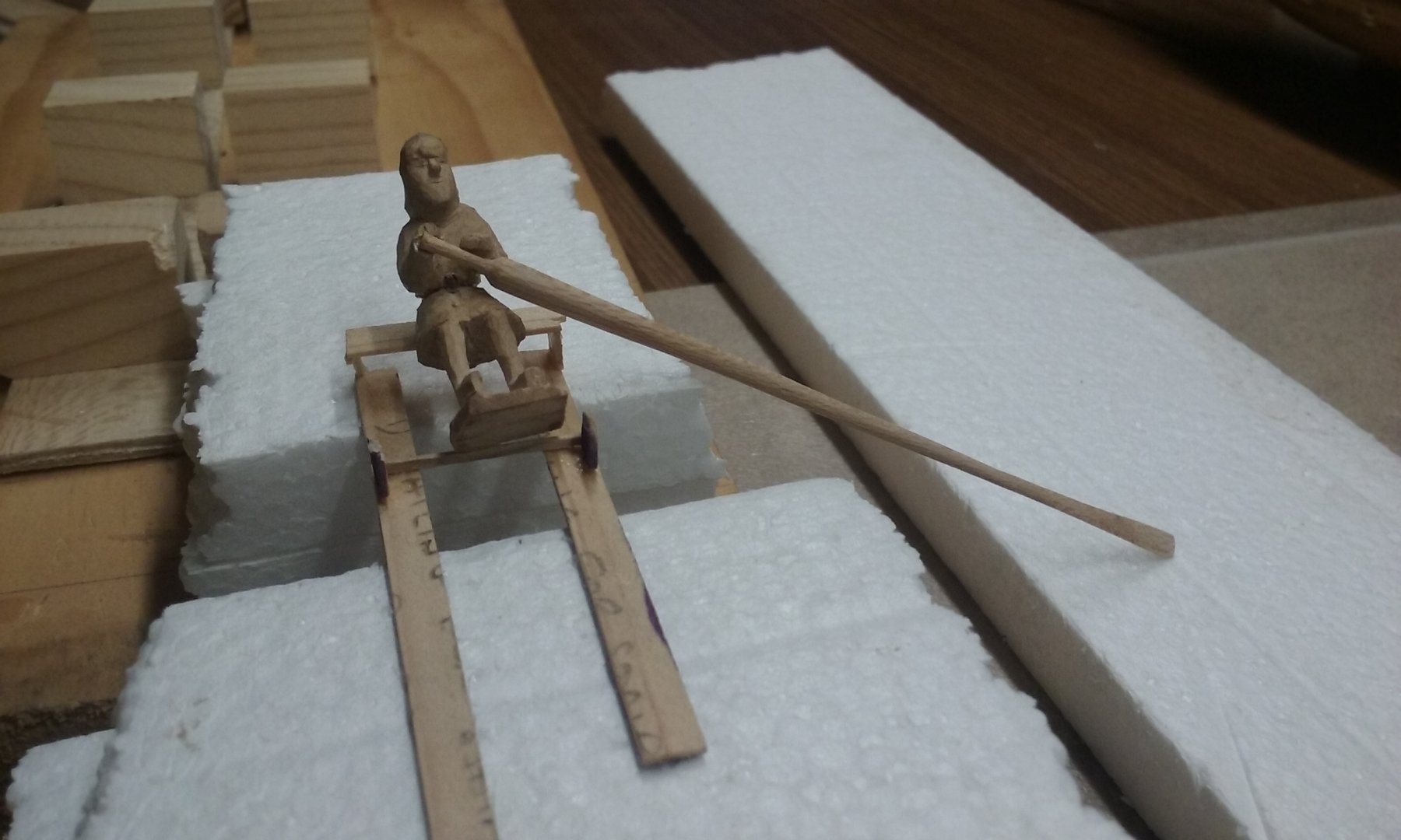
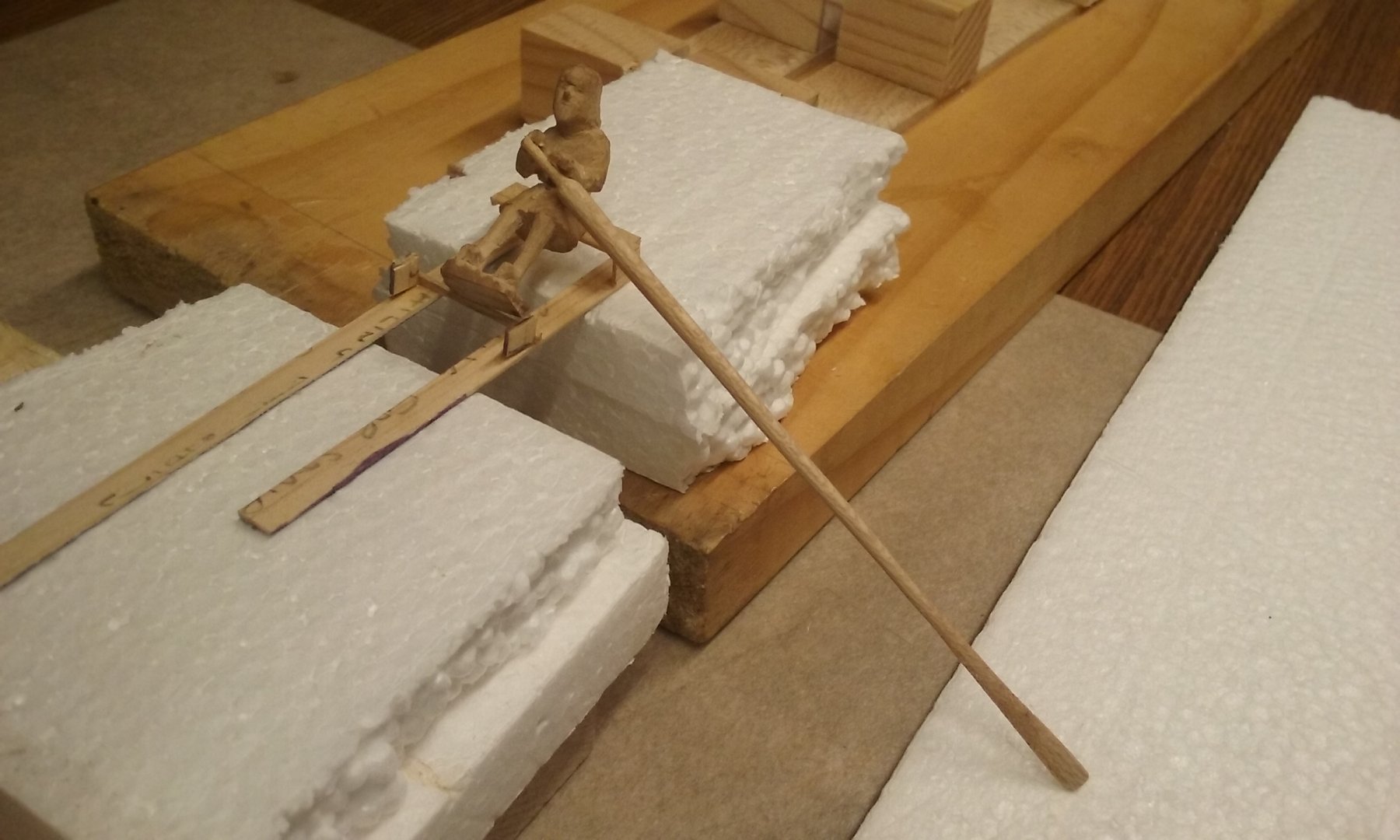
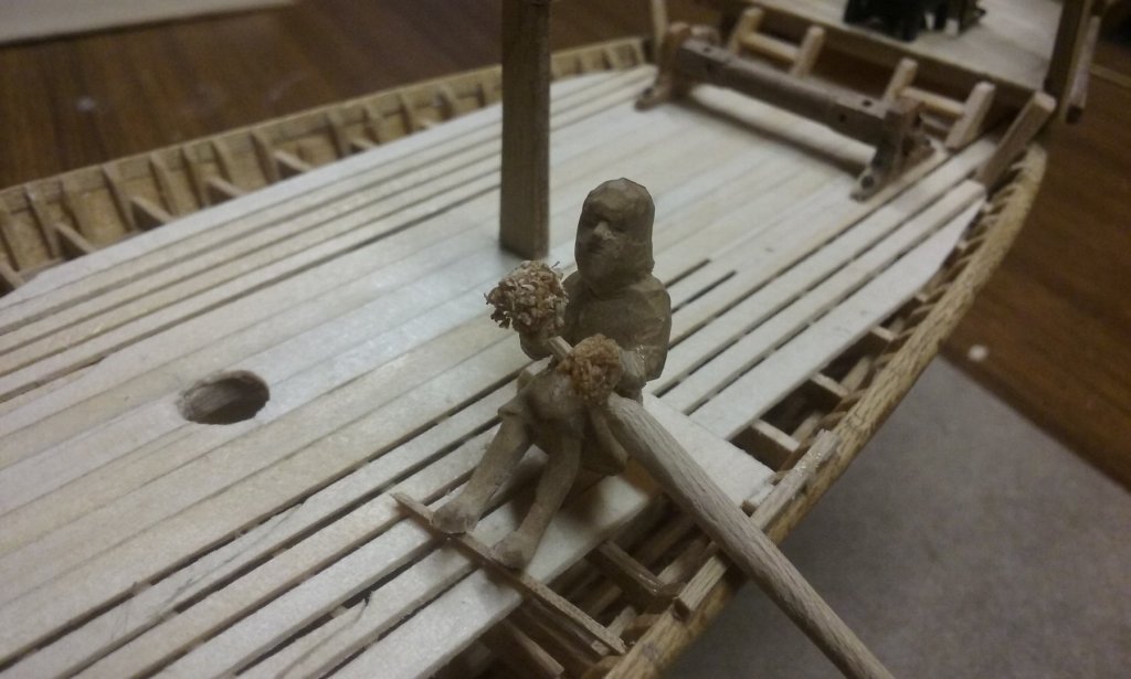
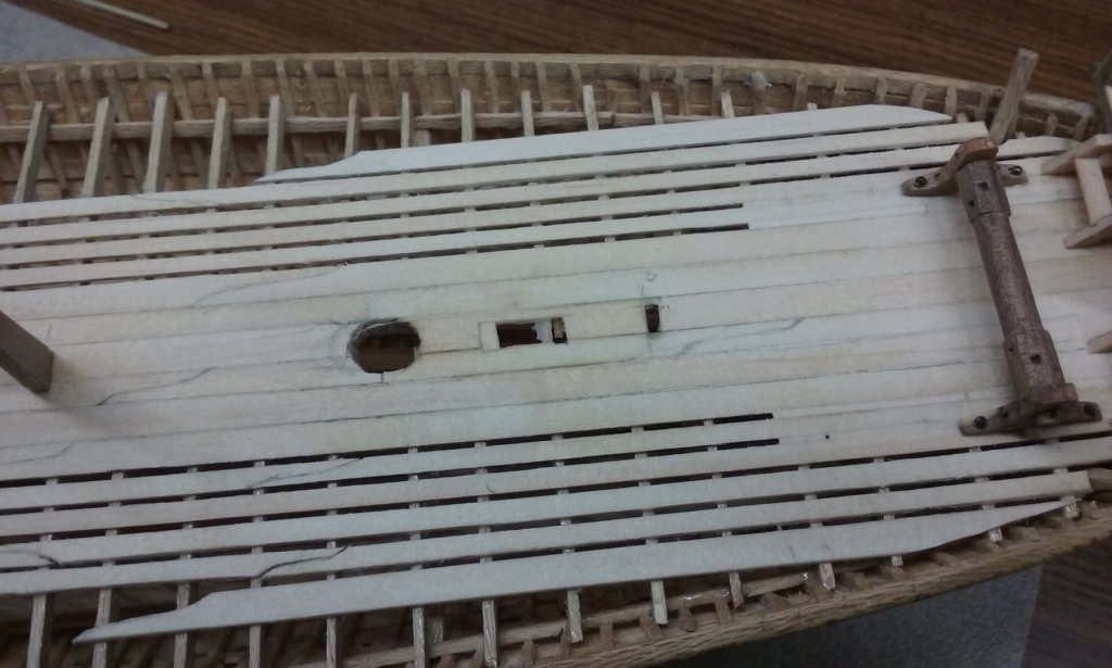
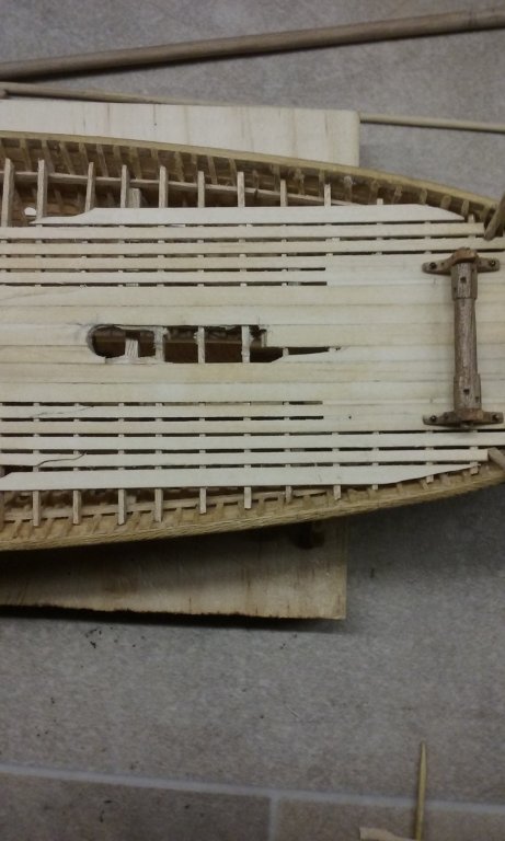
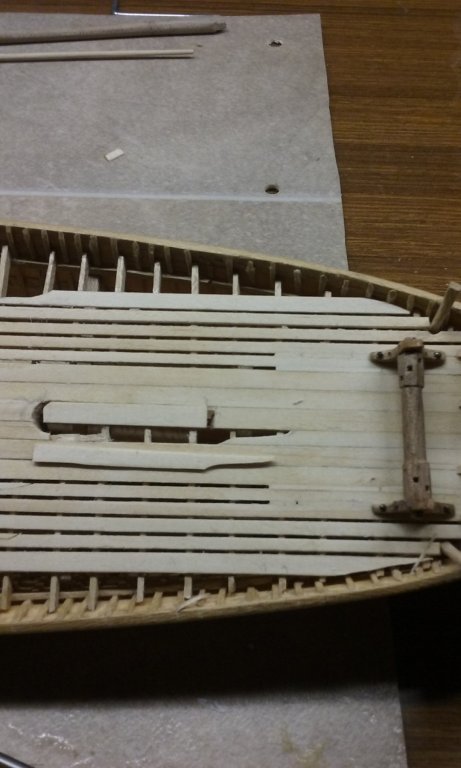
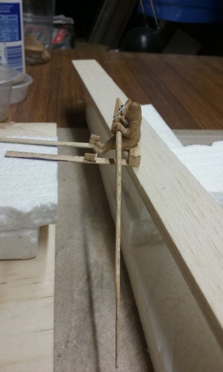
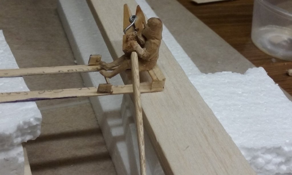
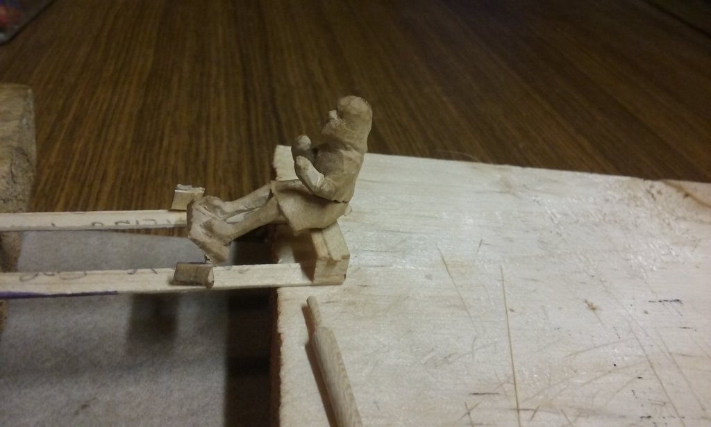
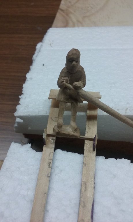
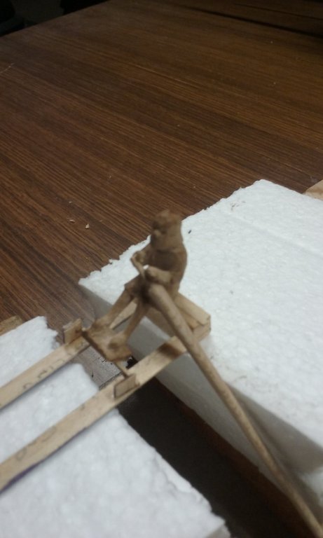
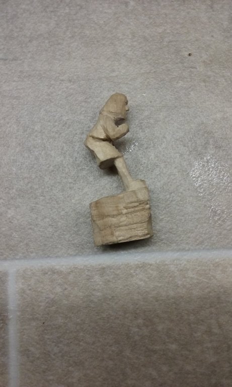
Thanks everybody for the likes, and thanks, Mark. Actually he's leaning too far back because that rotten stand is getting in the way. I based him on a lot of photos of upper oarsmen on the Olympias trireme reconstruction, and at the end of their stroke they are hardly leaning backward at all. I only added the stand so the figure would be easier to cast, but I figured that at the moment it was more important to check that his "angle of lean" was correct, so I cut the stand off. I can always replace it or put another one on. Here are some photos of him with the correct posture (oar temporarily dry-fitted with a peg holding it in place). The reason his hands are all fuzzy is that they were a bit too small and in the wrong place so I've added a bit of glue and sawdust filler to make them bigger. I'll tidy this up on the first resin copy I cast - the filler's a bit too hard to work with and get fine detail. The oarblade comes down to about 2 centimetres below deck level, which converts to a metre between the deck and the bottom of the oar. That's probably not quite enough, but I can adjust it down a bit by slightly altering his grip on the oar handle, and it should reach the surface of the "water". I still have to smooth him off somewhat before he's ready for casting, but that's ok - I don't yet have the stuff I need to do it anyway. And I've finally had an idea of how to align the level of the oarblades with water level without having a surface that stops the blades reaching far enough down. Instead of a flat surface to stand in the place of water level, I can use a relatively open wire mesh, which will allow the blades to go through the holes to the correct level. (Don't know if that all makes sense, but it'll be easier to understand when I post photos - in the fullness of time; I'm not yet ready to do that.) And I've been thinking about a comment Woodrat made about the possibility that the forrard crutch for the yards might foul lower end of the foreyard when it is moved from one side to the other as the ship tacks. I've slightly reduced the rake of the foremast and moved the crutch forrard a bit. I've had to remove parts of two planks to repair the change, but I'd been unhappy with that part of the deck anyway because I'd had a patch in it where I'd already moved the crutch. Hole for the mast elongated aftwards enabling me to reduce the rake, and starting to remove the planking. You can see the patch in the deck just forrard of the mast opening, the slot for the old crutch position and the new slot furthest forrard: Planking all gone and a scarph joint cut in one of the remaining planks First new plank cut and being shaped to fit the gap. (I've cheated by putting a concealed joint in the planking below the relocated crutch). First new plank in place and second plank shaped and ready to insert. Second plank glued in place. Mast-hole cut in new planks, mast dry fitted, and relocated crutch glued in place. Voila! So it's now all tidied up and fouling should not be a problem any more (not that I'm going to be doing it in the real world - this is in what you might call "model space" (in-joke for people familiar with AutoCad). Progress slow but steady. Steven


-
Thanks for the likes and the comments. Funny, I'm in the middle of reading a book called "Finders Keepers" by Craig Childs about archaeological looting, (which is a major problem and is nowadays carried out on an almost industrial scale) - the thing that grabbed my attention though, was his statement "I have secretly wished to be an archaeologist myself, but I do not have the patience for the scientific tedium involved, which would test model-ship builders." (my italics). Nice to see the recognition of one of the main qualities of a ship modeller . . . Maybe I'll make this my signature? Steven
- 740 replies
-
- 4
-
-

-
- Tudor
- restoration
- (and 4 more)
-
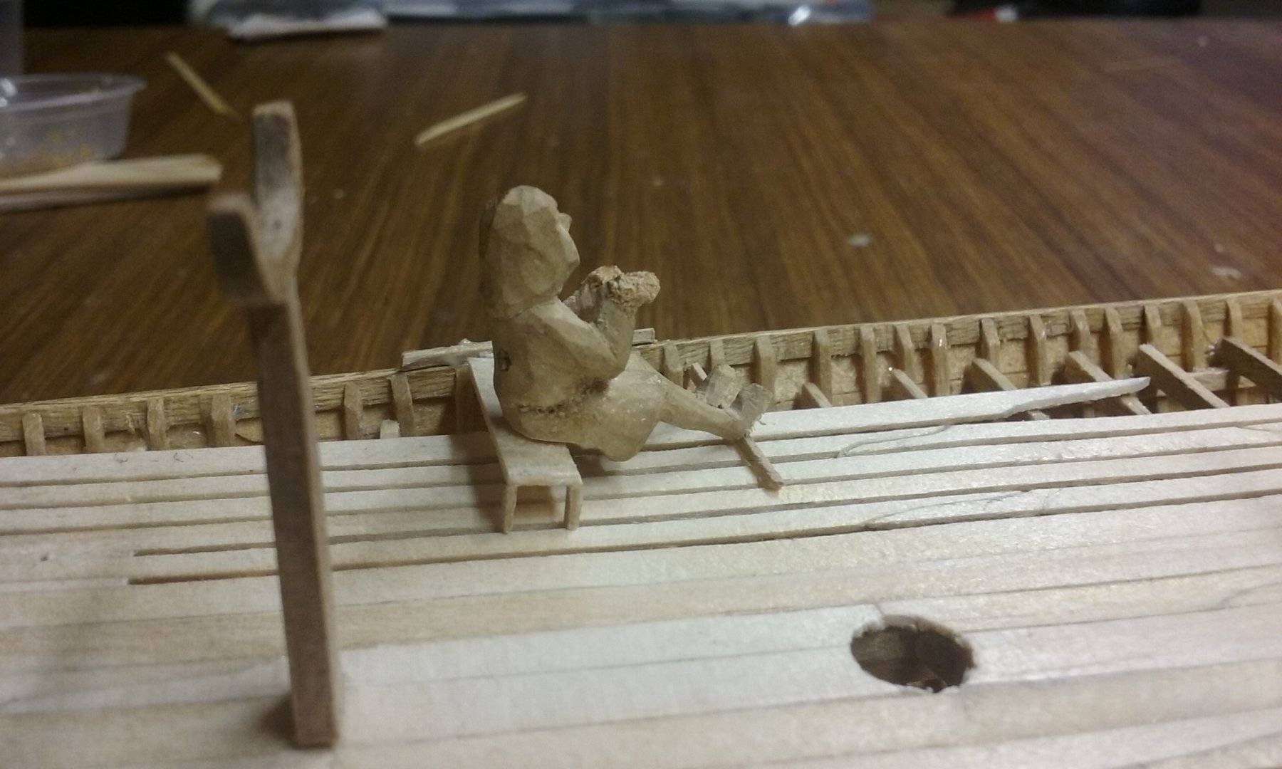
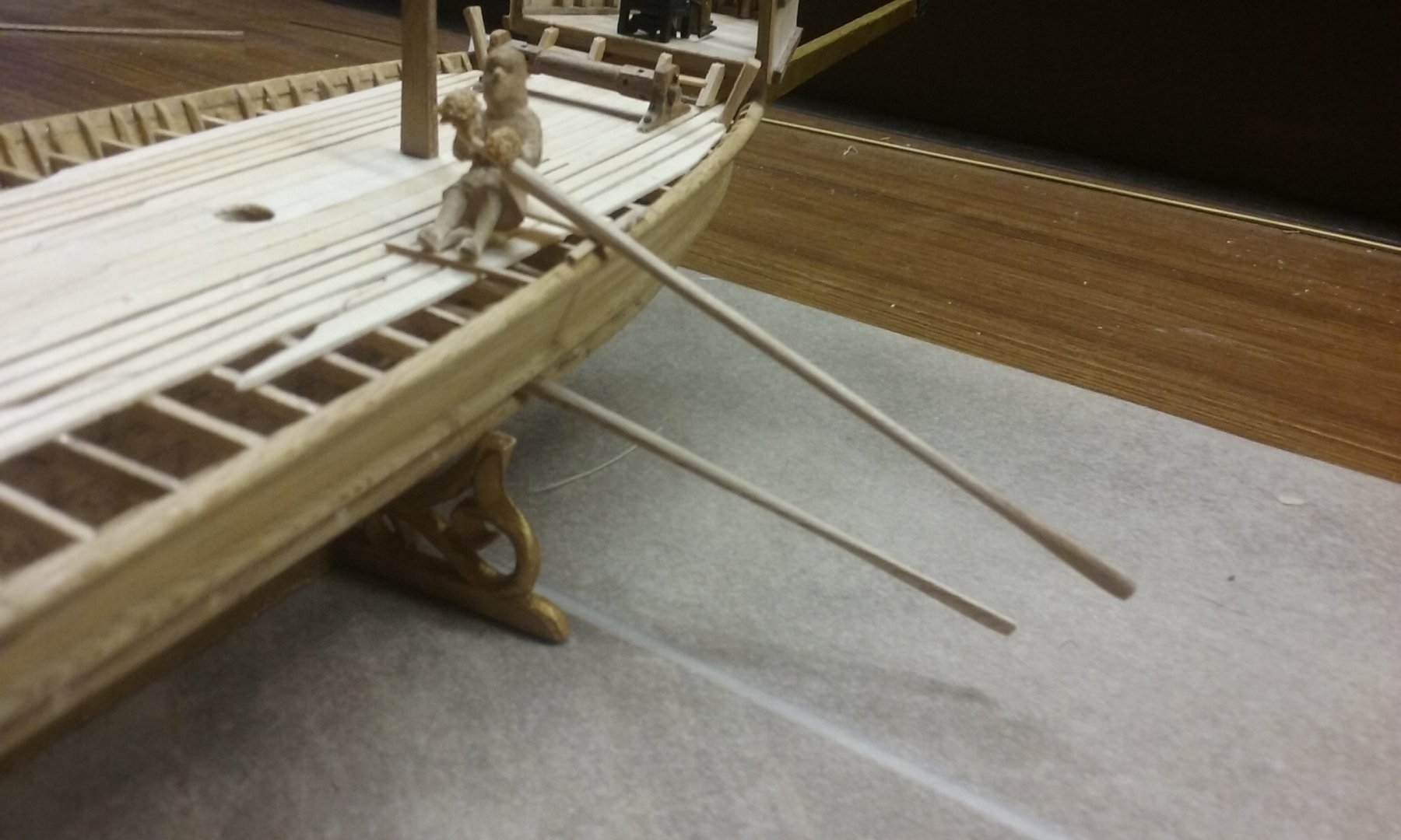
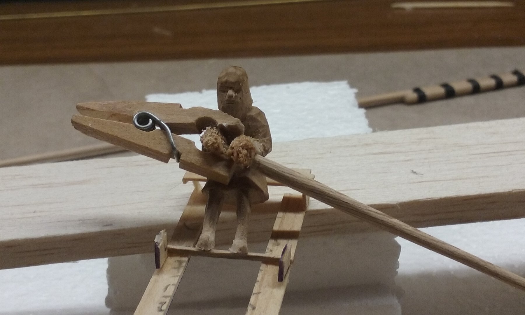
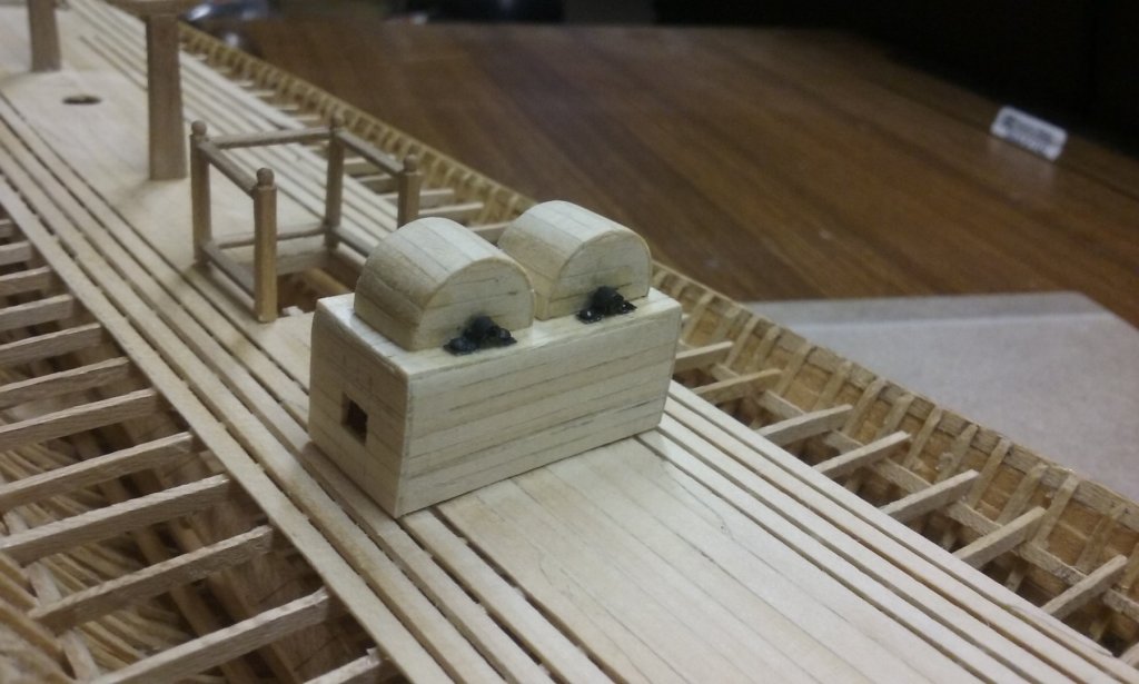
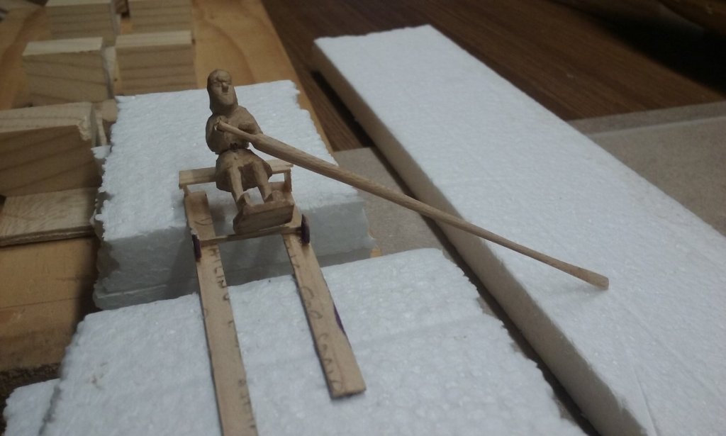
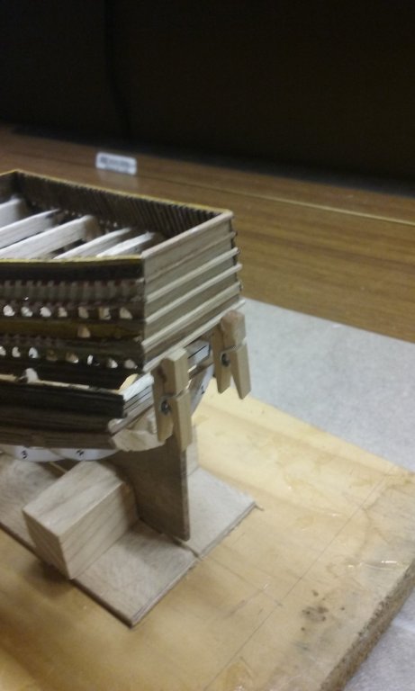
Painted the metal brackets on the chain pump and cut the holes for the lands. I still have to put an edging around the holes. Here's the little guy on a mock-up of the rowing bench, with his feet resting on a bar at the back of the next bench. He's still leaning back a bit too much because the stand under his feet is in the way, but I have to keep that because it's needed in the casting process. If you're wondering what's sticking out of his tummy in the third photo, that's a wooden pin I used to hold him together while I was gluing him together at the waist to sit further forward. I only just noticed it, and I've now carved it off. And here he is with an oar in his hand, held in place temporarily with a dab of PVA glue. The angle's pretty good but I'll need to extend his fingers a bit to curl around the oar handle better. From what I've learnt making this guy I'll be able to do the starboard guy better - in particular if I drill a hole for the oar handle before I start shaping his hands it should be easier to get the angle of the oar correct, and the shape of the hands should be easier to do as well. The oar blade is currently facing the wrong way - it should be perpendicular to the water surface. But this is just a test to get the fit right - it will be fixed when the time comes to put everything together. Steven


-
You may be right, Dick. It's a little confusing, and I don't think M. Burlet was very specific with his explanation. Or perhaps it's just my rotten translation. By the way, in the passage above I think "top-rope falls" should be "top-rope downhauls". Nice work on the pumps. Funny to see that the idea of pulling down on a lever with gravity on your side, instead of pulling up against gravity, hadn't yet come into use by this time. But it's confirmed by the 15th century Baltic wreck mic-art posted recently. Steven
- 263 replies
-
- 1
-
-
- nave tonda
- round ship
- (and 2 more)
-
Thanks for the likes, everyone. They may well have been, Carl. I have to admit it never occurred to me, but in any case I had to make a decision. Though it involved a fair bit of work to extract, the Byzantine Empire wasn't short of metal, so I think I can feel justified in using iron. Steven
-
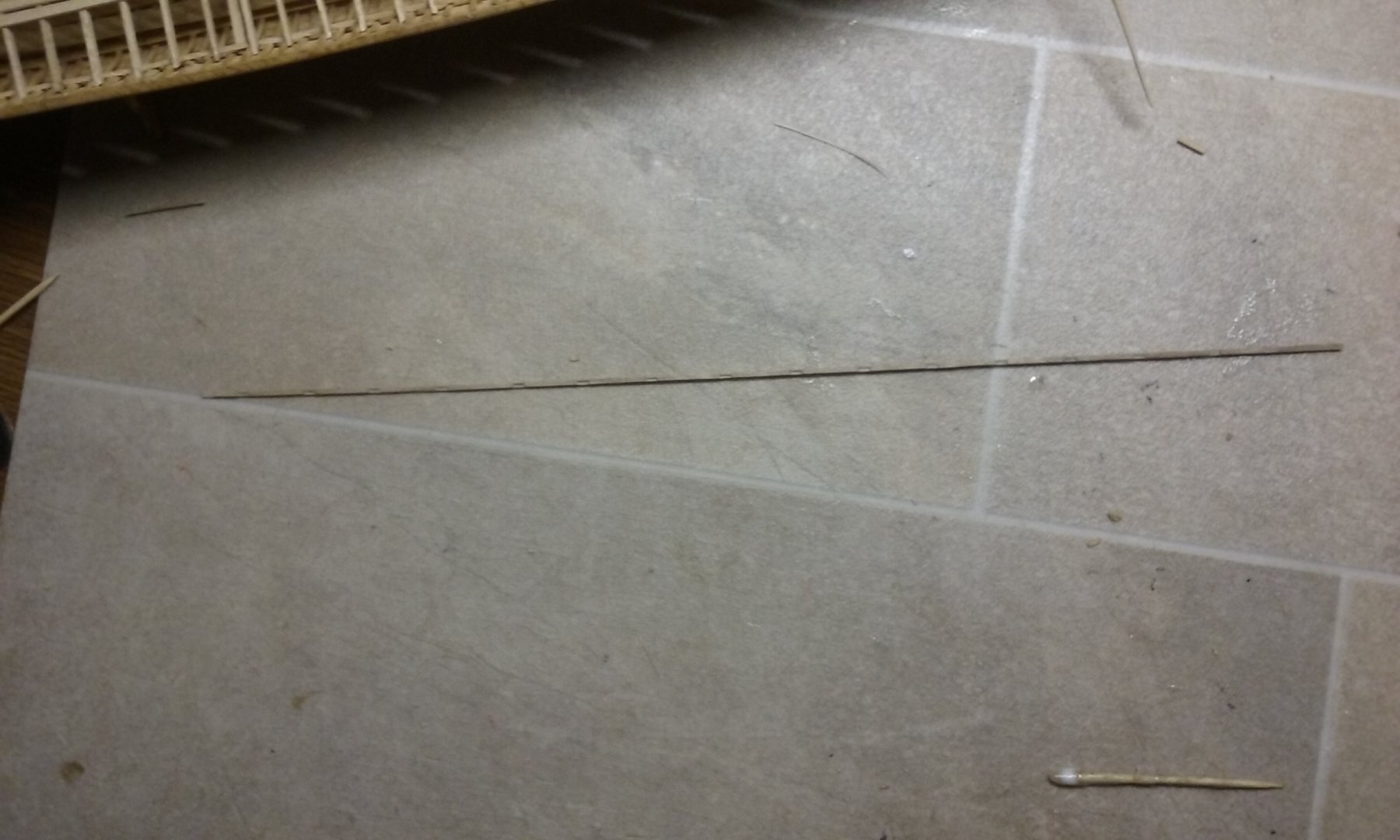
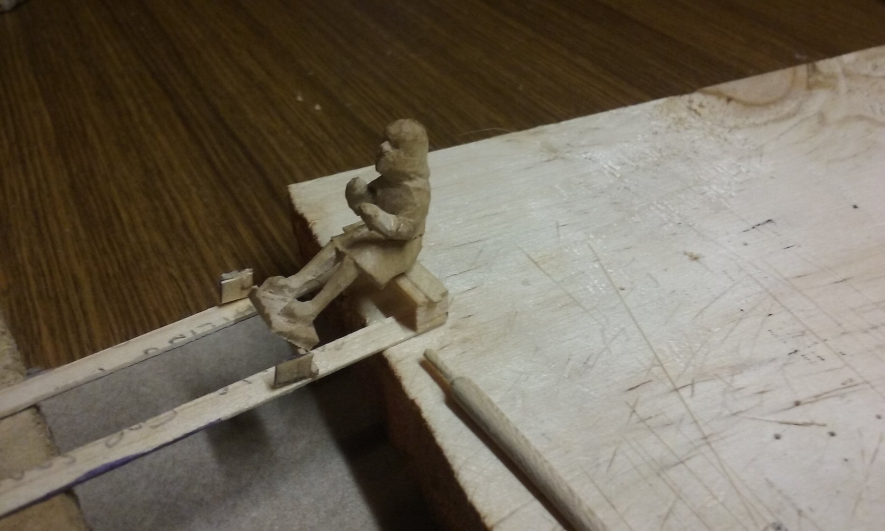
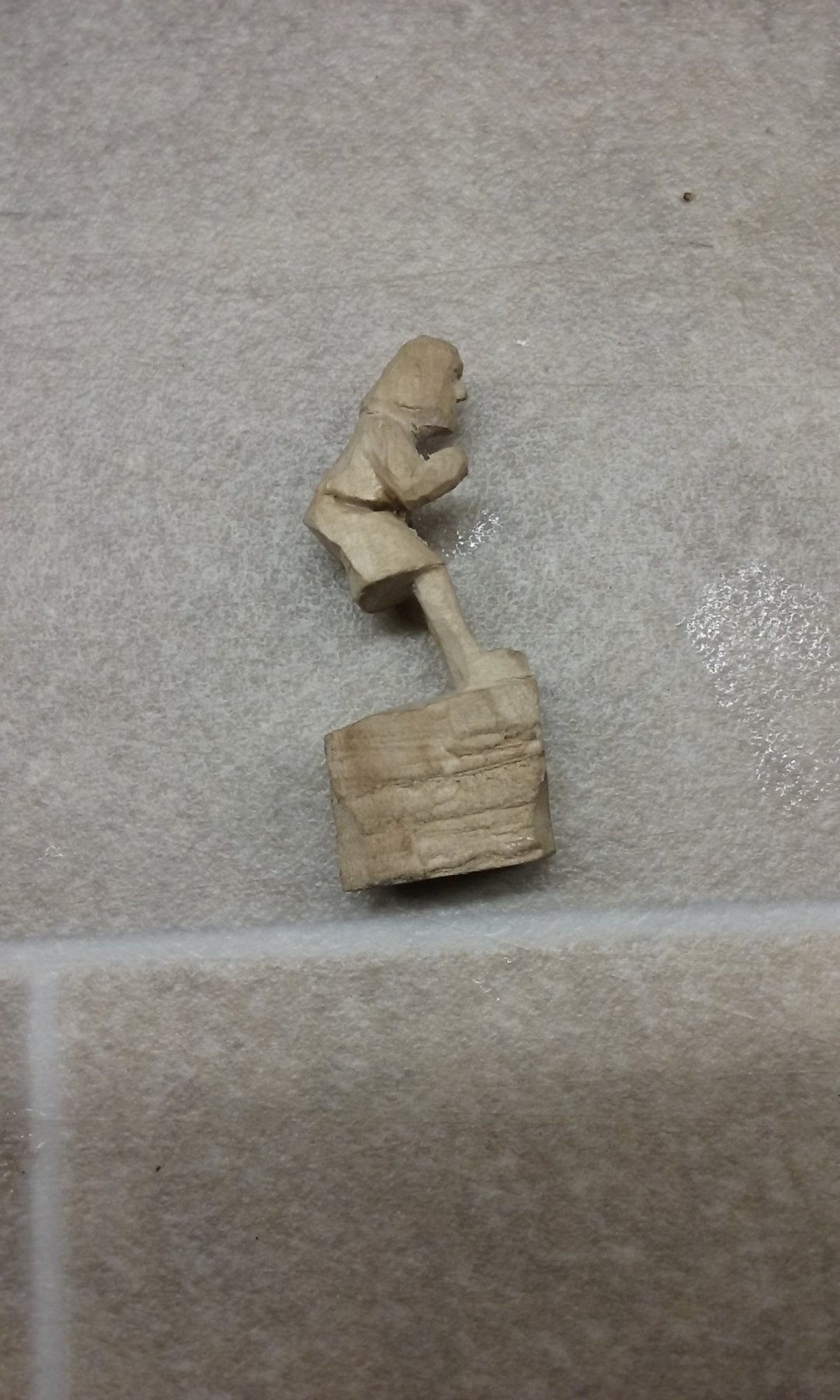
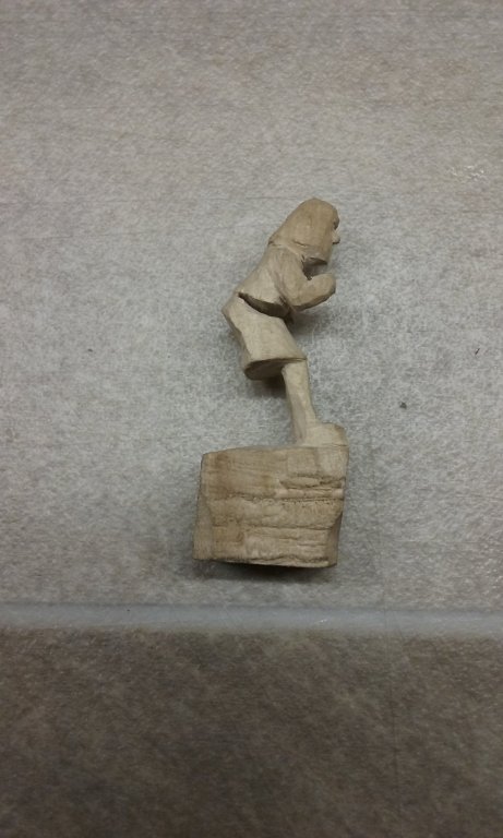
Oh, and here is the carved original I intend to cast in resin for the oarsmen for the port side of the ship. It's quite difficult getting him exactly the right shape and with his hands in the right position so that he can sit on the oarbench with his feet resting at the base of the one behind him, while holding the oar so the blade goes in the water and the angle of his stroke is right. I discovered he was leaning back too far to do all that, so I cut a wedge out of his tummy and glued him back together so he was sitting up more. I won't be able to check if he's exactly right till I can cast a copy of him and put it in position. A lot of trial and error involved. And though I had made a starboard side oarsman in wax, I wasn't happy with him and I'm going to do him again in wood (which I feel more comfortable with, and which is rather more forgiving). Steven
-
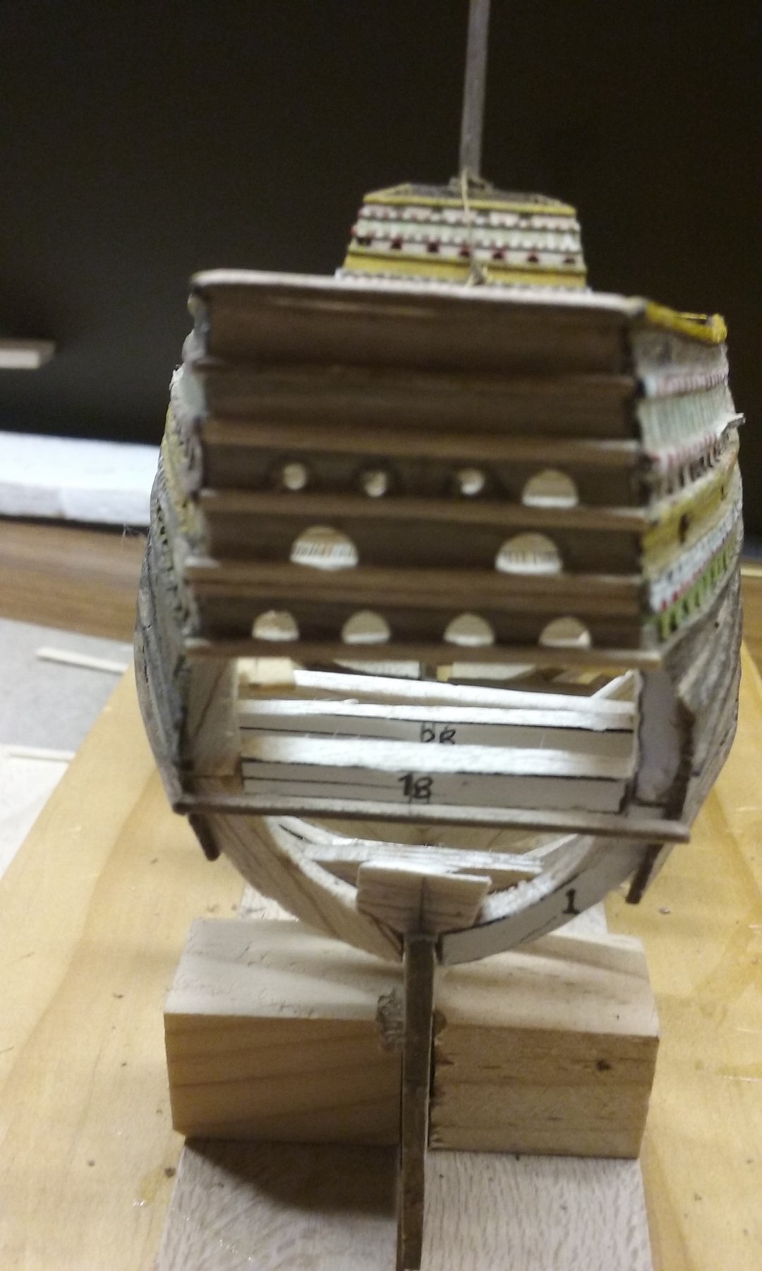
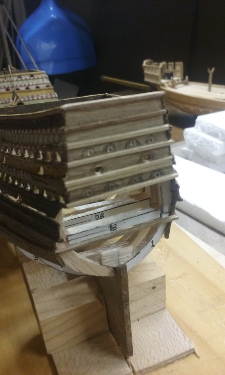
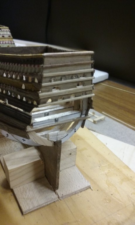
After quite a long gap, I've put the wales on the transom. Unfortunately the wales on the port and starboard sides of the ship don't line up perfectly with each other, so I had to fudge it a bit to get the transom wales as close to parallel and horizontal as I could. Next job is to cut arched gunports in the transom, then make the lower part of the stern. I also have to fit a sliver of wood between the main hull and the upper works to fill the gap noted in the previous post. Slow but steady progress. Steven

- 740 replies
-
- 9
-
-
- Tudor
- restoration
- (and 4 more)
-
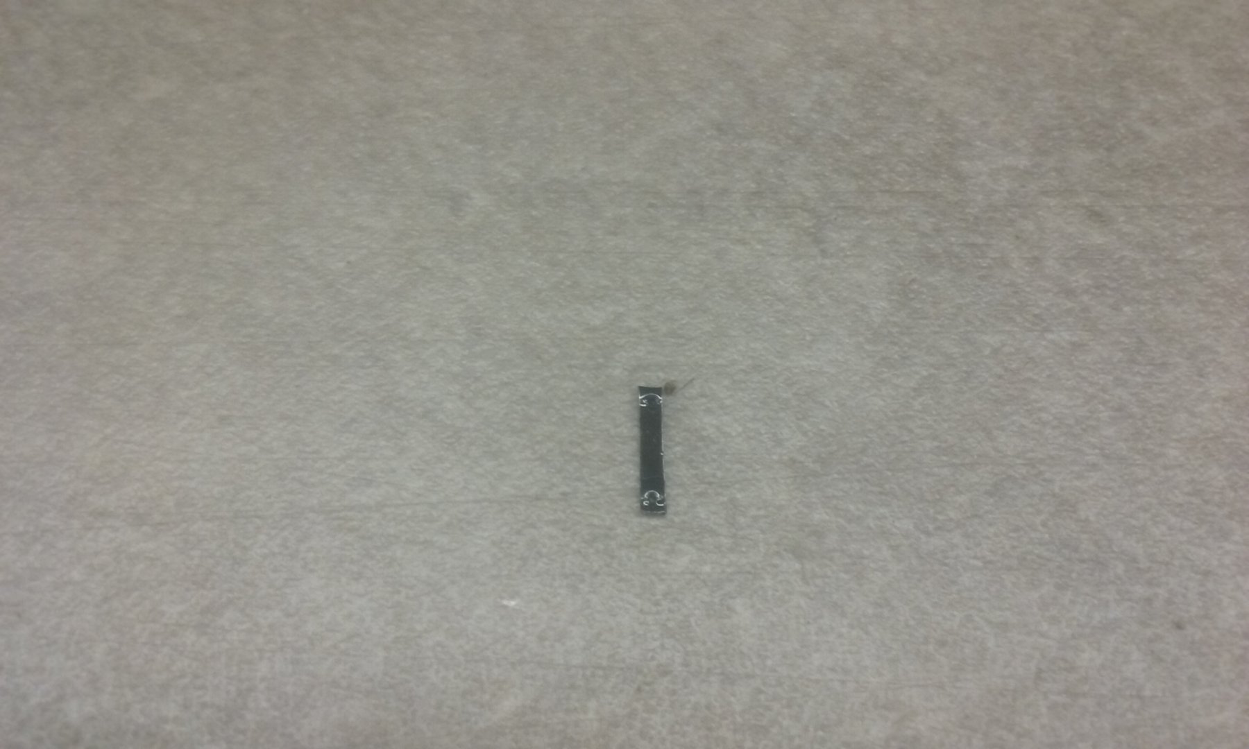
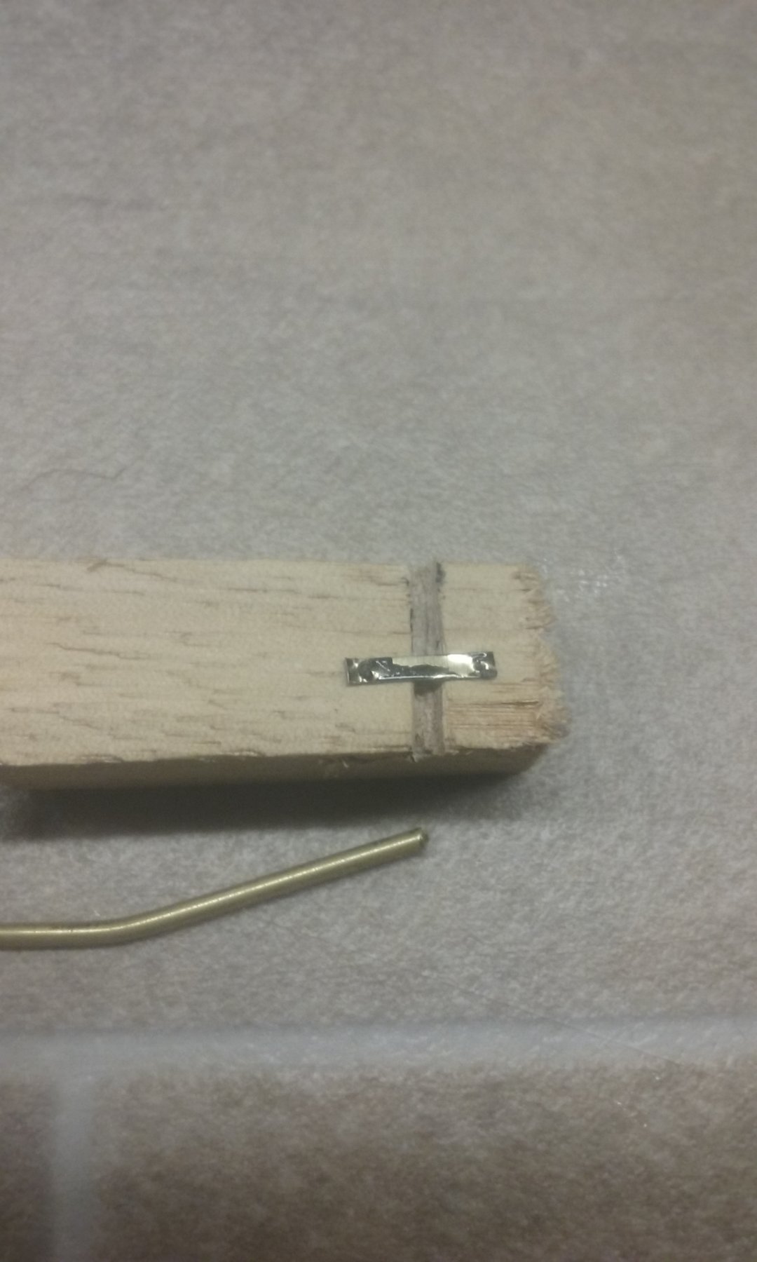
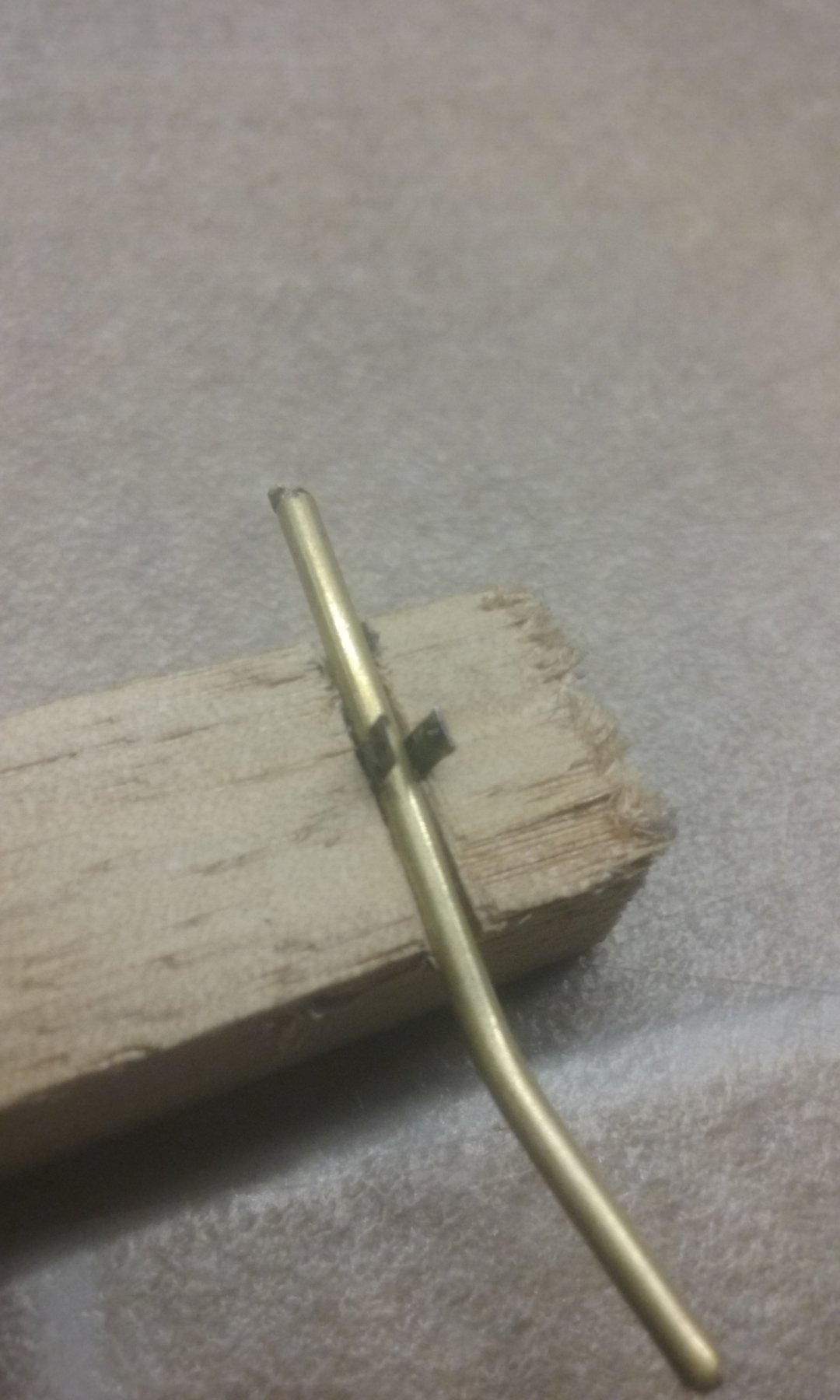
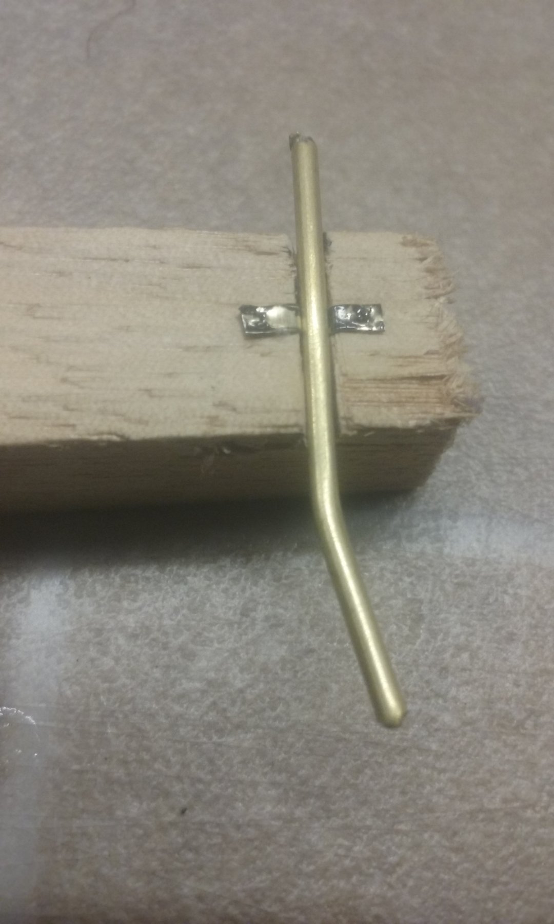
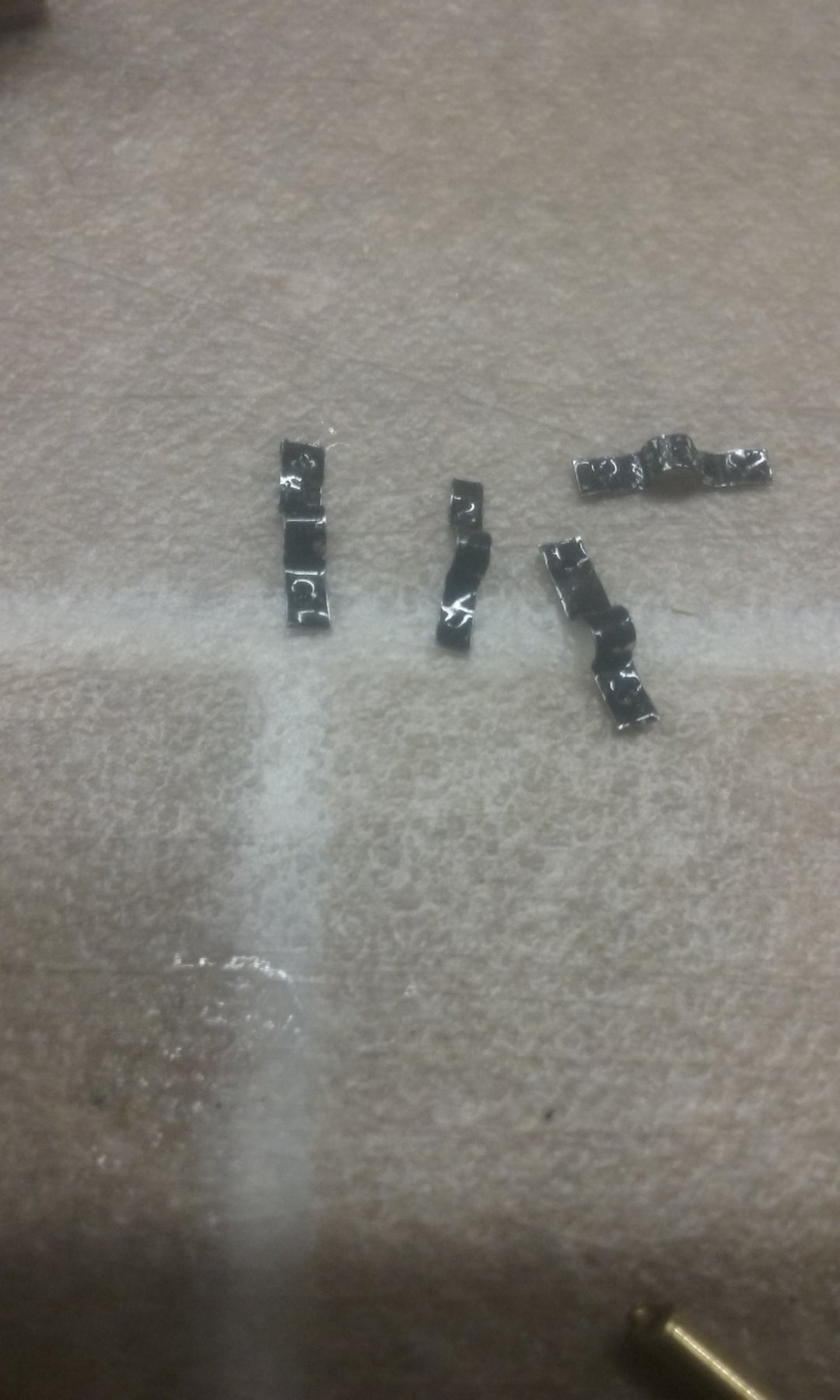
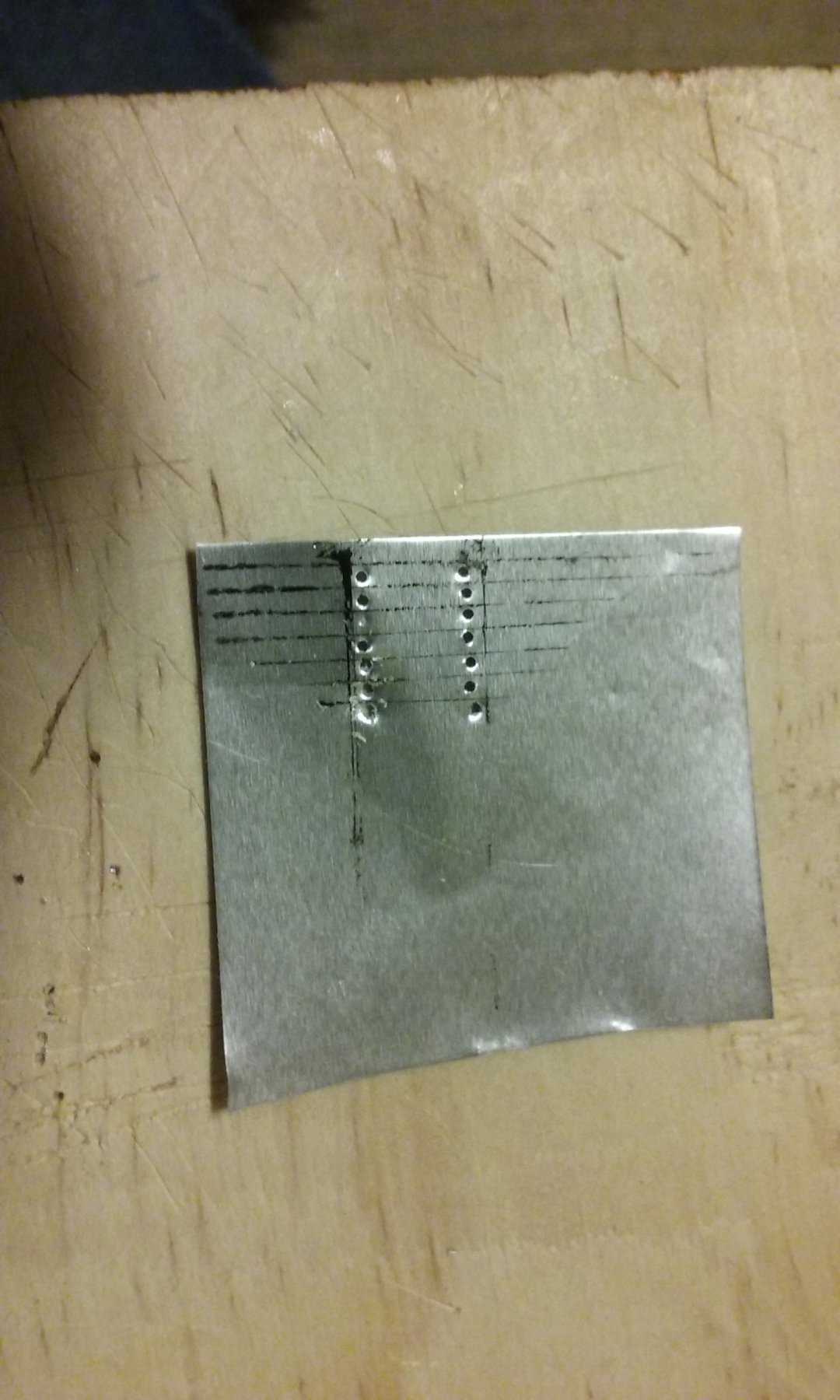
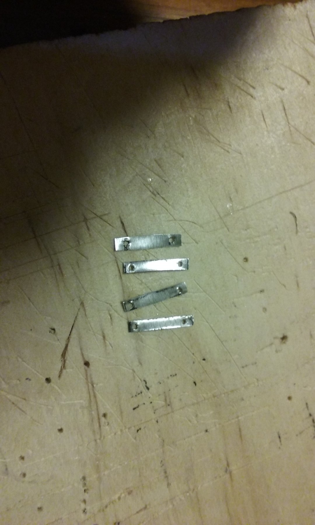
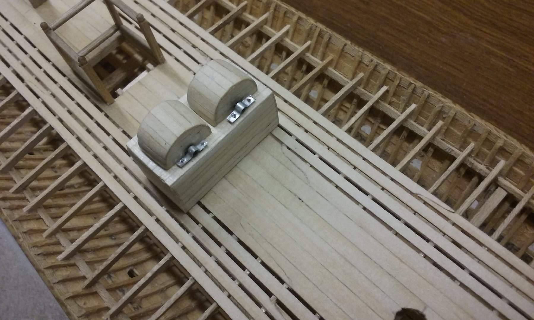
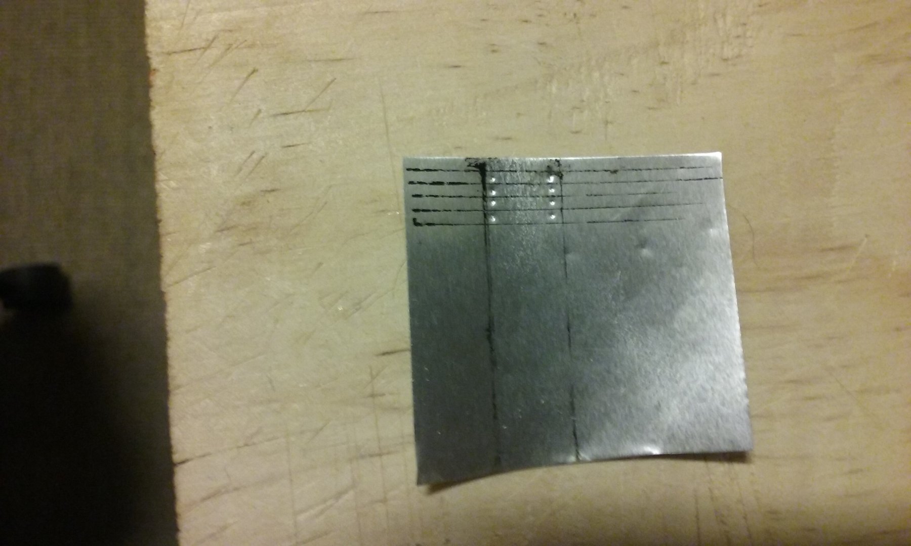
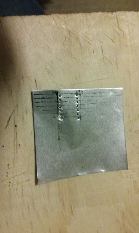
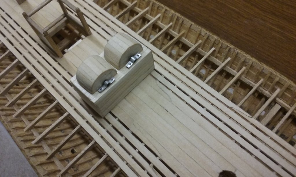
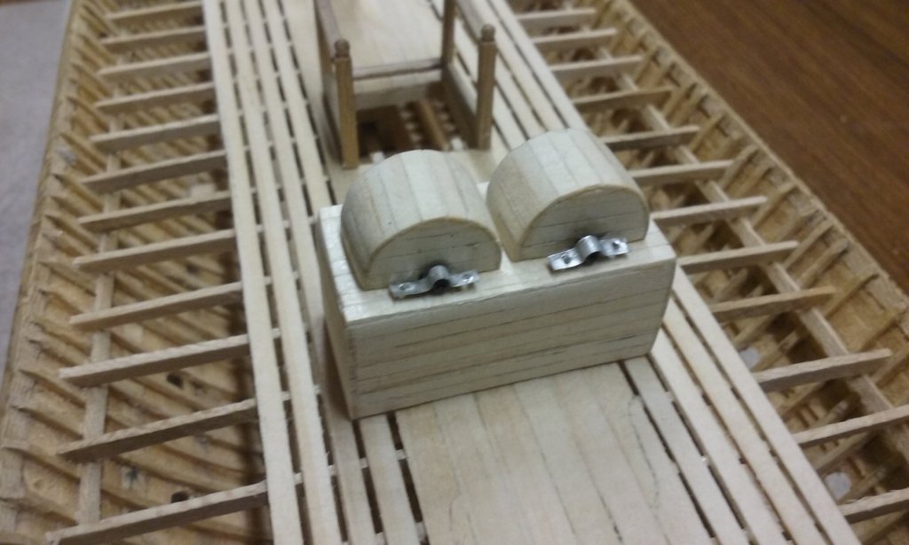
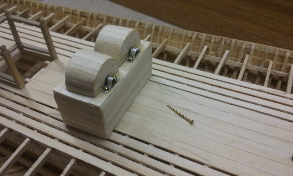
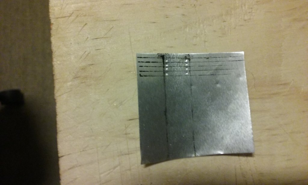
Thanks everyone for the likes and comments. Much appreciated. Just a bit of finalizing on the chain pump - the brackets holding down the (spindles?) for the cranks. Cut from the little foil boxes the cat meat comes in. Here's the first attempt: I had to do them twice because I got the sequence wrong (but I am rather pleased with the little jig I made to shape them). Drill the holes, then cut the foil into strips, not the other way around (foil strips twisted into unrecognisable shapes by the drill bit). Turned out there was a lot of wastage trying to get the holes in exactly the right places (using a standard carpentry drill - too big and heavy - I have a dremel knock-off but haven't been able to work out how to work the flexible drive to do fine work. I really need to sit down for a while and figure it out.) That's about all the good ones I was able to get (except for the one that fell on the floor and was transported into a parallel universe). Here are the brackets in place - glued at the top of the curve with a spot of CA, then when it was dry, using a stylus thingy to push the foil into the the final shape. And drilled through the holes into the top of the pump case and fixed with fine brass pins, glued in with CA. Once the glue is dry I'll paint all this "iron" black. I realised I should have put the openings in for the dales before I attached the pump assembly to the deck, so I'm going to have to do that in situ, which will be a bit more difficult. Steven


-
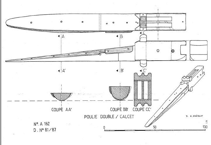
Good question. The only statement that might be appropriate (excuse my translation, which might not catch the full intent of the original) is "In the 17th and 18th centuries, the piece intended to avoid wear described here as a “comb” was called an eye (calcet with two eyes), the amans (ropes?) passing through holes and not as here in a groove. The groove at the top of the calcet was probably intended to take the strops of the auxiliary tackles (carnal and carnalette). " What this means exactly, I really don't know, but the reference to the carnal and carnalette might be the answer to your question. Perhaps Rene Burlet may be able to provide the answer, if you can find the right book. He has written a paper called "But how did they row the galleys of the Sun King (Louis XIV)" and a book called "Les galères au Musée de la Marine" (https://books.google.com.au/books/about/Les_galères_au_Musée_de_la_Marine.html?id=4ODlHStz_uMC&redir_esc=y ) analysing the models of galleys in that Museum. The site contains a link to a chapter entitled La galère à la voile (The galley under sail) which on a quick perusal seems to offer some clues. It is all in French, but I've translated below the bits that appear relevant: “The control of the yards, of which the weight is considerable, (a mestre [master?] yard, its largest sail and its manoeuvres easily amounting to 2.5 tonnes) is a delicate affair which requires a series of precautions . . . the yard is supported by a strong tackle which we have already mentioned with its top-rope falls. It is held to the mast by doubled cordage, the trusses equipped with parrels to slide the length of the mast when needed. These trusses are blocked by the angui tackle (??? - I've no idea what this means).” “ . . . to close this brief enumeration, there are two tackles used for each mast, the canal and the carnalette. It should be noted that these could equally be used to hoist barrels of wine.” I'm afraid that still doesn't answer your question, however. He goes on to say that because the size of a lateen sail can’t be adjusted (i.e. reefed) – it’s all or nothing - each galley carried three sets of sails of different sizes for different conditions. Steven
- 263 replies
-
- 2
-
-
- nave tonda
- round ship
- (and 2 more)
-
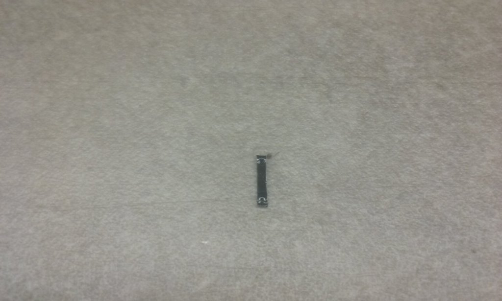
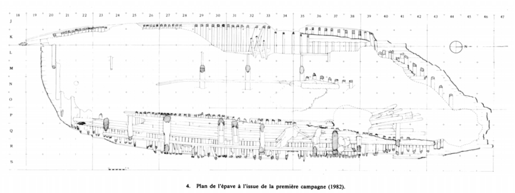
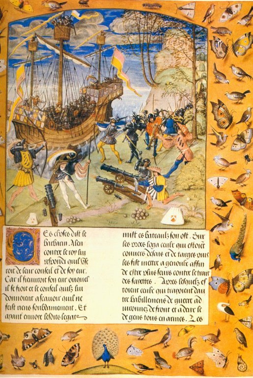
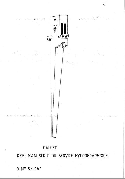
Translated from French, the report of the 1987 dive states "Discovered at Q35, [see plan below] close to double pulley A 167 and under the two wheels A66, this rigging piece is in the form of a case with a double pulley with two slots, associated with a sifflet (angled scarph) joint of semicircular section . . ." "INTERPRETATION – HISTORICAL AND ARCHAEOLOGICAL REFERENCES (MG – ER) This rigging piece has been identified by Rene BURLET, specialist in galleys and lateen rig. It is a calcet which is fixed to the top of a mast of lateen rig. The two sheaves, often of bronze, serve for the passage of the double halyards of the antenne (lateen yard) (ref D No. 95/87) (page 43) . . . " "The calcet has dimensions corresponding to a mast height of 12 to 15 metres, which could be a mizzen or Bonaventure mizzen." So there you are. Yes it's from a lateen mast, and was found somewhat sternward of midships. Though no pictures exist of the Lomellina herself, the late 15th century representation below flies the banner of the Lomellini family, and is probably of the previous Lomellina (the Lomellina I?) sunk in 1503. Steven
- 263 replies
-
- 4
-
-
- nave tonda
- round ship
- (and 2 more)
-
She was presumably square rigged (no contemporary pictures exist, and what remains of the masts and spars are not in situ), but I'm assuming the calcet was from the mizzen, which would have been lateen rigged. However, I'll have a look and see if the archaeological report mentions anything, particularly about where the calcet was found in relation to the rest of the ship. Steven
- 263 replies
-
- 1
-
-
- nave tonda
- round ship
- (and 2 more)
-
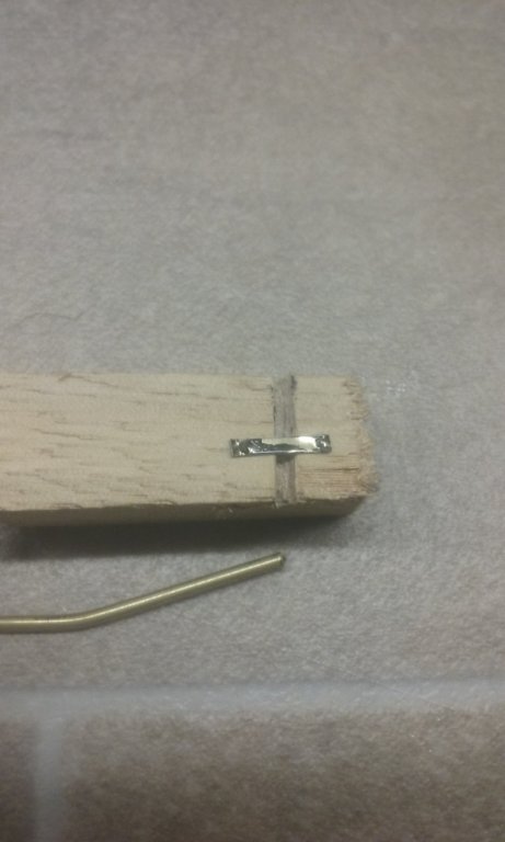
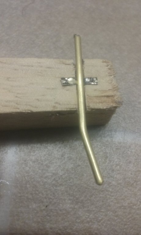
Not sure if I've shared this with you, and I know it's somewhat previous talking about masting and rigging when you haven't even finished the hull, but regarding the way the calcet is fixed to the mast, The Lomellina (sunk 1516) had one like this; and another similar one was included in the archaeological report, thus: I also realise this is several centuries different, but when it comes time to rig your own, this might be of help. I know in my own build I puzzled greatly over how the calcet could have been fixed to the mast without introducing nasty forces that would cause problems. This solution may have been in use for centuries, and is certainly the best I've seen as an answer to the problem. Hope it helps, Steven
- 263 replies
-
- 5
-
-
- nave tonda
- round ship
- (and 2 more)
-
You might try carving "pins" into the ends of the upright supports, with corresponding holes in the gunwale. I tried this and it seems to work - https://modelshipworld.com/topic/10344-10th-11th-century-byzantine-dromon-by-louie-da-fly-150/page/30/ Or (if your hand is steady enough) drill holes in the ends of the uprights and insert metal pins, which go into corresponding holes in the gunwale. If you cut sewing pins short they'd probably do the trick as they are hard and tough and won't bend (or break, as one of my wooden ones did). Steven
- 190 replies
-
- 1
-
-
- ragusian
- marisstella
- (and 1 more)
-
Very nice (and very informative). Thanks, Dick. Steven
- 263 replies
-
- 2
-
-
- nave tonda
- round ship
- (and 2 more)
-
looks very good, Dick. Any chance of a photo from a bit further away, showing where it is on the ship? I can sort of get an idea, but a picture would help. Steven
- 263 replies
-
- 1
-
-
- nave tonda
- round ship
- (and 2 more)
-
Unique 500 year old shipwreck in the Baltic sea
Louie da fly replied to mic-art's topic in Nautical/Naval History
Very interesting indeed. This puts it in the era of carracks - one of my favourite types of ship. You can see the wales, and the foremast right aft of the bowsprit - maybe a suggestion of a forecastle? And the ship's boat is two-ended, as shown in most contemporary pictures of them. The mainyard's still there, but most of the aftercastle is gone, though you can see she has a round stern and the timbers supporting the aftercastle are still in place. Anchor still in position, and is that a pump just aft of the mainmast, forrard of the hatch and capstan? SO much detail, and the state of preservation is up there with the Black Sea wrecks. I look forward to hearing more about this one. Steven -
Looks very good, Dick. I've become much more appreciative of windlasses now I've made one of my own. Yours is even simpler than mine, which is probably right because I just copied the one from the Mary Rose, which is from over 400 years later. Is there a particular reason for making it faceted? Steven
- 263 replies
-
- 1
-
-
- nave tonda
- round ship
- (and 2 more)
-
By the way, if you're looking for resources, I've found Hearns Hobbies, under the arches at Flinders St Station, to be very helpful. Just got back from a visit to Melbourne with a tin of Humbrol paint and a piece of very small diameter brass tubing. (To be honest that's not why I went to Melbourne, but we were walking along the river nearby, so . . .) On the other hand, I take it your "local" in Ringwood is "Float a Boat" about which I've heard very good things. Steven