Louie da fly
-
Posts
7,993 -
Joined
-
Last visited
Content Type
Profiles
Forums
Gallery
Events
Everything posted by Louie da fly
-
 Looks very good, Dick. I've become much more appreciative of windlasses now I've made one of my own. Yours is even simpler than mine, which is probably right because I just copied the one from the Mary Rose, which is from over 400 years later. Is there a particular reason for making it faceted? Steven
- 263 replies
-
- 1
-

-
- nave tonda
- round ship
- (and 2 more)
-
By the way, if you're looking for resources, I've found Hearns Hobbies, under the arches at Flinders St Station, to be very helpful. Just got back from a visit to Melbourne with a tin of Humbrol paint and a piece of very small diameter brass tubing. (To be honest that's not why I went to Melbourne, but we were walking along the river nearby, so . . .) On the other hand, I take it your "local" in Ringwood is "Float a Boat" about which I've heard very good things. Steven
-
Very nice work, David. I don't know how I missed this one - I love carracks and would normally have followed the build. But you've done an excellent job and she looks just like the Mataro ship (well, maybe a little newer 😉) Steven
-
Very nice indeed. You can be justly proud of them. Steven
- 73 replies
-
- 2
-
-
- mediterranean
- galley
- (and 1 more)
-
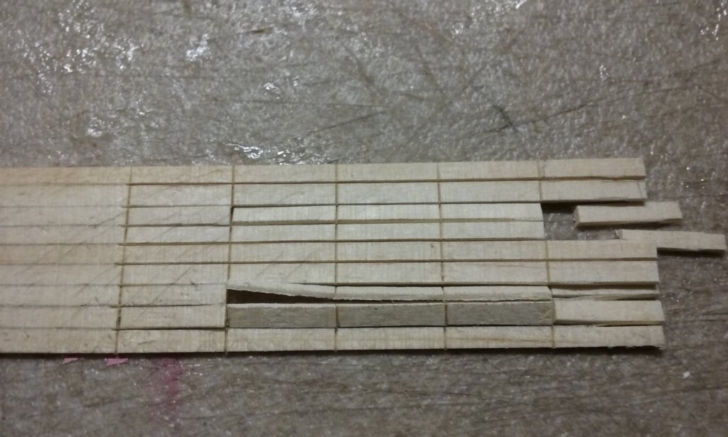
Definitely McGyver! A clever solution to the problem, and looks pretty good, too, though I think I'd make the hole in the hull smaller - it doesn't need to be that big for the rudder/tiller combination to work. Yes, it's probably possible to turn tooth[picks in a clamped drill. There was a thread on this forum some time ago about someone making a poor man's lathe that way, and it seemed to work well. However, toothpicks are a bit rough and ready when you get them from the shop, so don't be suprised if you have a fair proportion of failures. Just keep at it - it should turn out ok with some practice and a bit of wastage. Steven
-
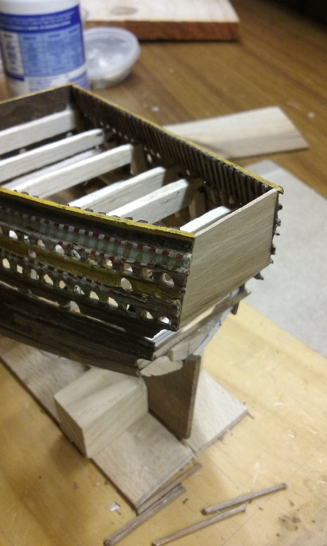
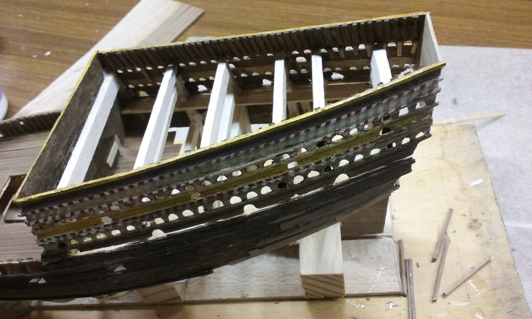
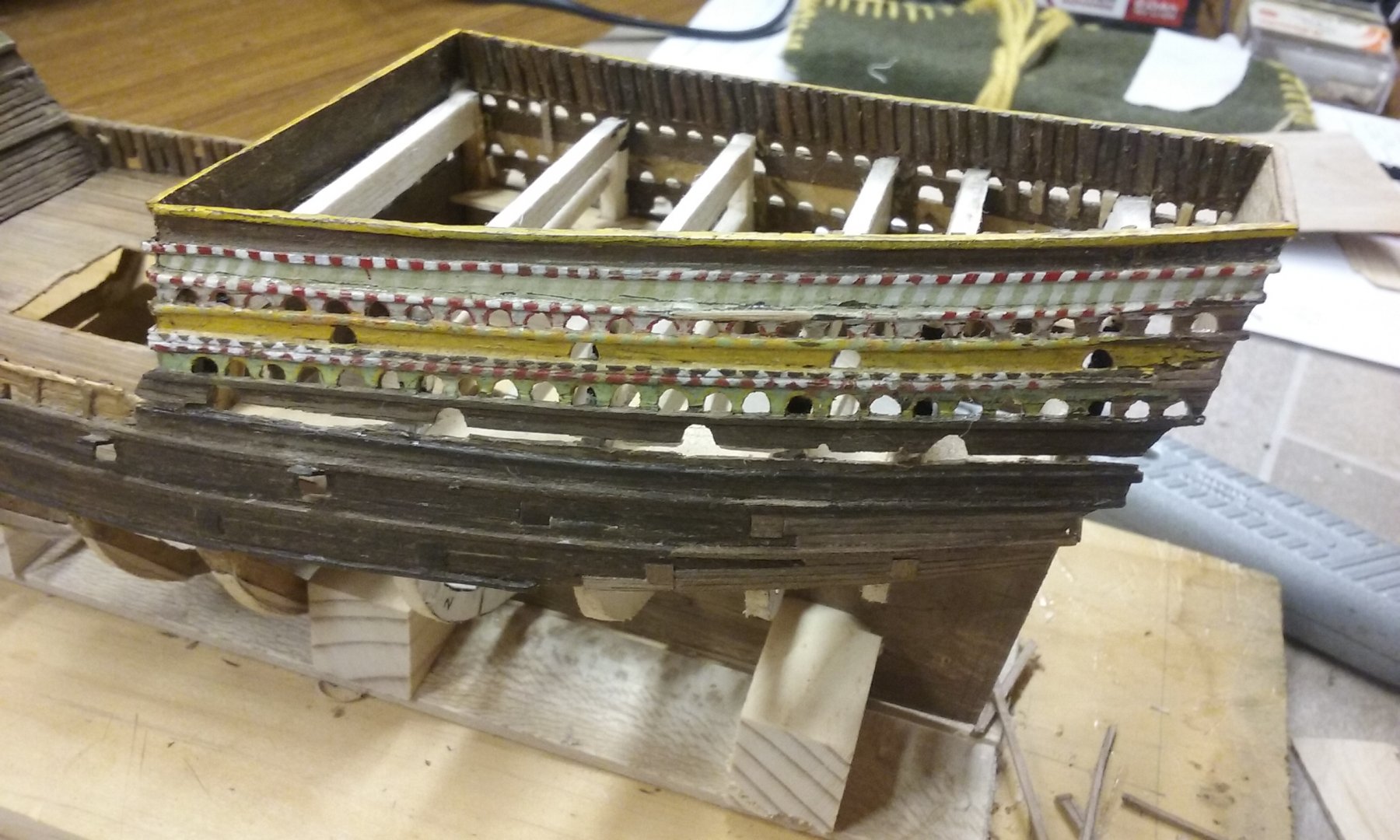
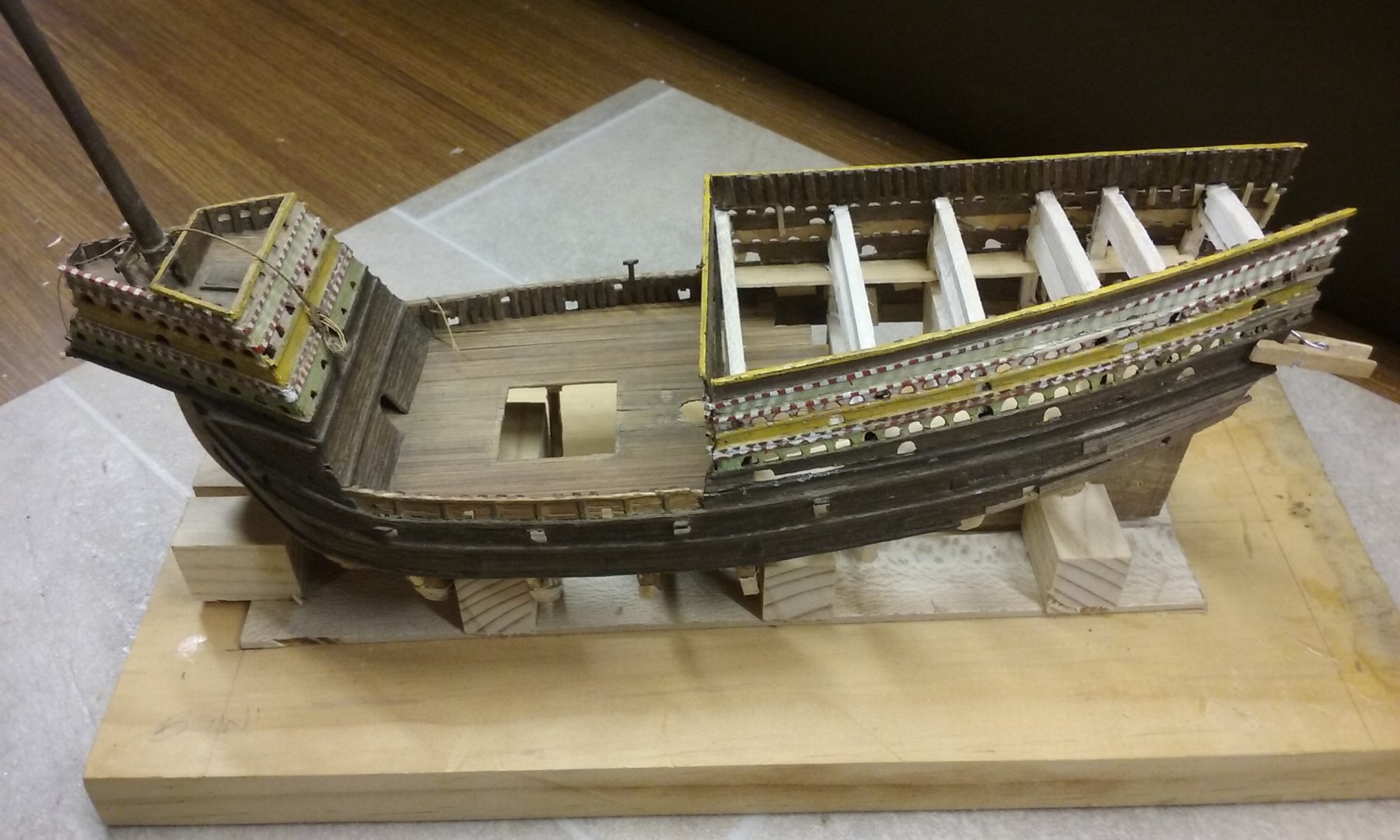
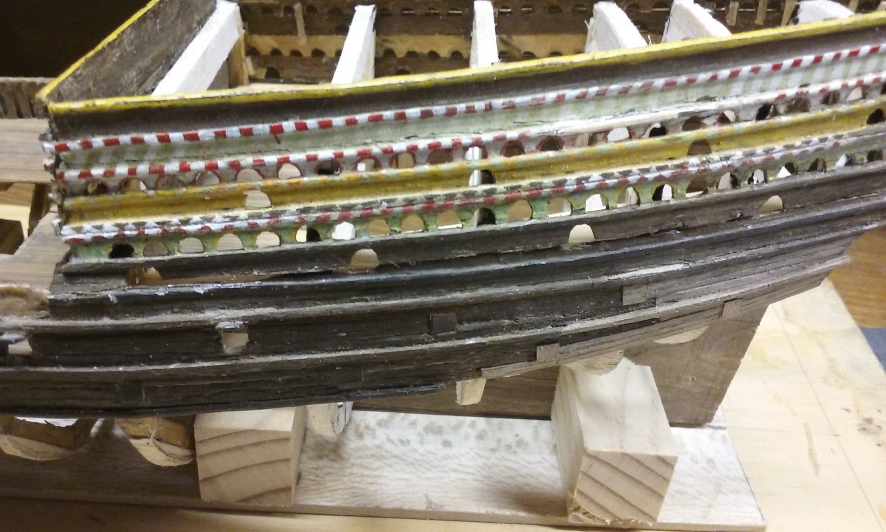
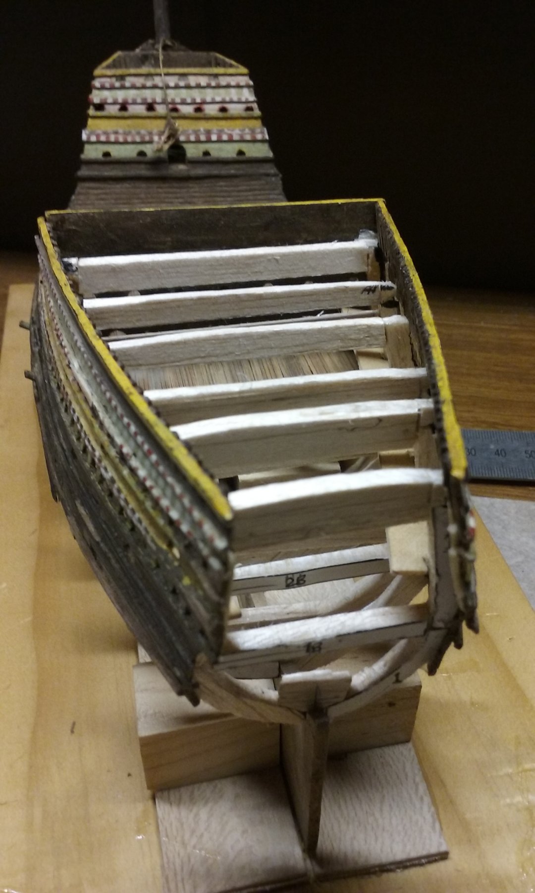
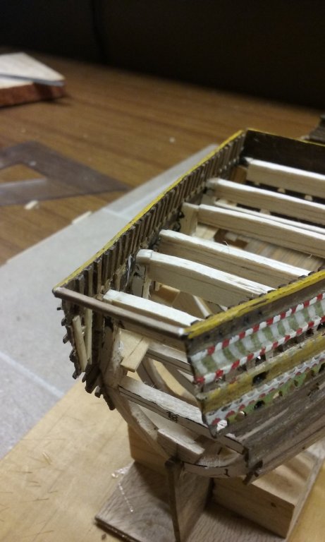
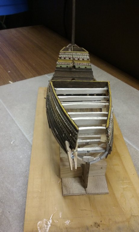
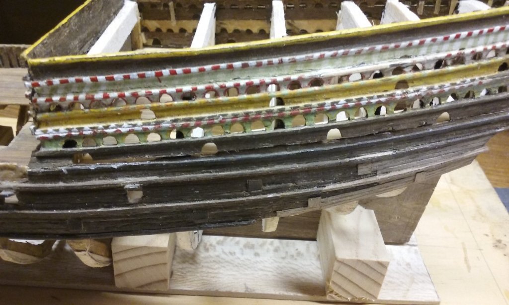
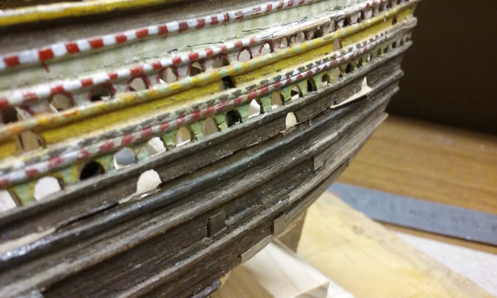
Well, that's fixed, anyway. I've now put the port superstructure back in place and it now all lines up - at least as well as possible - any further discrepancies come from my 17-year old self not making it perfect in the first place. I was hoping to make the after face of the superstructure the same way it would have been back in the day, with the wales and the strakes made and installed individually, using the cardboard template to define the shape. Unfortunately it just didn't work out that way. I ended up having to make it out of a single sheet of wood (got it right on the second attempt), with the wales glued on the outside instead of forming part of the structure. There is now quite a gap between the lower hull and the port superstructure, which I will have to infill with a new strake. Still, it's now starting to look like the kind of stern you see in Bruegel's paintings, which has got to be a good thing . . . Steven

- 740 replies
-
- 11
-
-
- Tudor
- restoration
- (and 4 more)
-
Hi Kikatinalong, I've had a look at the Mamoli kit and it's a rather nice looking ship. While I agree you're taking on a pretty ambitious project, there's no reason you can't make something to be proud of, even though you may find a few things you aren't totally satisfied with on this, your first build. One thing that might help you, as well as the advice above, particularly from pontiachedmark and knightyo, is to look at the planking tutorials on this forum in the section " Building, Framing, Planking and plating a ships hull and deck" - Planking is a particularly fiddly activity and it's good to have an understanding of the technique before you start. Some kits advocate an oversimplified method of planking which doesn't correspond to the reality, but looking at pictures of your kit, that doesn't seem to be the case. And as you're building a carrack, I'd highly recommend Woodrat's excellent build as a reference. What's not included in that is hardly worth knowing. And as several others have suggested, ask LOTS of questions. The people on this forum are invariably helpful and someone will probably have already found an answer to the problem you're faced with. Best wishes with your build, and start a build log to share your triumphs and problems with the rest of us. PS: Where do you live? As you can see, I'm in Ballarat. You might find other members who aren't all that far from you. Steven
-
Well, why not, Rick? Sounds like something worthwhile to do. And who knows you might get back on it and get a lot of enjoyment from it. Steven
- 740 replies
-
- 2
-
-
- Tudor
- restoration
- (and 4 more)
-
However, whether the Mayflower was painted is another question. She was a fairly small merchant vessel, not a top of the line navy ship. She might have been painted, but as we know almost nothing about her except her approximate size, that she was hired by a bunch of people who weren't all that well off and that she was fairly old in 1620, your guess is as good as mine. There was a reconstruction built of Mayflower in 1957, which was sailed across the Atlantic and is still in Plimouth Plantation. She has a bit of decorative paintwork - do a google image search for Mayflower replica and you'll see her. Apparently a new reconstruction is being built at the moment, but I couldn't find any pictures of her.
-
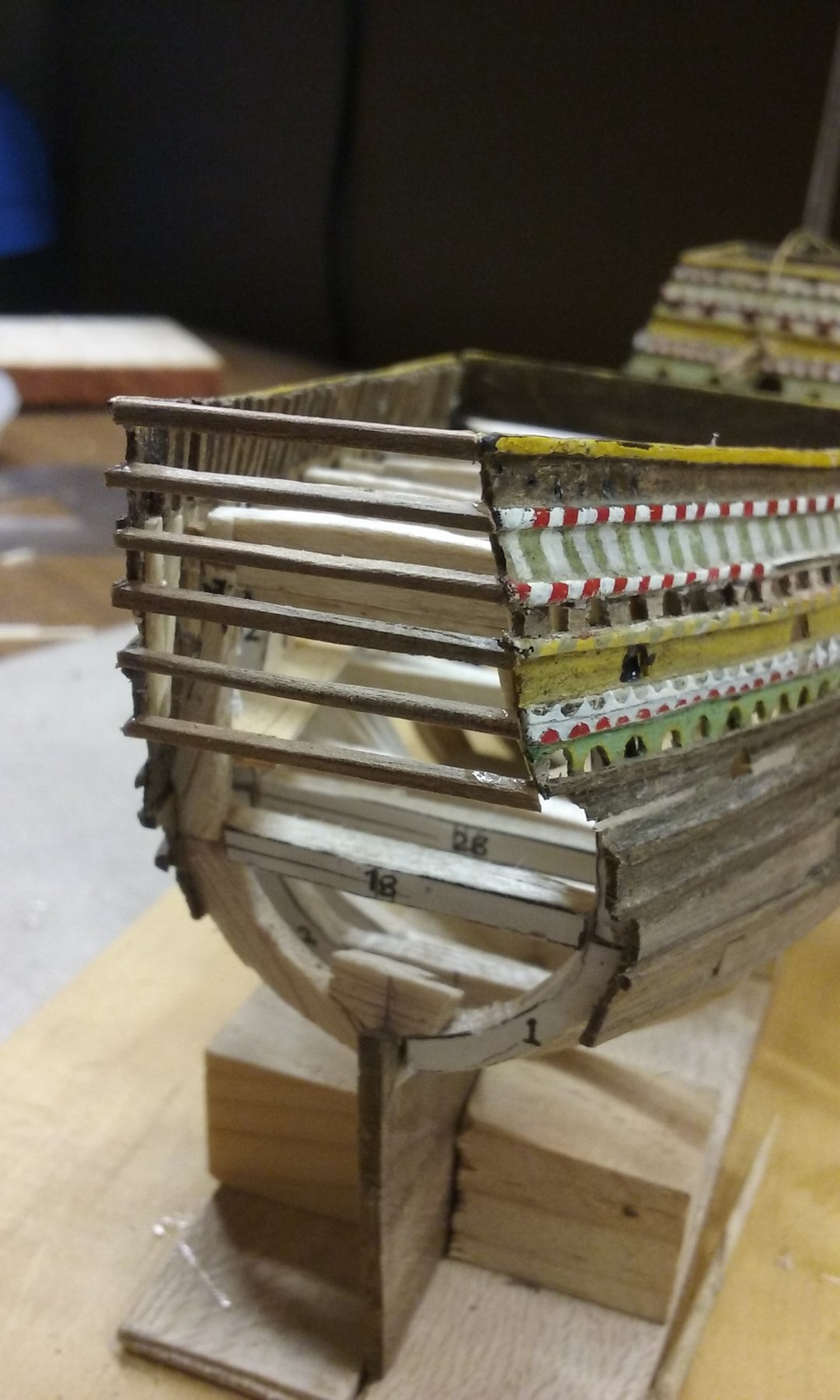
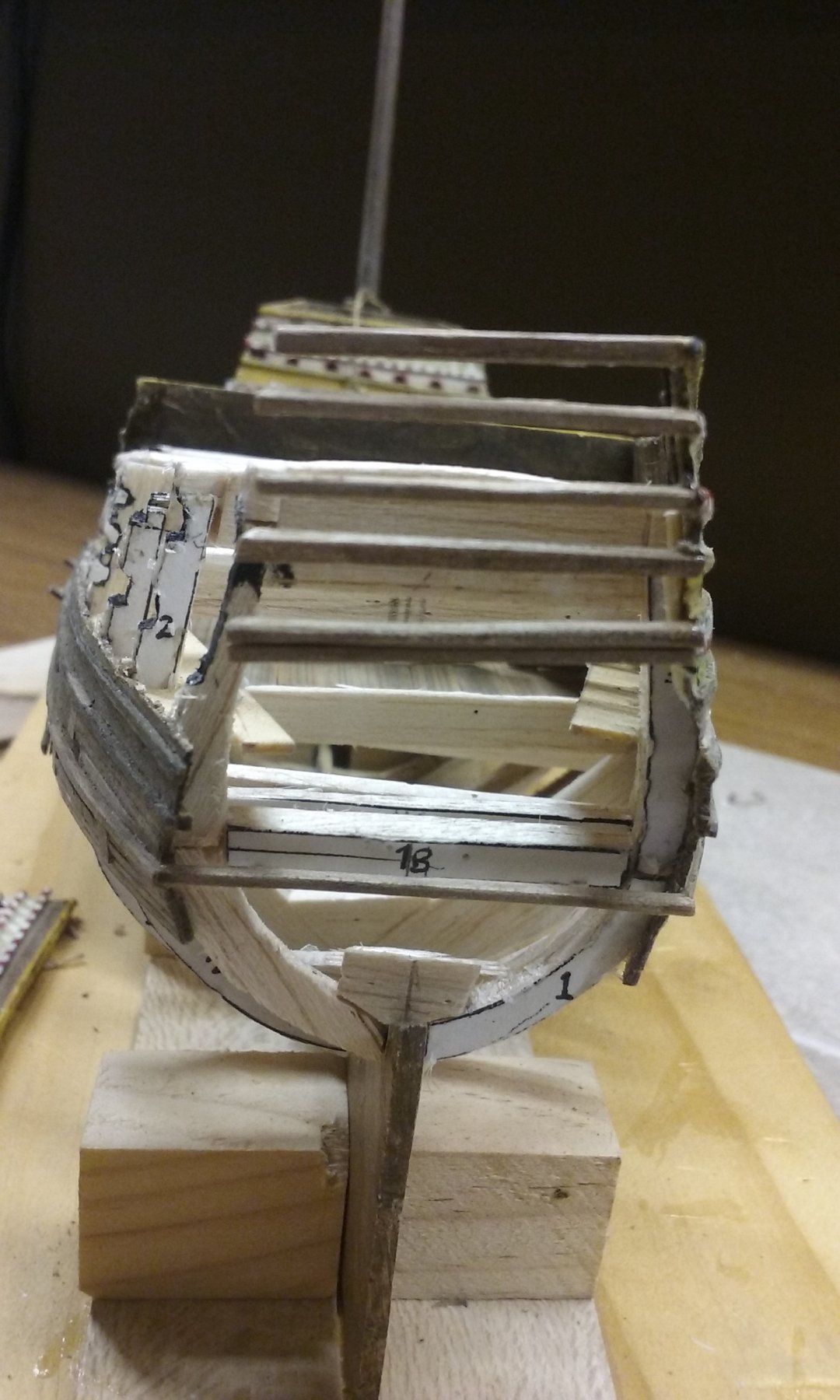
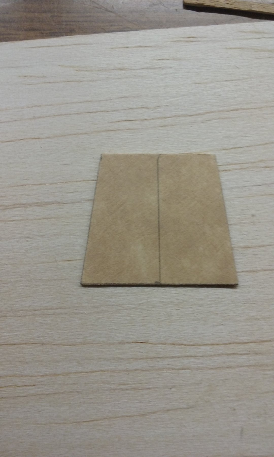
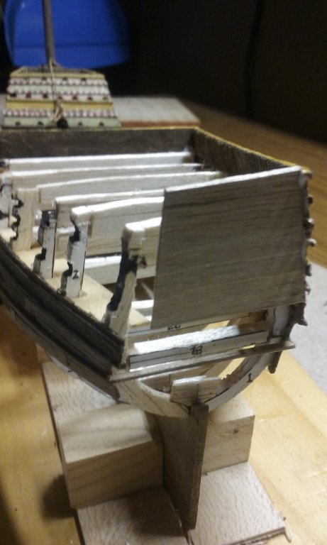
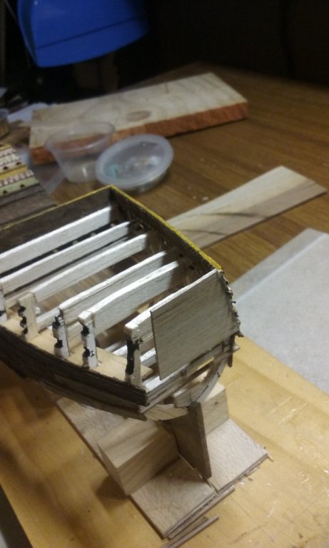
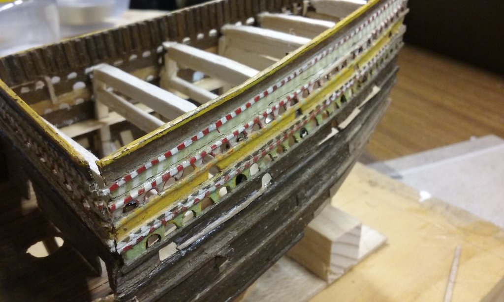
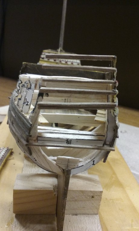
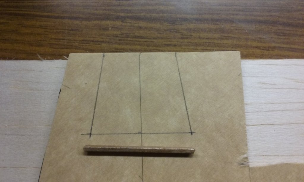
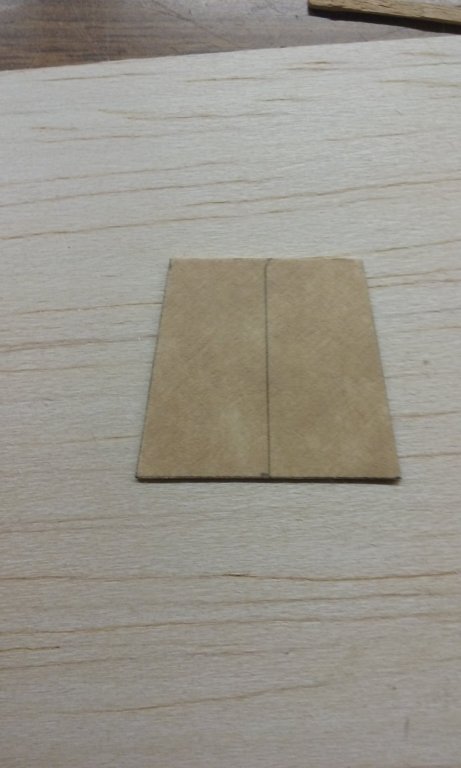
Well, I started adding more slivers between the port superstructure and the lower hull, and cutting them back flush with the planking. Then an AAAAARGGGHHH moment, I'm afraid. I've discovered that I'd got the position and alignment of the port superstructure wrong. You can see it on the following photos. When I started putting in cross-pieces at the stern I realised the starboard side was higher than the port, so the crosspieces weren't square. You can see the difference in angle between the top crosspieces and the one at the bottom, which is the only one that's correct. I could have left it as it was - "she'll be right" - but I know it would have sneered at me from then on, and I'd have cursed myself for not fixing it when I could have. So I've removed it again (thank heaven for isopropanol) so I can fix it properly. I've made a cardboard template which will be used to get the shape of the after end of the aftercastle right. I'll be able to re-use all the bits, but it's rather annoying. In retrospect, I don't think there was any easy way to avoid this problem. There were too many variables - I just had to try it and see how it worked. But perhaps I could have thought it out better in advance instead of charging in like a bull at a gate. Sigh. Steven

- 740 replies
-
- 10
-
-
- Tudor
- restoration
- (and 4 more)
-
Superb as usual, Xavier! The quality of your work is consistently excellent and inspirational. Steven
-
Hi Phil, You're doing a good job with your cog. You'll find all kinds of models on this forum, including even some 3D digital ones for gaming (plus an embroidered portrait of HMS Agamemnon in cross-stitch), so don't worry about your balsa wood one. It's all about the enjoyment of the build, not about impressing people - though some of the builds on this forum leave me slack-jawed with awe. I love mediaeval and renaissance ships, and the cog is a particularly attractive one. I think for the purpose you're building it for, your cog is totally ok, and your construction method is quite adequate for the job the ship is to do. A lot of ship models (including my own) fudge the bits that are below decks. "If you can't see it, it's not there". You might like to get some more information on cogs (if you don't have it already) from https://en.wikipedia.org/wiki/Bremen_cog and https://artsandculture.google.com/exhibit/owKSqVwIBfJGJw . Though many cogs had rectangular forecastles, the Bremen cog doesn't seem to have had one (though it seems to have been under construction when it sank - maybe they hadn't got around to adding the forecastle yet?). I think Luponero's idea (he's writing in Italian and Google is translating into English for him) is to cut a small hole in the stern, and add a rudder with a fake tiller that just goes through the hole and stops. My own opinion is that you should add an aftercastle like on the Bremen cog. At this time the castles weren't integral with the hull- they were sort of just "plonked" onto ships as an afterthought. If you compare your model with the pictures of the Bremen cog, and particularly the model on the second link above, you can see that the sternpost that supports the rudder goes up on an angle, following the angle of the hull, and the rudder is swung from that. I think you should trim the sternpost to be like that and then add a rudder (which is what I think you had in mind in your post #5 above) , and the rudder comes up through the aftercastle, the tiller can be above the deck of the aftercastle, which is what I believe you are after. I hope that makes sense. Oh, by the way your Viking boat at the top would be better called a faering (four-oared boat). A knarr was a fairly large merchant/cargo ship. Keep up the good work, and if by any chance you do go over to the Dark Side and get into serious modelling, you'll find this community very friendly and helpful. Steven
-
Pat, I'm pretty sure the Hamble River remains are of Henry V's (the Agincourt guy) Grace Dieu. My model is of Henry VIII's (the guy with VIII wives) Henry Grace a Dieu. Different ships with similar names, over 100 years apart. Having said that, I think the Grace Dieu is fascinating as well. She was enormous for the time; if I remember correctly she was about the size of the Victory - in comparison with other ships of the era she was sort of like the Great Eastern compared with the Sirius. There was (and still may be) a set of lines for the surviving hull on the Net. I think this might have been connected with the Time Team investigation of maybe a decade ago done by echo-location, I think. As usual, only below the waterline has survived, and you could only get a small picture taken from an angle which was all but useless. I've meant to contact whoever's in charge to get a proper copy of them but never got around to it. Steven
- 740 replies
-
- 6
-
-

-
- Tudor
- restoration
- (and 4 more)
-
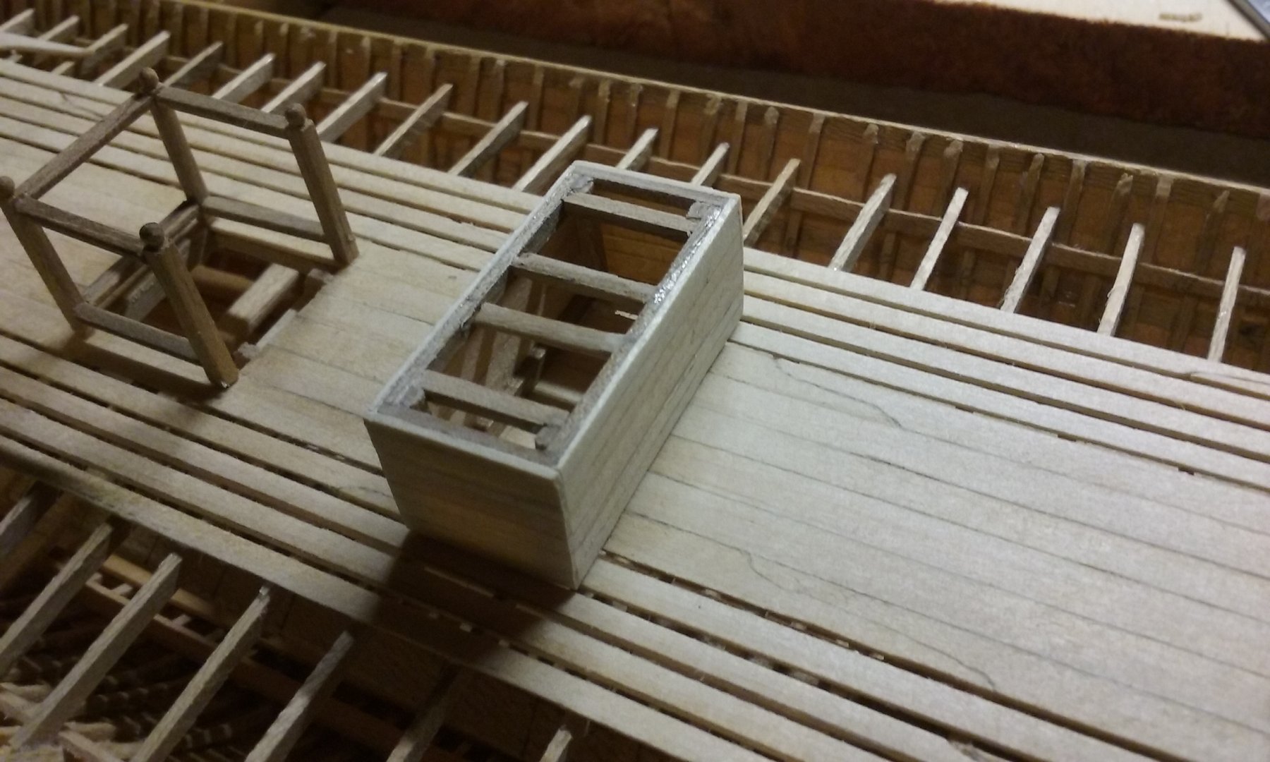
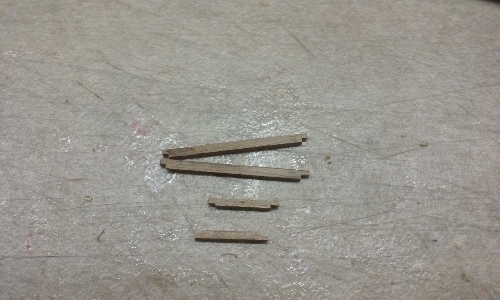
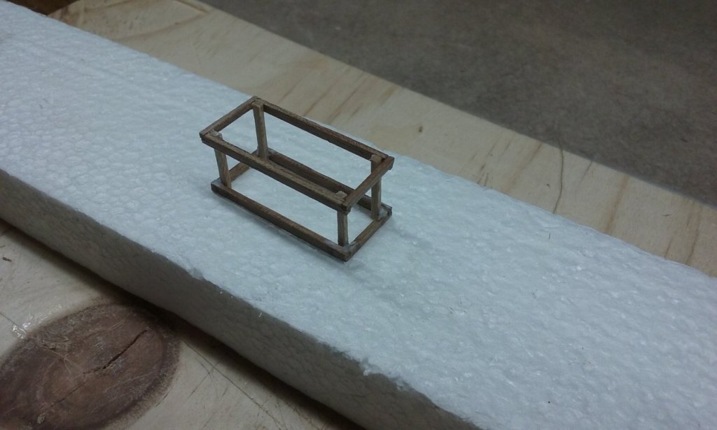
Thanks everybody for the likes. Dick, the Serce Limani "glass wreck" of c. 1025 had vestiges of a chain pump according to one of the published papers, and I believe (can't remember where from - might be the same paper) that the Romans had them, and as the Byzantines were continuing the Roman tradition the presence of one in the 11th century seems logical. I have thought long and hard about whether to include a chain pump as the evidence is a little thin on the ground, but I ended up deciding to go for it. And here are some progress photos for the pump: The "box" is glued in place, but the wheel covers are currently just dry fitted. I still have to sort out what I'm going to do about the axles and the crank handles. I also have to cut holes in the ends of the box for the lands. Steven

-
Beautifully detailed, Fabio. It's getting to be a very impressive model. Steven
- 197 replies
-
- 3
-
-
- santa maria
- carrack
- (and 1 more)
-
Beautiful carving work, Fabio - both the arches and columns and the Madonna and Child. I take my hat off to you, sir. By the way, quite a few carracks are shown in contemporary pictures with a dragon-head as a figurehead. And one of these has even been found on a Scandinavian wreck of the time. However, the very great majority of contemporary pictures of carracks show no figurehead at all. So you don't really need to have one on your own model. Steven
- 197 replies
-
- 4
-
-
- santa maria
- carrack
- (and 1 more)
-
Very ingenious and nicely carried out, Dick. Steven
- 263 replies
-
- 3
-
-
- nave tonda
- round ship
- (and 2 more)
-
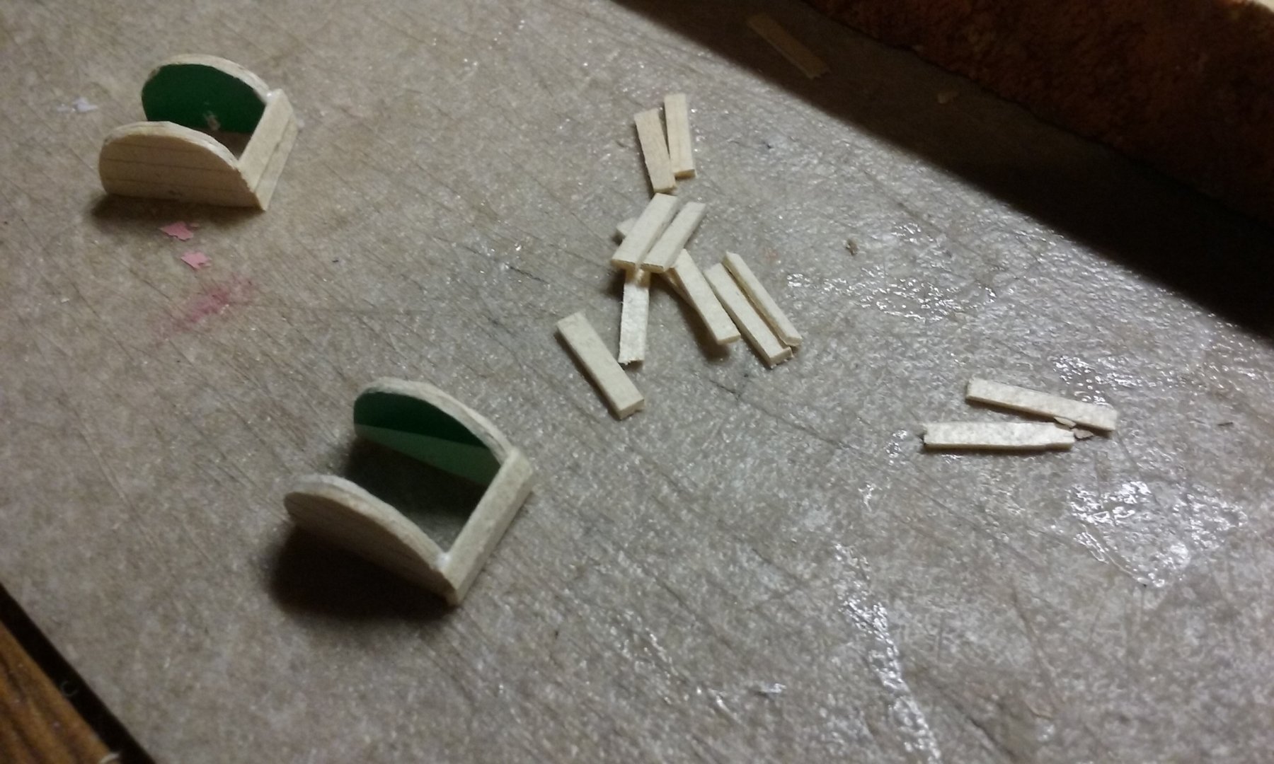
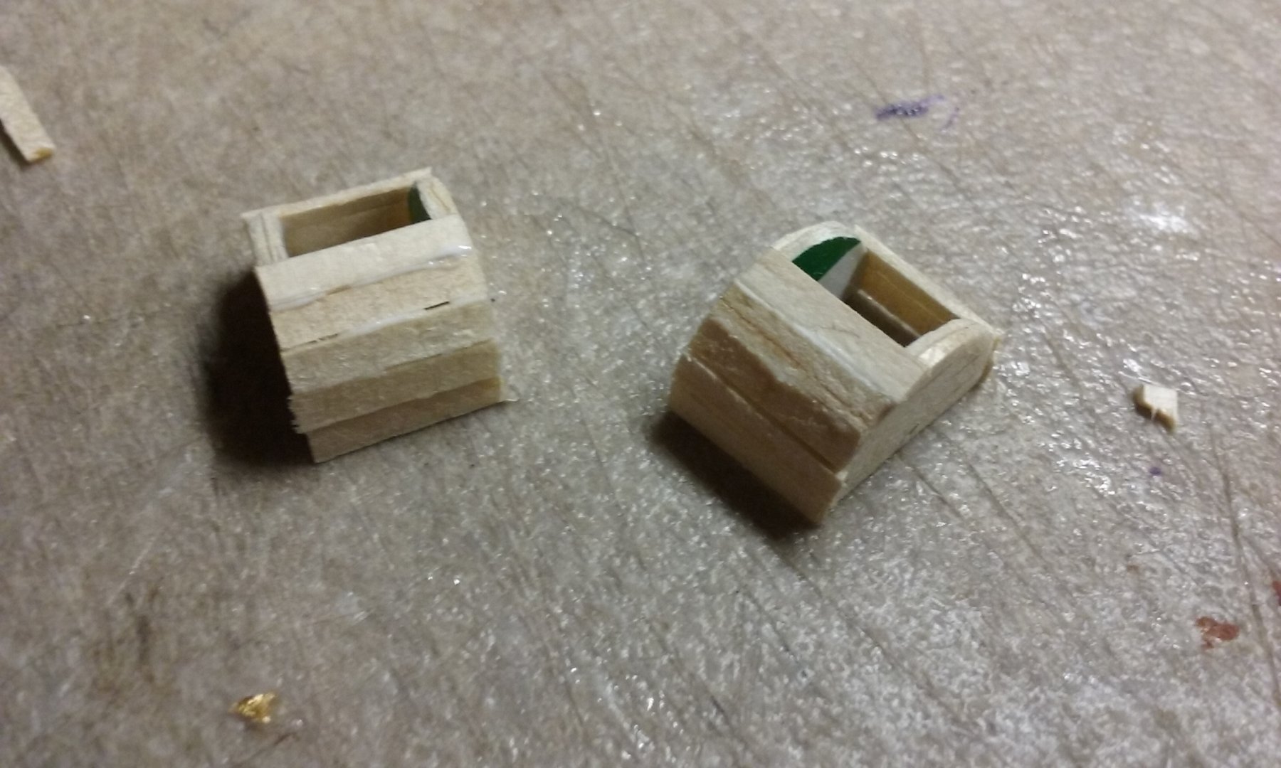
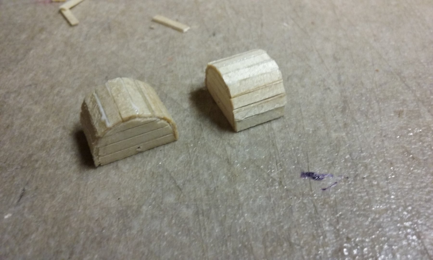
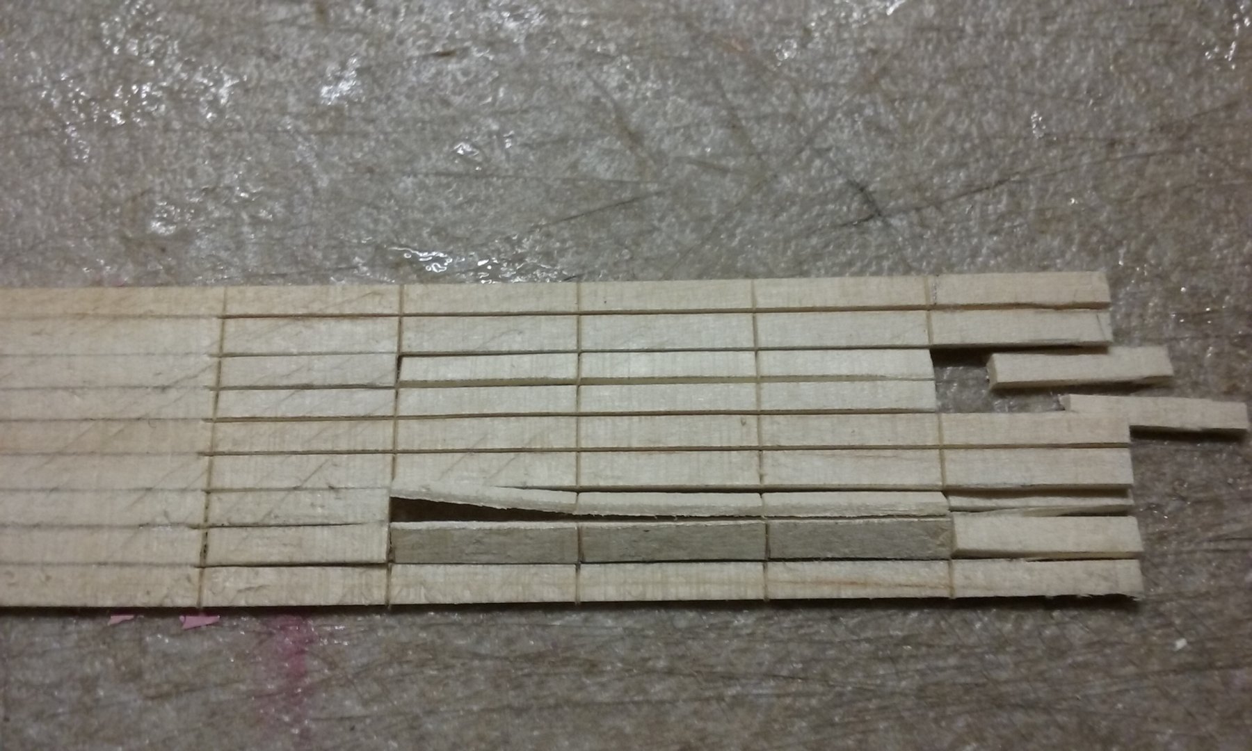
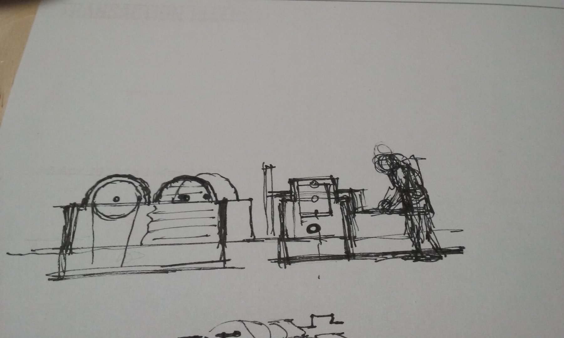
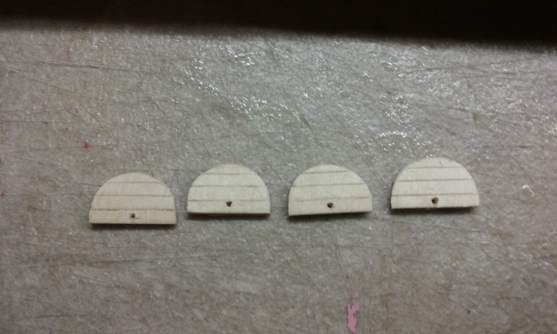
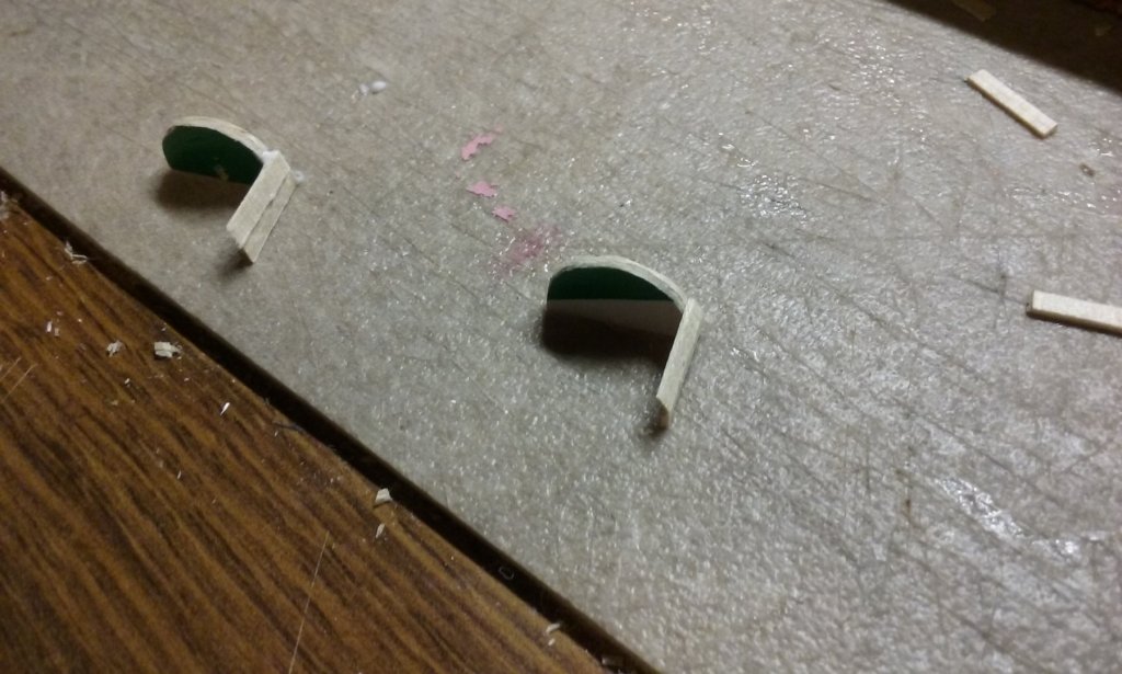
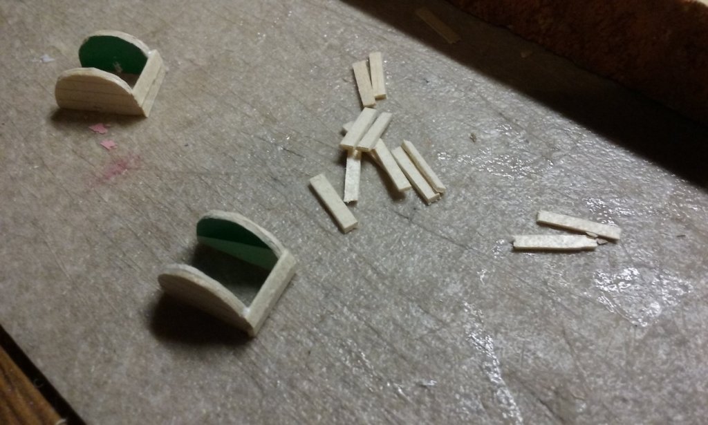
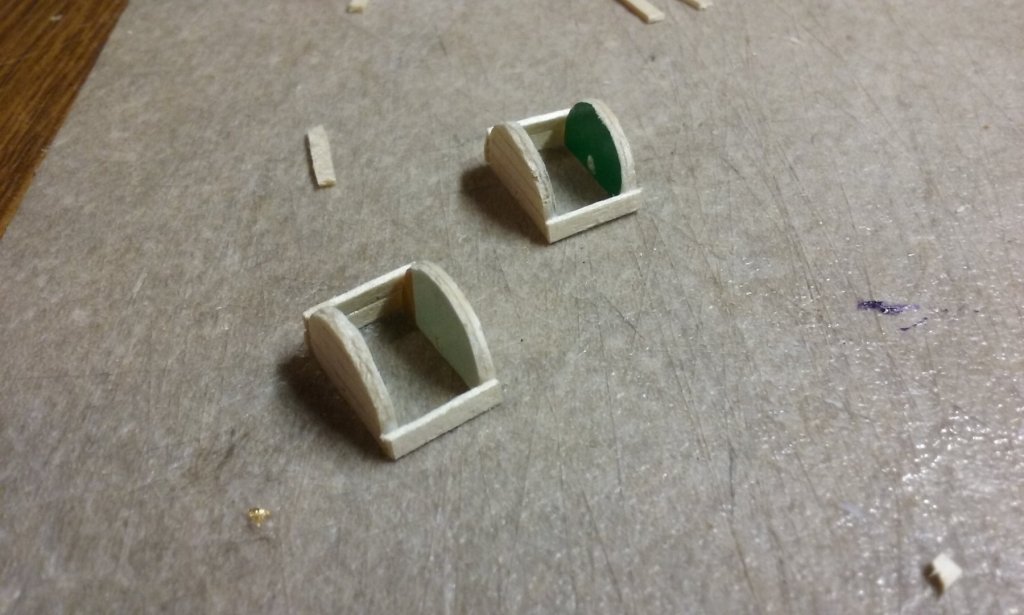
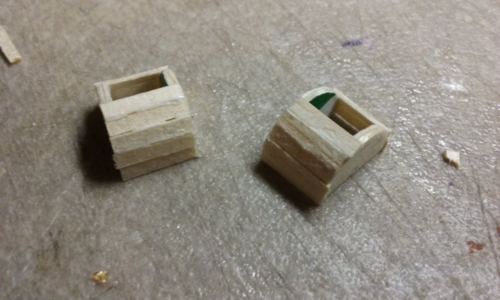
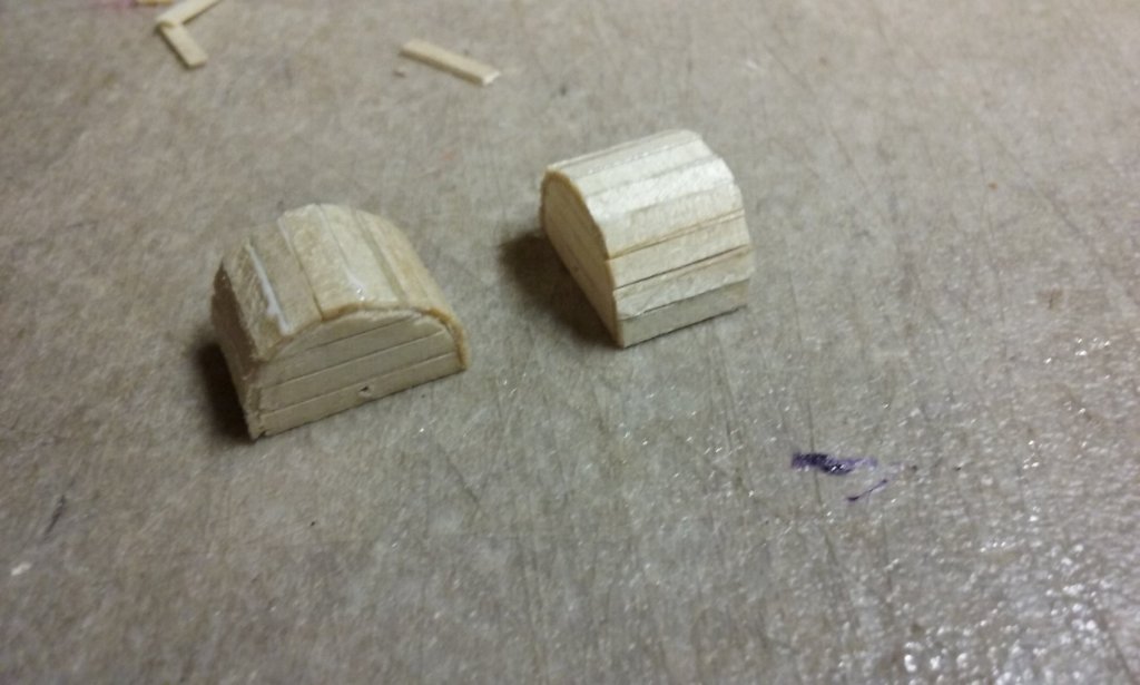
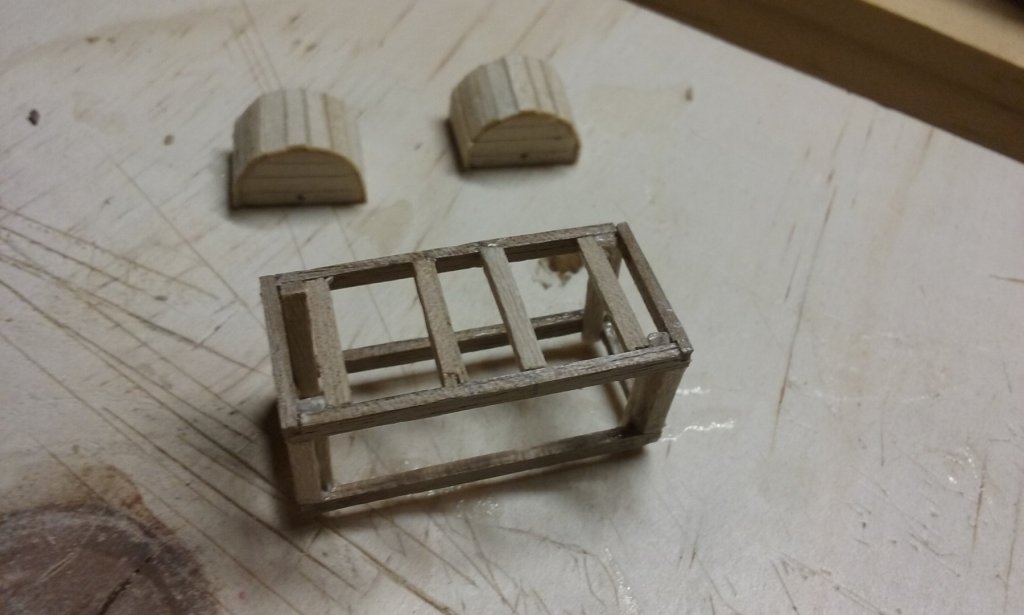
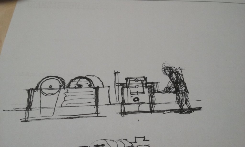
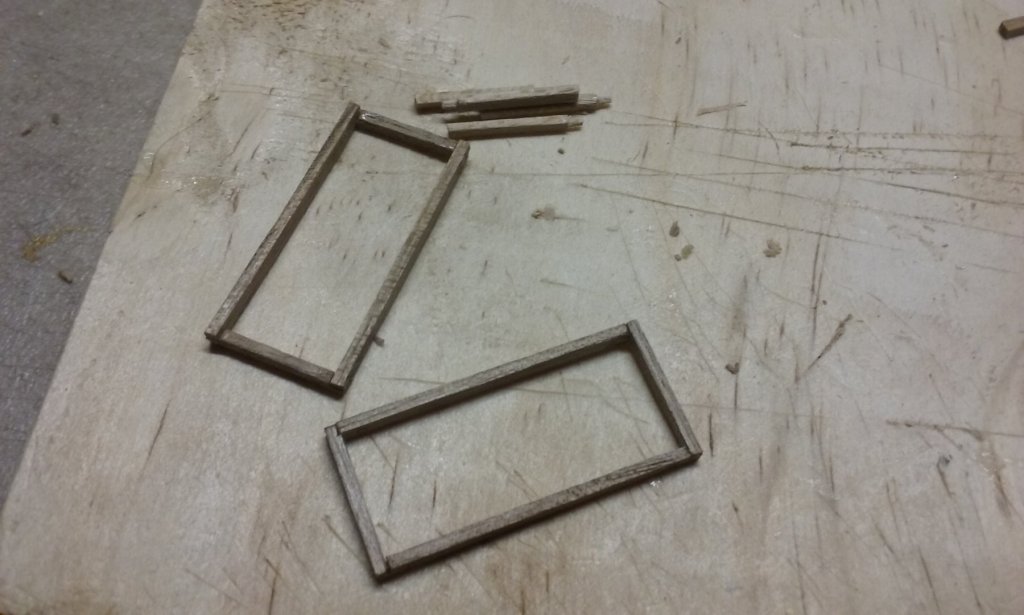
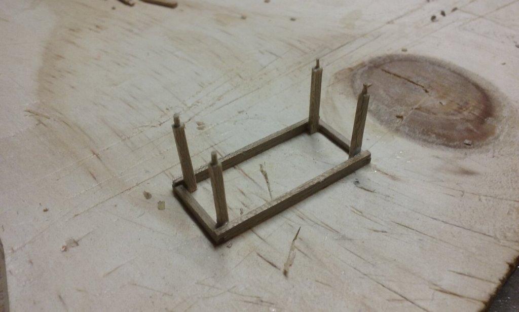
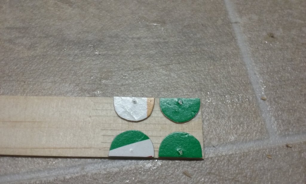
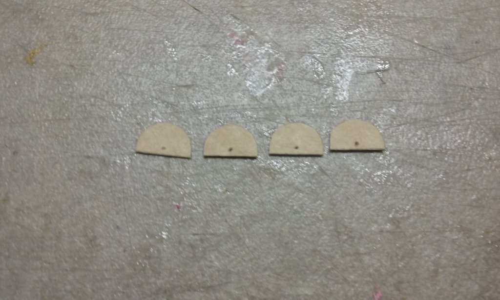
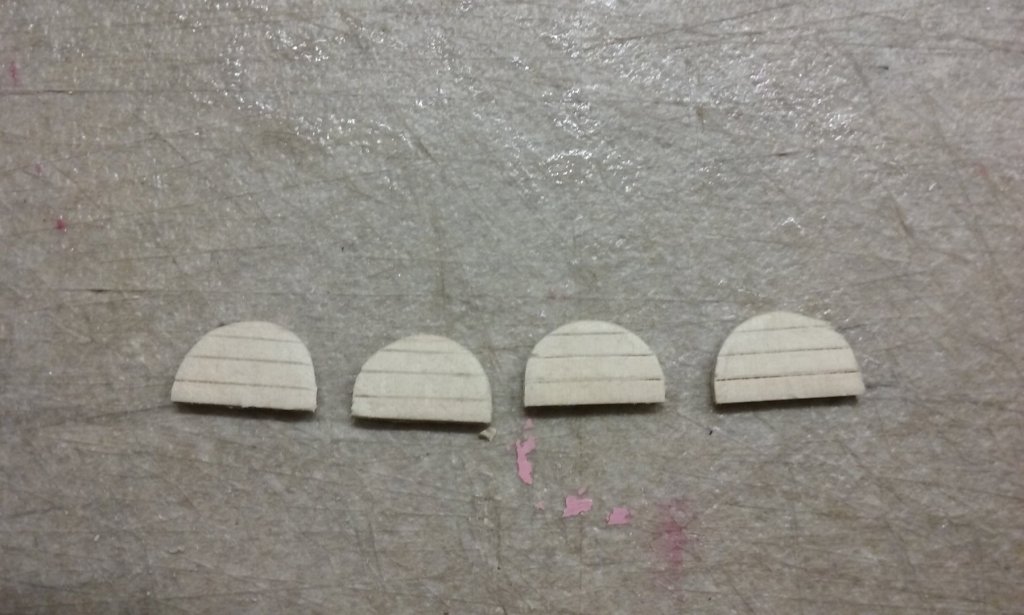
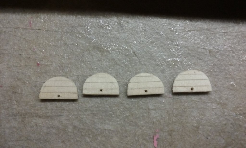
Working on the chain pump. Here's the sketch I did (to the same scale as the model) to work out the sizes: Starting on the frame - top of the "box" And the bottom frame, plus the sides: Top frame attached to the side pieces - note the locating "pins" at the ends of the side pieces, to insert into the deck. I put the pins into a piece of styrene foam to simulate the deck so the bottom frame could be at the right level. Cardboard semicircles to act as backing for the planking on the covers for the drive wheels: Glued to the sheet of wood with planks sliced into it. The planked side pieces cut out. And the holes for the axles added. More to come. Steven

-
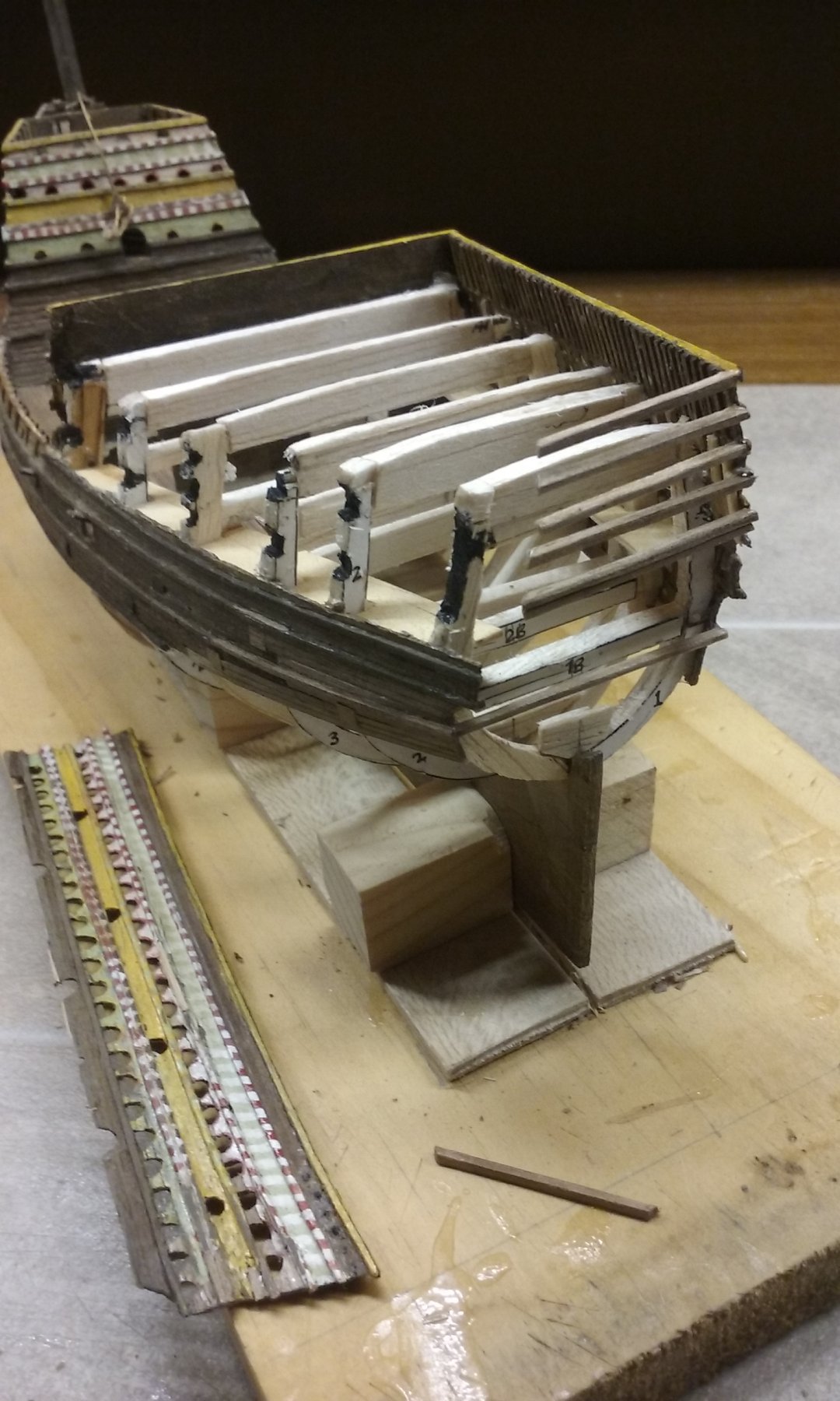
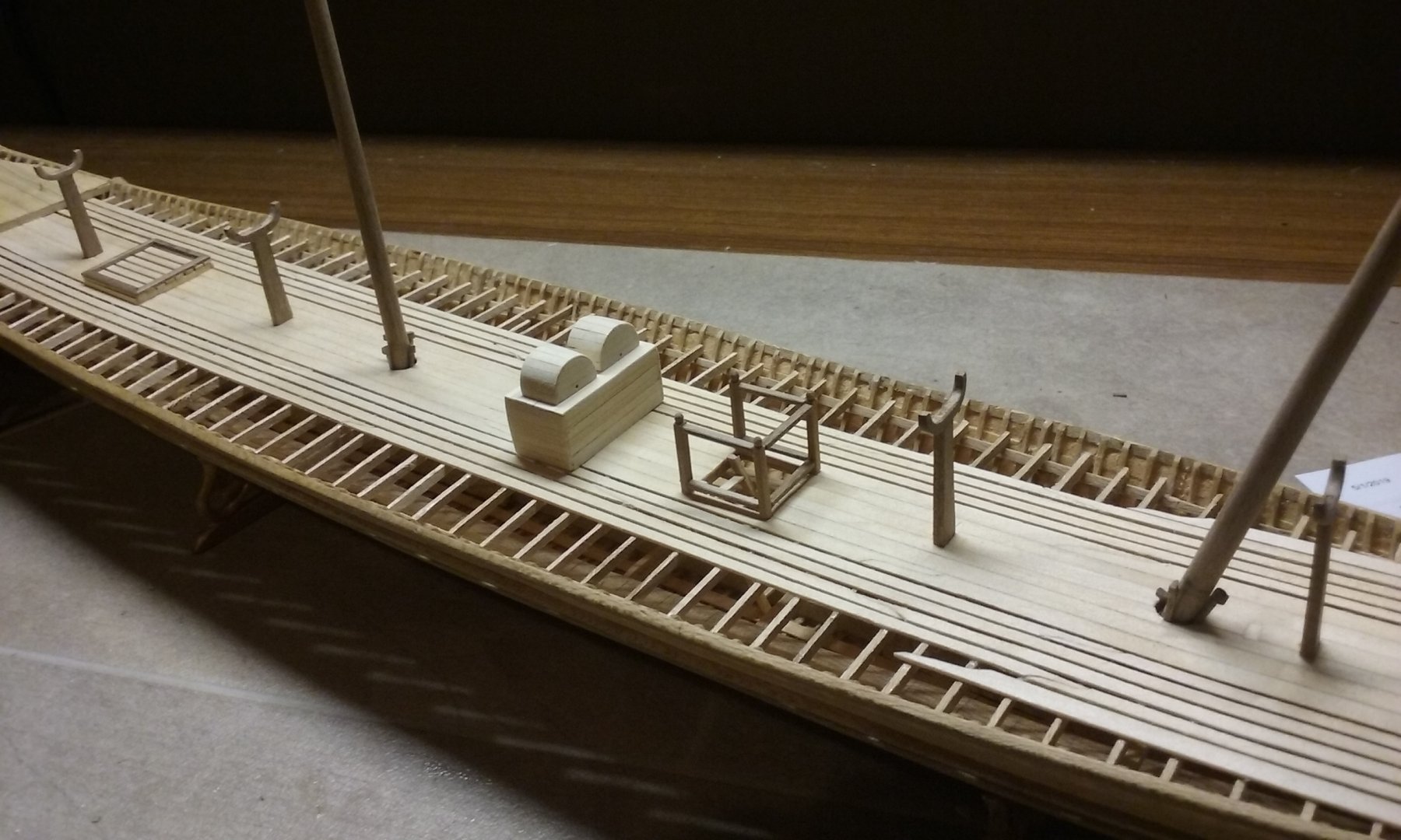
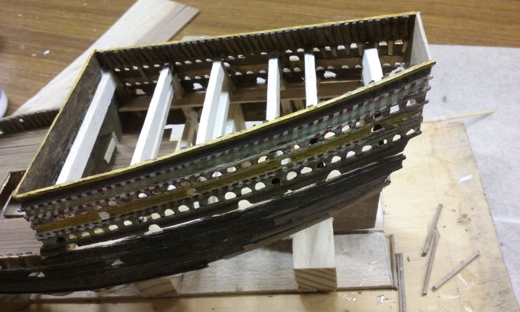
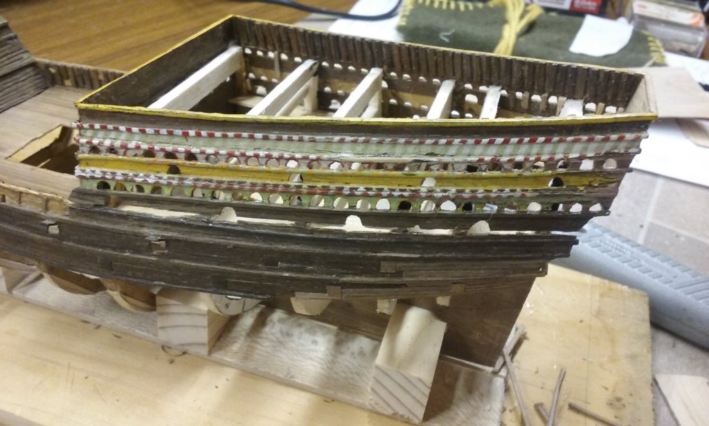
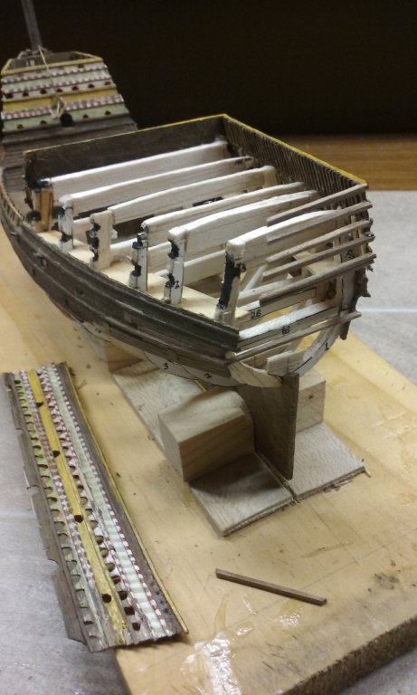
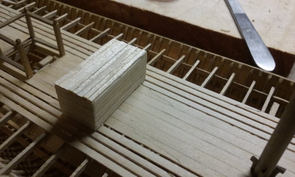
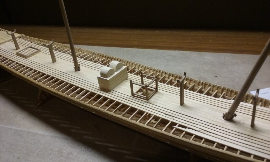
I've added the superstructure for the port side of the aftercastle. I had to sit with my thumb on the forward end till the glue dried - there was no other way to clamp it in position. Because the stern is narrower than on the original model, the complex curves of the bottom of the superstructure and the top of the main hull no longer lined up with each other - there's a long narrow gap between them. So I've started putting a sliver of wood in the gap. I didn't want to make any more cannons than I had to, so I've also added port lids to all the gunports except those at the "well deck", where the guns are visible anyway. Steven


- 740 replies
-
- 14
-
-
- Tudor
- restoration
- (and 4 more)
-
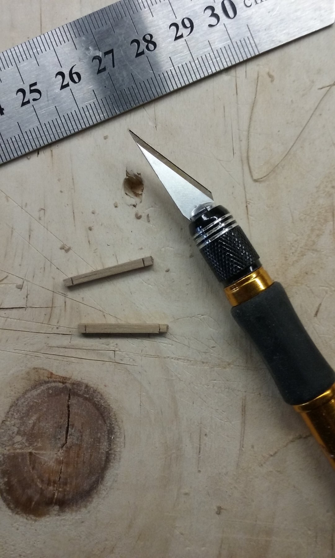
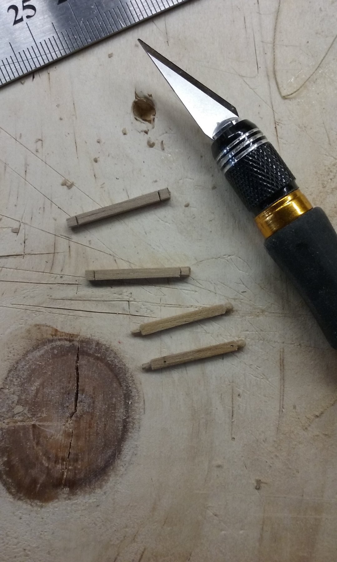
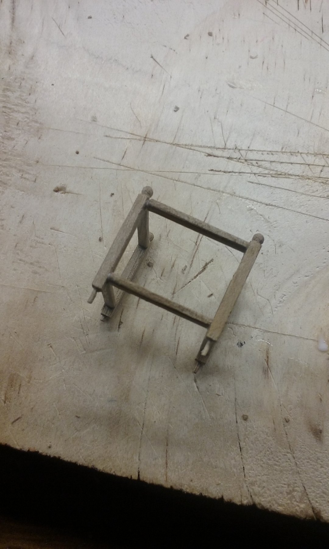
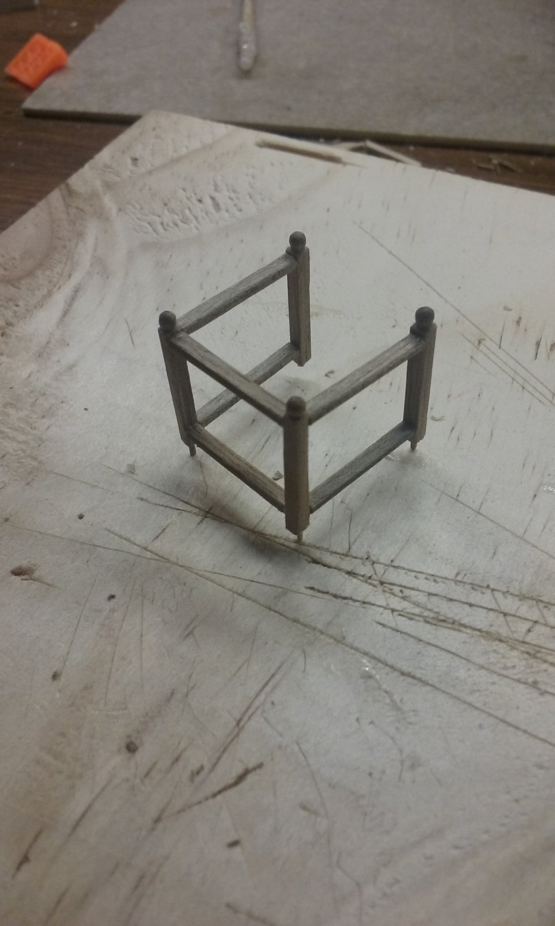
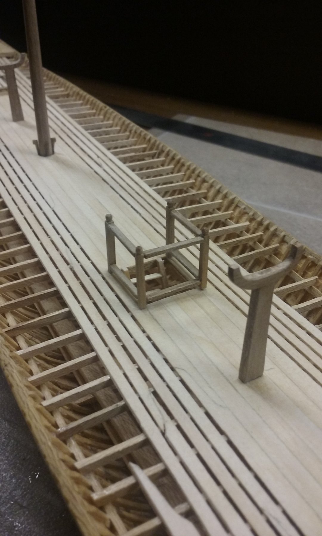
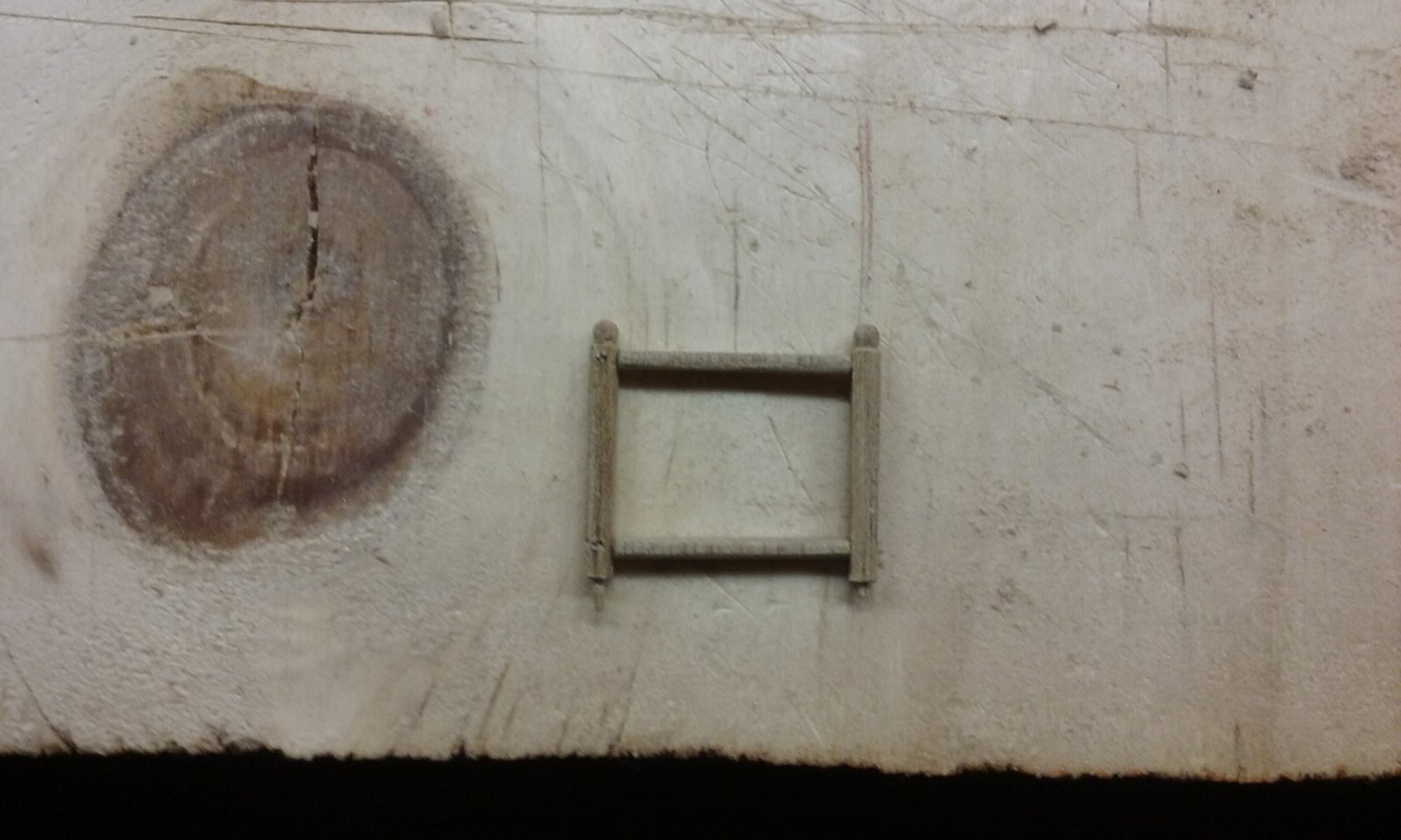
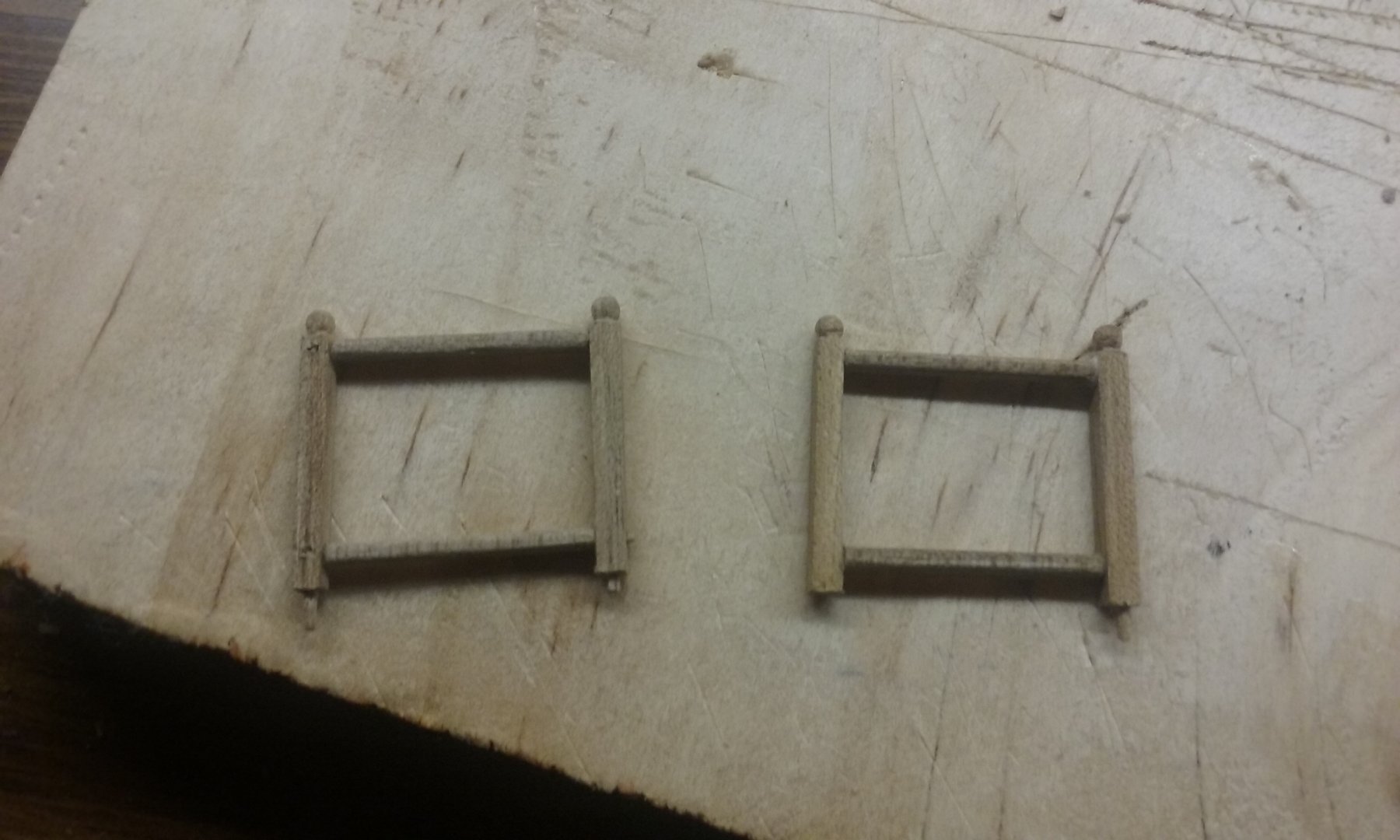
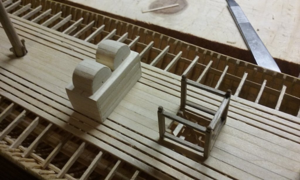
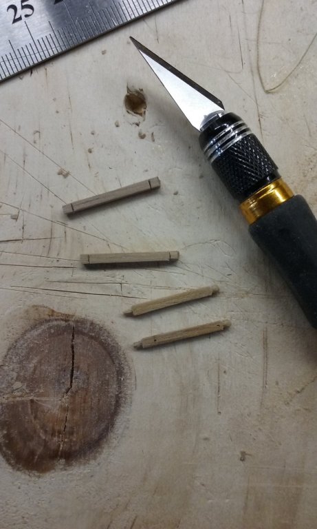
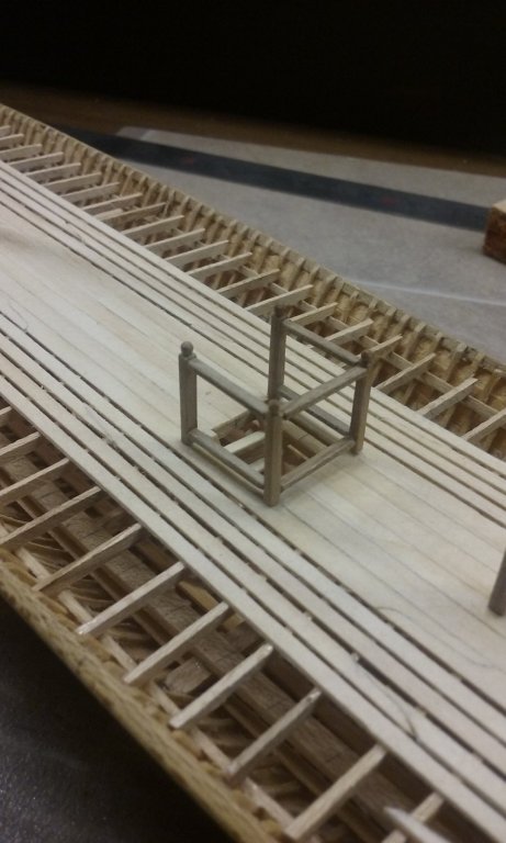
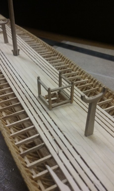
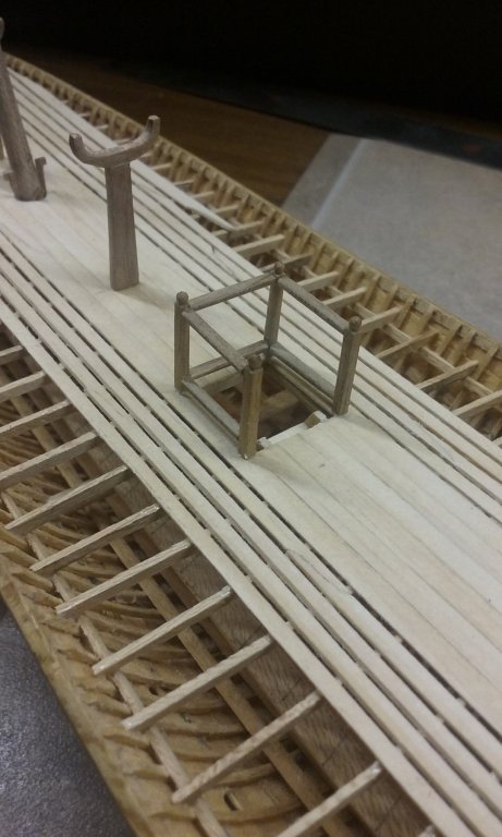
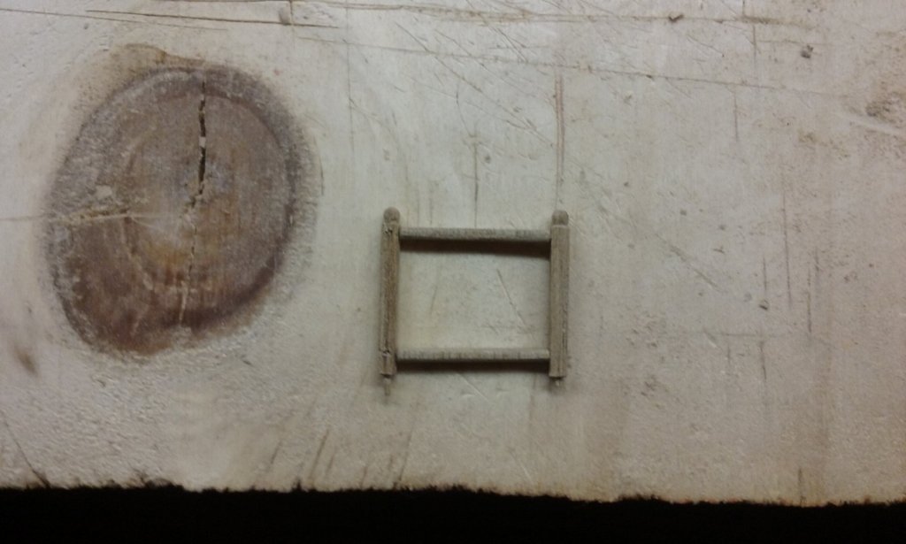
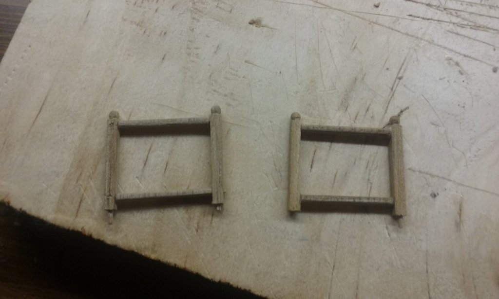
Here is the railing for the ladder to belowdecks. I did one version, wasn't happy with it,and this is version 2. The uprights: Side rails in place: Unfortunately, one of the wooden locating pins broke off the bottom of a post, (see picture above) and I had to drill a hole in the end and put a new one in. Assembled: In place on the deck: Steven


-
Napolean Prisoner of War Models
Louie da fly replied to apprentice's topic in Nautical/Naval History
There are a couple of Napoleonic bone models at the Maritime Museum in Southampton, a 14th century stone barn re-purposed, and with a Titanic exhibit on the upper floor - at least that's the way it was when my wife and I visited in 2009. Steven -
Thanks for the likes, and thanks Don for posting that picture. It seems to me that these things have been around doing the same job since at least the 5th century AD and right up to the present, so an 18th century example (which appears to be doing exactly the same thing as on the modern video) is right on the money. Interesting that there are two of them. One appears to be near the top of the halyard - is the other one also on the halyard, at the bottom? Steven
-
Aaaaaaarghh! The memories!!! Seriously, though - that's exactly what they are. Steven