Louie da fly
-
Posts
7,990 -
Joined
-
Last visited
Content Type
Profiles
Forums
Gallery
Events
Everything posted by Louie da fly
-
 Looks like you've got the weak spot pretty much sorted. Well done. Looking forward to further progress. Steven
 -
Kris, the presence of shields on the Oseberg ship i news to me. I'd never heard of that before. A rail for shields is called a pavesade. And yes, the gunwale got that name in the 15th century when the only guns in use were relatively light and were placed on the top wale. As they got heavier, to keep the ship stable they had to be placed lower down but the name continued to be used. Of course I found the same applied to my dromon, from well before the invention of guns - if you don't call it a gunwale, what do you call it? Steven
-
The best and most informative site I know of for Viking shields is http://members.ozemail.com.au/~chrisandpeter/shield/shield.html - Chris and Peter are friends of mine from way back when I was a re-enactor. On the other hand, there were no shields found on the Oseberg ship, so if you don't want to add them . . . Kriswood, interesting about the treenails. I didn't know about that. Steven
-
Unless I'm much mistaken, Viking ships didn't use treenails - they had iron nails "rivetted" over at both ends.
-
Looking good, Jo. Steven
-
And here are the completed barrels. The upper group are the first ones I did. I later discovered I'd got my arithmetic wrong and they should have been longer, as are the ones below. I also didn't add magazines to them, but as only the ends of the barrels will be visible i decided just to forge ahead - any major differences will be hidden within the hull. Note - I inadvertently cut the magazine off one of these, but I figure I can just put it on the carriage behind the barrel and it should be fine. And I've cleaned up the "cast bronze" barrel I made back when I was 17, and I'll be casting a group of them which will be visible in the waist. Plus one I turned on the electric drill for the gunports where only the end of the barrel will be visible. I think it's close enough to pass muster . . . Steven


- 740 replies
-
- 8
-

-
- Tudor
- restoration
- (and 4 more)
-
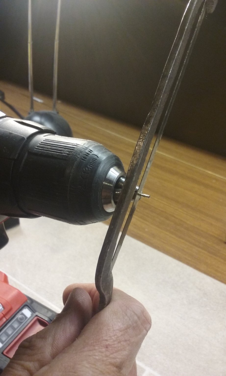
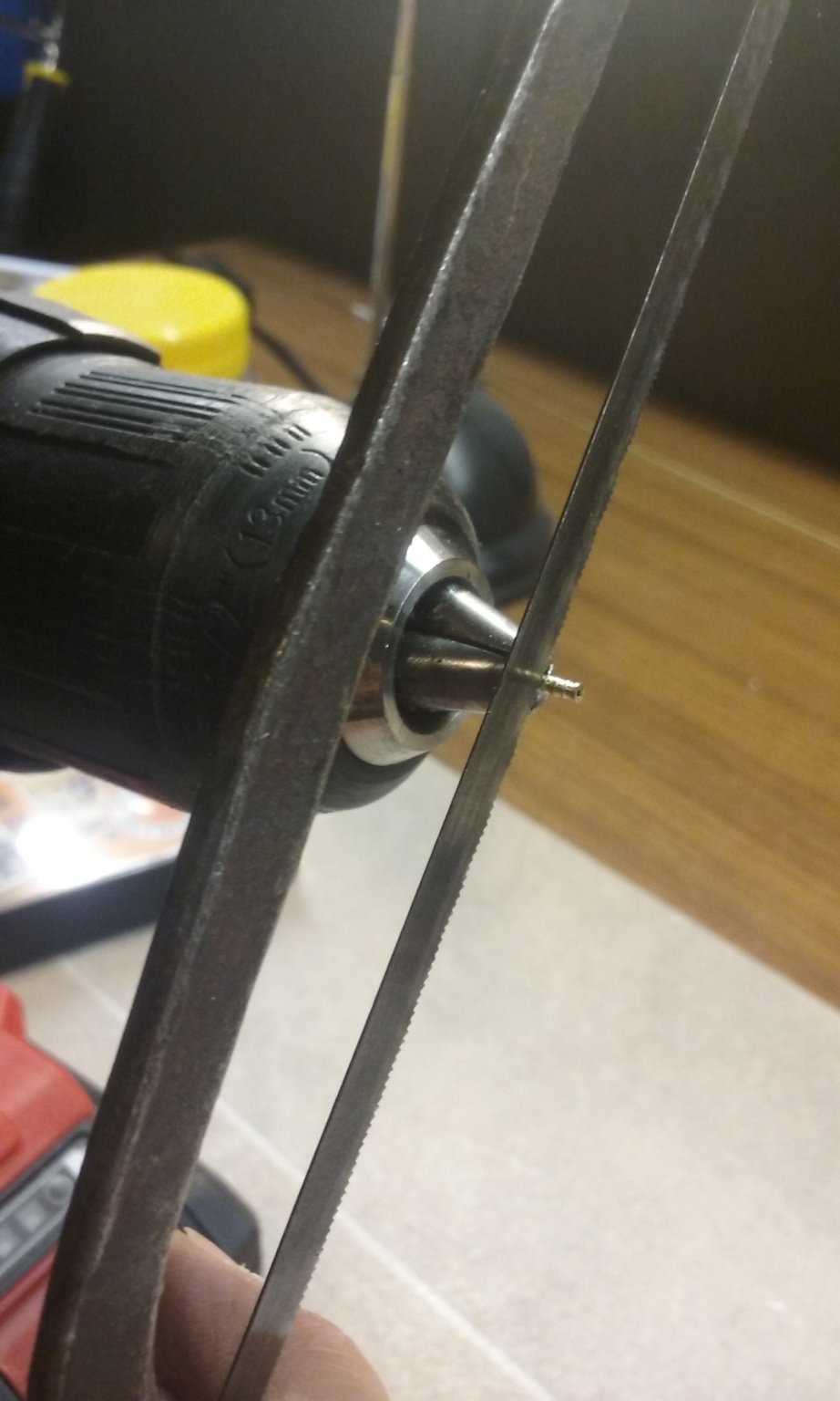
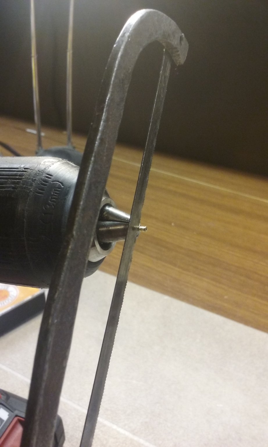
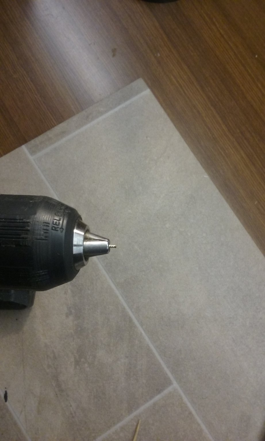
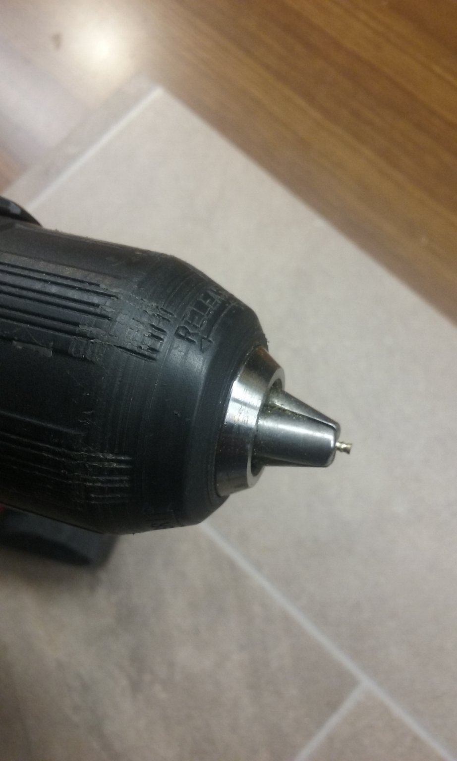
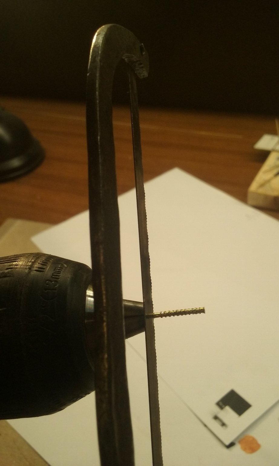
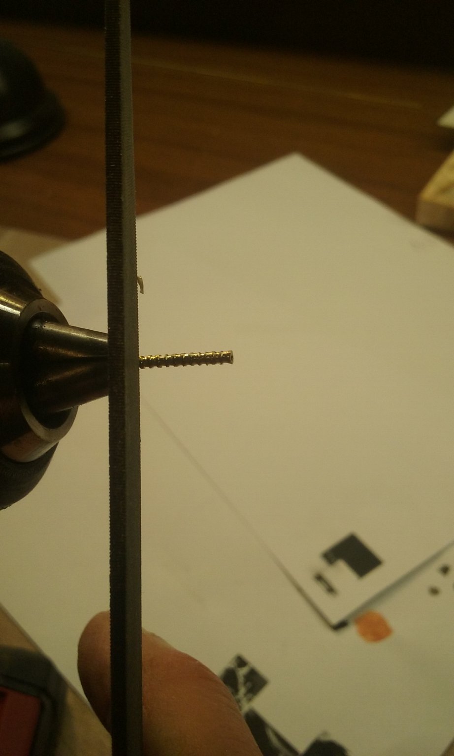
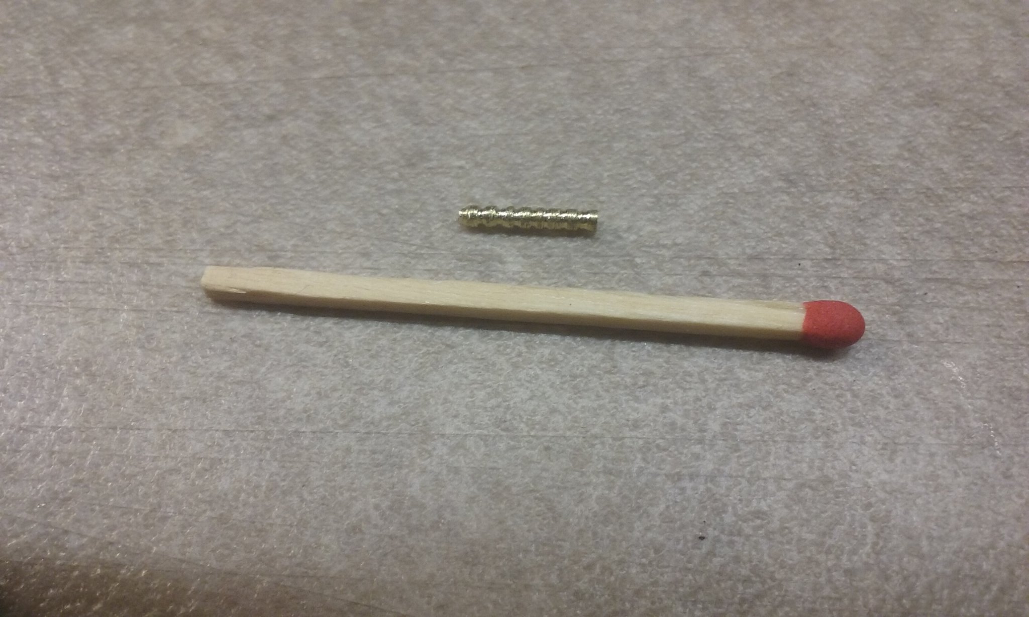
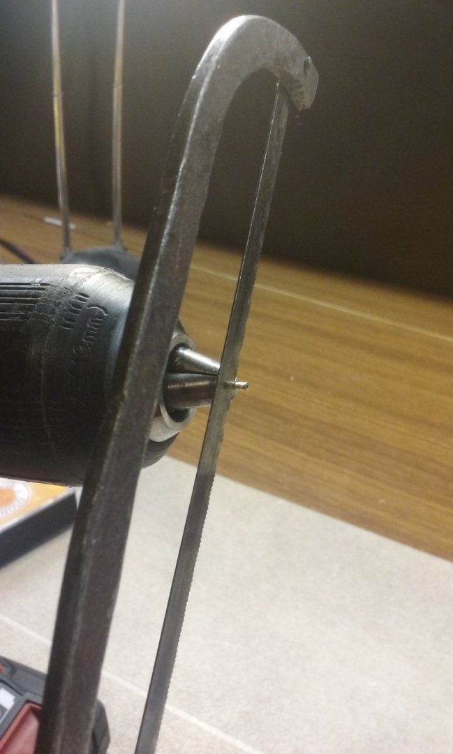
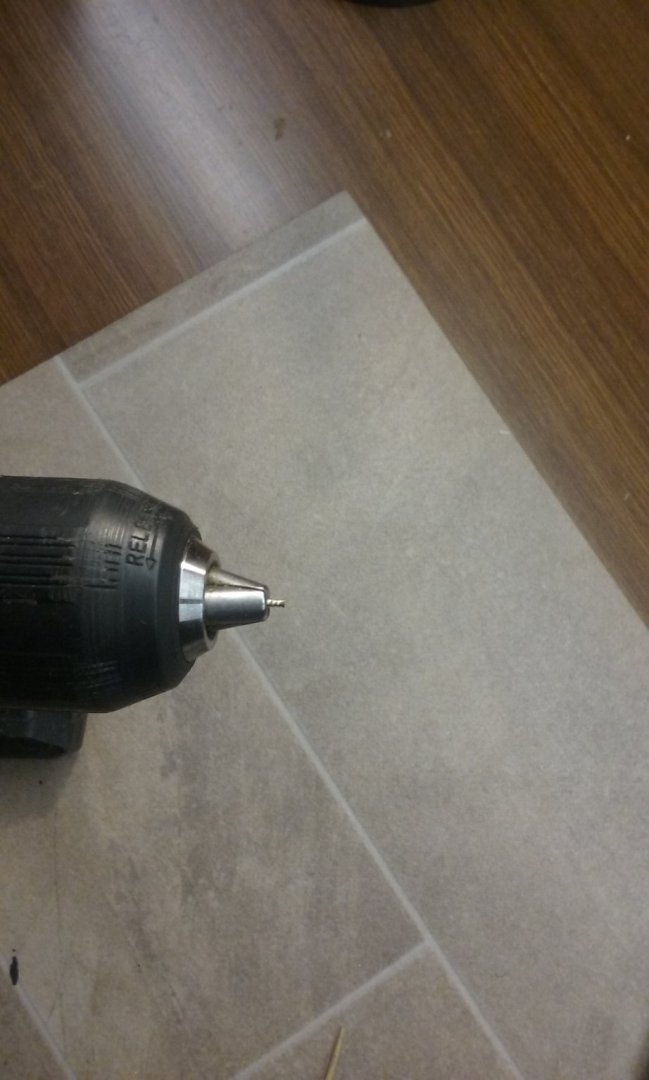
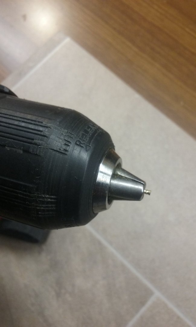
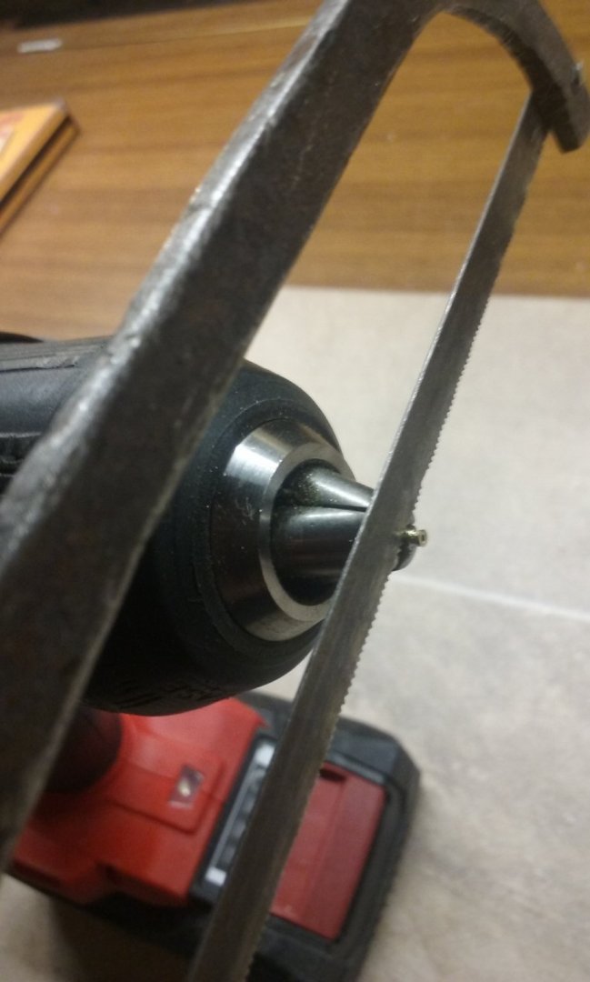
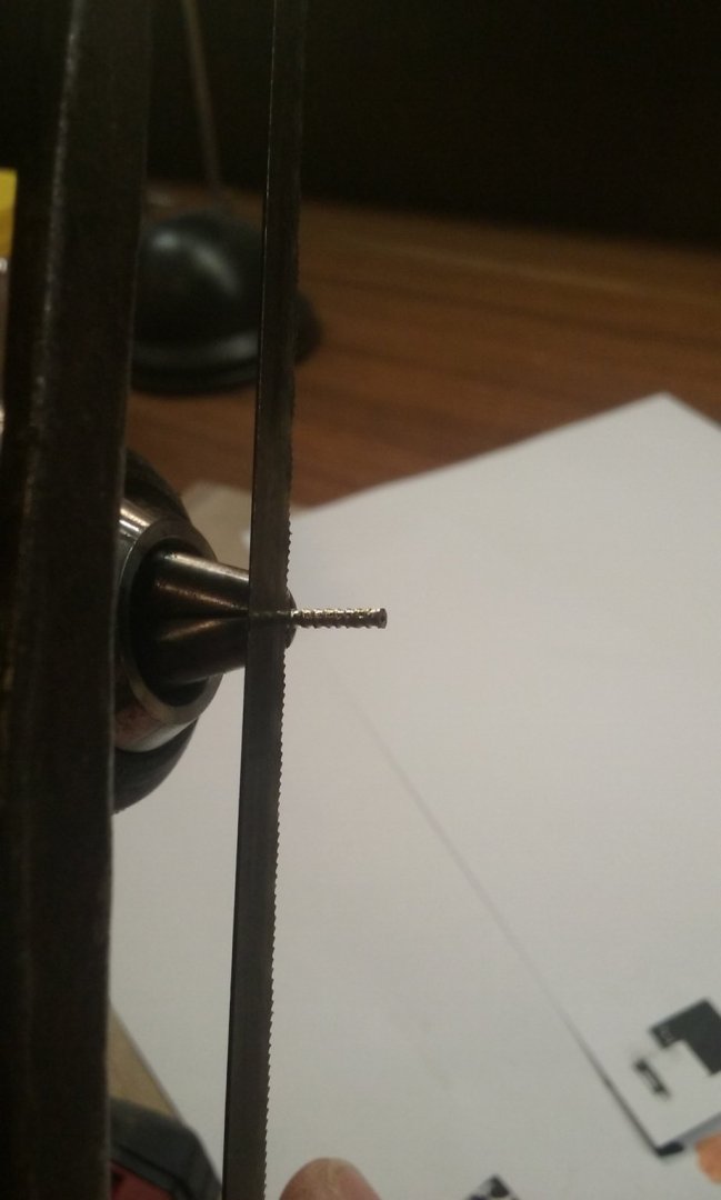
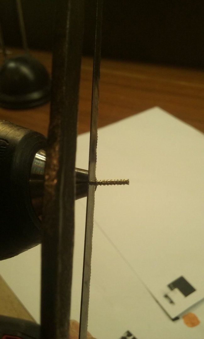
Here's the sequence I used in making the built-up cannons. Using a bit of 1.5mm brass tube set into my "poor man's lathe" - its main disadvantages are that you have to keep a finger on the start button (yes, I could bypass this but didn't bother) and that there's no support on the other end so bending of the tube is a risk. I overcame the second by sawing right up next to the jaws of the chuck, with just the combined thickness of the sawblade plus the reinforcing ring sticking out. Not so good either for the sawblade or the chuck, but I managed to get away with it. Then slide the tube out of the chuck by the same combined thickness of sawblade and reinforcing strip and do it again: (I forgot to photograph the first cut, so the above is of the second.) Then the same thing again: And again: And again and again: Last ring - full length of the barrel: And then the "magazine", using a file: And cutting the whole assembly to length


- 740 replies
-
- 6
-
-
- Tudor
- restoration
- (and 4 more)
-
Okay, another idea - using PVA, glue a piece of wood to the bottom of this section, as wide as the "sternpost" itself. As I'm not familiar with how the model goes together, I don't know if you can add all 4 strengthening pieces first, but when you no longer need the reinforcing piece dab isopropanol (which you've previously used on Il Leudo) onto the join between the sternpost and the reinforcing bit, and gently remove it. That might just work. Steven
-
I see in your post of November 25 (see photo below) that the upper frames have tenons that fit into slots in the upper planking. Is this based on contemporary representations, or did you do it to add to the strength of the upper part of the hull? I'm enjoying the build very much, by the way. A beautiful piece of work. Also, I'm very glad to see a galleon model with this particular shape of beakhead, which I've never seen in any other model galleon even though there are plenty of contemporary pictures of them. Steven
-
This is amazing work, Dan. Your attention to detail, tracking down every tiny item of such a complex vessel and representing it to scale takes my breath away. You can be justly proud of her. Steven
- 238 replies
-
- 4
-
-
- leviathan
- troop ship
- (and 2 more)
-
Ah, well - it seemed like a good idea at the time
-
Perhaps you could widen the slot in that frame, to allow for the additional thickness in the "sternpost" because of the splints? Steven
-
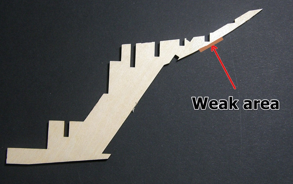
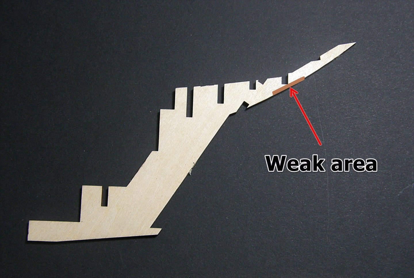
Hmm, yes that certainly is a weak point and not surprising it's coming adrift. It's a bit of a design fault on the kit manufacturer's part. Once the boat is built the rest of the structure will hold it all in place quite securely - it's just keeping it from breaking off in the meantime that you have to cope with. Will this part be visible when the model is complete? Because if not, you could glue a "splint" either side of the weak spot to strengthen it (the brown line). If it is going to be visible, the best you can do is glue it as securely as possible and be very careful not to break it off before it's reinforced by the rest of the structure. Regarding the dye, don't forget to do a test run before you dye the sails - it might turn out to be a ghastly colour completely different from what shows on the packet (don't ask me how I know). The plastic parts are just things that would be either too difficult or expensive to make in wood (or would just break the moment you look at them), and as Chris says, with proper prep they'll look just as good as the wood. Regarding the workboat, you might consider building it up on a solid carved base (called a plug), with thin frames bent around it. There are several examples of boats being made this way scattered amongst the build logs, such as archjofo's unbelievably magnificent pinnace for his model of La Créole (well above the efforts of us mere mortals) - starting on the page linked below. Steven
-
https://en.wikipedia.org/wiki/Wyuna
-
Very nice, Backer, and explains the whole thing very well. At first I thought the gonnar didn't have the nerve to stand to his gonne while firing, but the second run of shots using a slow match proved me wrong. A very impressive display. I'd read that these breech loaders were rather inefficient because it was impossible to get a good seal between the cartridge and the barrel, so a lot of the explosive gases escaped instead of propelling the ball. But maybe not, looking at this video. I certainly wouldn't want to be on the wrong end of something like that. It seems to me though, that the gun wasn't built up from wrought iron staves, unless the finish is a lot better than would normally be expected. Maybe because of safety rules? Steven
- 740 replies
-
- 2
-
-
- Tudor
- restoration
- (and 4 more)
-
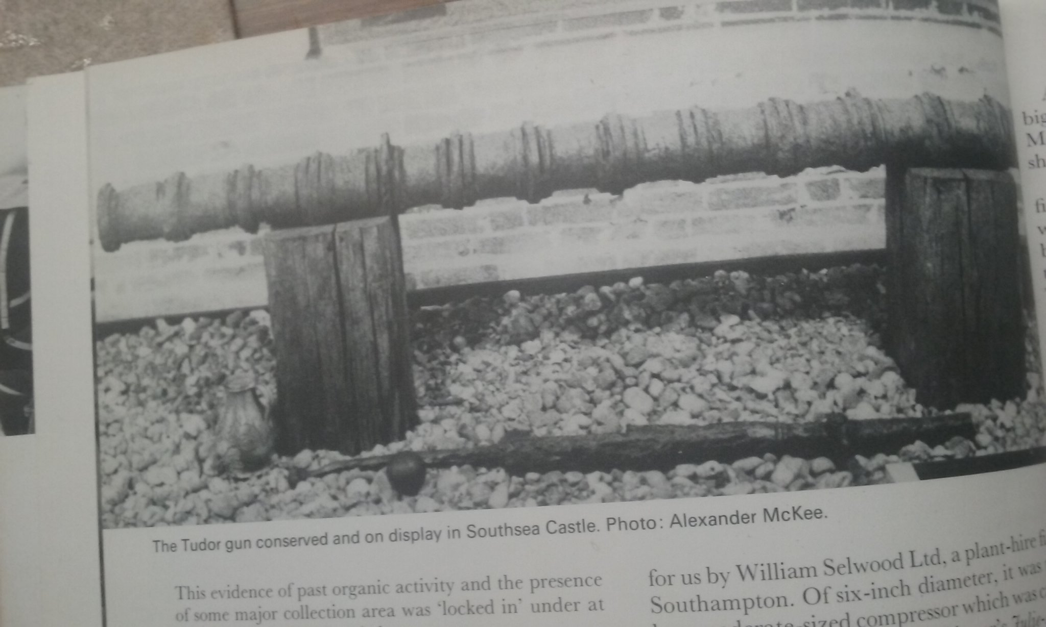
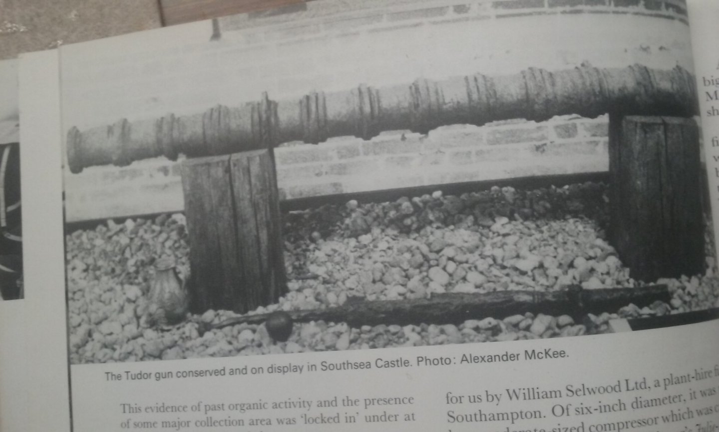
Roger, I seriously doubt it - I'm working at 1:200 scale - a tiny error at that scale would be enormous in the real world. (But I appreciate the thought ) Mark, thanks for these. There's so much variation in what was in use - the two middle ones are swivels, with the breechblock very evident (and there's a magazine at the bottom of the display). The two bottom ones appear to be stave-built (made of strips of wrought iron edge to edge in a circle to form the barrel), with reinforcing bands shrunk on to keep the thing from blowing apart when fired. The other two - wrought into a tube-shape by a blacksmith? And here's a photo and a diagram of how this breechloader at least worked: And then there are cast bronze guns which were used for the main armament, which were muzzle-loaders much more like those we're all used to, and changed very little over the centuries. According to the Anthony Roll ( https://en.wikisource.org/wiki/Anthony_Roll ) of 1545, the Great Harry had the following crew and guns (numbers in Roman numerals): Men Souldiours - cccxlix Marryna[r]s - cccj Gonnars [gunners] - l [total:] vijc For the Harry Grace a Dieu Ordenaunce, artillary munitions, habillimentes for the warre, for the armyng and in the deffence of the sayd shyppe to the see Gonnes of brasse Cannons - iiij Demy cannons - iij Culveryns - iiij Demy culveryns - ij Sakers - iiij Cannon perers - ij Fawcons - ij Gonnes of yron Porte pecys [port pieces] - xiiij Slynges - iiij Demy slynges - ij Fowlers - viij Baessys - lx Toppe pece - ij Hayle shotte pecys - xl Handgonnes complete - c All in all a fascinating subject. Steven
- 740 replies
-
- 5
-
-
- Tudor
- restoration
- (and 4 more)
-
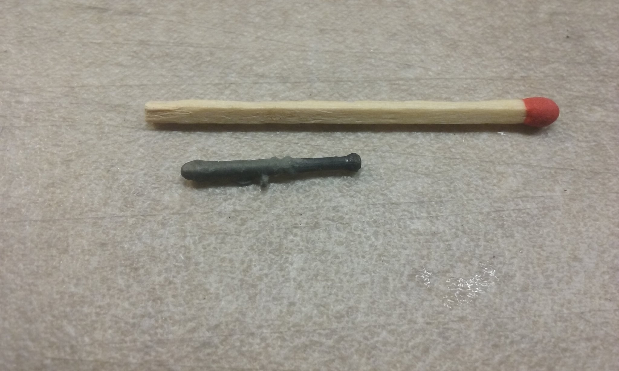
By the way, these guns are breech-loaders. The narrower bit at the left hand end of the newer one is supposed to represent the "breechblock" where the "magazine" is inserted. Not exactly sure how these things worked, but apparently this is what they looked like. Steven
- 740 replies
-
- 4
-
-
- Tudor
- restoration
- (and 4 more)
-
Well, my technique has improved. Here is a comparison between the first gun barrel I made and the most recent. I've got the reinforcing bands much narrower and (at least in my eye) the whole thing looks better. Note also that the first one is shorter than the last, due to my having got my maths wrong when I scaled it down from the photo. But that really doesn't matter, because all these guns will be sticking out of arched ports in the ship, with the inboard end concealed. And anyway guns of the time were not standardised at all. The new one is the right length, but both are a little too thick (1.5mm brass tube), but not so much that they would be outside the normal variation in gun sizes. The differences in detail are so tiny that they're pretty much invisible to the naked eye. So I'll be keeping all the guns I've made so far and using them in the ship. Steven
- 740 replies
-
- 8
-
-
- Tudor
- restoration
- (and 4 more)
-
Hi Peter, The main thing to do is to sand the first layer of planking so you get a very smooth run in every direction. This is your opportunity to even out any lumps and bumps that disturb the smooth curve of your ship's outer form, to form a good base for your second layer of planking. If there are any gross problems a bit of wood filler or builder's bog is ok to use at this stage (as it will be hidden by the second layer of planking), then sand it all smooth. It seems to me it's already very good, but closer inspection may show up some inequalities that need to be dealt with. It's looking very good, and taking on that beautiful characteristic carrack shape. You're making very good progress. Steven
-
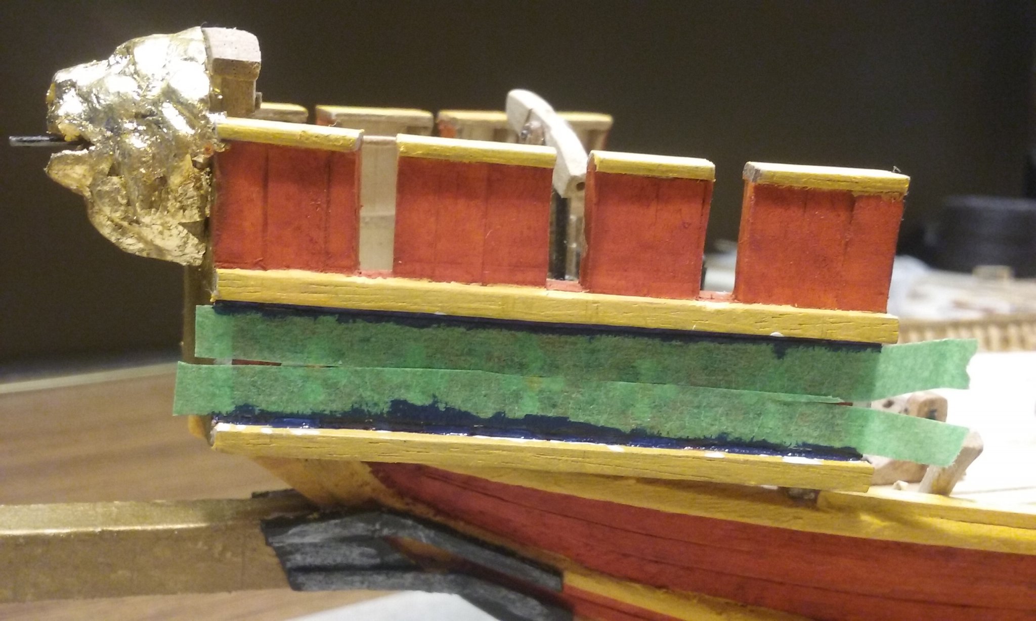
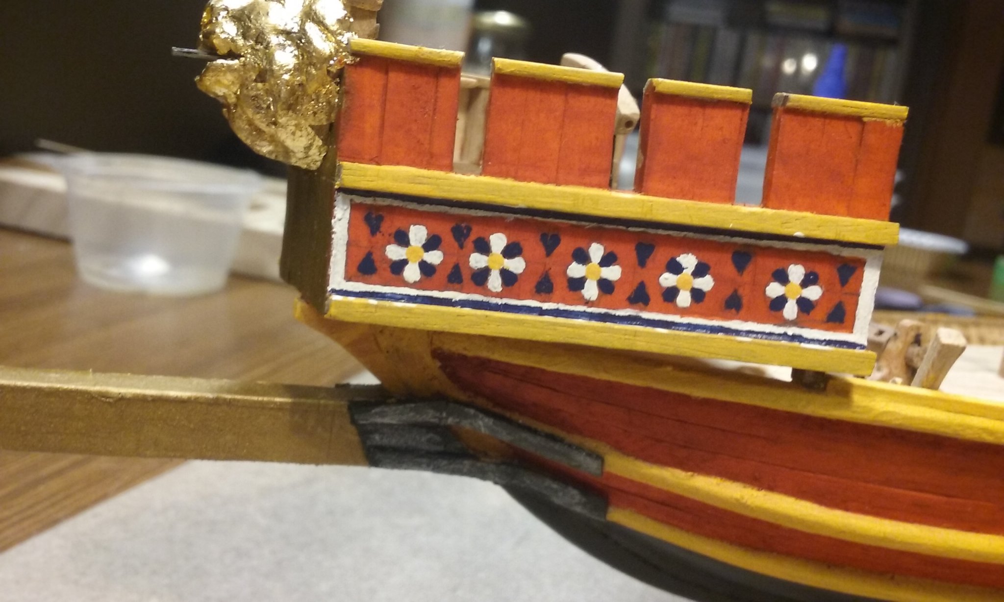
An update on the painting of the pseudopation: Masking: Masking taken off: It does look better to the naked eye than on a close-up photo, but I'm still not totally happy with the precision of the decorated border. However, I think I can improve on it before I finalise the whole thing, add the lower oars and close up the upper deck.


-
I have to make cannons for the aftercastle before I can add the upper deck to it. Back in the day I made a "cast bronze" cannon out of type metal (remember that stuff?) cast in plaster of Paris. I need to do some tidying up and somehow add a trunnion before I can cast more of them. And type metal is completely unavailable nowadays . . . But for the upper deck cannons I'll need "built-up" cannons, as found on the Mary Rose: Here's my first attempt. Not as precise as I'd like, but to the naked eye it looks pretty good. Note the "poor man's lathe", using a very thin file and a tiny hacksaw to cut the grooves. Another 13 to make. And here are the two guns together. Steven

- 740 replies
-
- 11
-
-
- Tudor
- restoration
- (and 4 more)
-
MONTAÑES by Amalio
Louie da fly replied to Amalio's topic in - Build logs for subjects built 1751 - 1800
Exquisite work! -
Beautiful detail work, Dick. Very impressive. Steven
- 263 replies
-
- 1
-
-
- nave tonda
- round ship
- (and 2 more)