Louie da fly
-
Posts
7,990 -
Joined
-
Last visited
Content Type
Profiles
Forums
Gallery
Events
Everything posted by Louie da fly
-
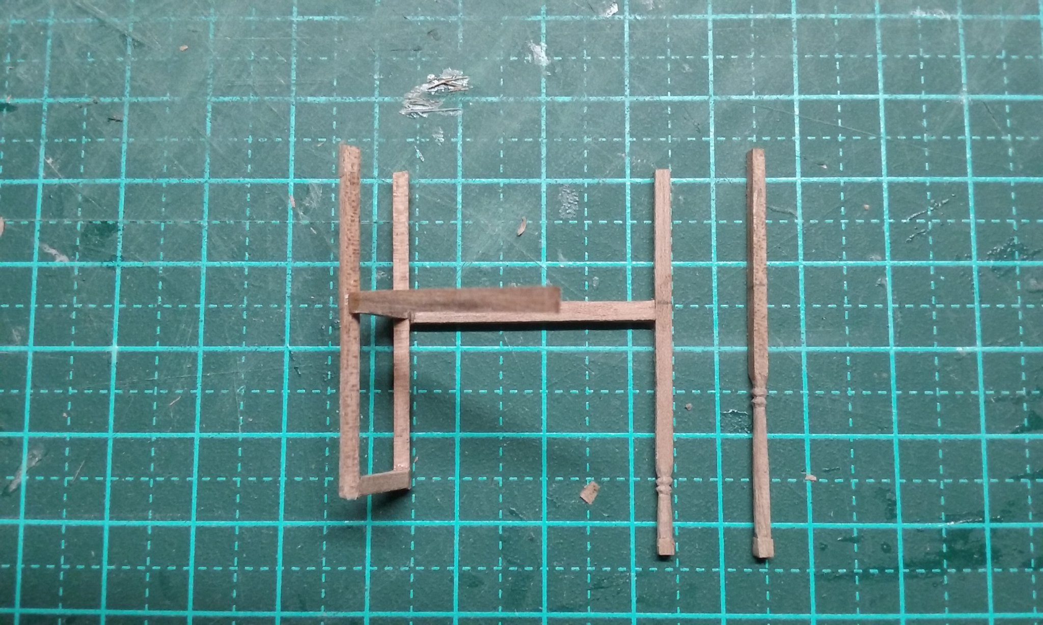
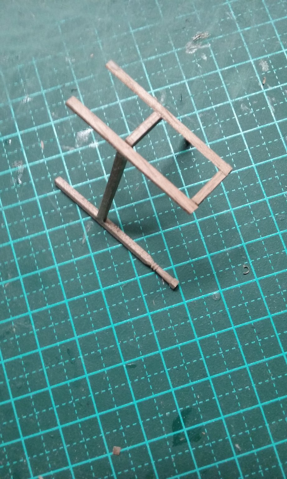
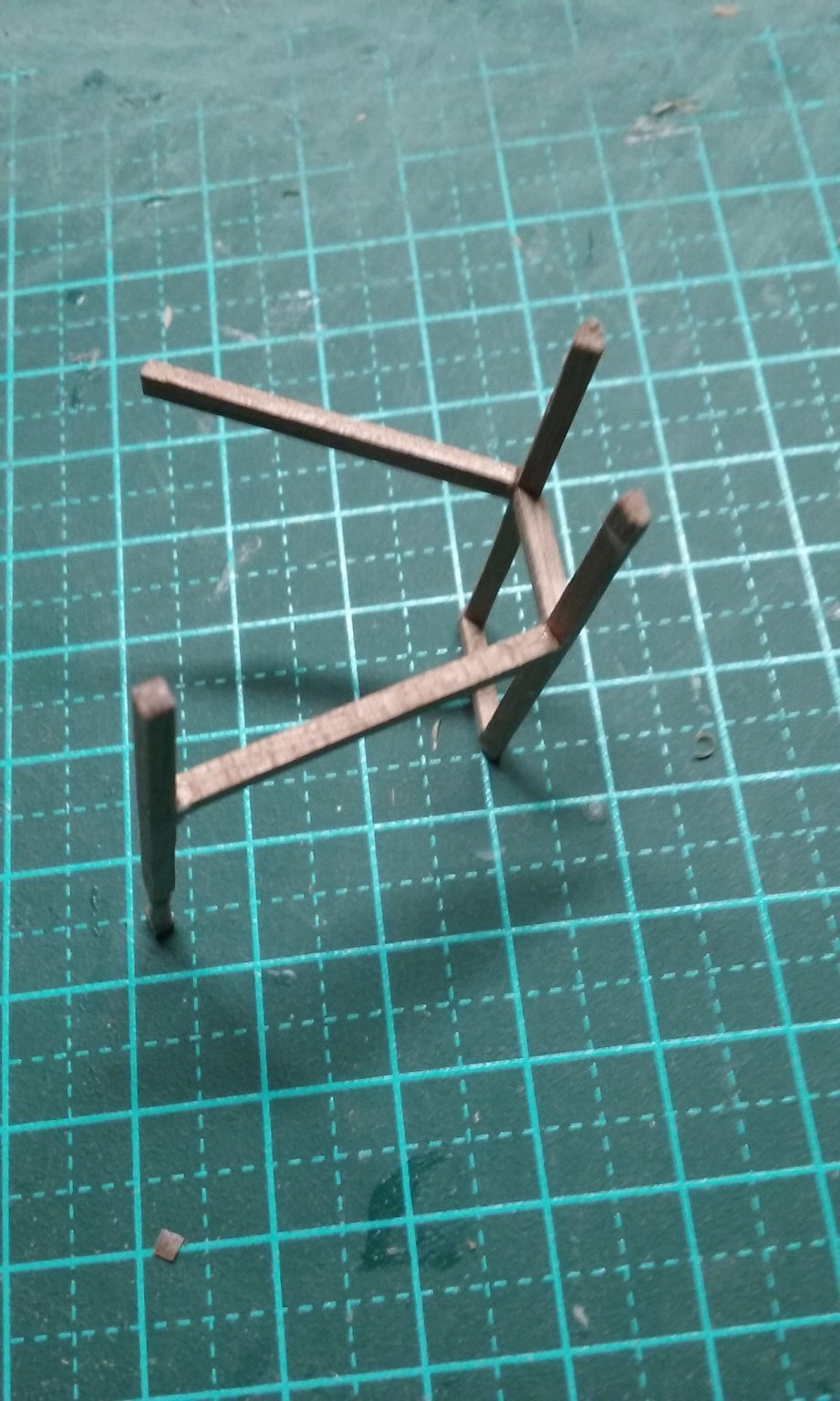
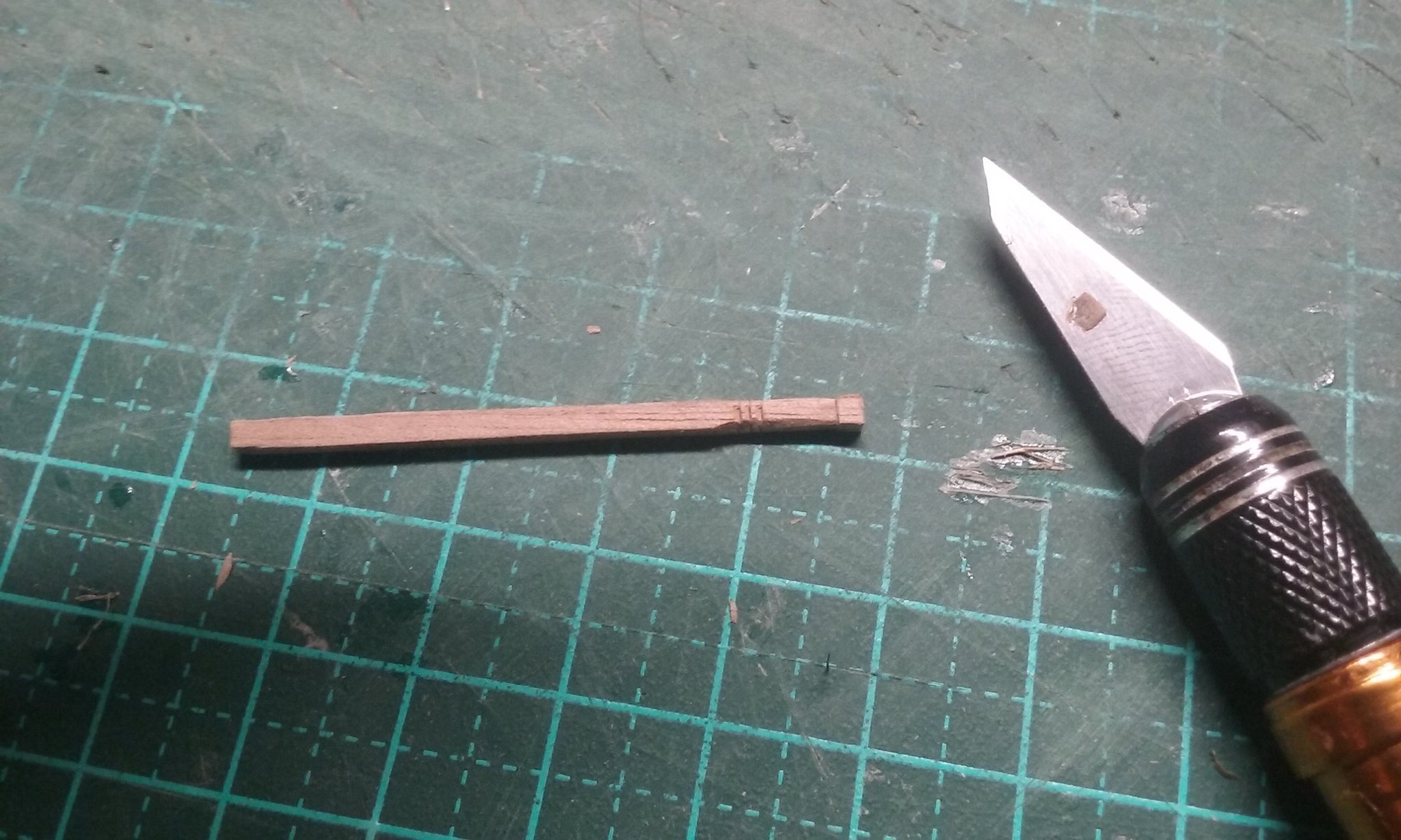
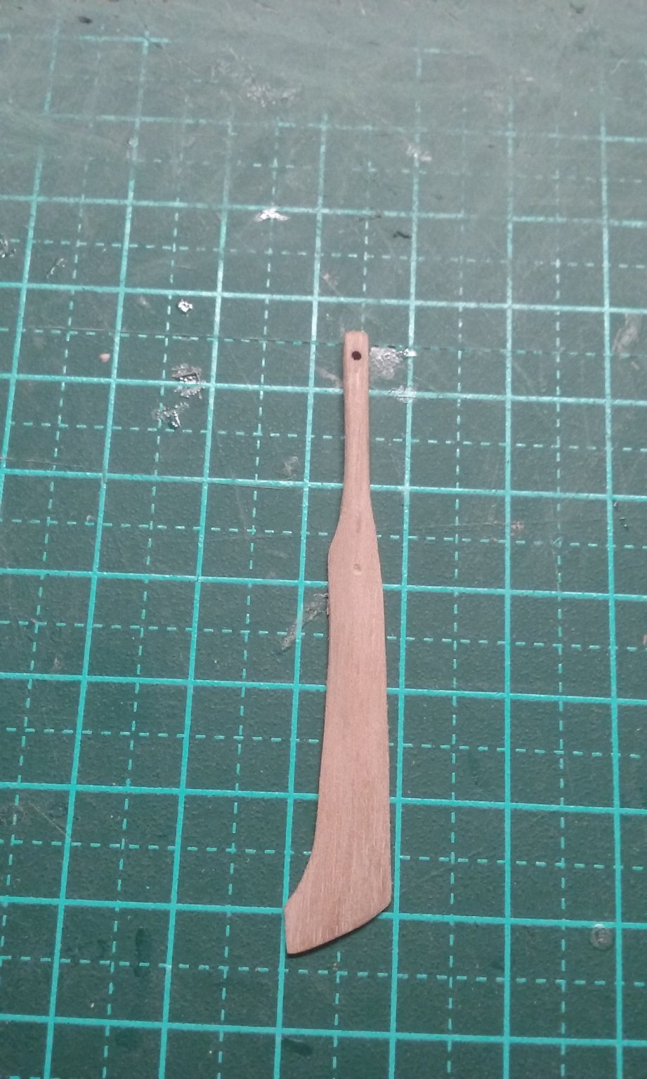
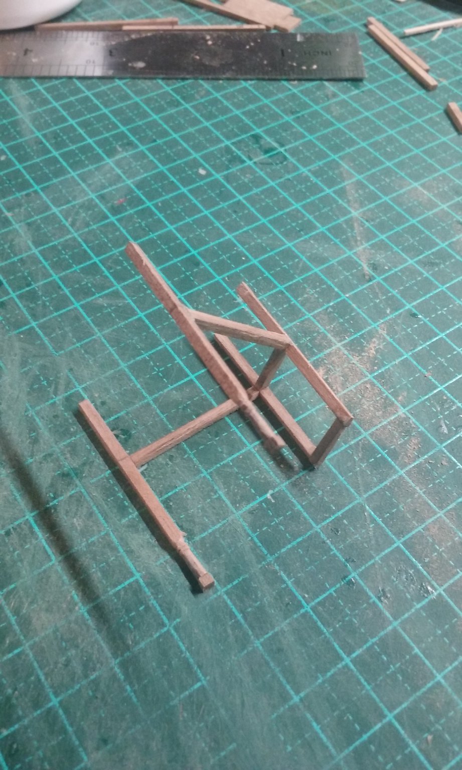
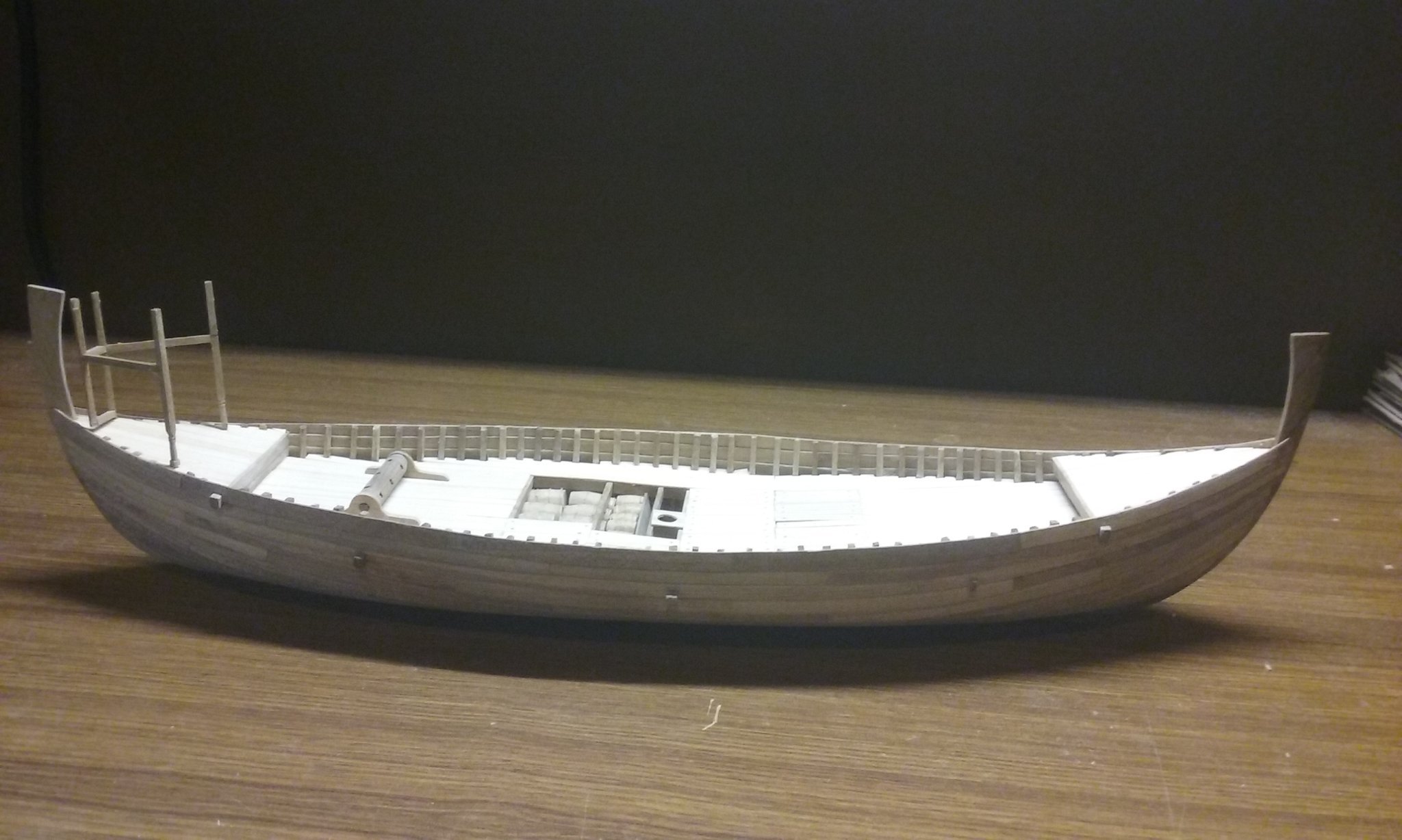
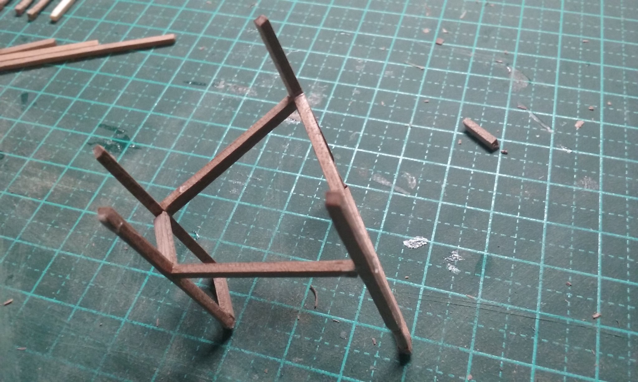
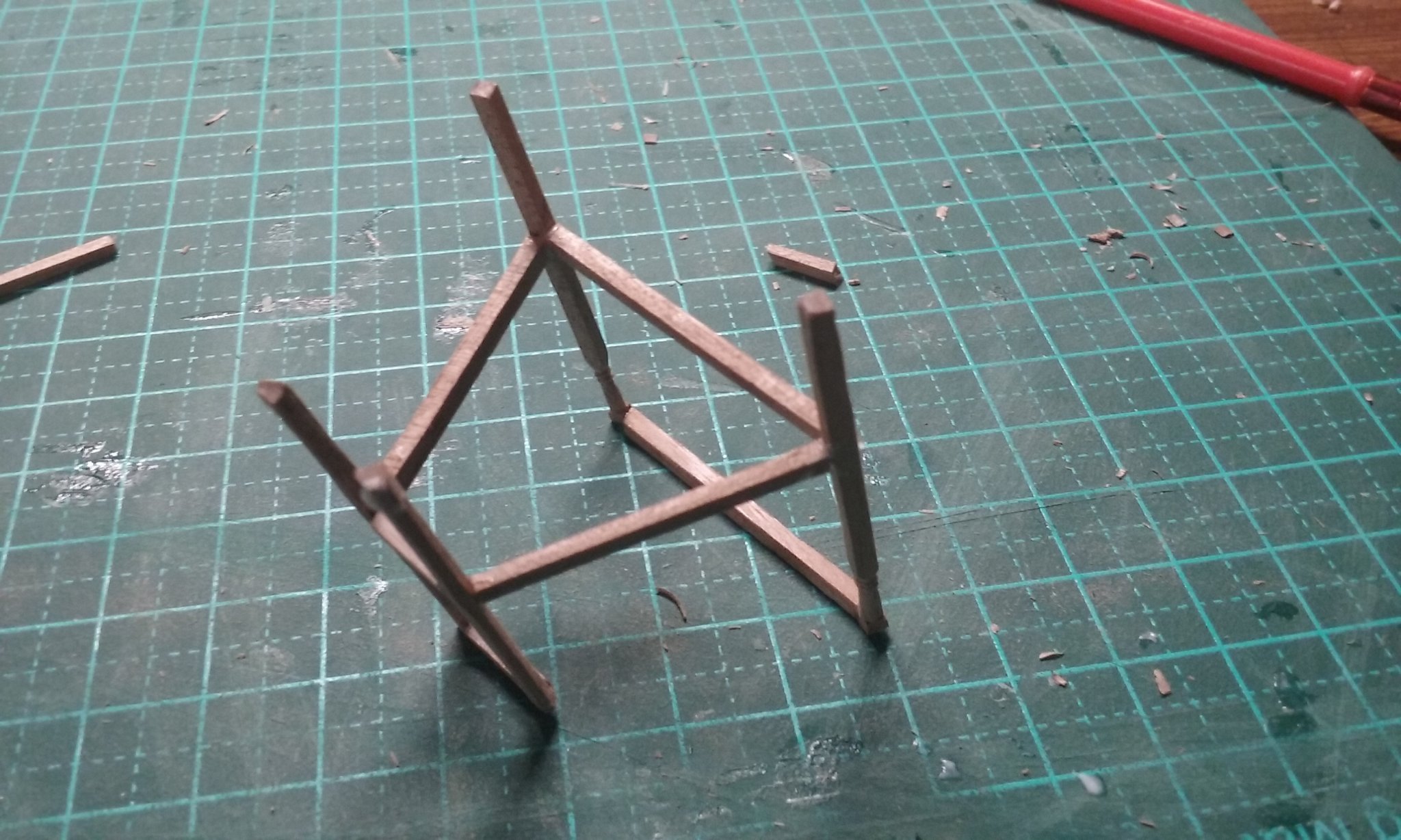
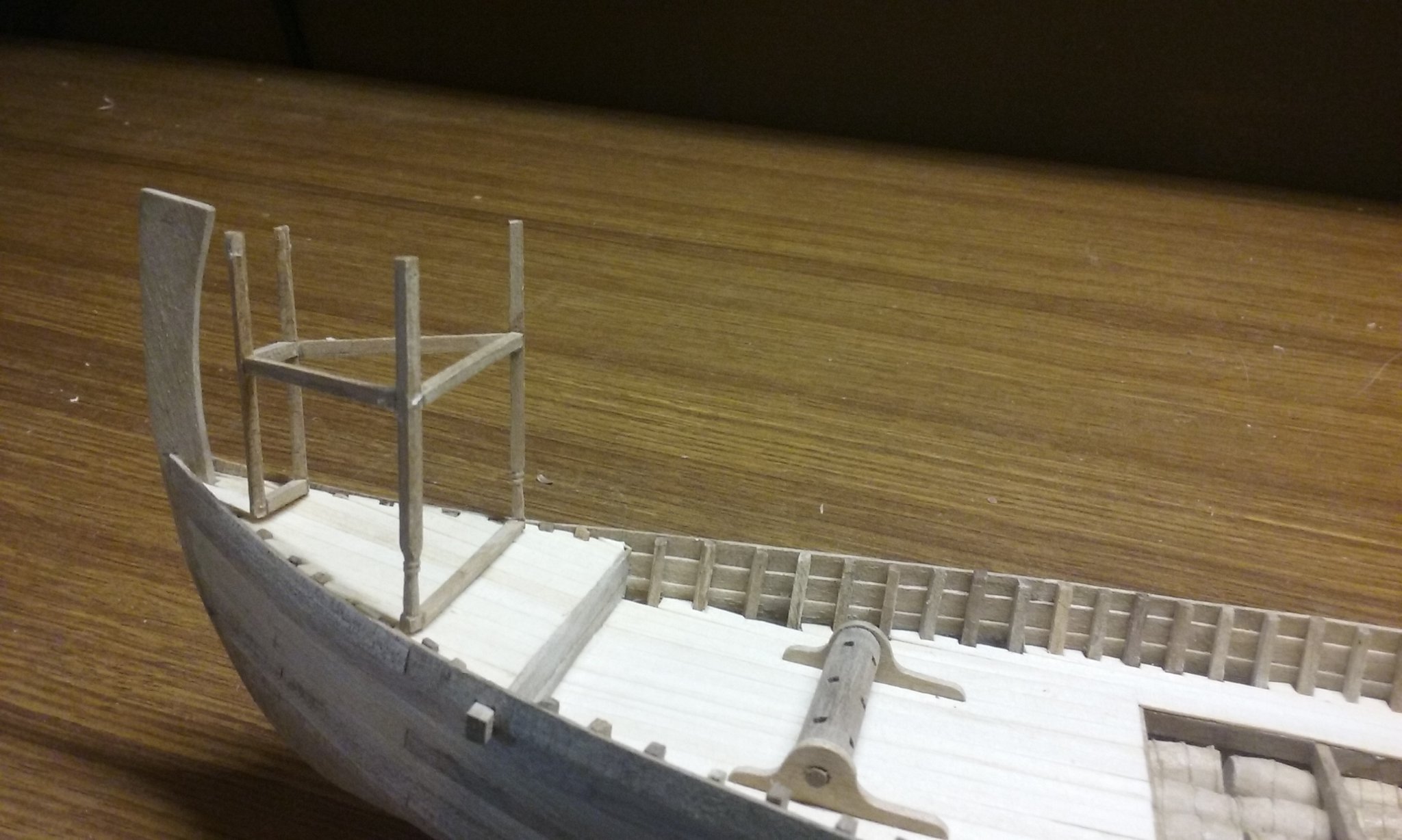
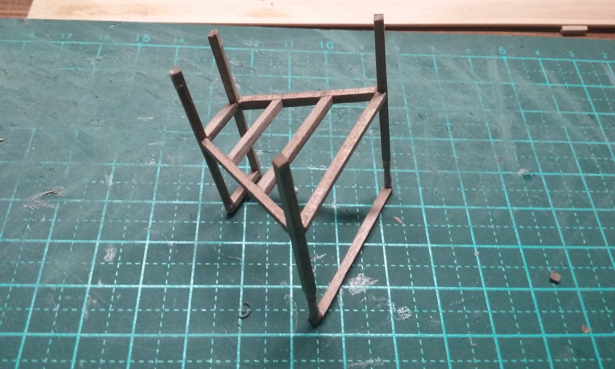
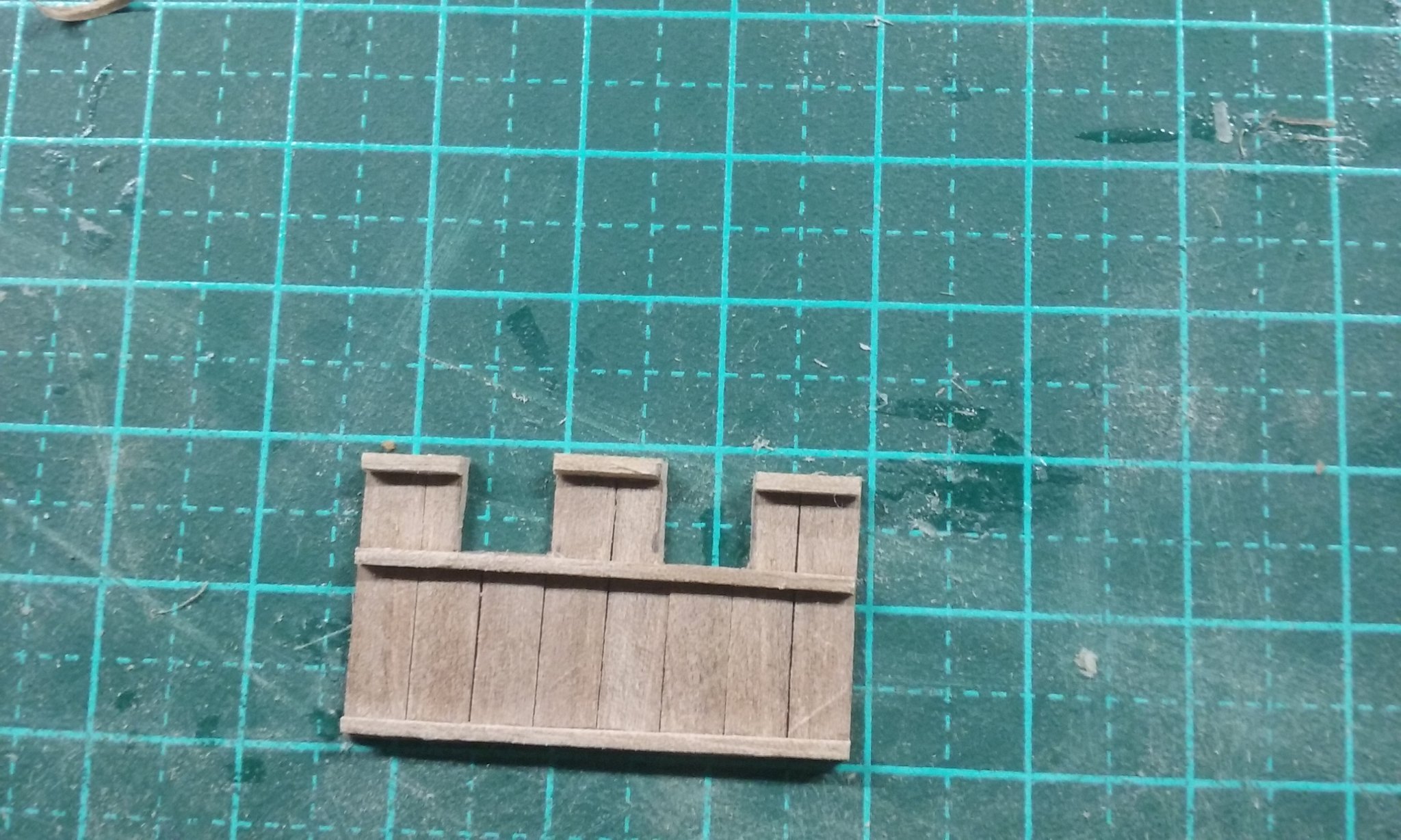
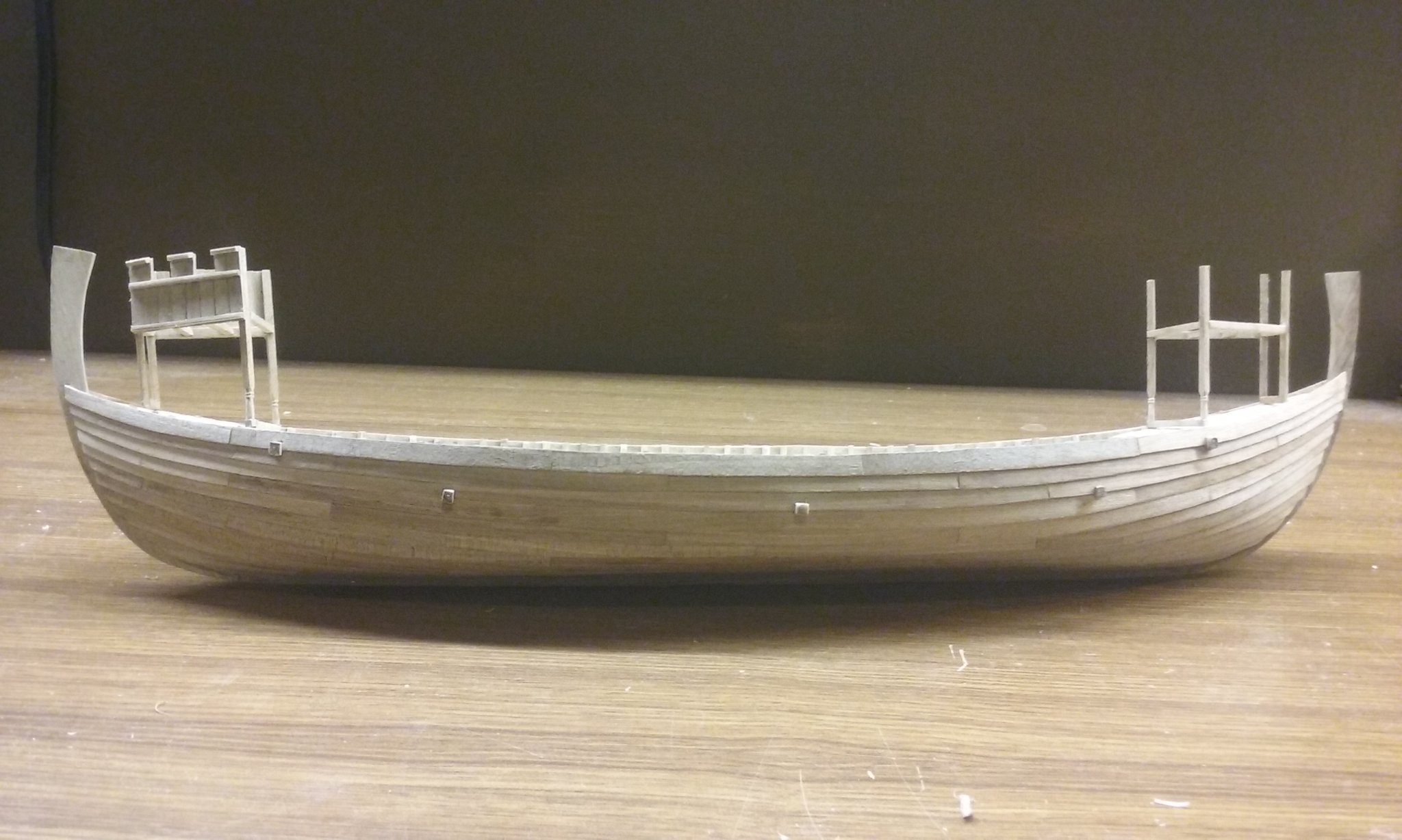
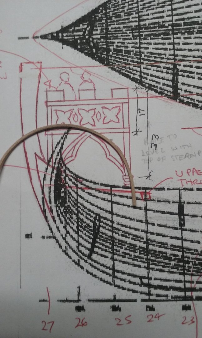
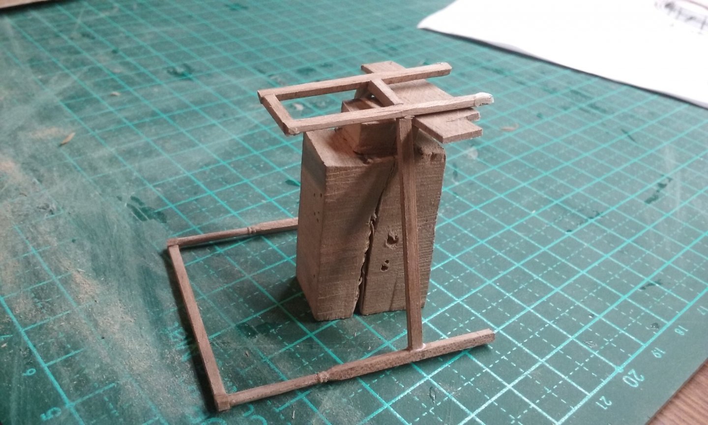
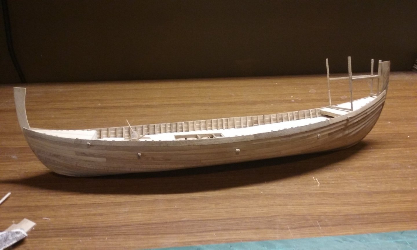
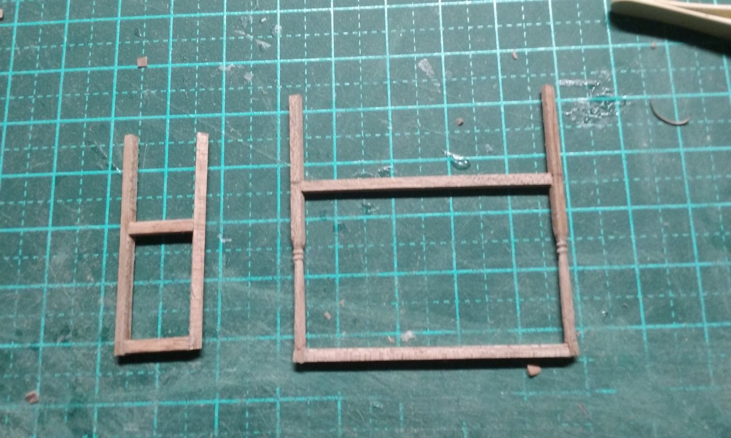
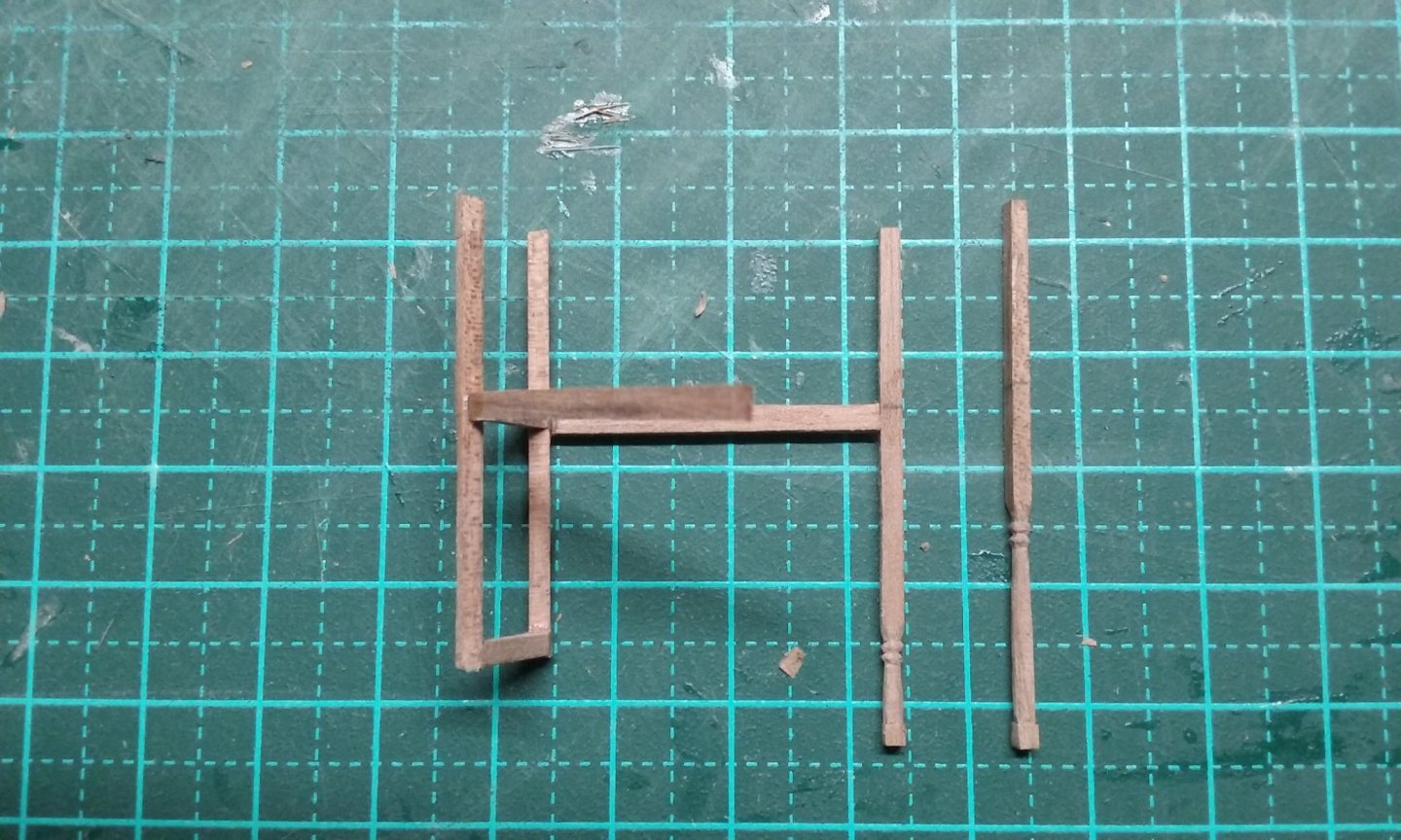
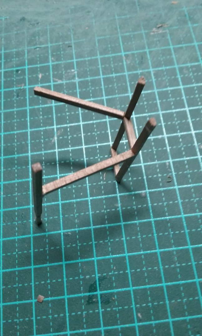
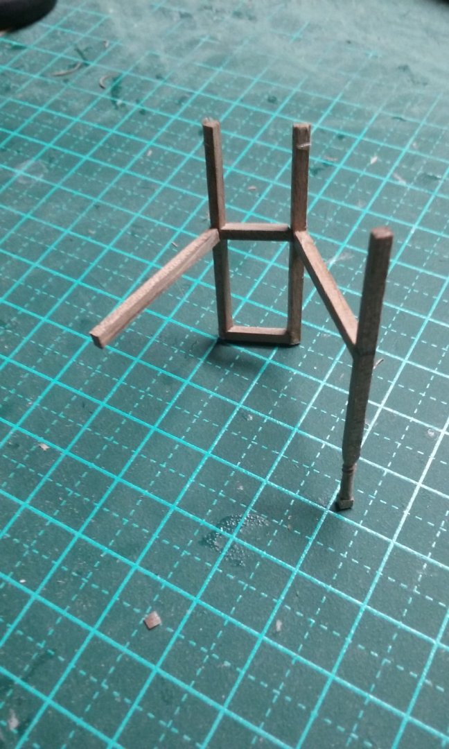
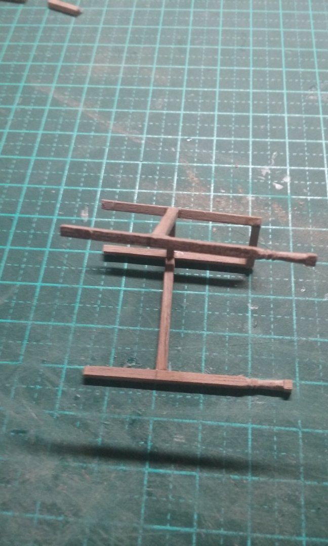
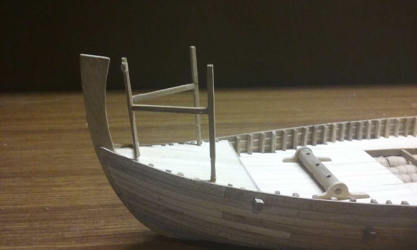
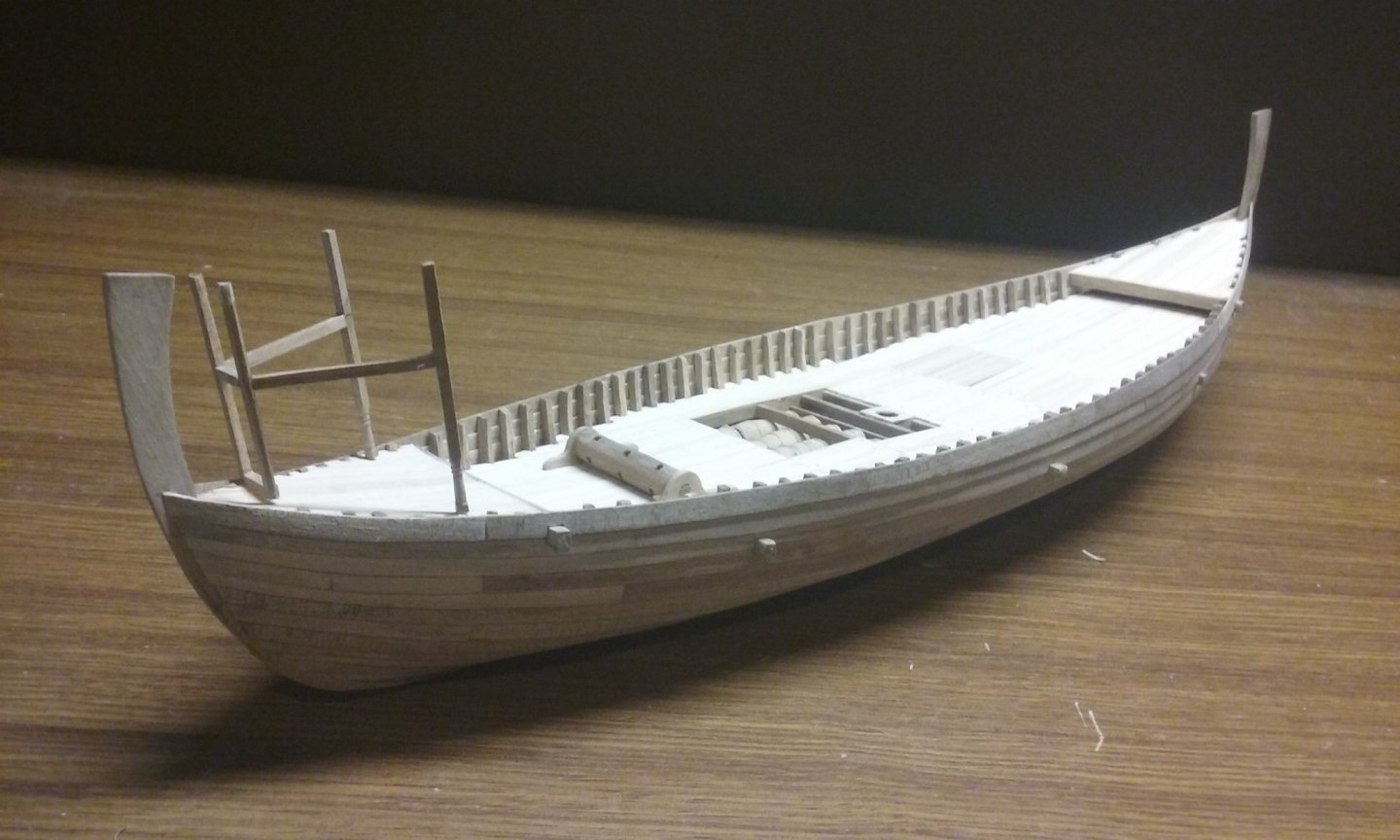
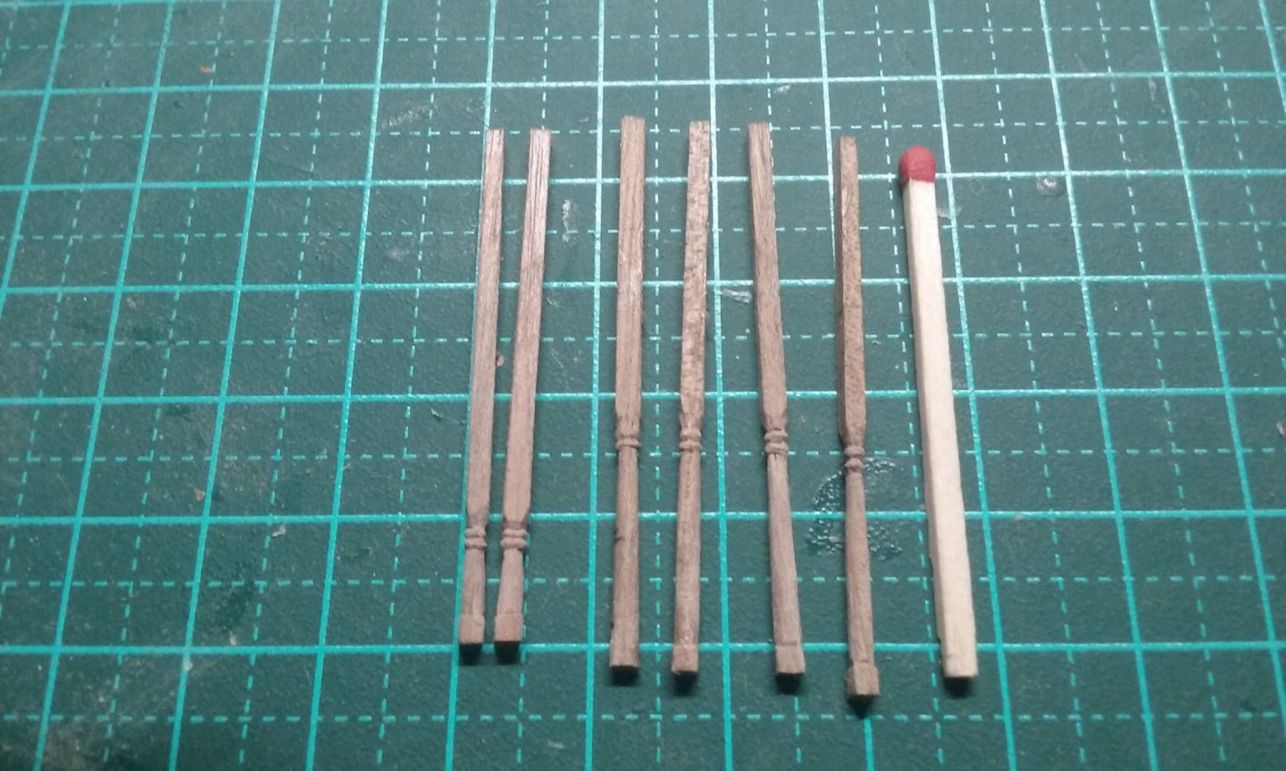
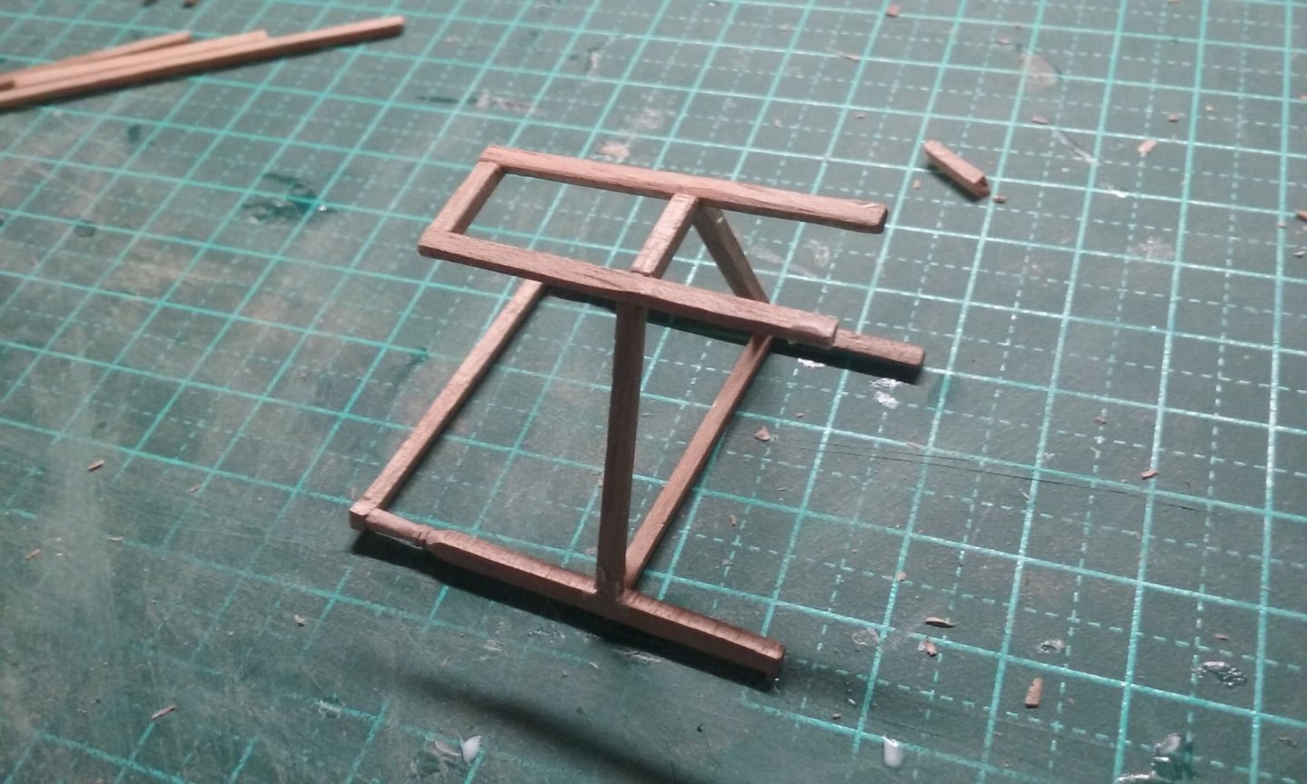
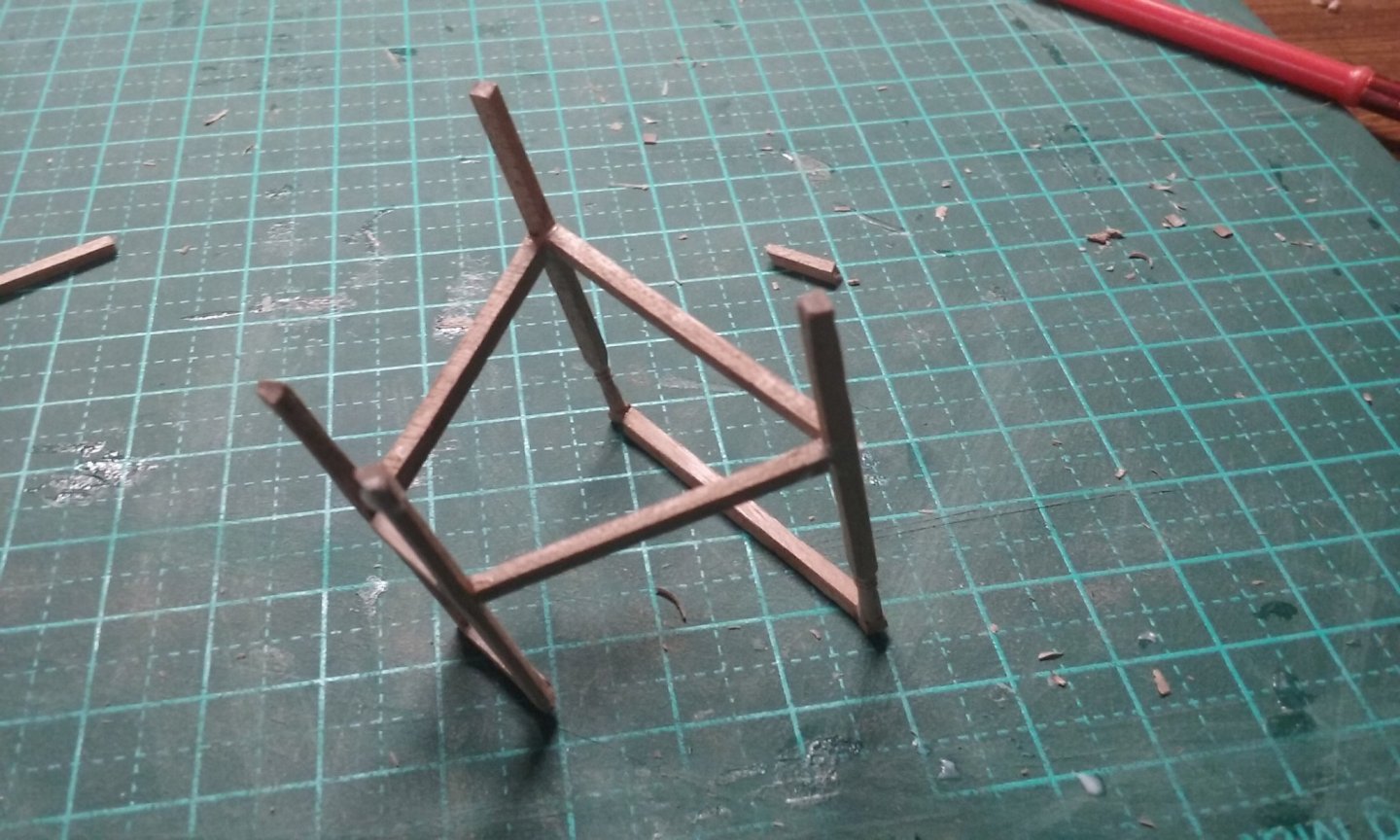
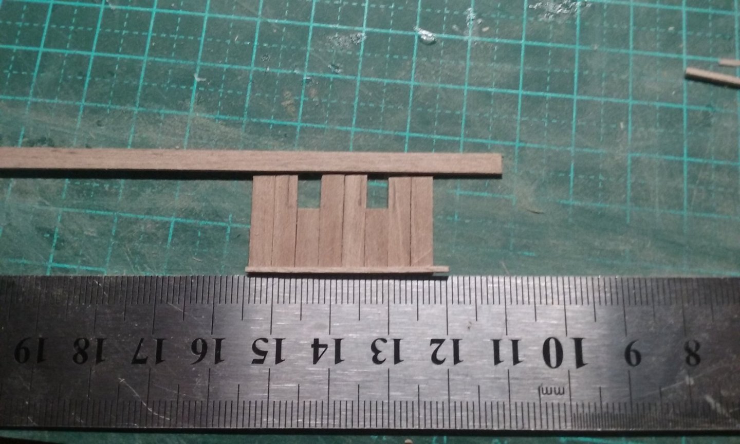
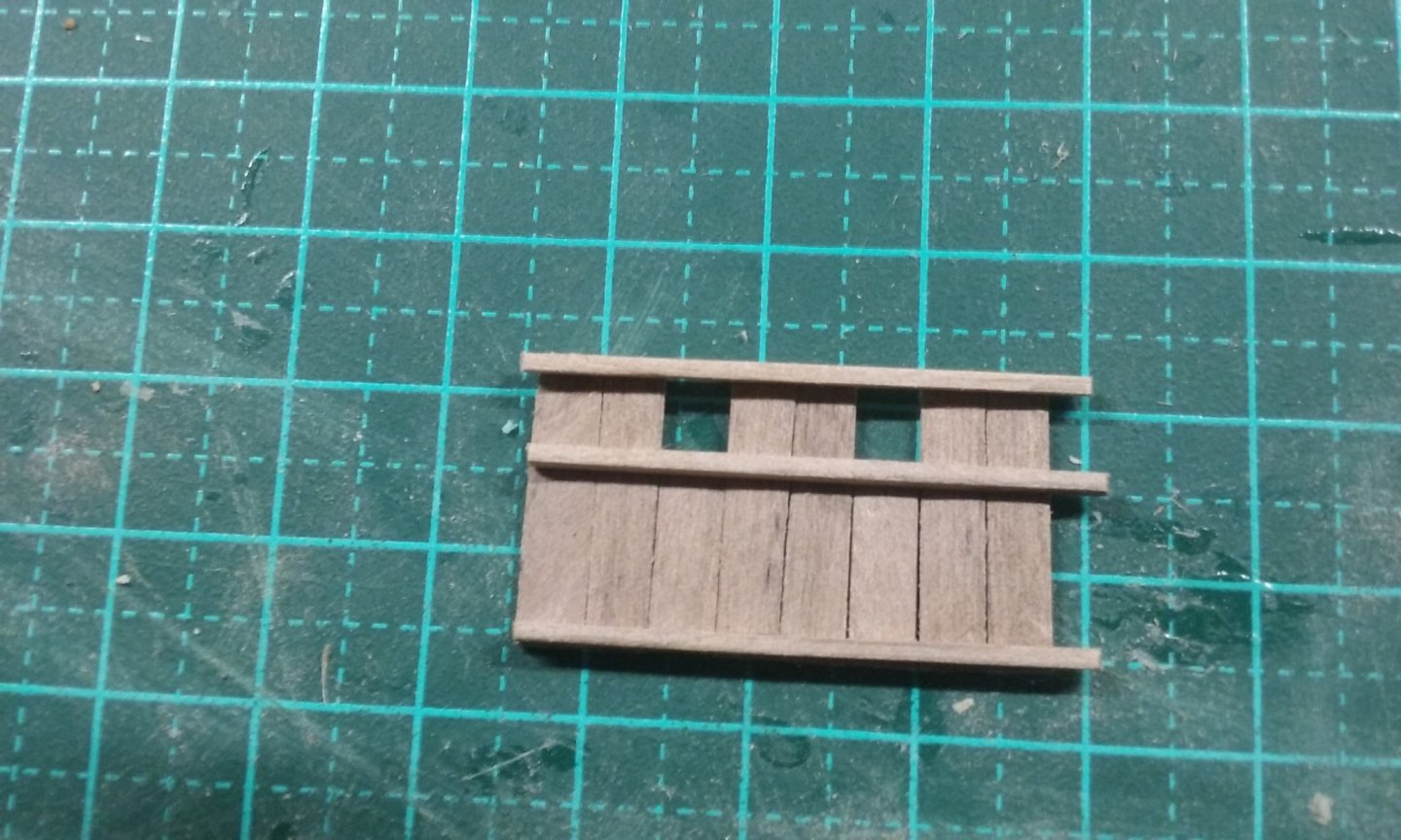
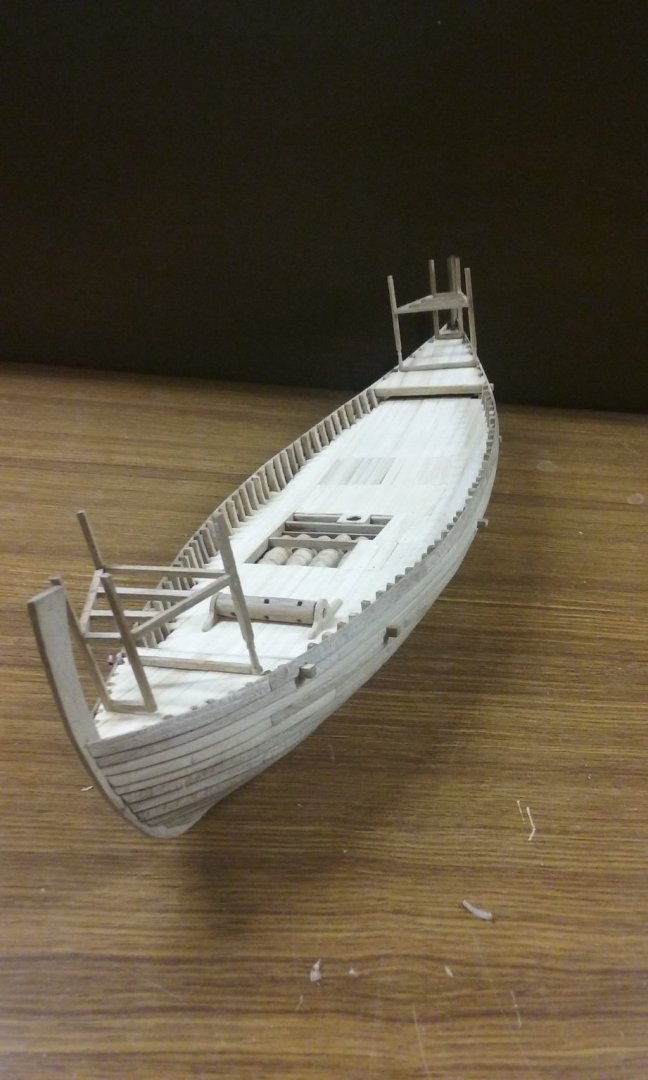
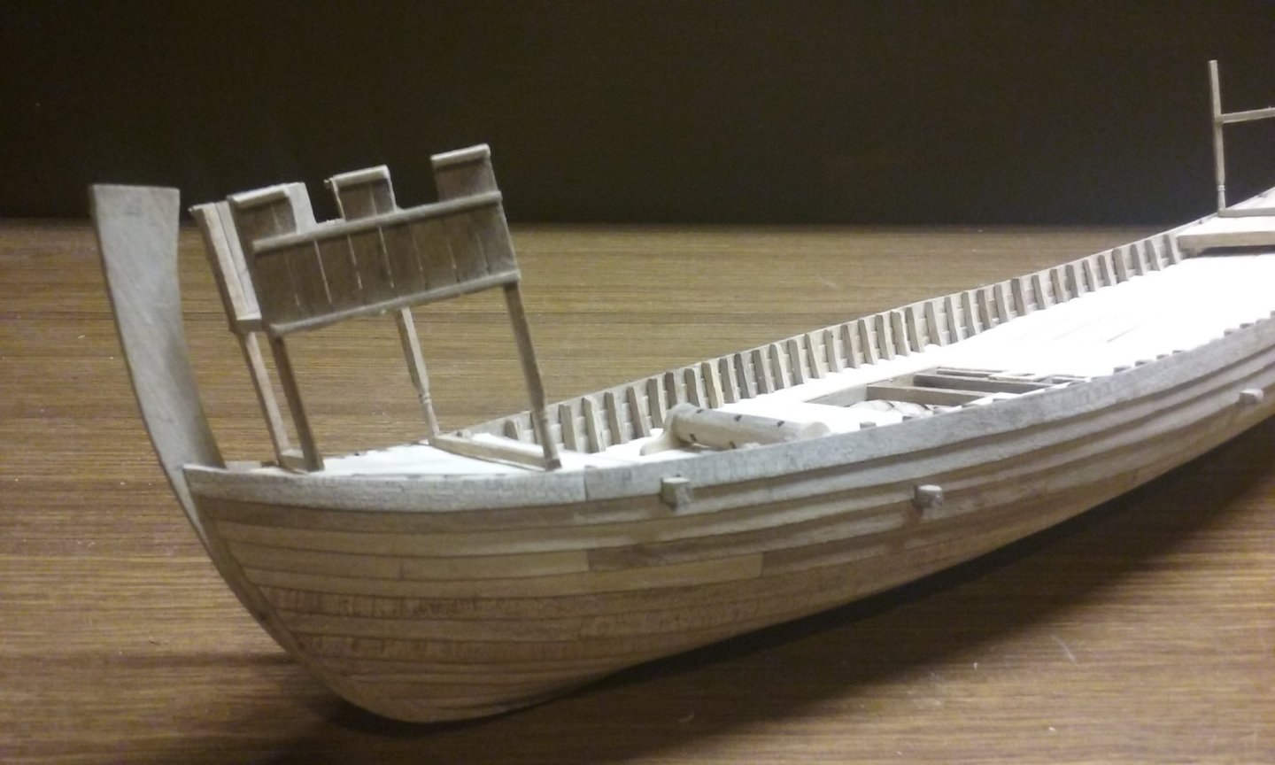
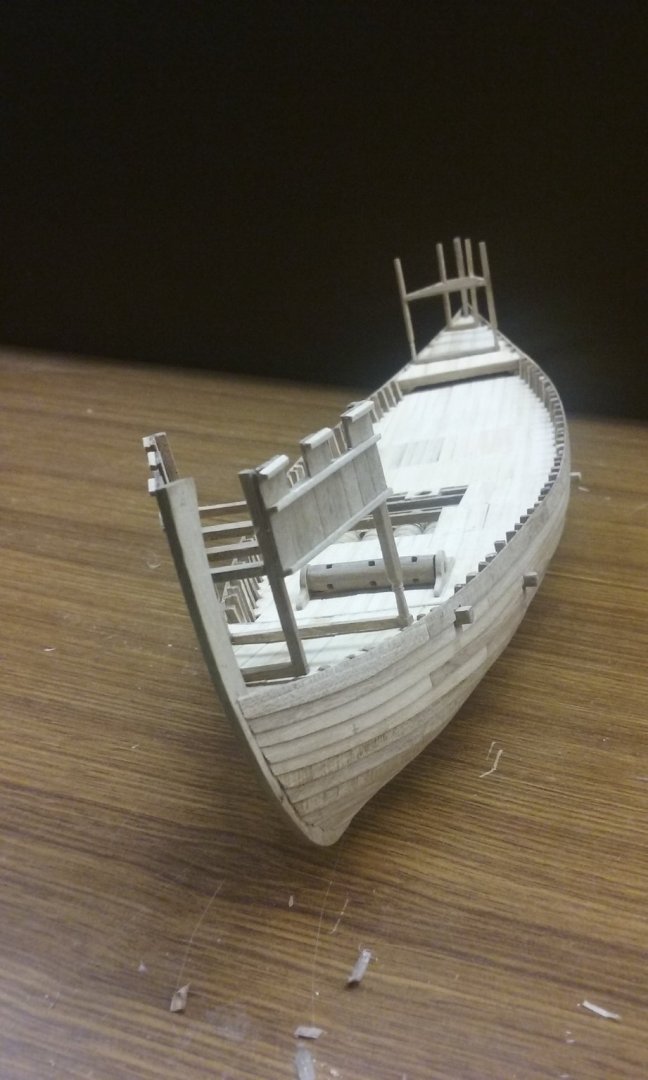
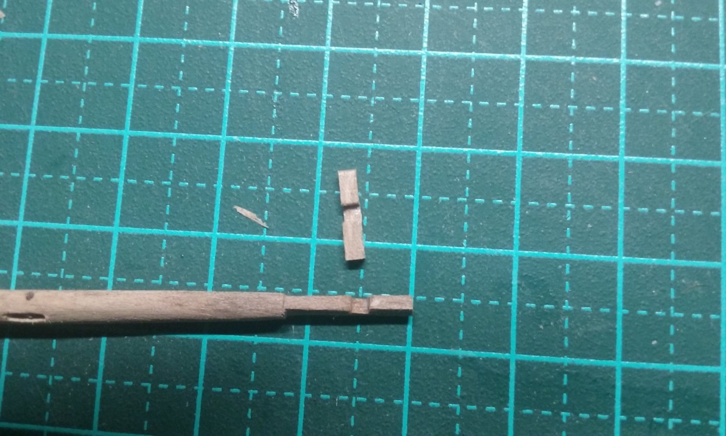
 And now to work on the castles. This took a lot of trial and error - the foredeck and after deck are considerably angled to the horizontal, so the uprights supporting the castles are shorter at the outer end than the inner. I had to guess the difference and found I'd got it wrong - after I'd carved nice supporting columns into the inner uprights. The photo below shows the original uprights on the right and two of the new ones on the left. I had to do a lot of figuring how to build these things so they would work. The floor plan is a truncated triangle, and they had to be without a top crossbeam at the rear because most castles in contemporary pictures don't have a back wall. I think I ended up with something worthwhile, and better (and tidier) than the castles on my previous build, the dromon. The pictures below are of the original version, with the longer columns. And here is the original castle structure part assembled. And roughly in place to get an idea of what it would look like. And the new version, showing the old upright next to it. I also discovered I'd made the castles too long fore and aft, so I had to change that too. A lot of pulling apart and rebuilding, but mostly I just needed to cut various existing pieces shorter - it was only the uprights with the long columns that had to be re-made. Here's a column being carved into shape. More progress: Deck beams in place: And the walls under construction. Glued to the frame and again roughly positioned: the end wall is not yet made. I've started bending wood to make the decorative arches and other features. Oh, and here's the side rudder, ready to be put in position. Coming along . . . Steven
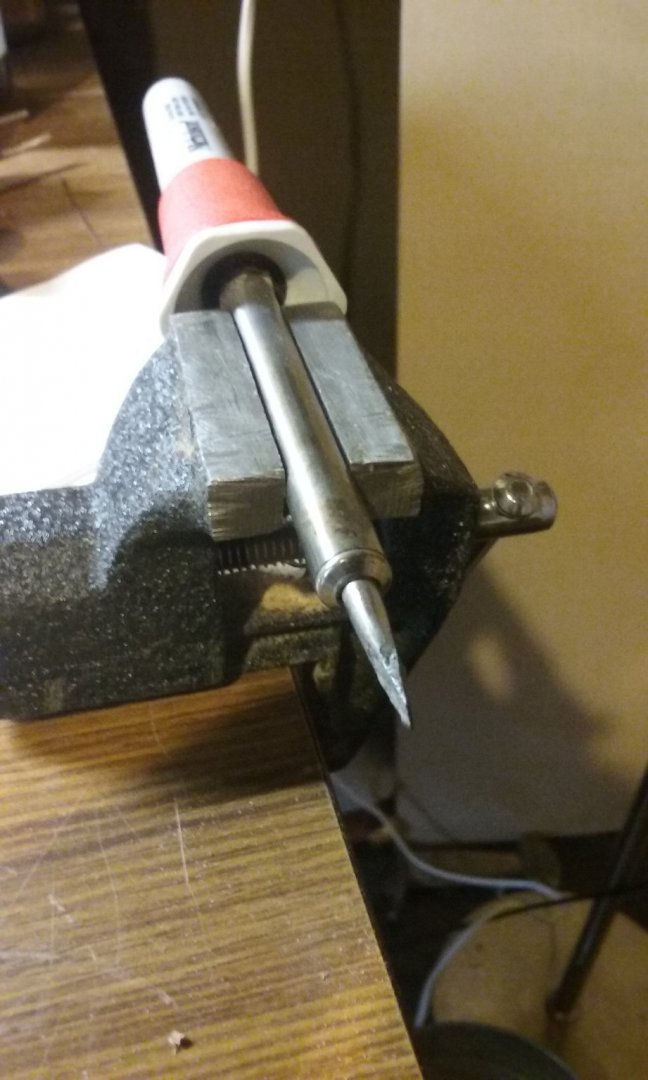


- 327 replies
-
- 18
-

-

-

-
You've done a beautiful job on those eyes. They turned out very well. Steven
- 62 replies
-
- 2
-
-
-
- amati
- greek bireme
- (and 1 more)
-
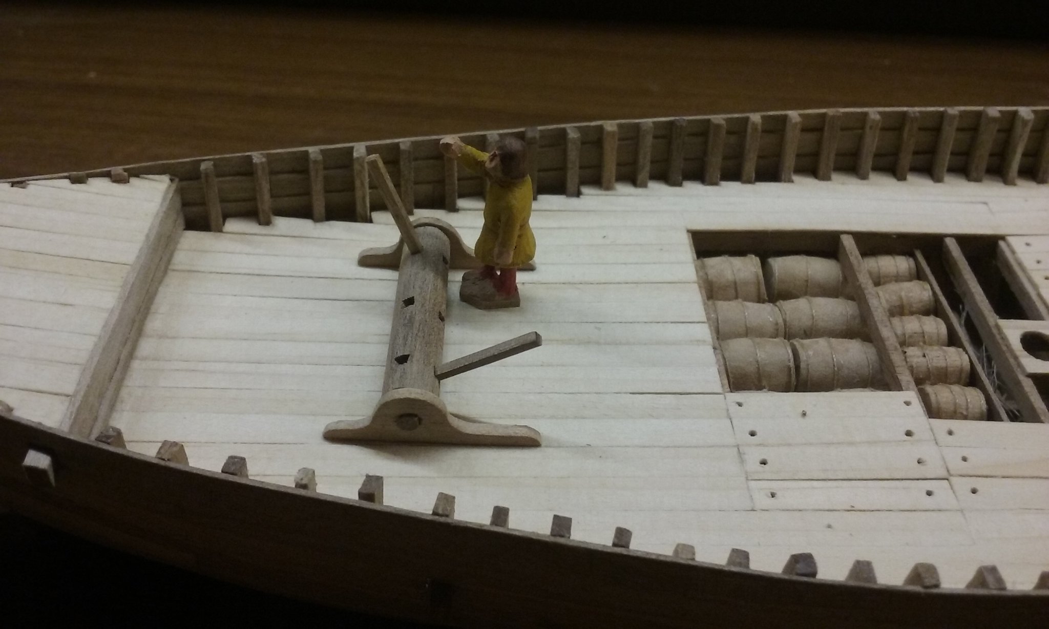
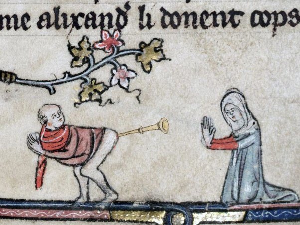
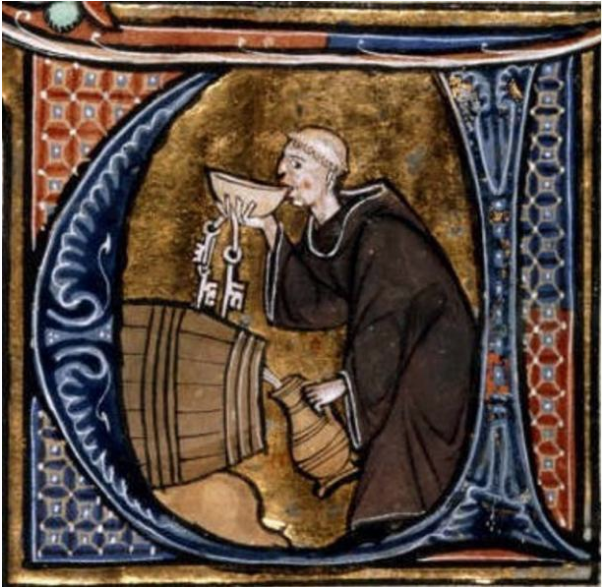
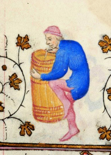
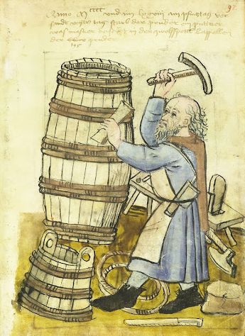
Well, he's not really anything to do with the windlass - I've still got to carve the two guys who'll be working it. He's actually a buisinier (trumpeter), but I don't think he'll be playing it like this (genuine mediaeval drawing from a manuscript - they were a rather earthy crowd.) Steven
-
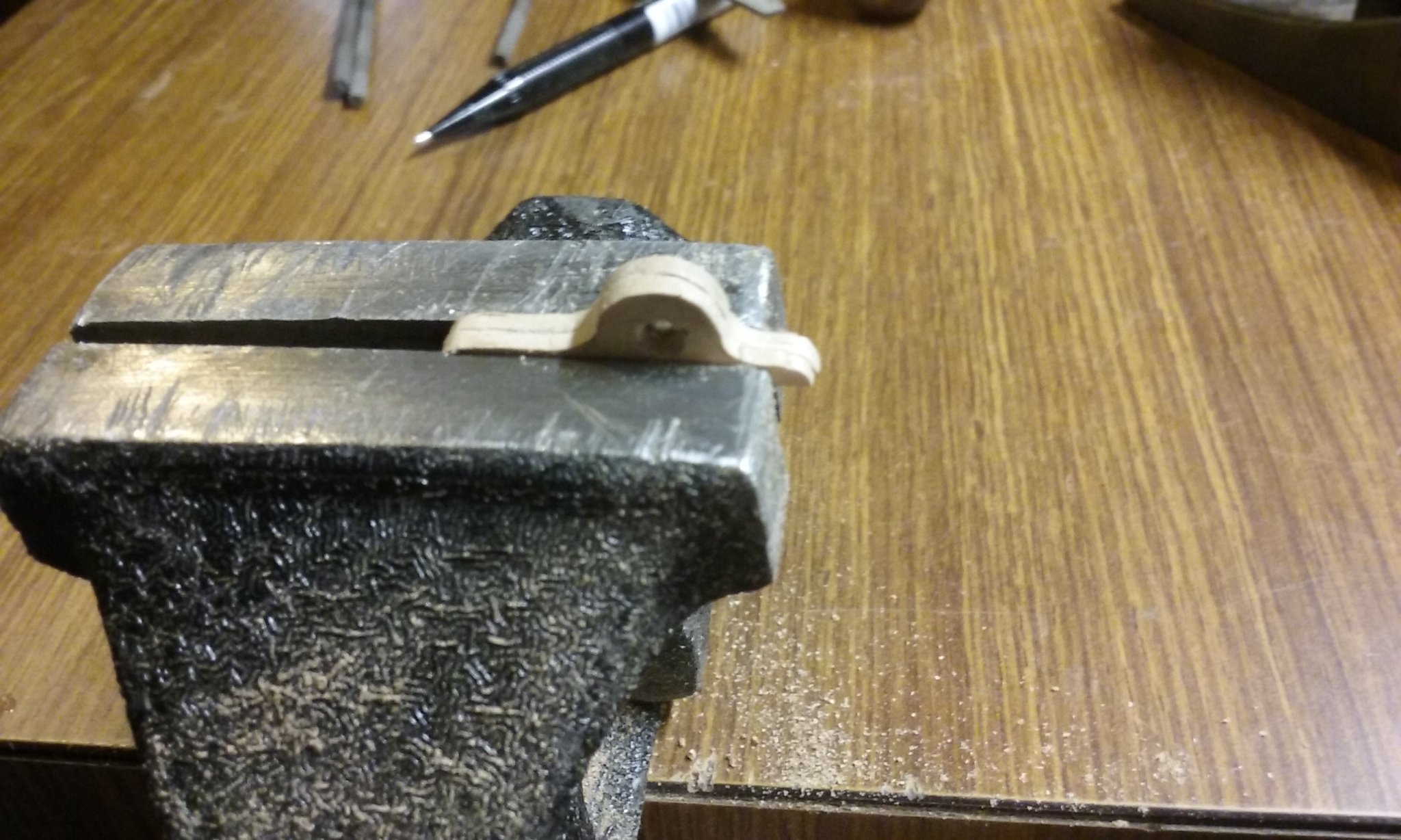
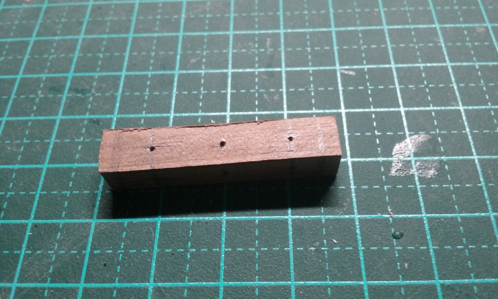
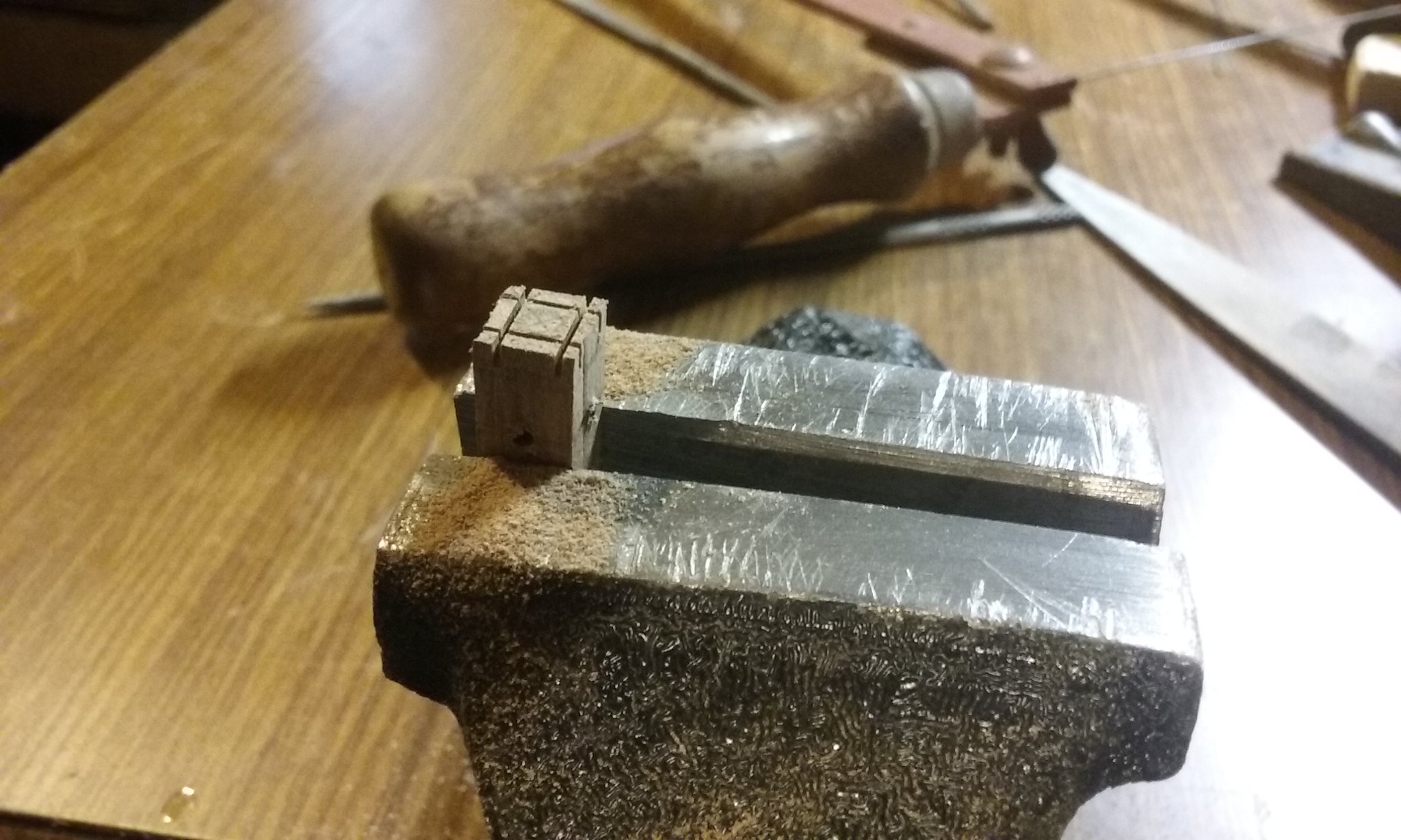
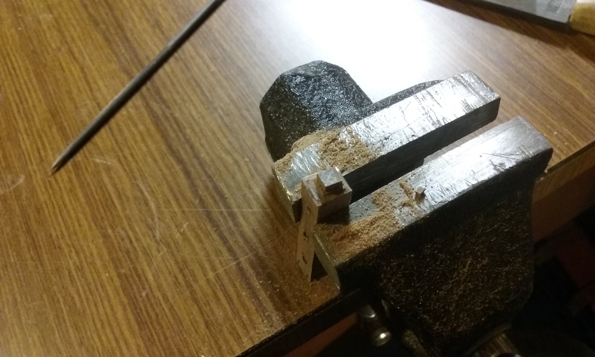
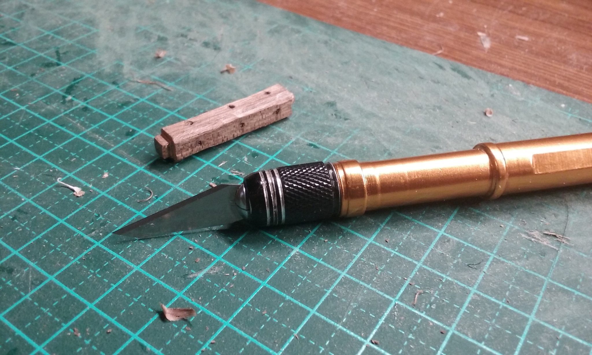
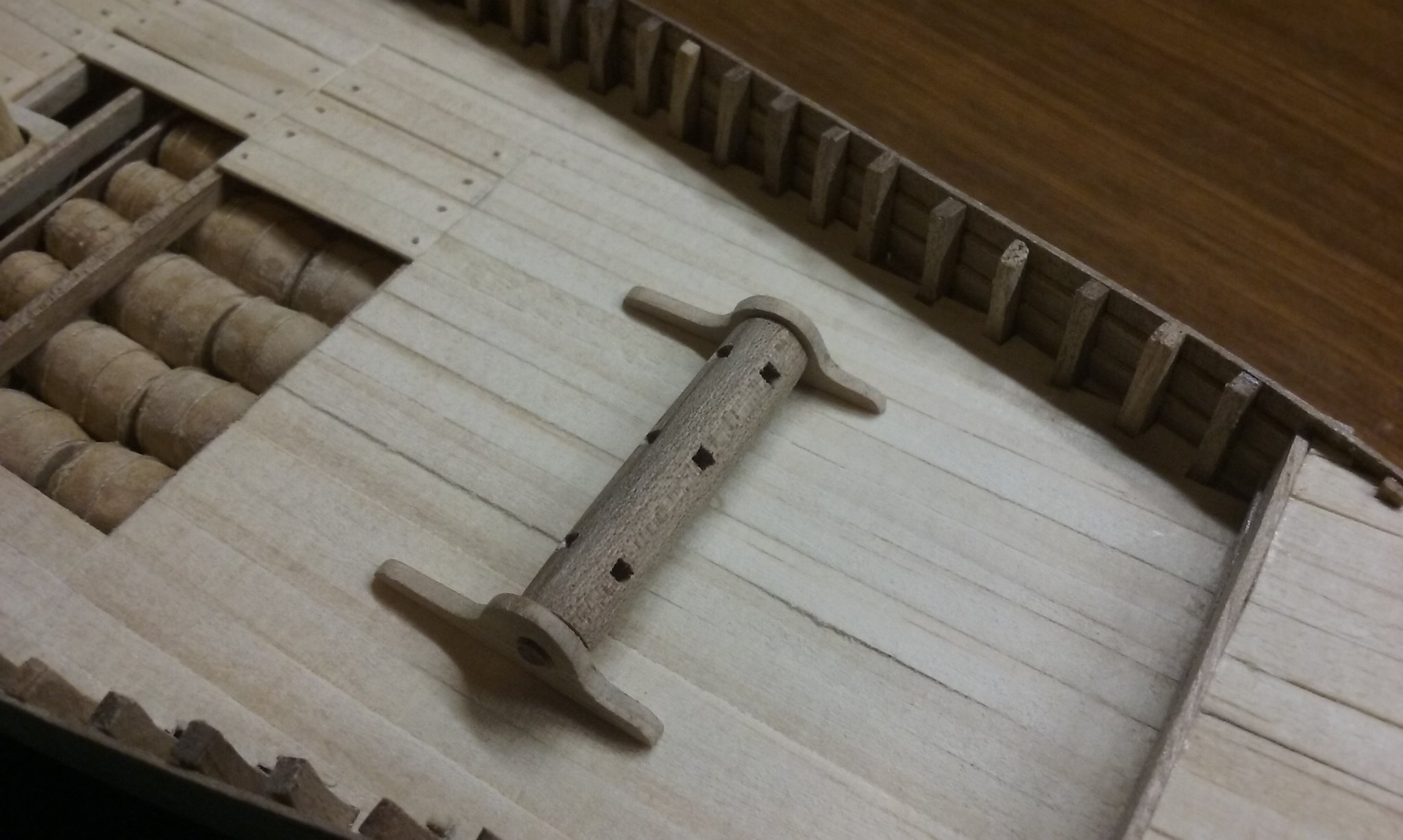
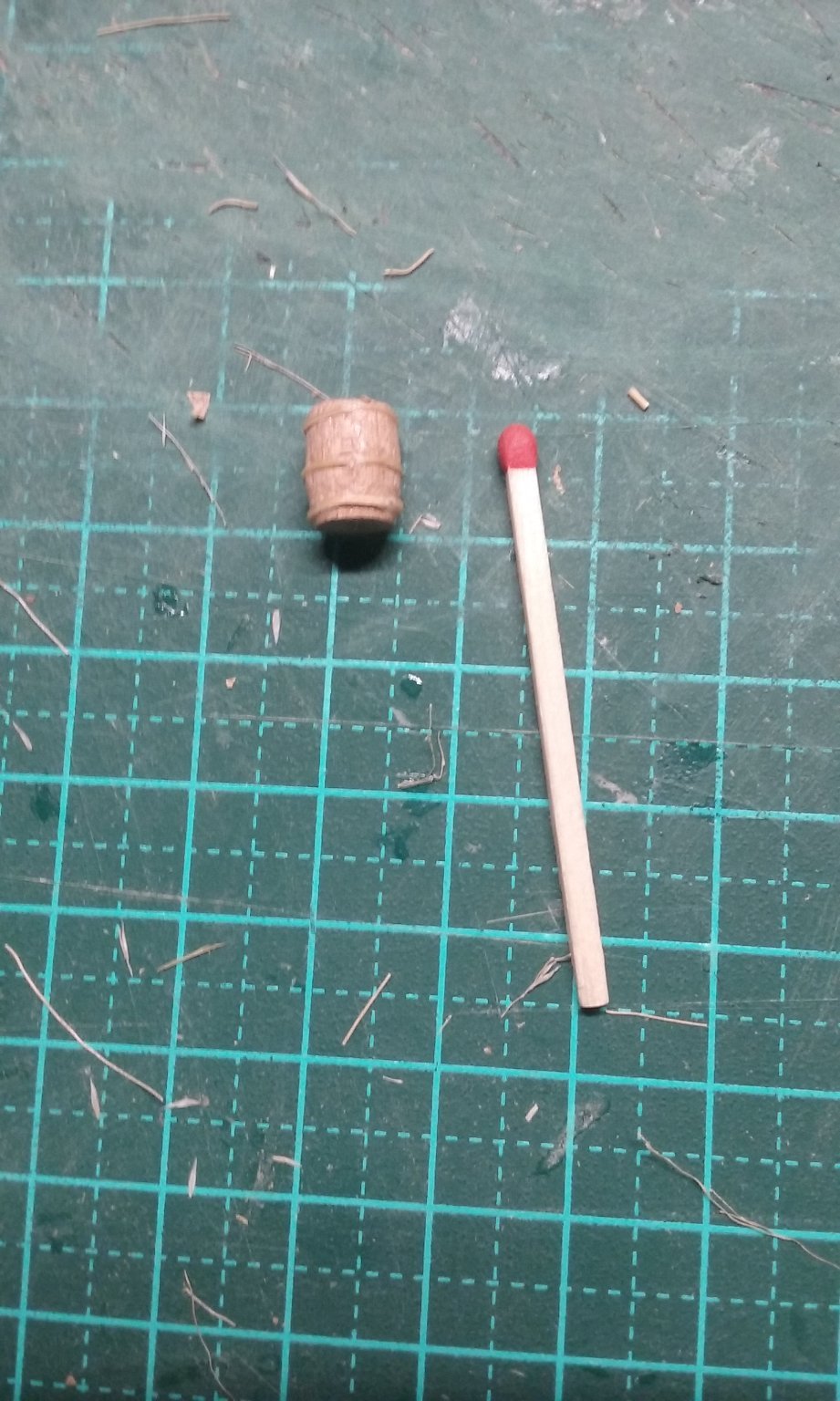
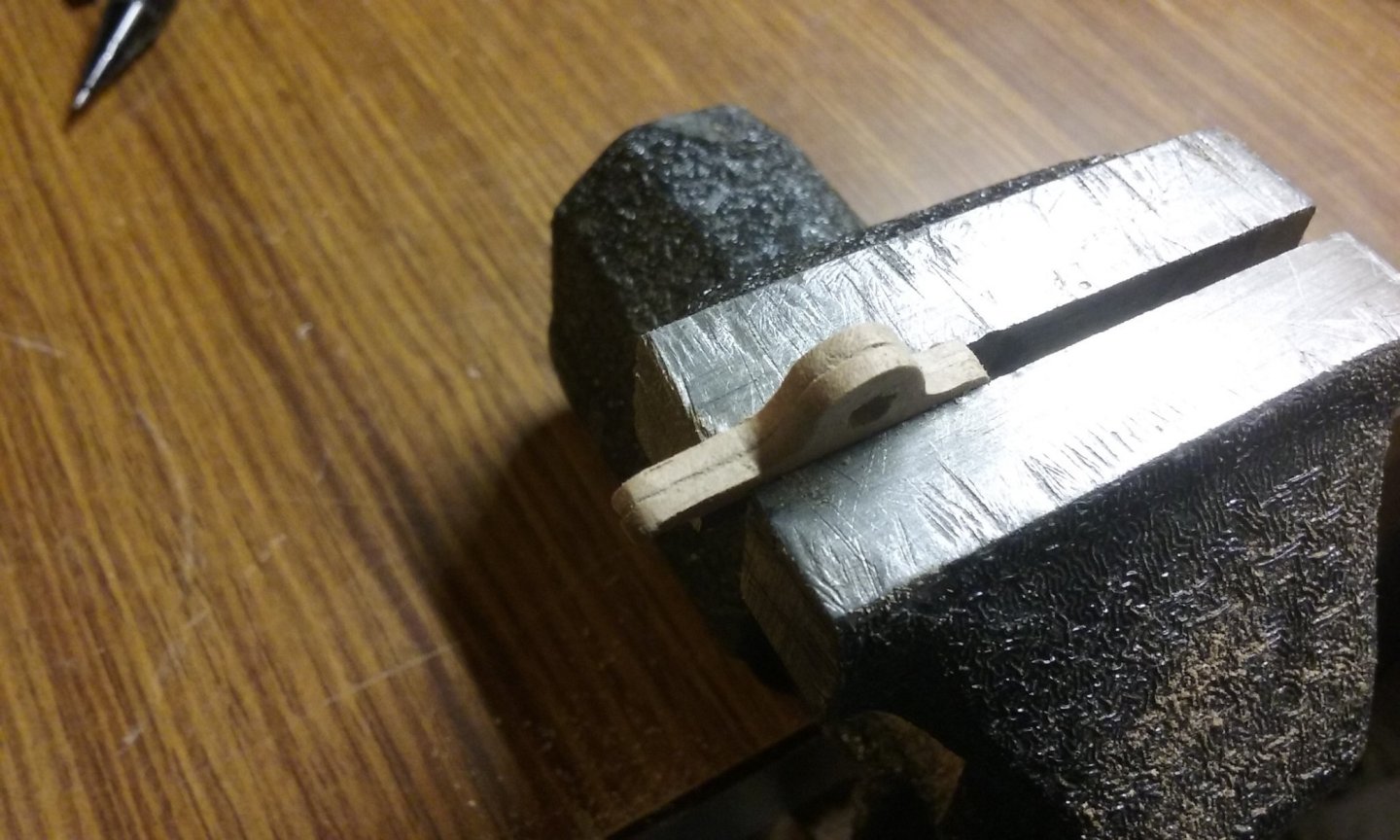
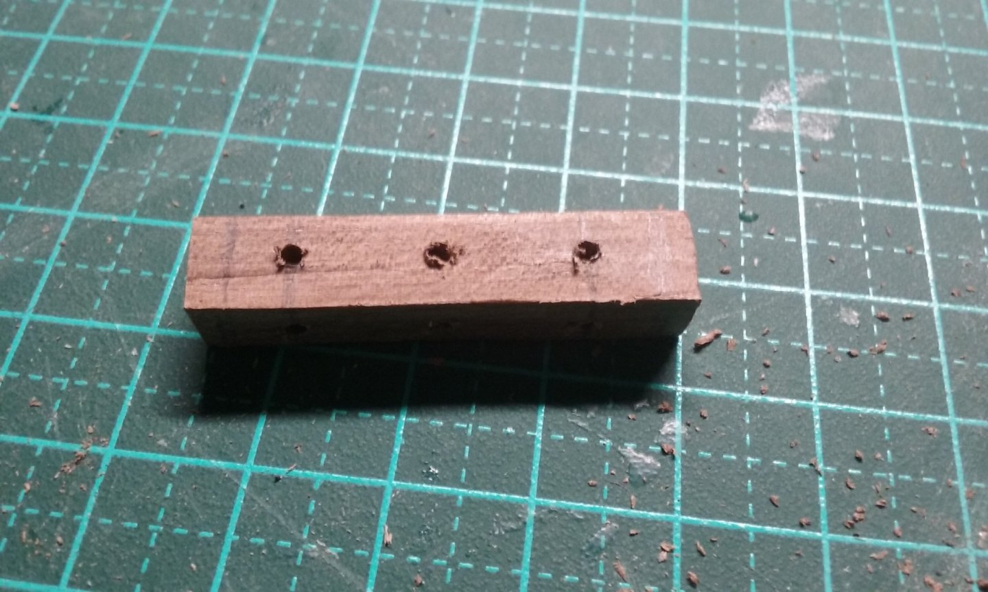
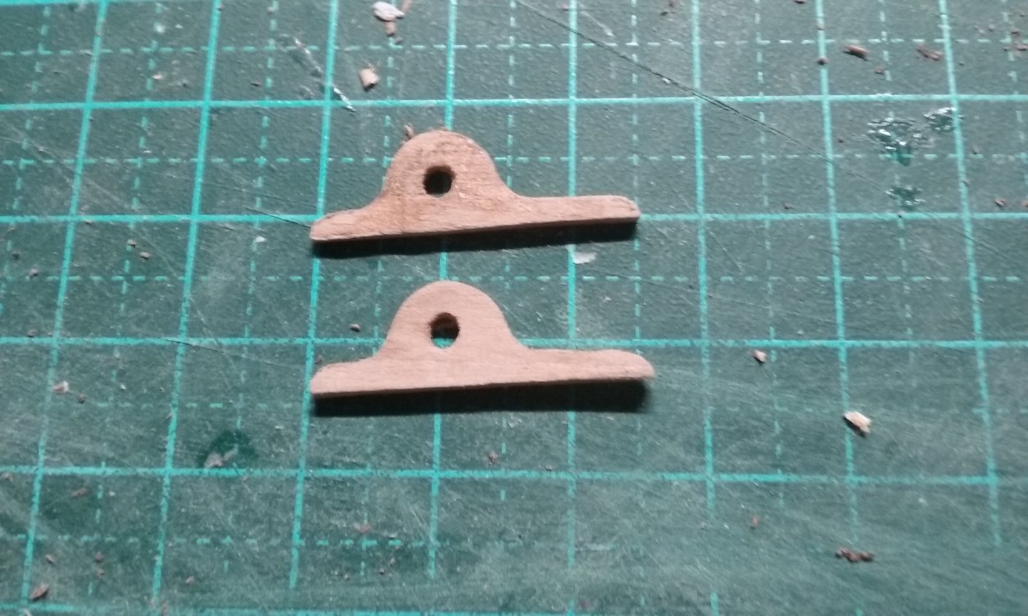
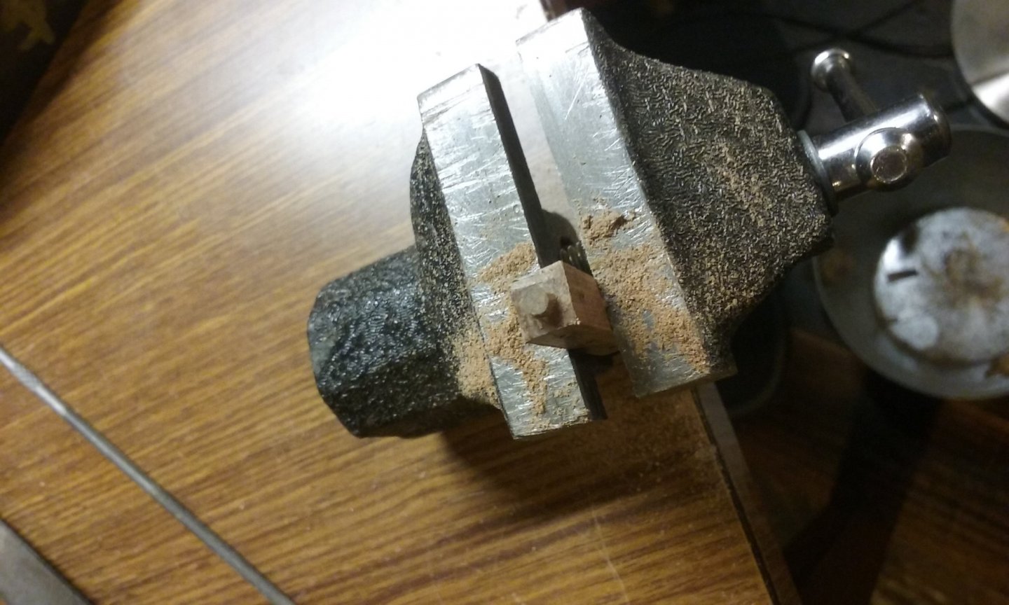
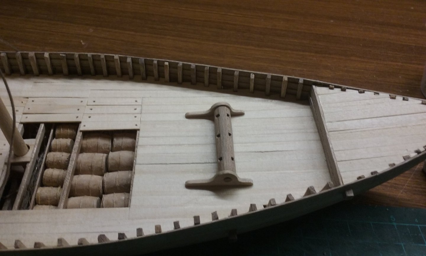
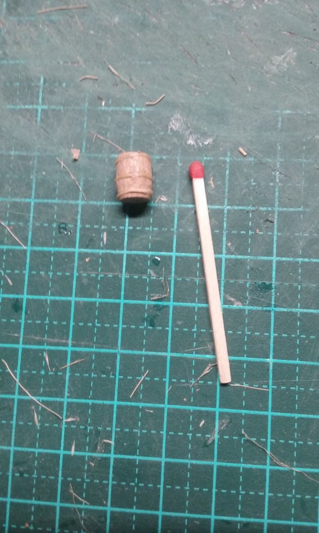
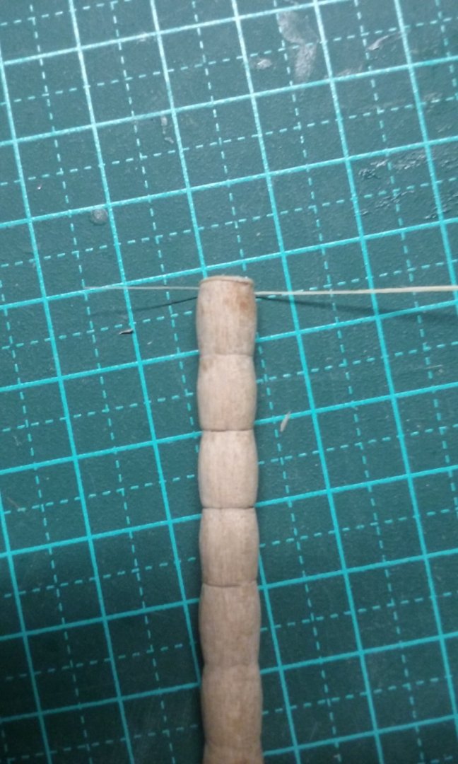
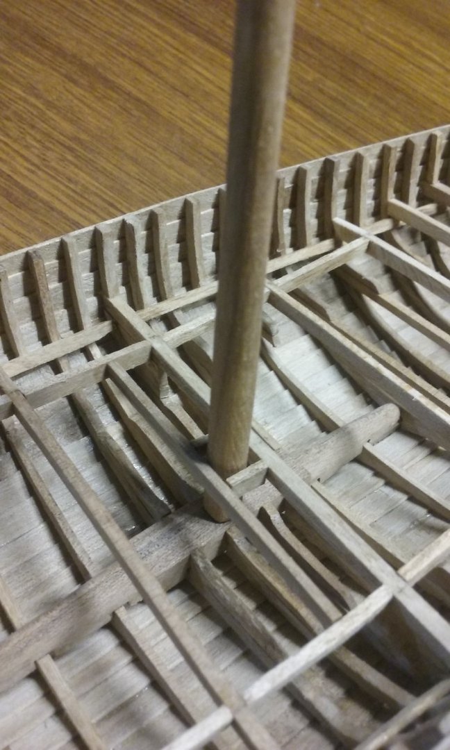
Here's the windlass - based on the ones from the Bremen cog, the Ijsselcog and the Kalmar ship. Making the two side pieces together so they're identical. I glued them together to put them in the vise and after finishing them I dissolved the glue with isopropanol. And the barrel. I figured it would be easiest to put the holes in while it was still square in section, and then round it off afterwards. I drilled tiny pilot holes halfway in from each side so they would line up and join into a single through-hole perpendicular to the barrel. Then enlarged the holes. Cutting the "axles" into the barrel. Firstly square section: Trimmed: Changing the barrel from square section to octagonal. Then axle rounded off: Barrel rounded off, assembled with side pieces and dry fitted. Note the holes for the bars have been squared off, in line with the ones found in archaeology. Round hole for the mast (dunno what it's called). Bars added. I had to unglue the barrel from the side pieces and rotate it, to get the bars in the right orientation to be reached by the crewmen. The windlass with a crewman for comparison. This made it clear that the bars were much too thick at the "handle" end, so I tapered them. Next - the castles! Steven


- 327 replies
-
- 16
-
-
This is such a good build. I really enjoy the beautiful detail you put into it, and the extra touches, like the rust on the anchor. Wonderful work. Steven
-
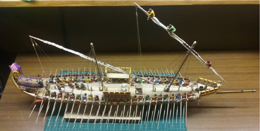
Thanks, but after doing the crewmen for the dromon - - carving 8 figures is going to be a bit of a doddle! Steven
-
Thanks everybody for the likes and comments. The barrels? Yes I carved them, though I should probably have used my poor man's lathe (electric drill). Or do you mean the crewmen? Yes, I carved them too. Steven
-
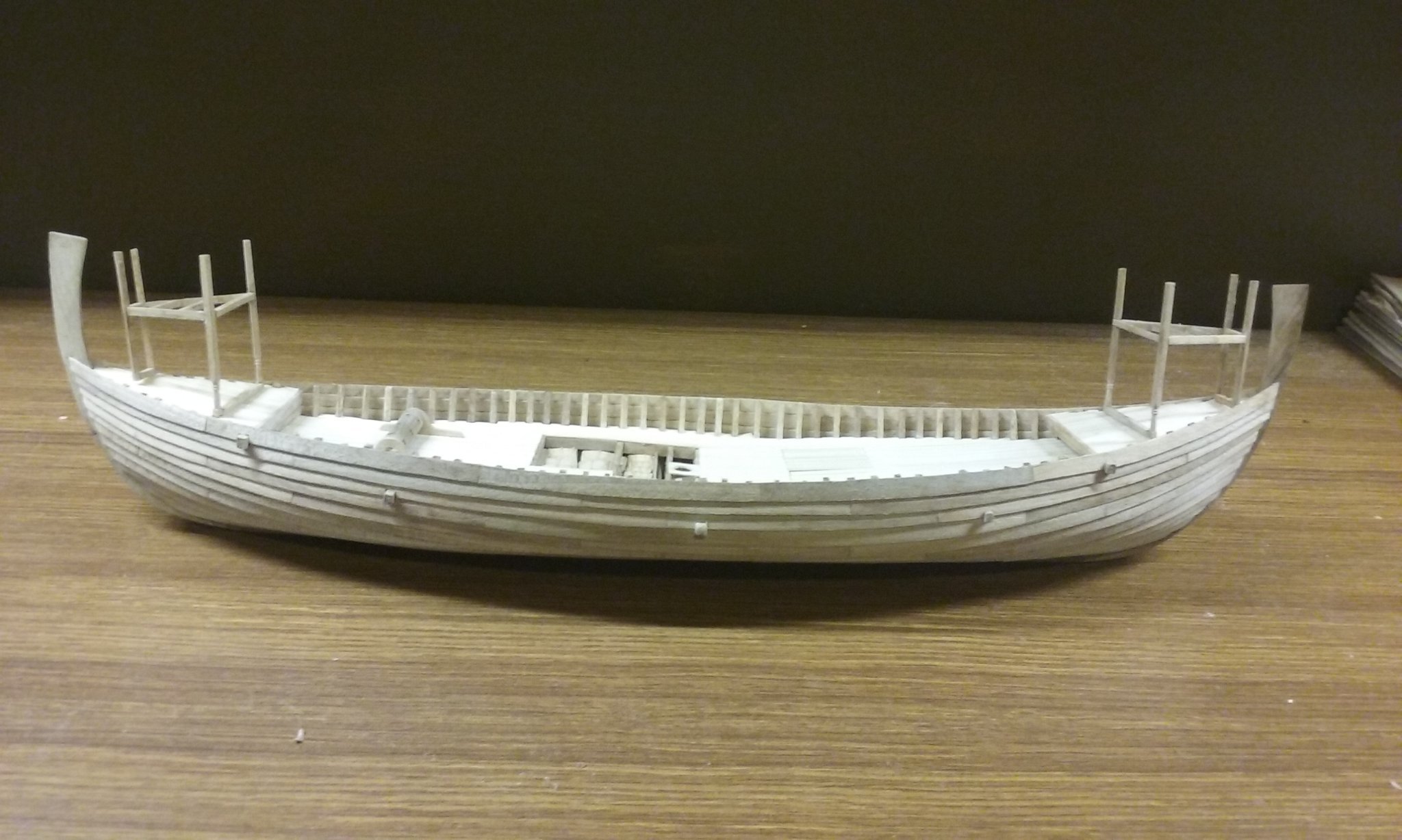
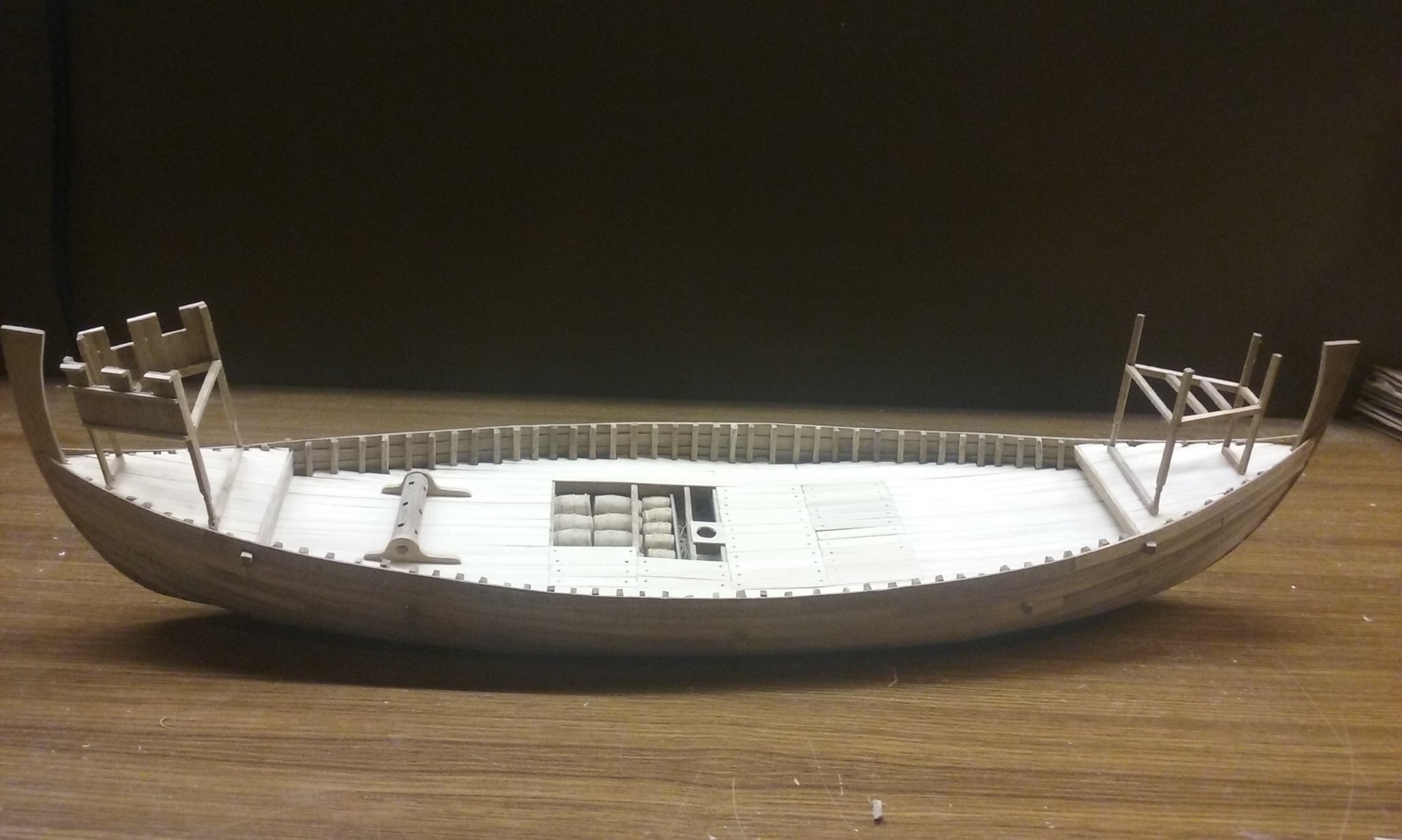
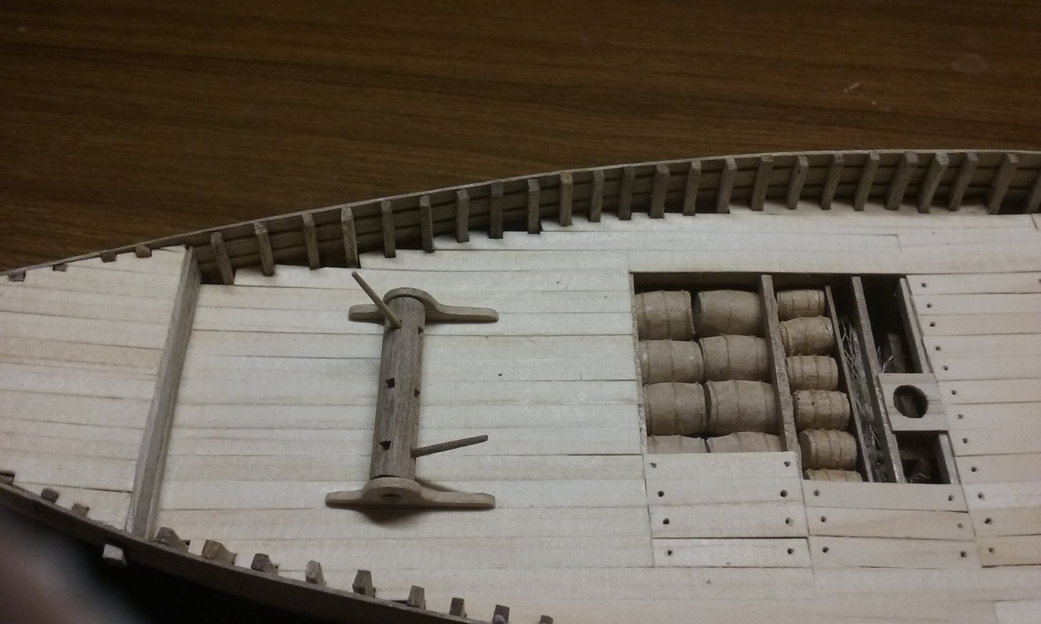
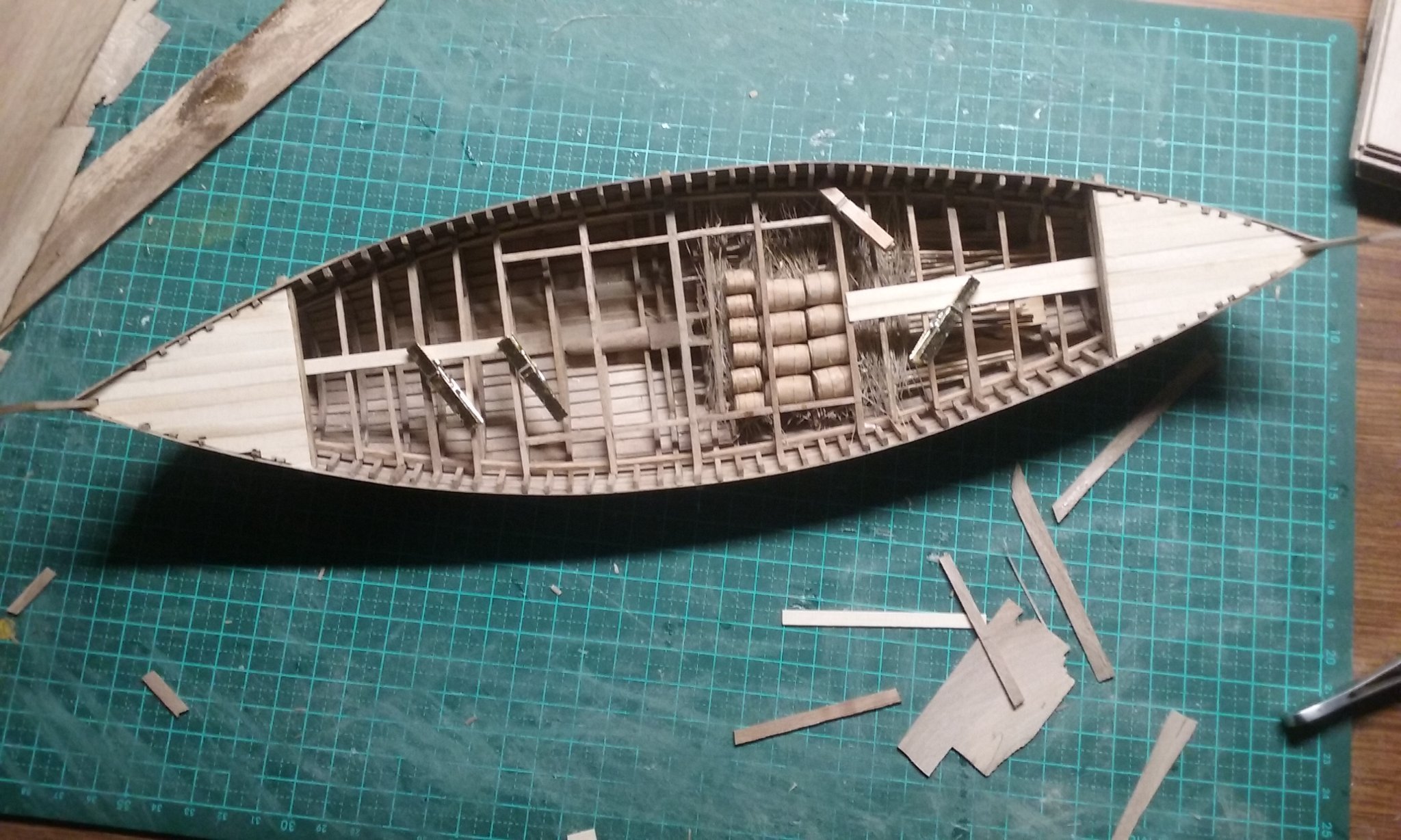
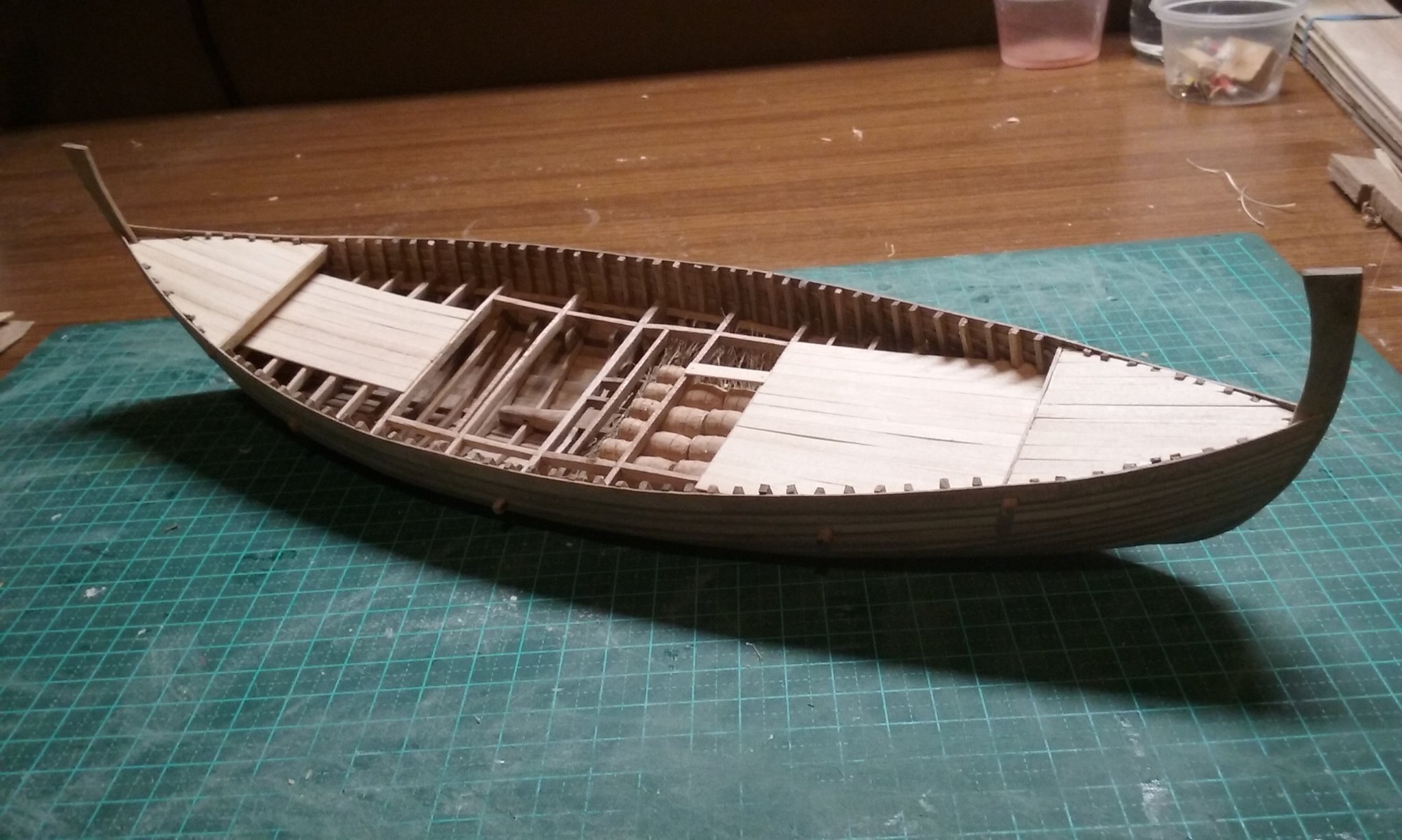
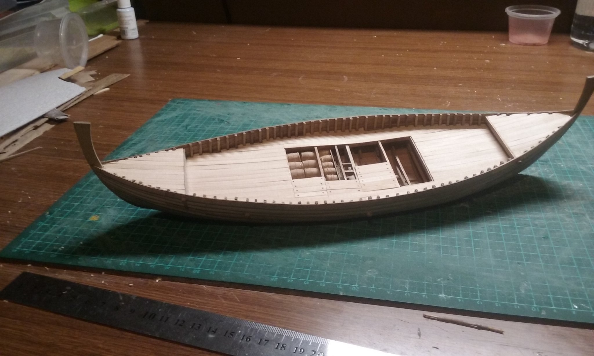
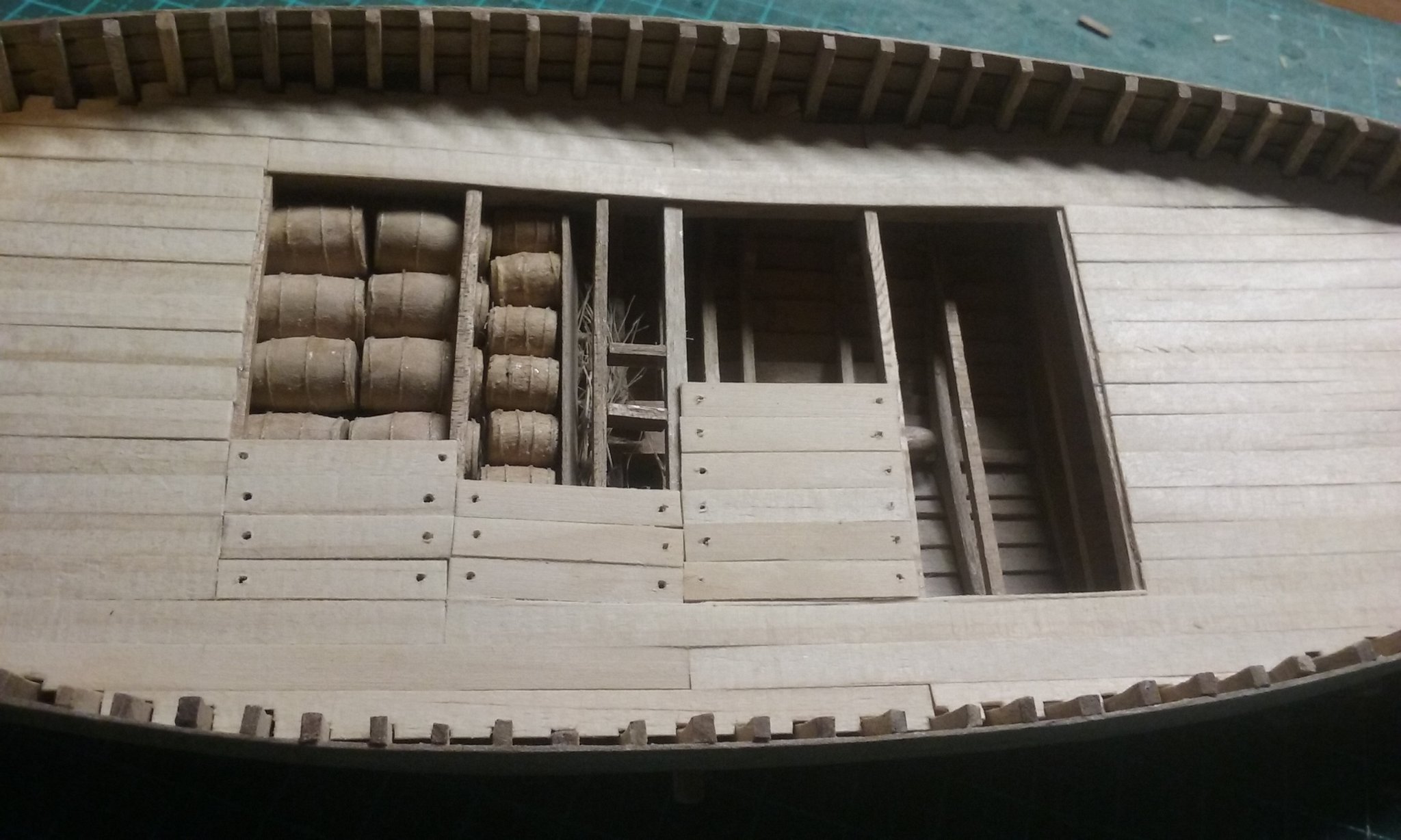
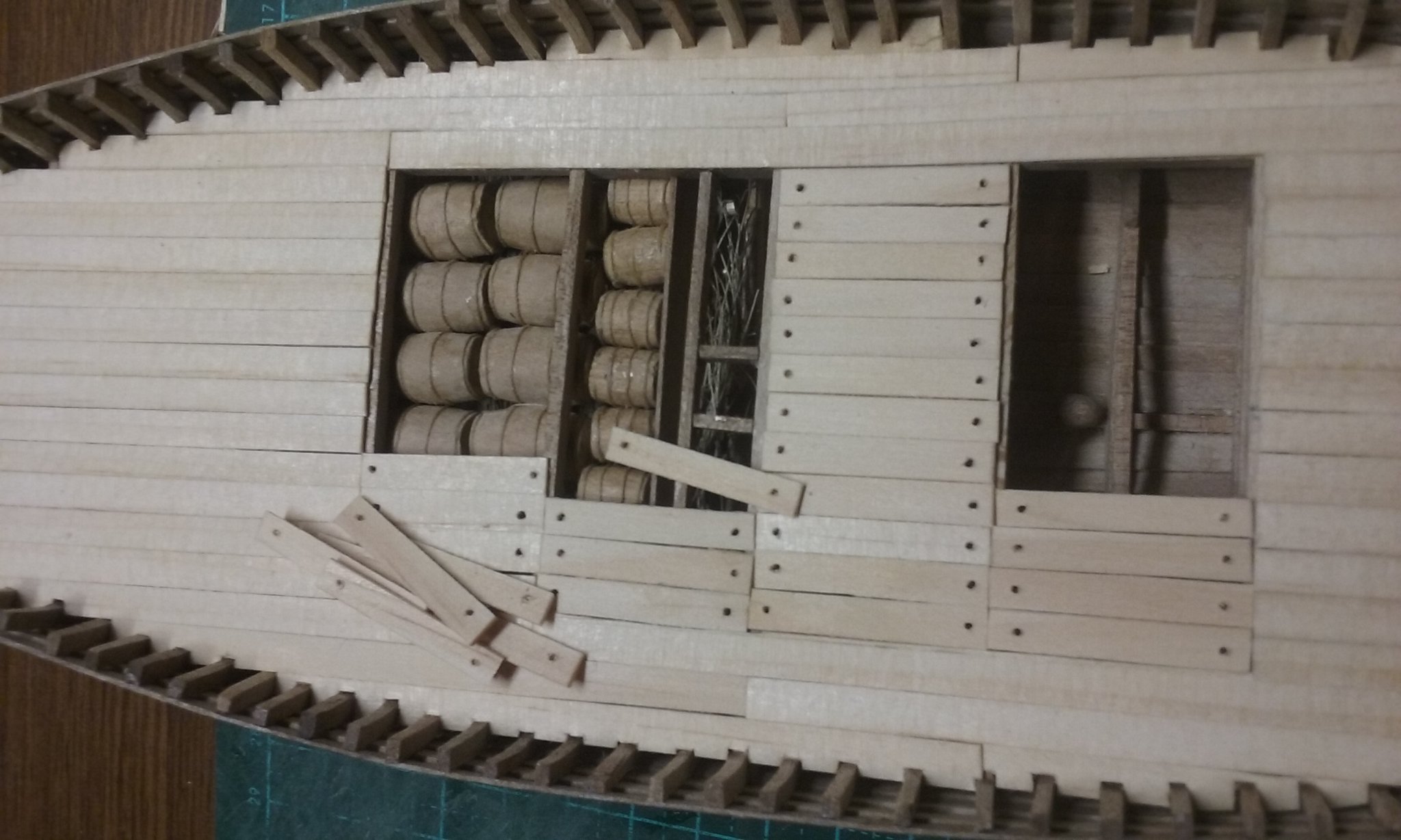
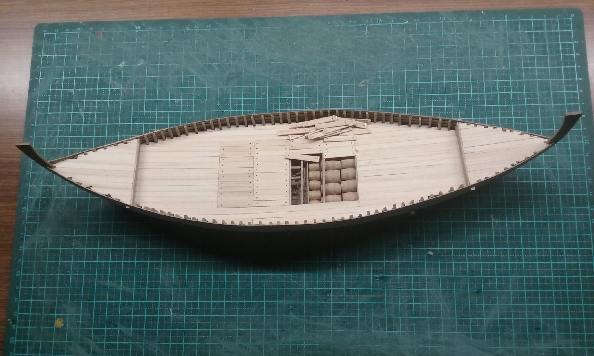
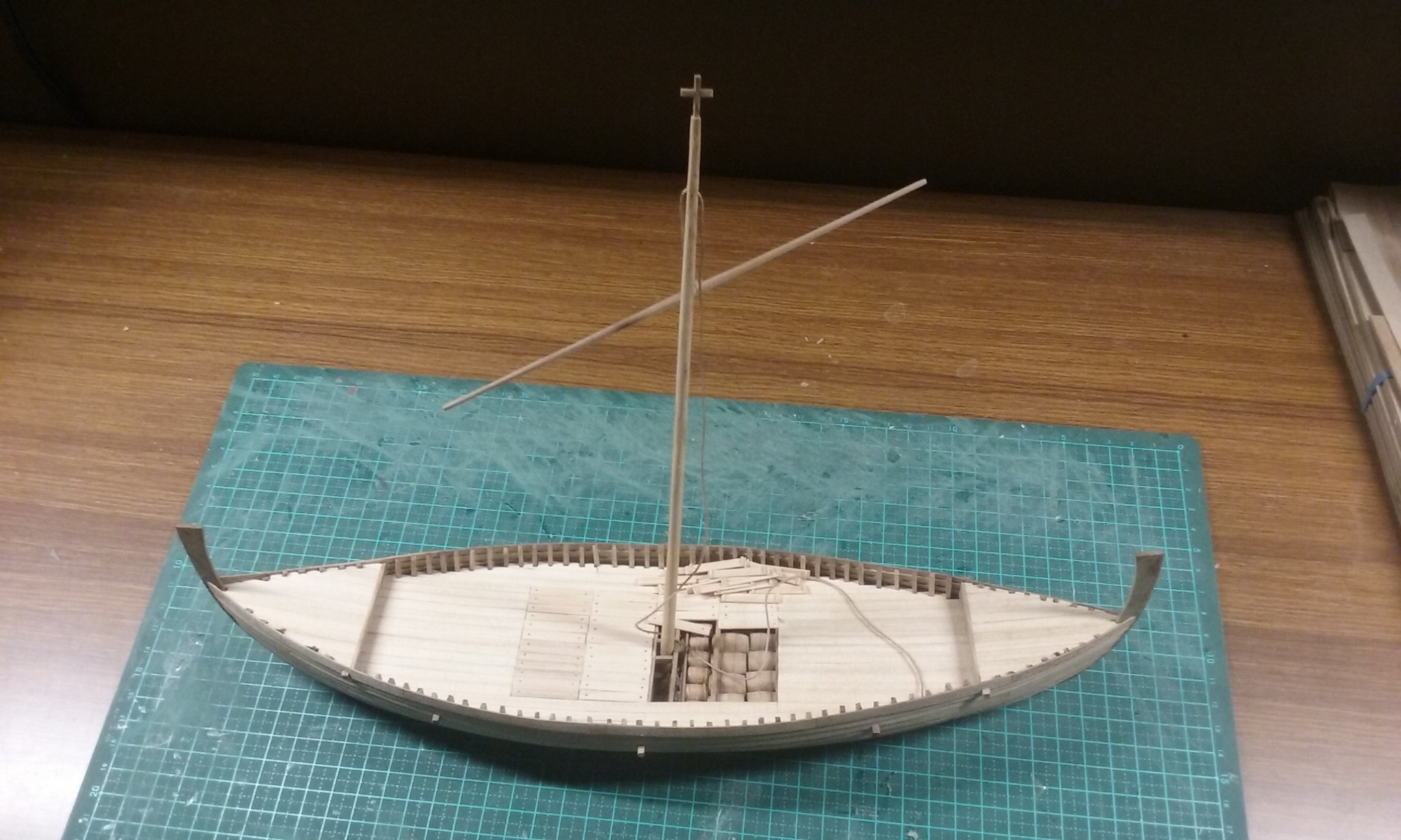
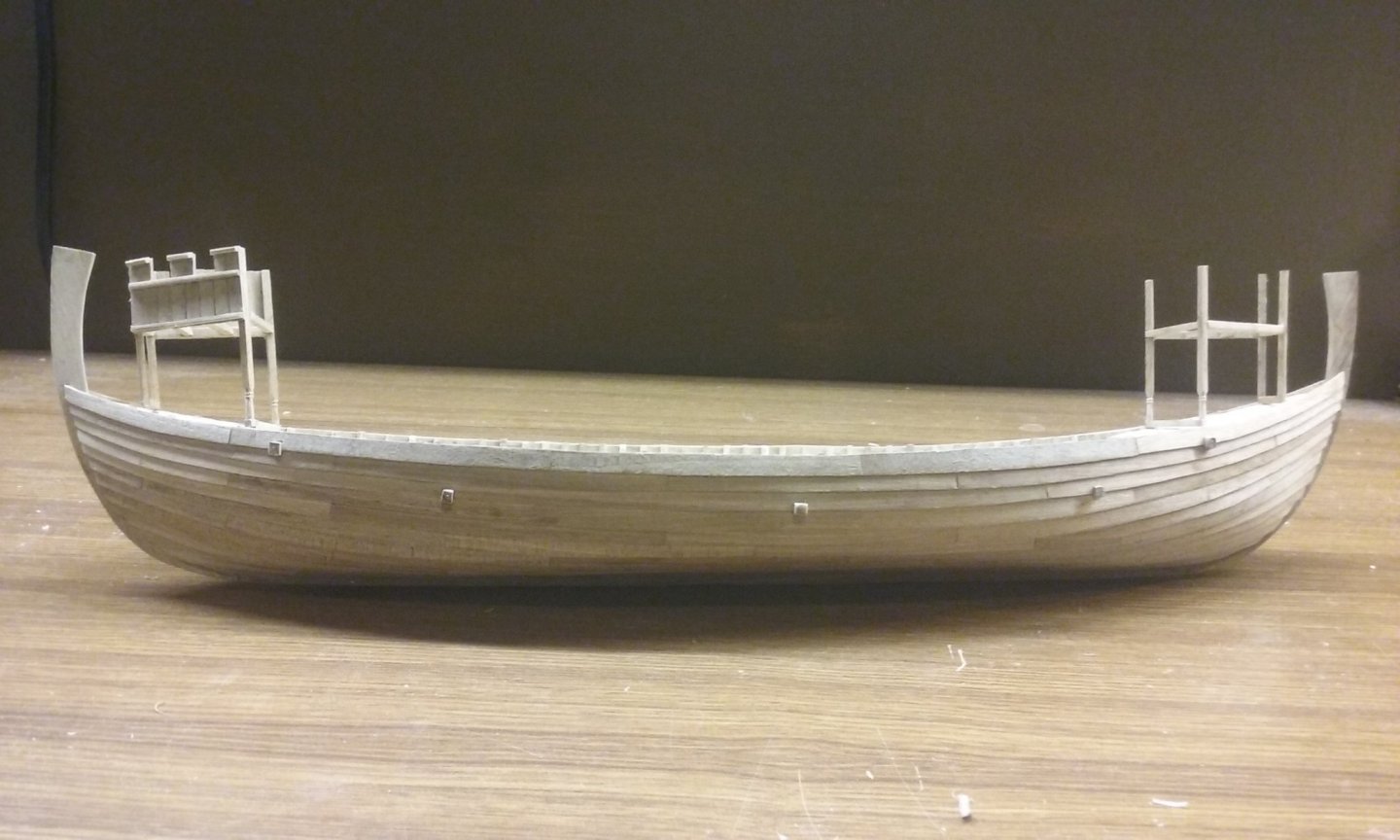
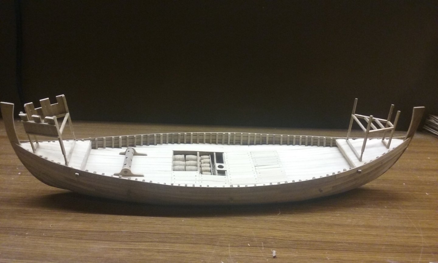
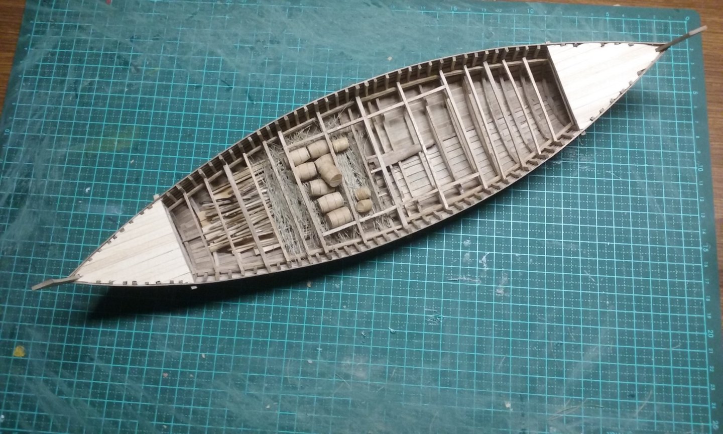
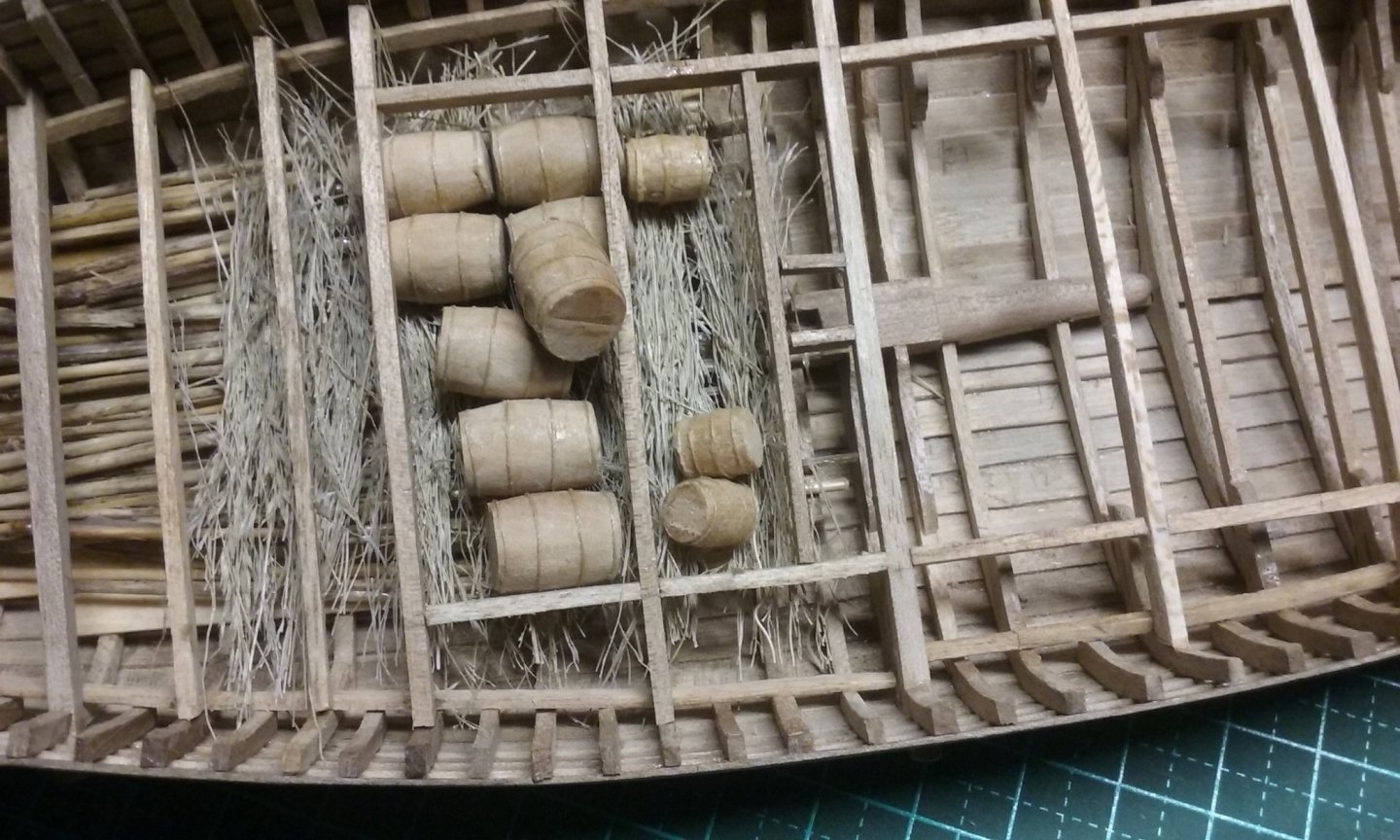
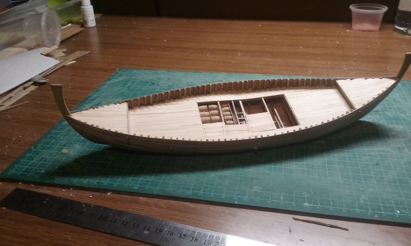
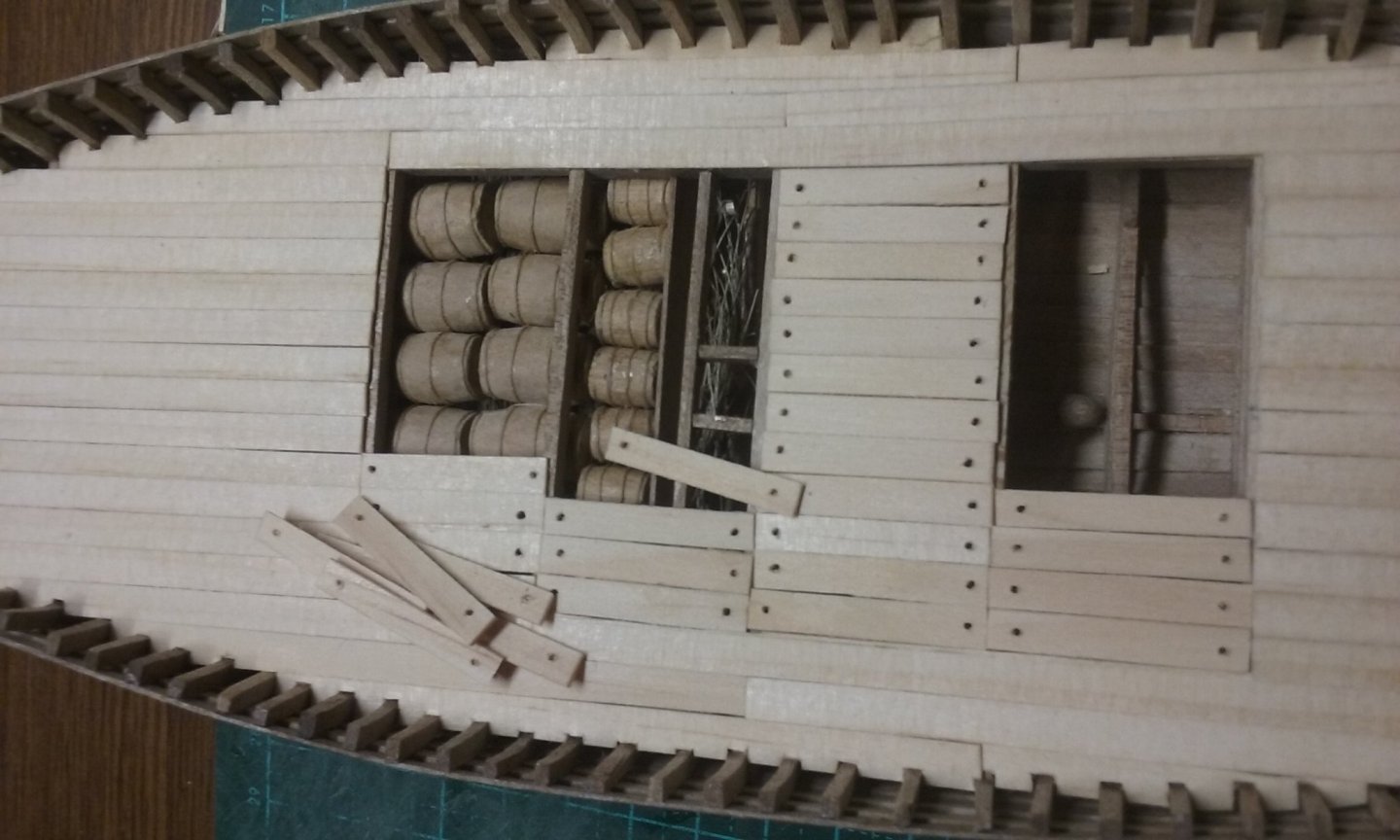
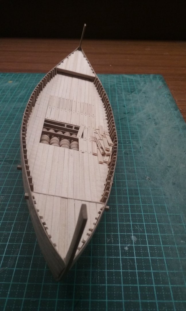
Cargo finished - at least the bit that will be visible. Both large and small barrels. Cargo arranged in position. In the real world they'd have been wedged tightly together - with wedges. And a start on the main decking. Main deck planking complete. And starting to add the removable planks to go above the hold. All the removable planks glued in place except the ones left off to show the cargo, stacked off to one side. I think I'll make an extra crewman and show him putting the last of them in place. And the mast and yard dry fitted to give an idea of proportions. Next to make the windlass, then the steering oar and the castles for the bow and stern. Coming along nicely. Steven


- 327 replies
-
- 19
-
-
Welcome from sunny Ballarat! Steven
-
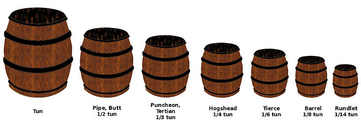
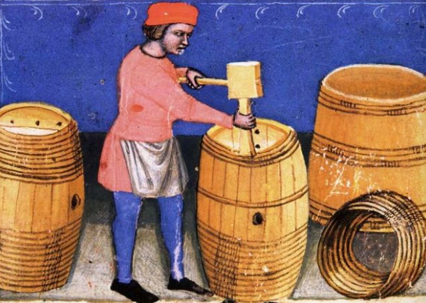
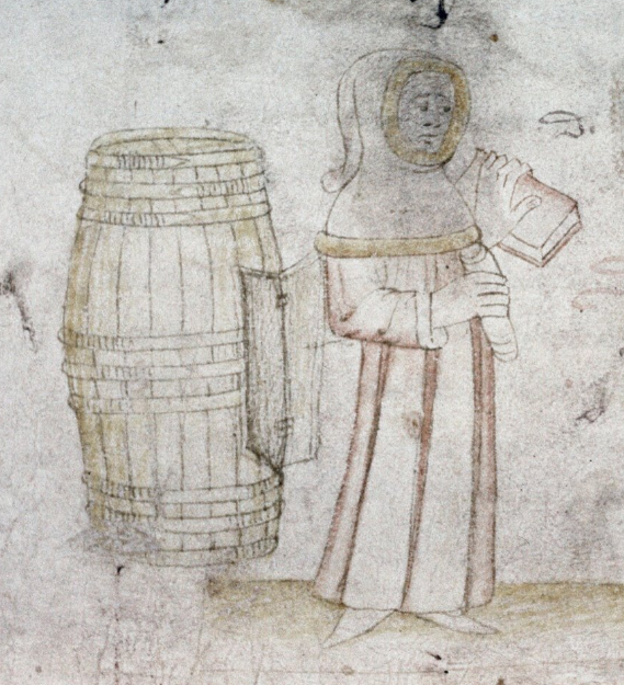
That's right. Add to that the fact that in this period it was probably even less standardised - they probably made barrels "the right size", whatever that may have been at the time - see the pictures above - quite a wide variation. So I'm not going to get too fussed. But I do like the idea of two sizes of barrel on the ship. Steven
-
OK. I've done a bit of research. Certainly there is a wide range of barrel sizes - https://en.wikipedia.org/wiki/English_wine_cask_units But if you look at mediaeval illustrations, particularly of wine barrels, they generally seem to have been pretty big - Maybe I'll go with the idea of different sized barrels. Thanks for the suggestion, Druxey and Mark. Steven
- 327 replies
-
- 10
-
-
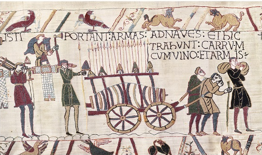
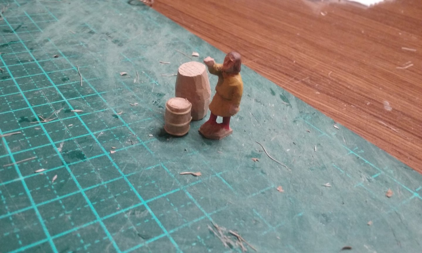
Thanks for the likes and comments. Chuck, I thought about the barrels for quite a while and even researched the size of a tun (though it only gave me the volume rather than height and diameter). However, barrels come in all kinds of sizes, so I went for something that could be handled relatively easily by one or two people. On the other hand, really big barrels do go back a fair way - see this excerpt from the late 11th century Bayeux Tapestry, of a barrel that's been carried across the English Channel in what is effectively a Viking ship, for the Norman soldiers invading England in 1066. Translation "These [men] carry arms to the ships, and here they haul the wagon with wine and arms" [Edit] Just roughed out a larger barrel - not a full tun - it would be too big to go in the low headroom of the hold - but quite a bit bigger. Here's the original size. And here it is with the new one, in the ship and against a person. Maybe I'll go with the bigger size after all - one advantage is that there would be fewer to make. Just as well I posted now, rather than after I'd made all the smaller ones . . . [/Edit] Steven
- 327 replies
-
- 13
-
-
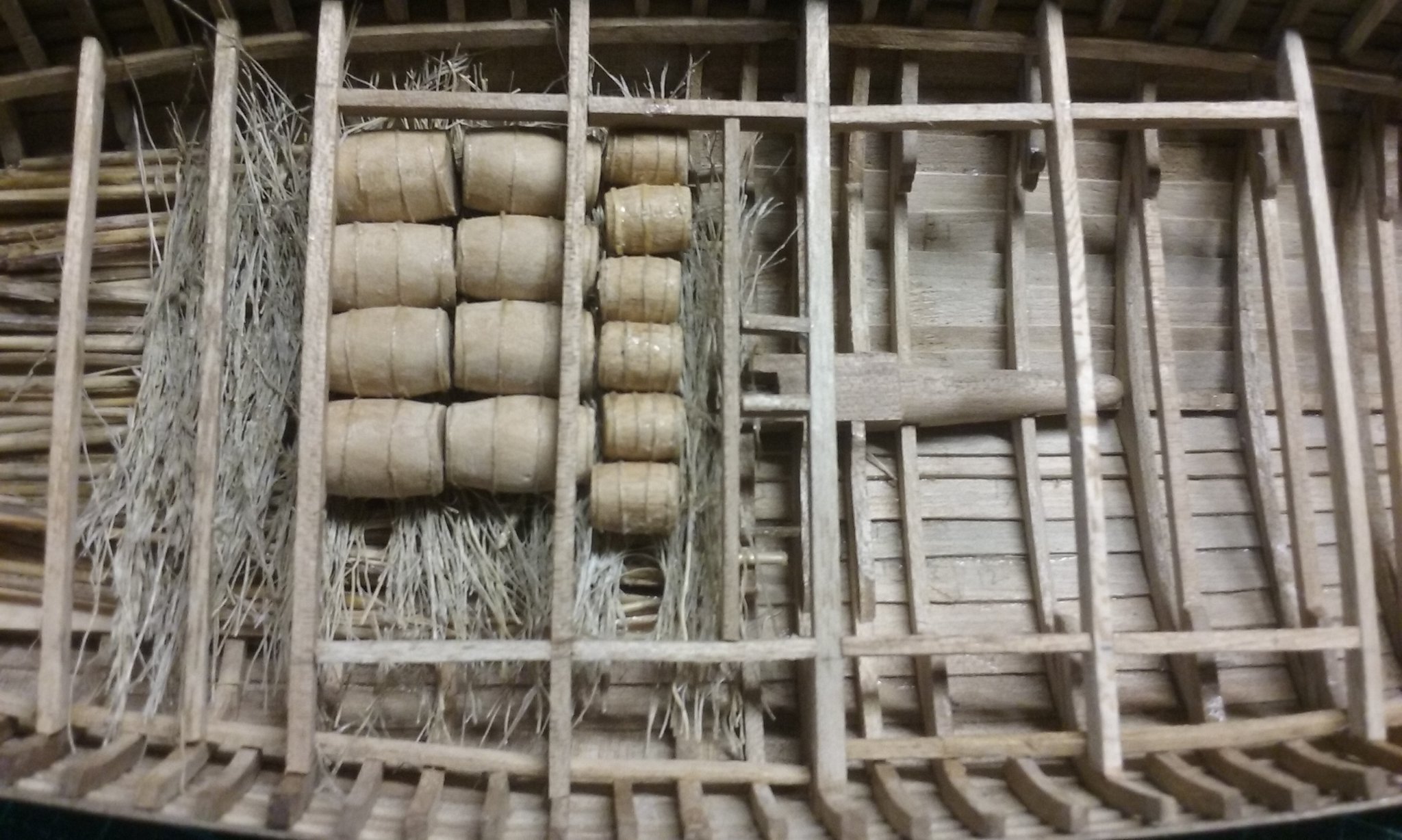
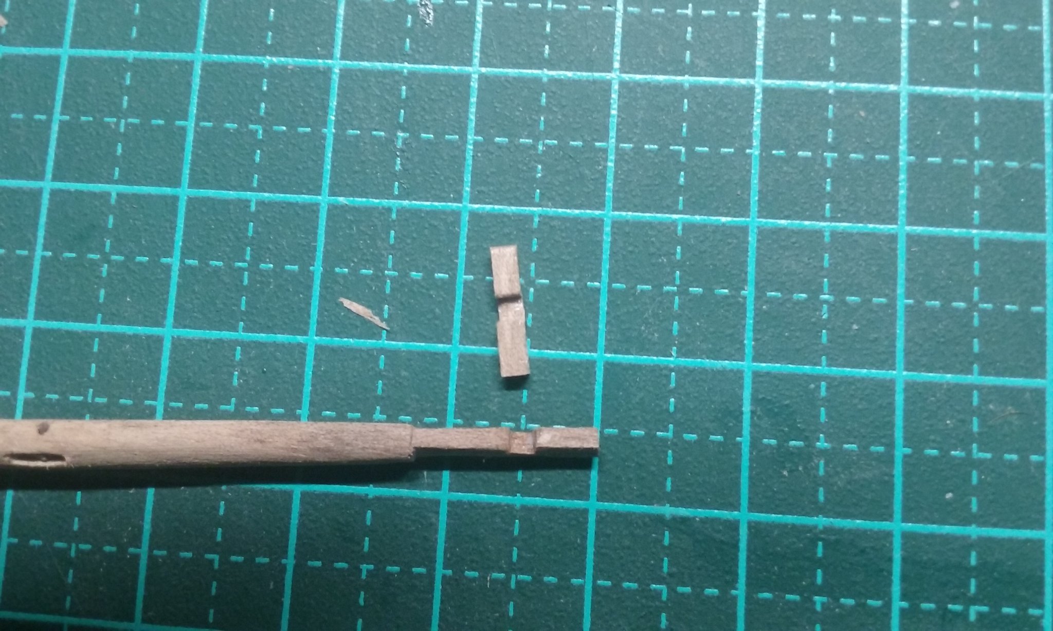
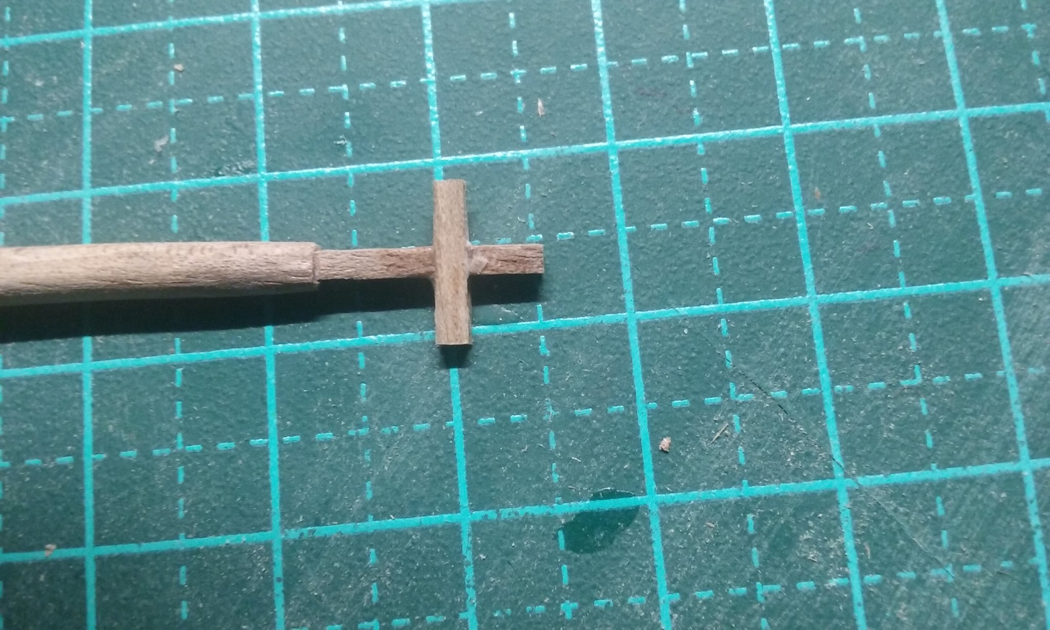
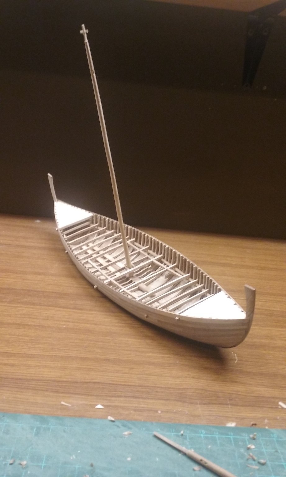
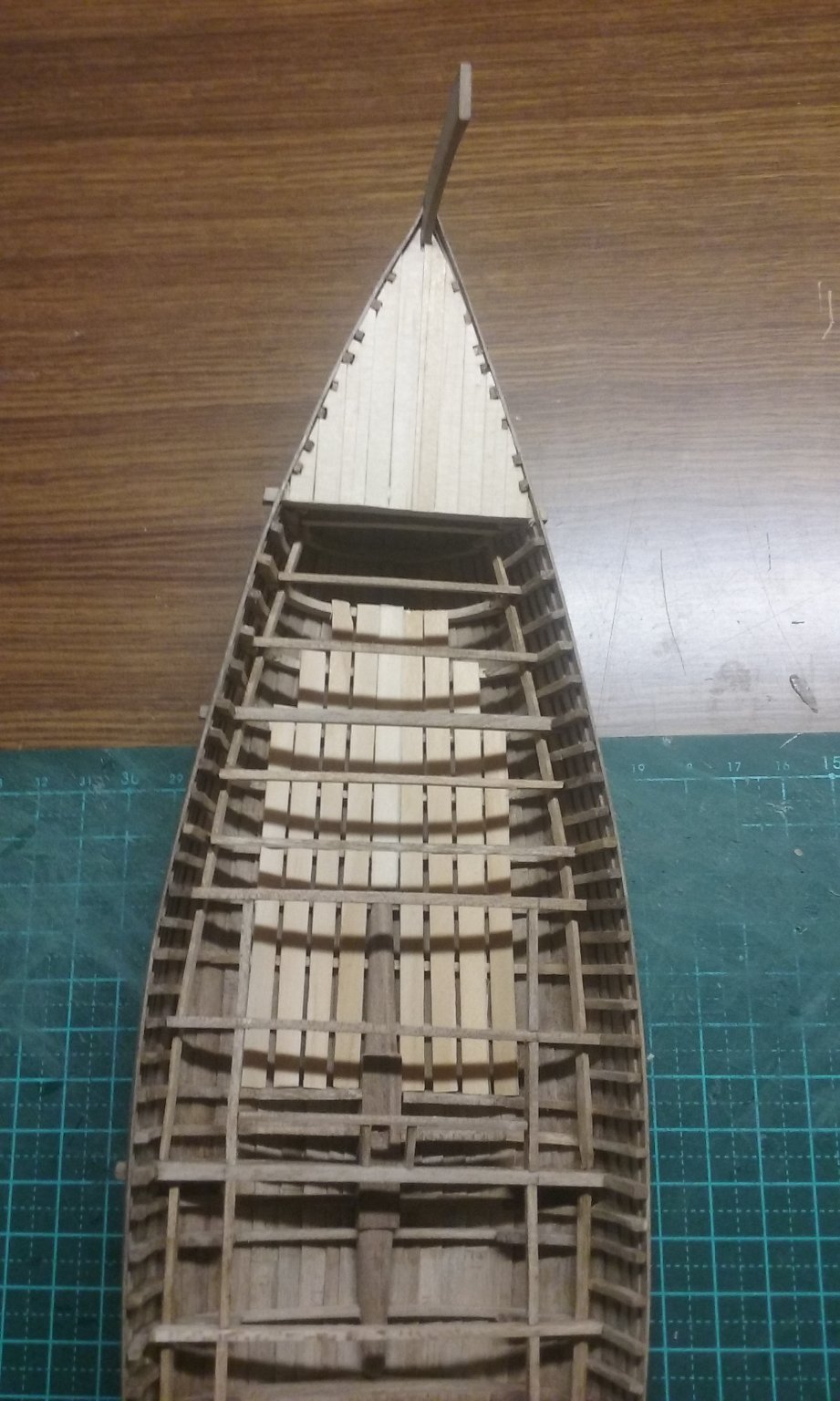
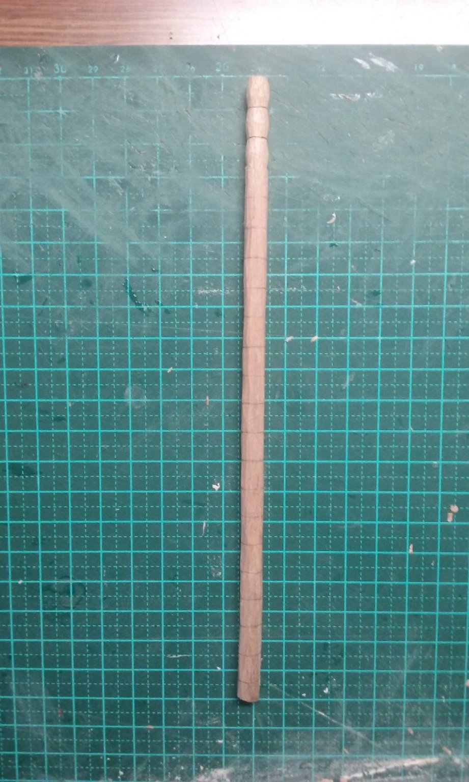
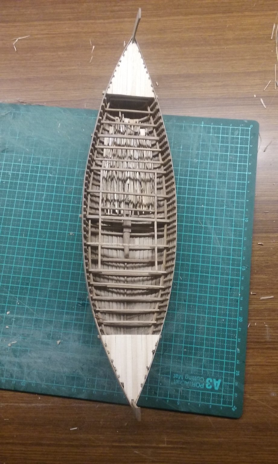
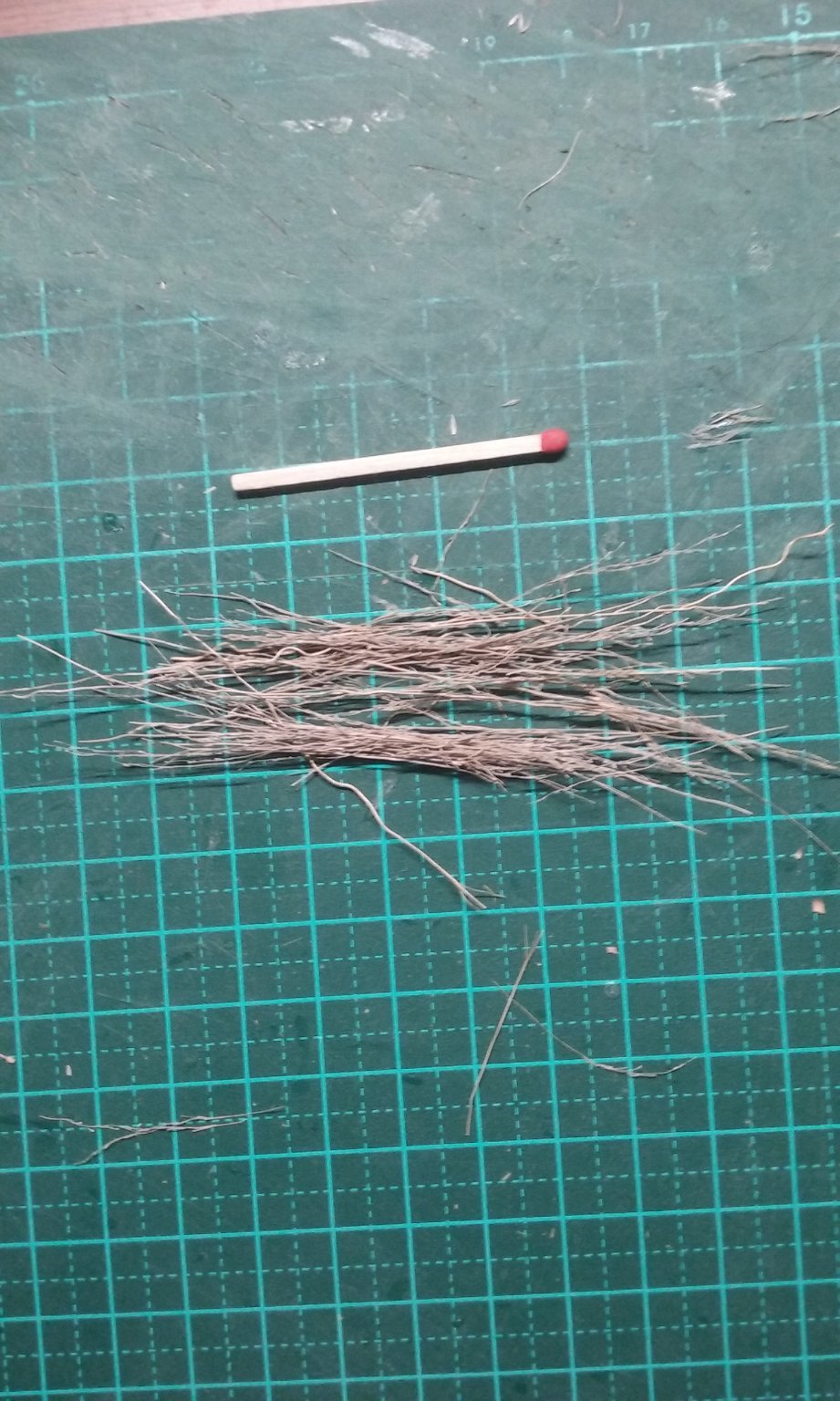
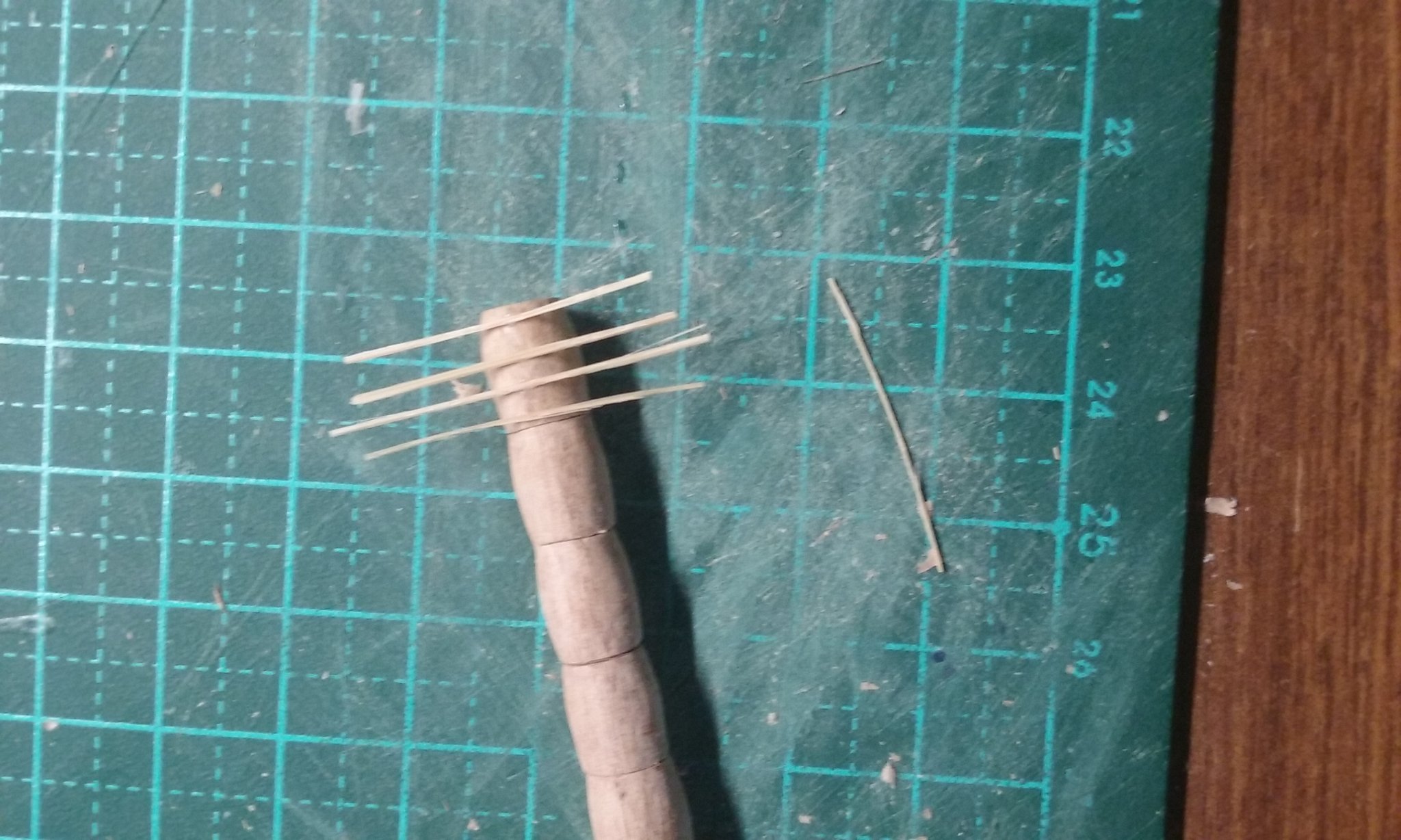
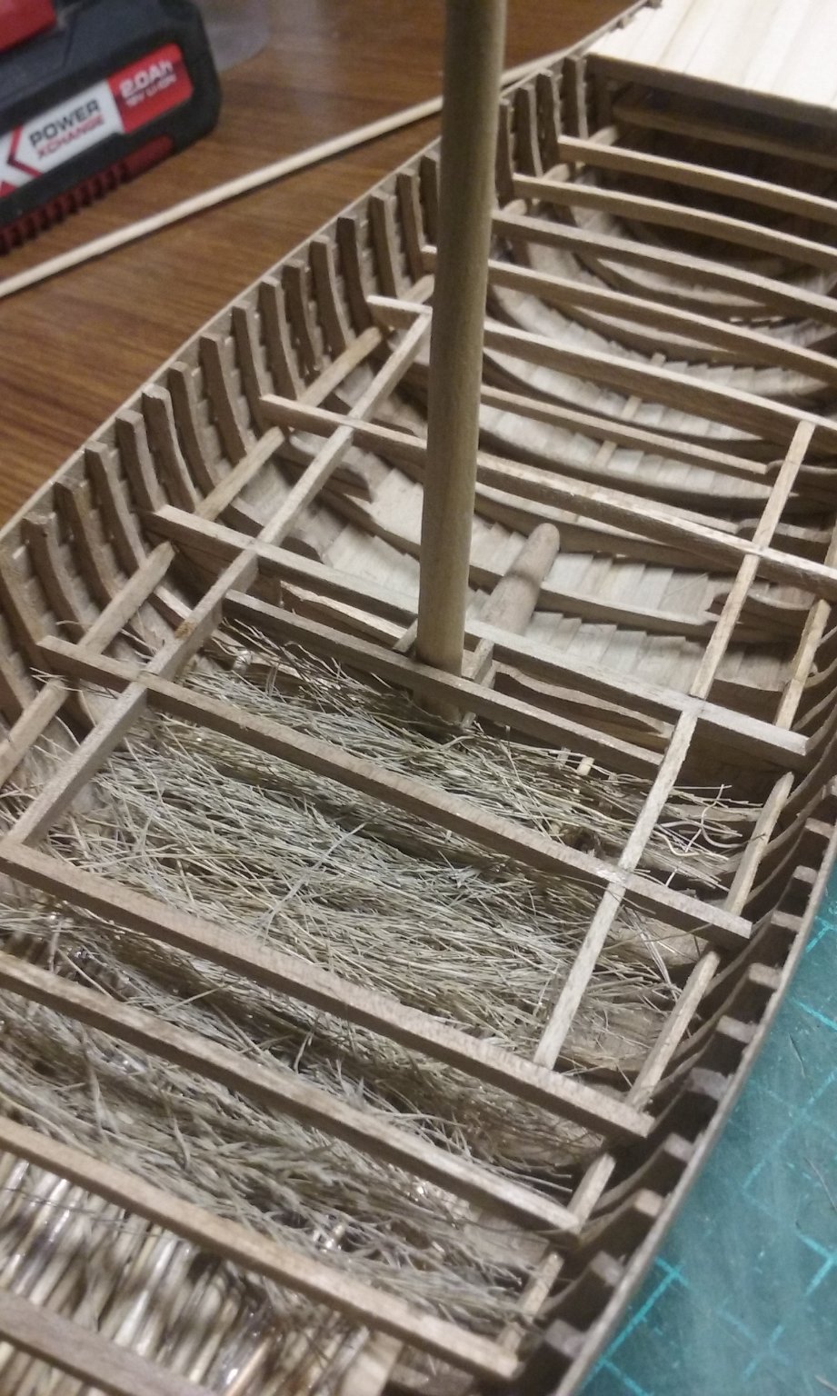
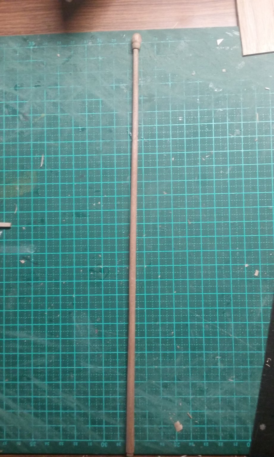
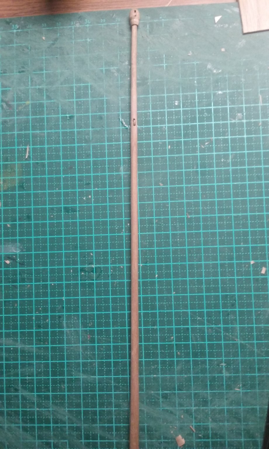
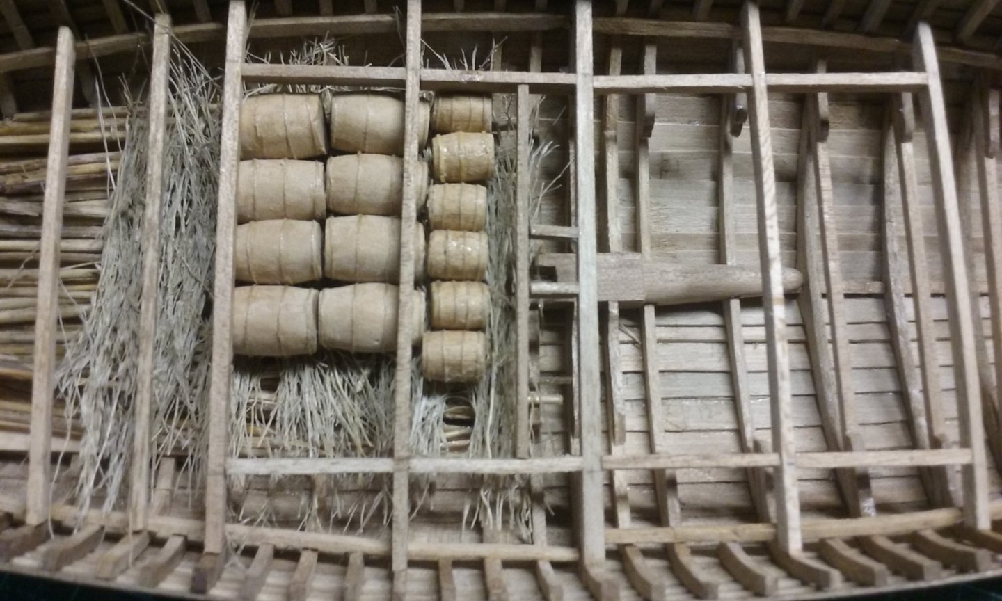
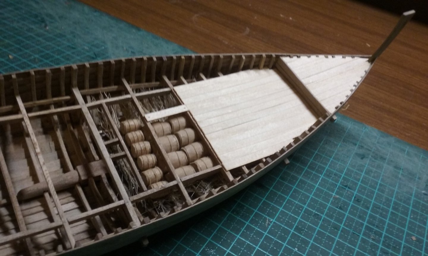
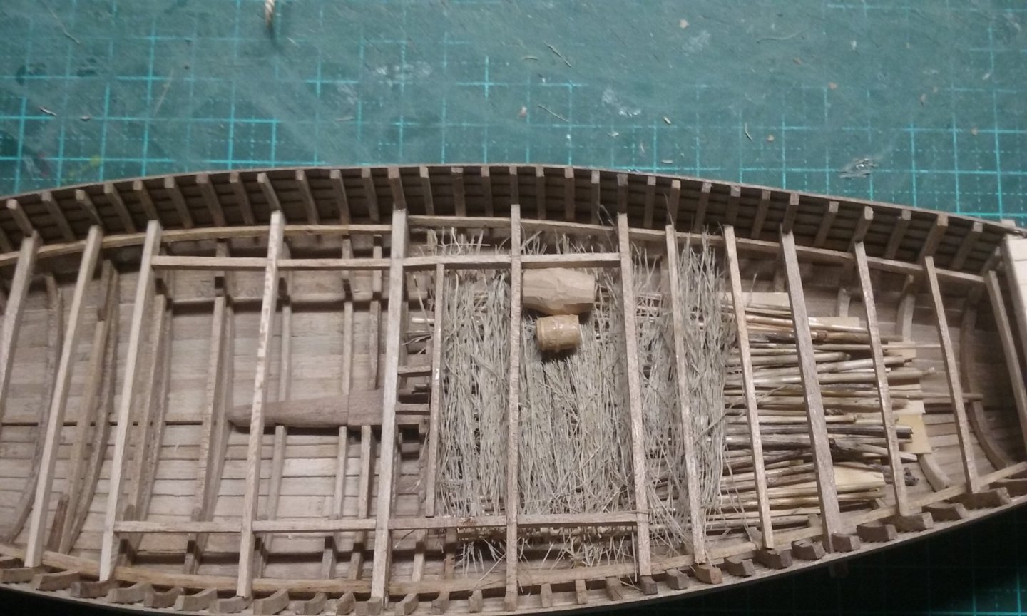
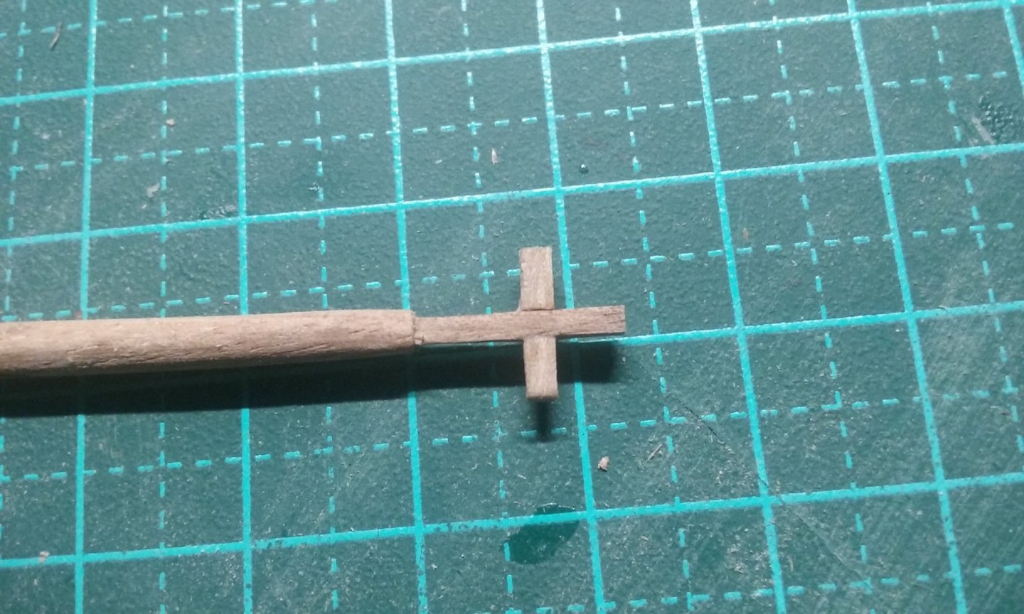
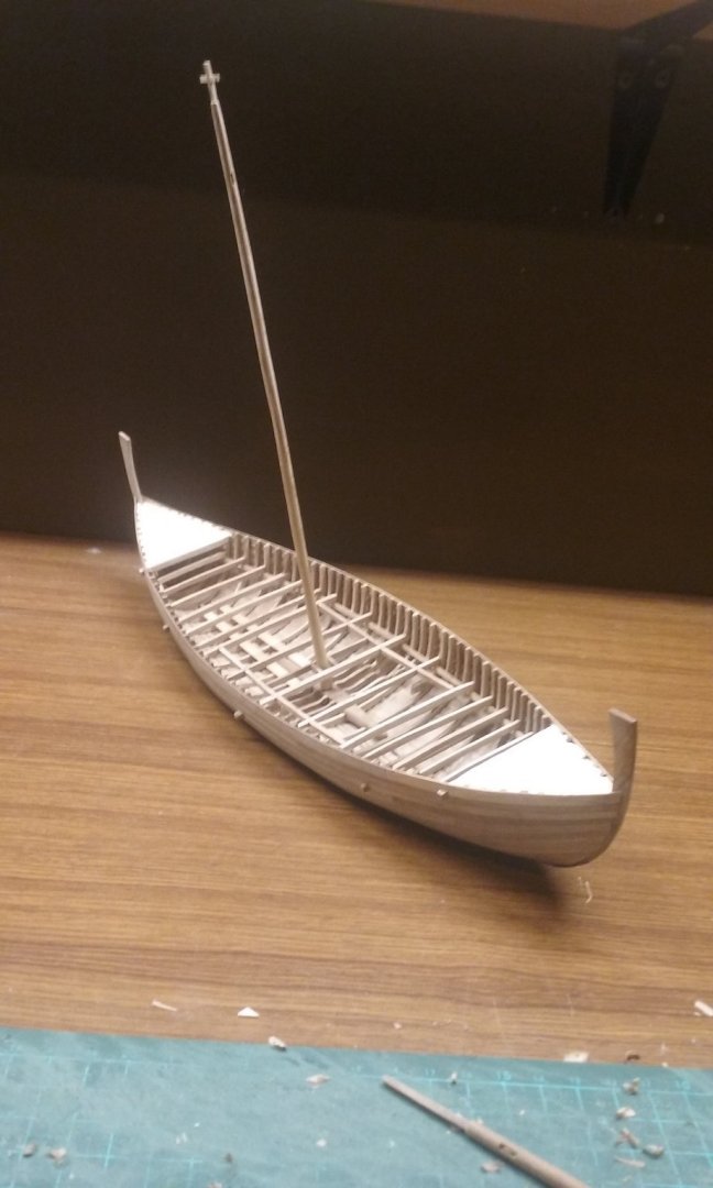
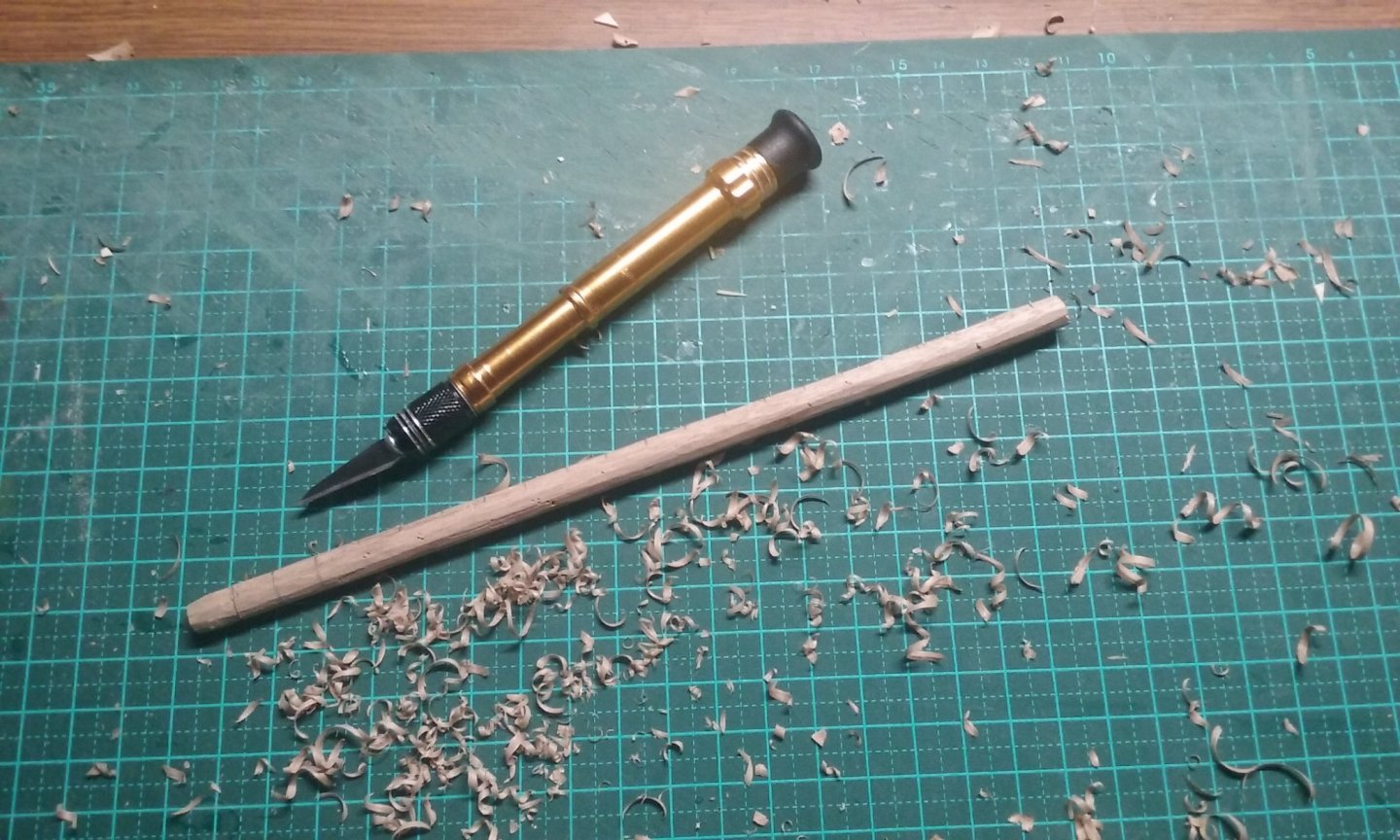
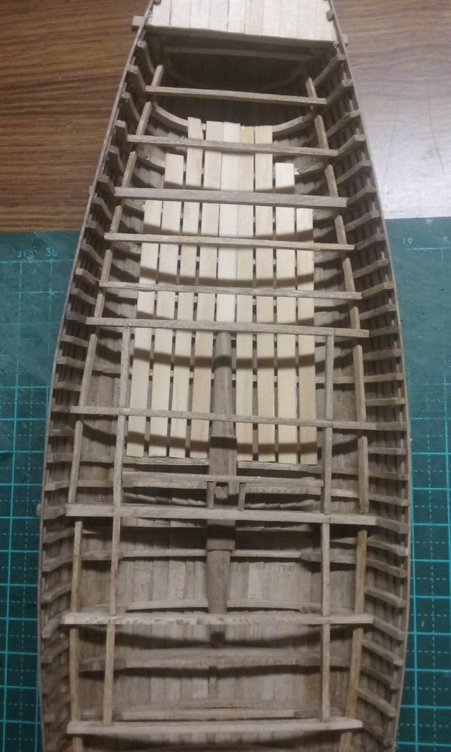
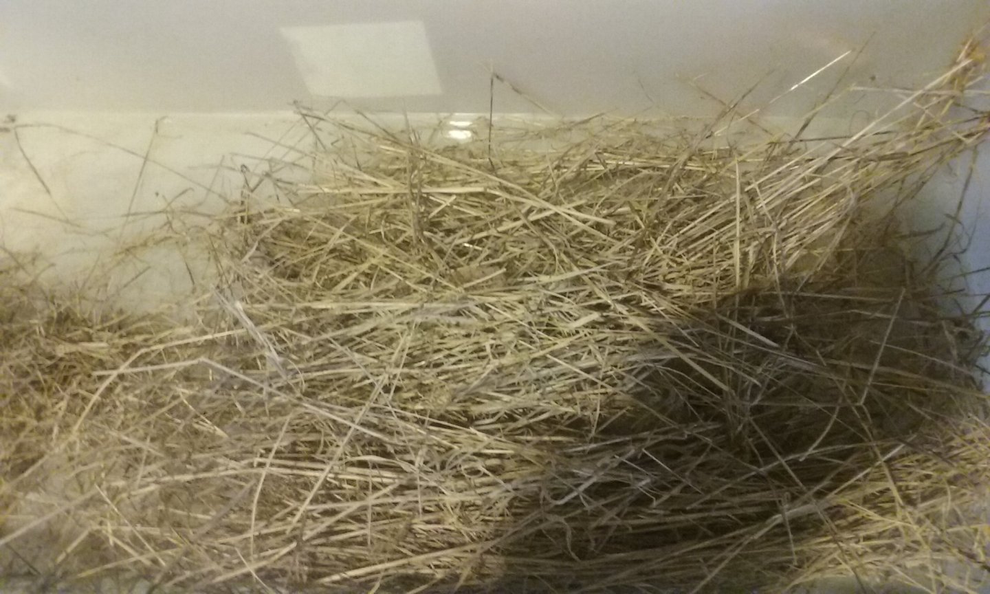
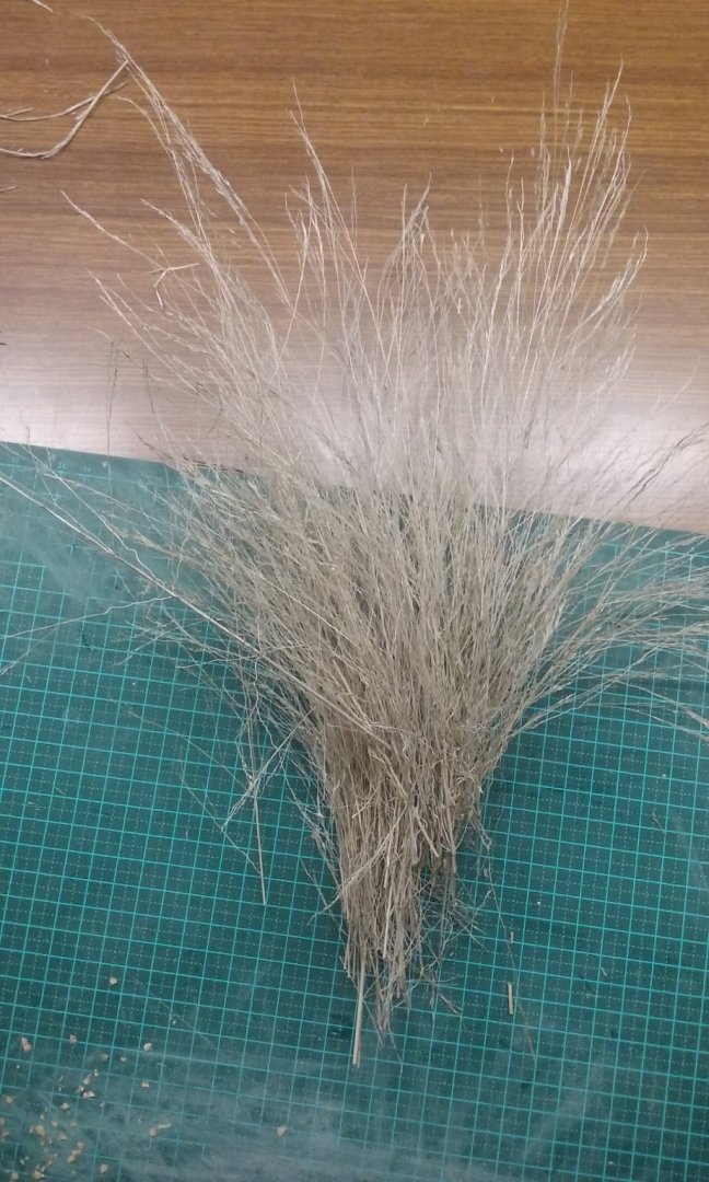
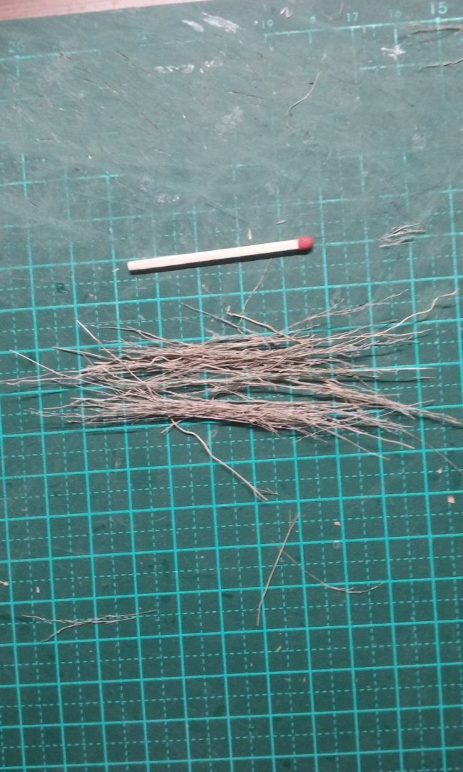
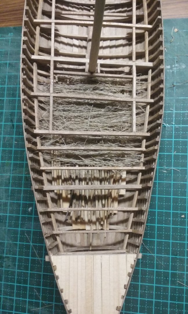
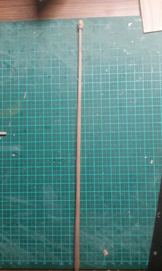
Thanks, Christian. That book sounds very interesting. I've just finished the mast - though the top of the mast of the ship on the Winchelsea town seal is a bit vague, Landström interprets it as having a cross at the top, in line with the seals of other towns such as Melcombe Regis and Hythe, as well as several manuscript illustrations. So here's the cross at the top - a halving joint for the crossbar. Here's the mast dry fitted - the cross seems always to be visible from the side rather than the front as I would have expected, though this might be artistic license to make sure it can be seen in a profile view of the ship. And now based upon the Ijssel cog, the planking for the bottom of the hold And "branches" - actually dry weeds from the street verge opposite the house - laid on top of the planking. and "brushwood" (also weeds) to bed down the barrels that are the ship's cargo. Barrels under way - twenty-one of them. Barrel hoops just begun More to come. Steven


- 327 replies
-
- 18
-
-
I'm all but certain the mast was not recovered from the Bremen cog, or from the Ijsselcog. It seems to be one of the first things to go. It's only in cases like the wonderful ships of the Black Sea that masts survive. And the Bremen cog was apparently under construction when she was washed away by a flood and buried in silt, so she may never have had a mast at all. That being the case, I'm assuming that the mast of the replica as based on speculation and educated guesswork. Which is what I'm doing with my nef anyway, so no worse off, I suppose . Steven
-
I'm not sure there's much difference. As far as I know, though, no cog masts have been found either, so I suppose the question is moot - unless you're aware of some characteristic about cog masts that I don't know about? Steven
-
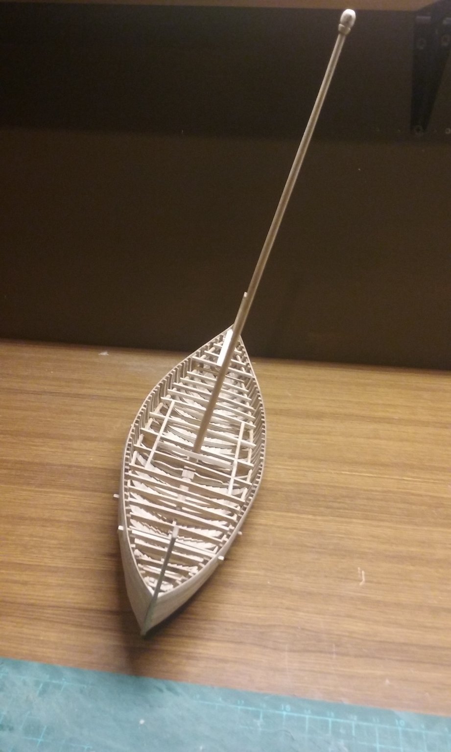
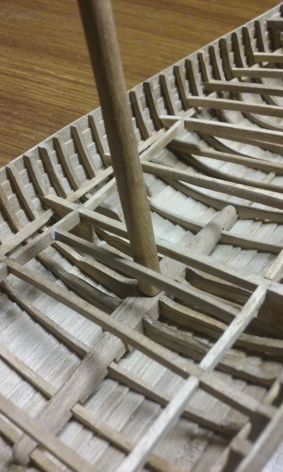
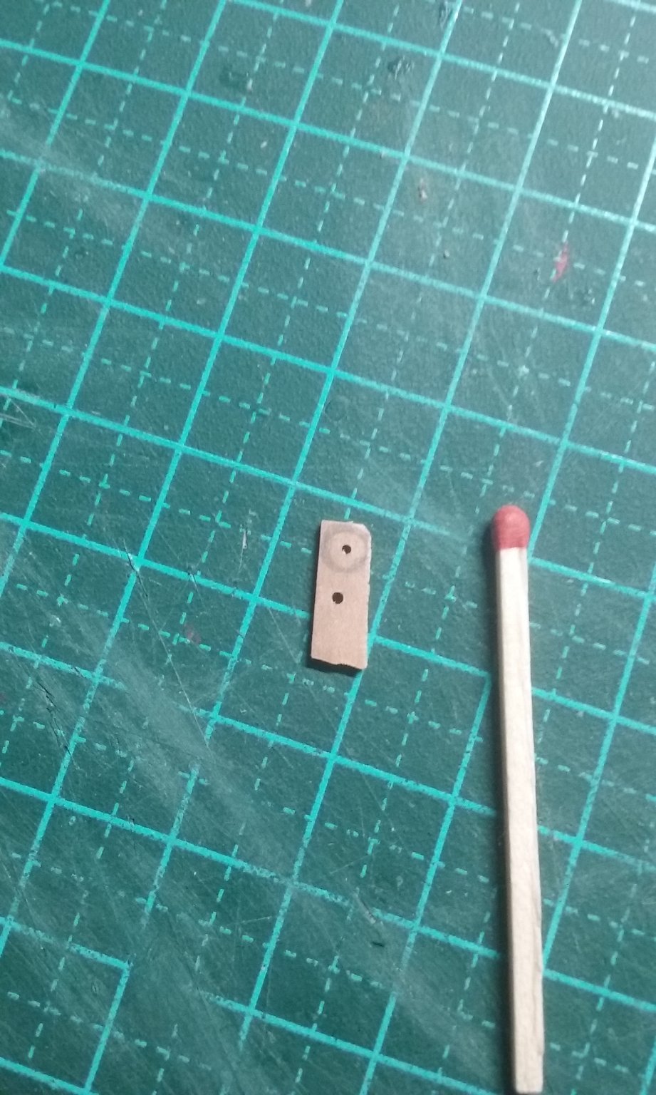
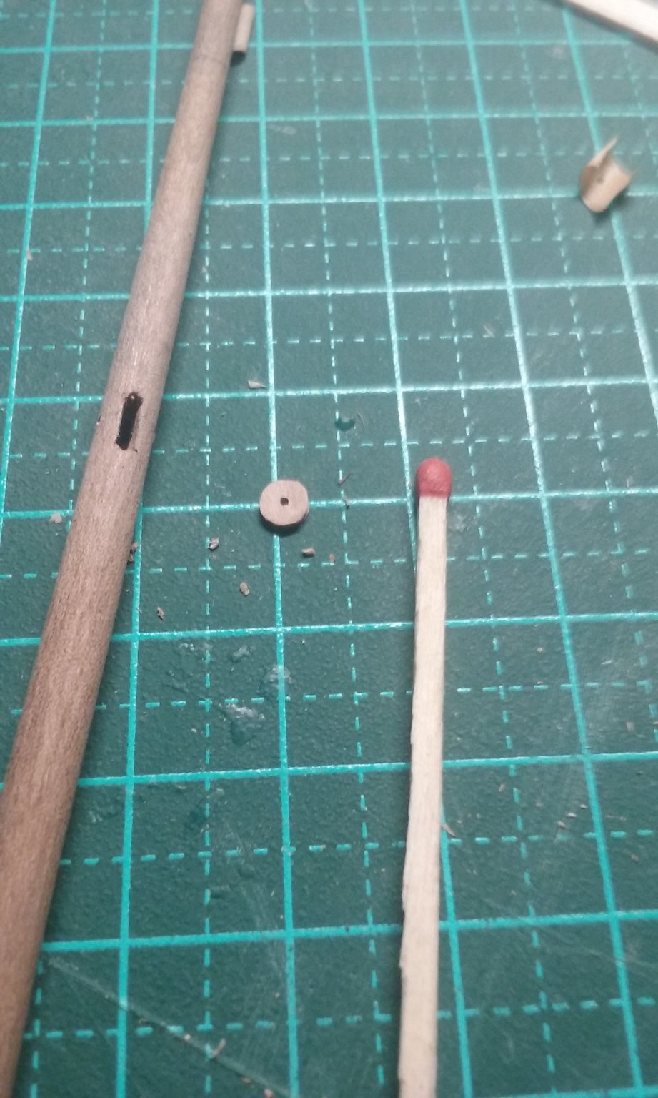
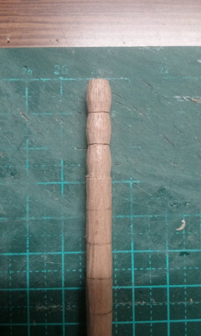
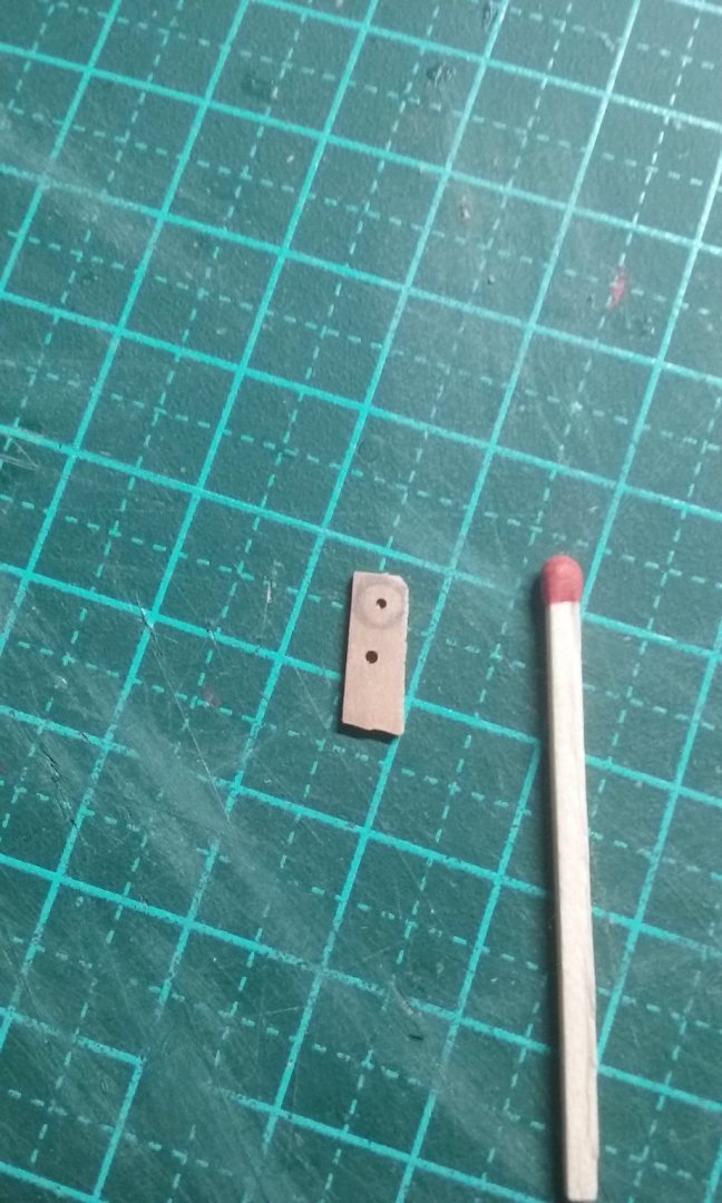
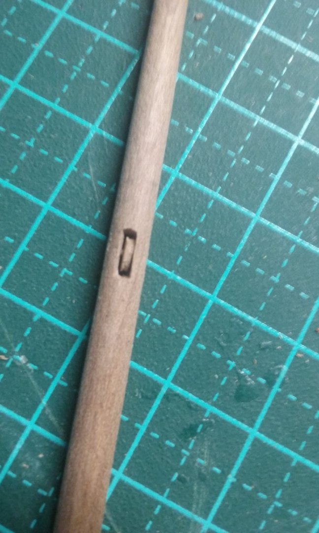
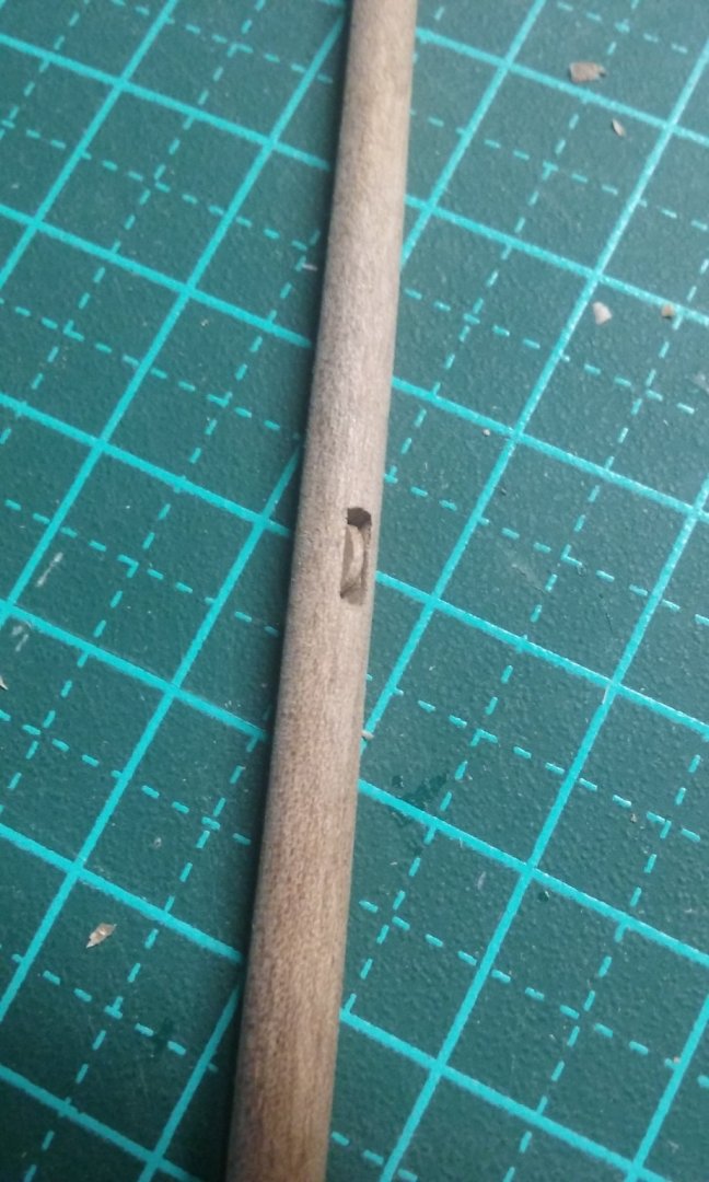
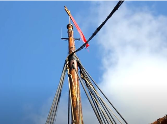
Some more progress. Putting in the mast partners. The mast is recycled from my dromon model and will need to be altered. As nobody's ever found a mediaeval European mast , I really wasn't sure how the halyard worked, but I did find a photo of a Viking ship replica that used a sheave in the mast, so here I am making a sheave for the halyard. Here's the mast before . . . Here's the mast after. More to be done to make it right for the nef. Planking of the foredeck. Steven


- 327 replies
-
- 16
-
-
Very interesting conclusions, Dick. Worth making the model just for that, perhaps. I like the idea of the Nydam ship. Looking forward to it. Steven
- 186 replies
-
- 2
-
-
- keelless
- reverse clinker
- (and 4 more)
-
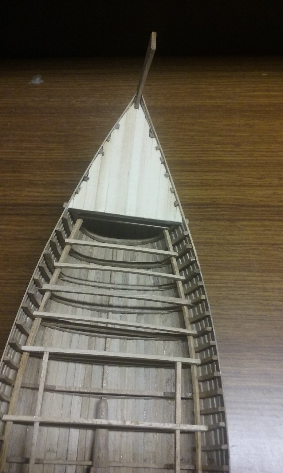
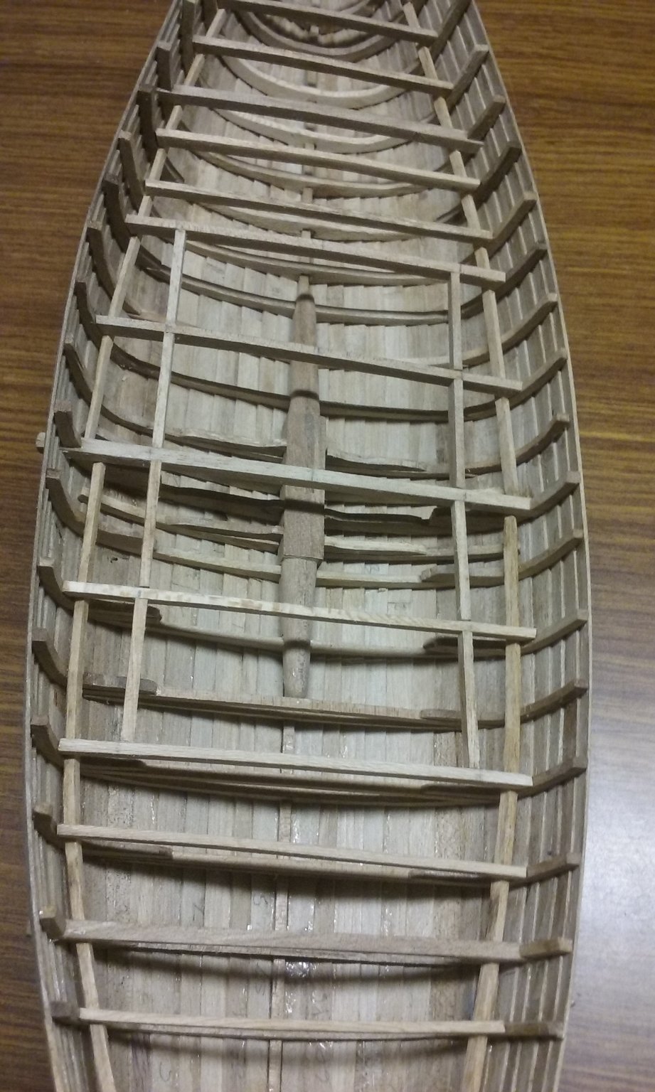
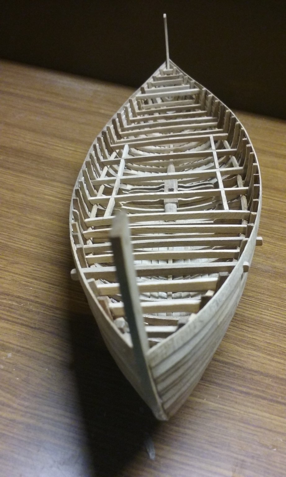
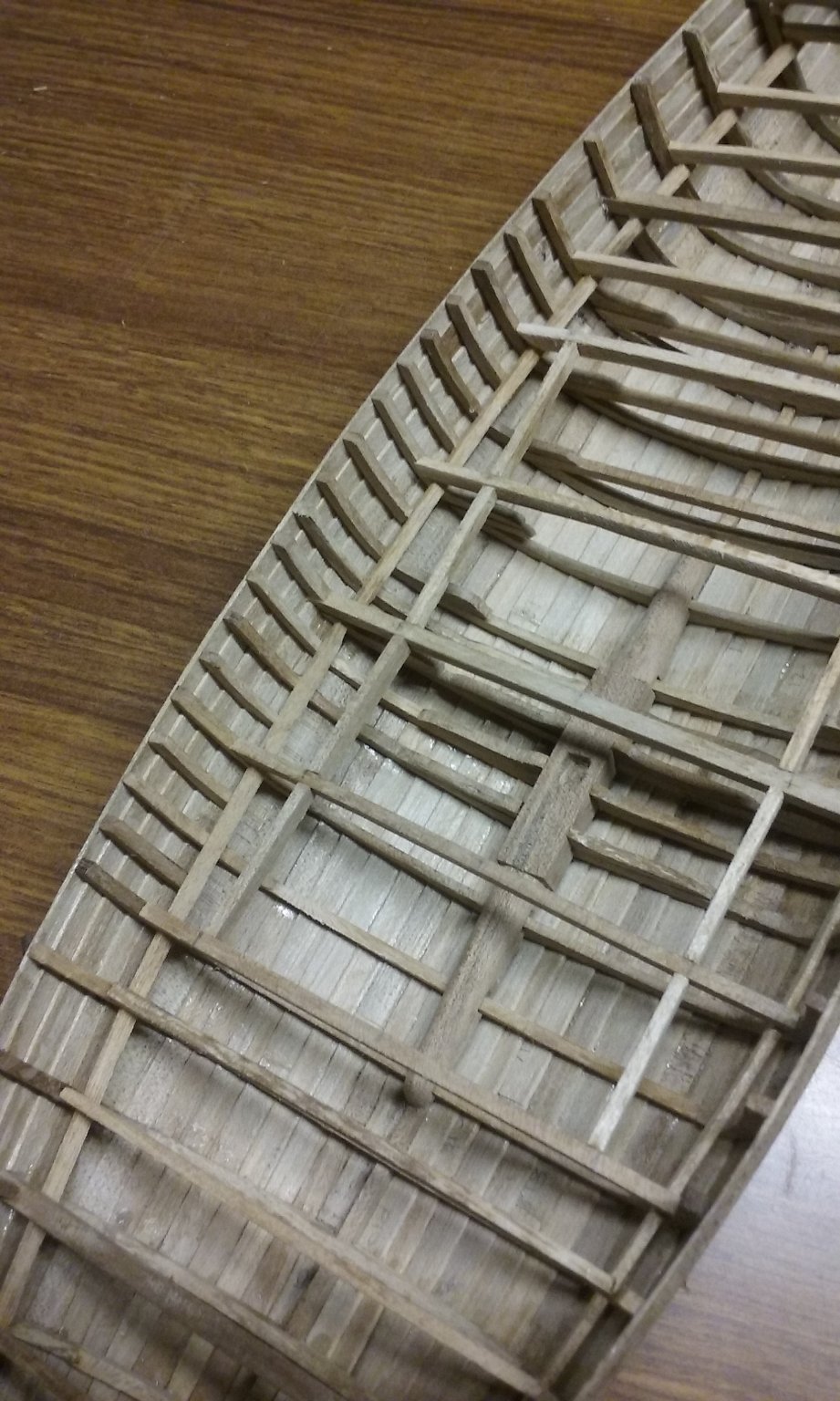
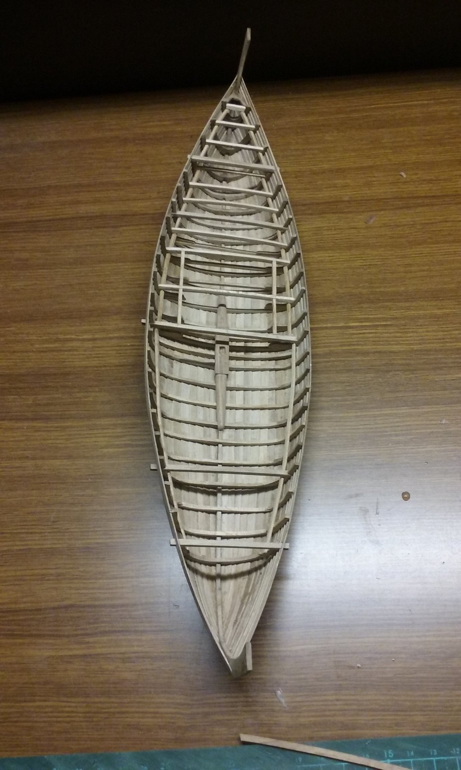
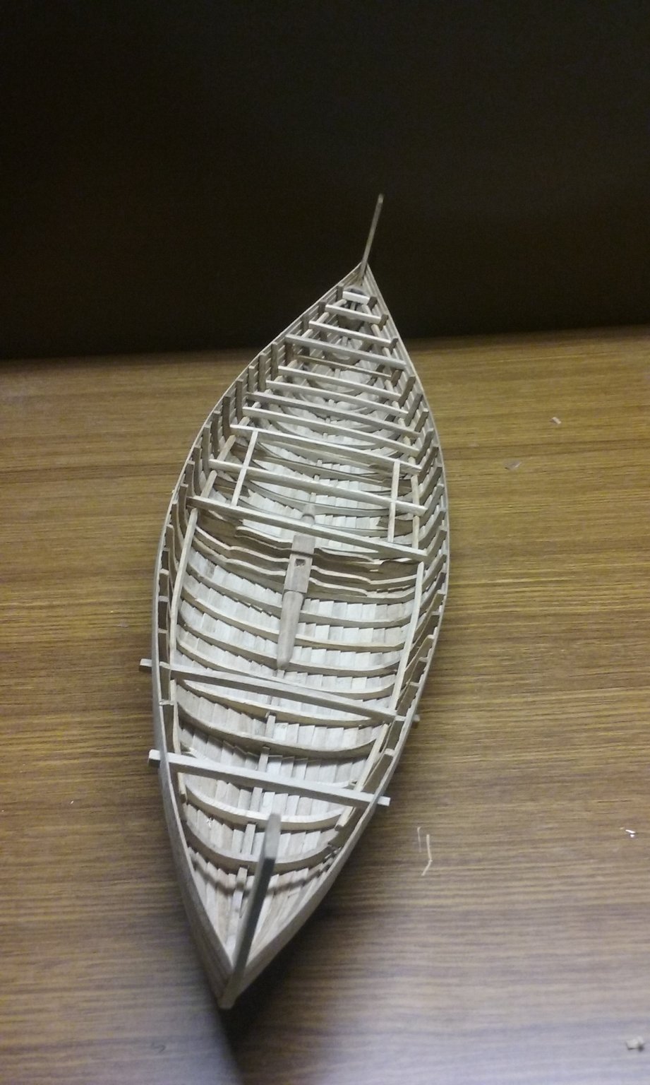
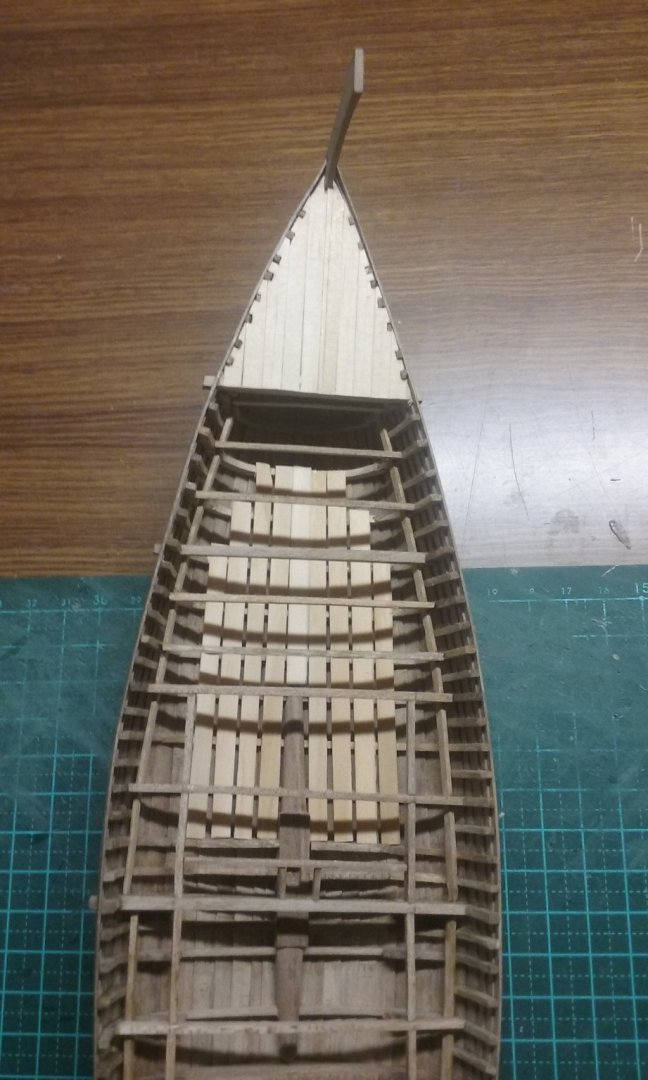
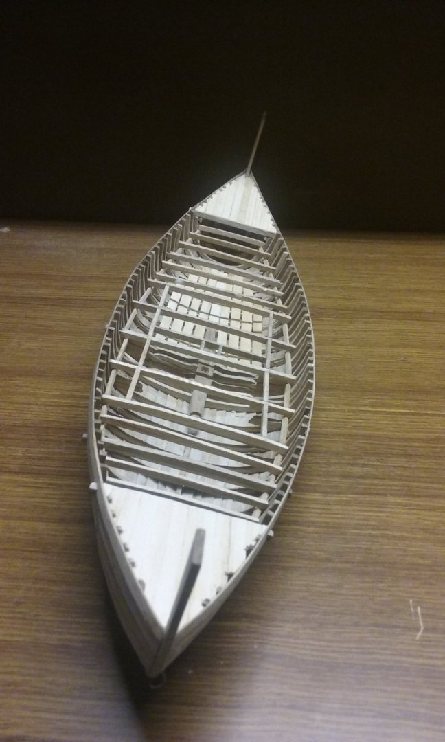
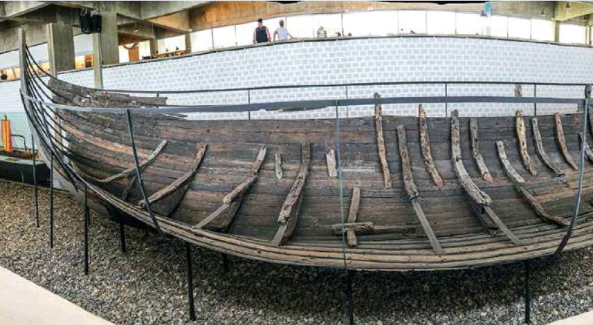
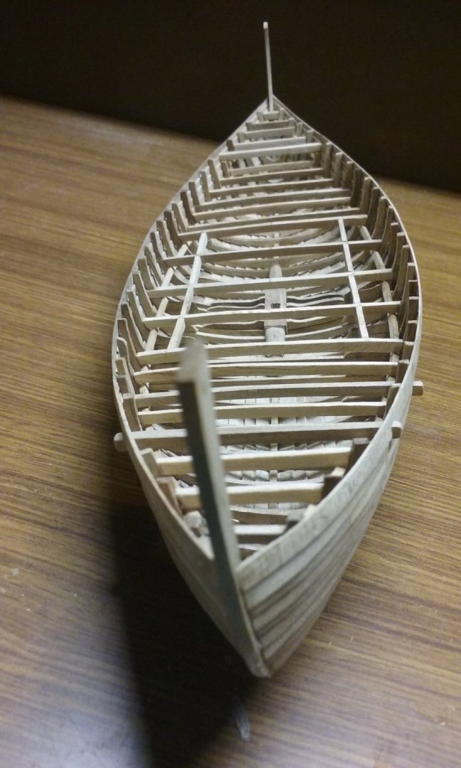
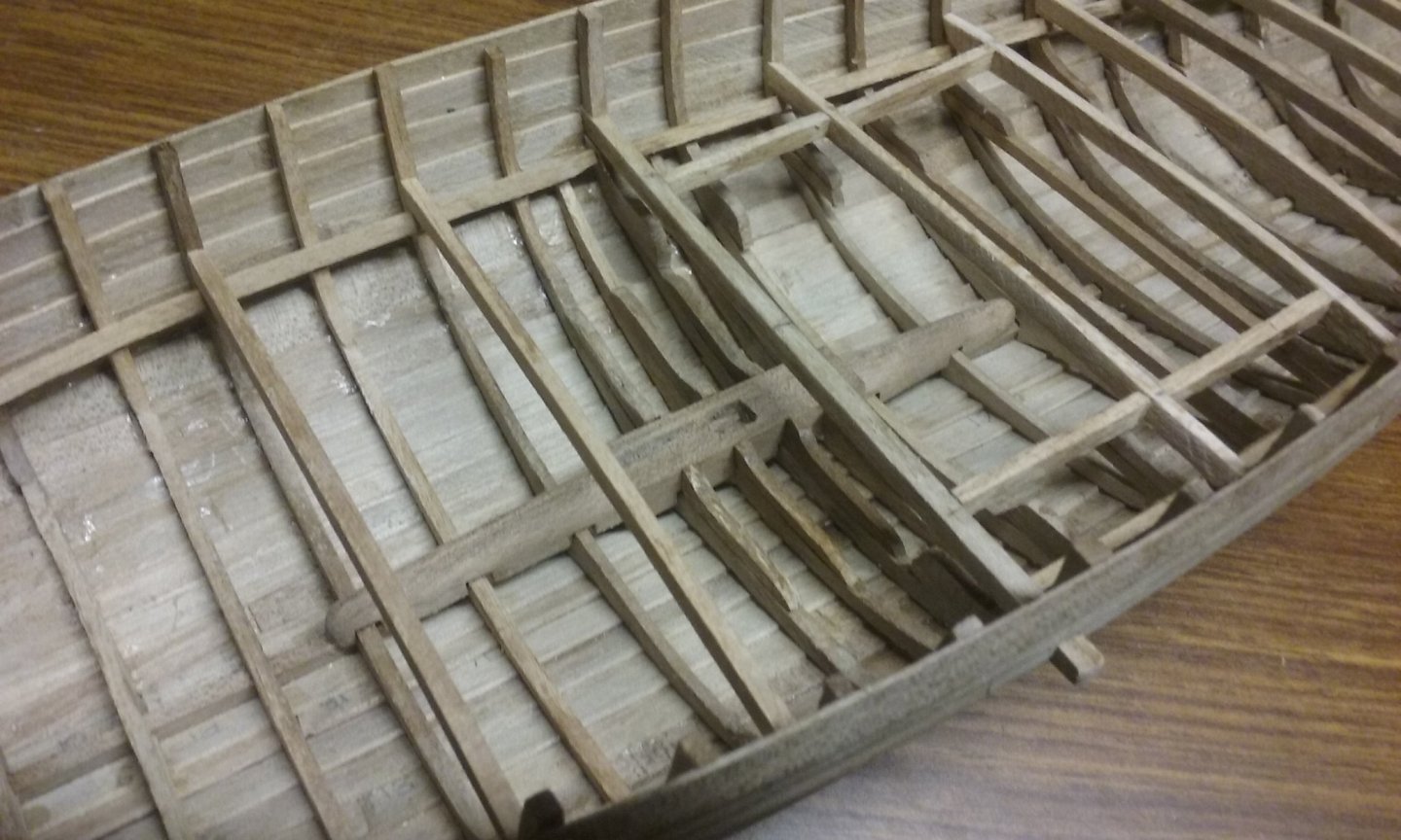
Thanks for all the likes. Christian, I'm basing the spacing of the frames on the Skuldelev 1 knorr, which was also clinker built. (Otherwise I could have saved myself a lot of work and trouble - I only decided to add the extra frames after I saw the photo below). It seems to me that every second frame only goes down as far as the turn of the bilge. I don't know if I will be doing this. Steven
- 327 replies
-
- 10
-
-
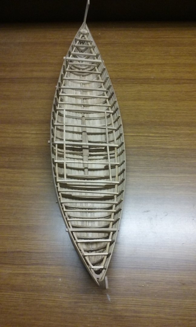
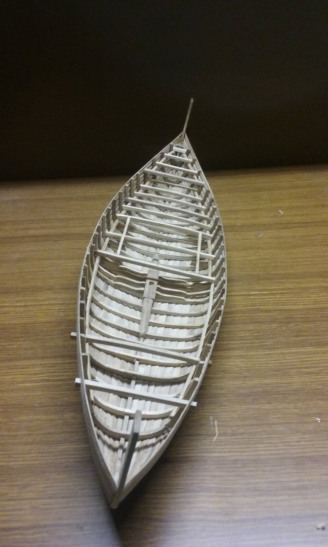
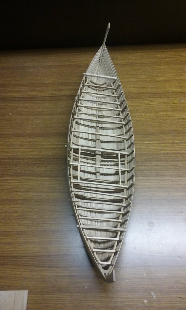
Thanks for the reply, Tony. I can fully understand the time constraints. I only really got serious progress on my modelling once I'd retired. Pearl luggers are fascinating vessels (though strictly the West Australian ones should be called schooners or ketches, as they were gaff rigged). Unless it's been removed, there's an old lugger at the Maritime Museum in Fremantle. I'm looking forward to seeing what you decide to build once you get the time. In the meantime, here's the latest progress on the nef. Deck beams for the after deck. Side beams for the hold opening Adding intermediate frames between the existing ones. Firstly the bits that show above deck level. I will probably add intermediate floor timbers as well, at least in the hold, as I intend to have the hold partly exposed (a couple of removable deck planks removed) to show some cargo. Not sure if I'll carry the intermediate floor timbers all the way through the hull, as most of them will be hidden by the decks. Steven


- 327 replies
-
- 16
-
-
A very nice bit of experimental reconstruction, Dick. I'm still not sure whether I believe the hulc really was like this, but I think it was worth it to find out how practical it might have been, and you've certainly done that. Oh, and made a very attractive model, to boot. Steven

- 186 replies
-
- 2
-

-
- keelless
- reverse clinker
- (and 4 more)
-
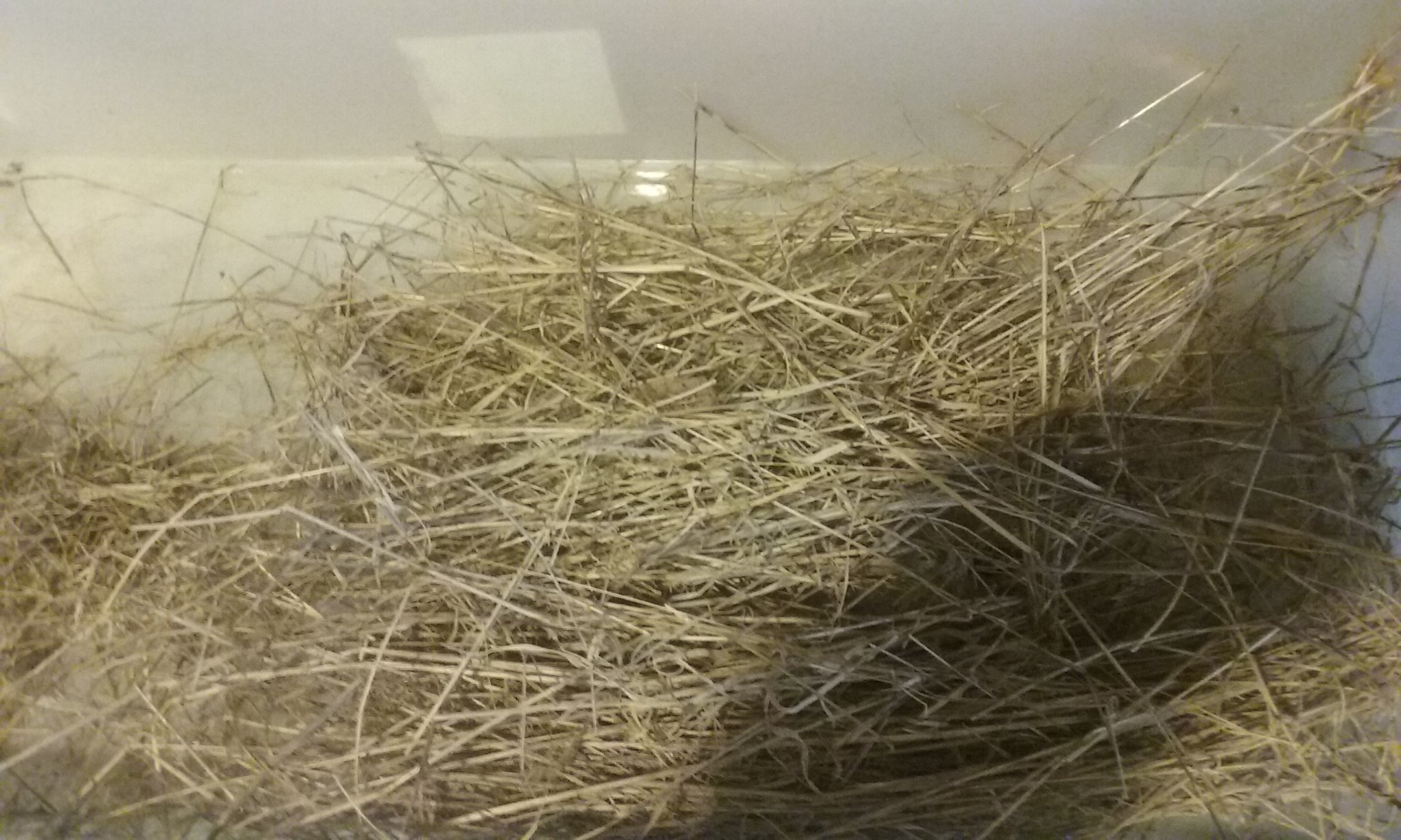
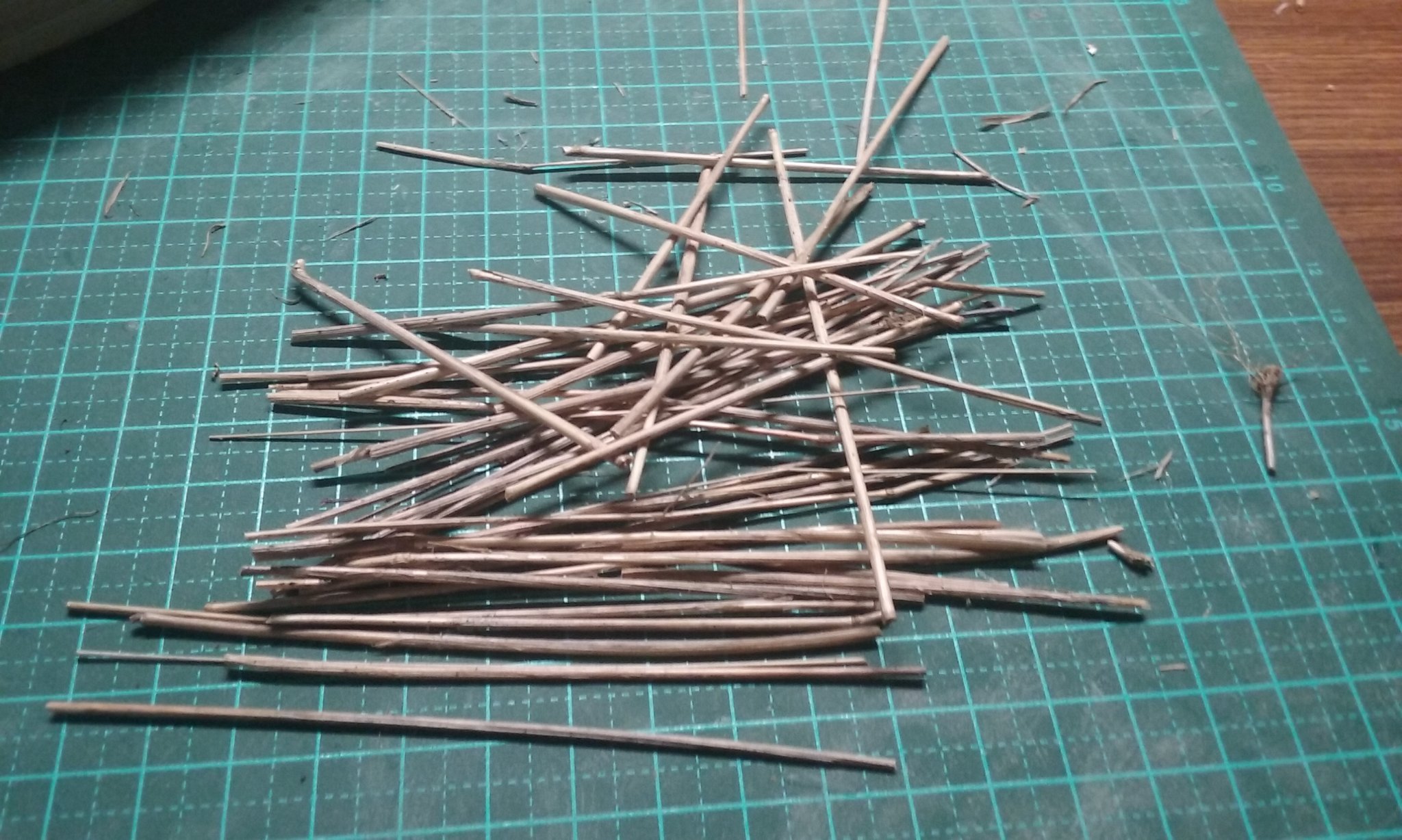
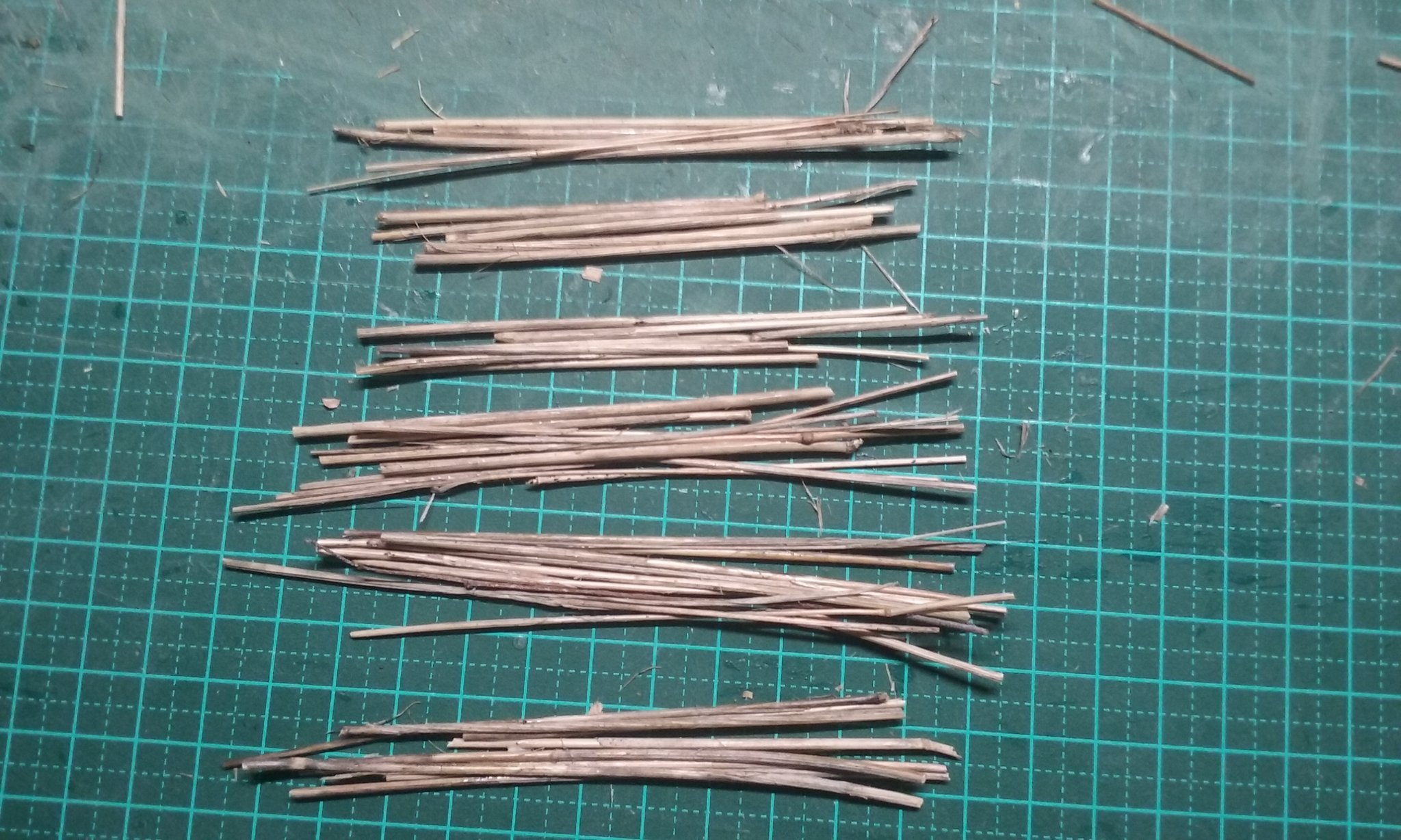
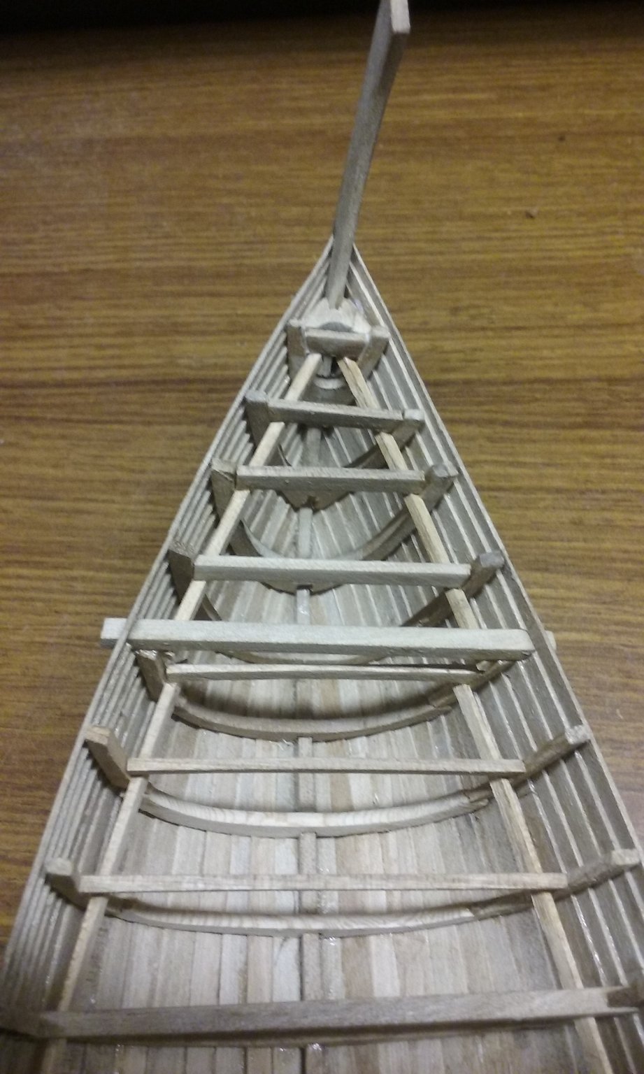
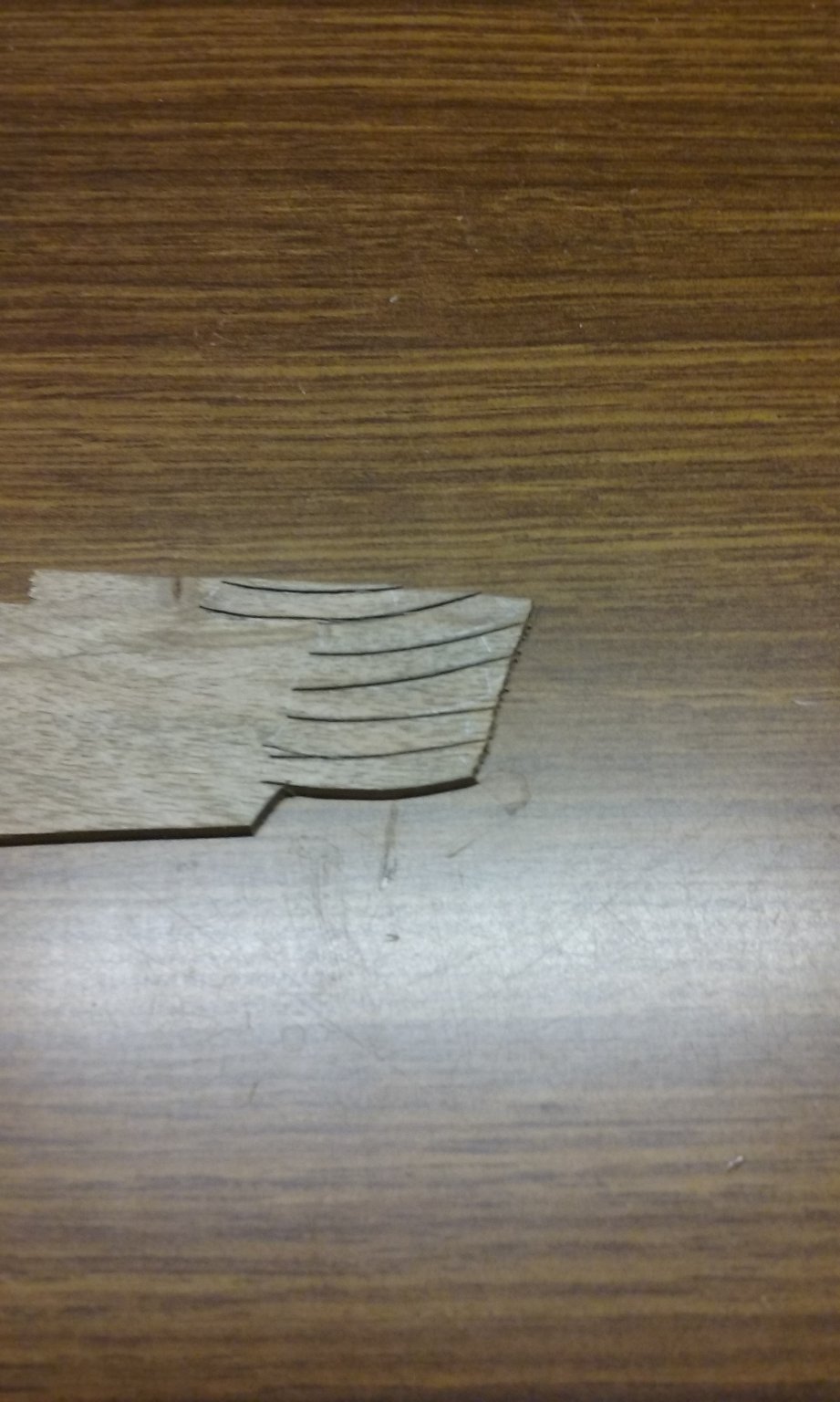
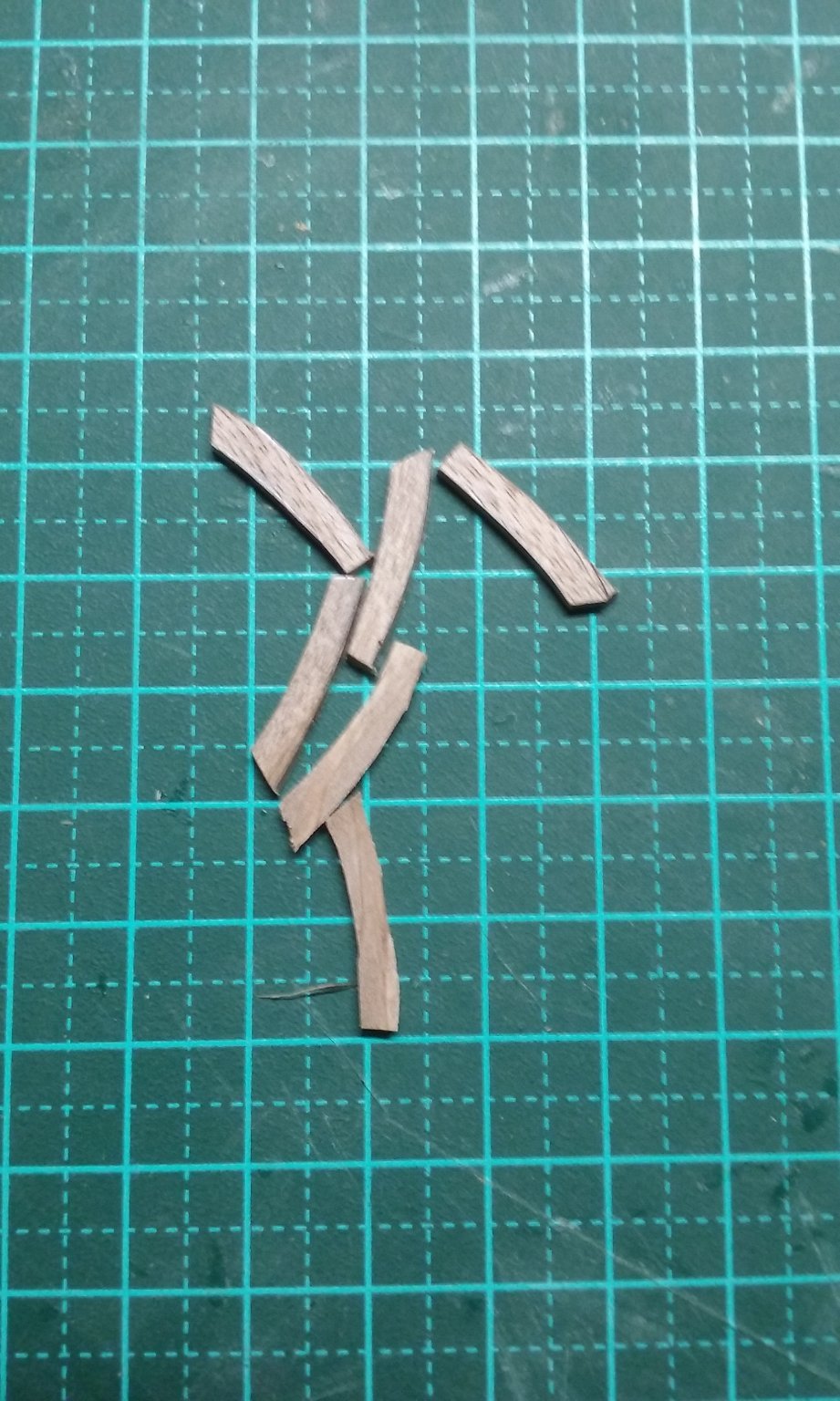
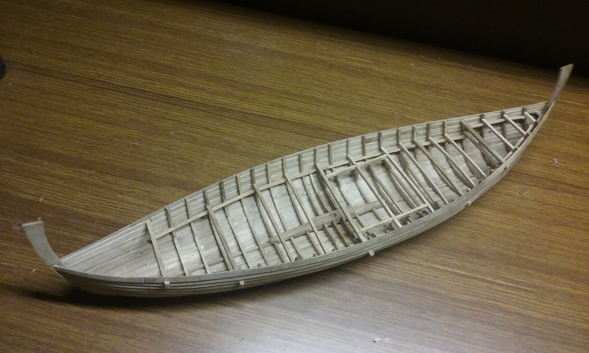
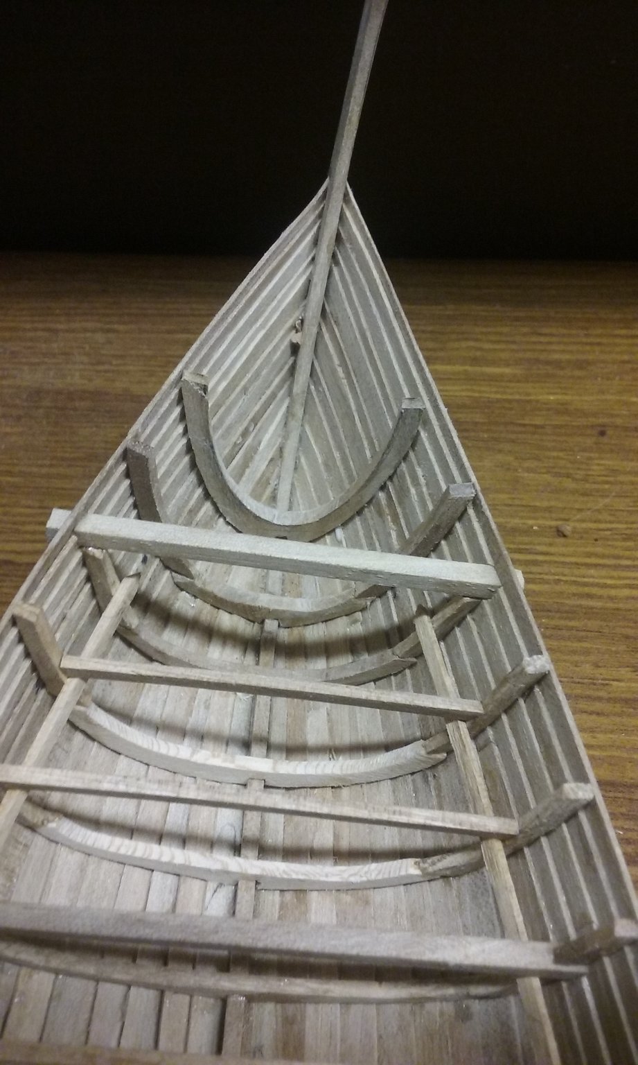
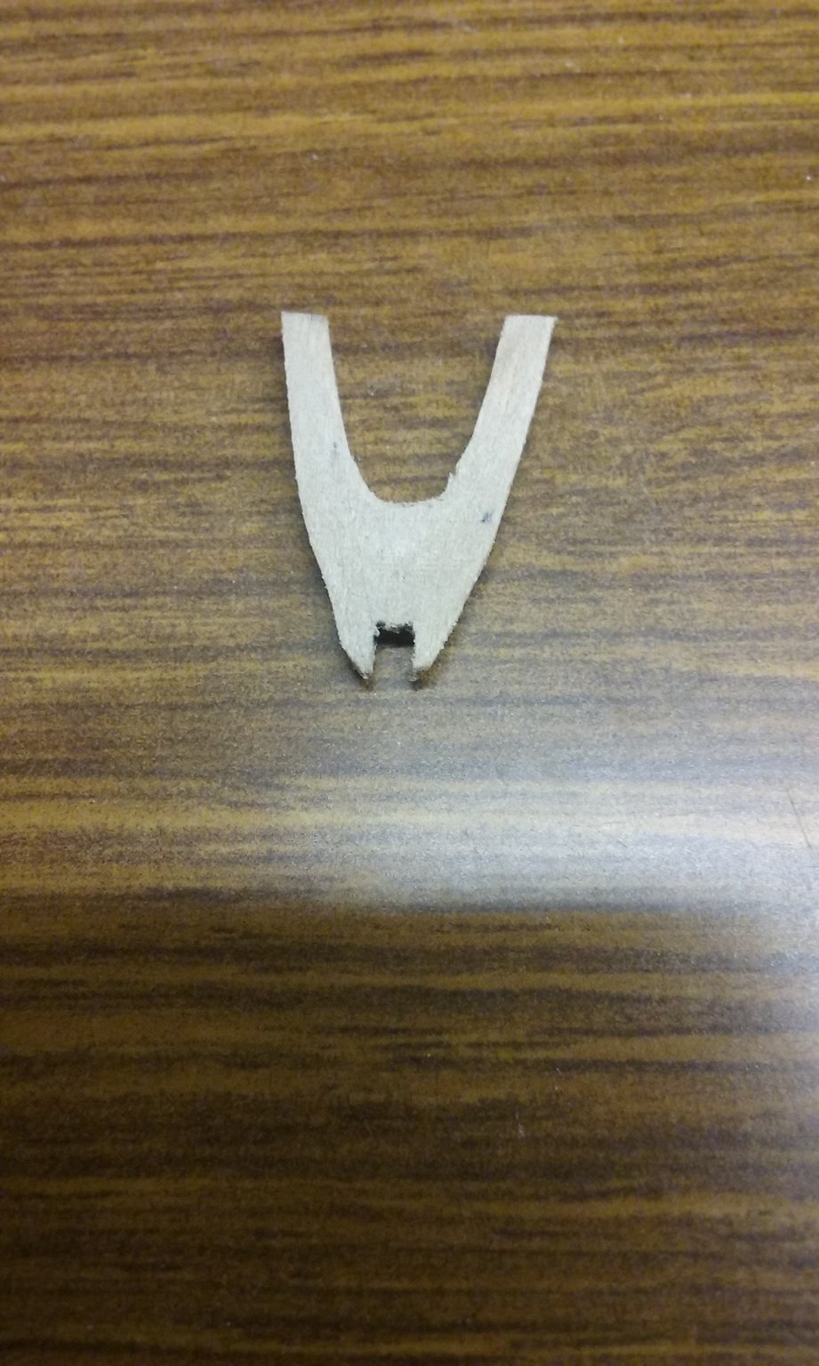
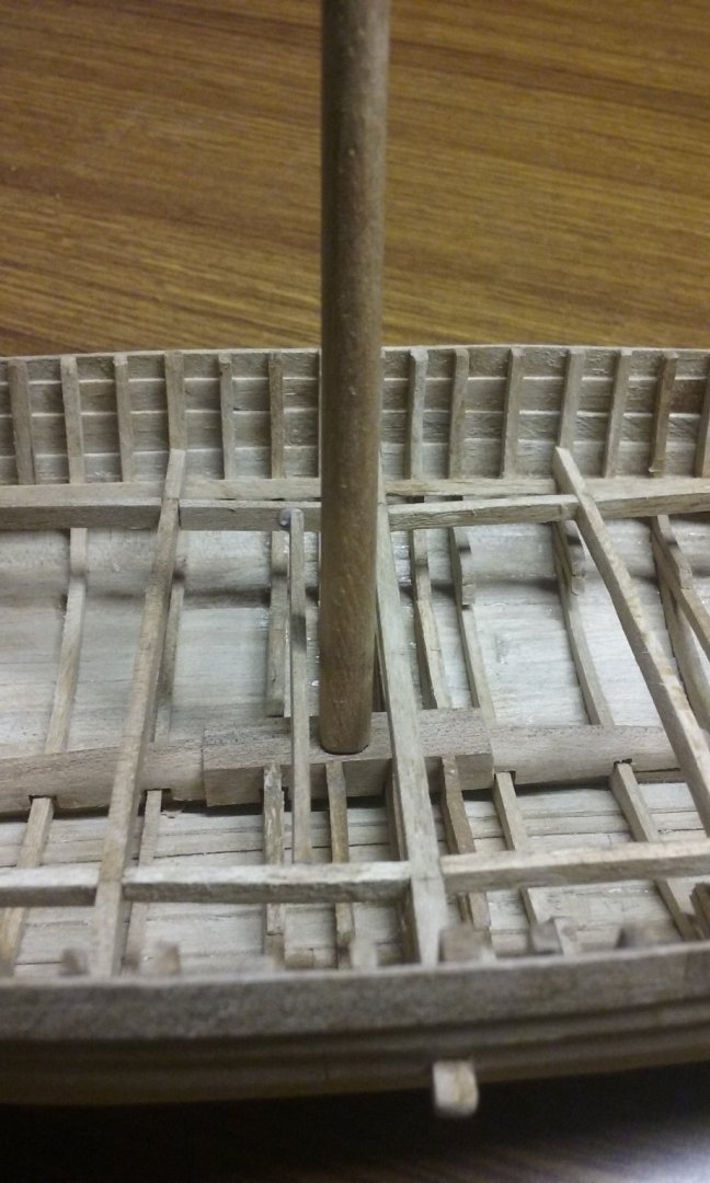
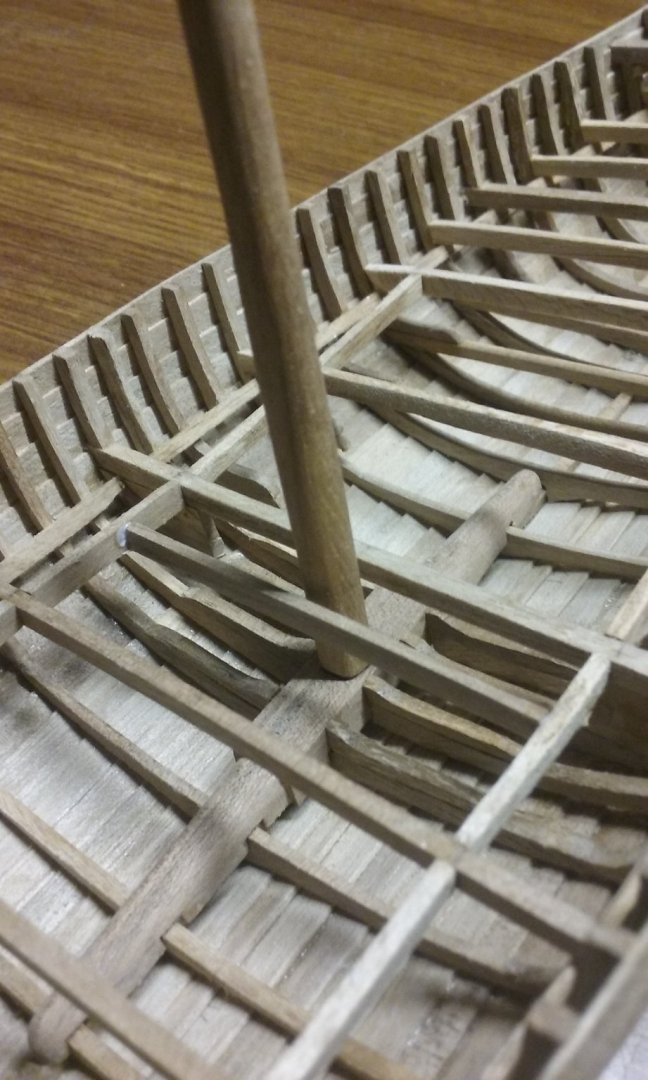
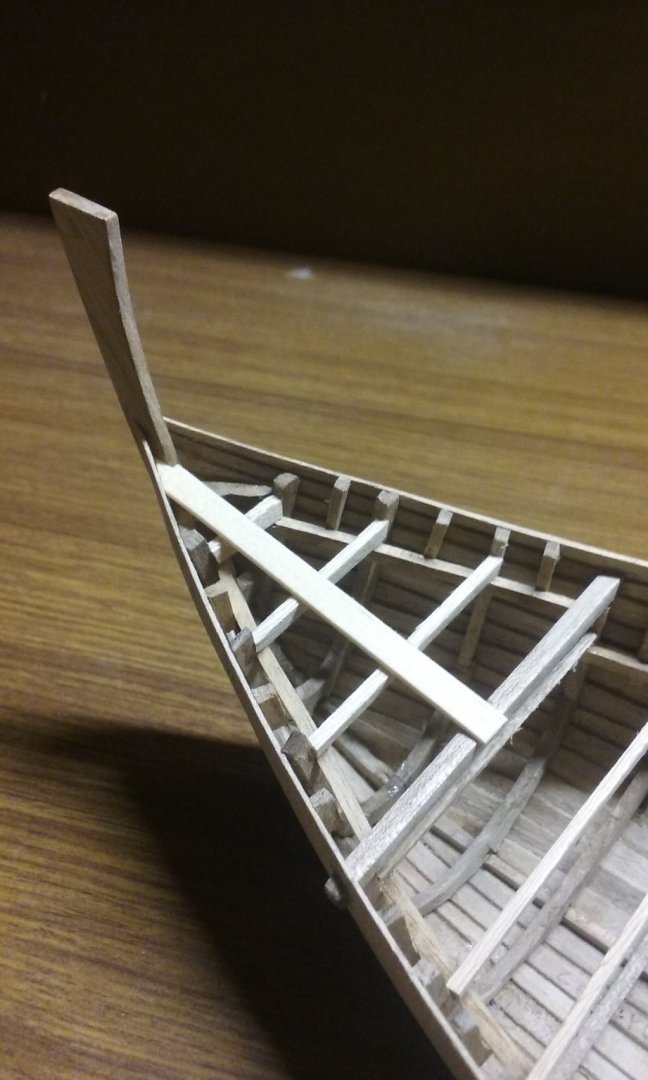
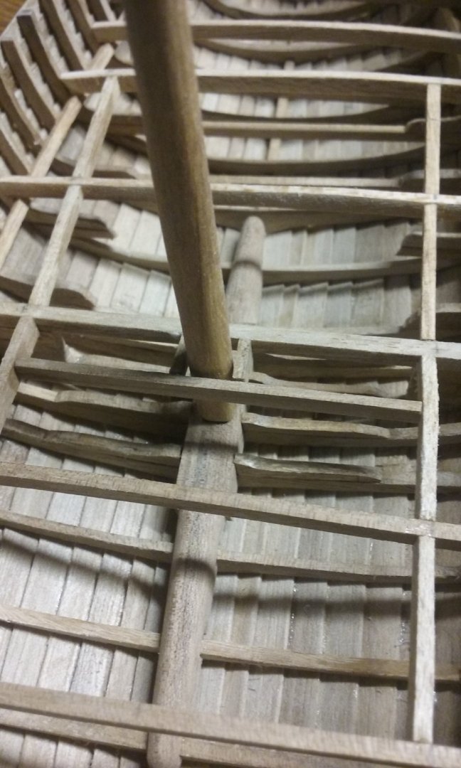
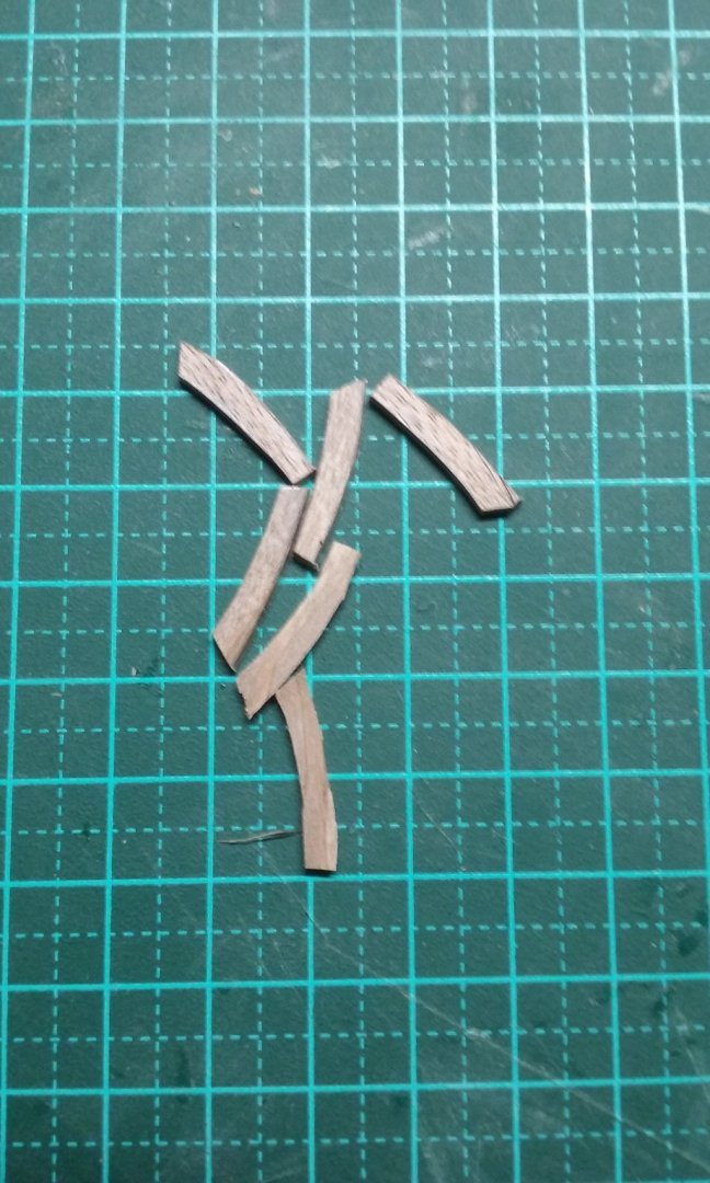
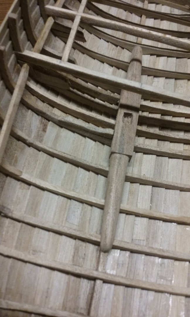
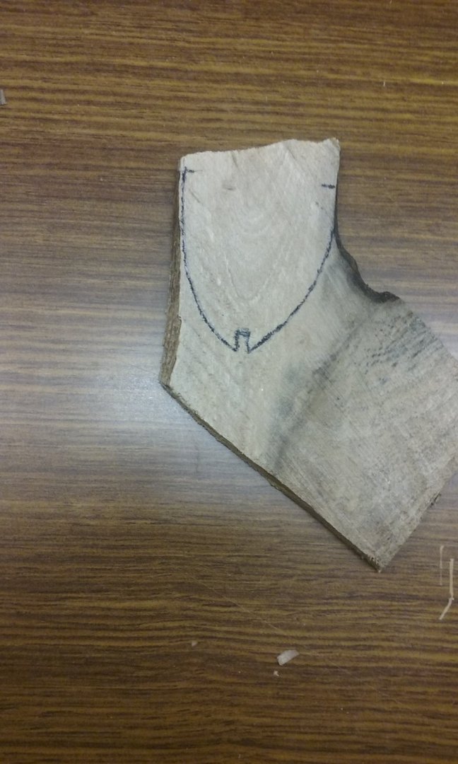
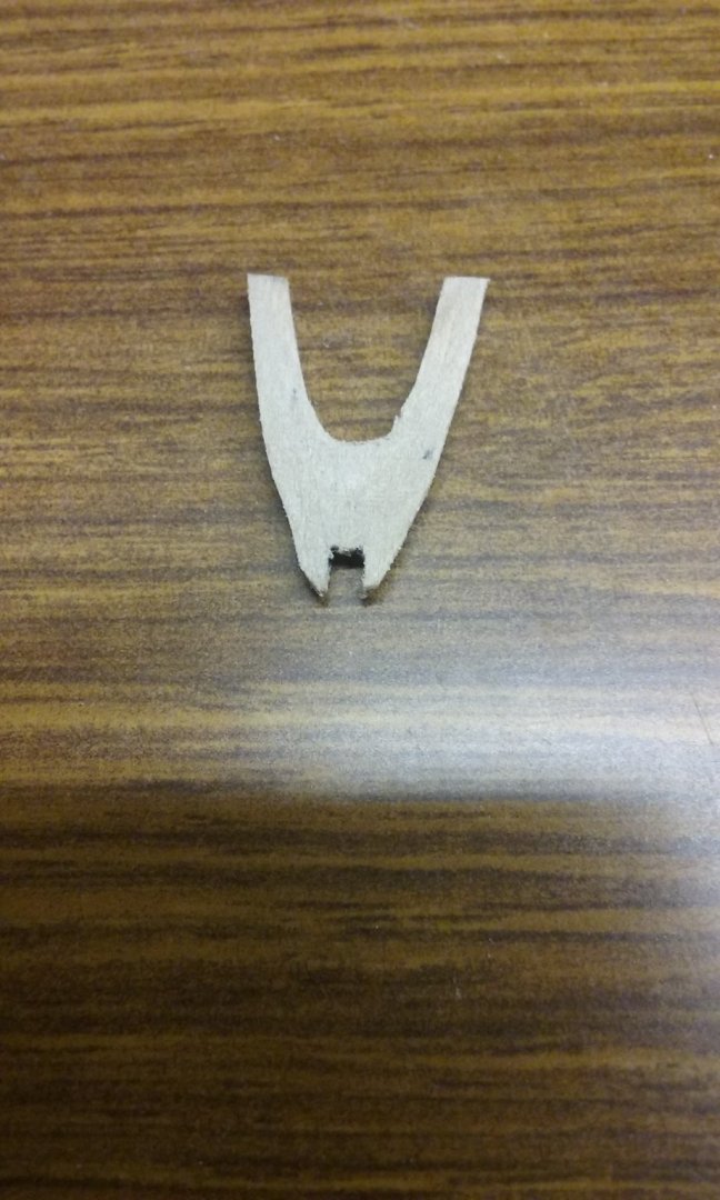
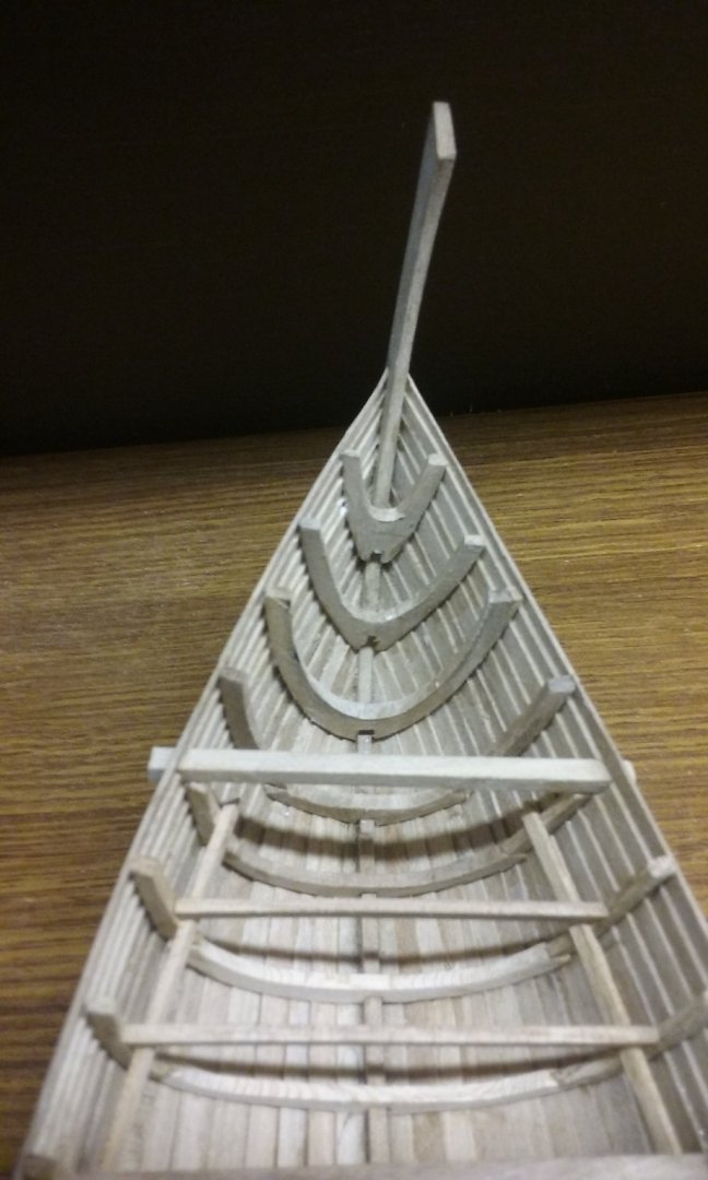
Thanks, Tony and Pat. And thanks everybody for the likes. Pat, I wouldn't be too worried about the speed with quality like yours. And the time you take to do the research to get it right. Amazing that such a (relatively) recent ship as Victoria, built in the days of photography and printed manuals should be so hard to get correct information on. But she was a bit of a trailblazer, and not enough people were taking photos or writing stuff down. Tony, I've seen your very informed comments on other people's builds, but haven't seen your own log. Am I missing something? Anyhow, I do seem to be on a bit of a roll, which is nice. Earlier, particularly during the planking, it seemed as if I wasn't getting anywhere fast. So this makes a nice change. I've added intermediate frames in line with the mast step, to make a pozzie for the knees. Eventually there will be intermediate frames between every pair of frames you see here. And here are all the knees in position. The only problem is that I was planning to have some of the removable planks above the hold removed, so some of the cargo would be visible, but the mast step assembly is so pretty I really don't want to cover it up as in the Ijsselcog's archaeological report (referenced above) "In the area around the mast step the remains of a removable or false ceiling was found. It consisted of longitudinal timbers, placed on the first and second ceiling strakes and covered with loose planks and dunnage (Fig. 16). Salix twigs, branches, and straw were abundant across the whole width of the false ceiling. This construction would have kept the cargo dry by separating it from accumulating bilge-water and, at the same time, covering the open space between the floortimbers. The false ceiling and the remains of what were probably shifting-boards in the rear of the ship are indicators for the internal layout of cargo space. It is plausible that the cog was able to carry a load of casks amidships for which a dry, horizontal, upper cargo deck was reserved. The shifting-boards in the rear could have contained sacks of merchandise, such as grain." and the reconstruction drawing in my post #173. I'll have to think about it a bit and decide which way I want to go. [Edit - But looking again at that drawing, are they perhaps showing that the layer of planking, branches etc isn't over the mast step assembly - at least not over the knees I took so much trouble about? Hard to be sure, but it would help a lot if that were so.[/Edit] Starting on the frames for the pointy bit at the stern. And here's where the wood with the forked grain from an earlier post comes in handy. Now I need to make and put in the breast hook and the beam clamps and deck beams for the after deck. Coming along . . . To be honest it's been very hard resisting the temptation to make the castles, but I found out the hard way with my dromon that it's a bad idea to make something before you know the space it has to fit in and the other things it has to fit around. All in good time. Steven


- 327 replies
-
- 15
-
-
-
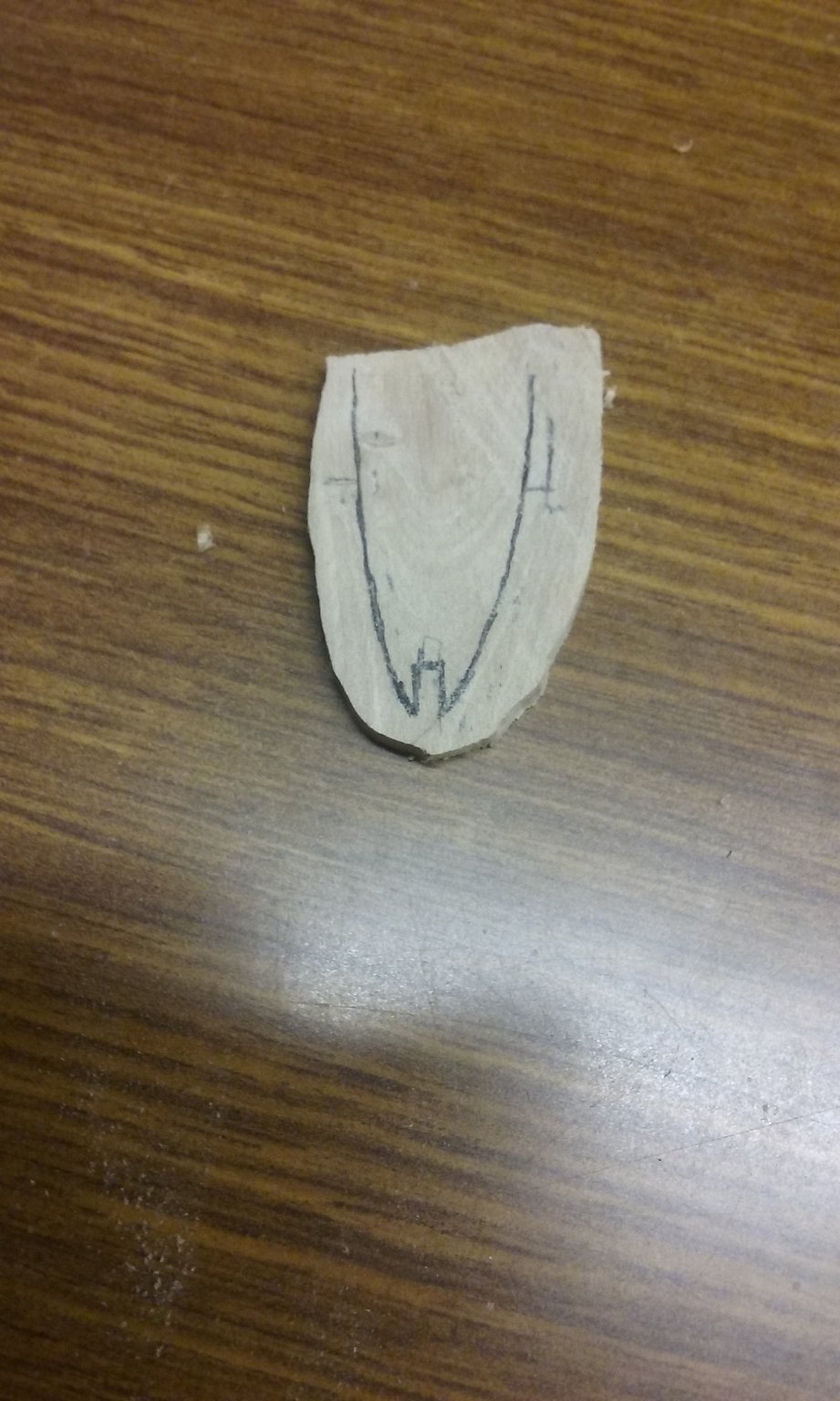
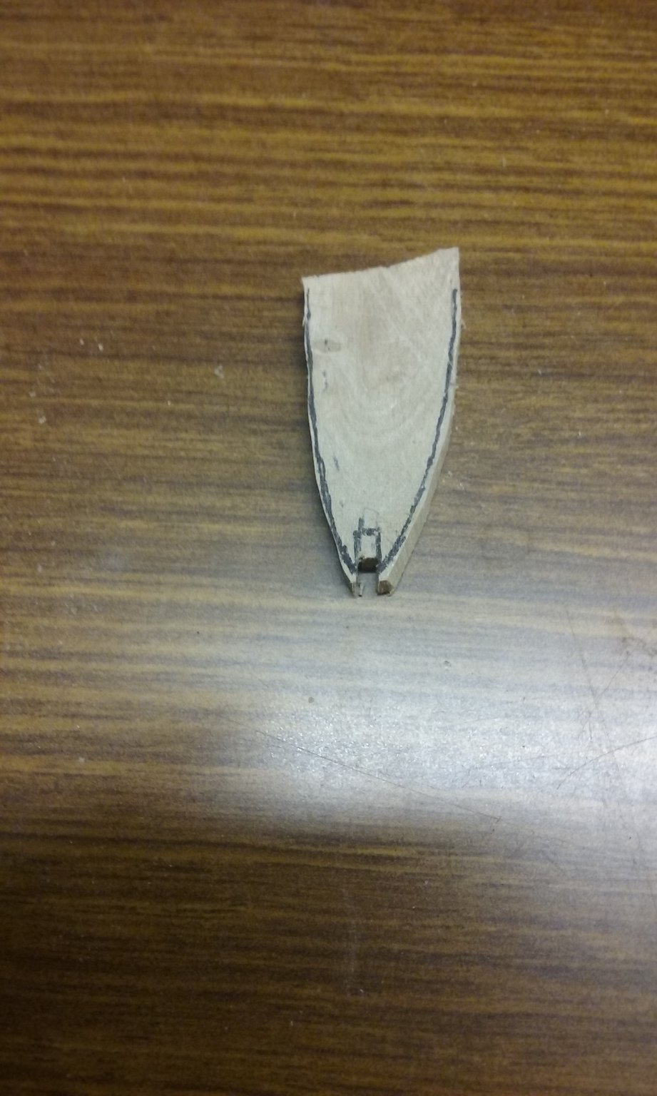
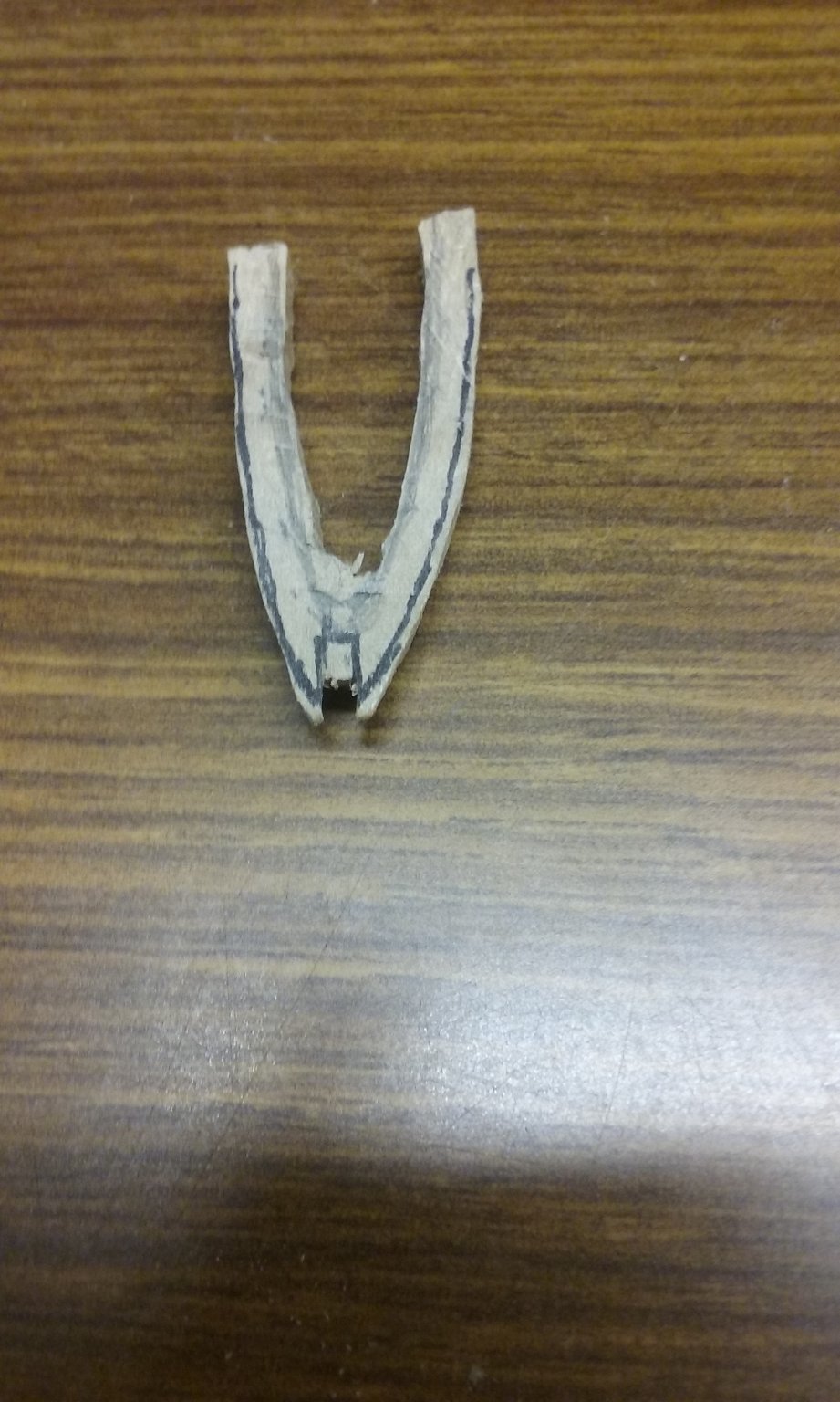
But take more care than I did to make sure the two sides of the plug are exactly the same. Though the differences are slight on mine, when I got to making the frames the lack of symmetry became rather obvious - at least to me - particularly towards the ends. Steven