


Louie da fly
-
Posts
7,990 -
Joined
-
Last visited
Content Type
Profiles
Forums
Gallery
Events
Everything posted by Louie da fly
-
 You're making good progress on this. It's looking great. Steven
- 62 replies
-
- 2
-

-
- amati
- greek bireme
- (and 1 more)
-
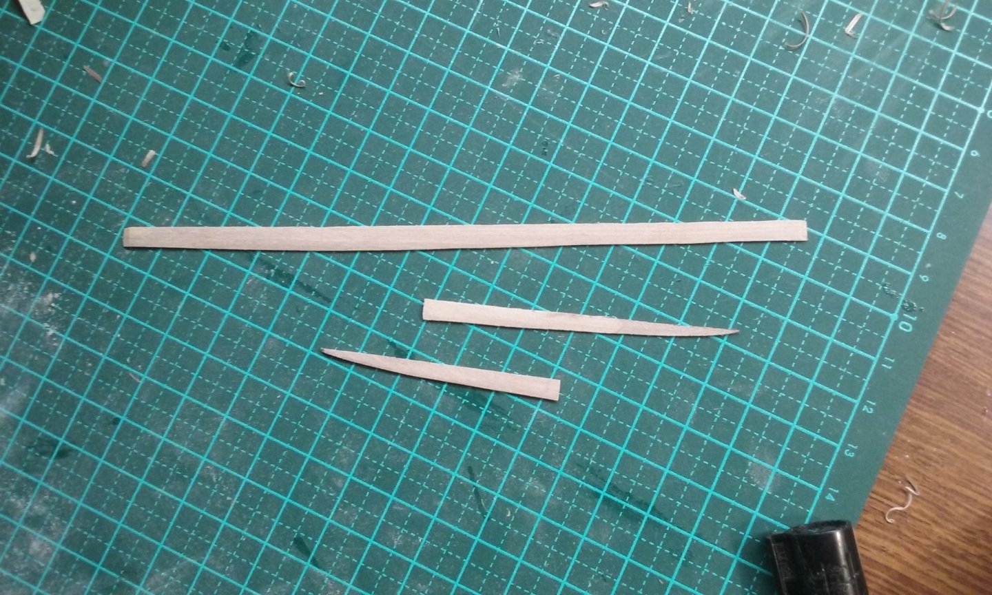
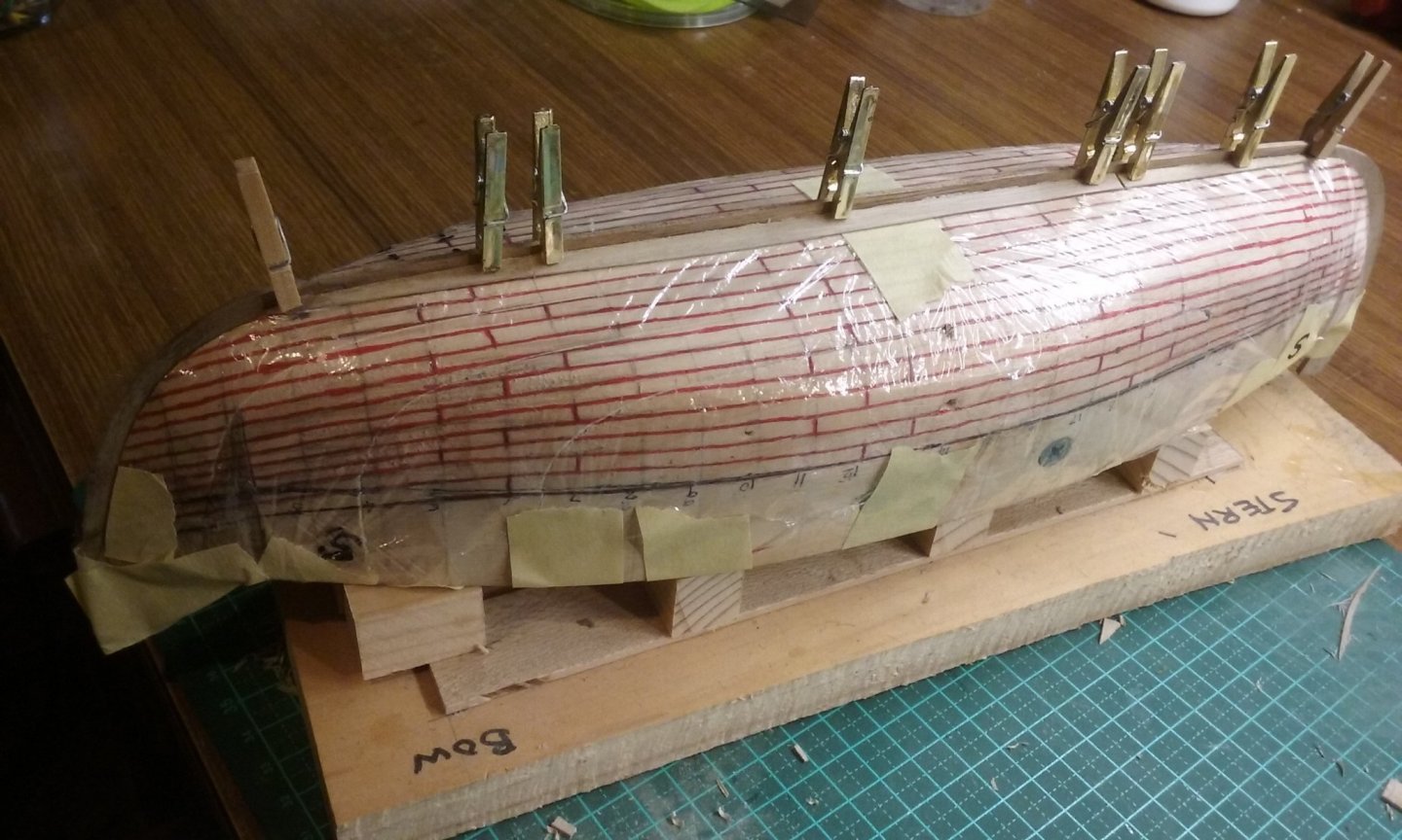
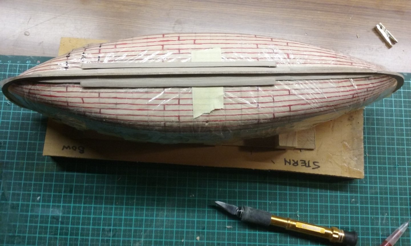
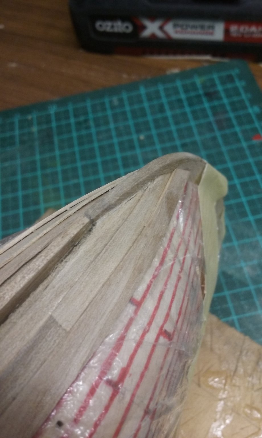
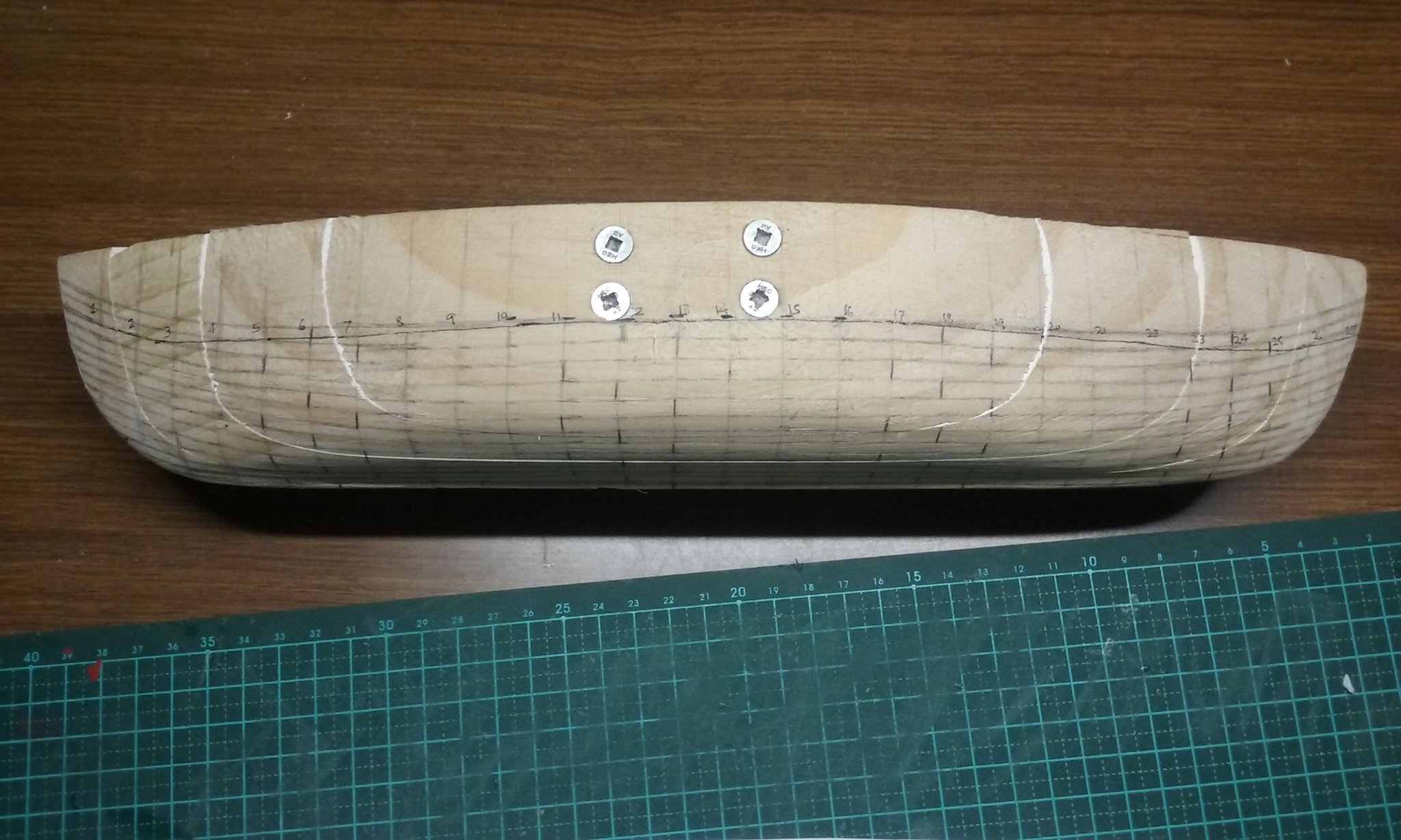
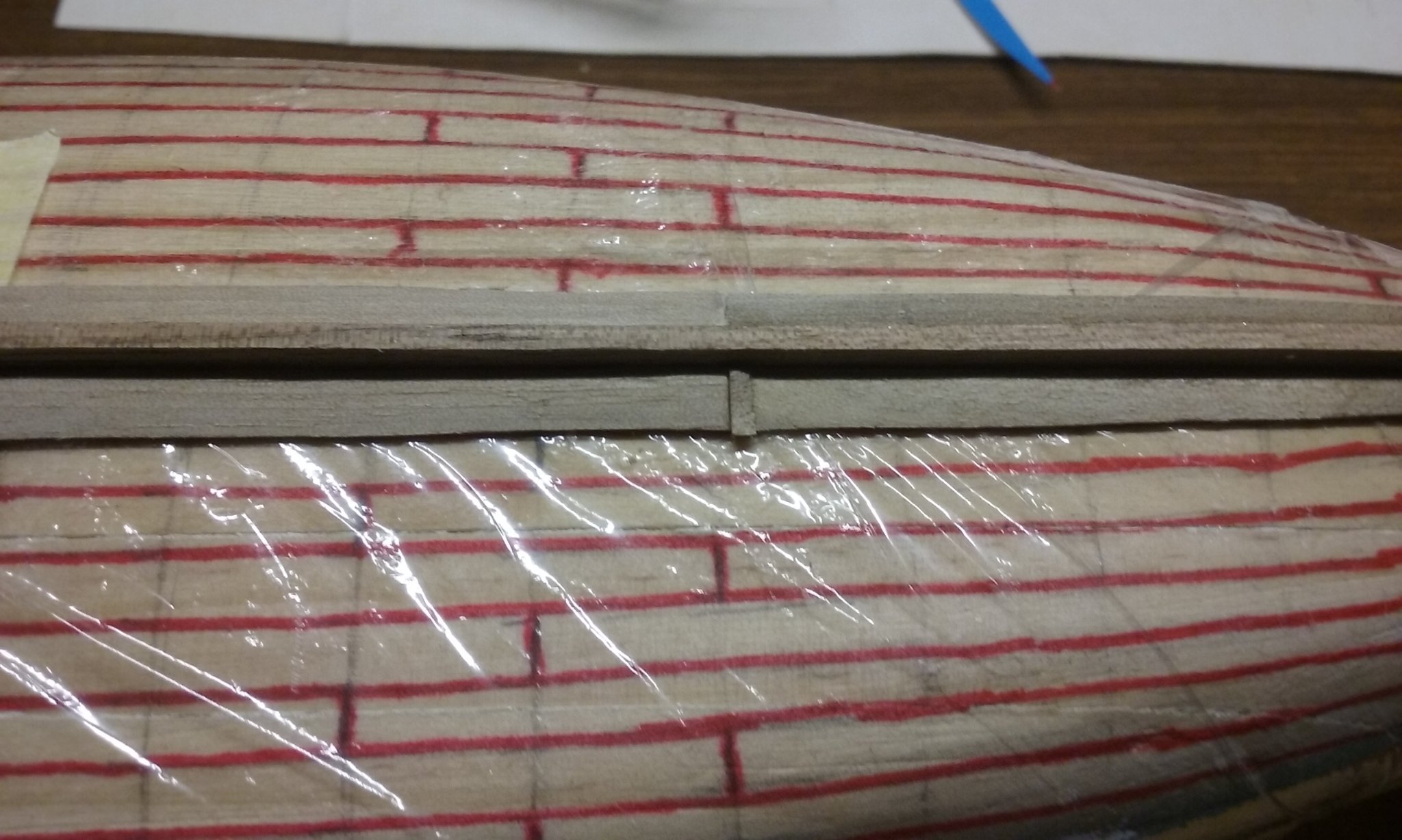
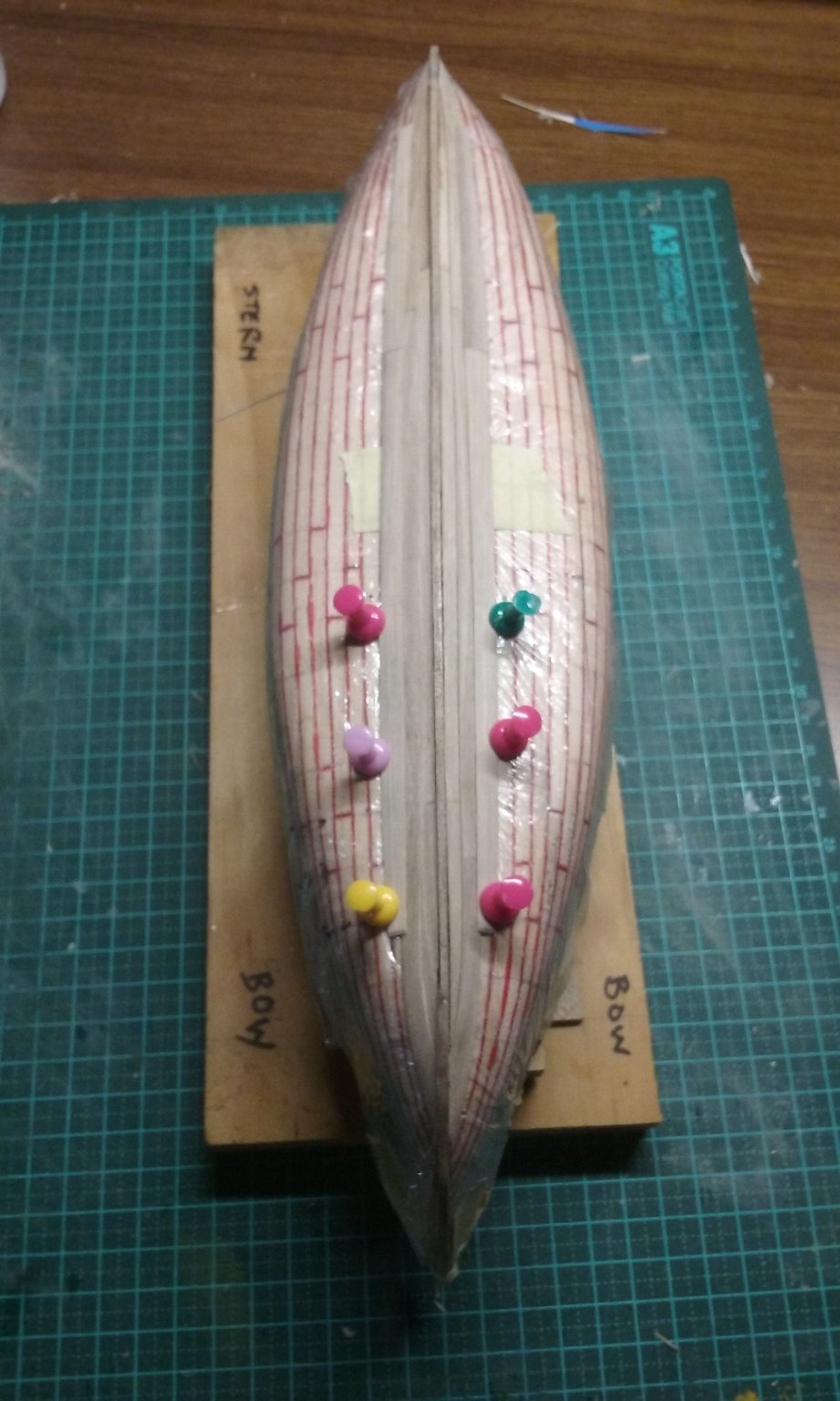
Planking in progress. Note the rubber spaces as recommended by Liteflite (though sometimes I use wooden spacers when stiffness is needed). And a sliver to close up a gap. And trimmed off. More planking: I've been thinking about Druxey's question regarding the layout of the planking butts - it makes sense that the further they are apart the stronger the structure. But only one of my books (Mondfeld) has a diagram showing how they are supposed to be done. And even then I misinterpreted the layout. So now that I've got this far, I've decided to change the layout in future strakes so the spacing is more equal (see the black marks) More to come. Steven


- 327 replies
-
- 14
-
-
New member from Scotland (Falkirk)
Louie da fly replied to Razorbill's topic in New member Introductions
Which one is which🤣 Hard to tell, sometimes . . . Oh, wait! Simple, the sharp end is the bow and the blunt end is the stern . . . Sorry Razorbill. I'll get back in my box now. Steven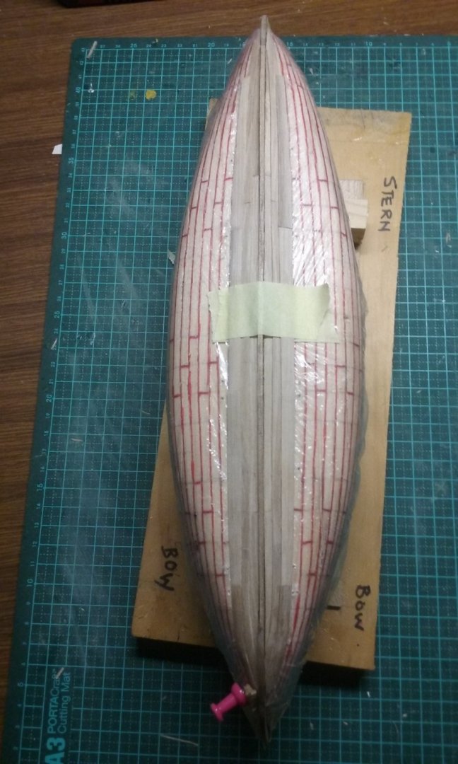
-
Me too. Steven
-
Not that I know of. Contemporary representations just show a 2-shift, with the butts of one strake central to the length of the next, but I think that's likely to be artistic licence and that in the real world there would have been at least a 3-shift. I was trying to get a layout that allowed for the planks to be as near as possible to 20-24 feet, which Mondfeld recommends, while avoiding having the end planks too short, as they seemed to be with any other layout. BTW, to my shame, I got one of the plank shifts wrong, so the two sides other aren't mirror images of each other at one point. But I'm committed now, (planks are already glued in place) so I'll just have to put it down to experience. Steven


- 327 replies
-
- 10
-
-
Yep. Such a waste Steven
-
Is this your first model? The way you introduced the thread makes it sound like it is. In which case I'm even more impressed - that's some pretty nice planking there. By the way, would you be a Kinks fan by any chance? Steven
-
Yep. If your software enables you to draw the planes (and merge them into the main drawing), it should be possible to do your projection lines perpendicular to each plane individually, and so get what when I was learning drafting was called the "true shape" of each frame. Steven
-
You've made a very good start on this, mate. Looking good.
- 50 replies
-
- 2
-
-
- mary rose
- caldercraft
- (and 1 more)
-
Kris, I would treat the plane that each half-frame "sits on" in its own right, as 30 separate entities (i.e 2 for each frame marked in red on the diagram). Then project from the front elevation of each frame, one by one onto the appropriate plane, at right angles to the plane itself. Does that make sense? Steven
-
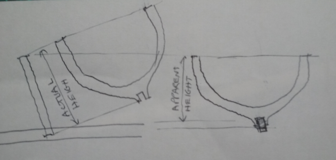
Does that mean the frames are angled from the vertical? Like a raked mast? If so, there is a way to do it by "projecting" lines on the paper at right angles to the frame itself. I hope this isn't too confusing. It's a bit hard to explain clearly. Maybe a diagram will help: But if the angling doesn't change frame width, all you really need to do is proportionally adjust the frame heights (for example, if the angled frame needs to be 10% higher than it appears to be from directly front-on (i.e. at right-angles), increase the height of each point of the frame by 10%.) Perhaps you can "stretch" your drawing in some program like "paint" or photoshop. I hope this helps. Steven
-
Good work on the oars, mate. I know how trying/boring it can be, but they look good. Any chance of some photos of the hull? Steven
-
Welcome to MSW, mate, from sunny Ballarat. Hope you're safe up there. Steven
-
Thanks for the likes and the comments. Chuck, yes I'm spiling. I've only had one plank break so far, but note that the planks are only about 0.8 mm (0.03 inch or 30 thou) thick, and there are no particularly tight curves. The broken plank broke when I was trying to induce a curve in it - I think I tried too hard too fast. Steven
-
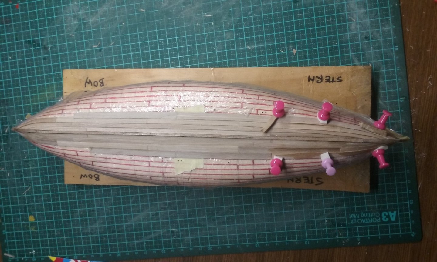
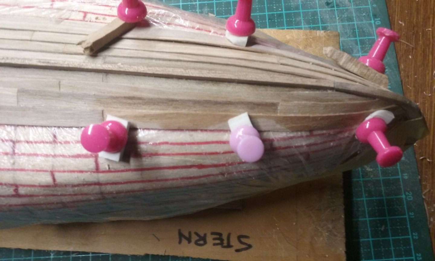
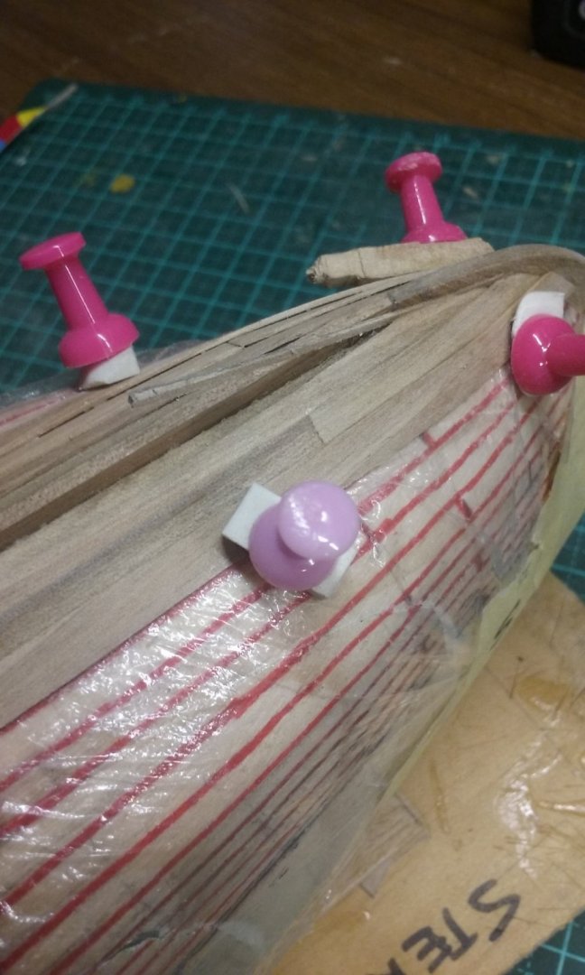
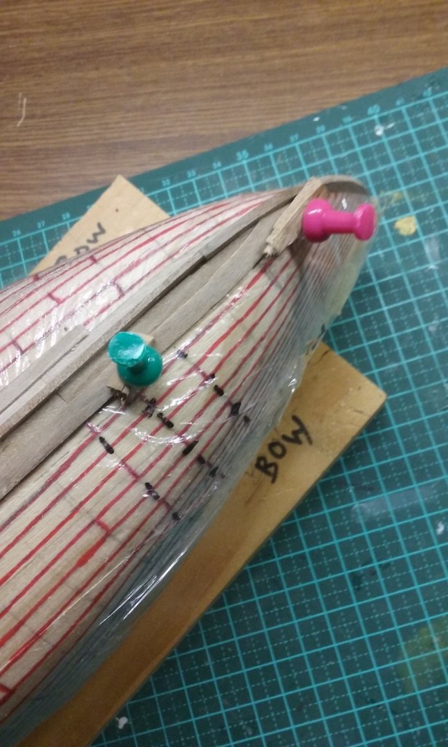
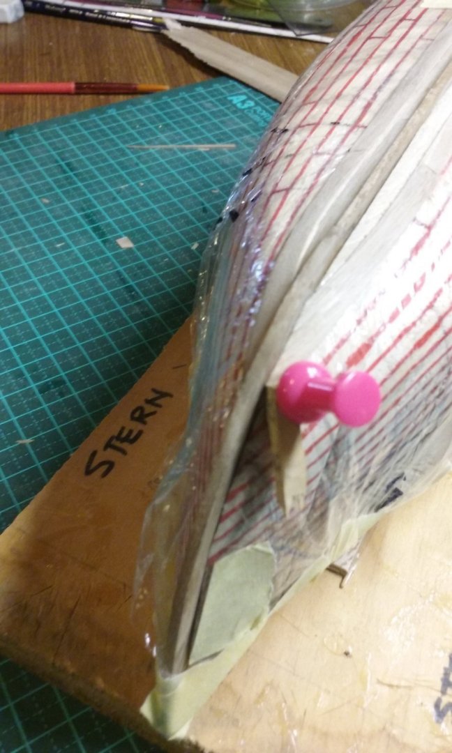
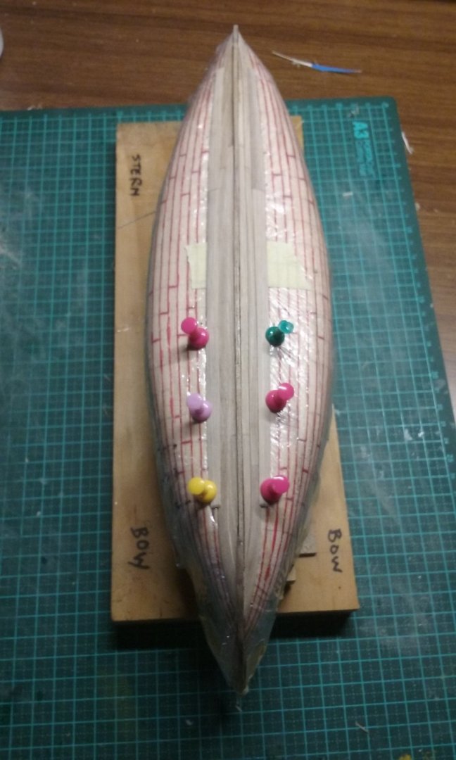
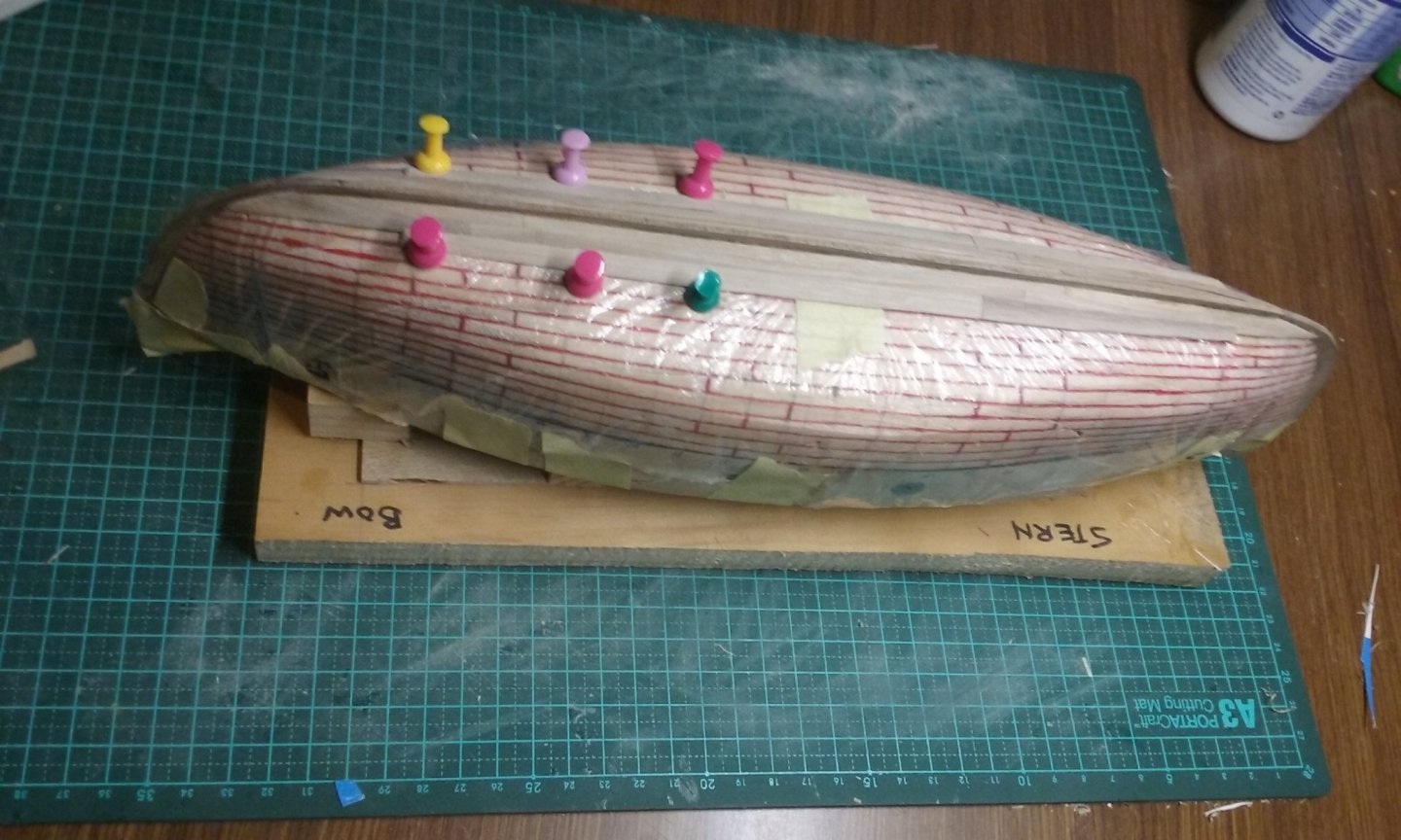
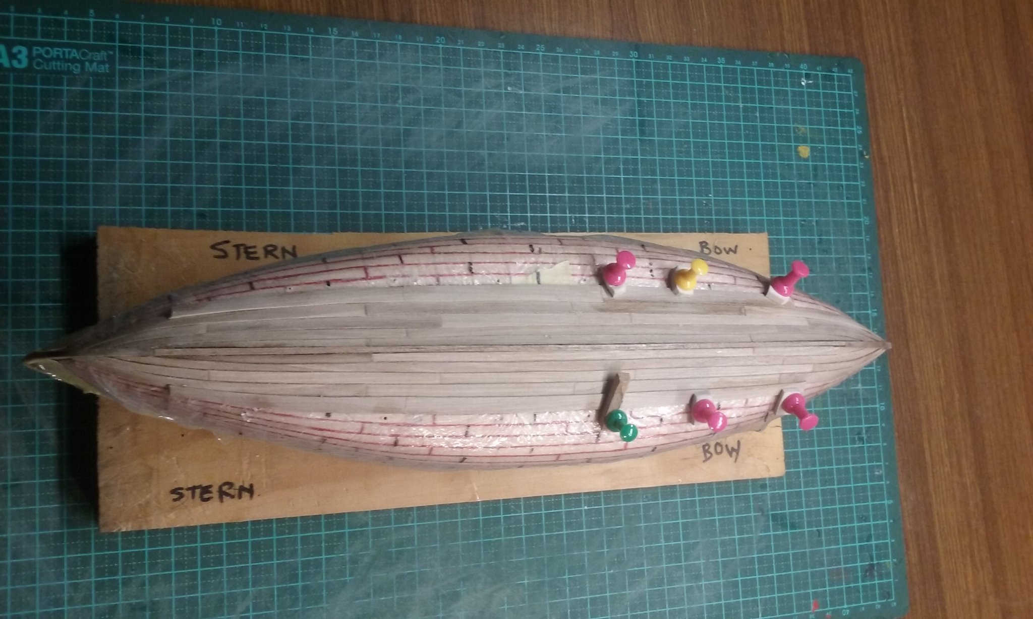
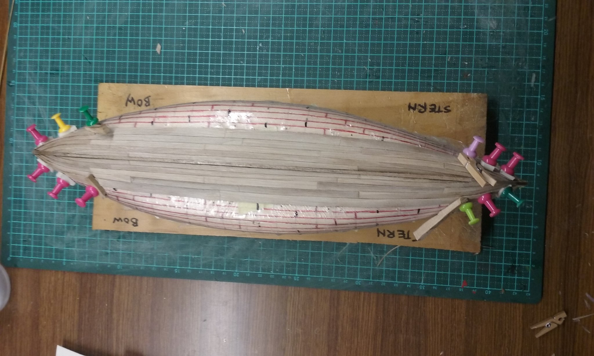
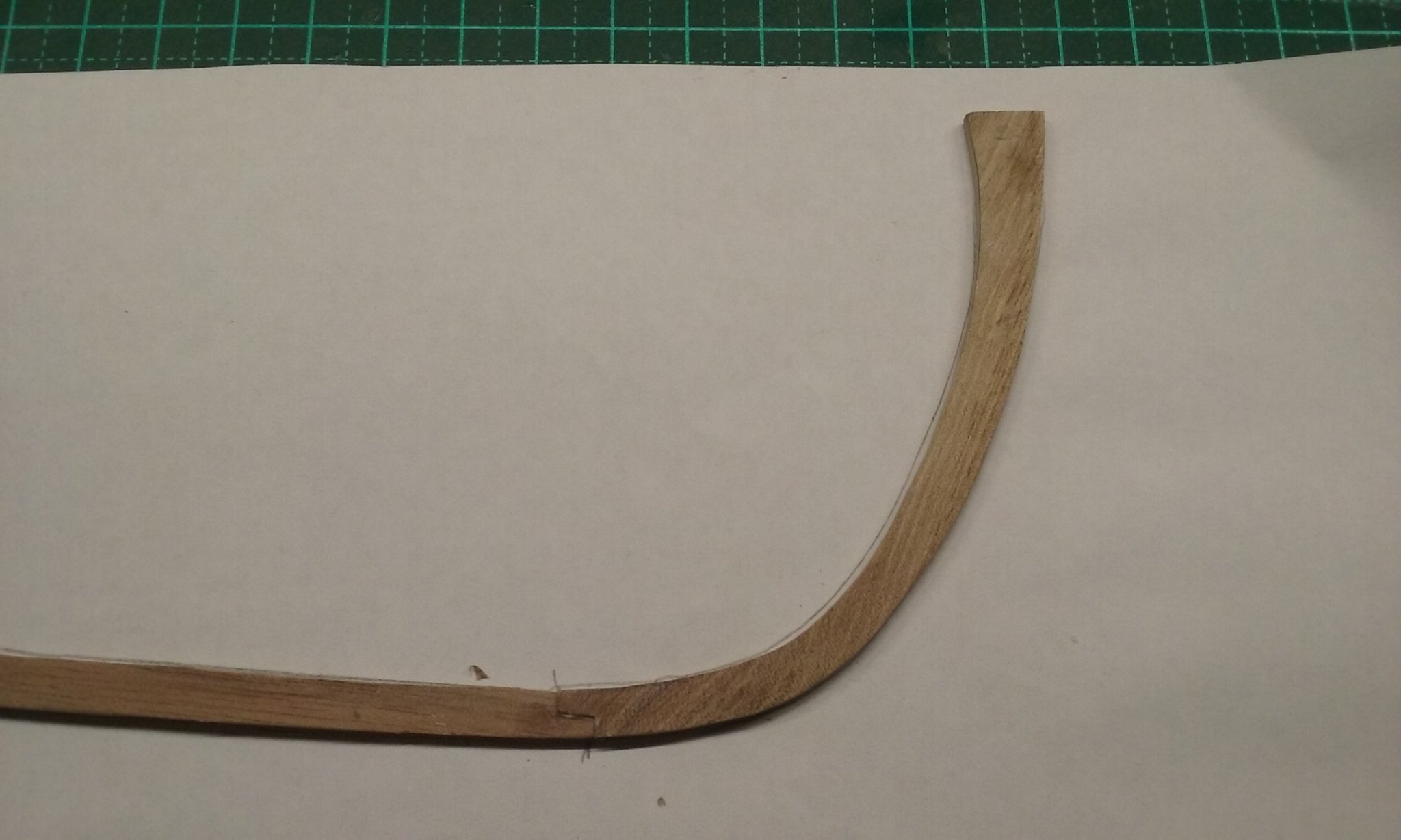
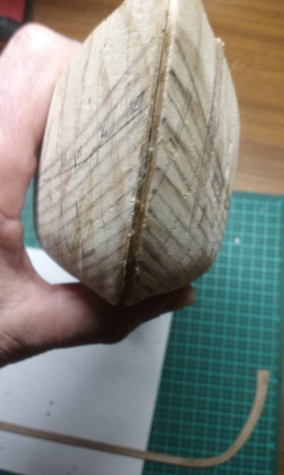
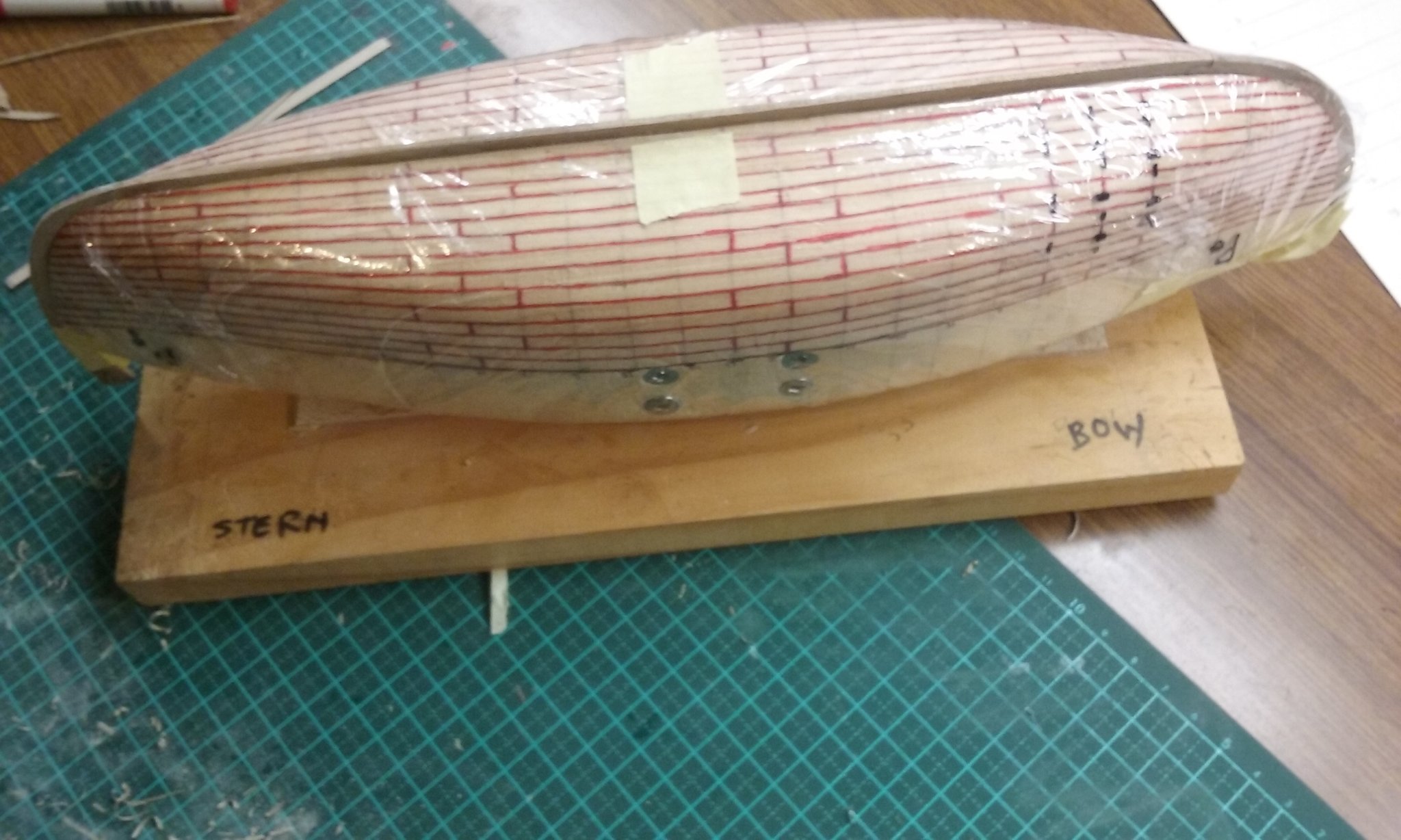
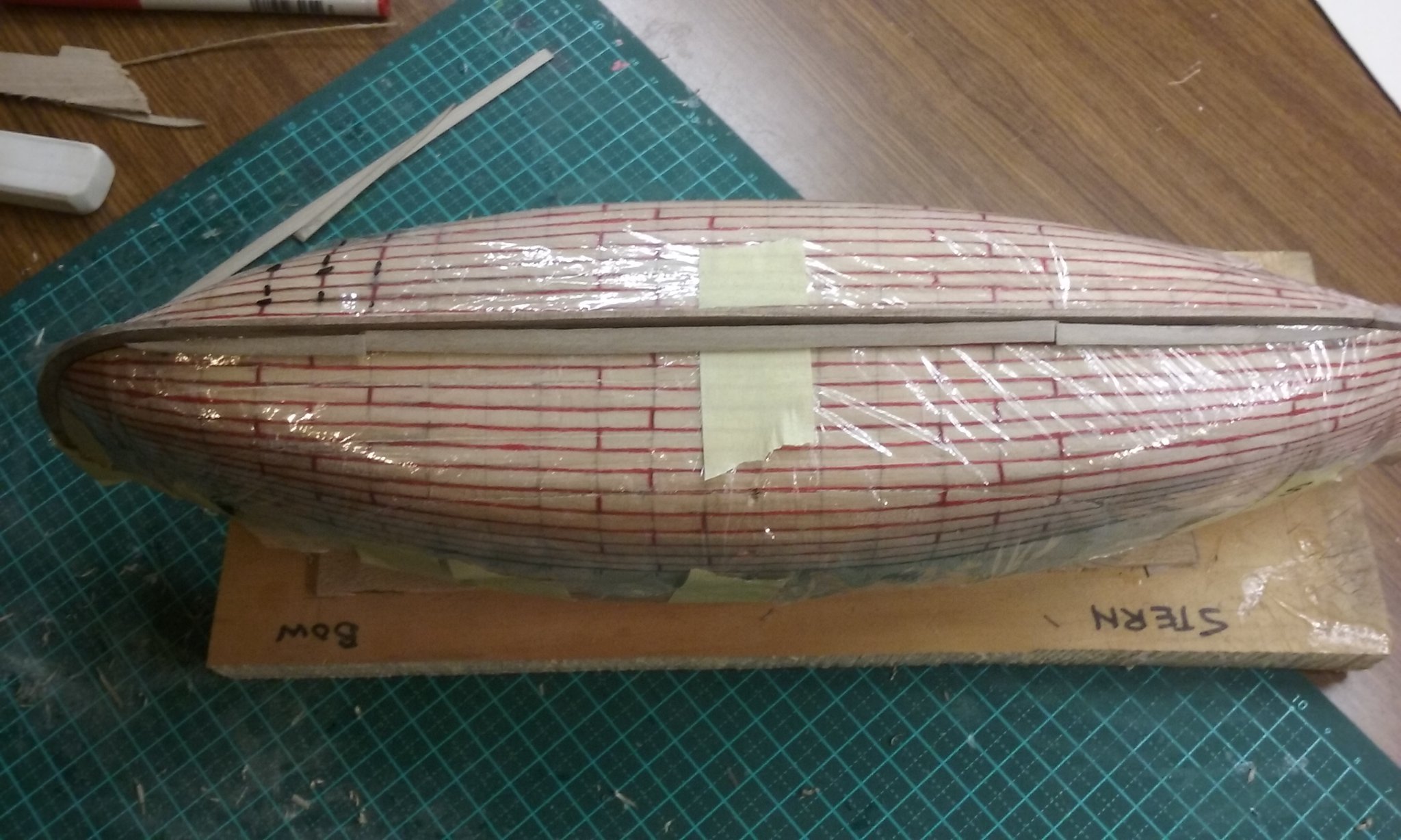
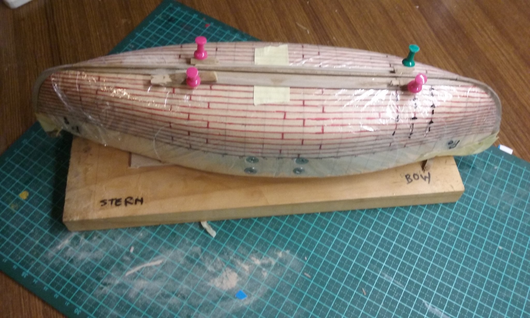
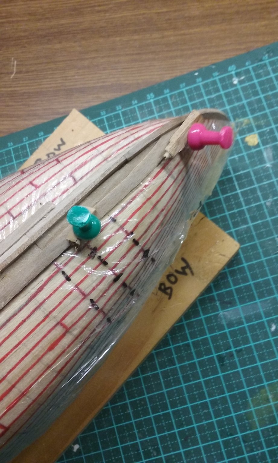
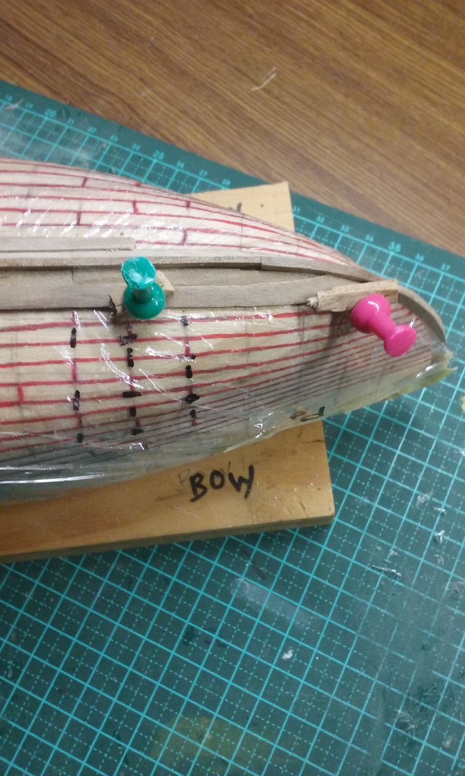
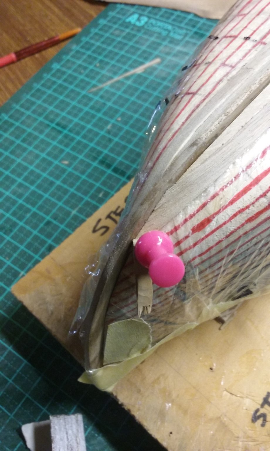
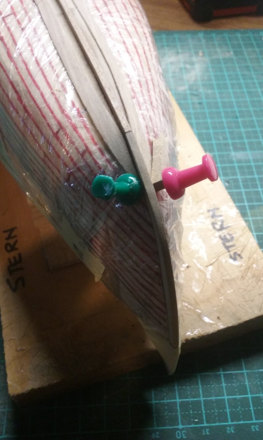
Having decided to "drop" the drop planks the planking came up higher and I found I had to make higher stem and stern posts. I was fortunate that I had some wood with a curved grain to make them stronger. I needed to keep them the same orientation as the old ones, but I only had a scarph joint to keep them aligned. So before I pulled the stempost/keel/sternpost asembly apart I traced over the old set-up and used it as a pattern for the new one. New planking layout marked out on the plug, with the plank shift also marked. And picked out in red to make it easier to see. Cling-wrap on the plug again, to stop the planks adhering to the plug. The planks of the garboard strake. Dry fitted Glued in place. I was fortunate to find a set of tiny clothes pegs made out of plastic instead of wood, so the glue didn't stick them to the ship. The scarph joining two planks didn't quite work, so I glued in a bit of wood to fill the gap; to be sanded off later. And here's the sequence of planking so far: I used push pins to hold the planks down - the plug was made of pine, but it was rather tougher than I'd been expecting, so I needed to drill pilot holes in the plug so they'd go in far enough. And I used scraps of wood to spread the load, or concentrate it as needed. That's it so far . . . Steven


- 327 replies
-
- 17
-
-

-
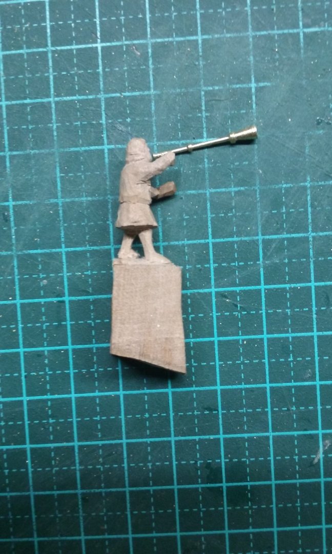
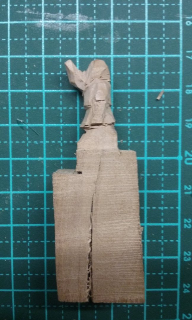
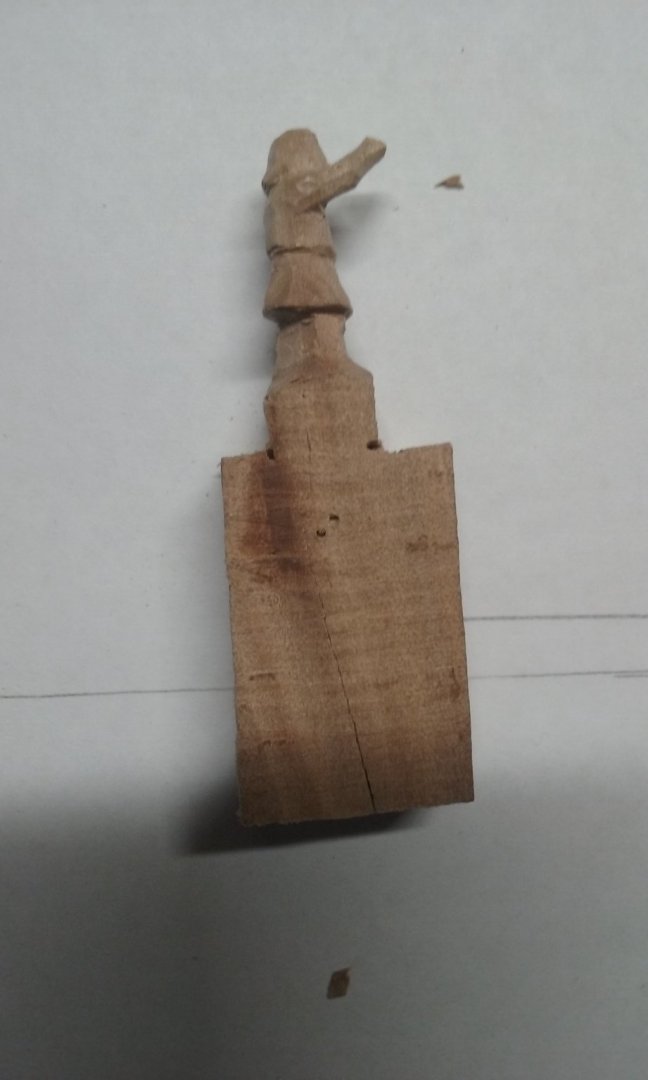
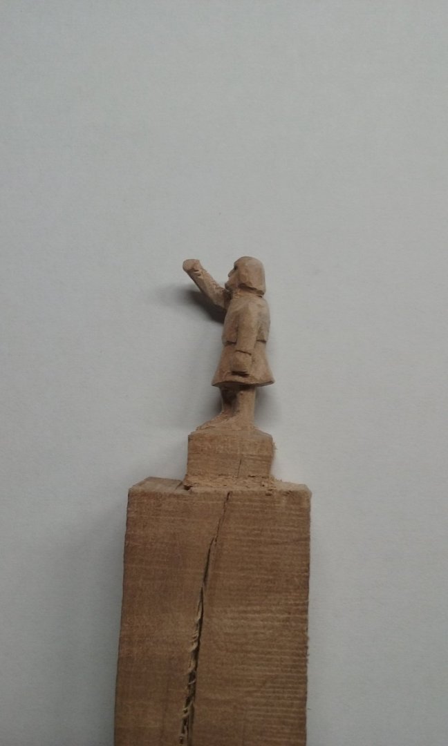
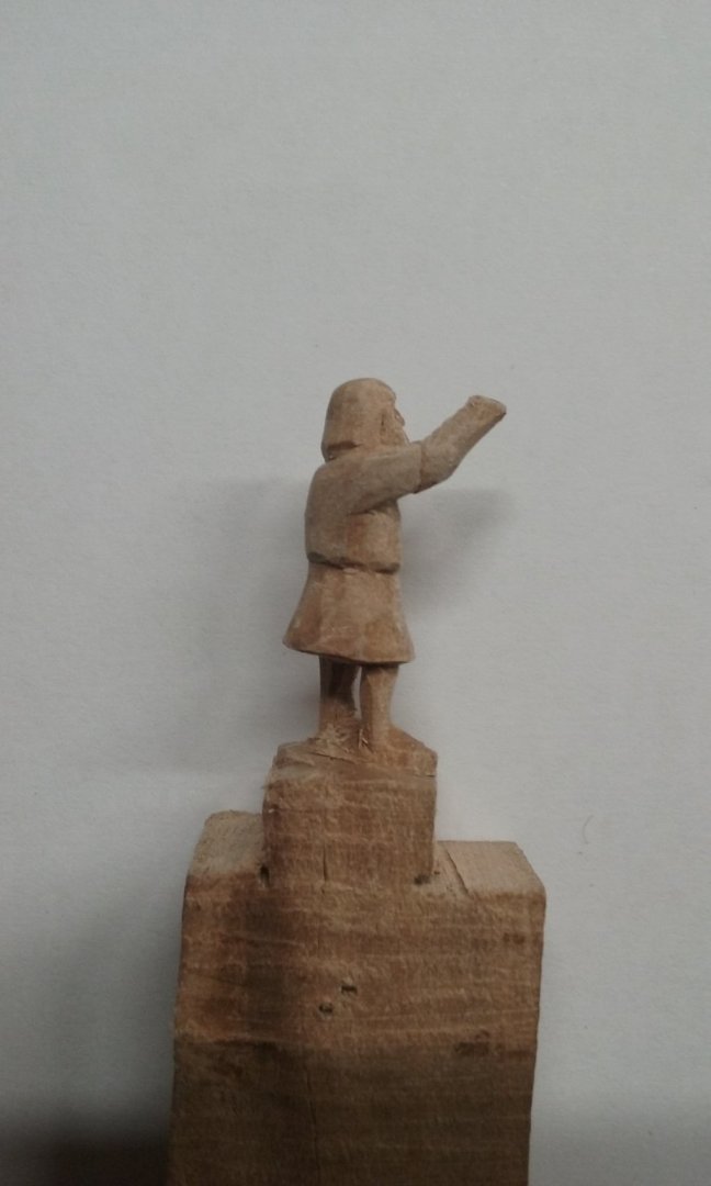
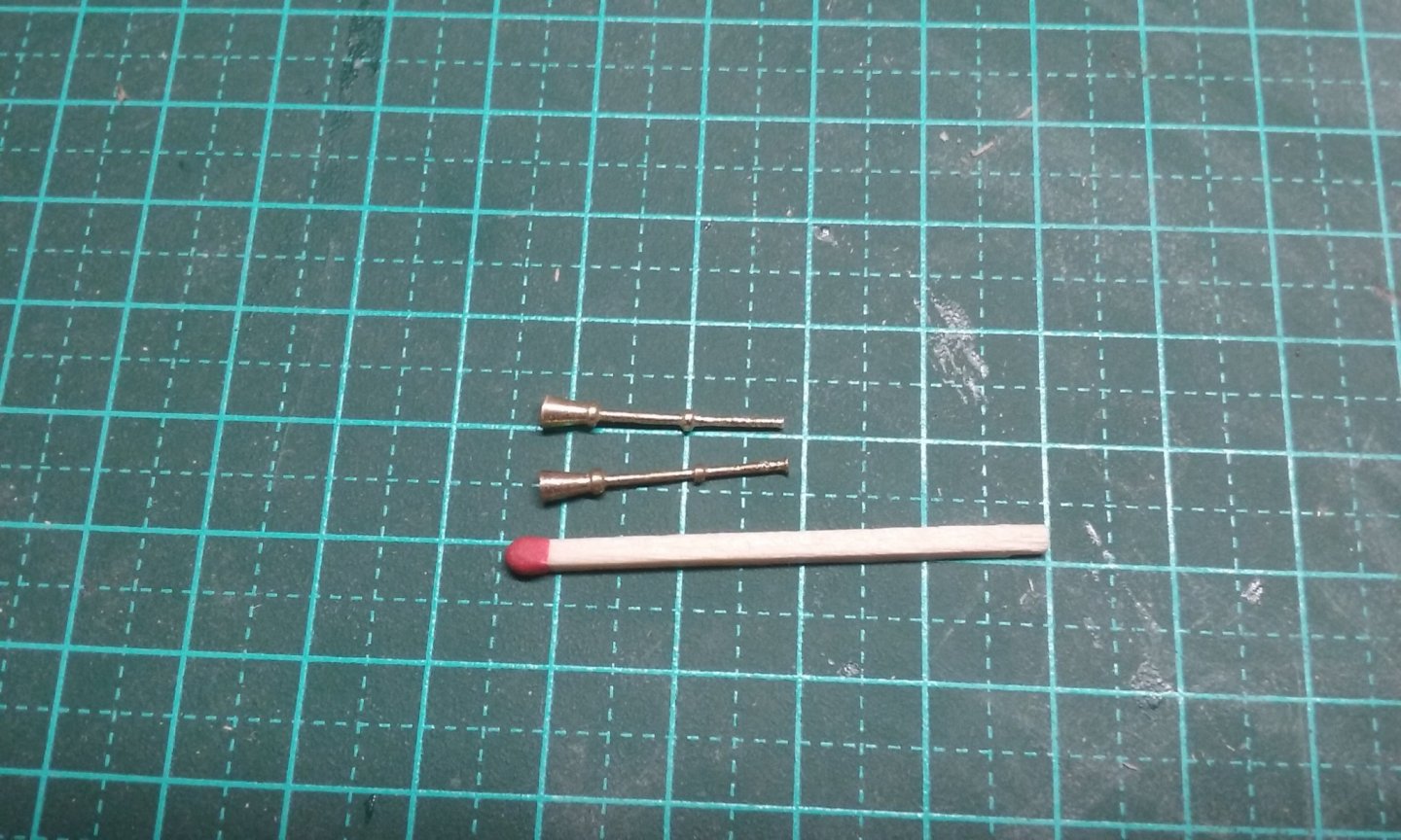
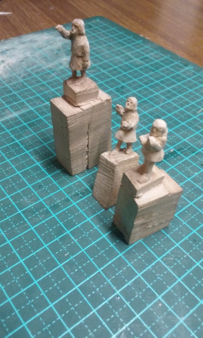
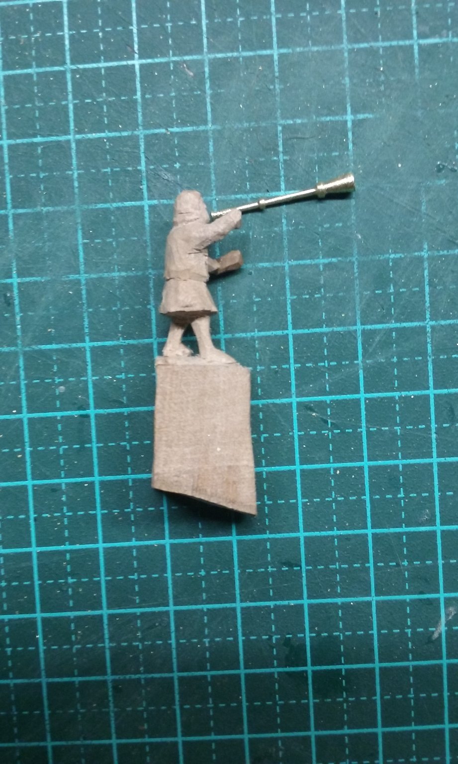
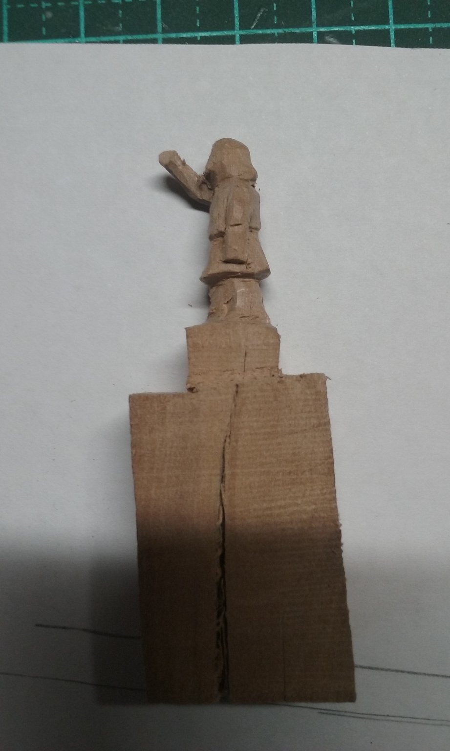
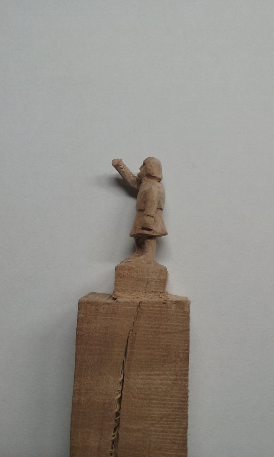
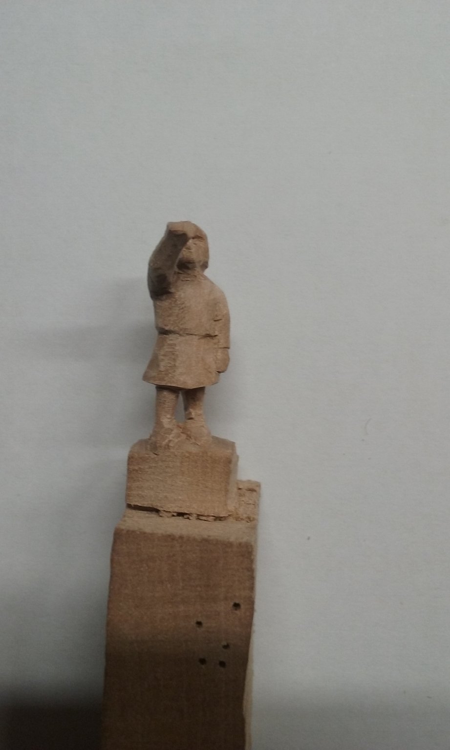
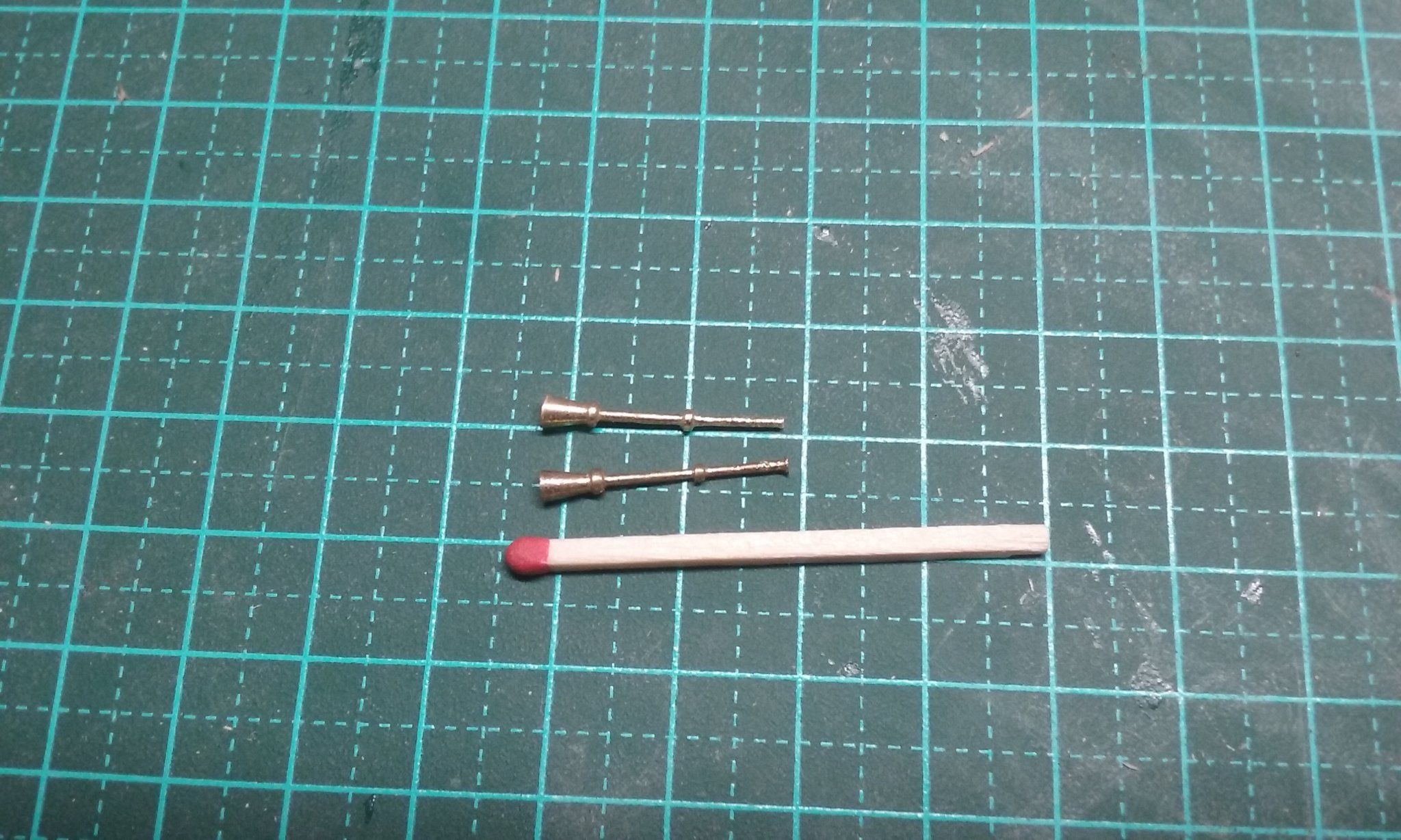
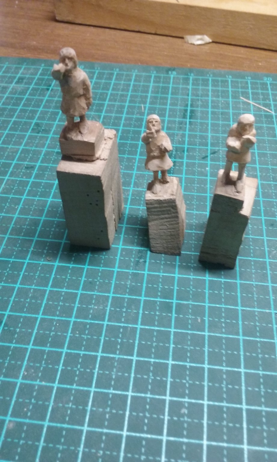
Well, I've been offline for awhile but I haven't been idle. I've made a new buisine (trumpetty thing) with a finer shaft, so it looks more like a trumpet than a bazooka. And a second one. Terribly worried I was going to cut the shafts so thin they would break, but they turned out ok. And I've carved the second buisinier, so now I have both. So here's the three figures so far - A and B on the seal below - (the helmsman isn't finished - I won't finalise his arms till I have the steering oar made and in position) The next people to carve will be the guys amidships (C on the seal). And looking carefully at them for the first time I realise they are working a windlass! It turns out this seal is not just a picture of a ship - it's captured a moment in time! This ship is getting ready to set sail: The helmsman (A) is in place to steer the vessel, and two buisiniers (B) are announcing the ship's departure. The windlass (C) is raising the yard , two crewmen at the bow are weighing in the anchor (D), another crewman (E) is climbing a backstay to unfurl the sail when the yard is fully hoisted. Steven


withcircles.thumb.jpg.44182fb98650a9cc3a9722029307715b.jpg)
- 327 replies
-
- 15
-
-

-
She looks magnificent! Steven
-
Hello from Texas Longhorn Country
Louie da fly replied to Glen McGuire's topic in New member Introductions
Glen, Welcome to MSW. Just looked through your build log. Very impressive. Steven -
Glen, that's a really impressive model, particularly as a first build! A couple of points for future models - the standing rigging (shrouds, stays, ratlines) were tarred to protect them from the weather (actually the ratlines probably weren't but would have absorbed tar from the other ropes) and would have been black - or actually dark brown. The running rigging wasn't tarred, as it had to pass through blocks etc, so would be the natural colour of the rope (though it tended to fade and was closer to off-white than tan). You might like to investigate the use of silkspan for sails - it's much closer to scale thickness and fine-ness of weave (in fact it's not woven at all). See and And for sail/steam ships, you might like to look at Banyan's brilliant scratch-build of HMCSS Victoria - see Congratulations on completing a very impressive build! Steven
-
New member from Scotland (Falkirk)
Louie da fly replied to Razorbill's topic in New member Introductions
Please Glenn - at least use the correct terminology - "Sharp end" and "blunt end" On a more serious note, welcome to MSW, Razorbill! Take your time - it's not a race - both deciding on what you want to build, and building it. I'd second the comments above - start simple, but don't be worried about making mistakes - we all do - the more experienced modellers just make more interesting ones. Good to have you aboard. When you get started, begin a build log - not only so we can see your model as you progress, but it's also a great way to ask questions and get help and advice from other members, who may well have encountered the same problems. Steven


withcircles.jpg.1dd66da61f69e284e200c4f9e6afe909.jpg)