Louie da fly
-
Posts
7,990 -
Joined
-
Last visited
Content Type
Profiles
Forums
Gallery
Events
Everything posted by Louie da fly
-

Chain Plates Gor 16th Century Spanish Galleons
Louie da fly replied to Bill Jackson's topic in Masting, rigging and sails
I've just added some more galleons to my Pinterest page, for those who are interested. https://www.pinterest.com.au/lowe1847/galleons/ Steven -
Merci beaucoup, GD. For the English-speakers; "The carlingots are two pieces placed against the keel, parallel to it, for lateral reinforcement. The aiguillettes are the top piece of the top part of the cavaliers (which on this ship have a particular form)". I'm not familiar with the term cavalier, but it seems to be a frame, and so I think the aiguillette must be the top futtock. Steven
-
Hi Sandra, What an amazing job to have! I envy you immensely. I have a smattering of French myself, which has helped me with archaeological reports. Speaking of which, have you any idea of what is meant by the terms aiguilette and carlingot ? (see text below from the report Le Navire Génois de Villefranche in Archaeonautica No. 9). The carlingot appears to be something to do with the carlingue (keelson) but I can't find a definition for it anywhere. Any help gratefully received. Steven
-
Chain Plates Gor 16th Century Spanish Galleons
Louie da fly replied to Bill Jackson's topic in Masting, rigging and sails
Thanks, Allan. I think there's a lot to learn from contemporary representations, and I thought it would be good to collect as many as possible in one place as an easily-accessed reference. Bill, just a quick question - when you ask about chain plates, do you mean metal plates or the flat wooden extensions to the hull which hold the shrouds, known as chain wales (channels)? Steven -
Chain Plates Gor 16th Century Spanish Galleons
Louie da fly replied to Bill Jackson's topic in Masting, rigging and sails
You might like to look at the collection I made of contemporary representations of galleons at https://www.pinterest.com.au/lowe1847/galleons/ - it might be helpful. Steven -
Beautiful work, Slog! I don't know how anybody manages to produce such magnificent work from card. Kudos, mate! Steven
- 244 replies
-
- 3
-

-
- borodino
- dom bumagi
- (and 1 more)
-
Sandra, you'll occasionally find that there are alternative translations between French and English, of which one is correct and the other isn't. For example the usual translation of the word pont into English is "bridge" - but the correct word for ships is "deck". The "bridge" is a different part of the ship entirely. Another one is bâtiment - the usual English translation is "building", but the maritime one is just "ship." There are quite a few words like this, but as you get into the subject it gets easier. Steven
-
Antony, I really regret never having taken photos of Great Harry (Henry Grace a Dieu) when she was in her original glory. I had all the masts in, all the sails, all the planking, the decks, almost everything except the rigging. It would be nice to compare that with the way she is now. Your photos are pretty amazing. It'll be interesting to see how the new one turns out and following on as she progresses. There is certainly some amazing work on MSW, but it caters for everybody from the rawest newbie to the demi-gods of ship modelling, who write text books on the subject. You'll find the people here very supportive and helpful no matter what level a person is. In my view this is the best forum on the Net. Steven
-
Welcome to MSW, John. That Armed Virginia Sloop is a beautiful model. You've done a lovely job. You're not alone in making mistakes - we all do it - but as you say they are very often a learning opportunity, and fortunately wood is a very forgiving medium. Good to hear you'll be making a build Log for your Rattlesnake, but in the meantime if you want to start one your Fair American - particularly if you have photos to enable you to do a retrospective log - I'm sure we'd all be very interested. Good to have you aboard, mate! Steven
-
Hi Antony, and welcome to MSW! So sorry to hear about your model being destroyed - it was a beautiful vessel. I'm in a similar situation, in a way. Back when I was 17 I built a scratch model of the Henry Grace a Dieu (Henry VIII's biggest ship) , then pulled it apart because I wasn't happy with the shape of the stern. Then life got in the way - I moved to the other side of Australia, so the model got neglected and steadily deteriorated in its cardboard box. Quite a few of its original pieces - the figurehead, the longboat, the shields along the sides - got lost along the way. About 50 years later I started restoring her and I'm still in the process of doing so. At least in my case it was only neglect, not destruction, so I was able to work on the same model to get it back up to scratch. Looking forward to seeing your new model taking shape. Mediaeval ships are a particular favourite of mine. Good to have you aboard. Steven
-
Bienvenue! I am not certain whether you want modelling or maritime terminology. There are several online translation resources for maritime terms. I particularly like this one - https://archive.org/details/dictionnairedes00tiregoog/page/n12/mode/2up - it contains very many terms useful in modelling. However, it translates only in one direction - from French to English. But I hope this is helpful. Are you planning to realise a ship model yourself? Steven
-
Ancient galley rams discovered - photos
Louie da fly replied to Louie da fly's topic in Nautical/Naval History
Ancient vessels were built "shell-first" - either without frames or with frames added after the planking was completed, and the planks were held together with tenons in mortises within adjoining planks, pinned in place with dowels. (from https://en.wikipedia.org/wiki/Phoenician_joints ) According to Prof John Pryor's book Age of the Dromon the waterline ram was designed to break the tenons so the planks separated, letting the water in. Later (mediaeval) ships were built frame-first, and it is believed this structure was too strong for the waterline ram to have the same effect, and the "ram" moved upward to become a "spur", which it is proposed was intended either to capsize the enemy vessel or break its oars (or perhaps both). I suppose the test model(s) will be constructed the first way. Steven -
Thanks, Mark. Now I need to sit down and try to absorb the pictures and get my head around them. Steven
-
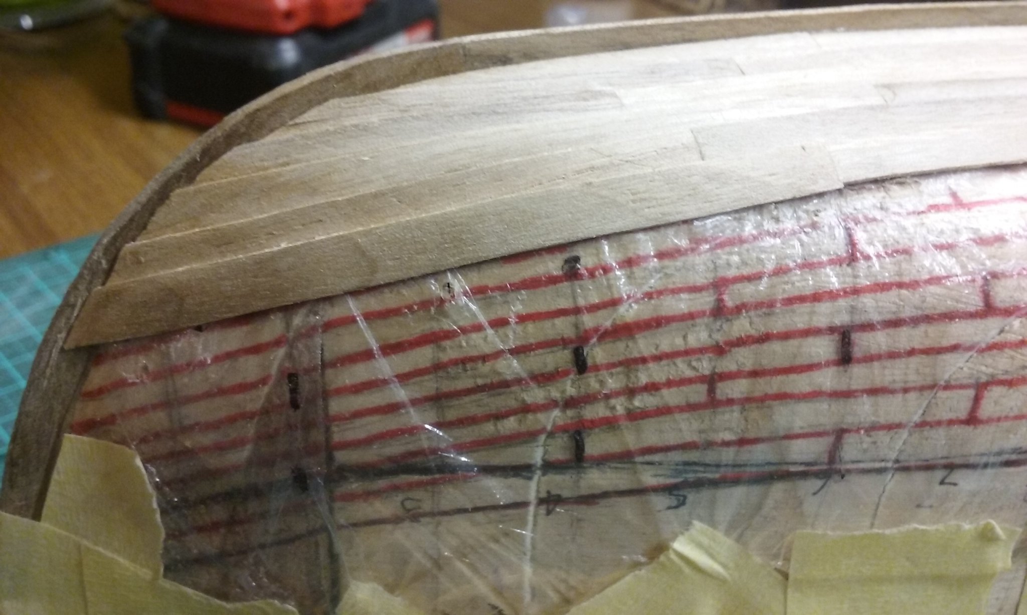
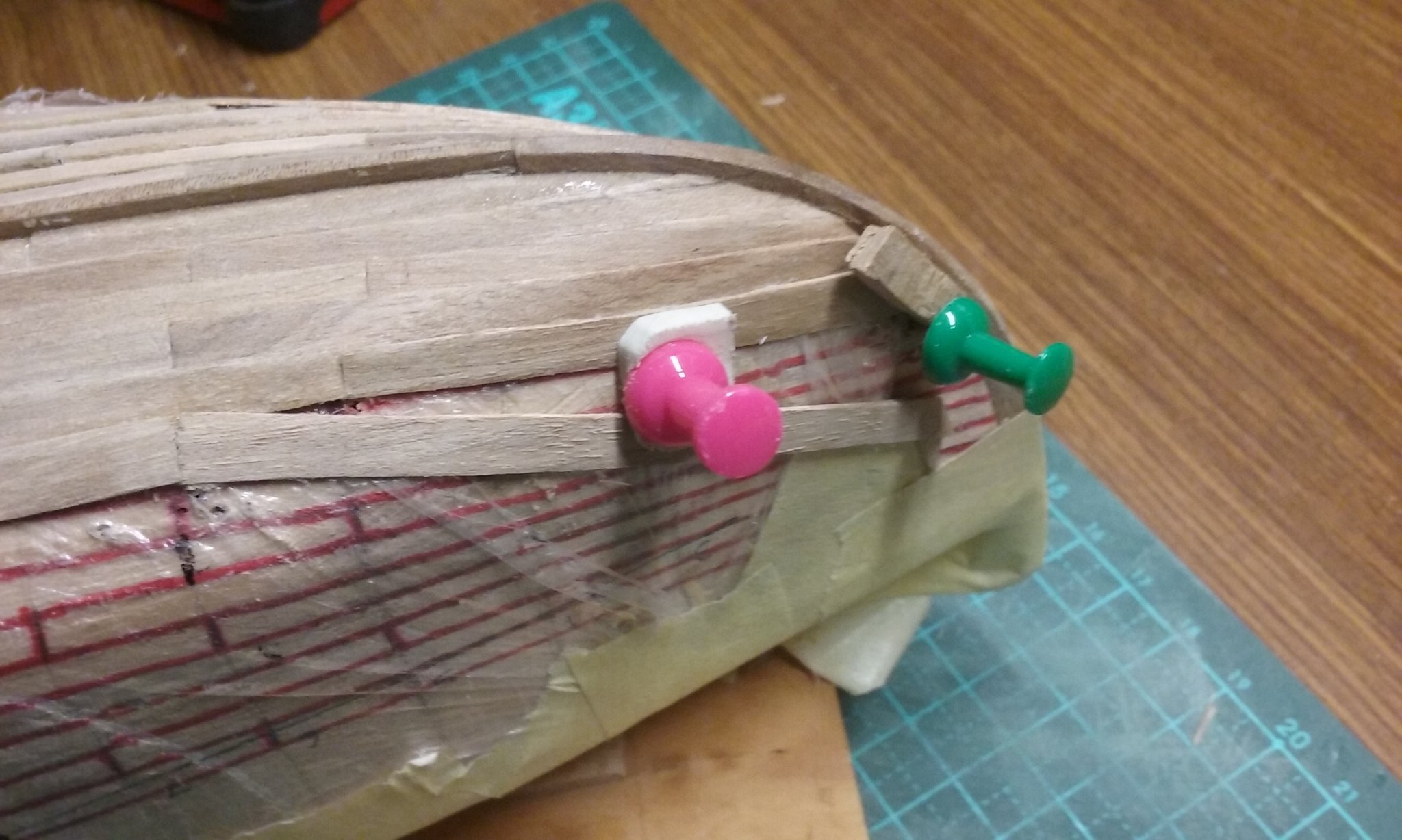
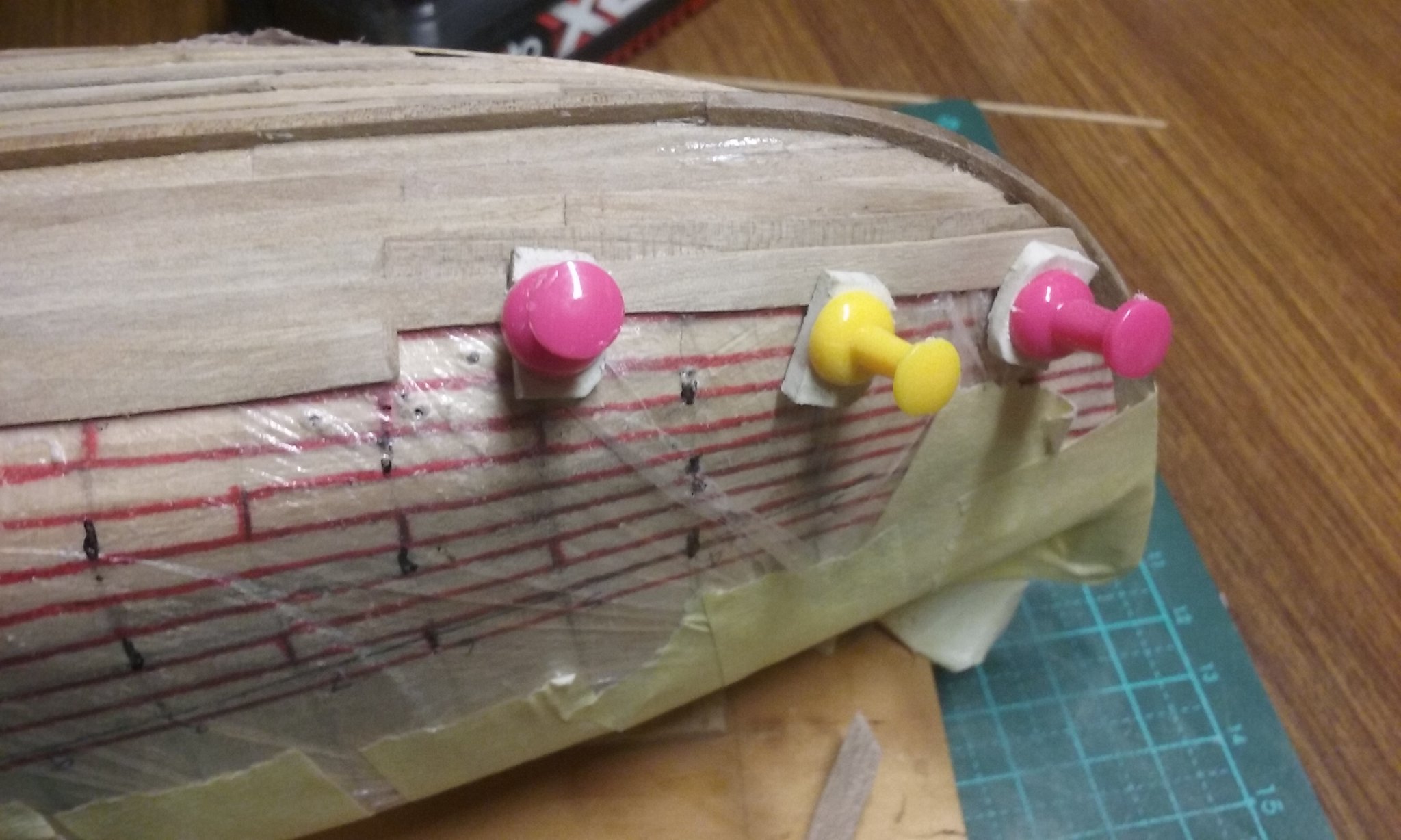
Firstly, thanks everybody for the likes and comments. Druxey, your comments are very welcome, not a pain at all. They do make me think about things that would otherwise not occur to me. Unfortunately, I couldn't open your attachments - they seem to be in Photoshop, which I don't have. I'm not really sure what I'm doing and whether it fits with either of the methods you advise, but somehow it now seems to be working (!) - see the two most recent planks at the bow. And I have to say, I'm really liking the look of this clinker planking. Steven

-
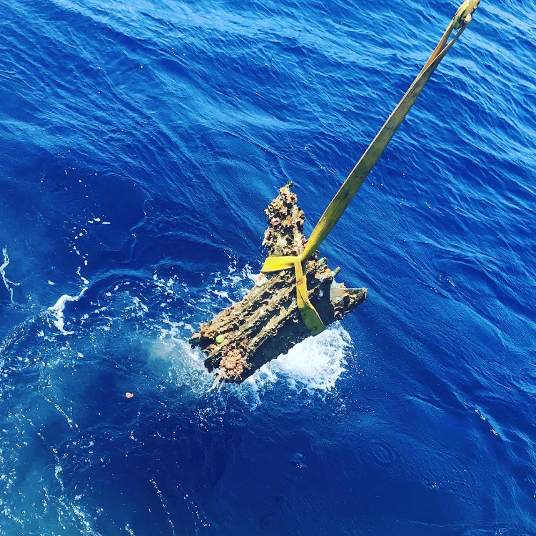
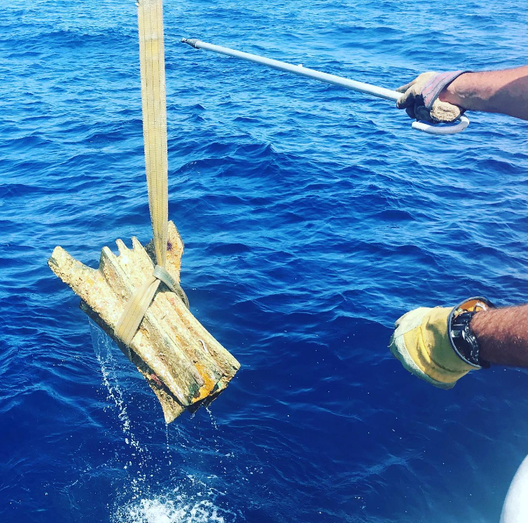
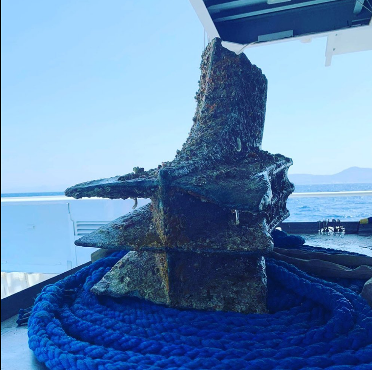
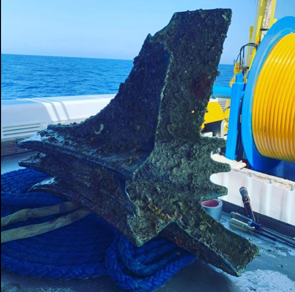
I found this on the Roman Army Talk forum on Facebook: "Latest news from the maritime archaeologists working at the site of the Egadi Islands (Aegates Insulae) naval battle fought in 241 BC between the fleets of Carthage and Rome during the First Punic War. Two new naval rams were recovered from the seabed at the Egadi Islands by the Soprintendenza del Mare, RPM Nautical Foundation, and The Society for Documentation of Submerged Sites divers. The total number of rams at the site is now 25. The raising of these rams highlights a successful, collaborative field season. Egadi rams 21 and 22 will be conserved and housed at the Ex Stabilimento Florio delle Tonnare di Favignana e Formica." A post from another contributor - "Polybius (1.20.1-16) states that the Roman navy in the First Punic Wars consisted of quinqueremes abd triremes. The Carthaginian navy, which was far more experienced consisted of quadriremes and quinqueremes (though possibly with some triremes)." These rams were hollow, as can be seen from the following two photos: This would make sense - apart from the amount of bronze you'd need and the effect of all that weight up at the bow, otherwise how could you fix the ram to the ship so it wouldn't come off? For more information on this archaeological "dig" see https://rpmnautical.org/projects/ancient-naval-warfare/?fbclid=IwAR3Em5kxk-2N9LcSGrCN7_--ZCOVRgGKtDbmZmft7llhRYi79AkTOx3hWN8 Steven
- 28 replies
-
- 15
-

-
-
This is such beautiful work, Rodolfo. Steven
-
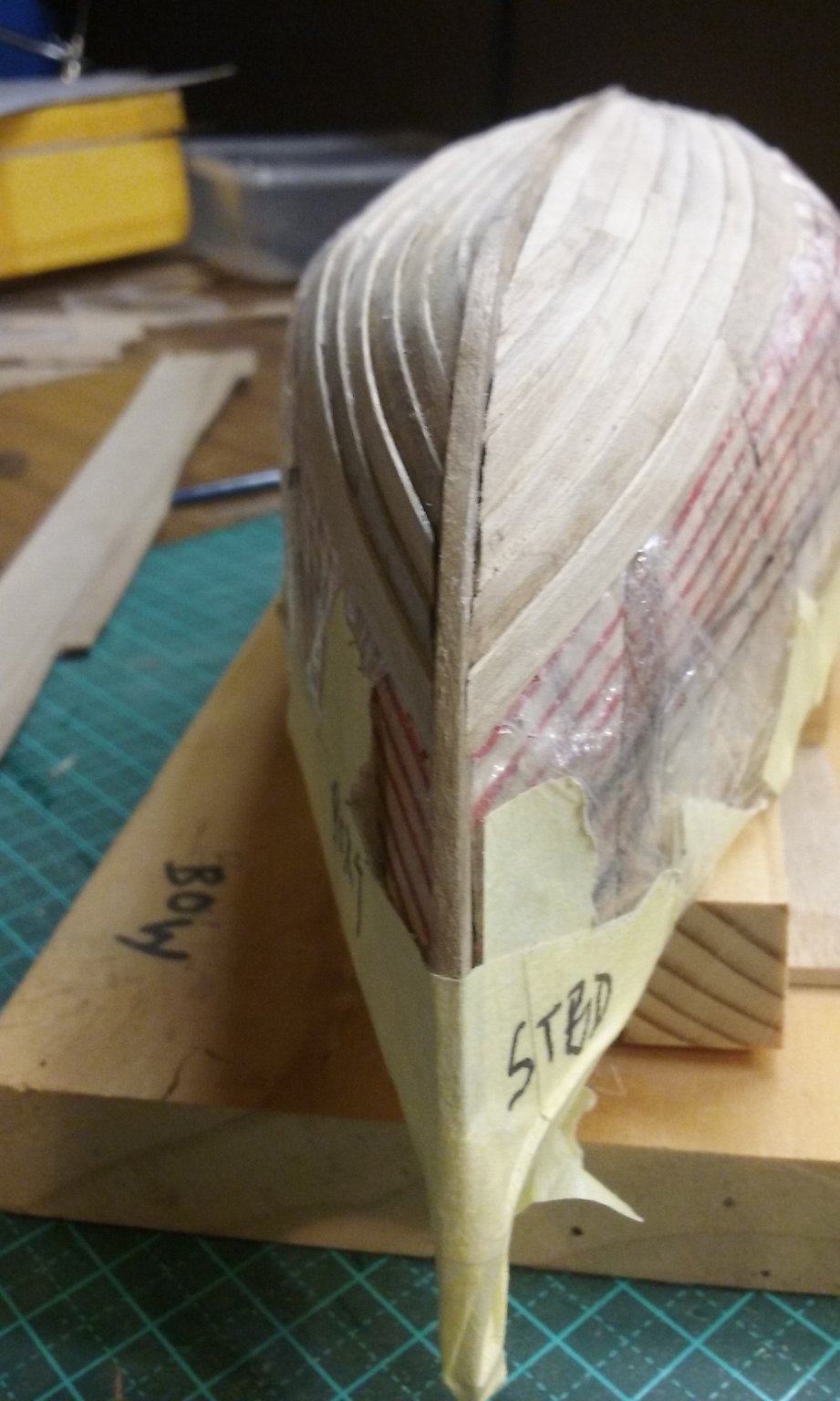
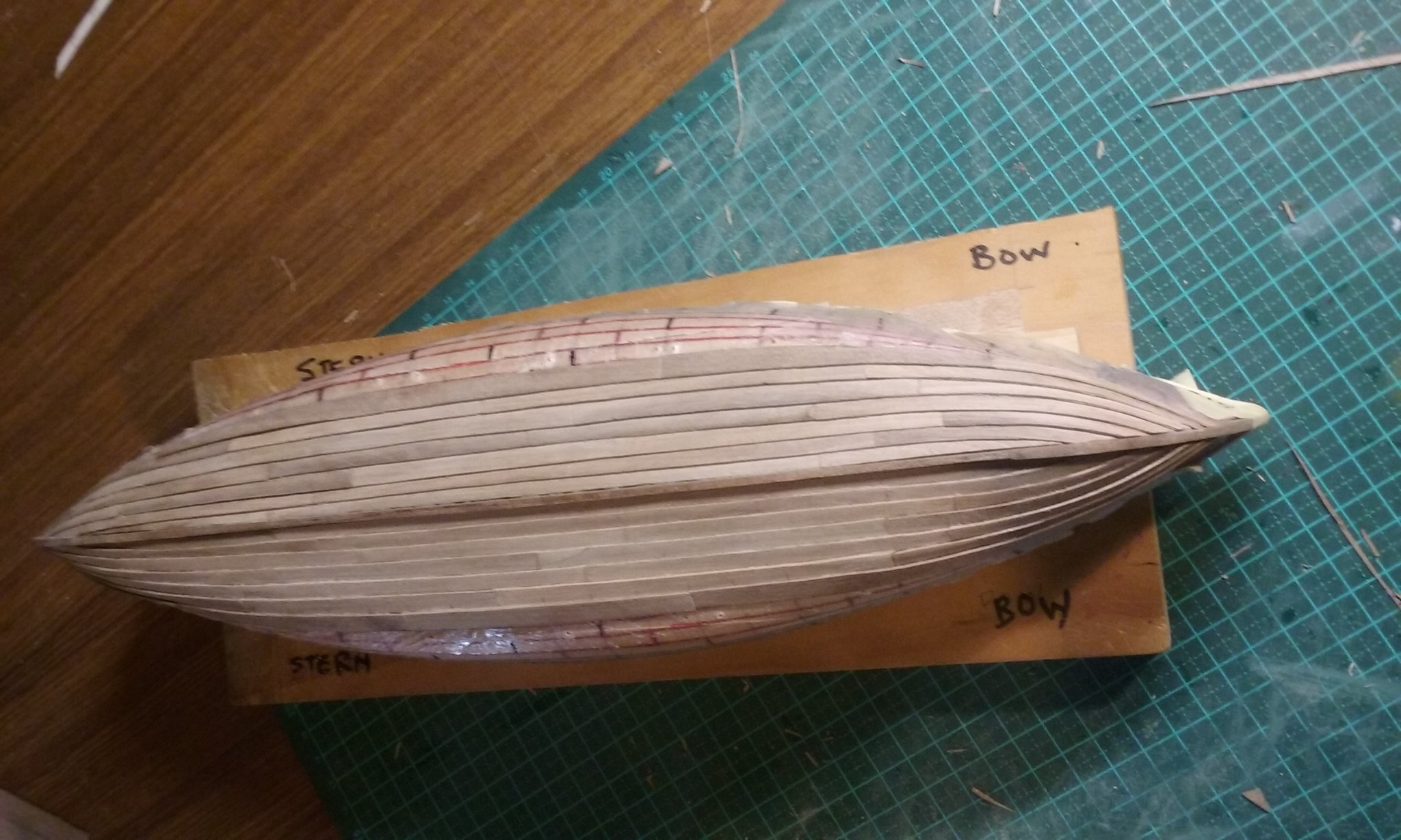
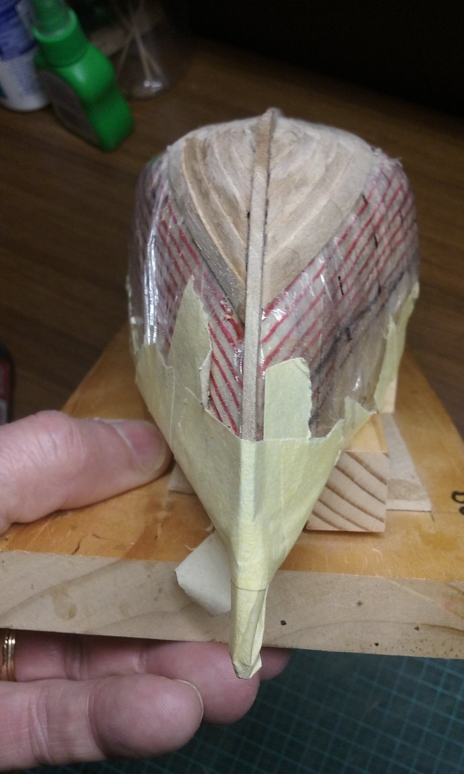
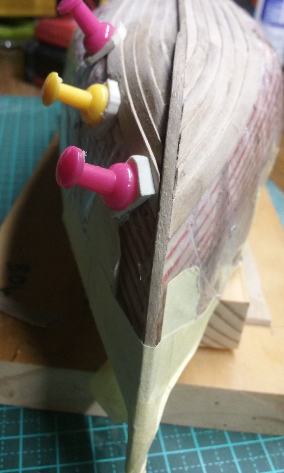
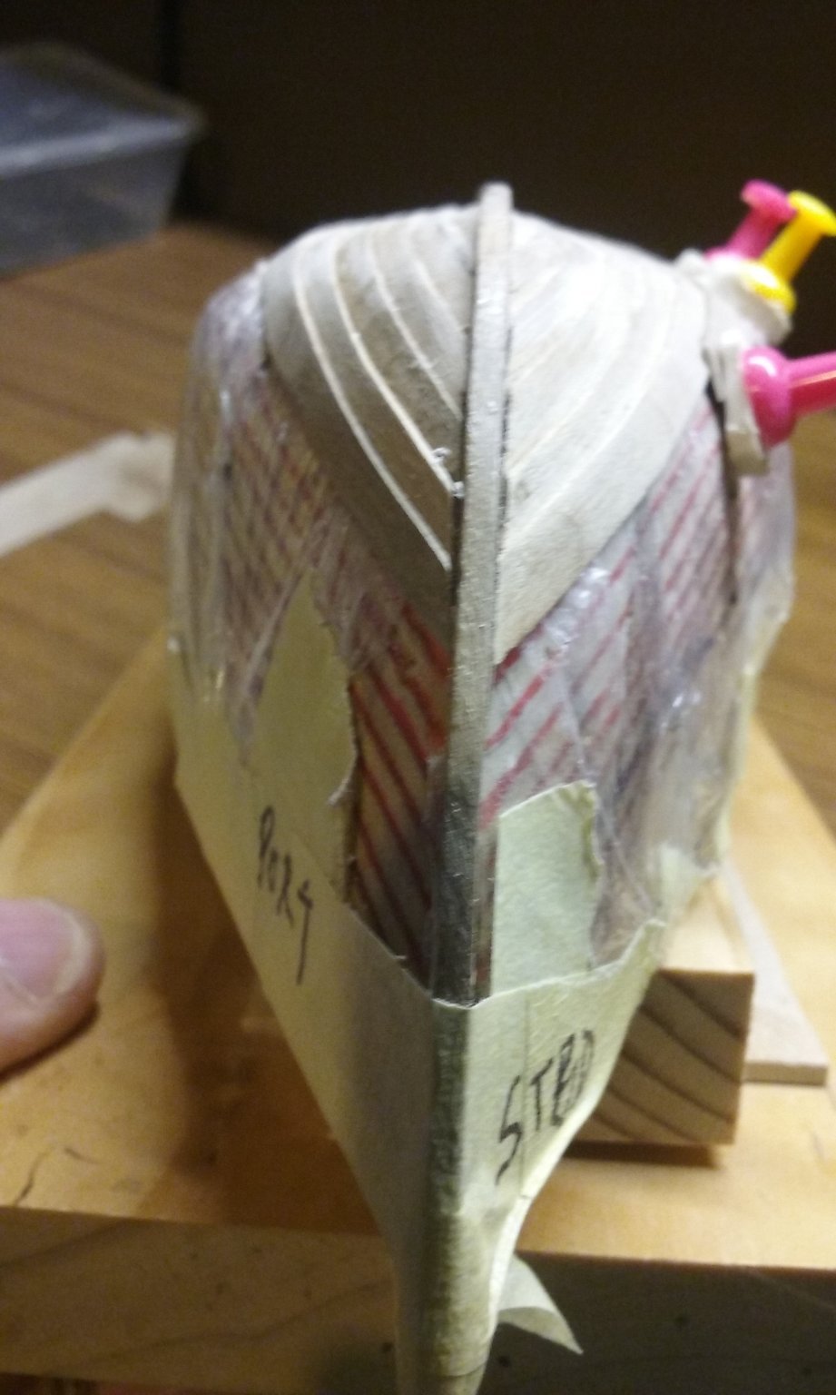
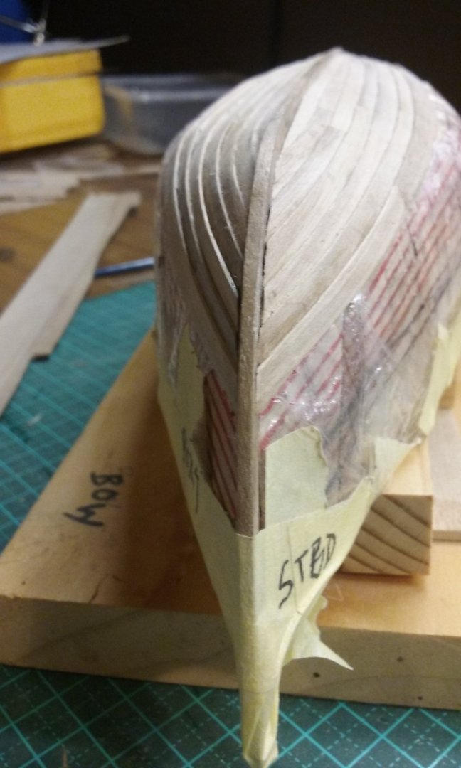
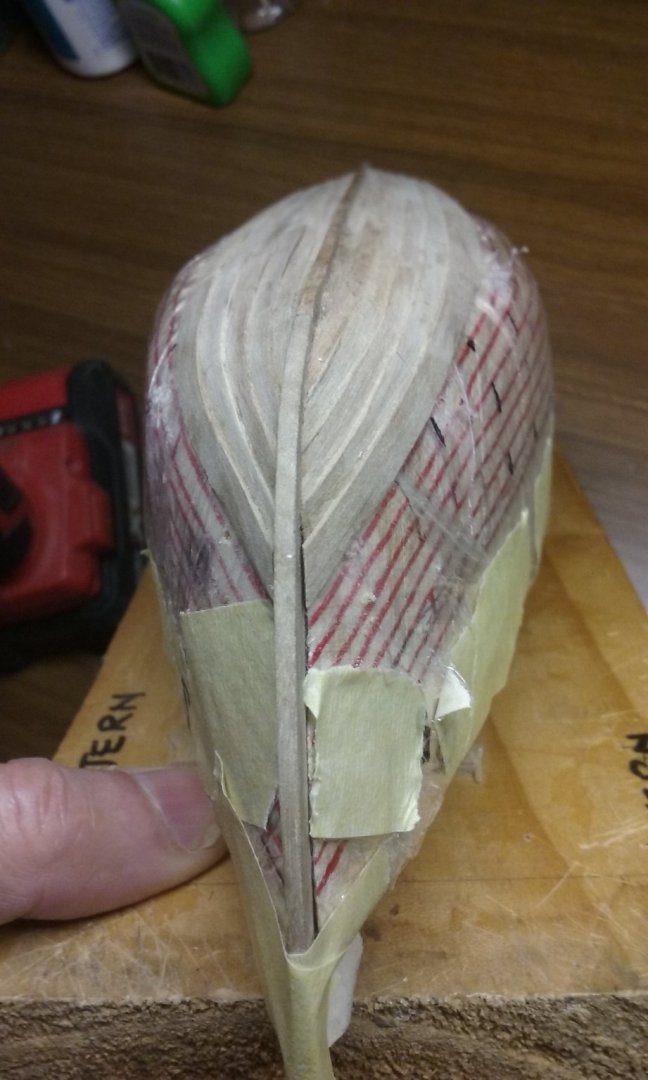
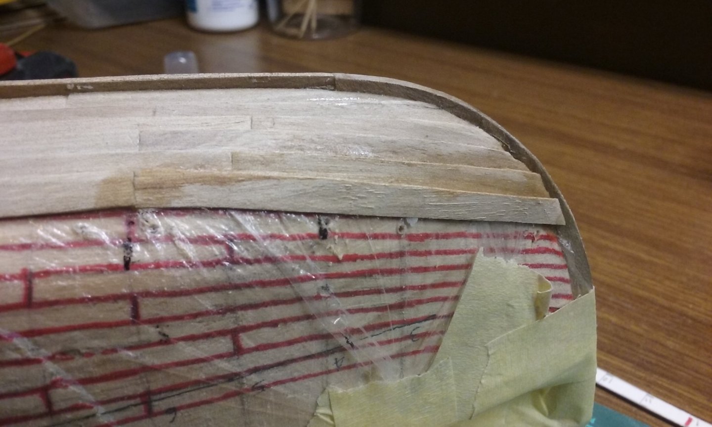
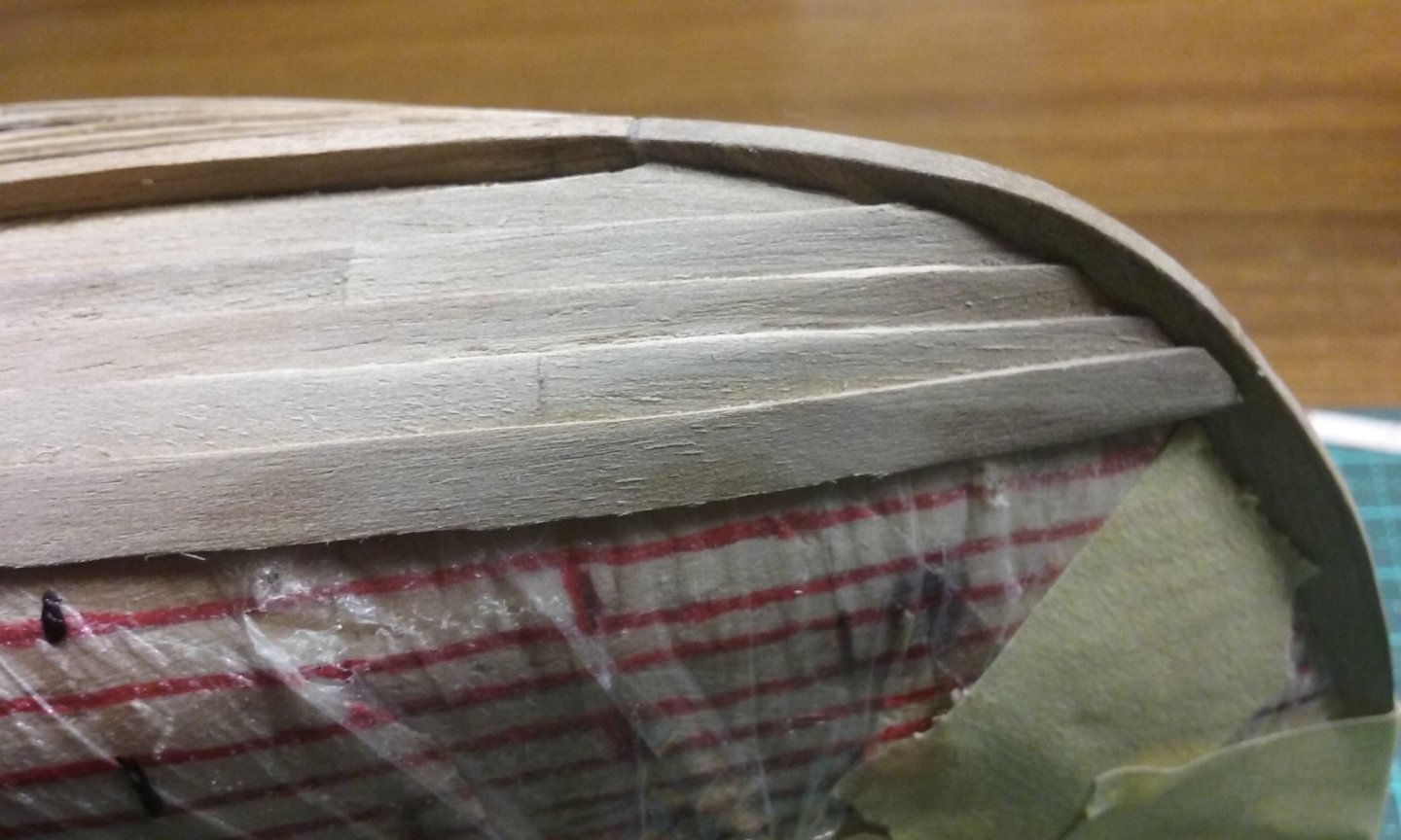
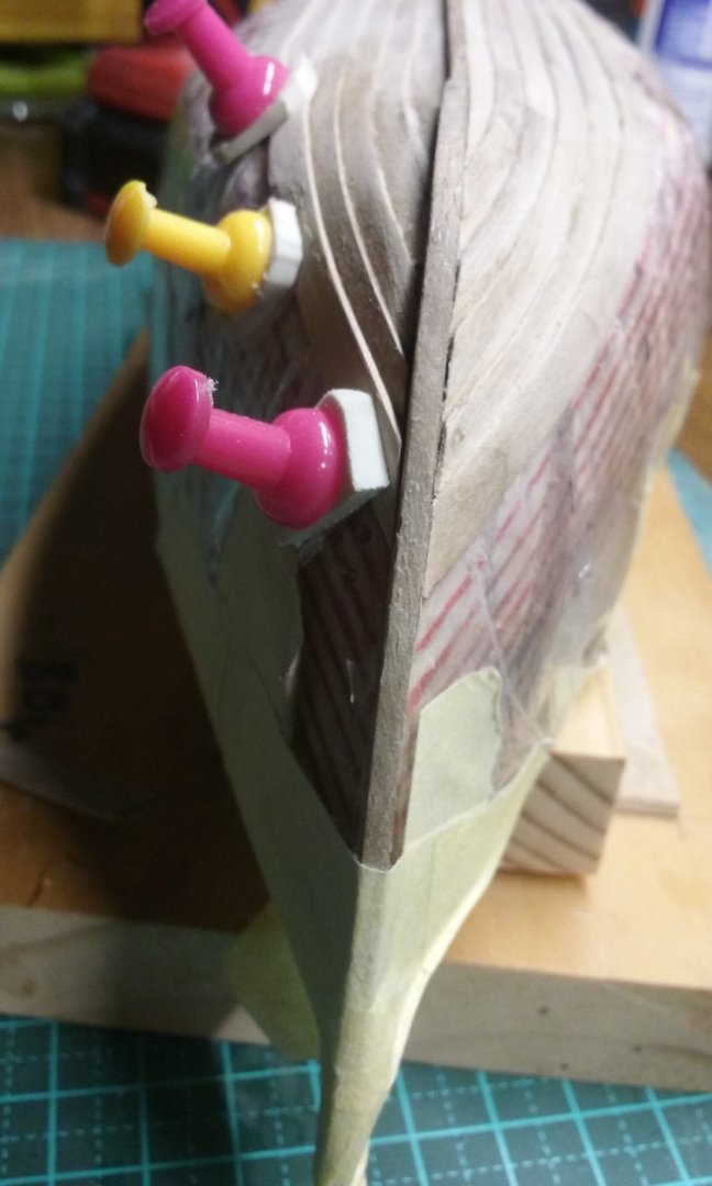
I suddenly realised the planks at the bow didn't line up properly from port to starboard. The planks for the stern were ok (apart from a bit of a problem with them merging with the sternpost - which I'll get to later). It's the stempost (i.e. at the bow) where the planks were wrongly placed - the starboard and port planks didn't line up with each other (my bad - I should have checked before I got to gluing): This what the planks at the bow look like: And here is the planking at the stern - you can see the difference. I took the outer two planks off and glued the first one back in a better place. But this brought up another problem - never having done clinker planking before, I had considerable difficulty getting the ends of the planks to sit properly at the stem and sternpost. In fact with these planks I was removing I'd ended up bodging the ends - to the degree that I decided - "They're already stuffed - I might as well just make new ones". So I did. All three. I'm getting better at doing the plank ends - the last couple look ok - but you can see the difficulty with the earlier ones. I'll have to go back to them and fix them later - perhaps by gluing slivers of wood in the gaps and trimming them down to shape. And here are the bow planks lined up properly. Having sorted out this hiccup I've done some more planking, but I haven't taken any photos yet. So you'll just have to wait. Steven


- 327 replies
-
- 12
-
-
I agree - it does look like it needs something to make it stand out. I think this vessel dates from before they had cast-bronze rams, but maybe a different colour or something would make the ram stand out more? Good idea - if you do a google image search for Ancient Greek shields you'll be able to find a lot of examples. Not sure how reliable they are, but steer away from the Greek Letter "Lambda" - that was specific to Sparta only. As far as spears go, the pic below should give some idea of dimensions and length. This ship is from considerably before the enormous 4.0 to 6.5 metre Macedonian sarissas. Steven
-
Welcome to MSW, Mart. Make sure you start a build log. Good to have you aboard. Steven
-
Oh, I quite agree. In fact a lack of caulking would make a pitch coating much more necessary. The representations of ancient Greek vessels are usually on red/black pottery, so colours are probably not reliable, but Byzantine ships (which are much more up my alley) are almost always shown black, as are many Western European mediaeval ships. Steven
- 62 replies
-
- 3
-
-
- amati
- greek bireme
- (and 1 more)
-
Hi Chuck and welcome to MSW! Do you have a ship in mind yet? Steven
-
HMCSS Victoria 1855 by BANYAN - 1:72
Louie da fly replied to BANYAN's topic in - Build logs for subjects built 1851 - 1900
If you google "glass spider" you get pictures of David Bowie. From Wikipedia - "The Glass Spider Tour was a 1987 worldwide concert tour by English musician David Bowie, launched in support of his album Never Let Me Down. " Steven- 1,013 replies
-
- 3
-

-
-
- gun dispatch vessel
- victoria
- (and 2 more)
-
The ancient Greek method of construction used a large number of tenons set into mortices in the edges of the planks to join them together (from https://en.wikipedia.org/wiki/Phoenician_joints ) I doubt that that would have left enough room for caulking. The Byzantines certainly caulked their ships - there are several references to it in contemporary records (there was even an Emperor named Michael the Caulker, because that's what he'd been before the Empress adopted him) but that was many centuries later and ship construction techniques had changed enormously. Steven
- 62 replies
-
- 5
-
-
- amati
- greek bireme
- (and 1 more)
-
HMCSS Victoria 1855 by BANYAN - 1:72
Louie da fly replied to BANYAN's topic in - Build logs for subjects built 1851 - 1900
Looks amazing as usual, Pat. I can't see the error, but then I don't know what a spider band is. Is it like a glass spider? Sorry, being silly . . . Steven- 1,013 replies
-
- 6
-
-
-
- gun dispatch vessel
- victoria
- (and 2 more)
-
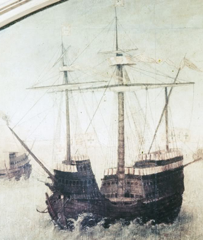
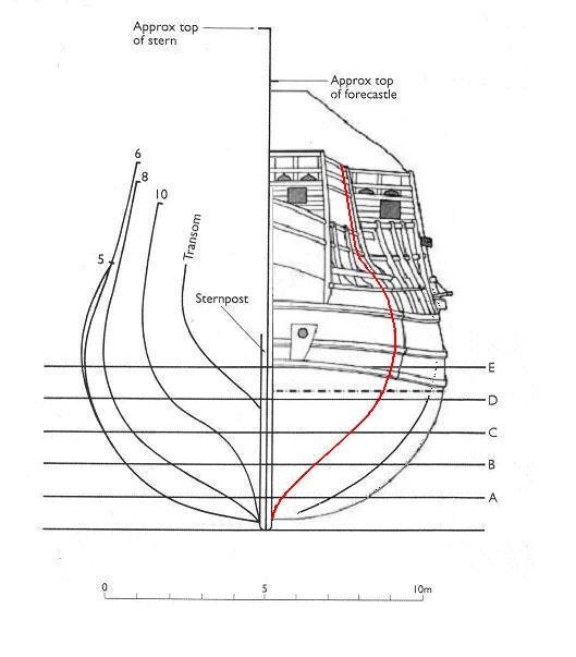
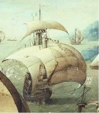
Honestly, I don't think this would be necessary. Though we have to make allowances for artistic licence, contemporary illustrations do seem to show the planking rising at the bow. The reconstruction drawing of the Mary Rose shows a less extreme rise, but it has to be kept in mind that this part of the hull was never recovered, so the reconstruction may be based on later practice. And of course this also applies to the RMG model. Steven
- 50 replies
-
- 4
-
-
- mary rose
- caldercraft
- (and 1 more)