Louie da fly
-
Posts
7,990 -
Joined
-
Last visited
Content Type
Profiles
Forums
Gallery
Events
Everything posted by Louie da fly
-
 Very nice work as usual, Dick. Your builds are a pleasure to follow. I'd agree with that. The earliest representations I've seen of parrel trucks is early 15th century. Admittedly, artistic licence has to be taken into account (the artist just might not have included them in his picture) but the available evidence points to them coming in around about that time. Steven
- 186 replies
-
- 2
-

-
- keelless
- reverse clinker
- (and 4 more)
-
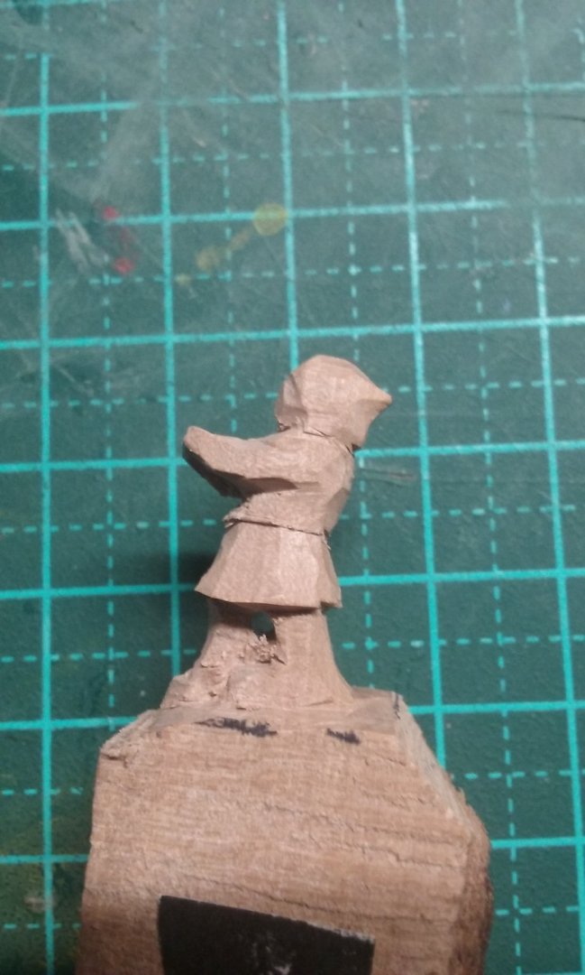
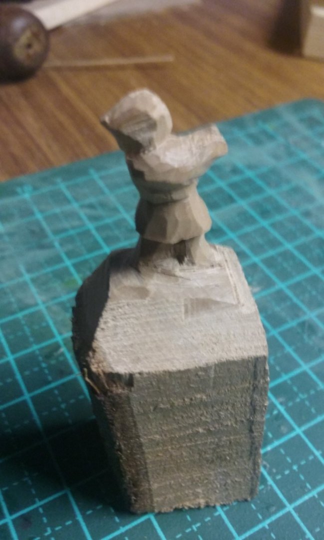
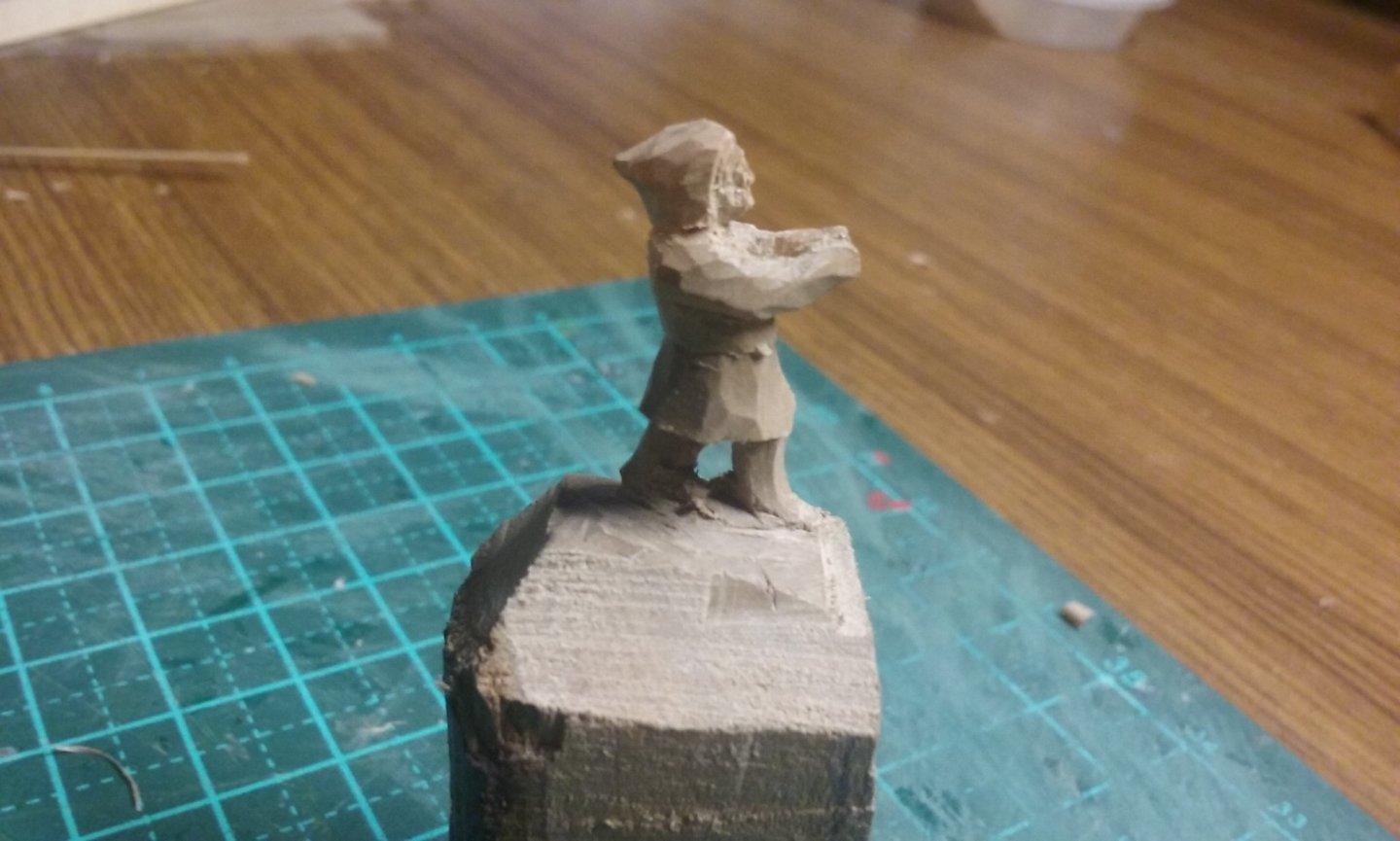
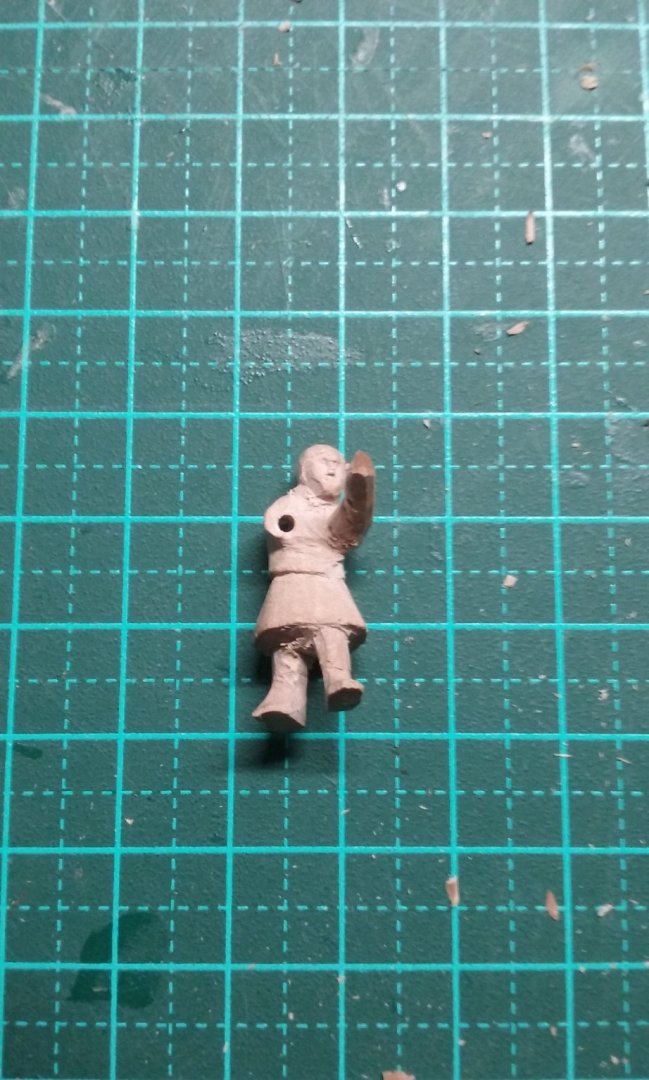
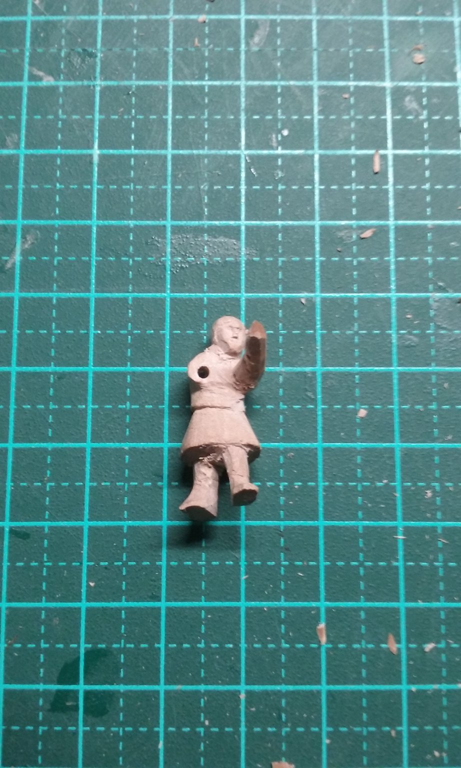
More work on the crewmen. Here's more progress on the second windlass-man. Note he's wearing a "hoodie". And beginning the first crewman hauling in the anchor. (I'm using the windlass man as a handle to hold the anchorman as I work on him. When both are complete I'll separate them.) Steven


.thumb.jpg.6e646bc8294ee0a955b463f3429953cc.jpg)


- 327 replies
-
- 13
-
-
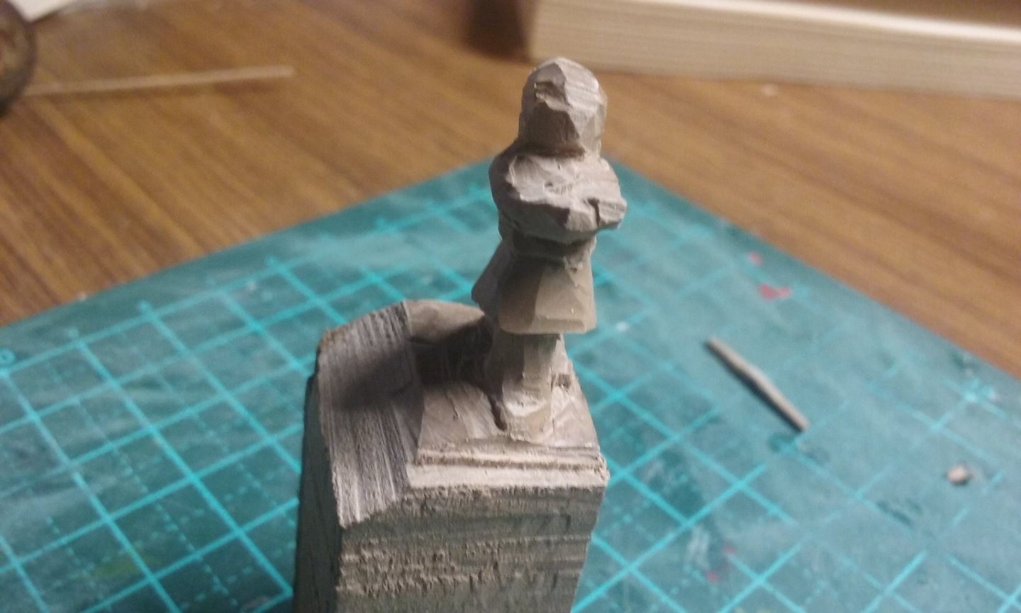
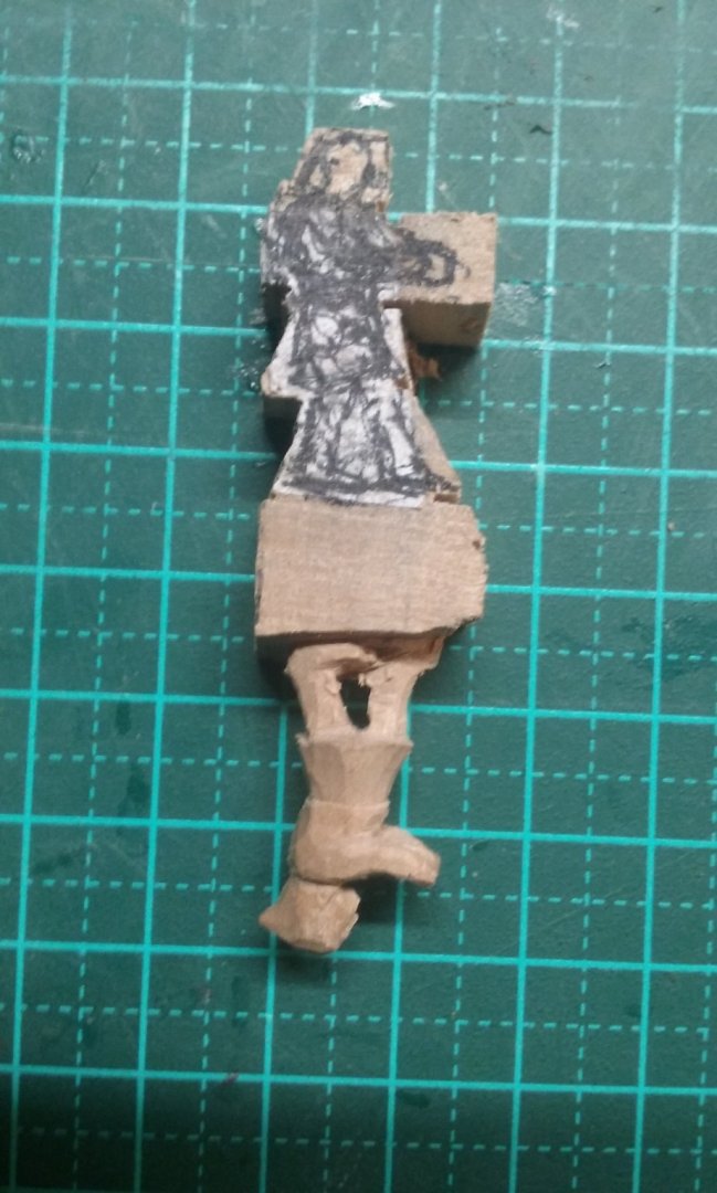
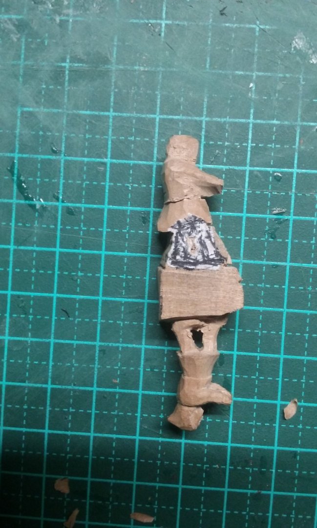
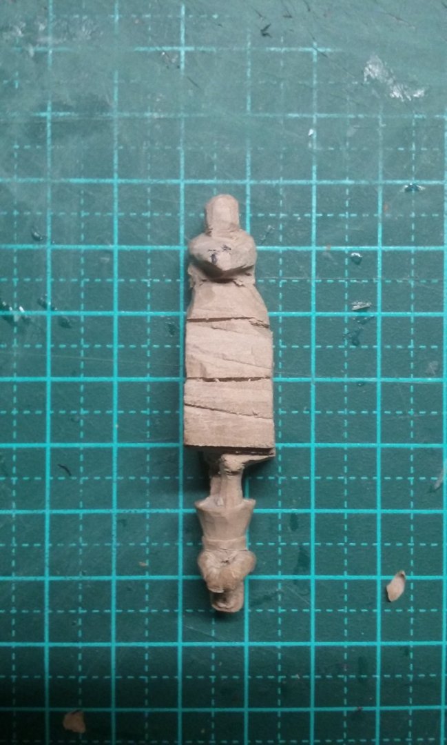
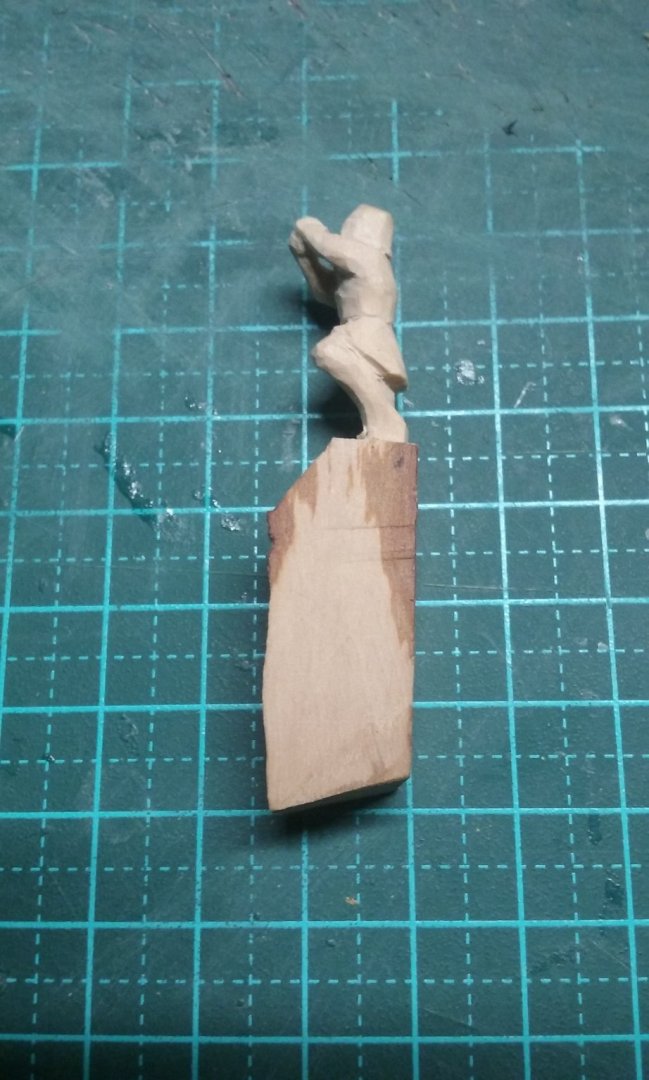
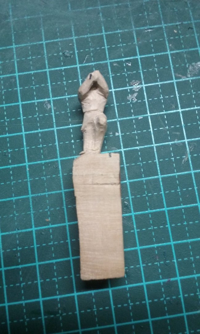
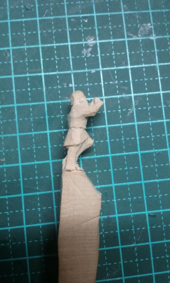
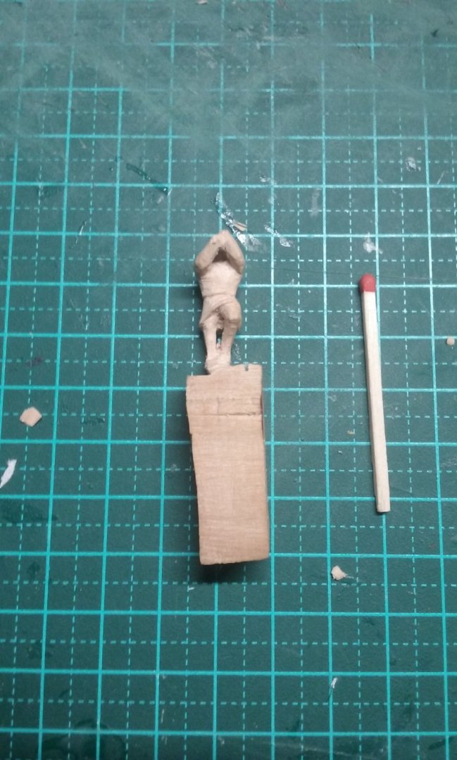
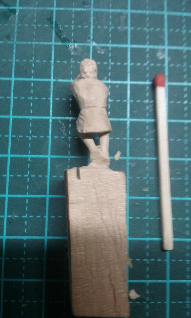
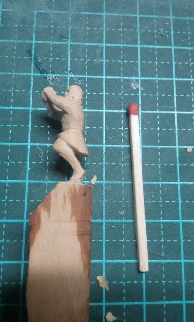
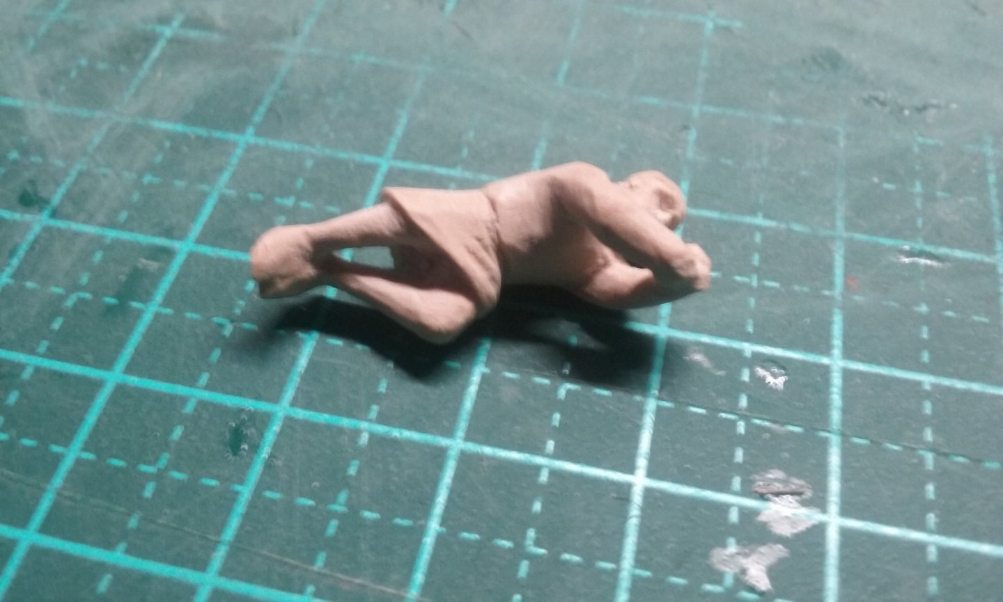
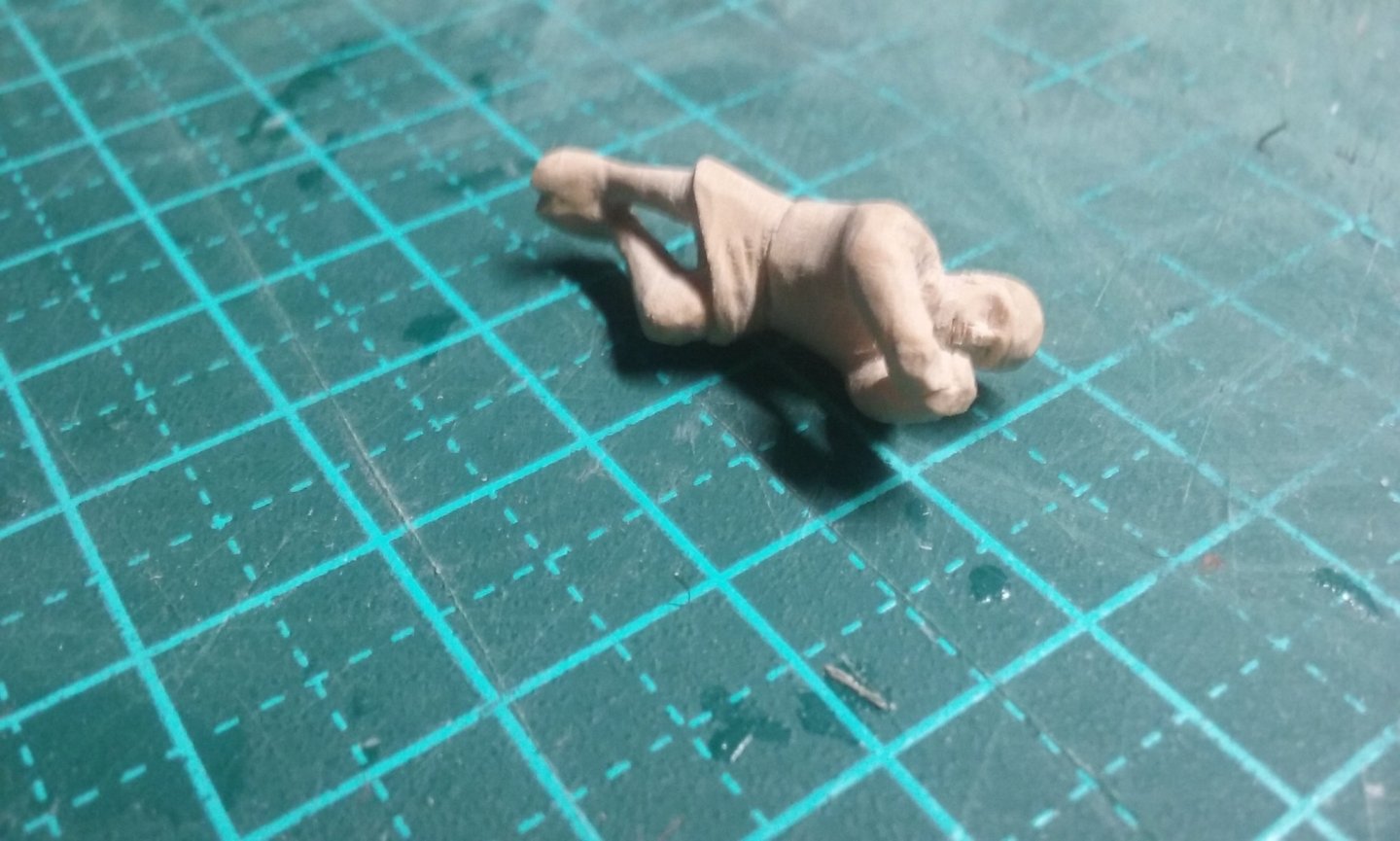
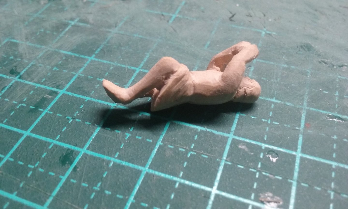
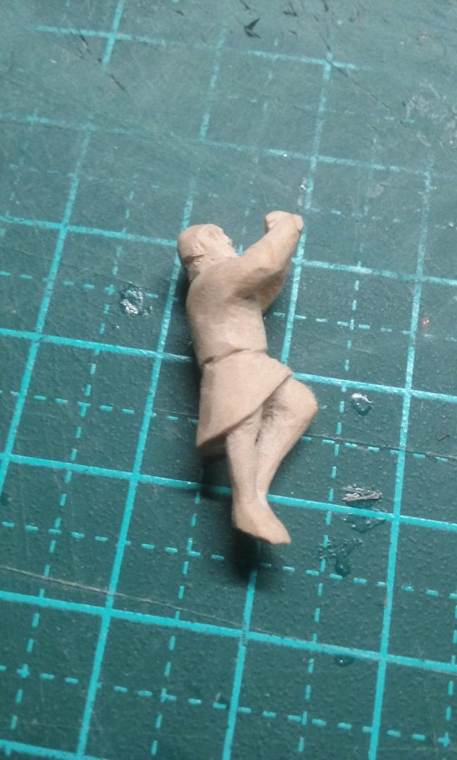
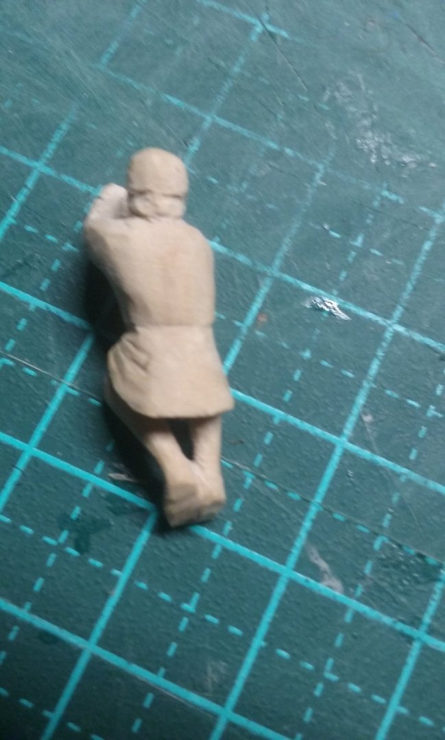
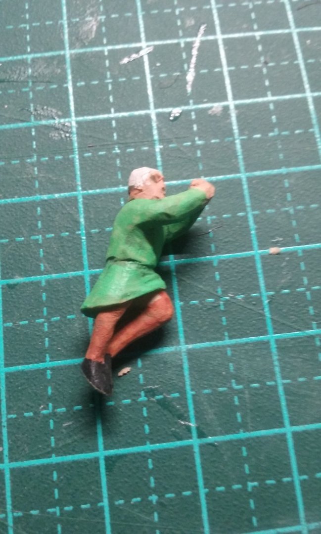
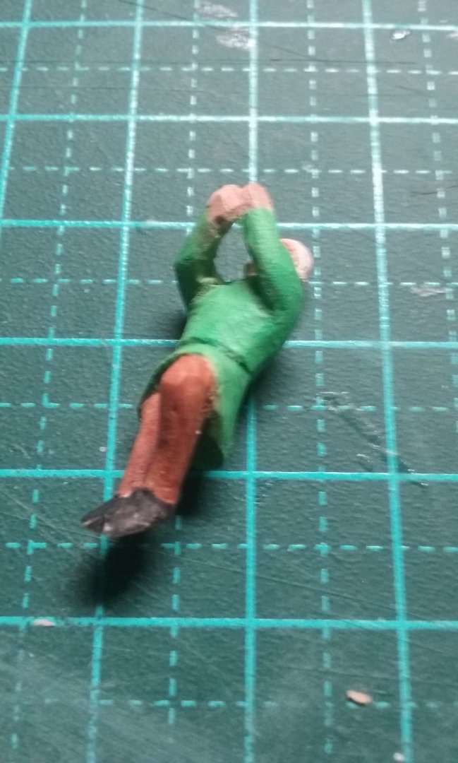
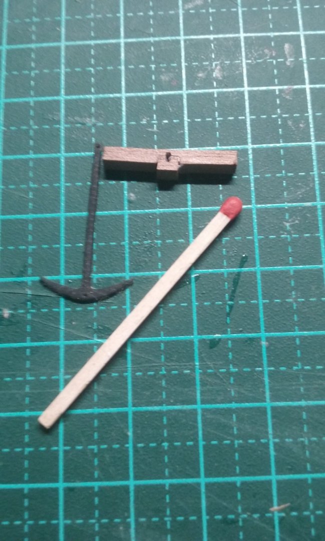
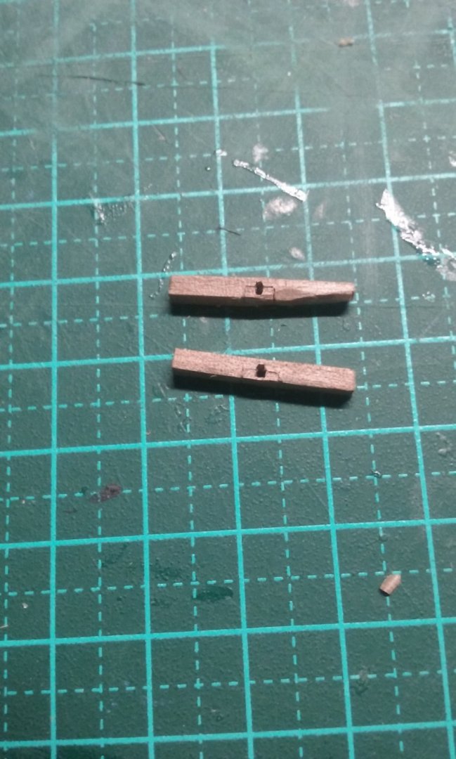
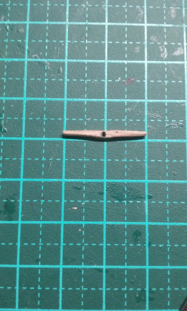
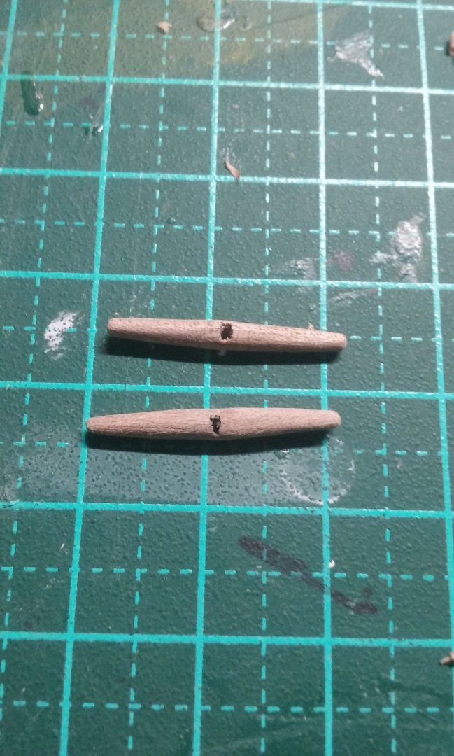
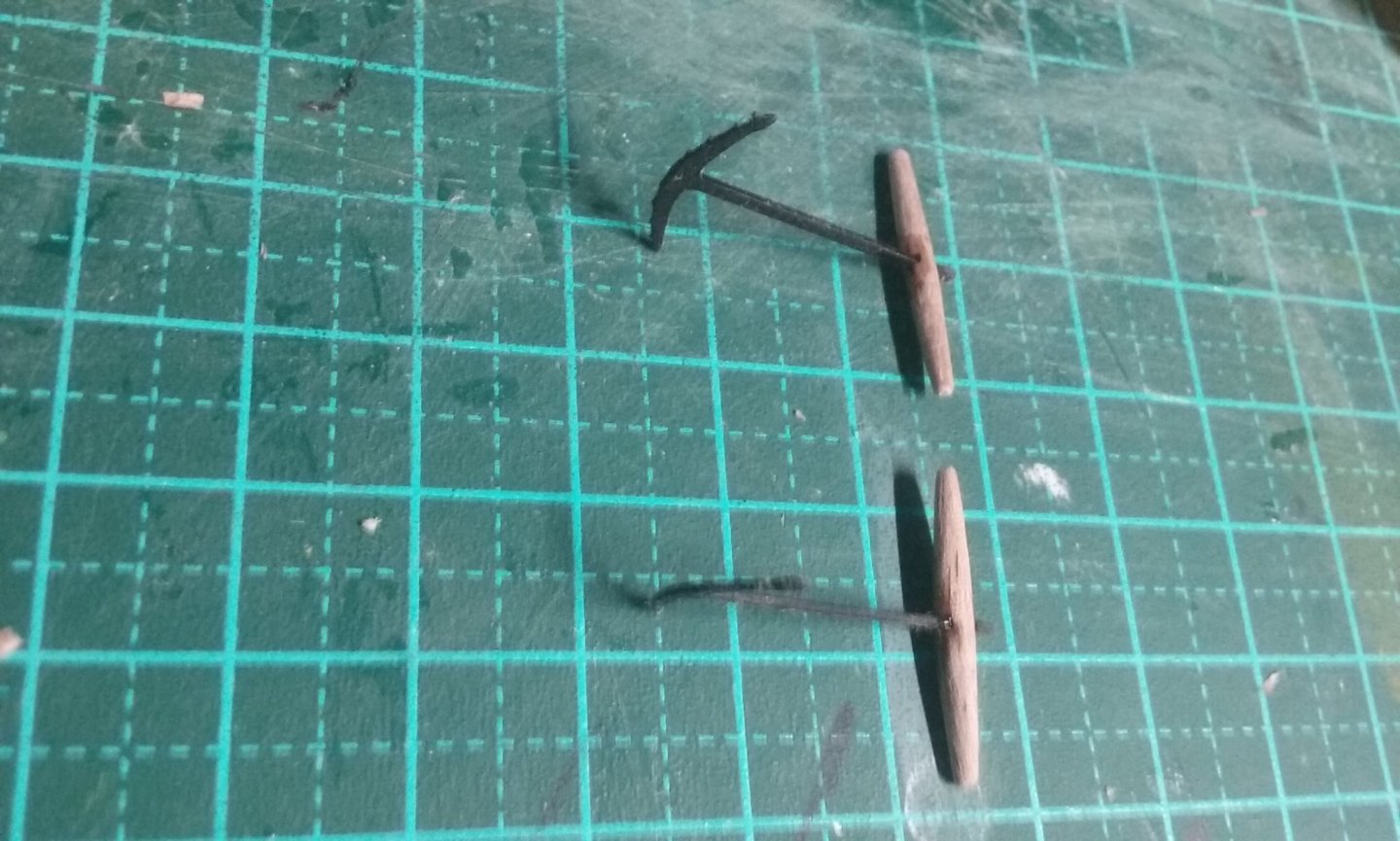
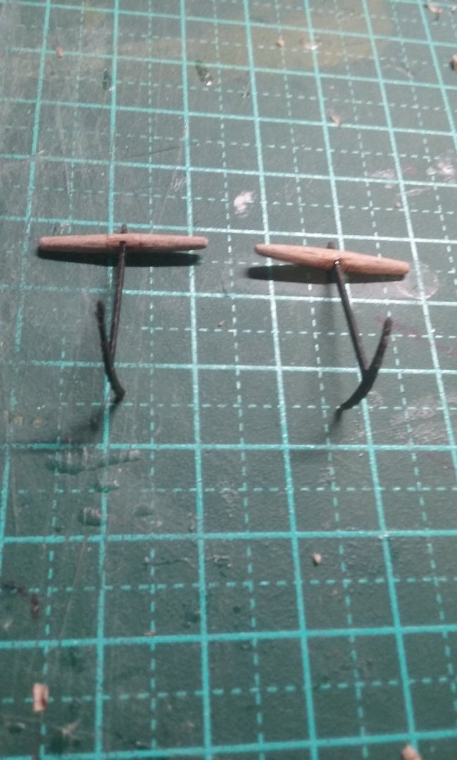
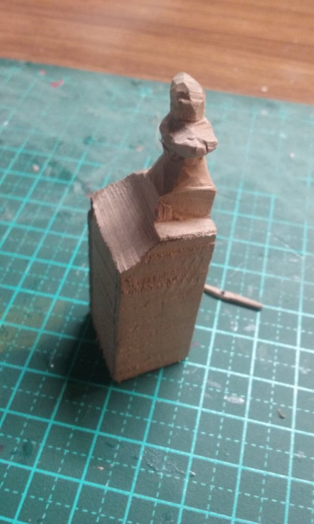
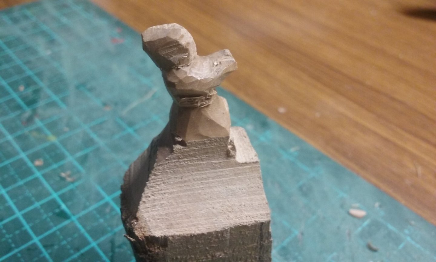
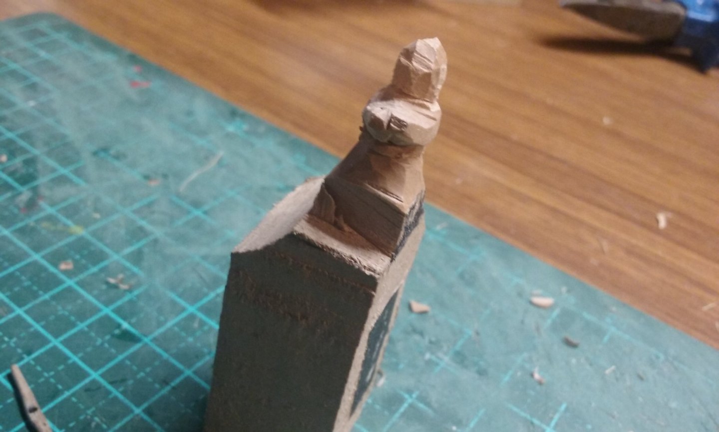
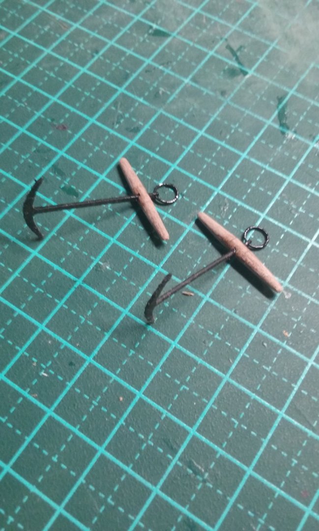
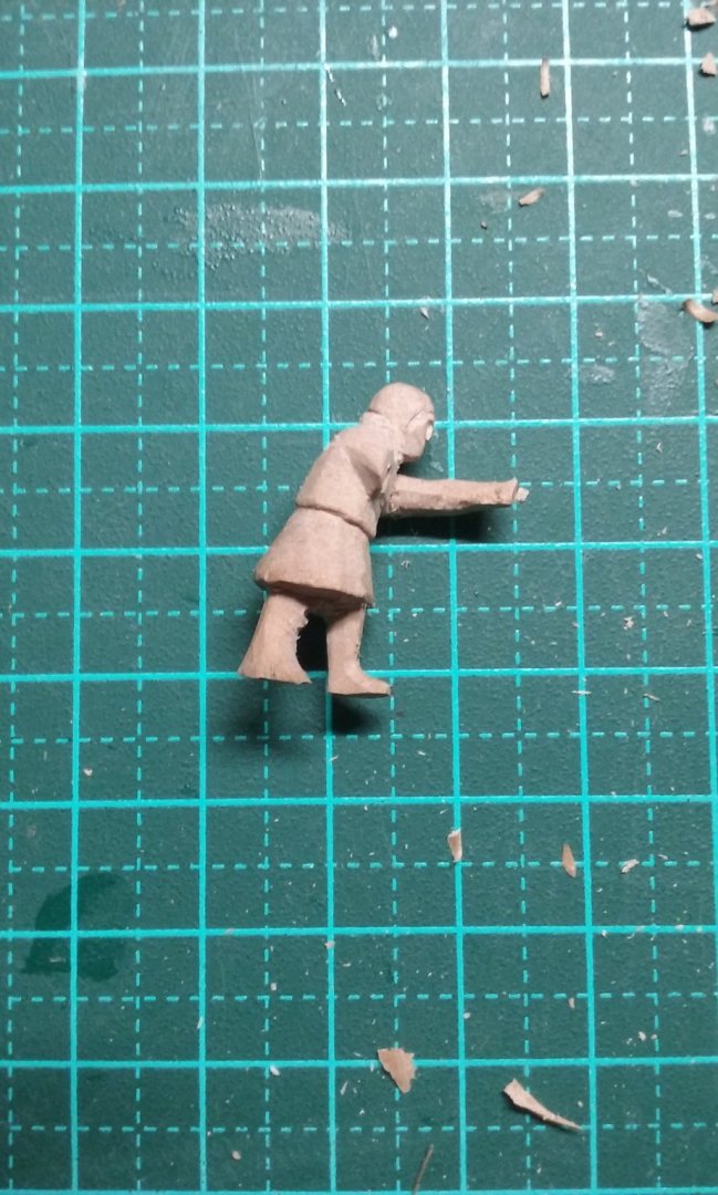
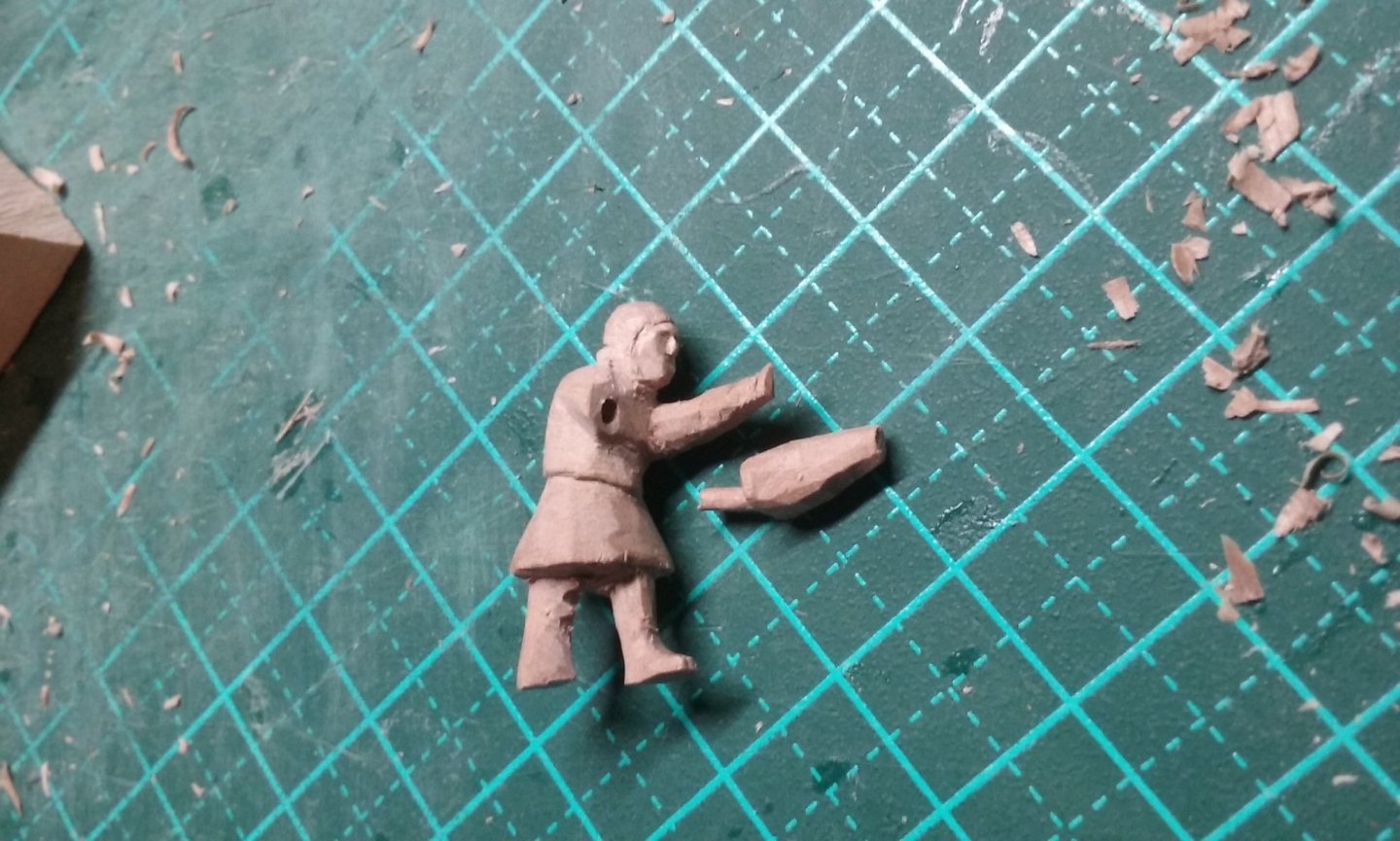
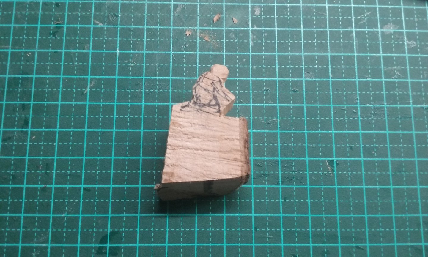
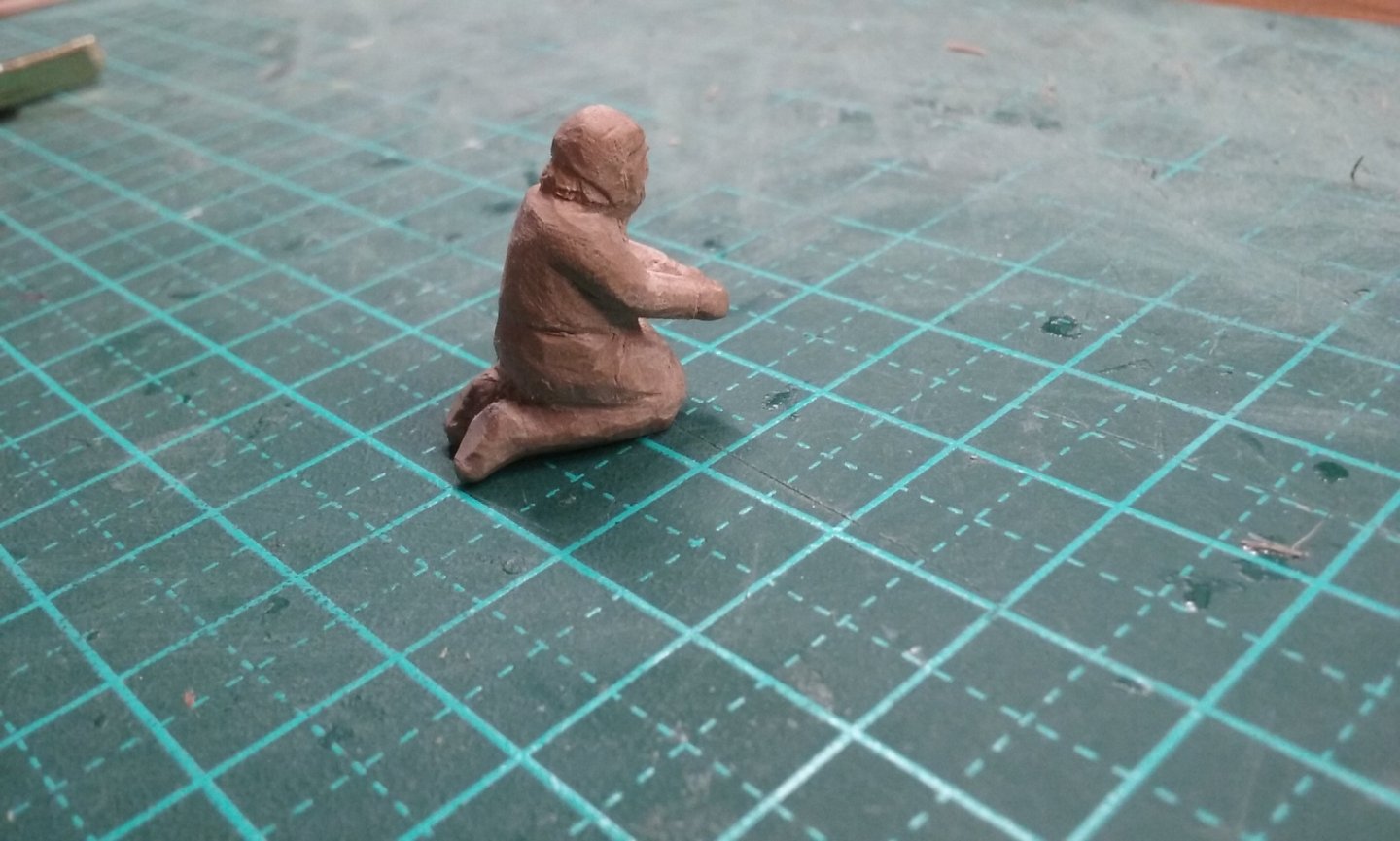
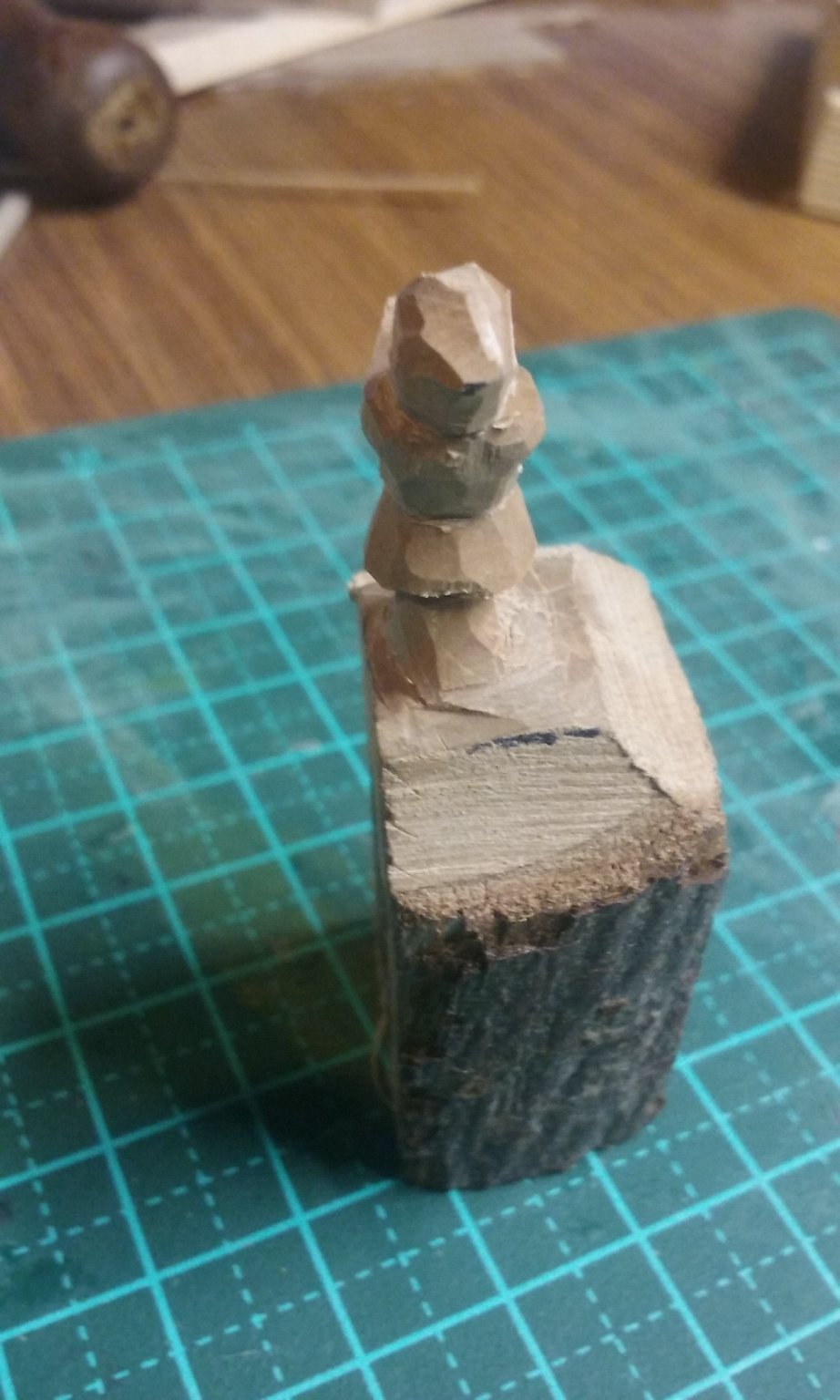
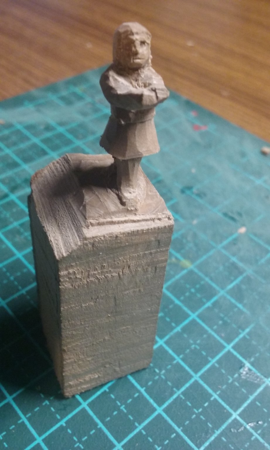
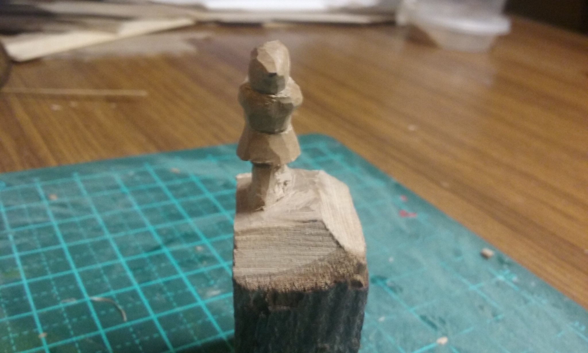
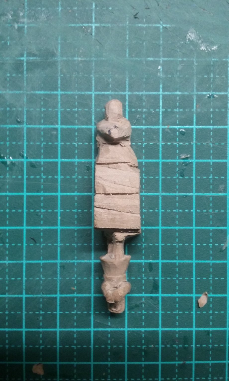
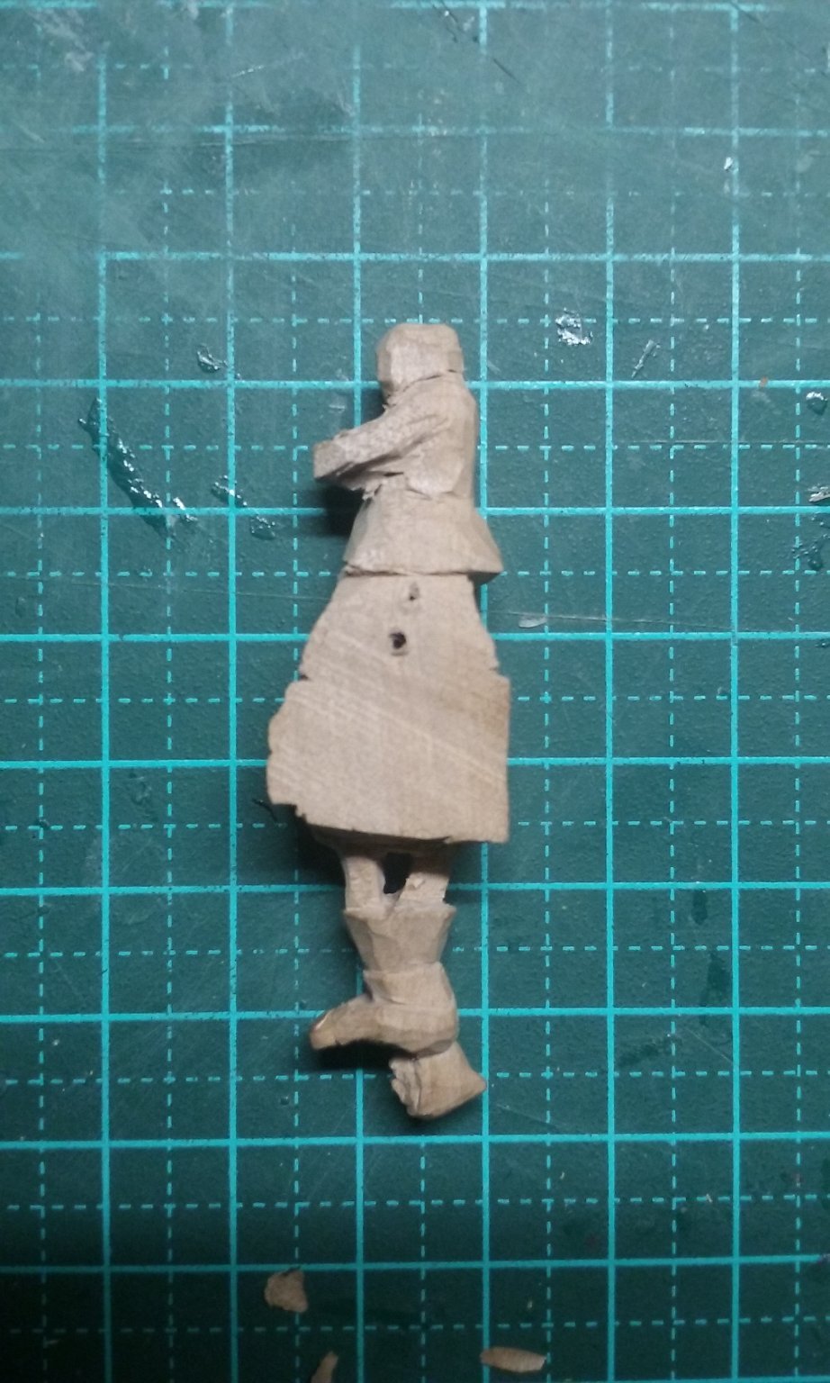
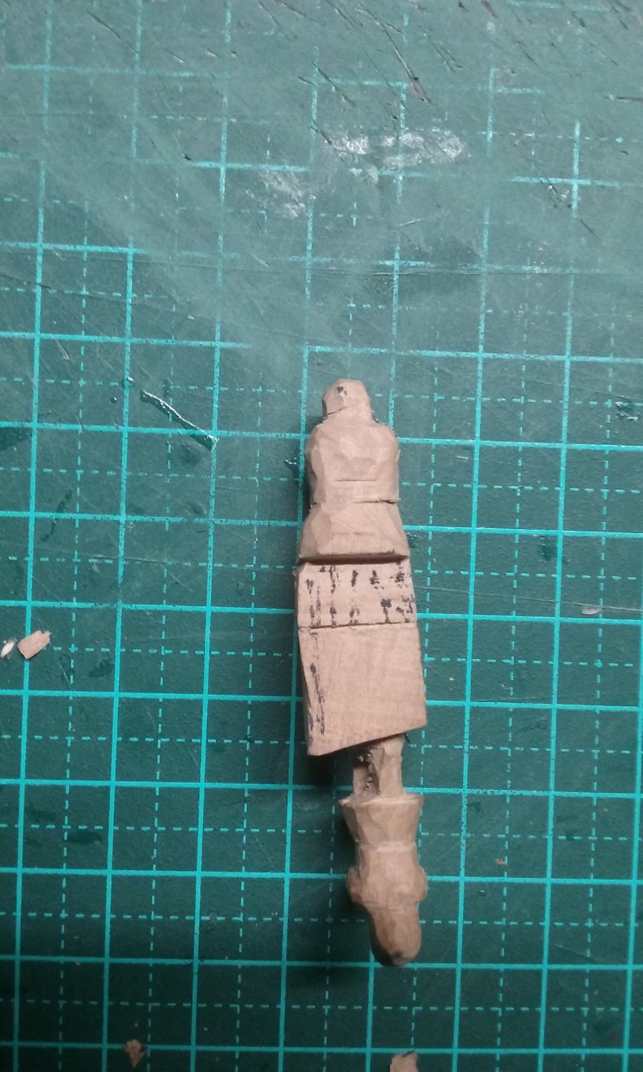
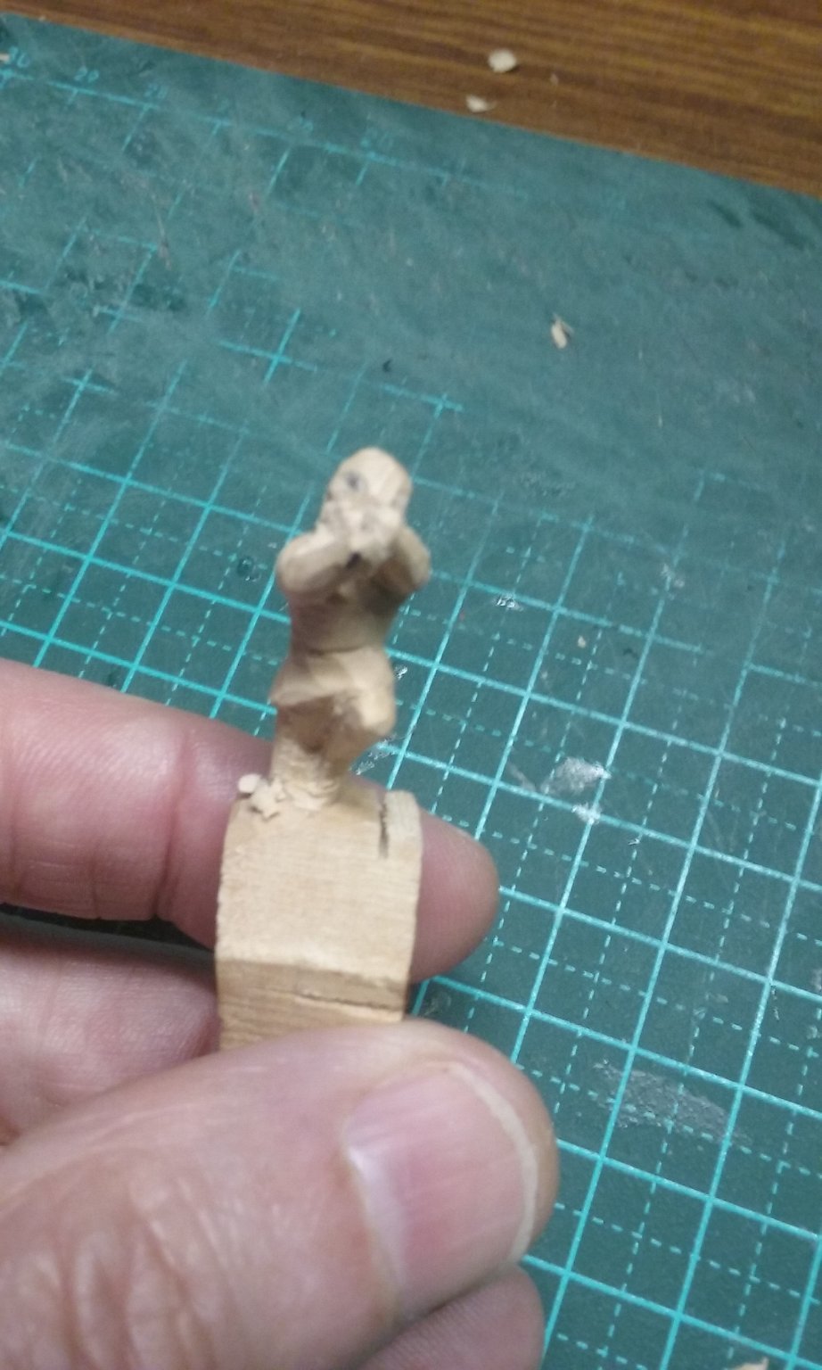
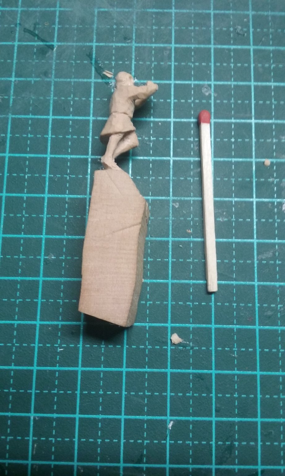
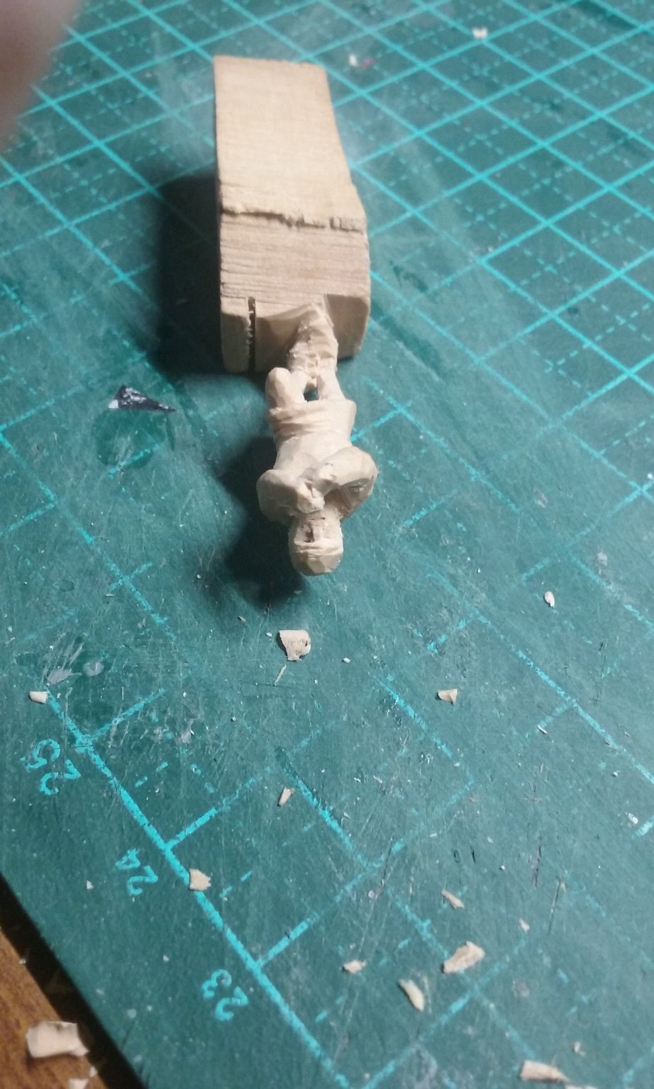
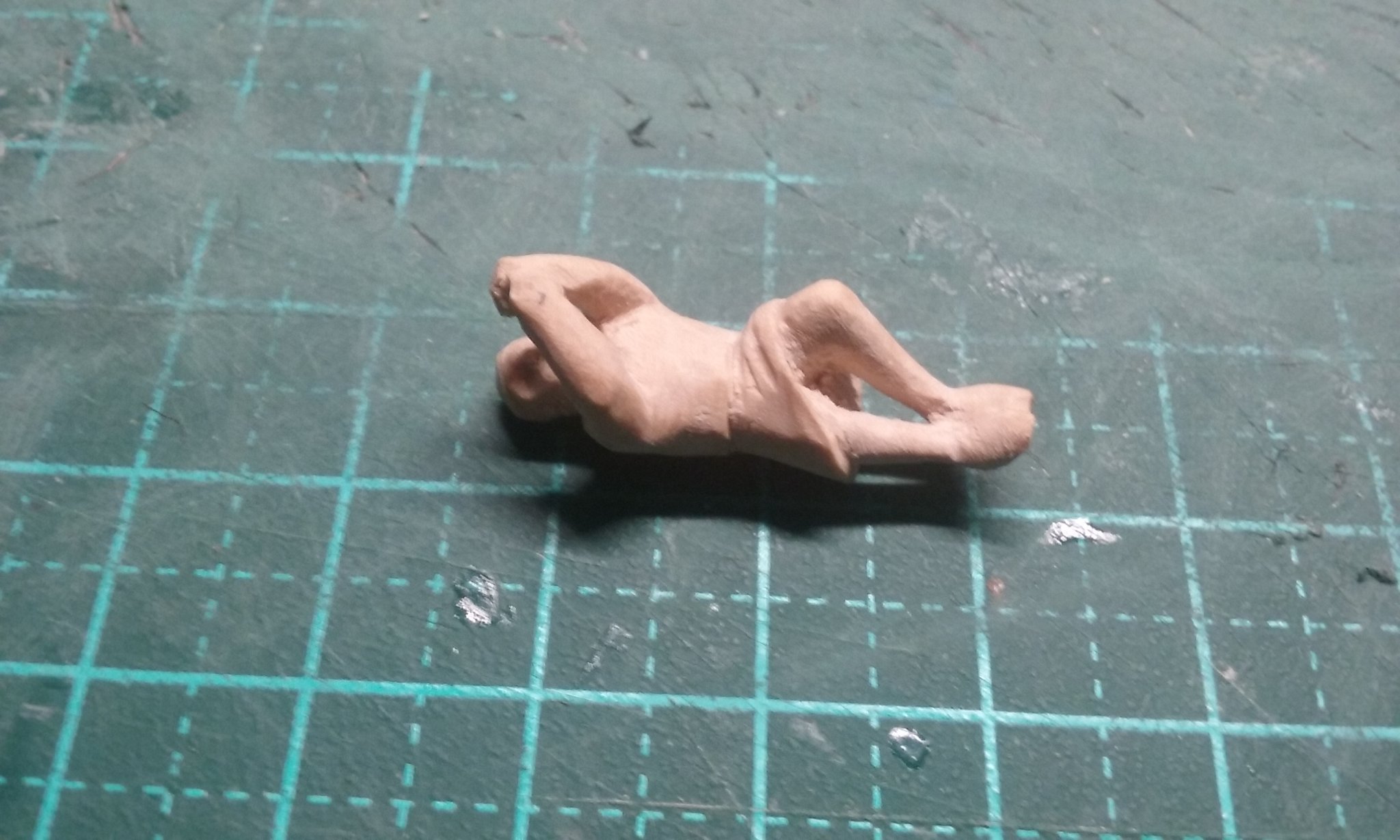
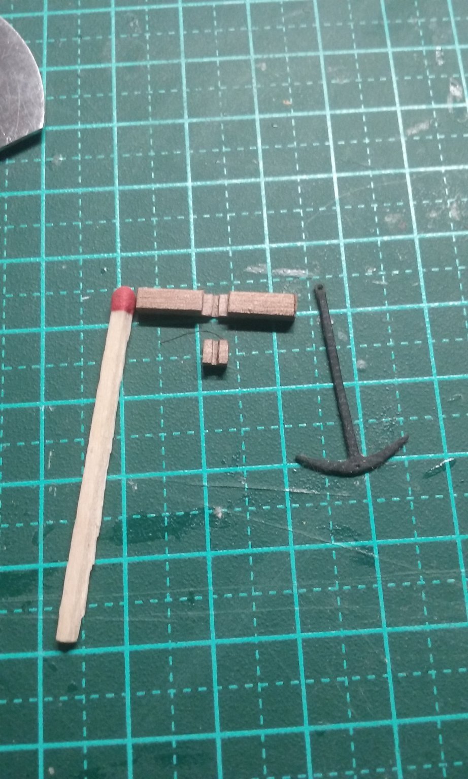
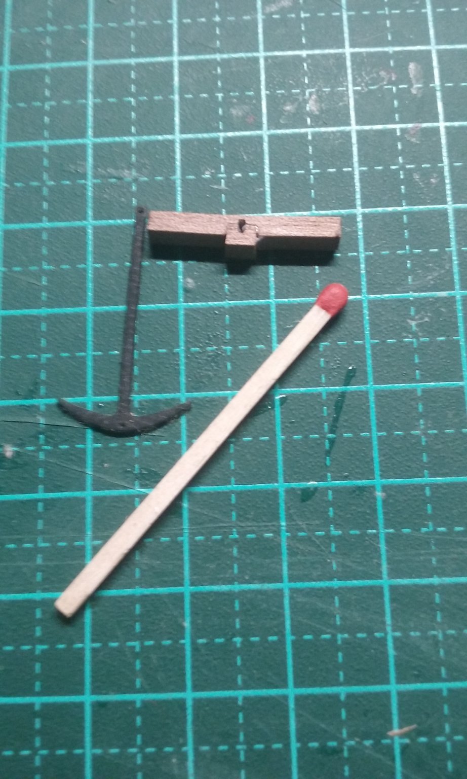
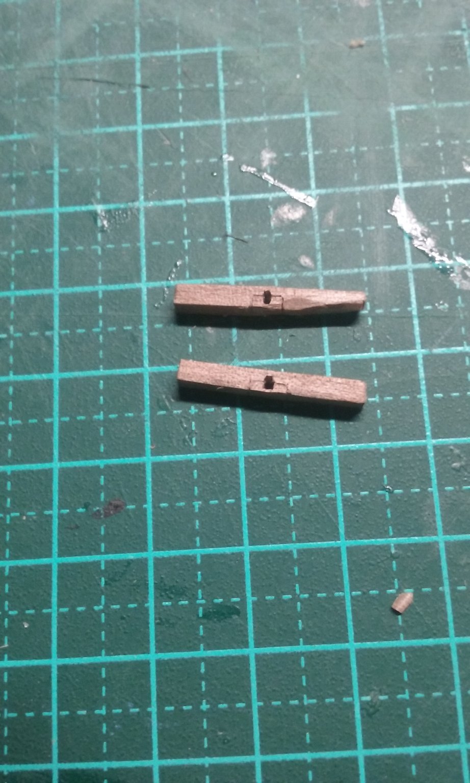
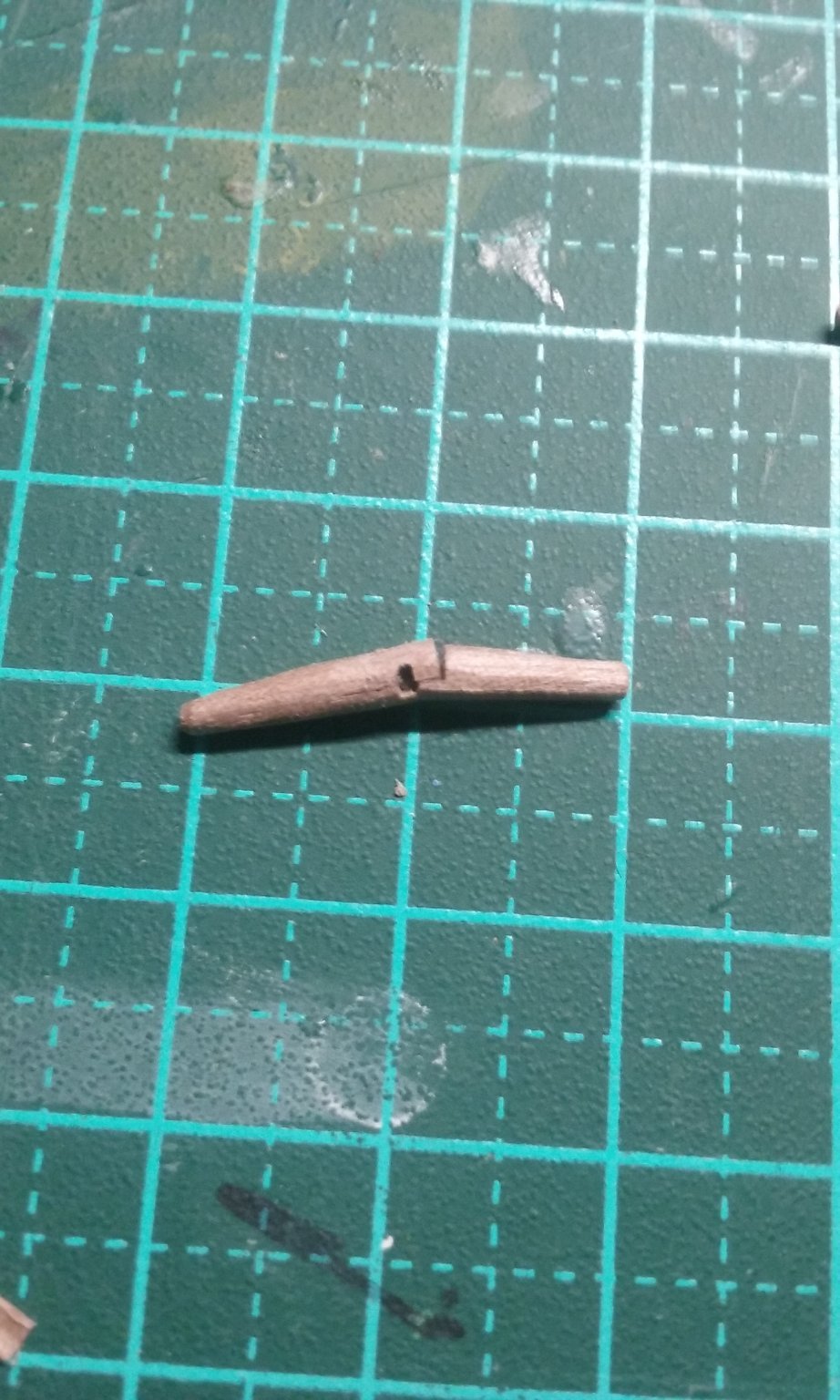
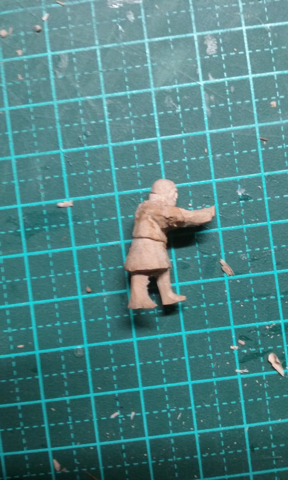
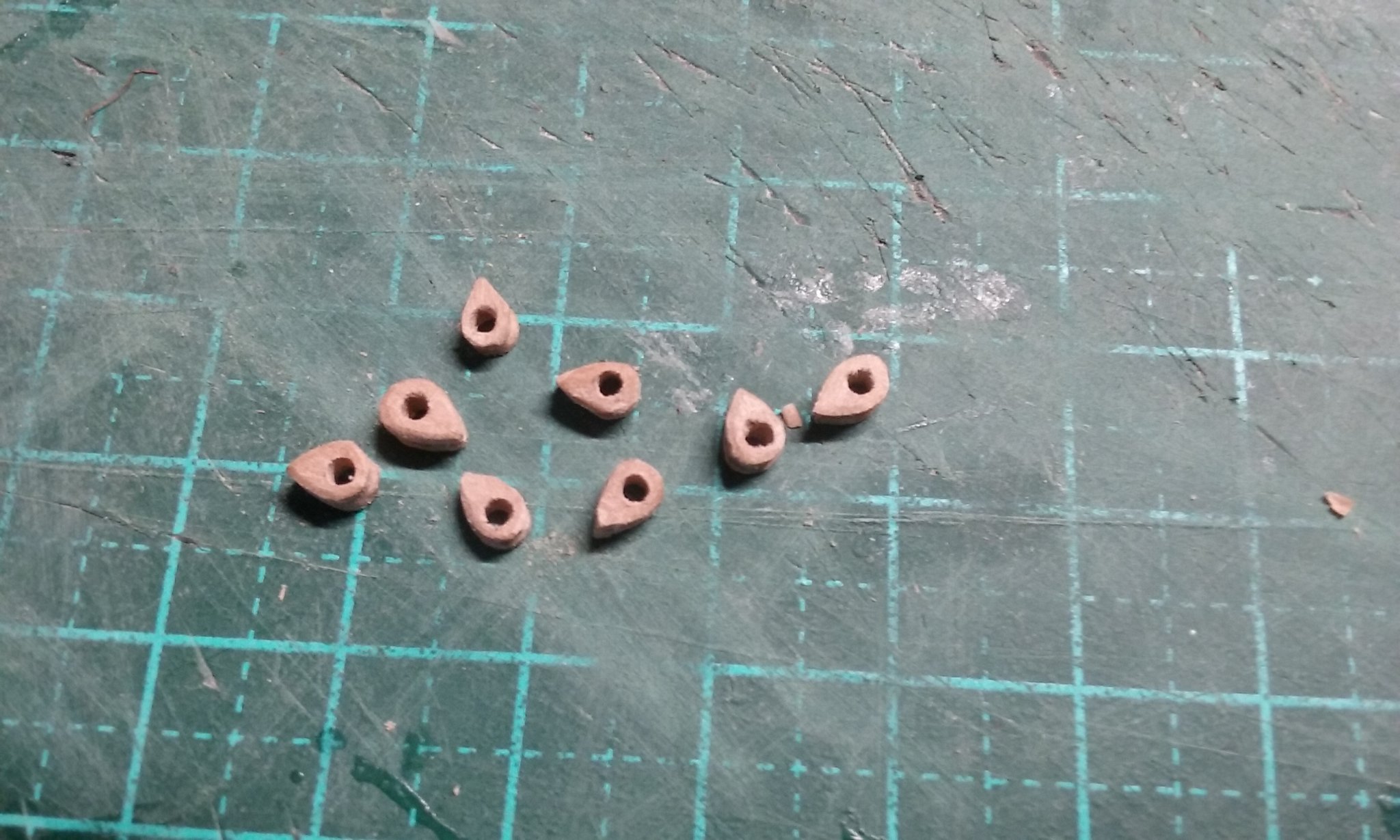
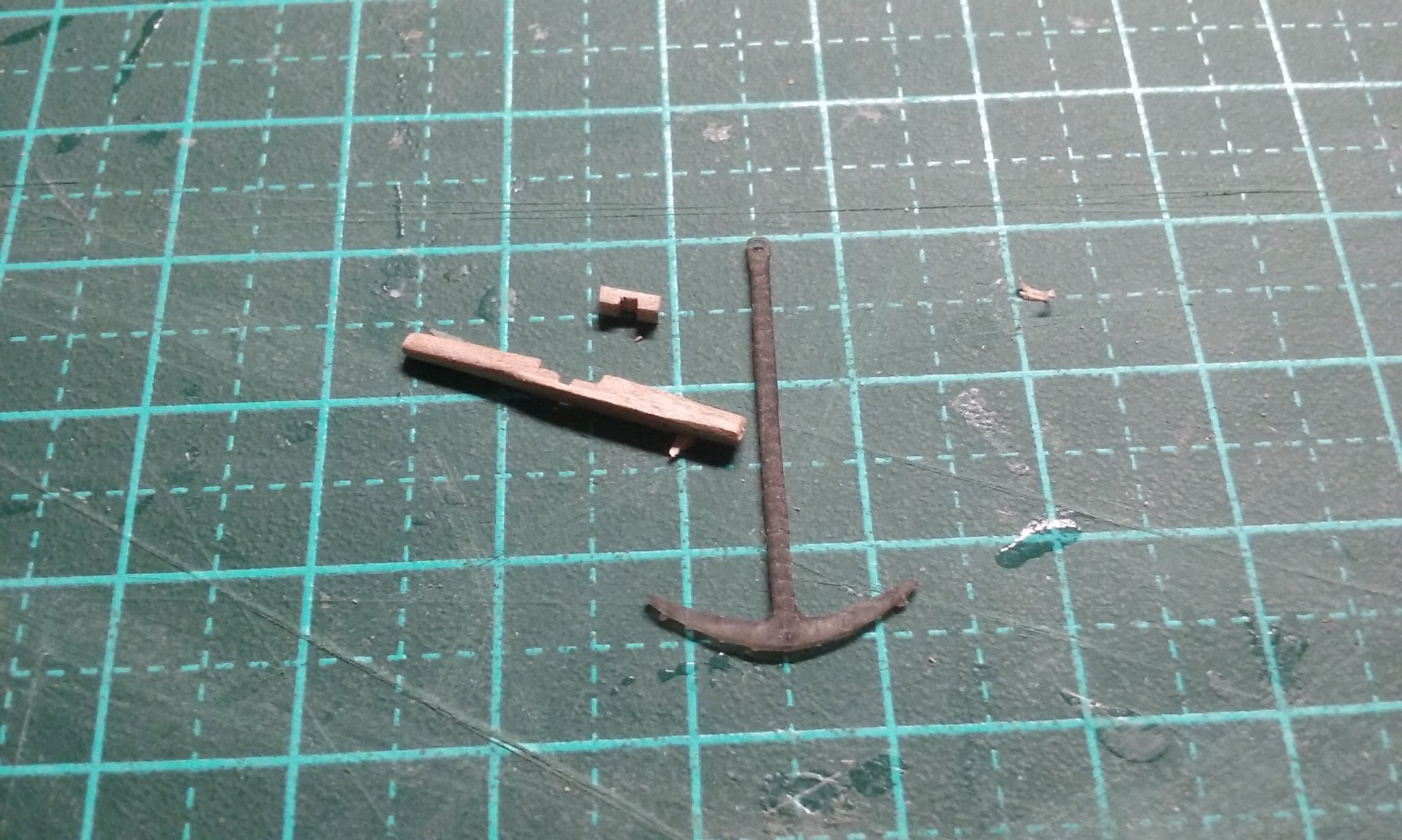
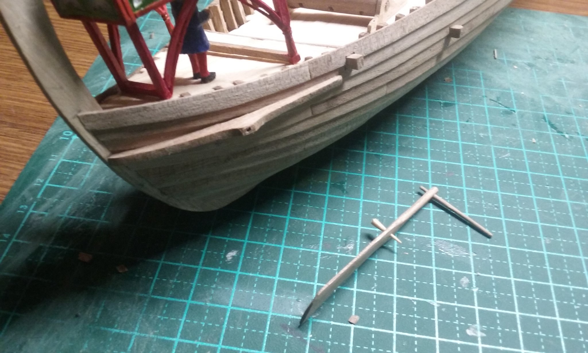
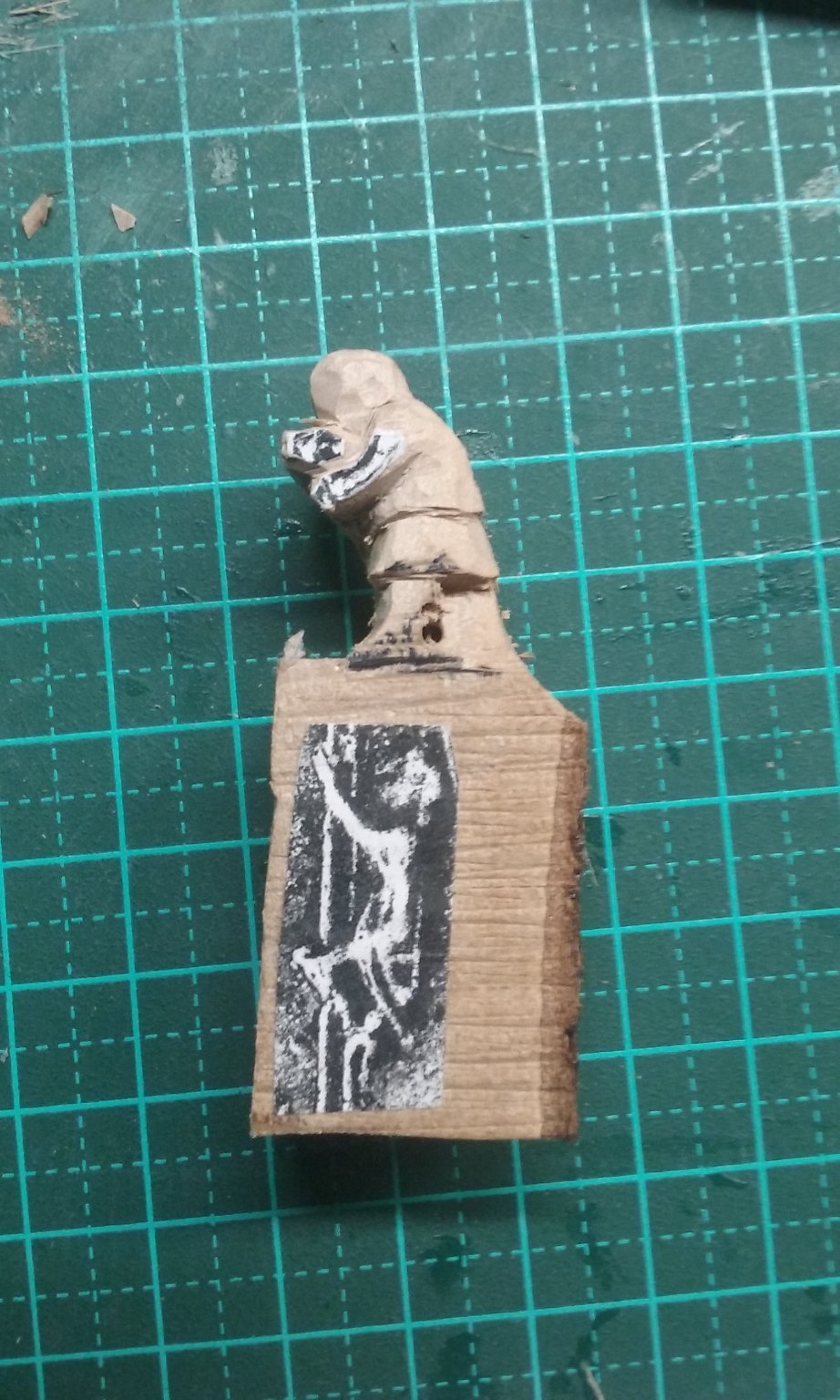
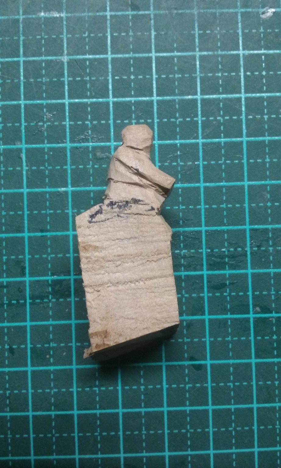
Thanks everybody for the likes and comments. Next is the crewman climbing a shroud to get to the yard and unfurl the sail. This is perhaps the most difficult figure I've ever had to carve - a very awkward shape, with the hands and feet all having to line up along the shroud. I'd been getting a bit short of pear wood, so I decided to try using some wood from an apricot tree that had been removed from the garden maybe a year or more ago. It's nicely seasoned and the grain turns out to be even better for carving than pear wood. And there's LOTS of it! And finally, painting. The anchor stock turned out to be too thin and I couldn't get it consistently shaped. So I started again with thicker bits of wood. The first "insert" was just cut to shape so it fitted beautifully, when it leapt out of my fingers and into another dimension. So I had to make another one. Surprisingly, and in flagrant violation of one of the fundamental Laws of the Universe, the missing piece didn't turn up as soon as the replacement was made. Curiouser and curiouser . . . Fortunately, no further mishaps of that sort. On the other hand there was a mishap of another sort . . . Fortunately, a bit of white glue and it was as good as new. Here are the completed stocks. Fitting the stocks to the anchors: And my thanks again to @henrythestaffy for 3d printing the anchors themselves [advertisement]. Making the rings: Rings fitted . . . and painted: And now the second crewman for the windlass. (After the previous problem, I made a plasticiene (modelling clay) figure as a "draft" to get his hands in the right place. I hope I get it right this time.) That's all for now. Steven


- 327 replies
-
- 16
-
-

-
What a beautiful model - and no, don't make oarsmen - I had enough trouble making 50 of them at 1:50 scale. Steven
-
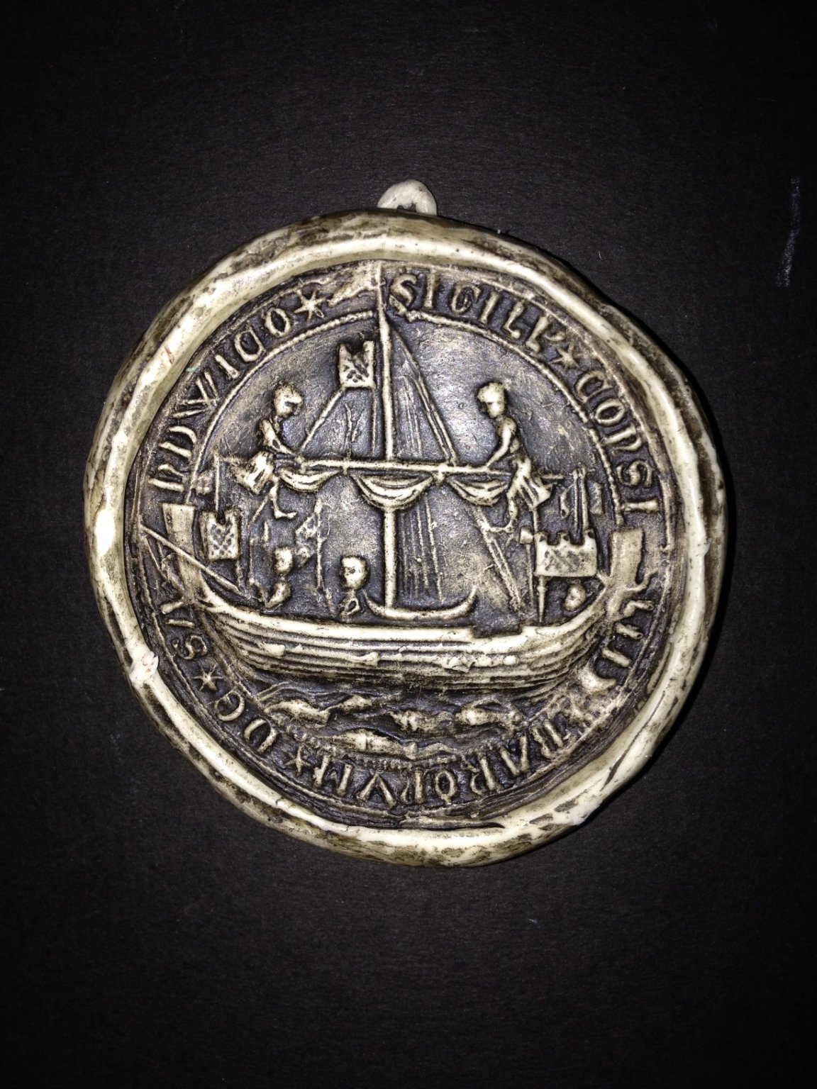
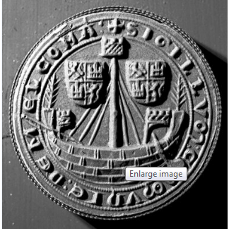
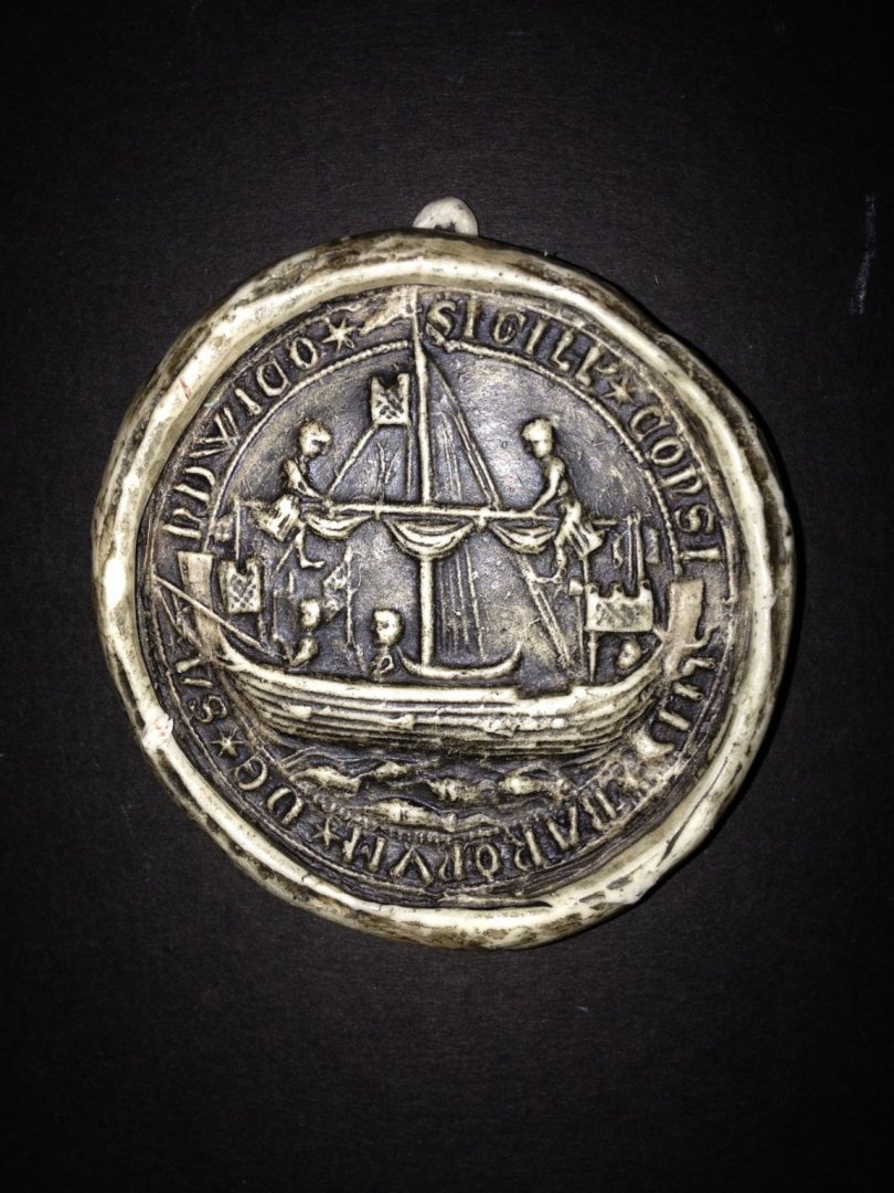
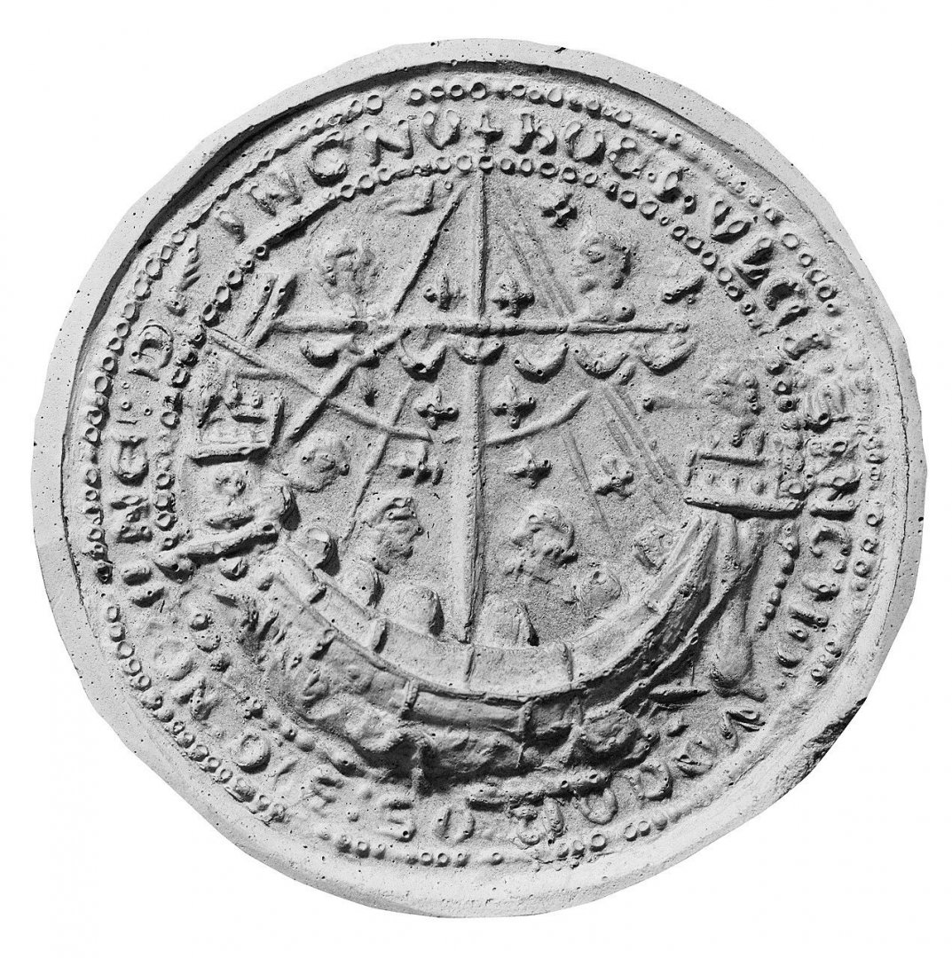
Exactly - but this seems to be an impression from the seal - look at the text around the outside of the seal; it's the right way around. Steven
-
While researching flags for the nef, I came across something rather weird - the town seal for Melcombe Regis (now part of Weymouth, on England's South coast) shows the coat of arms of Castile and Leon - in Spain! Except that it's a mirror image - but that might just be a mistake on the part of the seal engraver who may not have spotted that this is what happens when you make an impression from a seal (though he did get the lettering the right way around) I have no idea why - there's not very much info about Melcombe Regis on the internet (even Wikipedia has let me down!), let alone anything about a Spanish connection. Strange. Steven

-
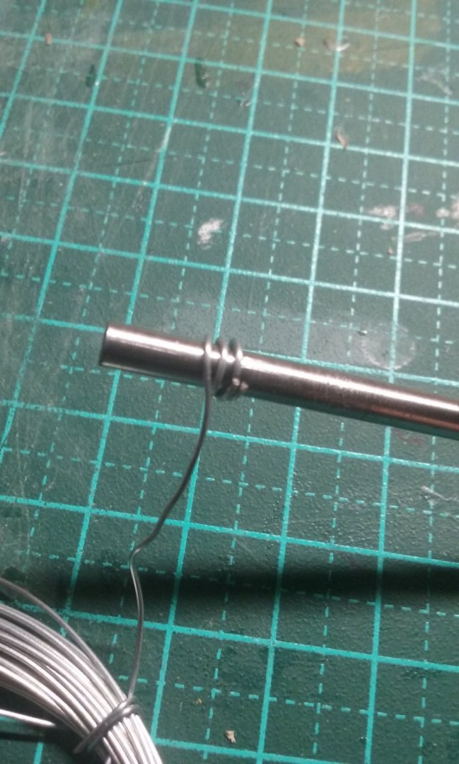
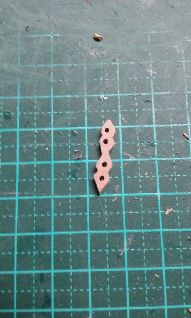
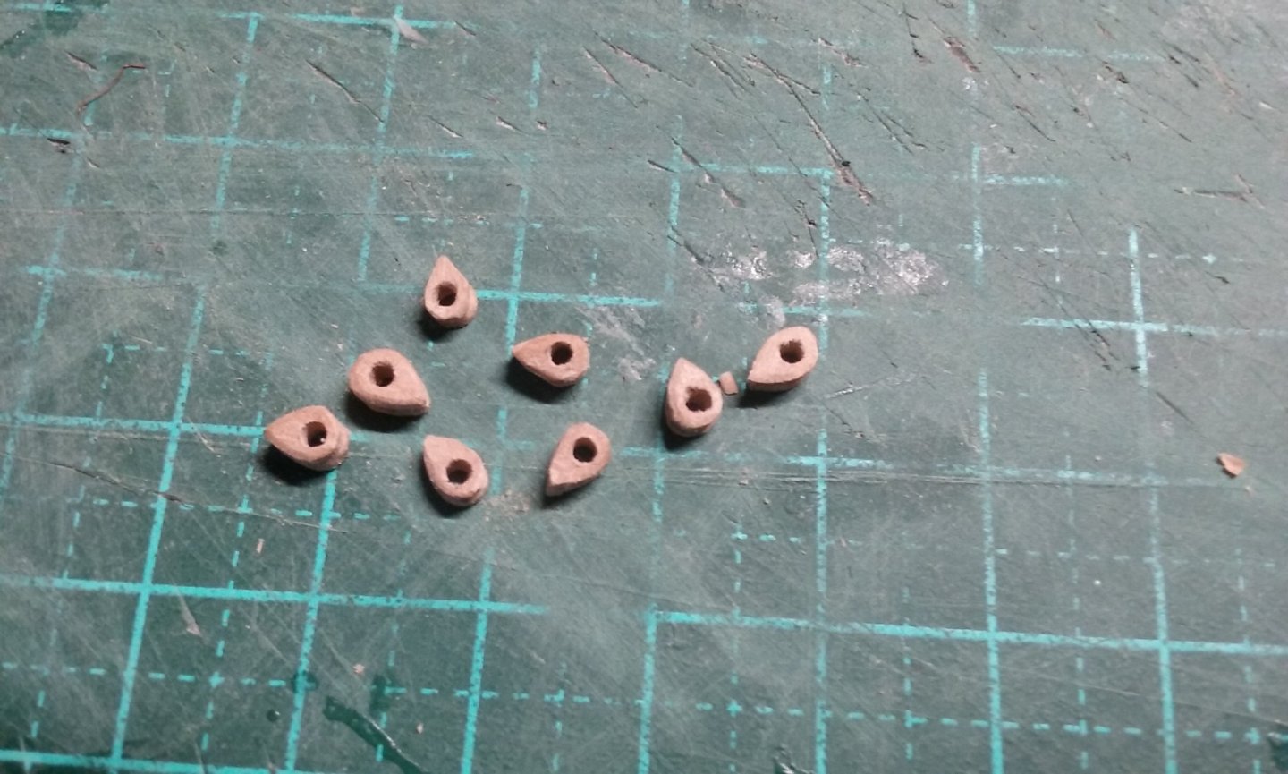
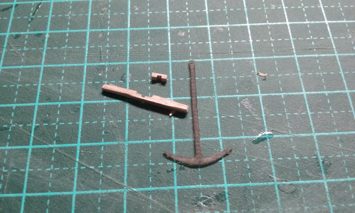
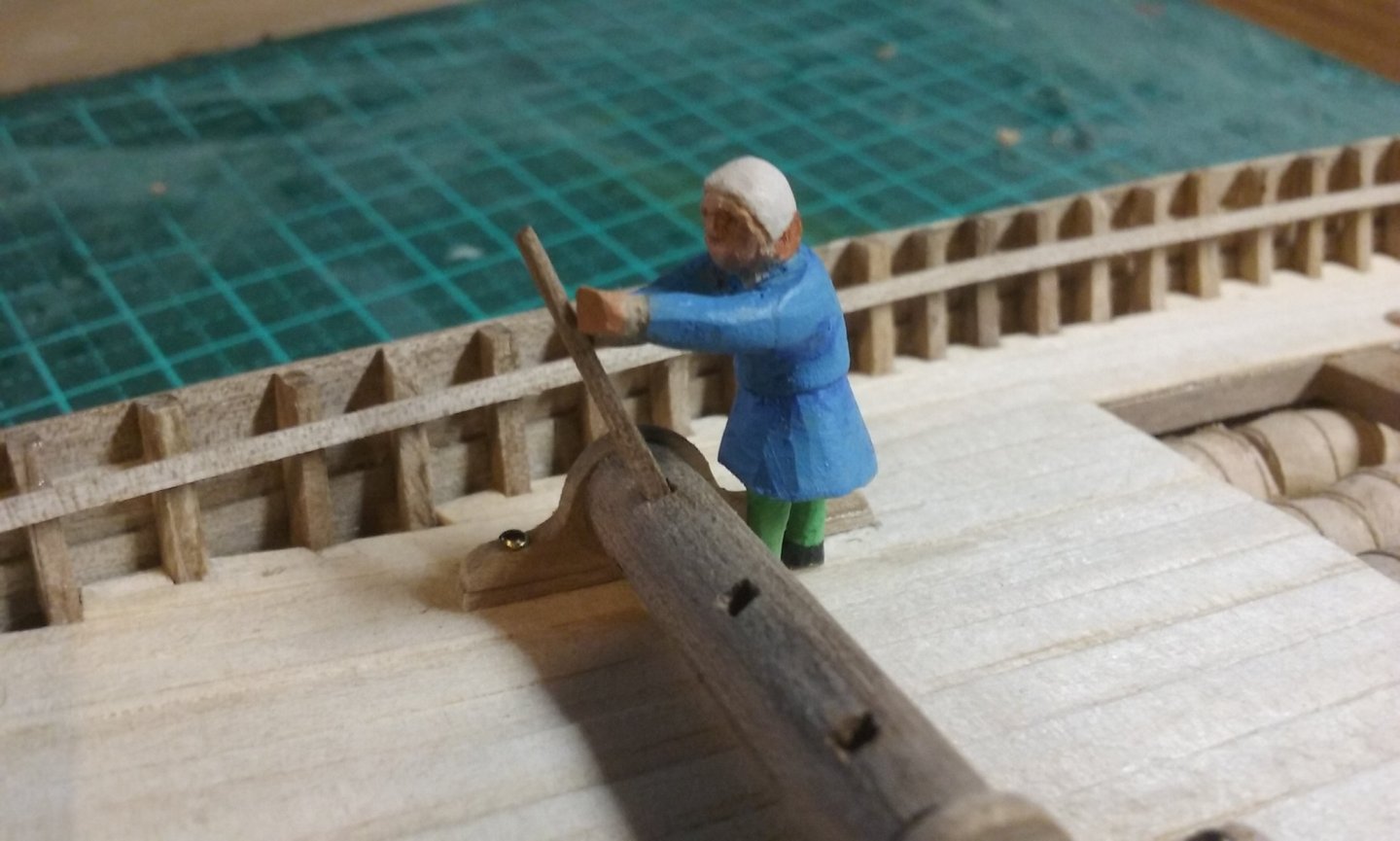
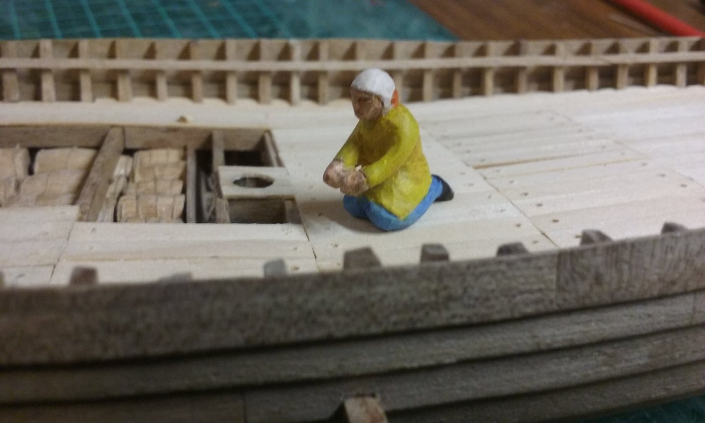
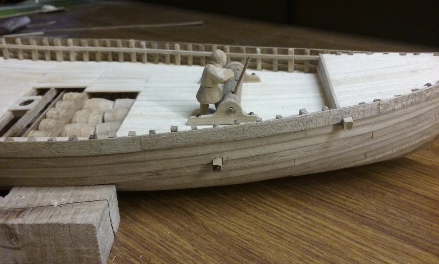
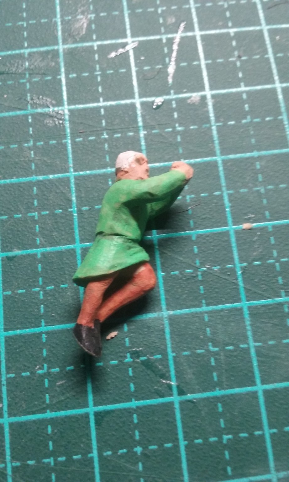
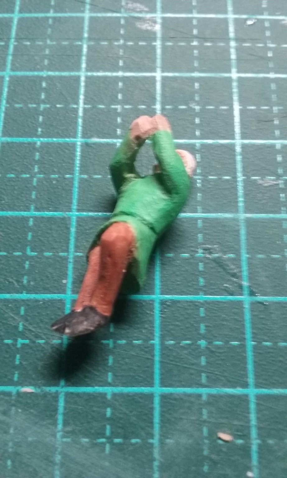
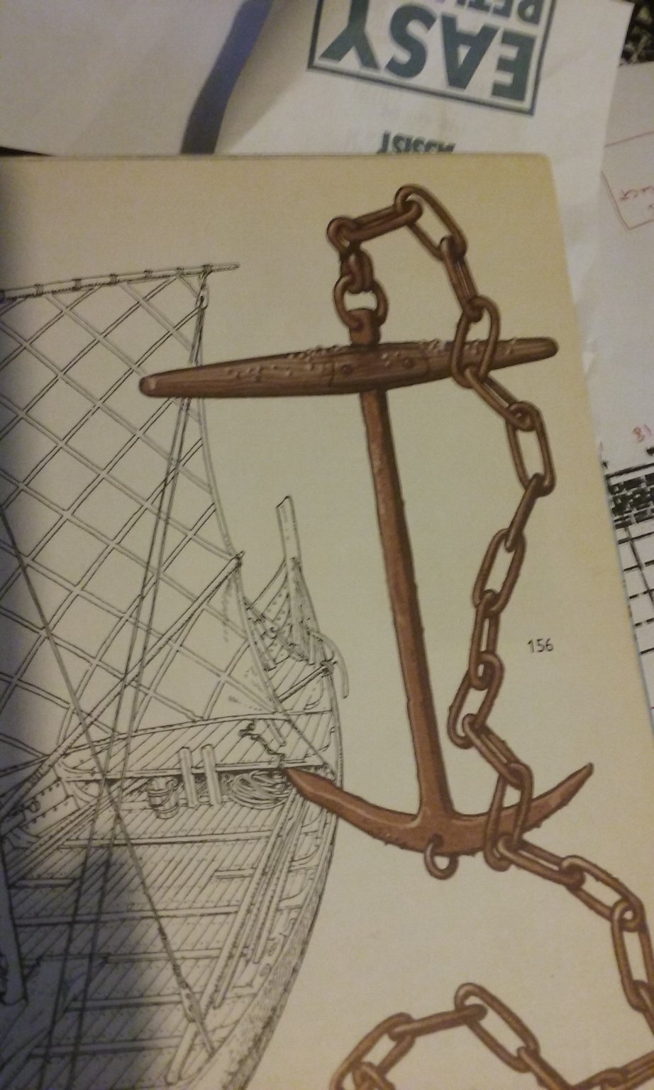
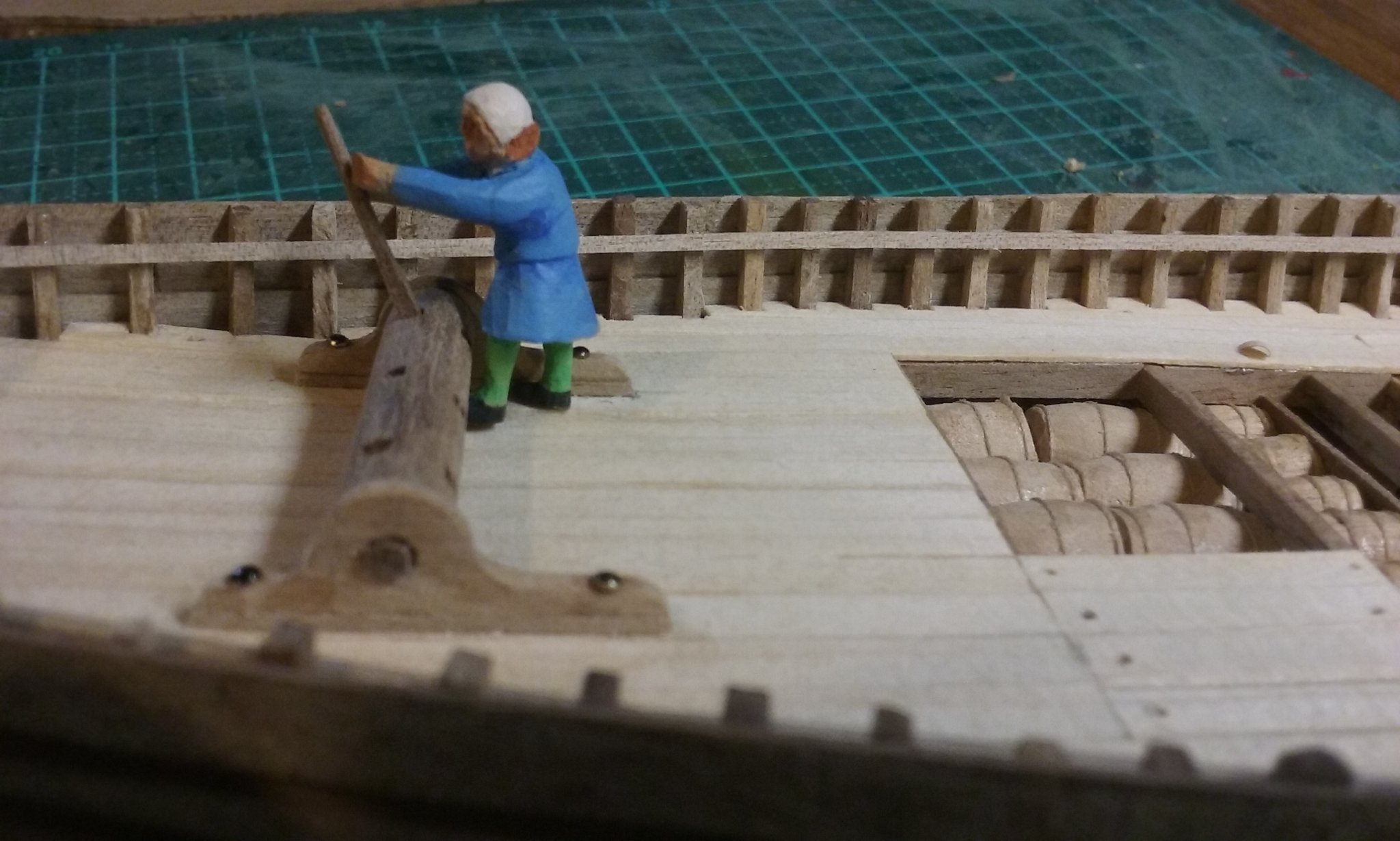
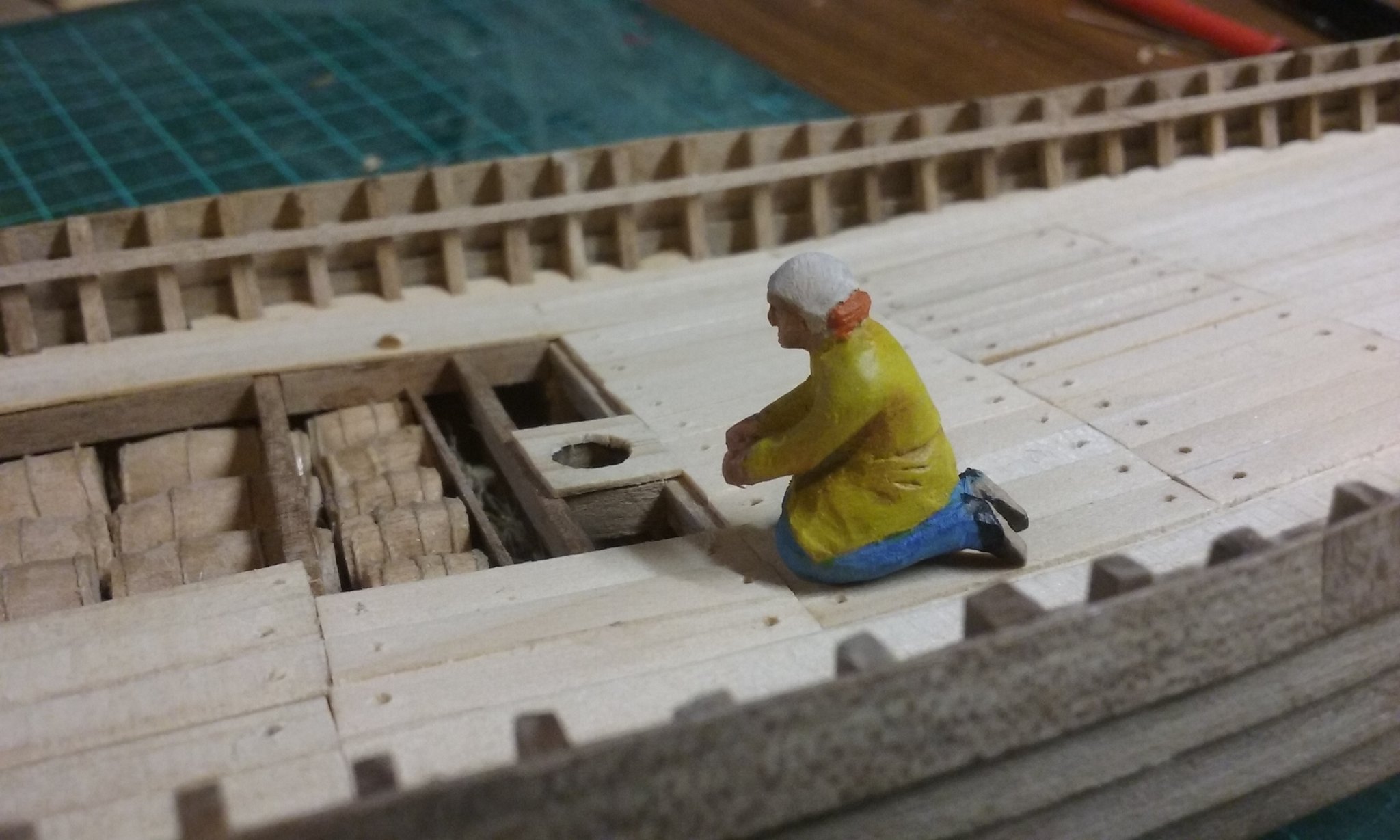
Thanks everybody for the likes and comments. Here's the guy on the windlass - I mentioned his arms were wrong, so I've changed them. In the photos one arm's already done, and you can see how I made and inserted new arms. And here he is complete, pained and dry fitted in place. And also the guy who's replacing the removable deck planks. Note - the funny hats are called coifs and were the height of fashion at the time. As a side note, contrary to what s shown in the movies (and beautifully sent up in Monty Python and the Holy Grail), people in the Middle Ages didn't all wear mud-coloured clothing - or black. Natural dyes - madder (red), woad (blue) and about half the plants you come across every day (yellow) produce some absolutely beautiful colours, which can then be combined to produce greens, oranges, pinks and a whole range of variations on the basic colours. To fix the lower ends of the shrouds, the earliest deadeyes I've been able to find are from the Bremen cog of 1380, over 100 years later than this nef. But the Gokstad ship's rigging pieces are from the 10th century, even further away in the other direction. As a compromise I decided to do hearts for the shrouds, as a step in the evolution toward deadeyes. And I'm very fortunate in that henrythestaffy 3d printed and sent me some anchors taken from a Viking find. The stock is made from wood, based on another Viking find, as shown. Note the interesting way of attaching the stock to the shank. Looks to me as though that would be a source of weakness, but it seems to have been used, so I'm going ahead with it. More to come . . . Steven


- 327 replies
-
- 10
-
-
Nicely organised shipyard, and that model is really starting to look good. Regarding mistakes; we all make them, but fortunately wood is a very forgiving medium, so a lot of the time you can repair your mistakes. And if not, a lot of the time the mistakes are only visible to you, not to anybody else. And every time you make a mistake you learn something for next time. Keep up the good work, mate. Steven
-
I've put together a Pinterest page with all the contemporary pictures of caravels I've collected over the years - it's at https://www.pinterest.com.au/lowe1847/caravels/ - I hope that helps. Steven
-
I'm loving the research on this one. It's great to have this information available. In particular I like the information on the conversion of the guns by adding reinforcing rings. A clever and elegant (and economical) solution to updating old guns to serve new needs. Overall, fascinating stuff! Steven
-
I don't know if you already have this, but there's some wonderful contemporary photos of Charles Martel here - https://military.wikireading.ru/35533 Steven
- 132 replies
-
- 4
-
-
- charles martel
- battleship
- (and 1 more)
-
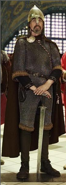
Thanks, Mark. Perhaps more about my pickiness. Maybe I should have been wearing mediaeval clothes (I do have them, you know!) Steven
-
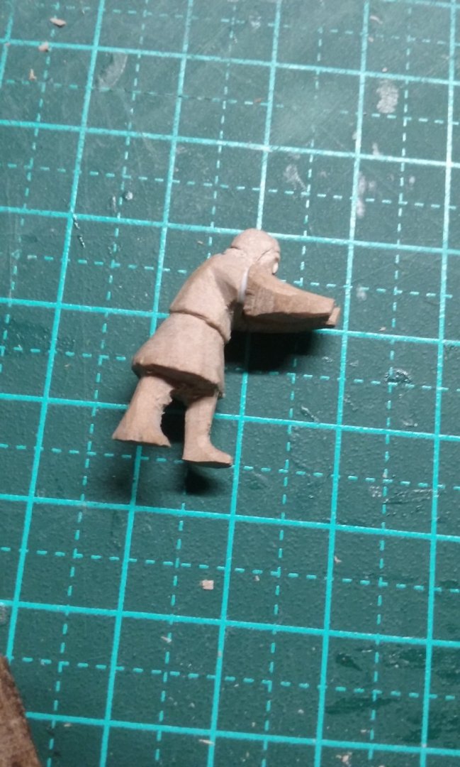
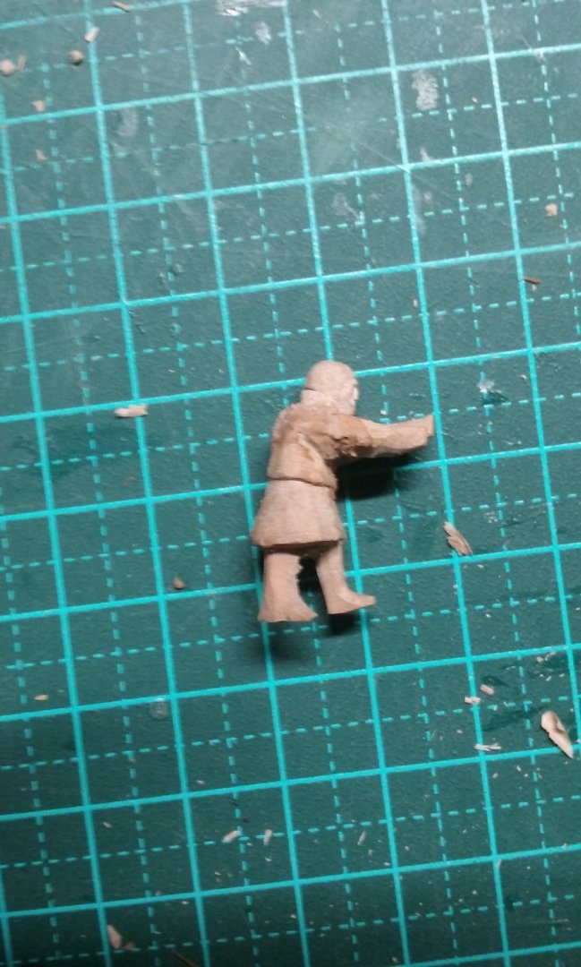
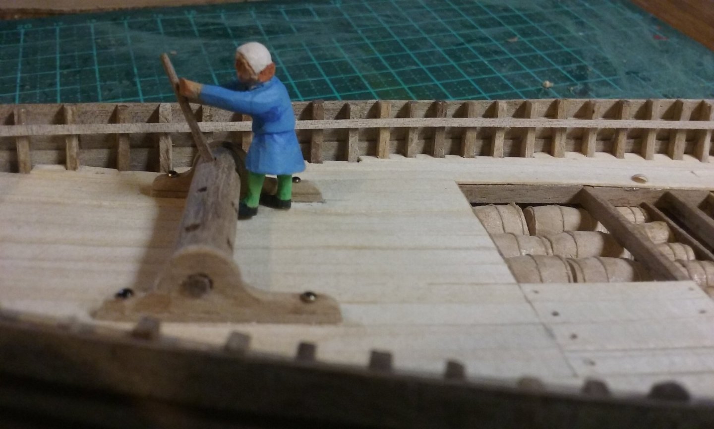
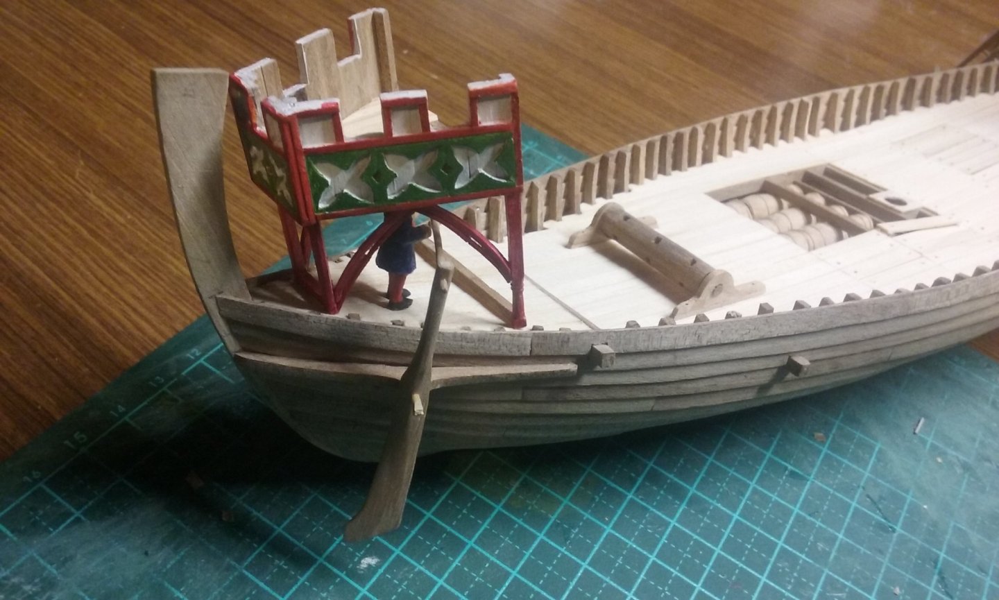
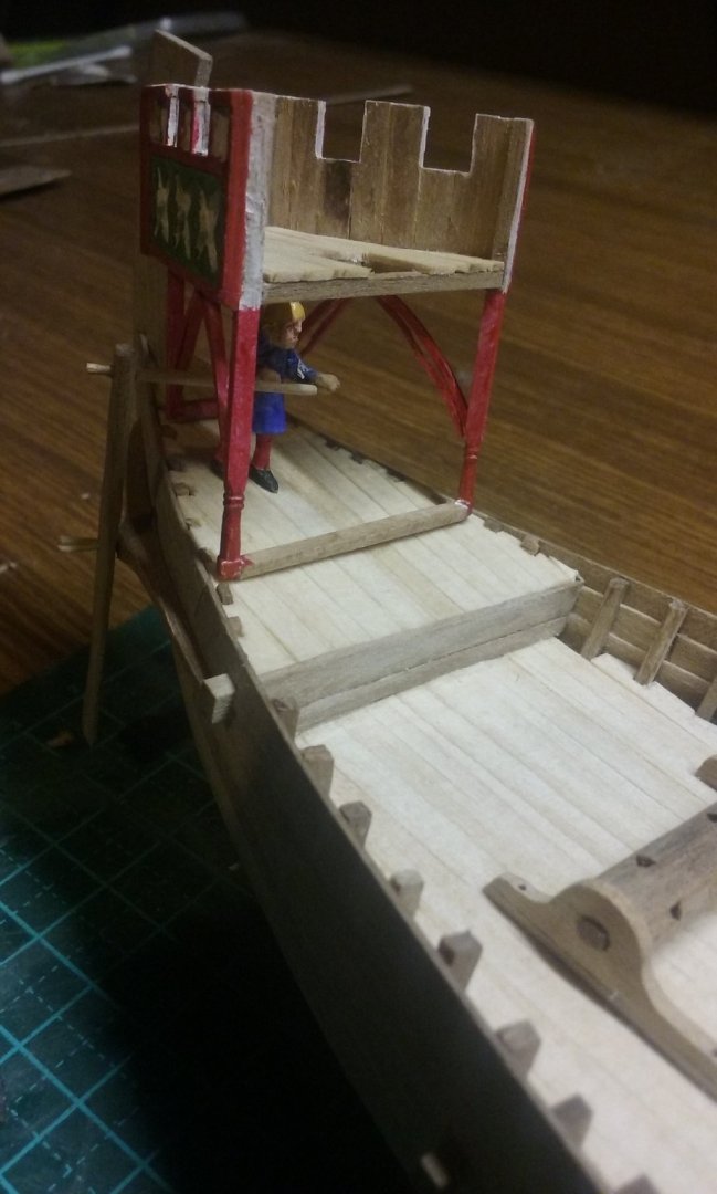
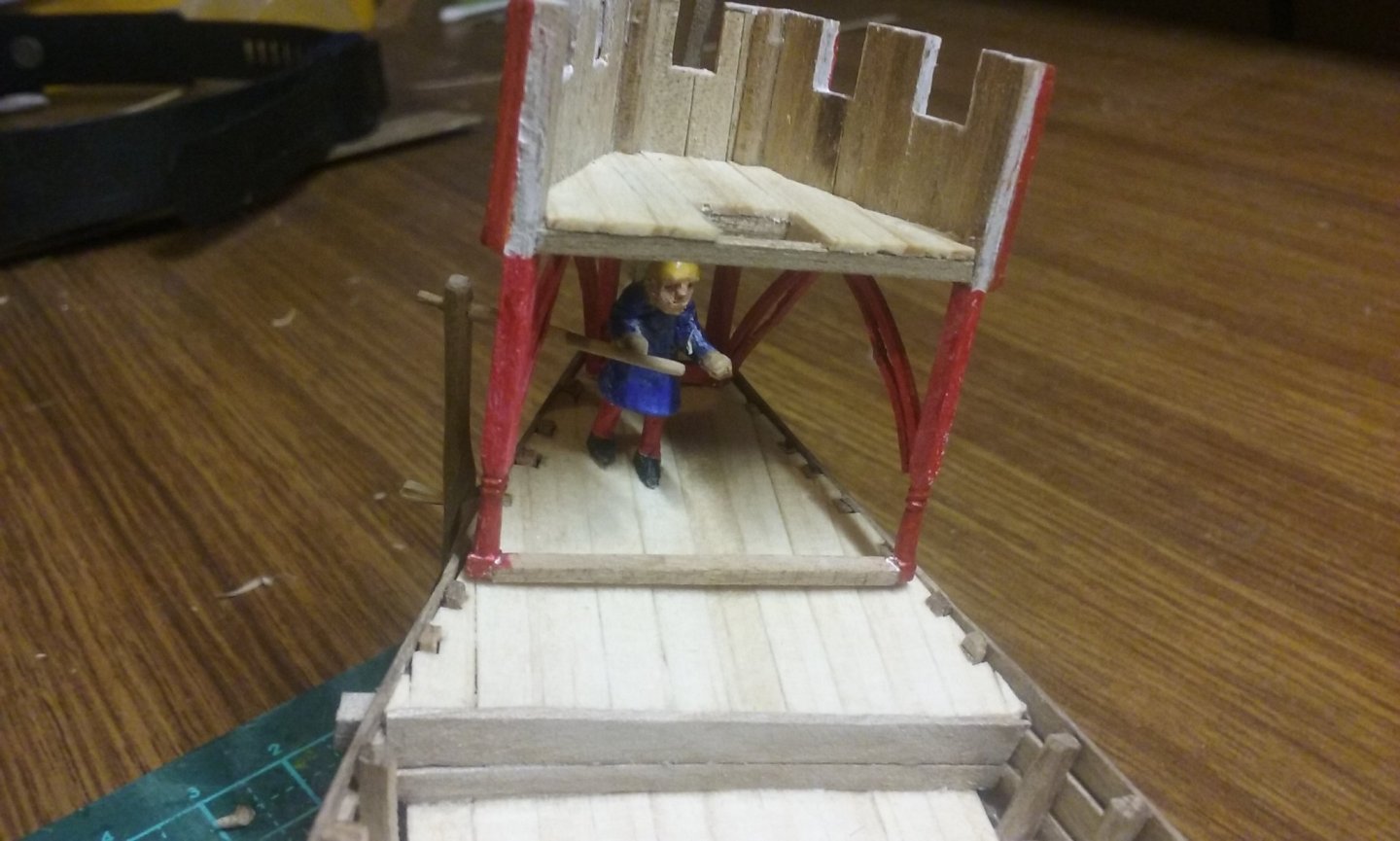
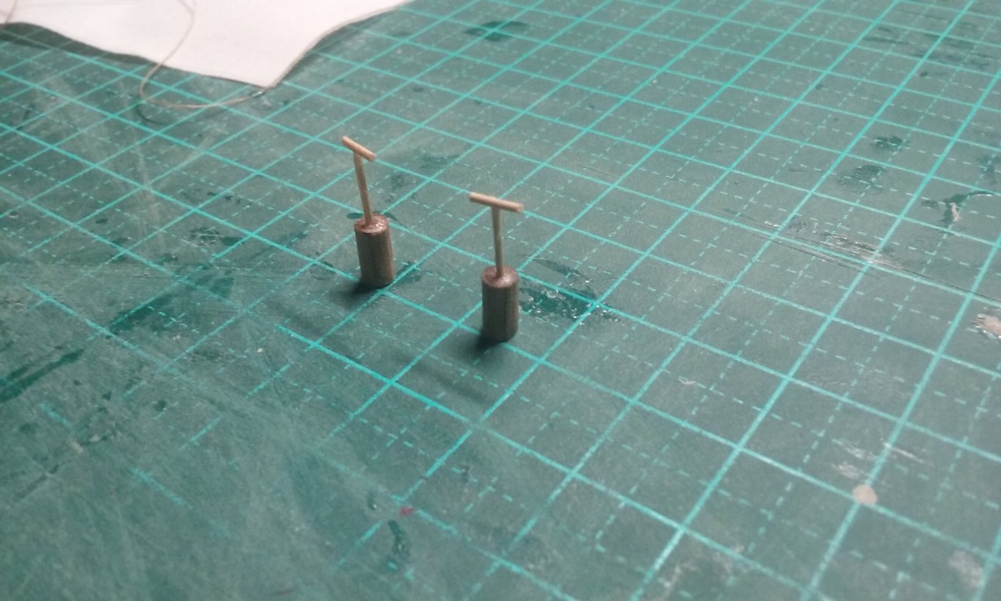
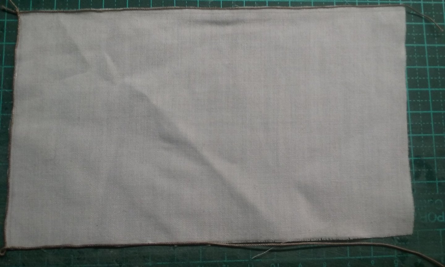
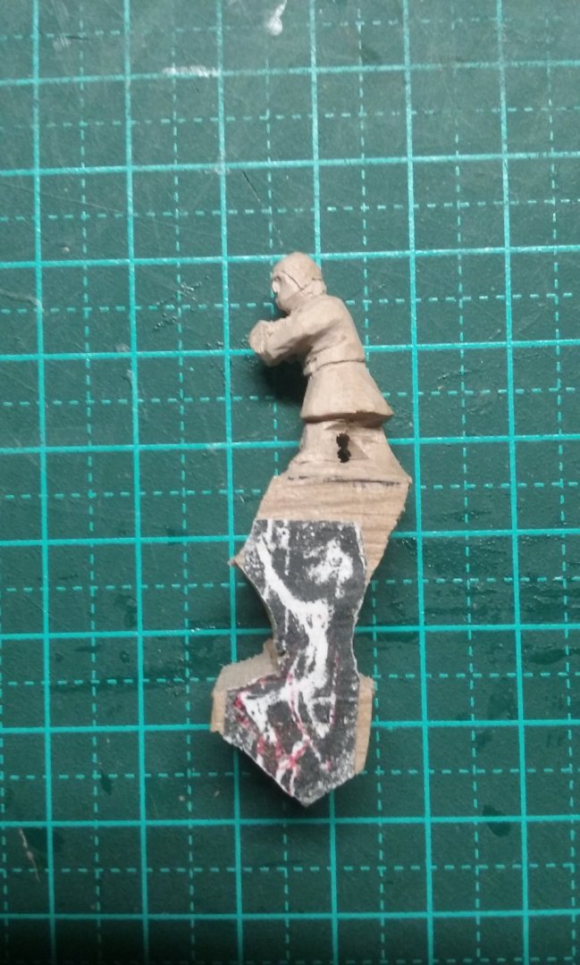
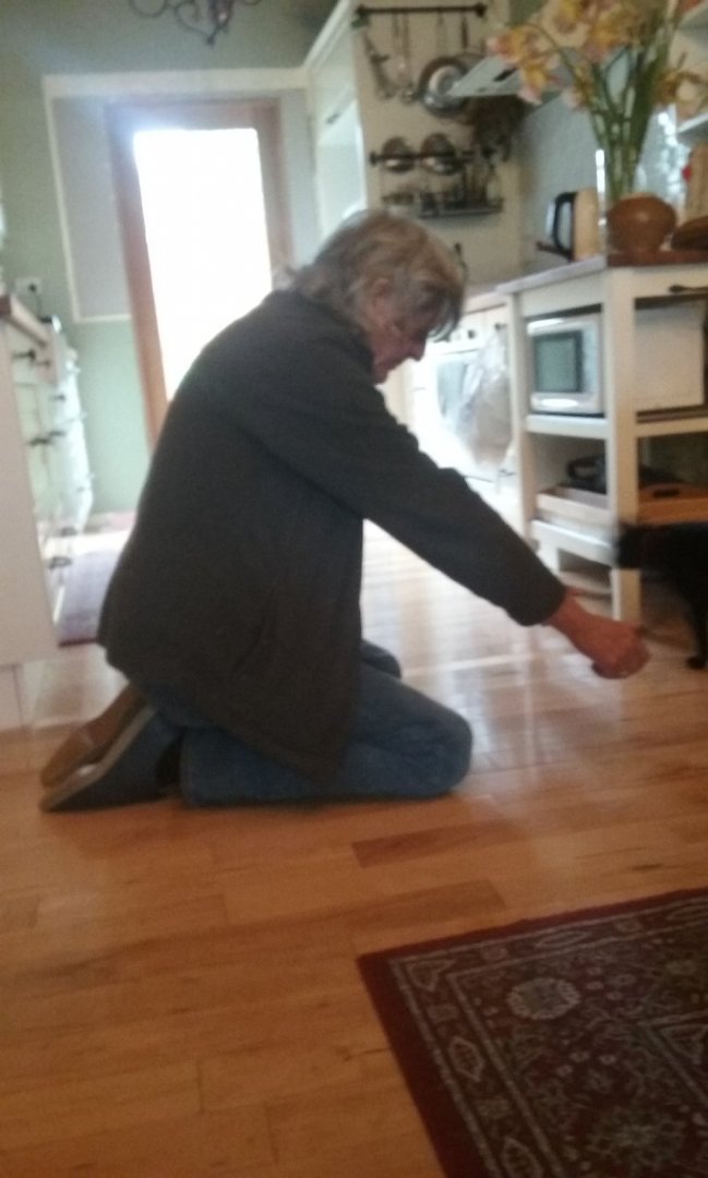
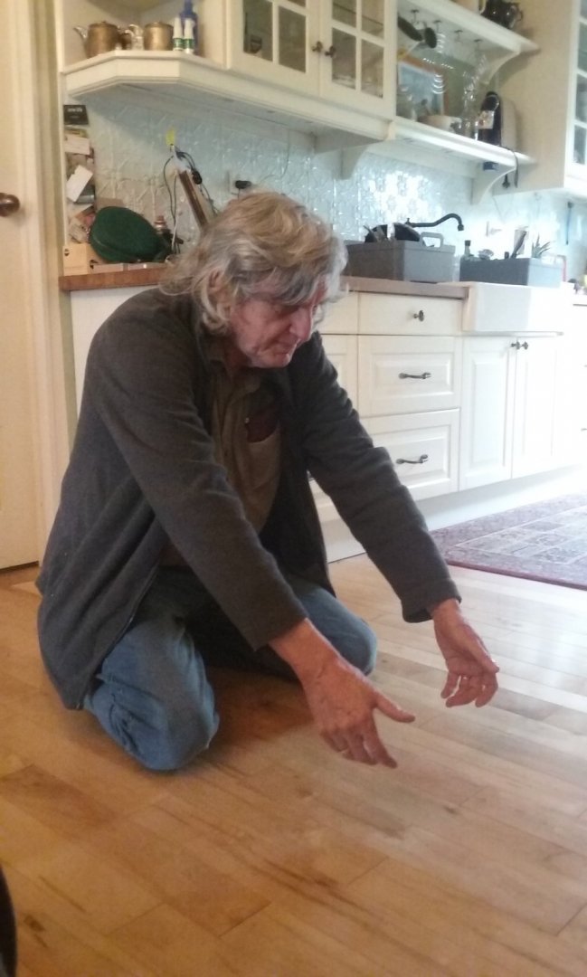
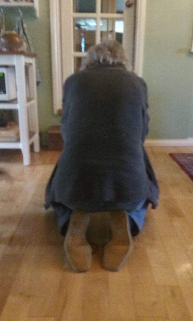
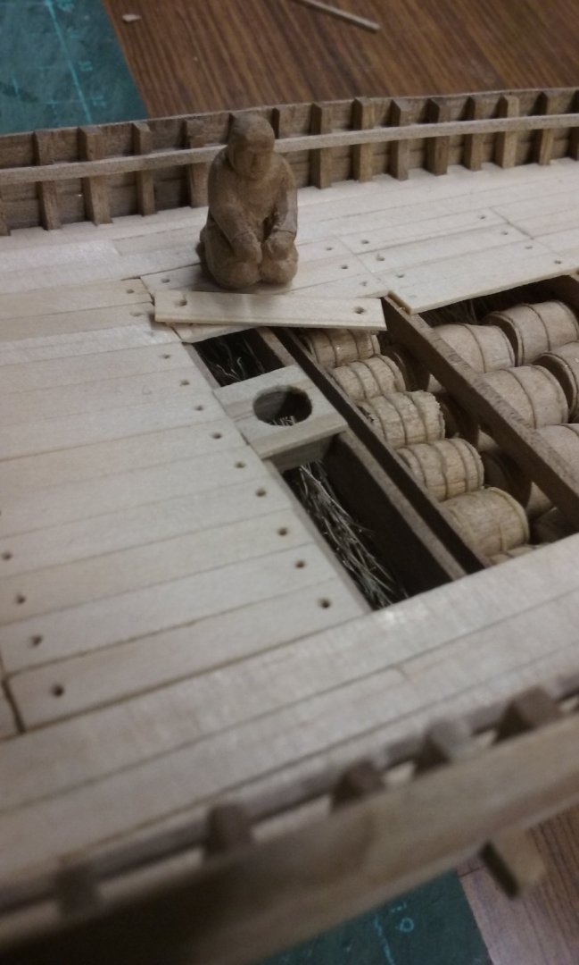
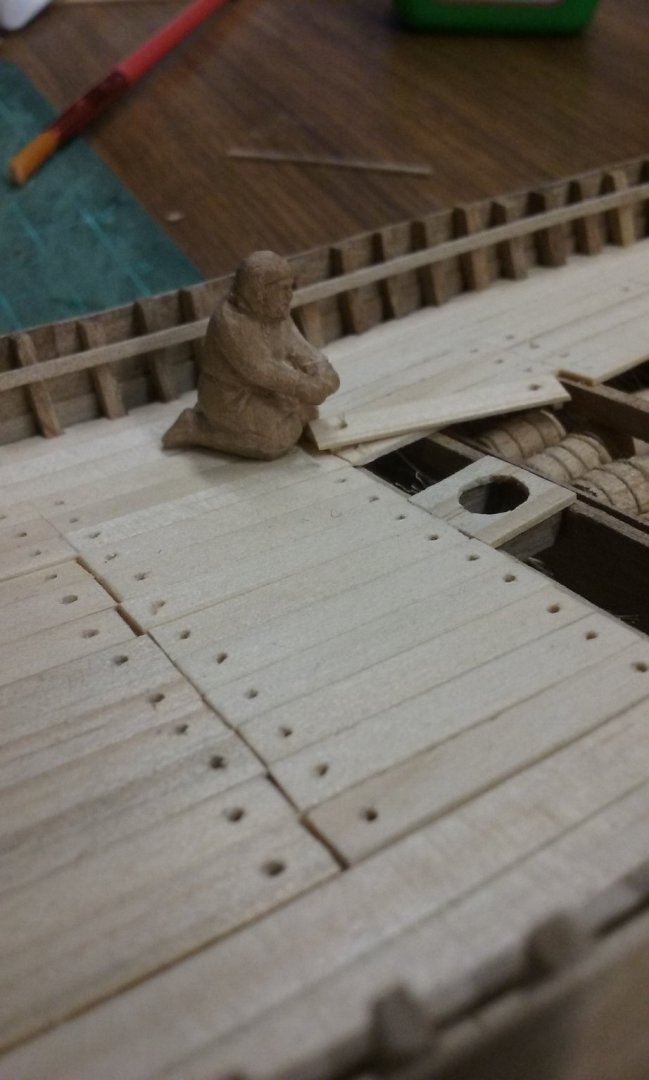
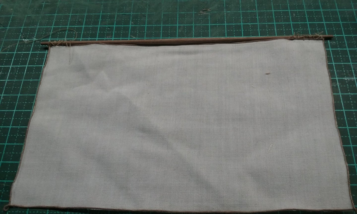
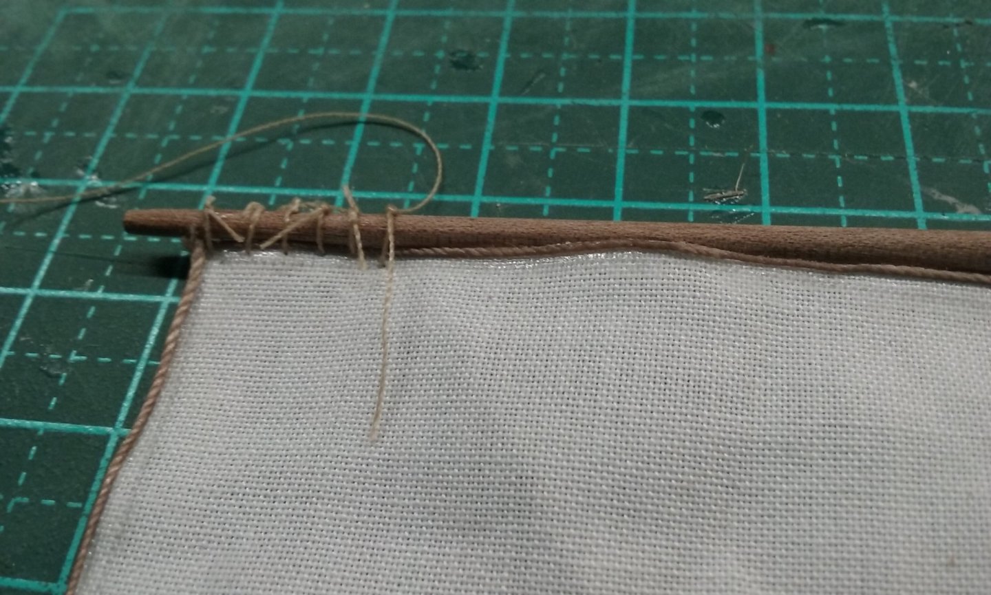
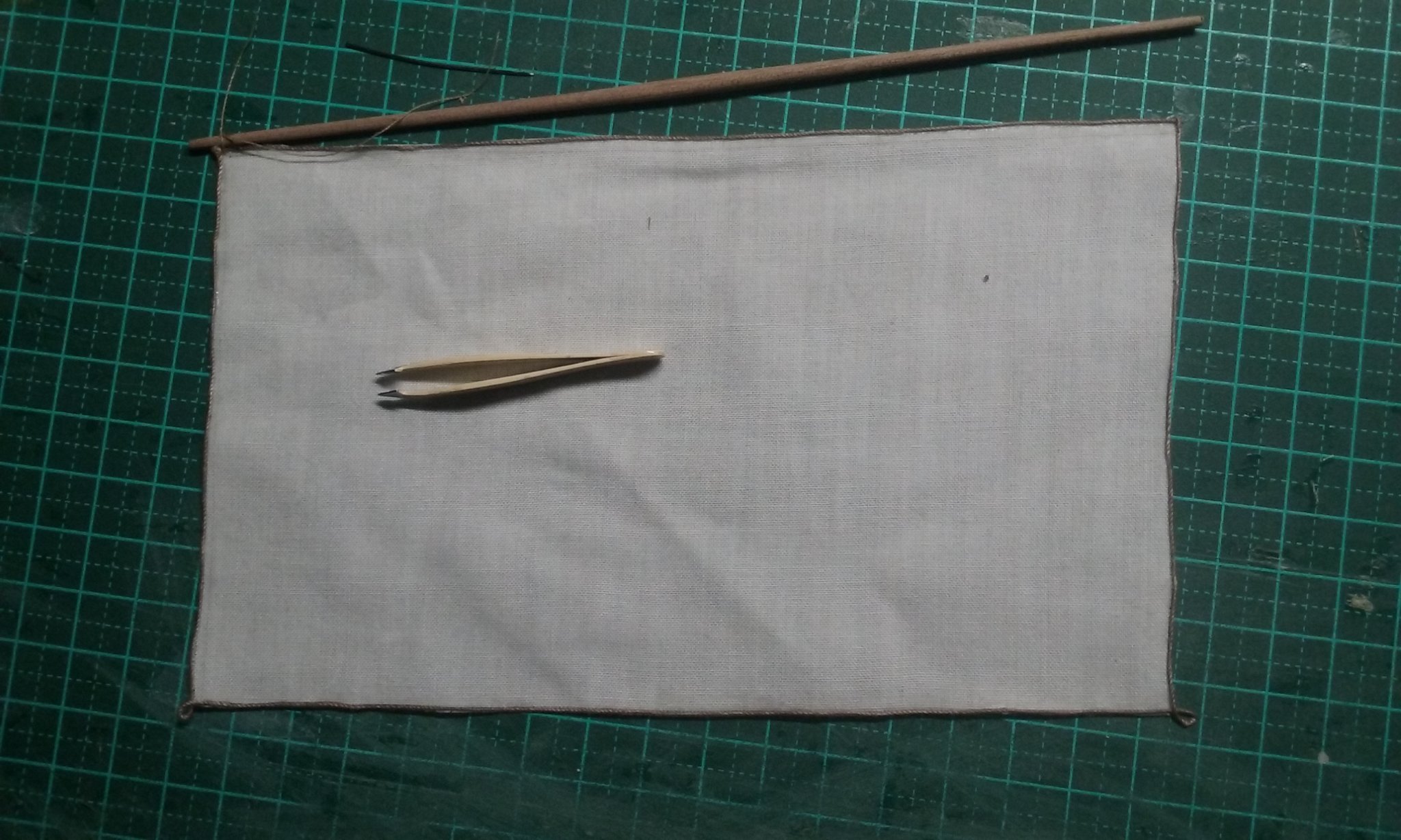
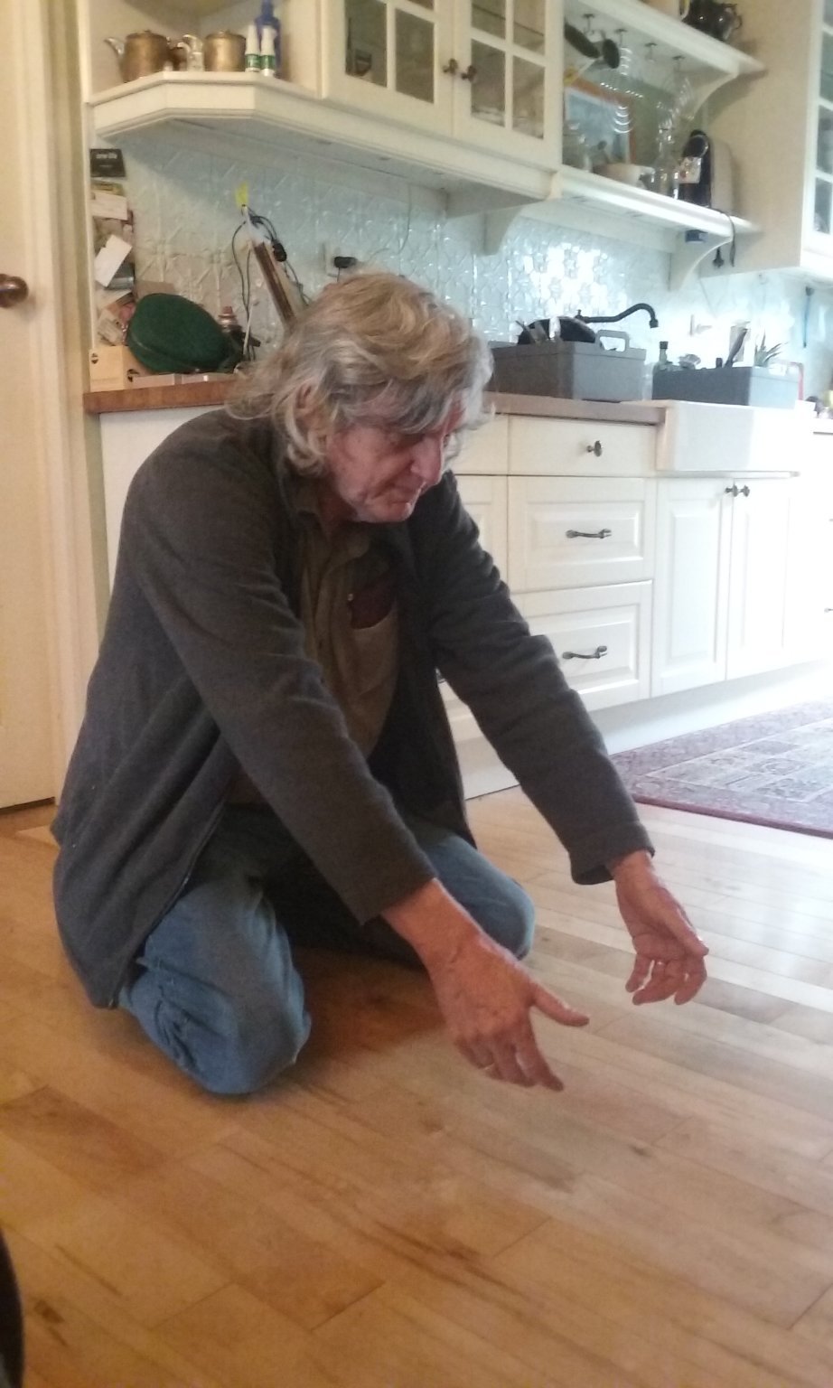
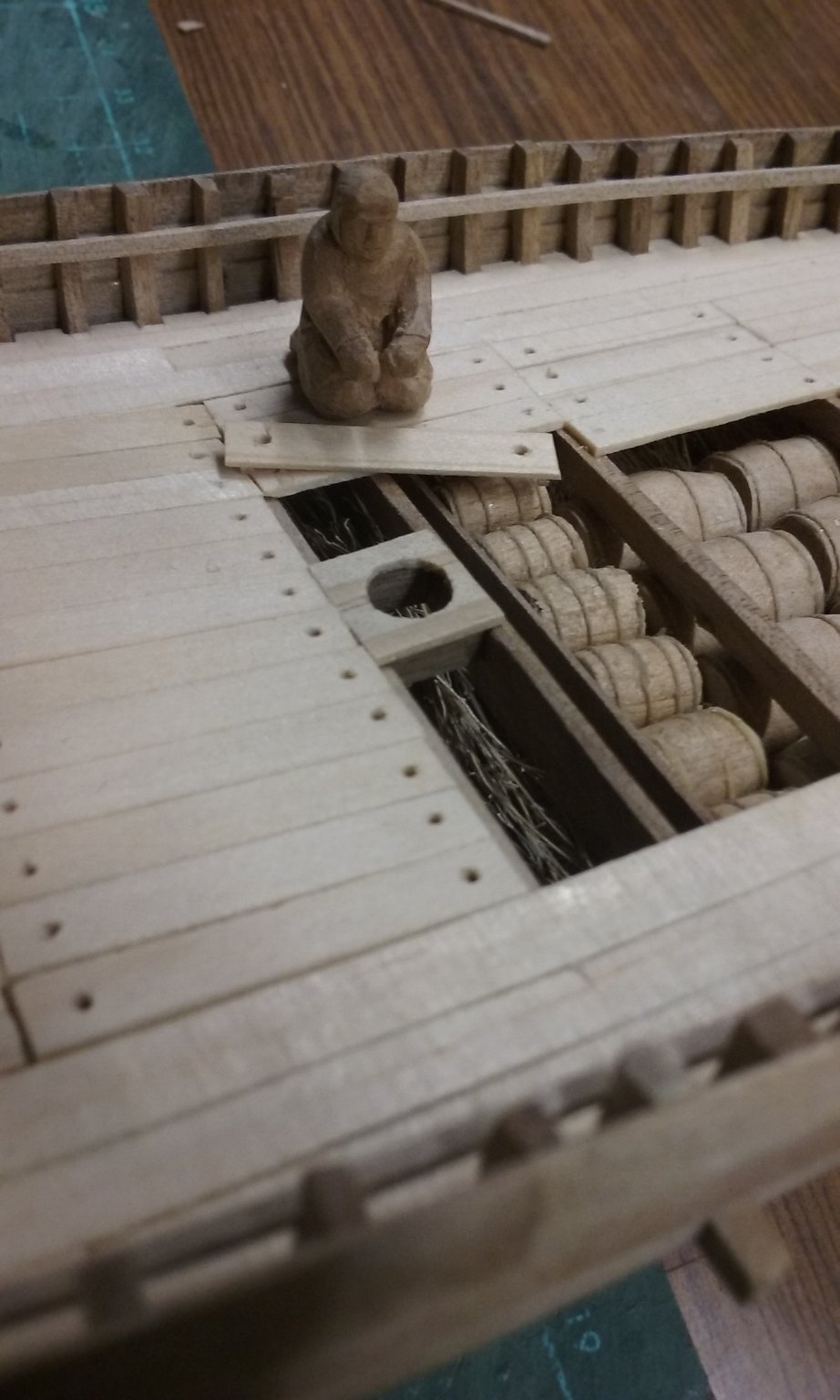
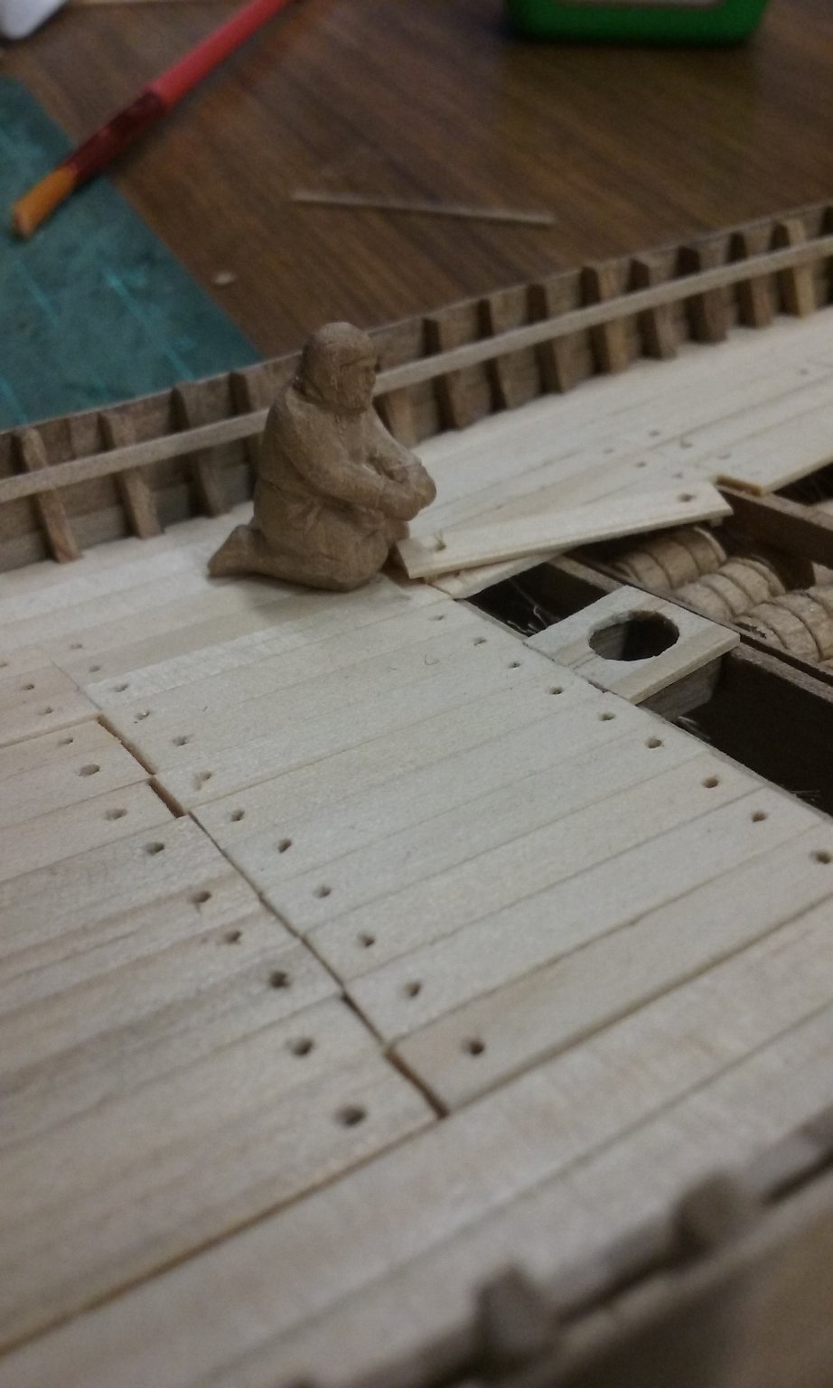
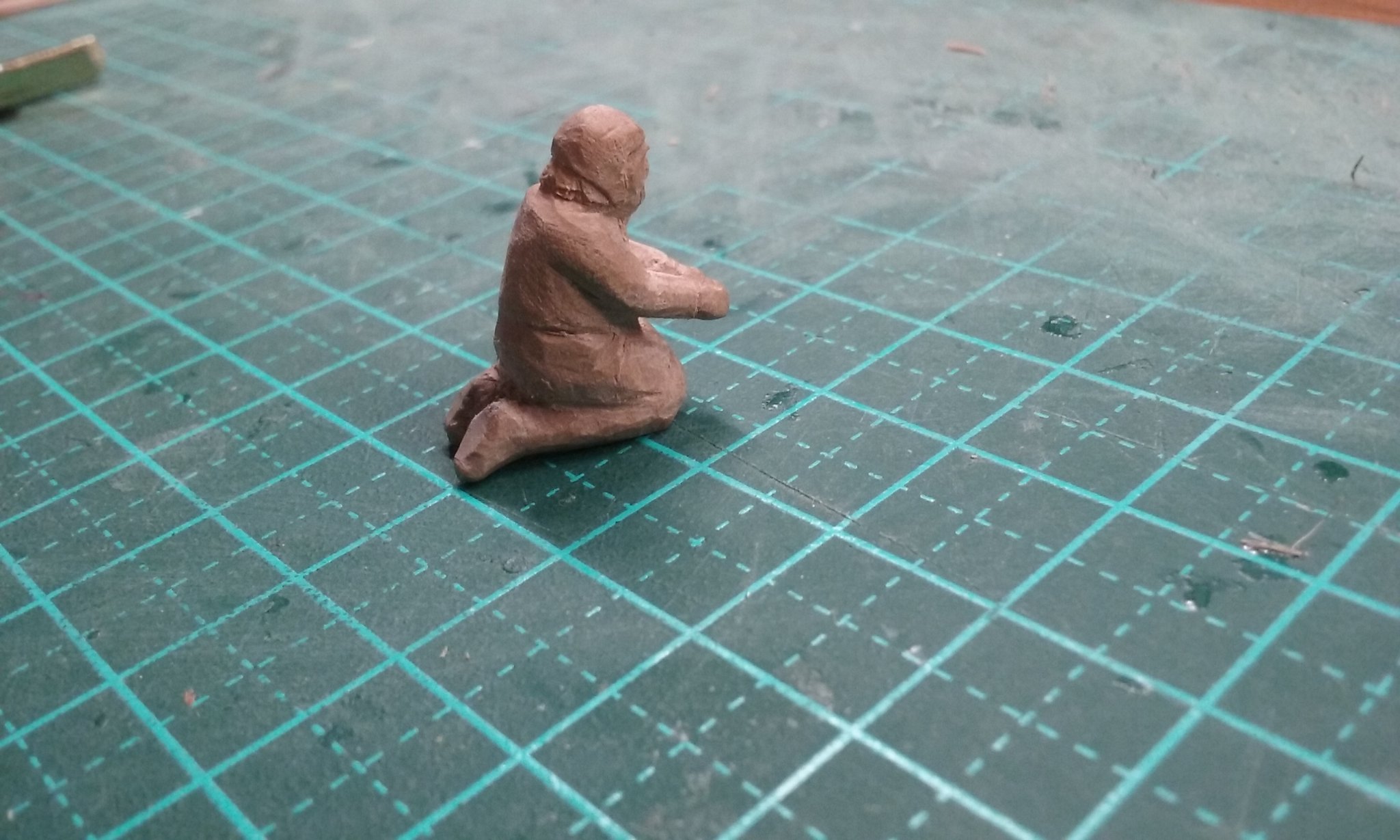
Aligning the side-rudder. I had to get the locations of the horizontal rudder support, the pivot, the tiller, the aftercastle and the steersman (and his hands) all to line up with each other. Took quite a bit of experimentation. All temporarily fitted. I used a couple of spots of glue to keep the castle and the steersman in place while I worked everything out, and later used isopropanol to free them. For the final set-up I'll have to move the steersman over a bit toward the side of the ship so his hands line up with the tiller exactly right. Here are the pumps. I'll probably put them between the windlass and the aftercastle. Starting on the sail. I've made it shorter than the real thing, as it'll be furled and I don't want it too bulky. I may yet need to cut more off it to get the bulk right - we'll see. Adding the boltropes (I glued them on rather than sewing, which would be too large to get to look right at 1:75 scale). Beginning on the robands. Two more figures under way. One replacing the removeable planks over the hold as the ship gets under way, the other working the windlass to raise the sail. (The guy below will be climbing a halyard to unfurl the sail, but I'll get onto him later) More on the guy replacing the planks: At which point I asked my beloved wife to take some photos of me doing it so I could get the positions and angles right. As it turned out, most of it was pretty close to right. But I wanted to get such things as the angles and positions of the knees and feet correct. The only thing is that he's not really leaning over far enough to be sliding a plank across the deck. I'll have to have him holding one end of it up in the air a bit. And the guy on the windlass. Unfortunately, this figure is also not leaning over far enough. You can see he won't be able to reach the windlass bar. I thought of cutting him across the middle and changing the angle of his torso so he could reach the bar, but I think instead I'll re-do his arms so he's reaching out further. More to come in a while. Steven


- 327 replies
-
- 15
-
-
-
TWEEZERS - a tool to hold a tiny intricate item it's taken you hours to make, and flick it into another dimension, from which it returns just as you finish making its replacement. SANDPAPER - A substance for abrading holes in planking. SCROLL SAW - a device for sawing the wrong side of a line. COPING SAW - a tool for cutting a wavy track both sides of a line.
- 37 replies
-
- 11
-
-

-
scalpel - A tool designed to exert uneven torque as you're carving something delicate so the blade will snap in half at the most inopportune moment and slice off large portions of finger/thumb. craft knife - a tool designed to unwind just as you're carving something delicate so the blade will fall out and slice off large portions of finger/thumb. Angle grinder - A tool designed to cut through its own power cord. Sharpening stone - a tool designed to make a blunt tool into a very blunt tool. Lathe - a tool designed to fling chisels across the workshop. Steven
-
No way. Put it in the water and it would sink . . . Steven
-
More power to you, Antony. I wouldn't have the patience. You're doing a brilliant job. And I thought I was an Old Man of re-enactment having started in 1987! Steven
-
Aah, memories. What year(s) was that? Steven
-
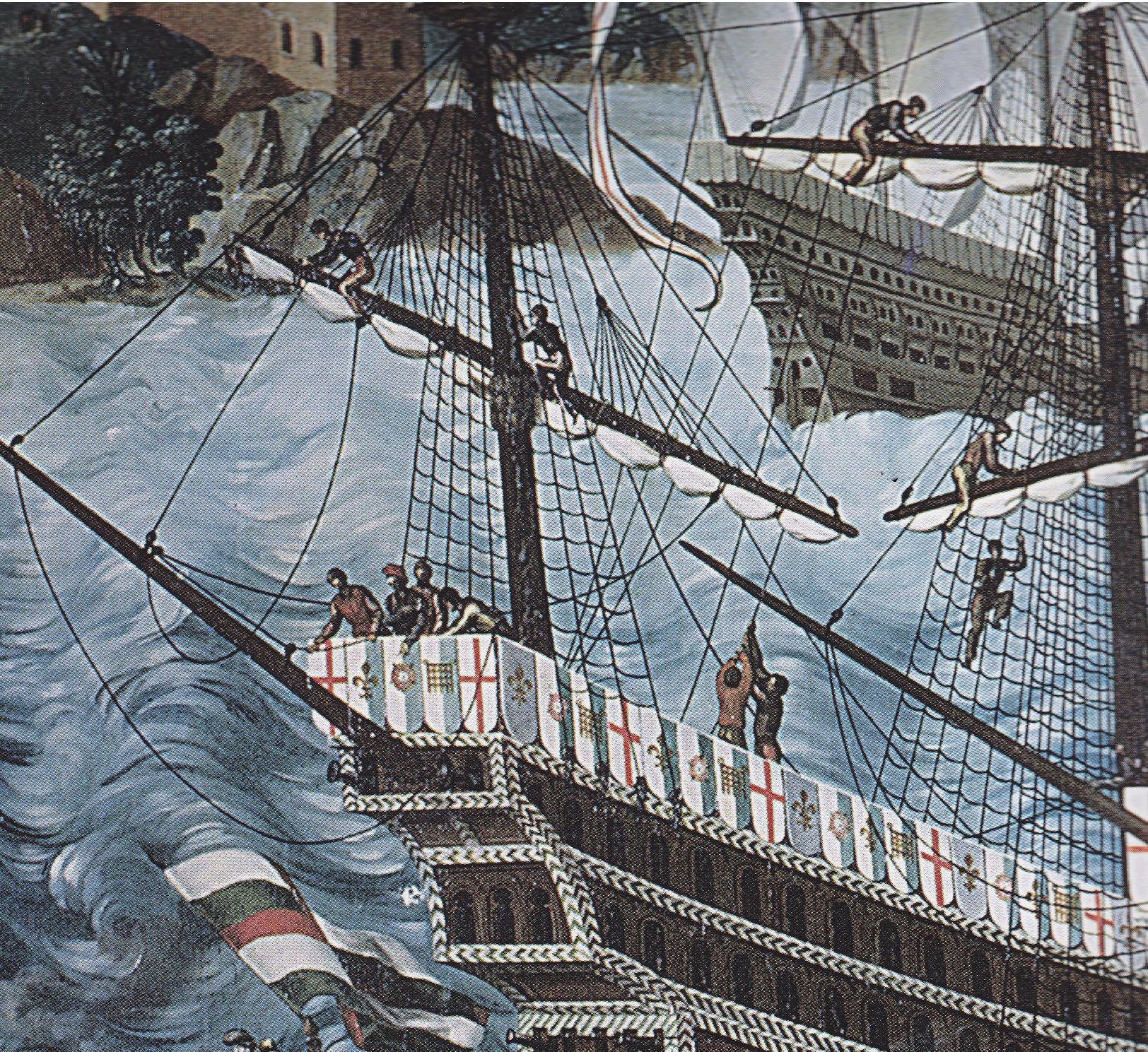
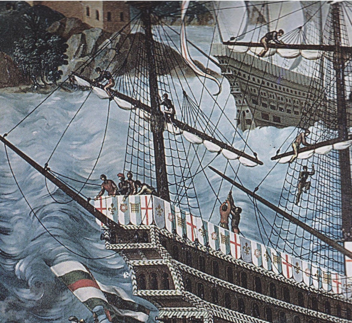
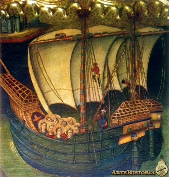
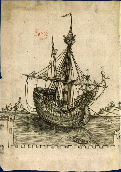
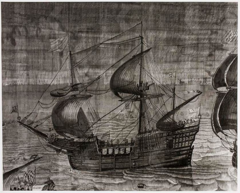
Yep. They seem to have been very brave (or foolhardy). But then it's probably the old story, till footropes were invented, nobody felt the lack . . . You may be right about dropping the yard to attach the sail to it, but it seems pretty obvious that to unfurl it once it was up, they climbed up and sat astride the yard. I don't know if they would have done the same to furl the sail - somehow it doesn't seem all that likely. Maybe they dropped the yard, sail and all, to furl it. When footropes came in - certainly not before 1545 - the second painting above is from that date. It would need a search through contemporary pictures of galleons to see if they had them - just did that, and no clear evidence of footropes in use, but this Dutch pic from as late as 1629 (It's not very clear, I'm afraid) still seems to show someone straddling the mainyard. [Edit] According the R.C. Anderson in The Rigging of Ships in the Days of the Spritsail Topmast, "It is impossible to say when they did first appear, but I believe it to be a fact that the first evidence for them is in Bond's The Boatswain's Art" of 1642. Certainly they are not mentioned in the English books of 1620-40, such as Manwayring and Boteler." [/Edit] Steven
.thumb.jpg.2e58d46e9c060069c1cc700af4723bab.jpg)
-
Yes, there's so little reliable information from this period. I certainly wasn't trying to criticise your choices - I've been on my own voyage of discovery regarding windlasses. I've got zu Mondfeld's book - unfortunately he doesn't say what he bases this statement on, but assuming he's got the right information, there's every reason to make a polygonal windlass for a ship of this period. And these hulcs were in use for quite a long time, as well. apparently - I'm sure you've already seen this - https://nautarch.tamu.edu/class/316/hulk/ which states that the Hulkesmouth/New Shoreham seal, which sparked off the whole "hulcs had upside-down clinker" theory, dates to about 1295. Steven
- 186 replies
-
- 2
-
-
- keelless
- reverse clinker
- (and 4 more)
-
I've been fortunate enough to have received 3D printed anchors and deadeyes (TINY!!!) from HenrytheStaffy. Brilliant quality. Steven
-
Nah. It was all scripted. Foregone conclusion. Being an Anglo-Saxon freak, I was of course on the losing side (sigh). Steven


.jpg.10980ee7ccac7c5ca0b38978c9ed30c8.jpg)


.jpg.a14e4ae0c6efaa95fab3b8b00373784a.jpg)