Louie da fly
-
Posts
7,993 -
Joined
-
Last visited
Content Type
Profiles
Forums
Gallery
Events
Everything posted by Louie da fly
-
 But when you come to Ballarat, be sure to let me know you're coming and I'll show you around. Steven
- 110 replies
-
- 2
-

-
- Paddlewheeler
- Ballarat
- (and 3 more)
-
Nice work, Mikki. Coming along well. Steven
-
It's a very nice trip around the lake, nice views and just an enjoyable time. But just a heads-up - only on Sundays (it's run purely by volunteers), and subject to weather conditions (the lake can get a bit scary in high winds). Here's their Facebook page https://www.facebook.com/goldencitypaddlesteamer But I'm afraid they don't necessarily keep it updated as much as they should, so perhaps phone them beforehand to check if she's running that day. Steven
- 110 replies
-
- 2
-
-
- Paddlewheeler
- Ballarat
- (and 3 more)
-
Patrick, in Australian terminology, you're a dead-set legend! Perhaps this is not the time to repeat the joke about the Scottish soldiers and the wire brush? Steven
-
'Good beginning is half won'. Or - 'If you're given two hours to cut down a tree, spend the first hour and a half sharpening your axe.' Steven
-
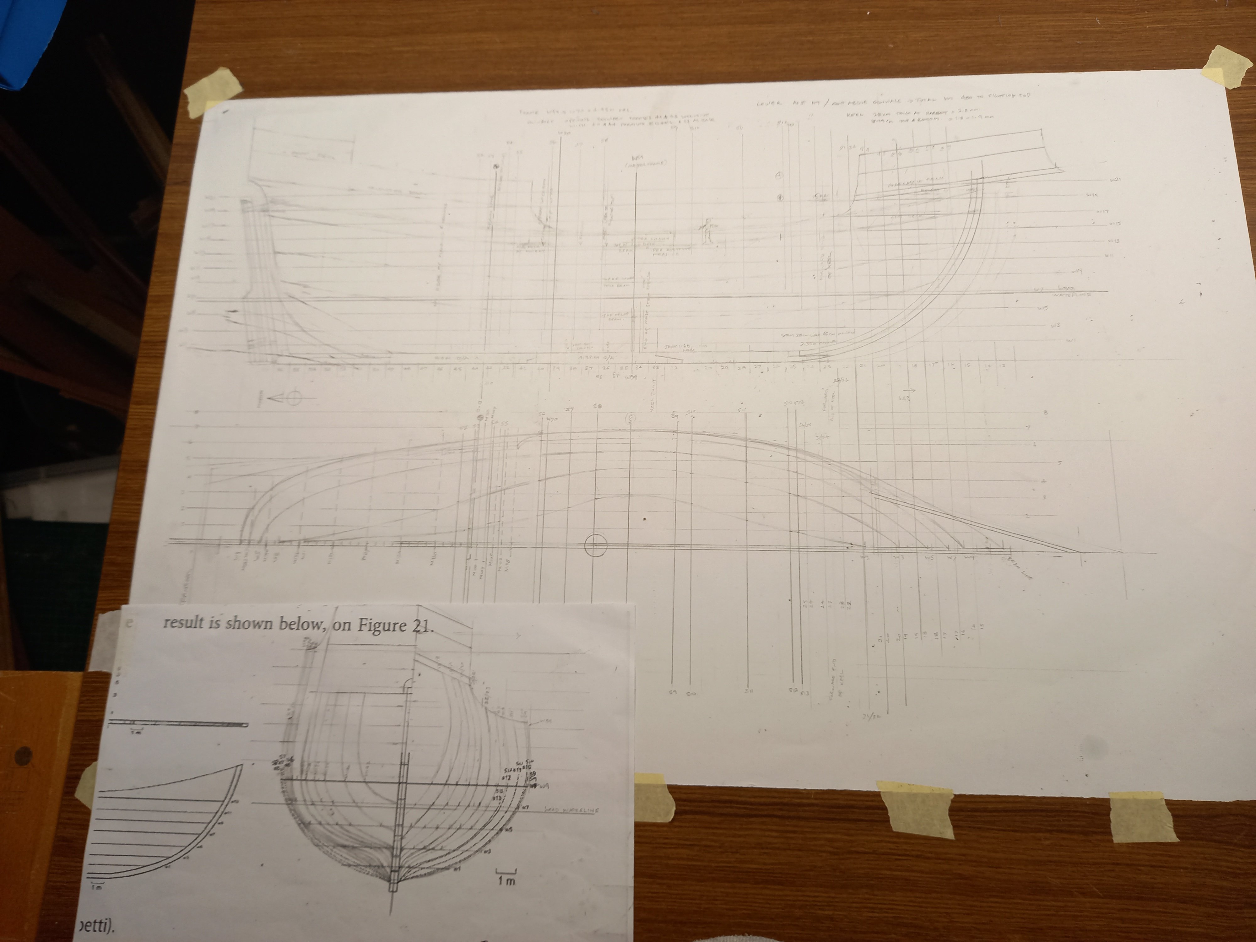
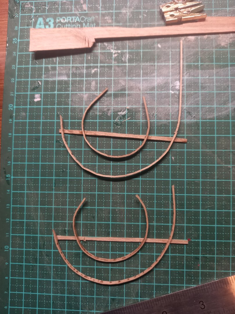
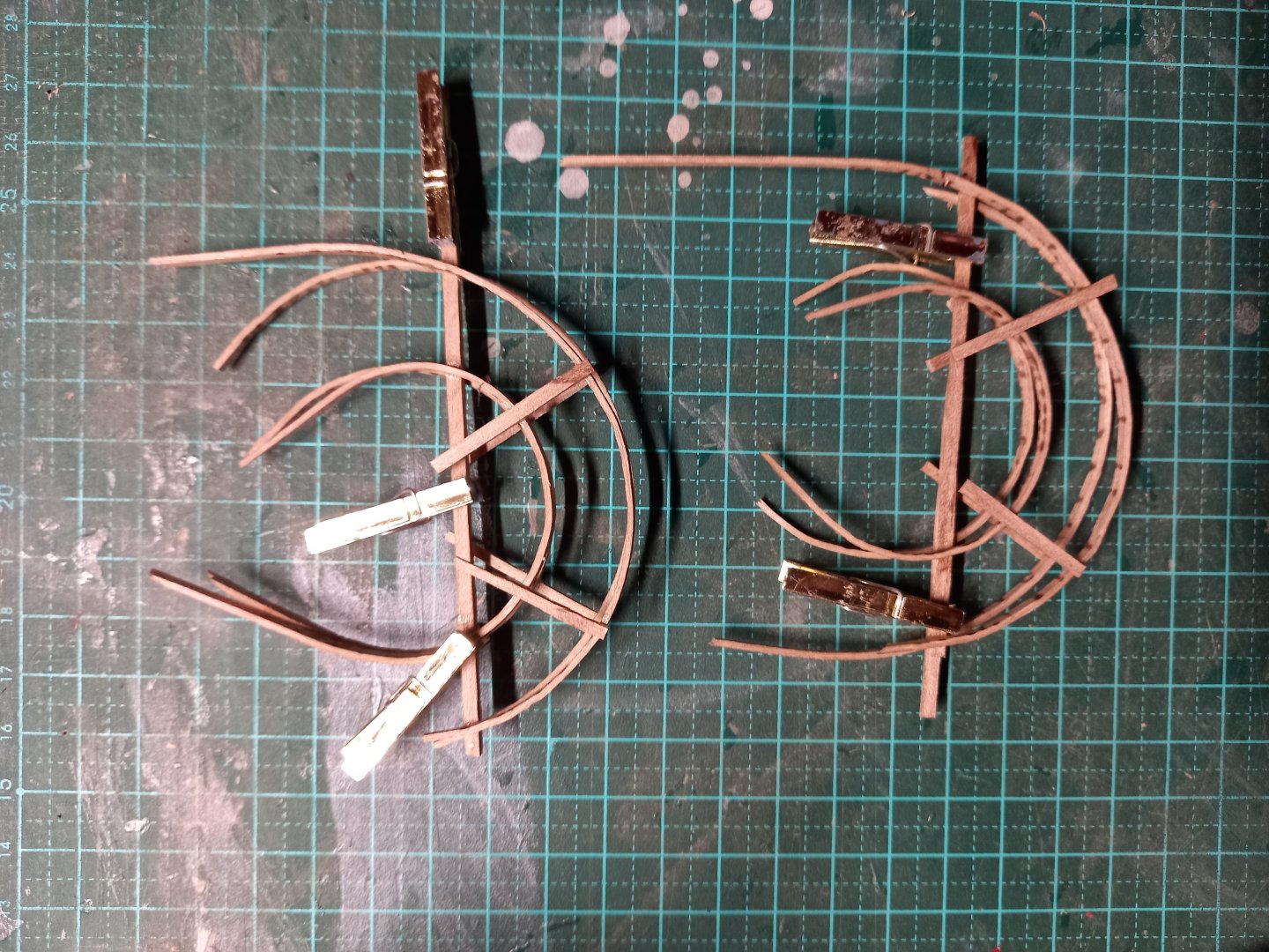
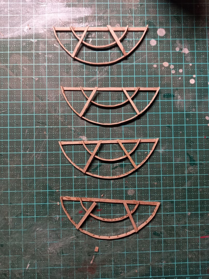
I've (finally) completed the buttock lines, and have amended the body sections to align with them. I'm hoping that will all work when it comes to making them. Last time I did it by eye (with the Great Harry it was completely wrong. We'll see if this works better. Steven
-
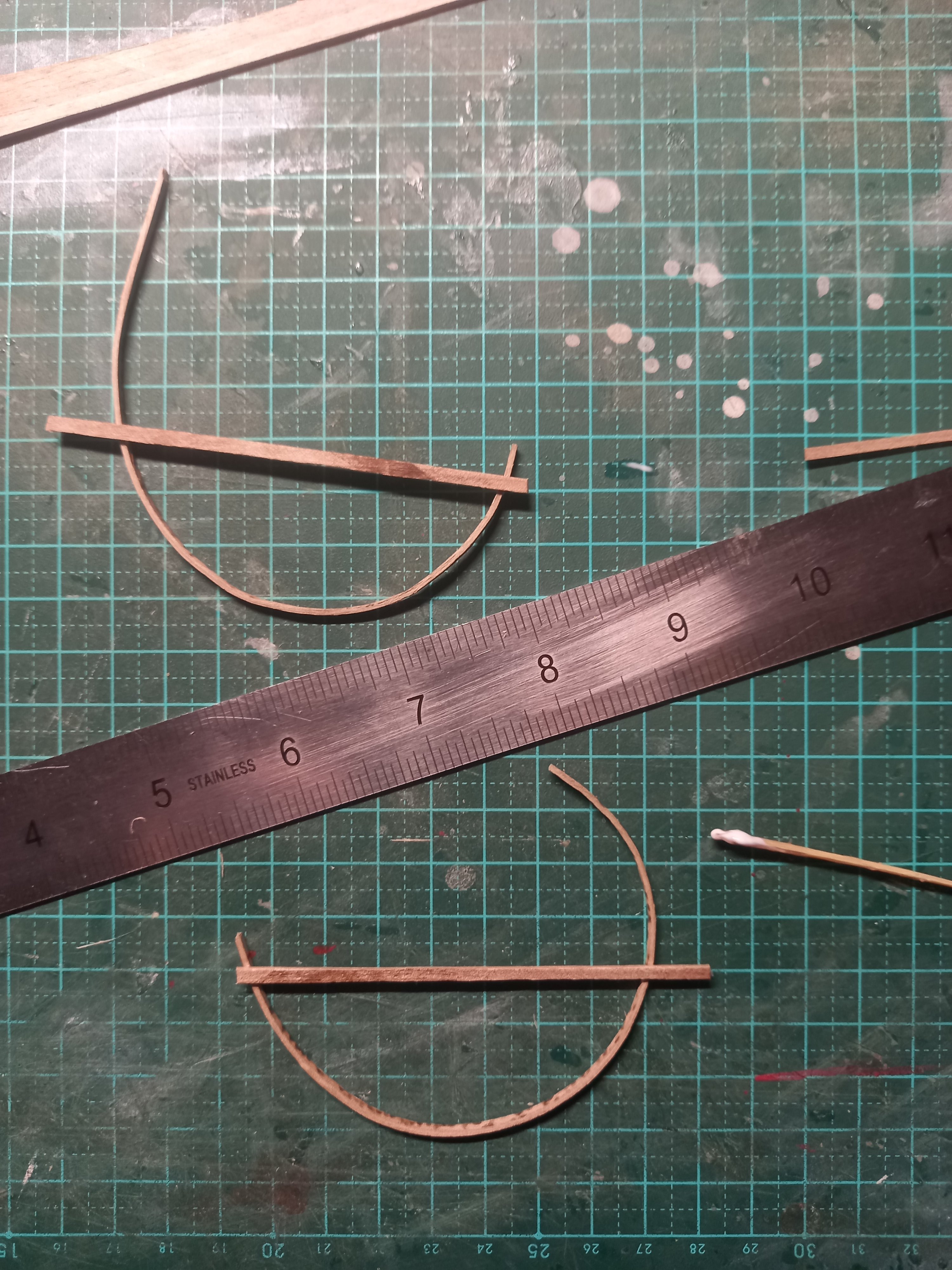
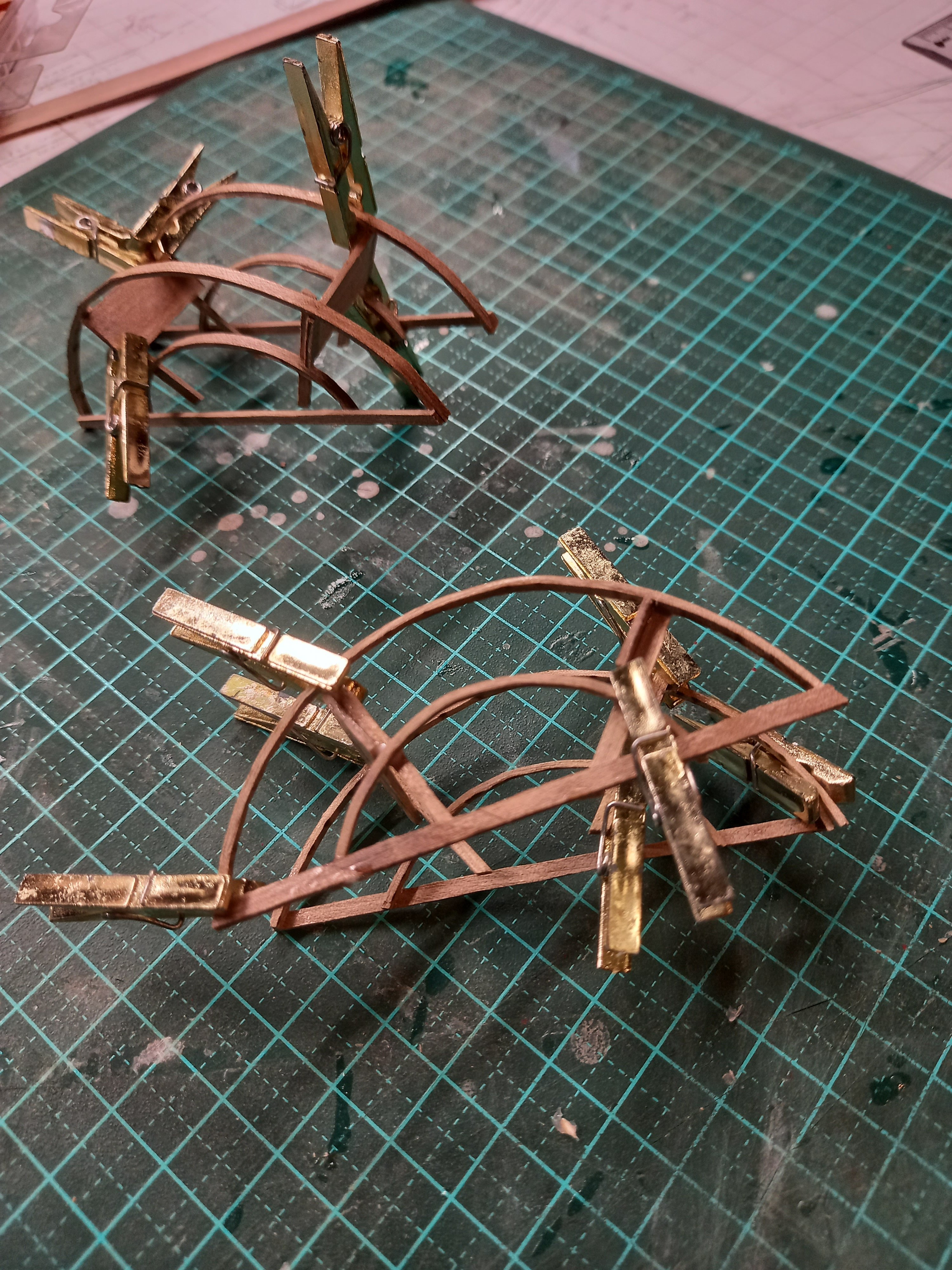
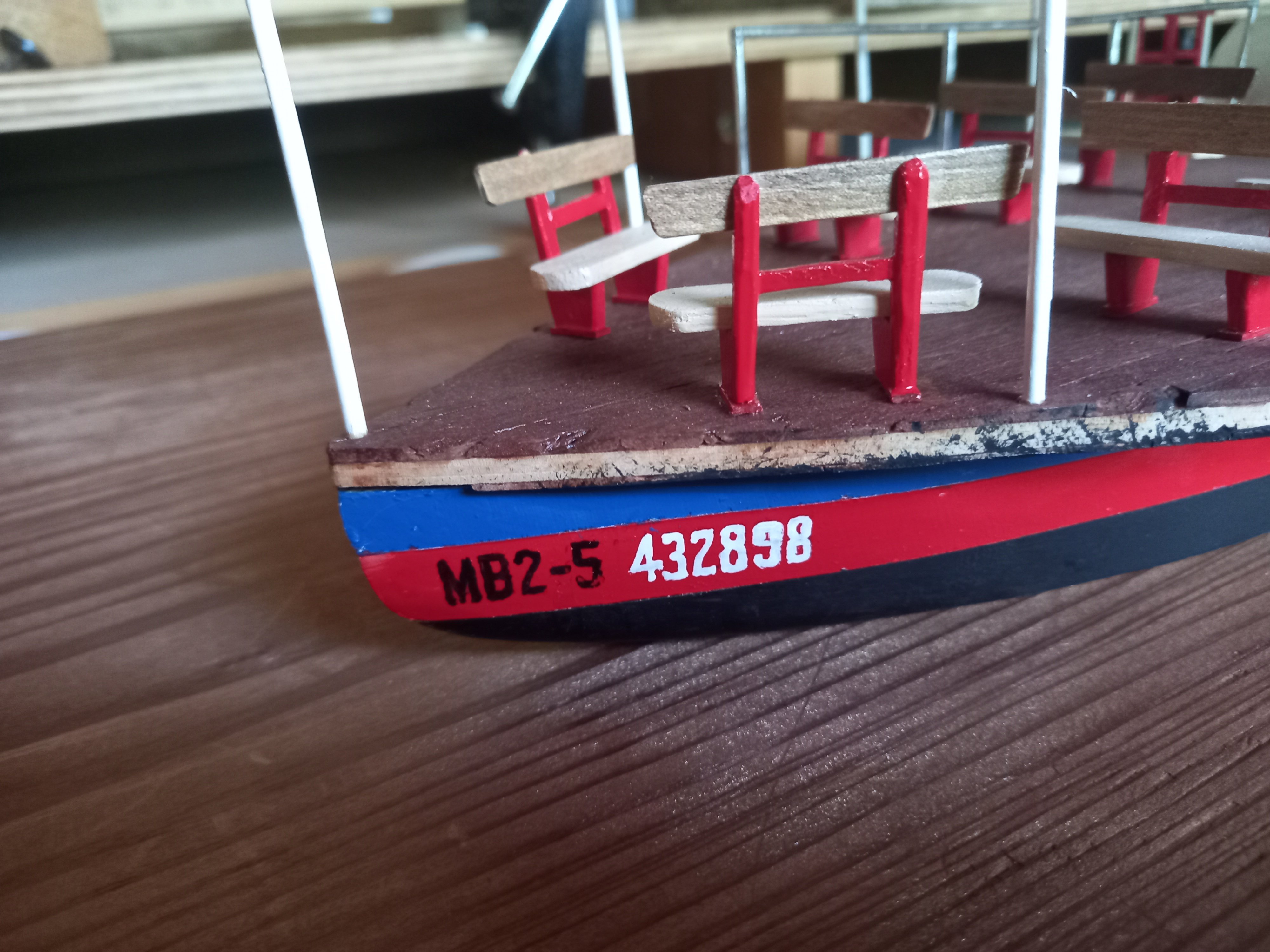
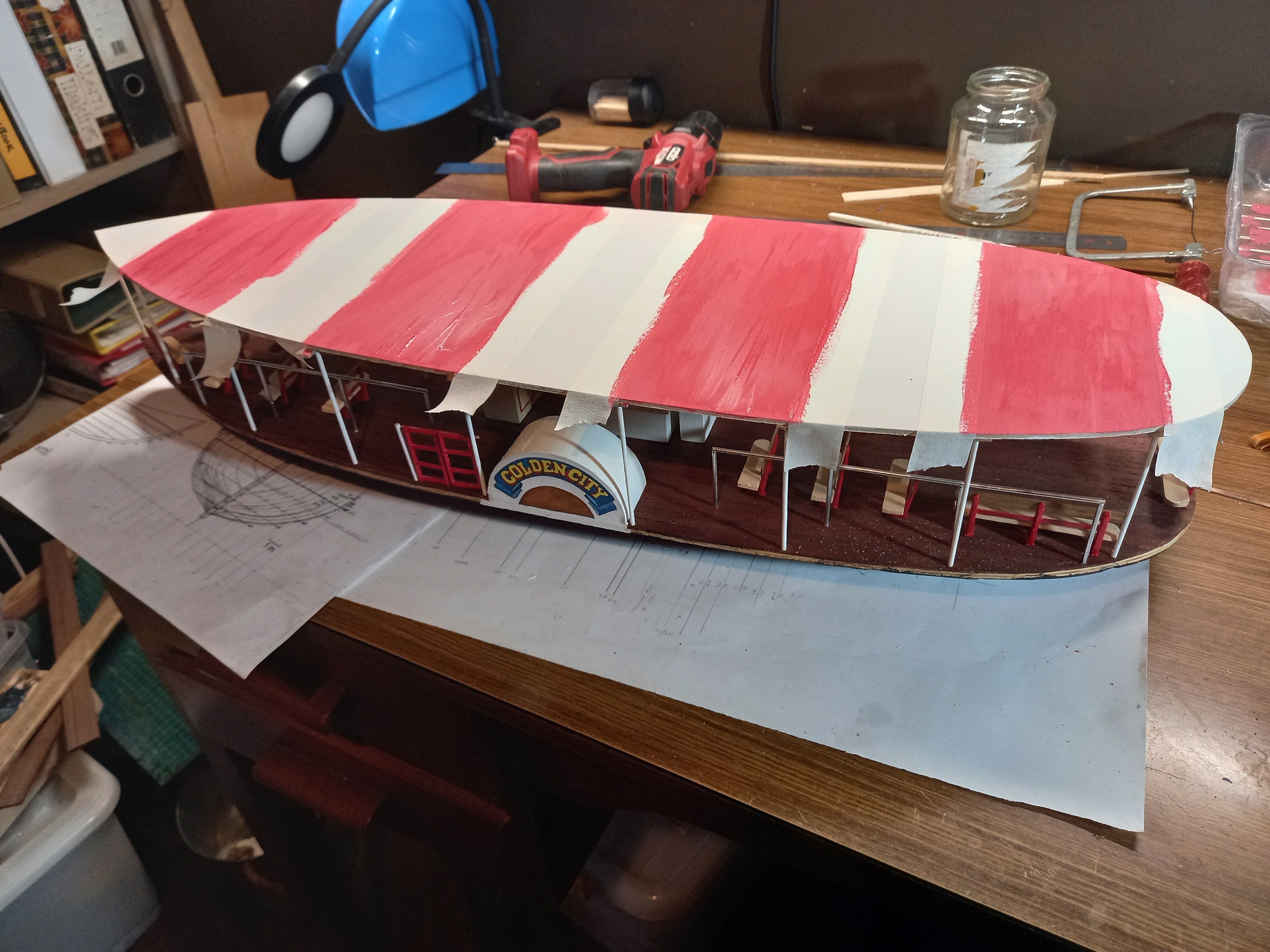
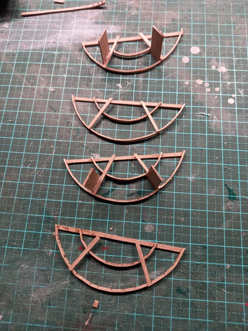
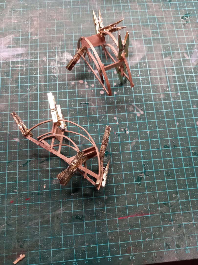
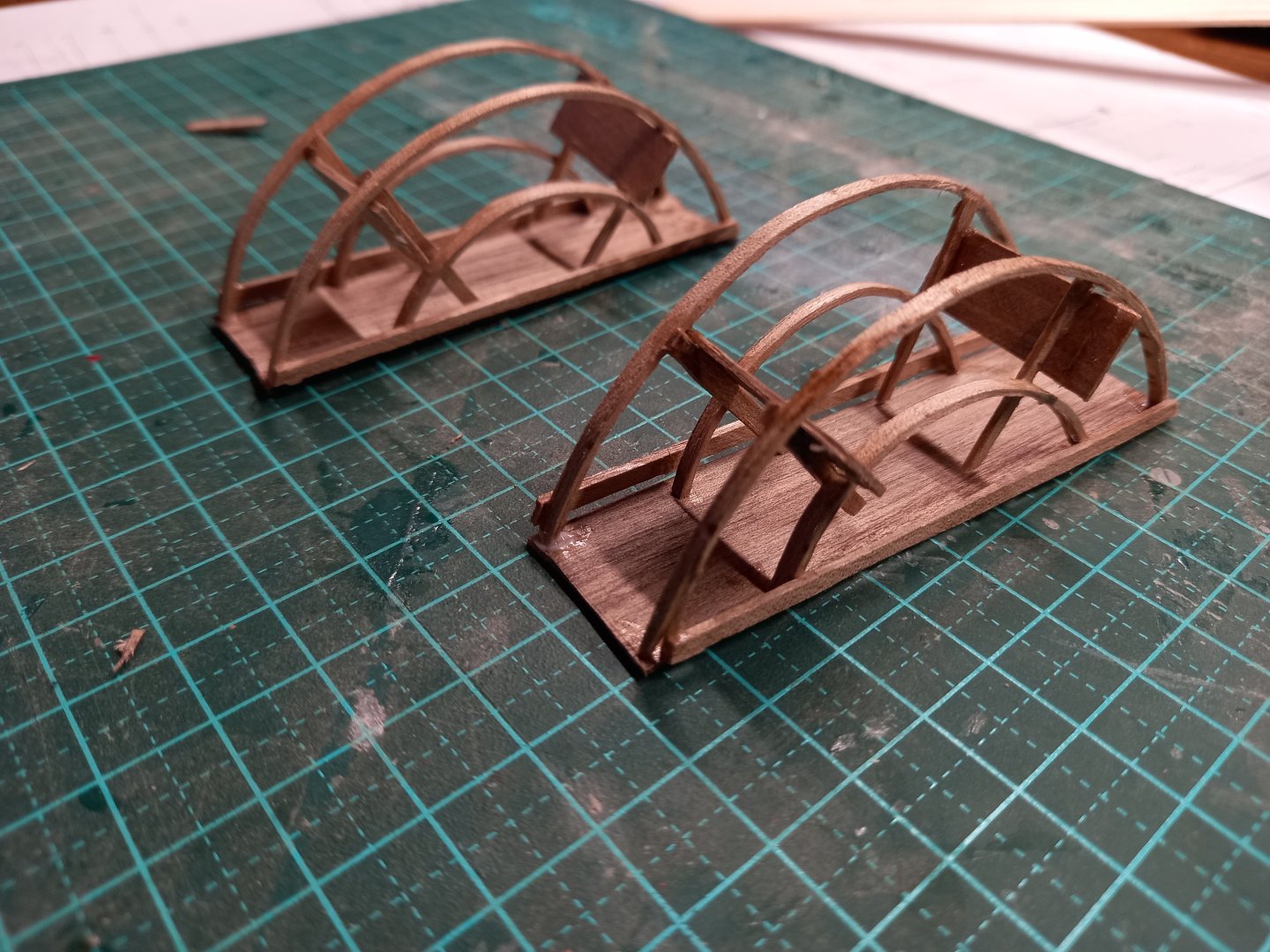
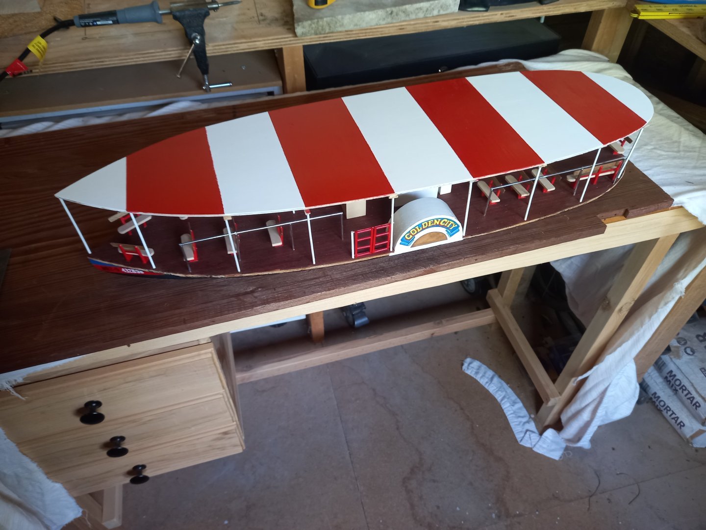
I've finished painting the awning. Still have to put the wavy fringe along the edge - not sure how I'm going to do that - paper? Card? Thin aluminium sheet? And here are the paddlewheels, as promised. I used my usual technique to make them - wet the wood and 'roll' it around a (cheap and nasty) soldering iron. Note that I've only made a segment of each, because the rest of the wheel is supposed to be hidden by the housing attached to the hull. Lining up pairs of "wheels" with each other so they would all be nice and square. Didn't really work all that well . . . And trimming them to remove excess. Adding the paddles. Putting the two halves together. It took quite a while to get these acceptable - the tolerances are very strict, the construction is quite frail, and warps and mutates when you look at it, and it was hard to get everything square, particularly the paddles. I eventually put an extra panel at the bottom of each assembly (top, really, as they'll be turned up the other way) to give them rigidity and keep them square. Not perfect, but adequate. And removed the side pieces which had kept everything together up till then. And painted. And here are the registration numbers on the bow, done with a fine watercolour paintbrush. A little wavery, but overall not too shabby considering the difficulties. Steven


- 110 replies
-
- 7
-
-

-
- Paddlewheeler
- Ballarat
- (and 3 more)
-
That's coming together well, Doug. Good work on the placement of the guns, the formation of the forecastle. For the full forecastle are you going to make a preliminary cardboard replica (as per the highly esteemed wireless-type Goon Show) to see how it looks before you cut wood? Steven
-
Remains of 500 year-old shipwreck: Dated 2019
Louie da fly replied to Allegheny's topic in Nautical/Naval History
Yes. I'm amazed what they can reconstruct sometimes with the scattered remains they are able to recover. Steven -
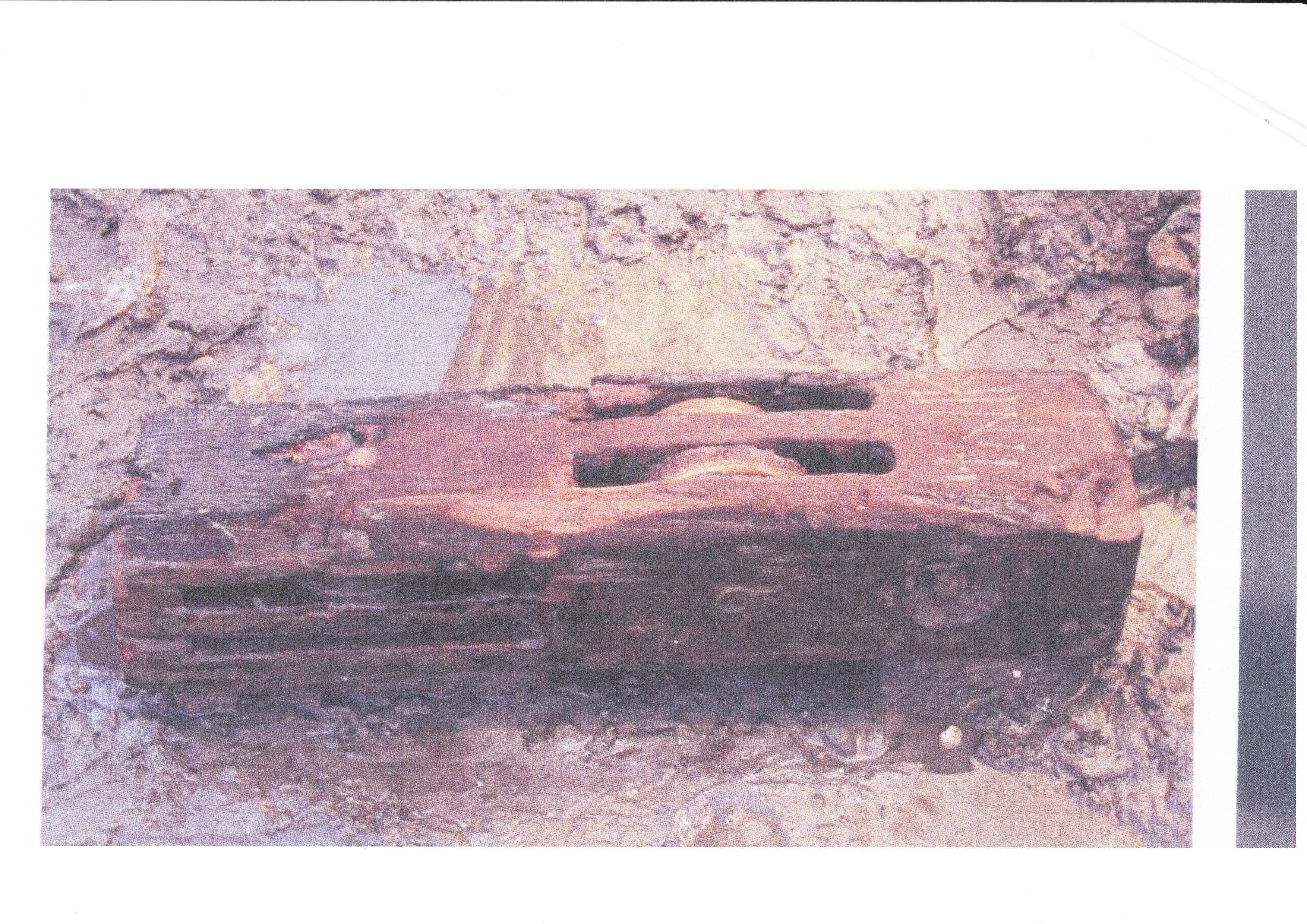
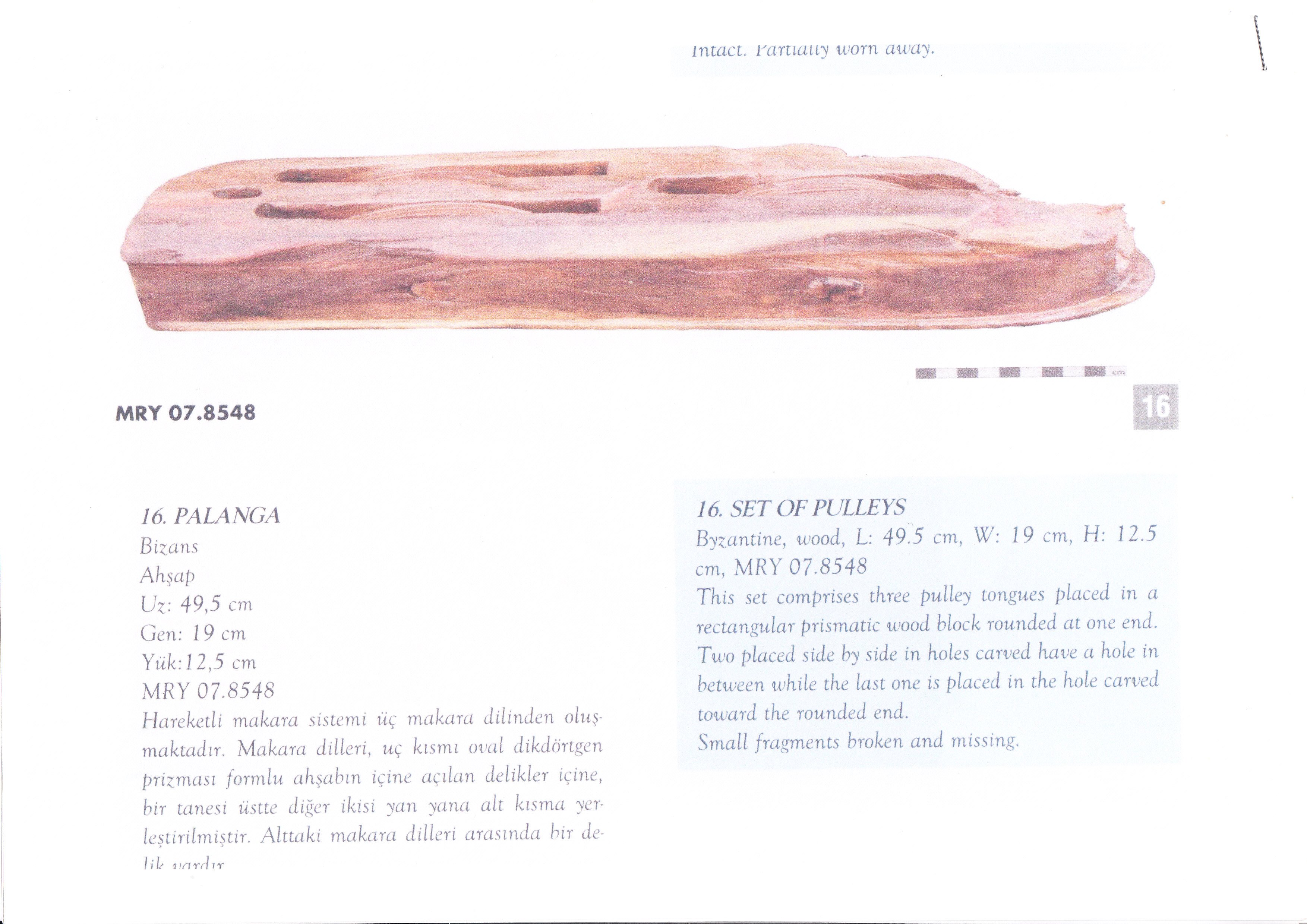
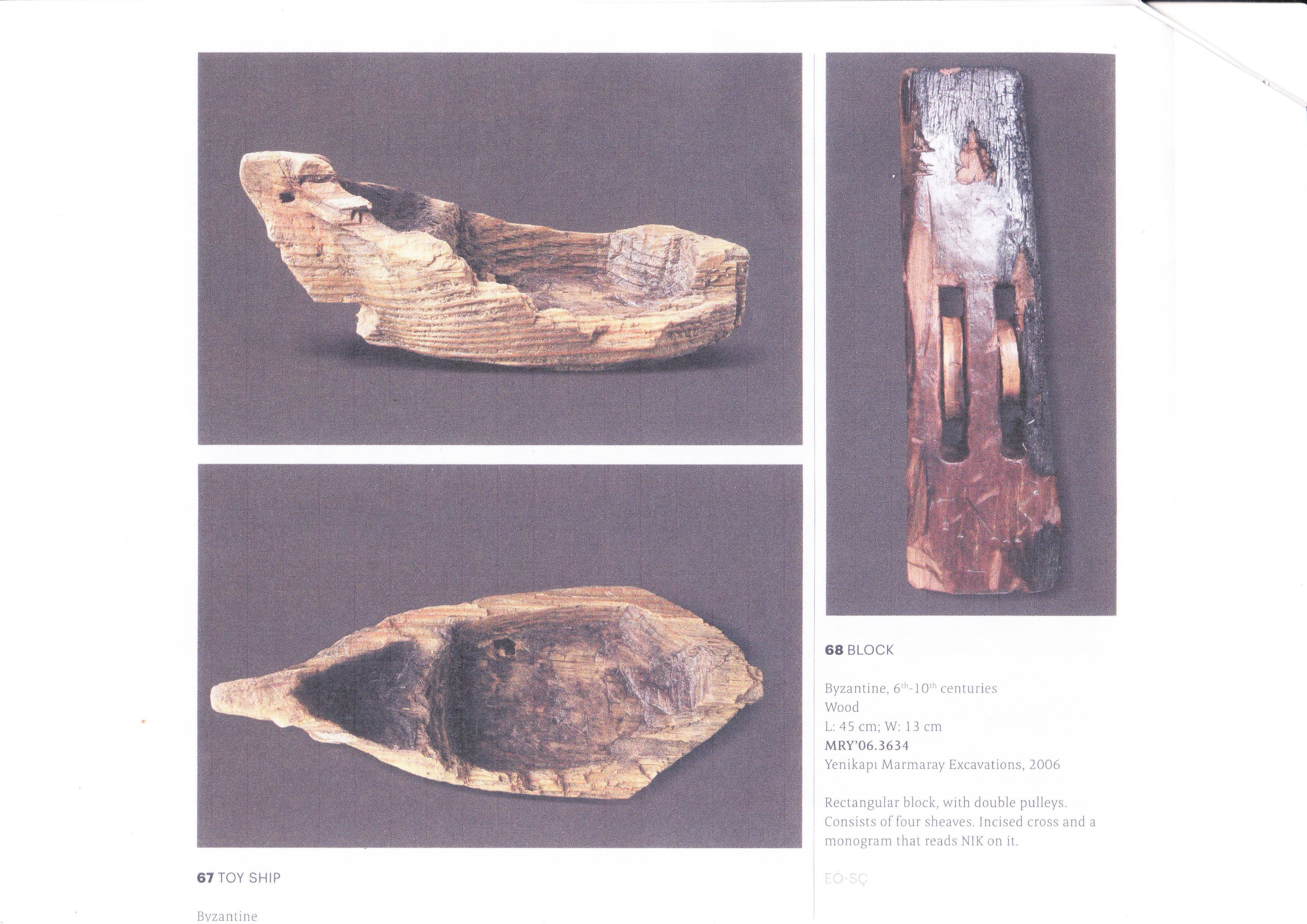
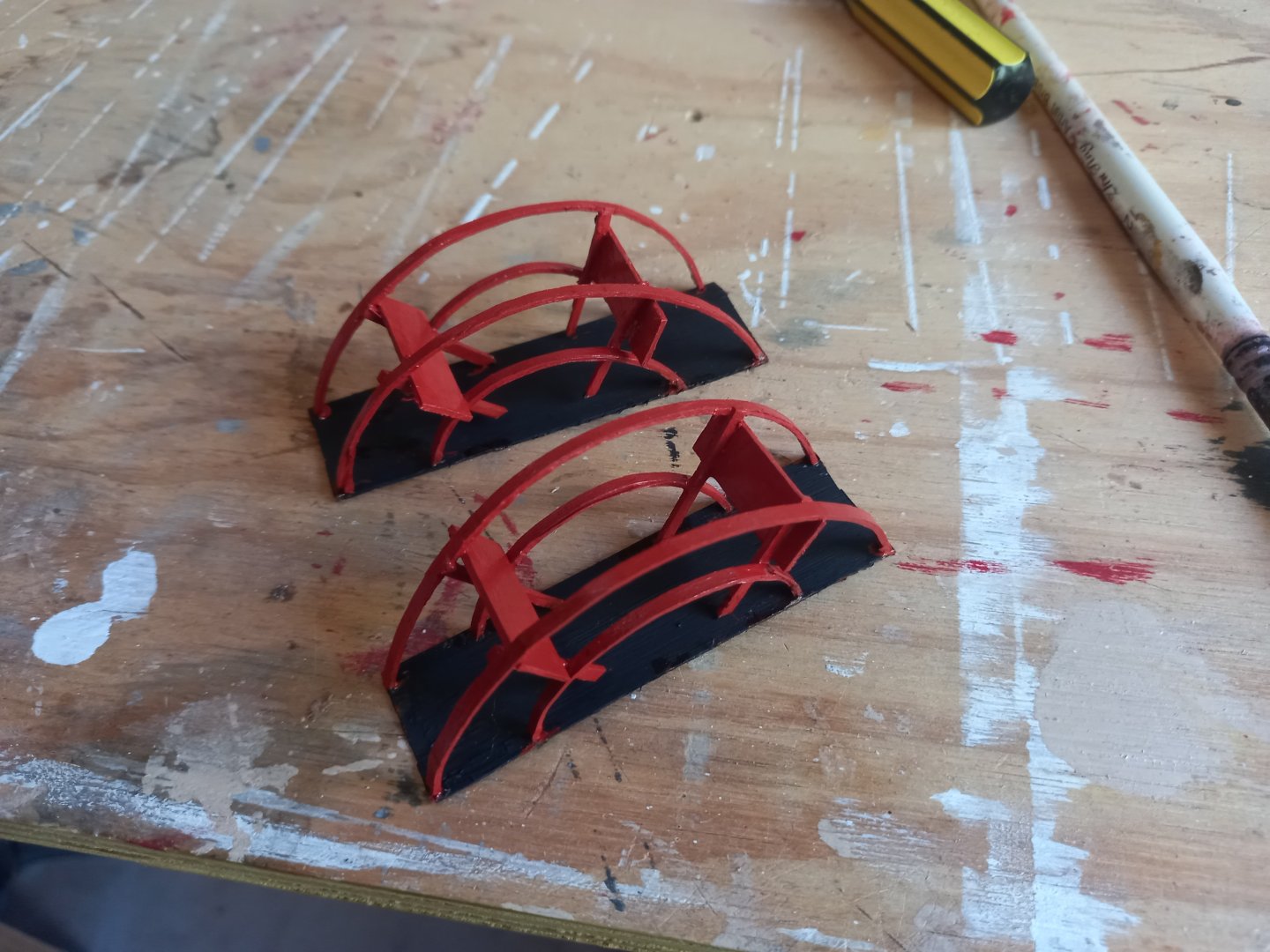
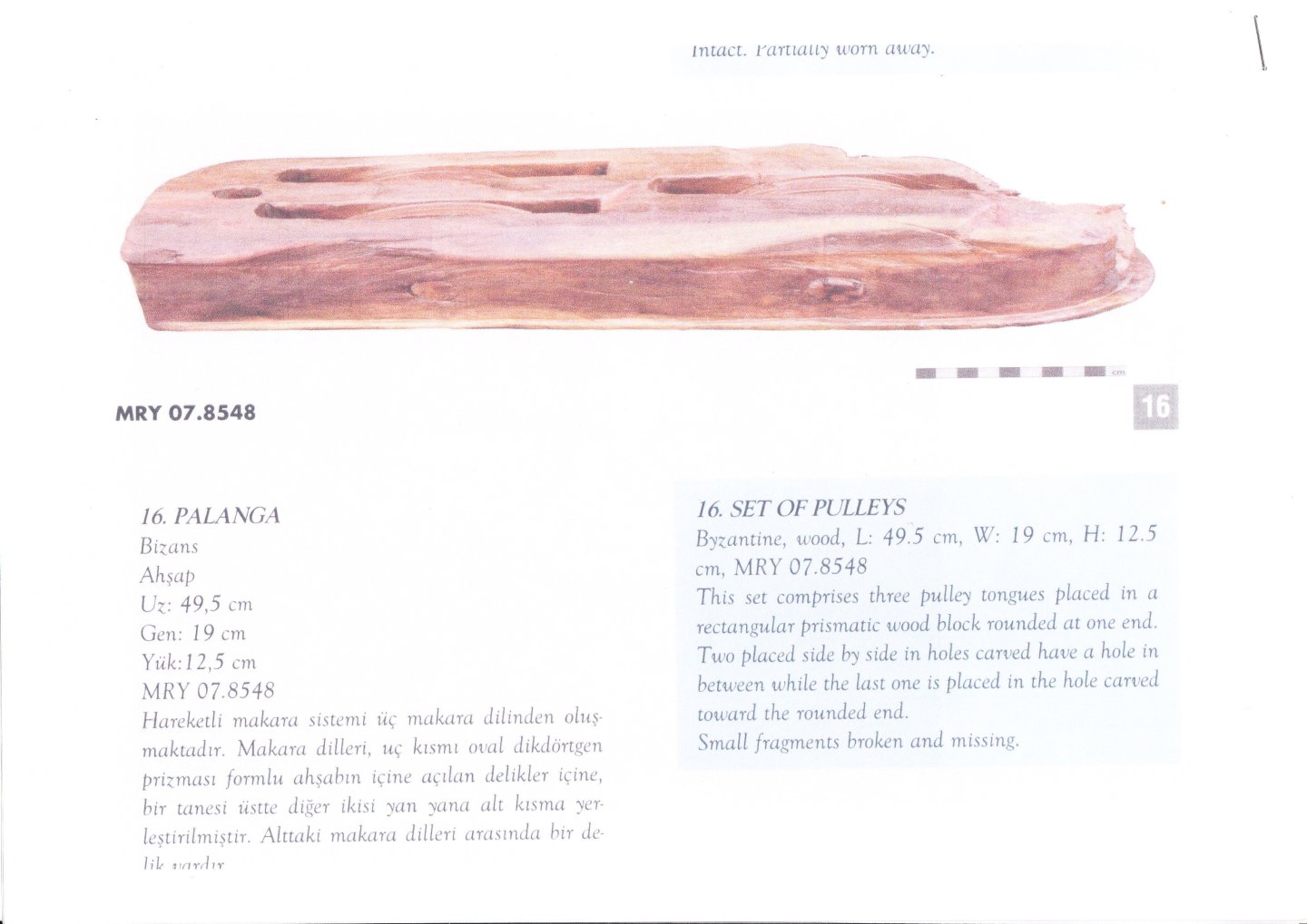
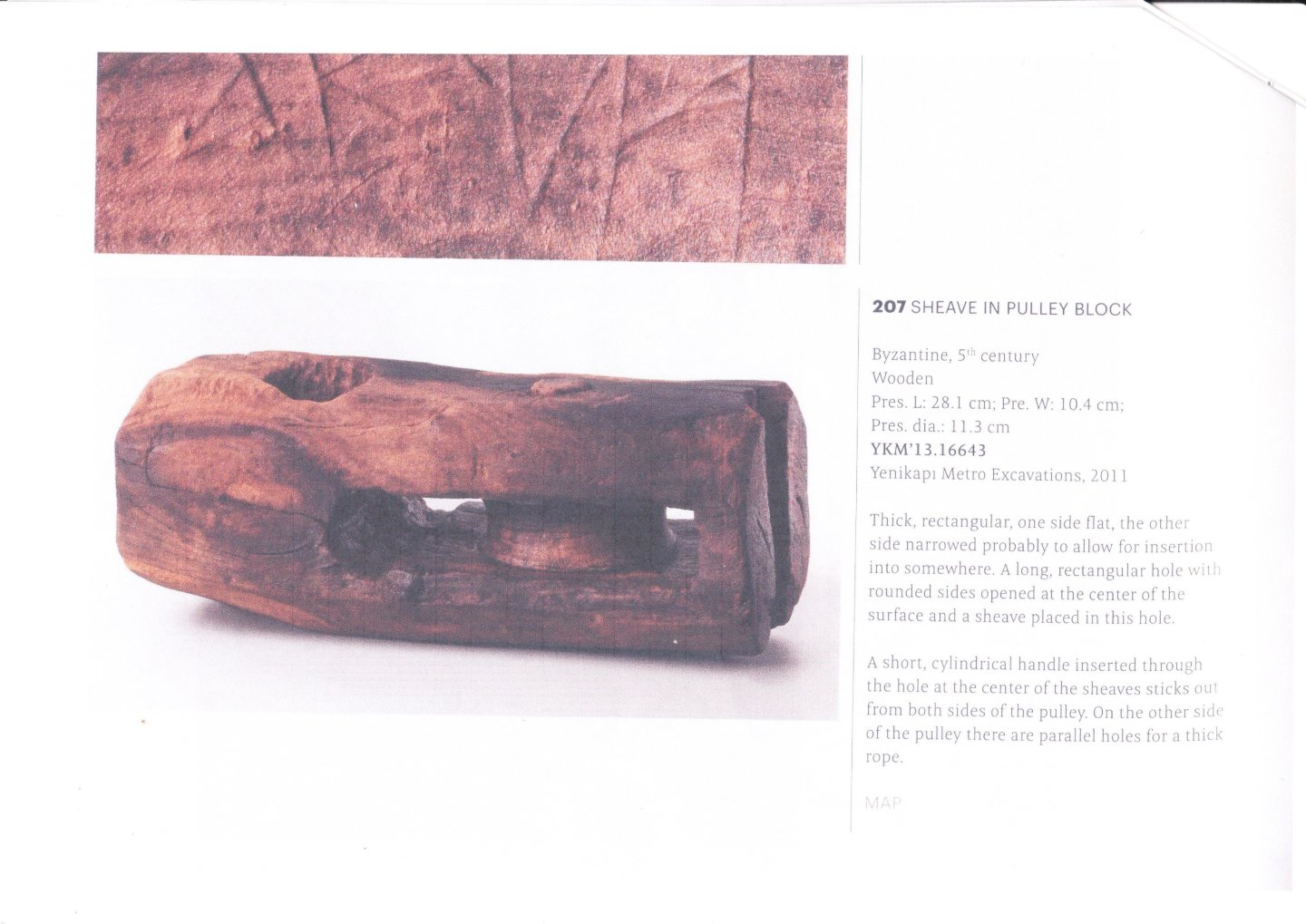
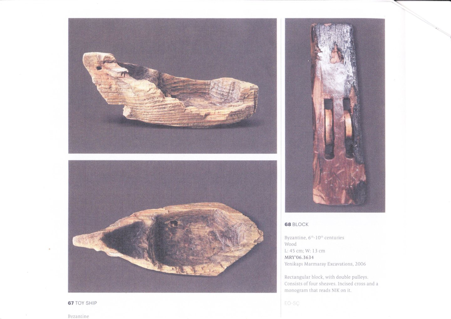
That's beautiful work, Richard. One small point regarding the blocks - the early ones I'm familiar with (admittedly mediaeval rather than ancient) seem generally to be rectangular rather than round. Some examples: Though there is one with a rounded end: It might be worthwhile to see if you can find surviving examples from your period to check against. Steven

-
Remains of 500 year-old shipwreck: Dated 2019
Louie da fly replied to Allegheny's topic in Nautical/Naval History
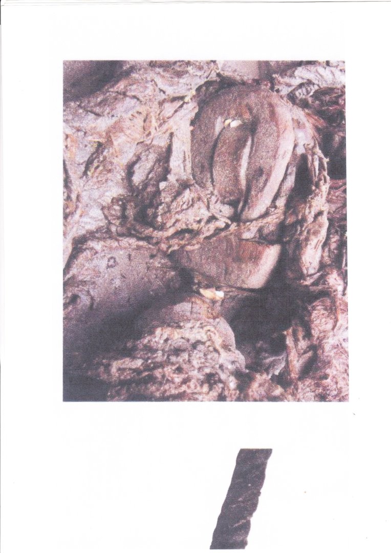
Thanks for this information. Every so often another wreck from this period comes to notice that I'd never heard of before. I've had a look at the site you linked, and it's fascinating. I'd love to see the archaeological reports on this one - in particular the kind of information that relates to modelling - the 'lines' of the ship, the equipment found on board, the masts etc. It's a shame nothing else seems to have happened about the Okänt Skepp, but unfortunately these things happen - if it's not Covid then it's lack of funding or some other thing. I'm still hoping there's eventually enough money to see if the forecastle of the Mary Rose can be located. That would be a real find! Steven -
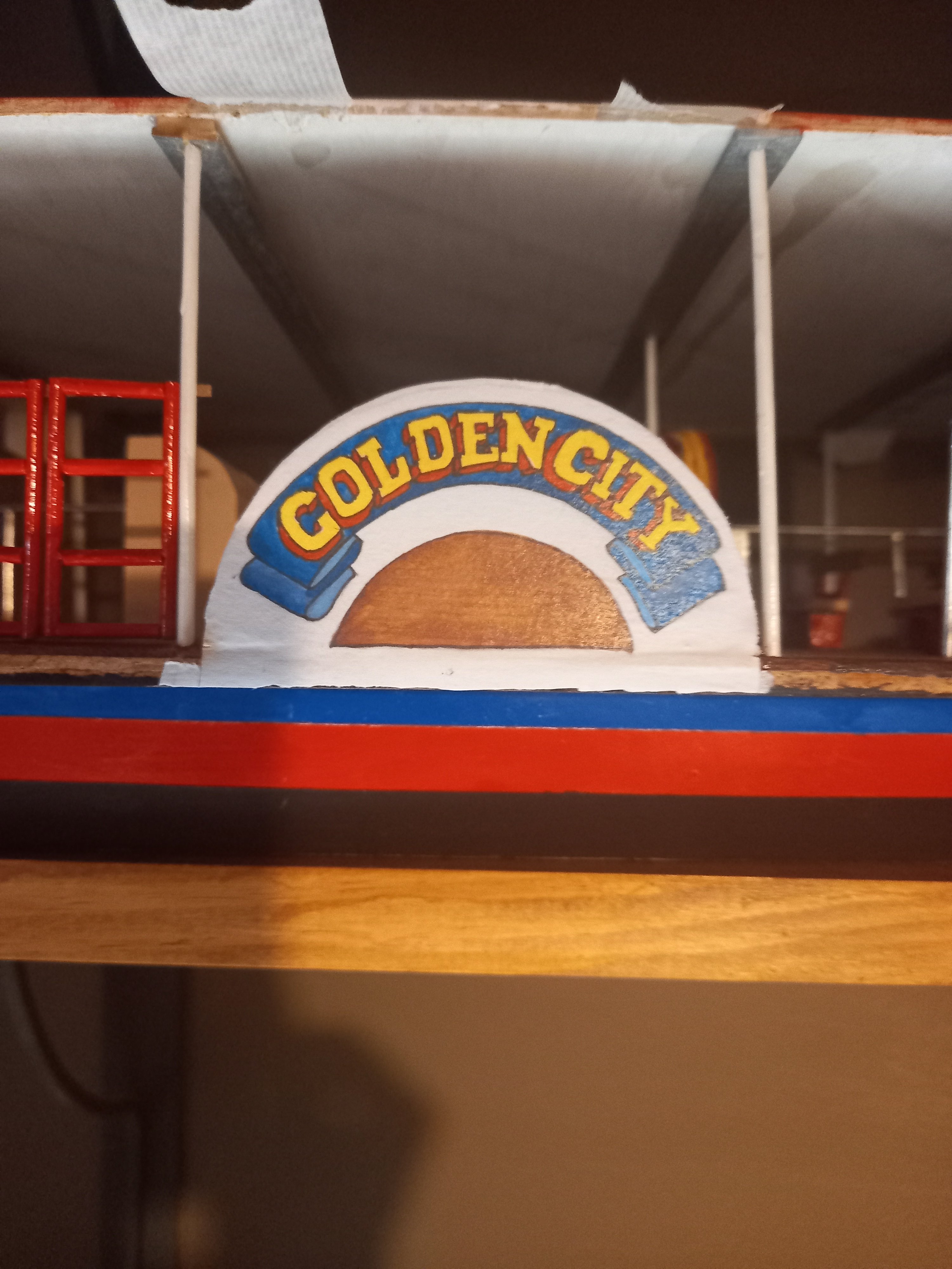
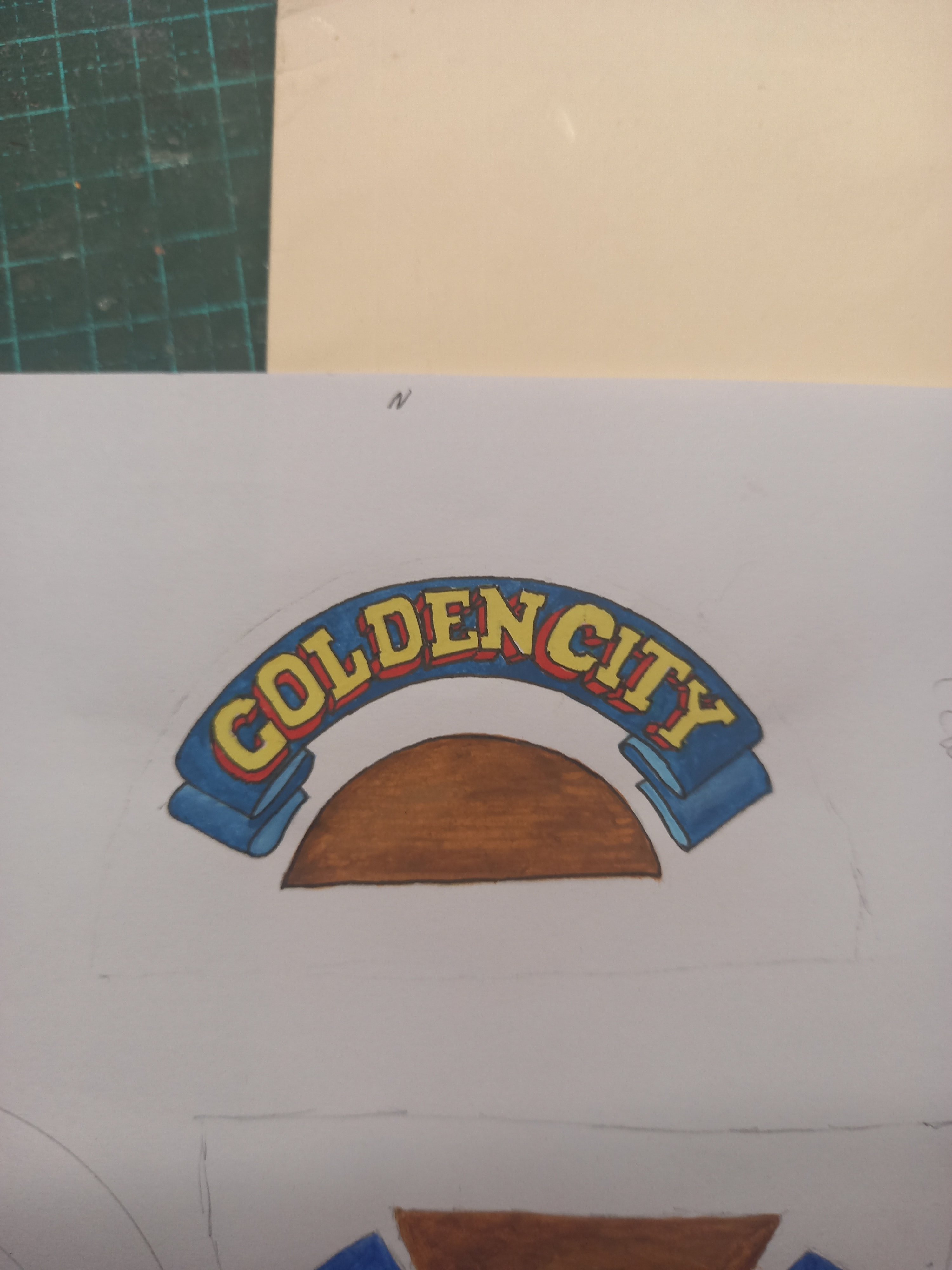
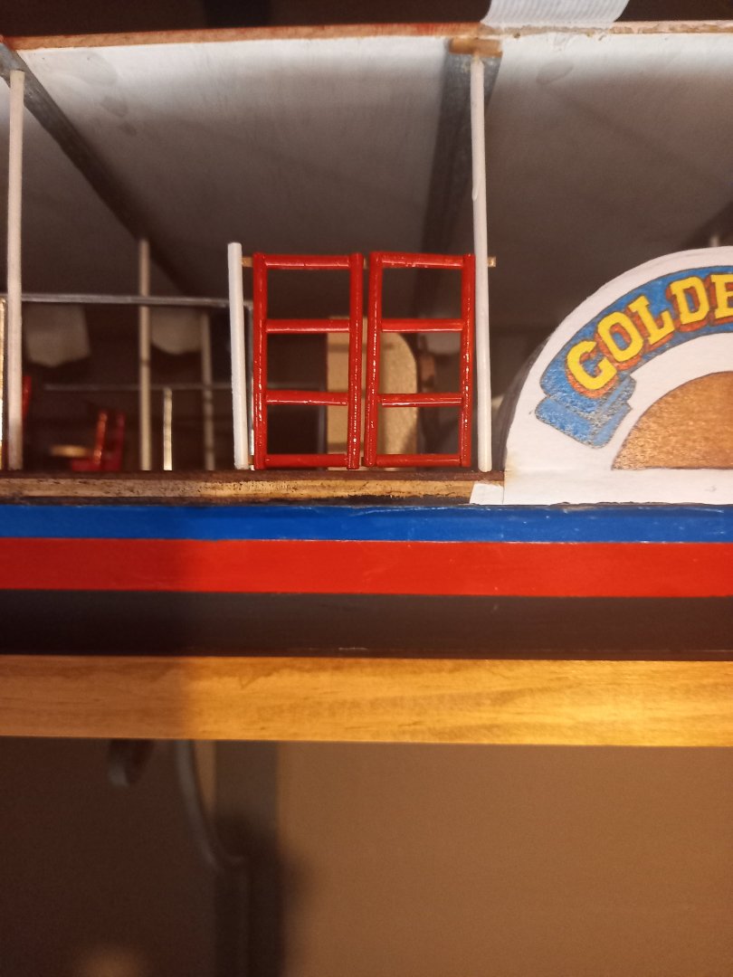
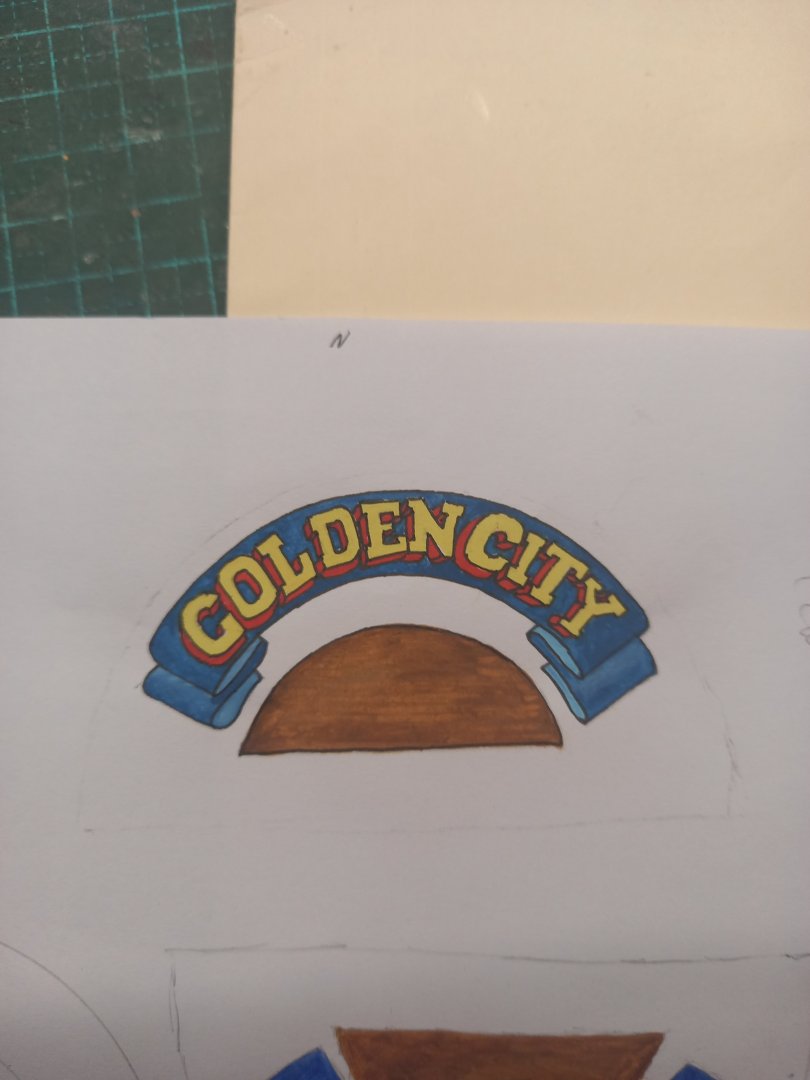
A small update. First, I hadn't mentioned how I'd done the logo on the paddlewheel housing. I had a photo of the vessel side-on, but the definition was pretty bad - certainly not good enough for the model. So I printed the photo out in colour, photocopied it up to the right size, then traced it onto white paper (up against a window in daytime), then re-did it as a new painting. Then colour photocopied it twice, so I had one for each side. And here it is on the model. Pretty happy with that. I've also made the little gates that stop people walking off into the water when she's under way. And I'm working on the painting of the awning roof. Red and white stripes. I've completed the white and just started on the red. First a coat of cheap acrylic - the colour is rather too pink, but it makes a basis and I'll be putting on extra coats with an enamel paint (Humbrol) that is the right colour. Steven


- 110 replies
-
- 12
-
-
-
- Paddlewheeler
- Ballarat
- (and 3 more)
-
Aaah, planking. So much fun. Your changes look good. And I think you're right to add the gunports to the transom. Not sure what the metal is they made the guns out of, but almost certainly not lead - that stuff's toxic and probably illegal to use in most countries - certainly would be avoided. But there are plenty of metals and alloys which can do the same job. Also IIRC lead shrinks in the mould when it's cast. These ones, for all their faults, don't look like they have done that. Yes, you can probably cast your own using these as 'blanks' to mould from. Steven
-
Nice work, Patrick. Steven
-
Timber is a very forgiving medium. You fixed the problem, and now you can move on. Steven
-
Oh, I know that. But somehow working out how to do them seems to have been more difficult than doing waterlines. As Pooh says, 'I am a bear of very little brain'. The thing is, working out the shapes of the frames without doing buttock lines ends up with them all the wrong shapes - something I found out doing the Great Harry repair. Steven
-
Yes, very nice neat work, and that walnut is a very pretty timber. Looking good. Steven
-
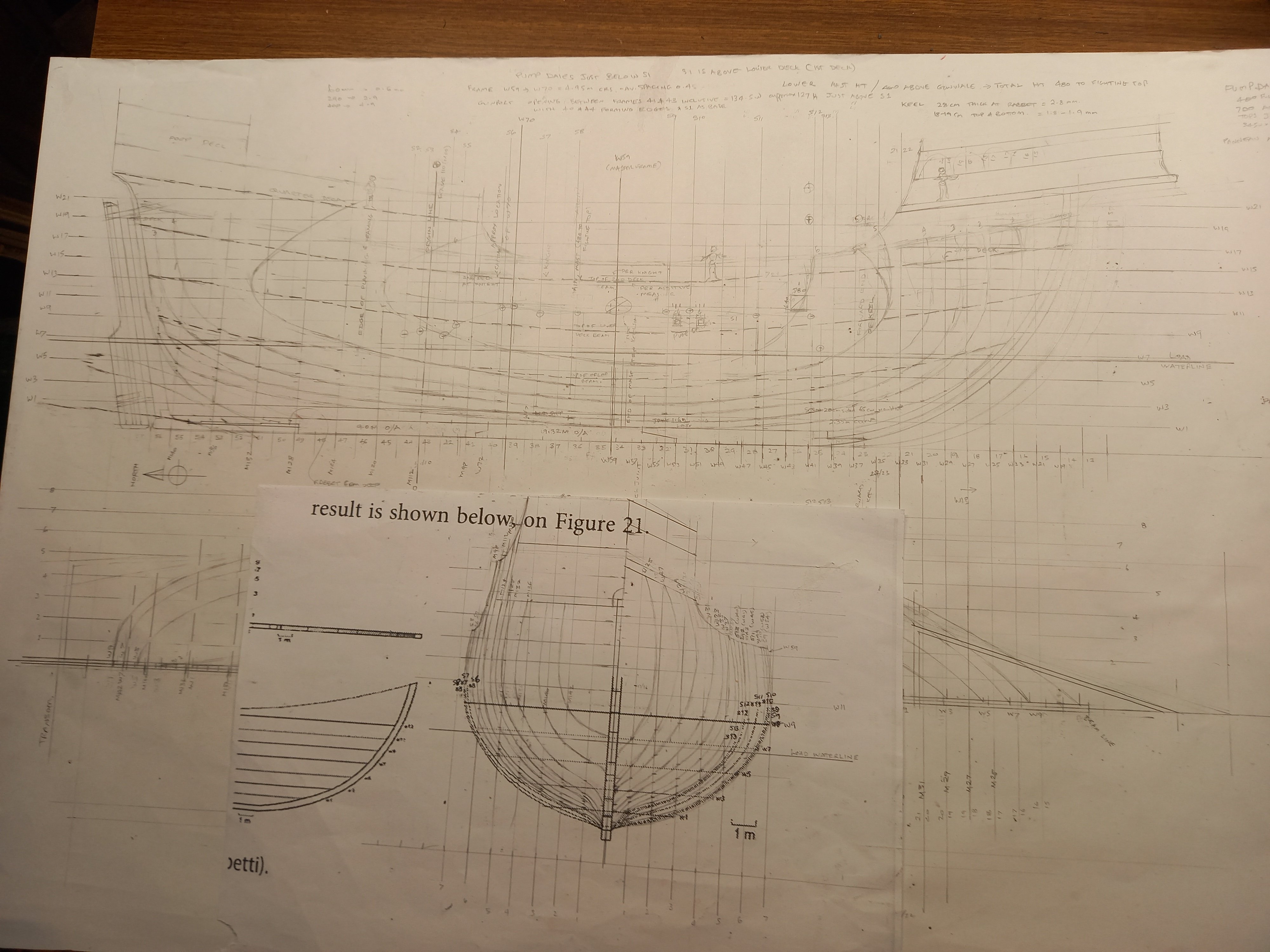
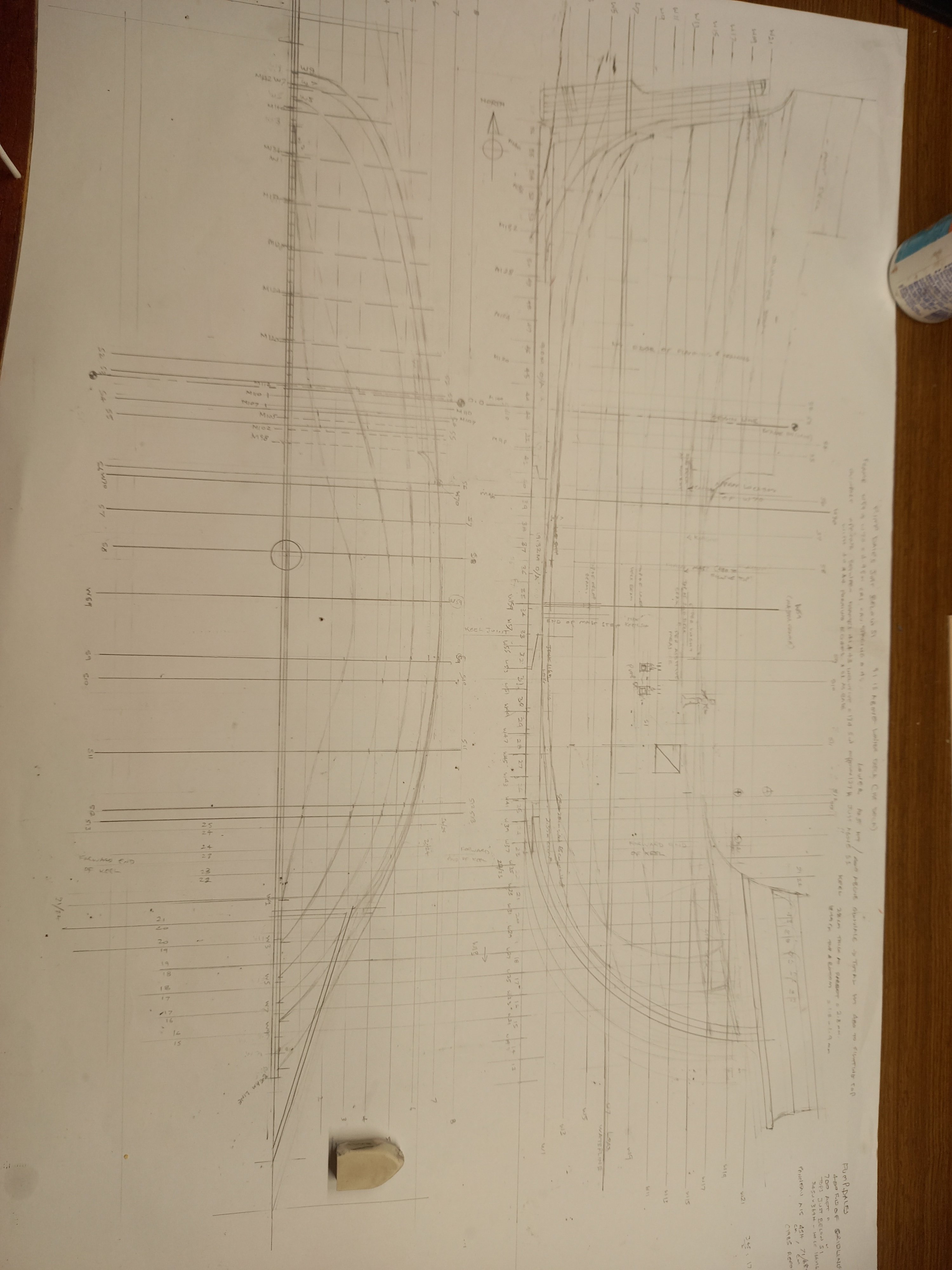
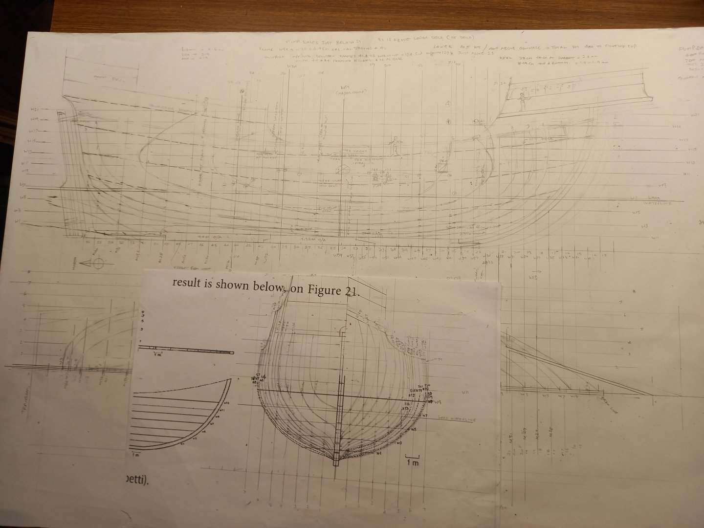
Still working on the buttock lines. Never done it before and I find myself getting confused as to how to do it. I have two in place now, several more to go - then I have to refer to them to adjust the shapes of the missing frames. A fair bit of adjusting from one thing to another to get everything to work together. And I've now drawn the (single known) gunport on the side view, having tied down its dimensions and location, bot vertically and horizontally. And the same for the pump dales. There were 12 guns found scattered around the ocean floor near the wreck, so presumably she had at least that many, six each side. I now have to work out if it's possible and practical to fit six gunports in the length of the ship. And check against the known planking to see if that contradicts what was found - in other words, are there uninterrupted runs of planking where I want to put gunports? I'm coming to realise that they must not have excavated the whole hull, but dug lateral trenches at intervals to get a variety of cross-sections and leave the rest covered up. So it's quite possible there's no record of uninterrupted runs of planking where I want to check - and even that there may well still be undiscovered gunports in the length of the hull. I suppose I need to check again at the source and see if that's correct. Sigh. Ça marche - pas vite, mais ça marche. (It moves - not fast, but it moves.) Steven
-
Me too. Looking forward to that stage of the build. Oh, and the rest of the build! Steven
-
Thanks Patrick and Druxey. Patrick, I'd seen the Mary Rose lines before, and in fact they'd been my main influence in drawing the frames near the bow that strange inward curving shape. It still will depend on how that converts into a real-world 3D shape, but I do believe I'm on the right track with it. Druxey, it's still in flux, but I think I've got most of the thing worked out. For example, I just changed the shape of the sweep of the hull at the break of the forecastle - it was too sudden, and looking at my pictures of carracks (particularly the Carpaccio ones, of course) I realised it needed changing. And I'm still thinking about the shape of the aftercastle - there's a certain amount of taper toward the stern, but how much? But I'm pretty happy with it all in general, and I'm just tying down the positions of frames with respect to the grid that was used in measuring the wreck. Basically, the frames seem to be about 500mm apart centre to centre, and using that, plus the known position of the master frame in relation to the grid, I can get a pretty good idea of where all the rest of them are, and relate that to the keel. And I also have a pretty good idea of the location of the mainmast, as the archaeological report notes the location of the fore end of the mast-step assembly. So from that I can locate the main knight and then the capstan. I've figured out where the surviving gunport is (what a joy, finding a gunport!) and its dimensions. She seems to have had 12 guns - welded rods with reinforcing rings. So that's six each side. And I have the locations of the guns in the wreck, so I can at least to a certain degree, get an idea of where they would have fallen from when the wreck disintegrated, and thus where the rest of the gunports might have been. I do enjoy the research, but this is the most mind-melting job I've ever had to do in ship-modelling. It's just a matter of sticking with it until I'm happy that I can't improve on it any further. Steven
-
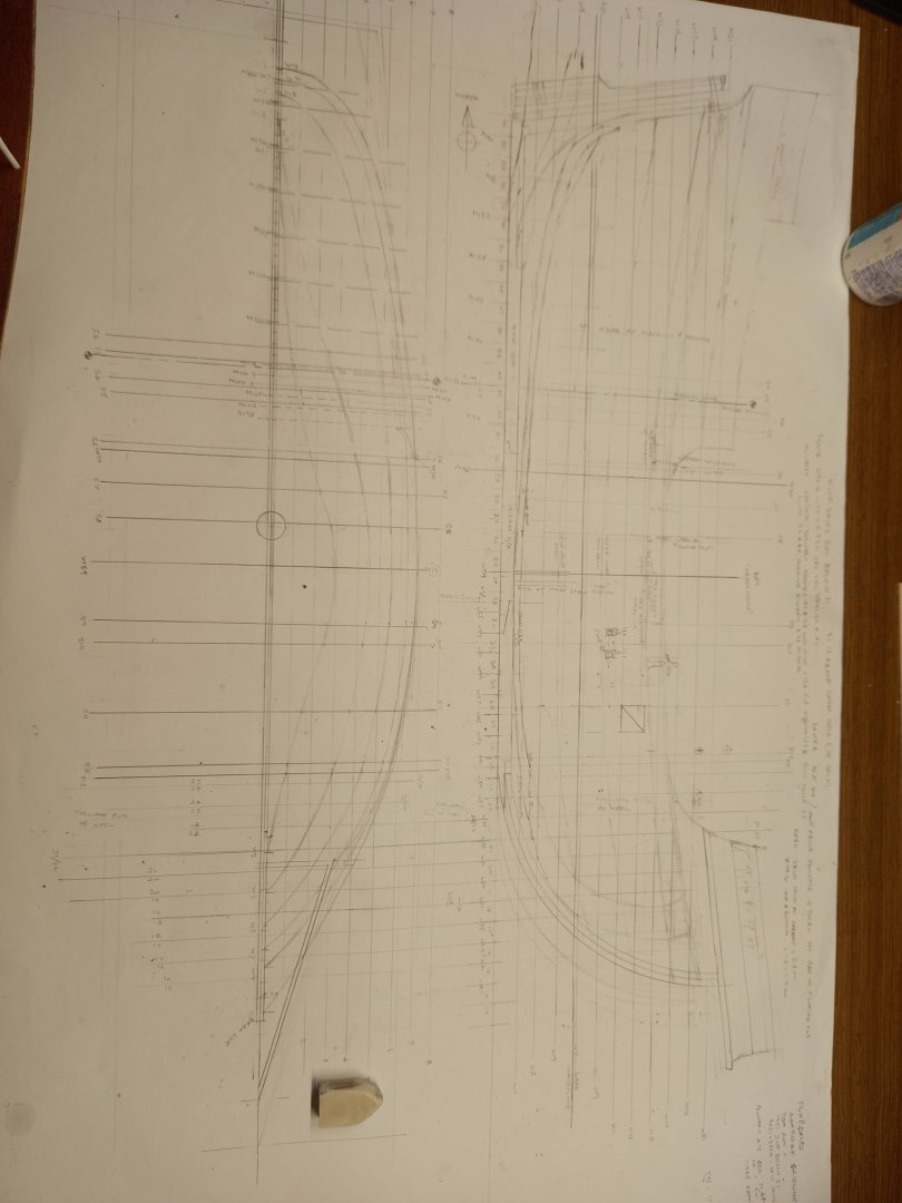
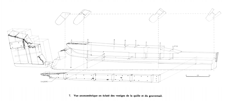
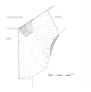
Yes, carracks were nowhere near as tubby as people seem to believe. This one appears to be more than usually slender. And the garboard was made out of half a tree trunk carved to shape. Near the stern, its quite thin (see the four cross-sections of the keel above the side view), But as it goes forward it changes shape dramatically, to follow the widening of the hull while keeping enough thickness for structural strength. The titles translated: Varangue = floor timber, Quille = keel, Ribord = bottom plank Fascinating stuff. It's like figuring out a jigsaw puzzle. What the French call a Roman policier - a detective story. Steven
-
More research and fiddle; trying to work out what the French text really means, cross-checking things against each other to get everything sorted before I start cutting wood so I don't paint myself into a corner as I've done too many times in the past. I'm sure I won't be completely successful in that, but even that is part of the learning process. So I've now worked up a set of lines that I'm reasonably happy with. Subject to practical application in the real world. Still a bit uncertain about the configuration of the aftercastle and the frame shapes for the bow directly under the forecastle. But whatever, here it is. It doesn't fully agree with the lines shown in the latest academic paper, but that doesn't worry me all that much. I didn't like them. I still haven't worked up the buttock lines, and I suppose I really ought to, to check that the others all work. For me this is a real slog. I have to take frequent breaks and do something else, or my brain melts. But I've just sorted out the thickness of the keel and 4 cross sections of its after part, as well as (I hope) all the lengths of the 4 pieces of timber that make it up - plus I'm pretty happy with the configurations of both stempost and sternpost (neither of which were recovered). Which means I can - if I want - start making sawdust. I suppose I now have to screw up my courage and make a start. I'm using oak for as much of the structure - keel, frames etc - as possible, but I might run out before I'm finished. If so, I'll just have to proceed with another type of timber. Not to worry - it won't be visible anyway. Watch this space. Steven

-
Remains of 500 year-old shipwreck: Dated 2019
Louie da fly replied to Allegheny's topic in Nautical/Naval History
I came across this on the Facebook site Archaeology and Civilisations. Though the wreck is not specified, from the description it appears to refer to the same ship. Among the islands of the Stockholm archipelago, at a depth of 28 meters, in 2017 the wreck of a merchant ship dating back to the 16th century, probably Swedish made, destined for the transport of material was located and documented by the archaeologists of the National Maritime Museum. ferrous and in particular of Osmond iron, of which about thirty barrels have been found. Loads of this type of iron, produced mainly in the Scandinavian area and exported to Germany and Holland in the form of spheres obtained from the refining of crude iron in special furnaces, are known only in two other shipwrecks, always from the waters of the Baltic. The ship, in excellent conservation conditions like most of the wooden wrecks of the area, thanks to the particular conditions of salinity and temperature of the Baltic that protect hulls and superstructures from the destructive action of xylophagous and teredini, still has the mast in the position of navigation, is about 20 meters long and 7.5 wide, and is characterized by elements of naval carpentry halfway between medieval construction techniques and those of the modern age: a precious fossil guides, in short, an age of great transformations , able to tell with a remarkable level of detail the transport of raw and refined metals between Sweden and Finland around the middle of the sixteenth century. Despite the decision to keep the wreck's coordinates secret, however, the looters managed to locate the site, and in the course of repeated dives they stole pottery and significant artifacts protected for five centuries from the cold waters of the Baltic: this is what the underwater archaeologists involved in the study of the wreck, recently returned to explore the hull. "What happened was very sad: it was like tearing pages from a book; now we have the cover left, but we have lost the content forever", Jim Hansson, the archaeologist who has been coordinating operations on the site. The looting apparently went on for several months. By the way, the comment about missing artefacts is very apposite in archaeology. They are often the best means of determining an accurate dating for the wreck - particularly pottery which went through relatively rapid changes of fashion, and of course coins, which usually had the date on them. Having them stolen makes it very difficult. Steven