Thistle17
-
Posts
1,054 -
Joined
-
Last visited
Content Type
Profiles
Forums
Gallery
Events
Everything posted by Thistle17
-

Sherline mill and lathe questions
Thistle17 replied to Landlubber Mike's topic in Modeling tools and Workshop Equipment
Mike I made a base with 2 drawers in it that store the smaller accessories. I find that on a crowed bench I am always misplacing, bits, the key for the chuck etc. It is worth the effort. Of course it does not hold the larger items like the tilting table but does hold the vise. My base for the mill is 17 1/2 X 14 X 3 1/2. The base has 4 rubber feet. I have yet to work out a good system for all the cables as you can see. Joe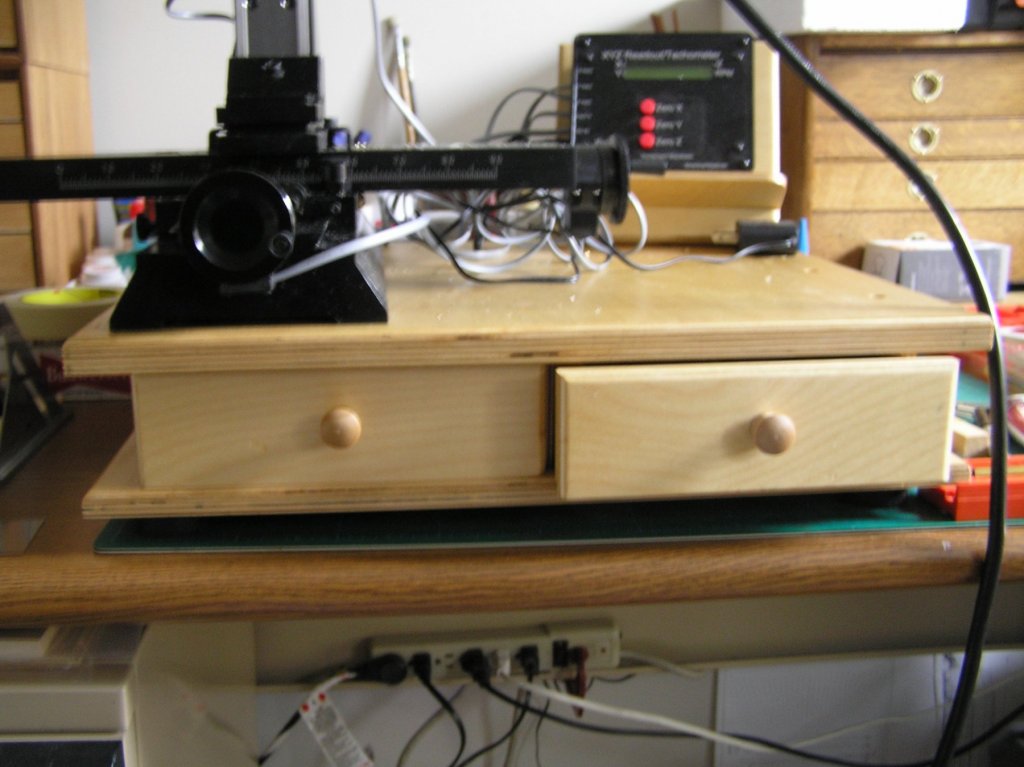
-
Atlantis by Thistle17 - FINISHED - Robbe
Thistle17 replied to Thistle17's topic in RC Kits & Scratch building
The wishbone connectivity to the fore mast has become problematical. I am conflicted by the many versions of the fisherman sail I review on line. I have seen the sail rigged with and without the wishbone element. I have seen the wishbone attached to the (fore) mast and not attached. This is especially true when it is used as a boom replacement. Today I realized if I use the wishbone (it would be a lot simpler if I didn't) it has to pivot off the mast and has to have a mast attachment that will allow the sail to pass up and through the mast receiver. So now I have to attempt to come up with a form of mast yoke that answers both requirements. This is driving me a bit crazy. Here is a decent image of what I am troubled by.
-
Atlantis by Thistle17 - FINISHED - Robbe
Thistle17 replied to Thistle17's topic in RC Kits & Scratch building
I think I have finally gathered the rules of wishbone rigging. I wish to clarify that wishbone "rigs" can apply to booms or gaff rig configurations. The whole idea of a wishbone is that it stretches the sheet and remains taught with force applied downward for it's use in place of a boom. For a gaff it also forces the sheet to remain taught and upward driven. In this case it does apply extreme force to the trailing mast top. It also creates additional stresses on the rigging in a jibe. For the same square foot of sail it purportedly offers higher speed under light winds. It is loved by some and spurned by others. It also eliminates the weight of hauling a gaff to its position. As a result of a more focused search I have learned it is always fixed directly to the forward mast to which it is associated. The wishbone is tethered to the opposite mast with a down-haul line. It is or may be attached with an up-haul line (for trim) to the opposite mast. The sheet is hauled to it's position up thru the wishbone opening with a peak down-haul to the deck or mast. The apex of the inverted triangle sail is somehow tethered at the apex of the free end of the wishbone via another down-haul line I presume. On this later point I will not add a down haul lineto this apex, but will tie it off as in the manner intended for the RC version of the model. I think I finally understand at least the basics of this rig. Joe -
Atlantis by Thistle17 - FINISHED - Robbe
Thistle17 replied to Thistle17's topic in RC Kits & Scratch building
I am getting to think I am over thinking wishbone rigging. Here is a recently found picture that depicts the wishbone attached to the fore and main masts, not the sail as the model would have me implement. Now I have to decide whether to live with the model implementation or change it over. Hmmmm! Joe
-
Atlantis by Thistle17 - FINISHED - Robbe
Thistle17 replied to Thistle17's topic in RC Kits & Scratch building
I have to correct my previous statement regarding booms on stay sails. In searching the web last evening to get some idea how the wishbone was attached I ran across a ketch that had booms on both stay sails. My method to attach the booms will deviate somewhat from the parts supplied as they would not hold the booms in a fixed horizontal position in relation to the masts. A picture will be supplied. I also came across a description of the tethering of the wishbone on a real craft that does not reflect the method for the Atlantis. I will have to investigate a bit further. Joe -
Atlantis by Thistle17 - FINISHED - Robbe
Thistle17 replied to Thistle17's topic in RC Kits & Scratch building
May I say that this type of rig i.e. the wishbone, causes me to pause and wonder why anyone would choose this sail plan in the real world. It is certainly not a one person sailer and I perceive it could be big trouble if weather turns foul in a hurry. Having said that I have been ardently working the sails. I simulated the panel stitching with a #2 pencil and rule. The panel layout was defined on the sail plan and worked out reasonably well. Given that the sail material is a plastic, maybe even ABS film, with what appears as re-enforced fibers it was easy to layout the simulated stitching. A sharp #2 didn't work as well as a round point one. The sail gussets were applied and the sails were fitted with the simulated rivets at each apex. The rivets were actually eyelets that had to be peened over. I did so by using suitable punches and final flattening via vise jaw crimping. The holes for the eyelets were made with a home made punch (dowel with a machined piece of copper tubing in one end). The machining was a simple chamfering of the tubing business end to form a knife edge. It worked well. I am at the point of fitting all sails. I find converting to a static model with simulated hauling and tethering rigging is a bit in conflict with the original intent of the model. I do not wish to over state the issues but if you look at the picture on this page from 2/4 you will see that the sheets forward of the main and fore masts don't have booms. The model does and now I realize this is an artifact of the RC methodology of trimming them on a tack. The sheet ends can't "fly" on the RC version as the controls would have to be synchronized to haul in on one side and let out simultaneously on the other. So now I have to decide how to make them work with the static model as they just float at the sheet base and need some form of tethering to make them look convincing. Also I am trying to add working tackles to the sheet hauling works. Guess what; there are very few to be had out there at the moment. I forgot to mention the main boom I discovered was too short by about 5/8". I cut it to the diagram length but at no time did I measure the length of the main sail at its base against the plan boom length. I again used a piece of copper tubing and CA glued it into the existing boom and attached the extension. Now the sail tensioner works correctly. I am plodding on. Joe -
Jeff here is a suggestion that may help. Look on the The Nautical Research Guild web site under this sub text general listing. Hope this leads to a solution. Good luck. https://www.thenrg.org/links-and-sources-for-the-ship-modeler.php and right on this site under "someone looking to start a club in Palm beach". It is close to the bottom under Organization and Club News (parapharsed). I would have given you the direct link but it hung up my system for some reason. Joe
-
Dave that is great methodology and ingenuity you display. i just bought some turnbuckles from a supplier and while they fit the 1:20 scale model they still looked clunky. Your method would have been a better solution. Thank you for sharing. Joe
-
Hello Kristoffer welcome to this forum. I am far from an expert modeler, especially when I witness the beautiful work herein. I reflected on your comments and self critique and smiled. I too view my work in a critical light and am probably my worst critic. I think that is healthy in a way. Your mind's eye is already calibrated to a goal of further excellence and you will grow as each project goes by. Its a learning experience and the "chase" is part of the fun. Keep going you have the right mind set. Welcome to MSW. Joe
-
Atlantis by Thistle17 - FINISHED - Robbe
Thistle17 replied to Thistle17's topic in RC Kits & Scratch building
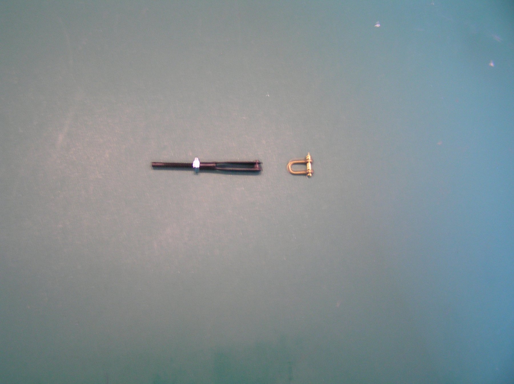
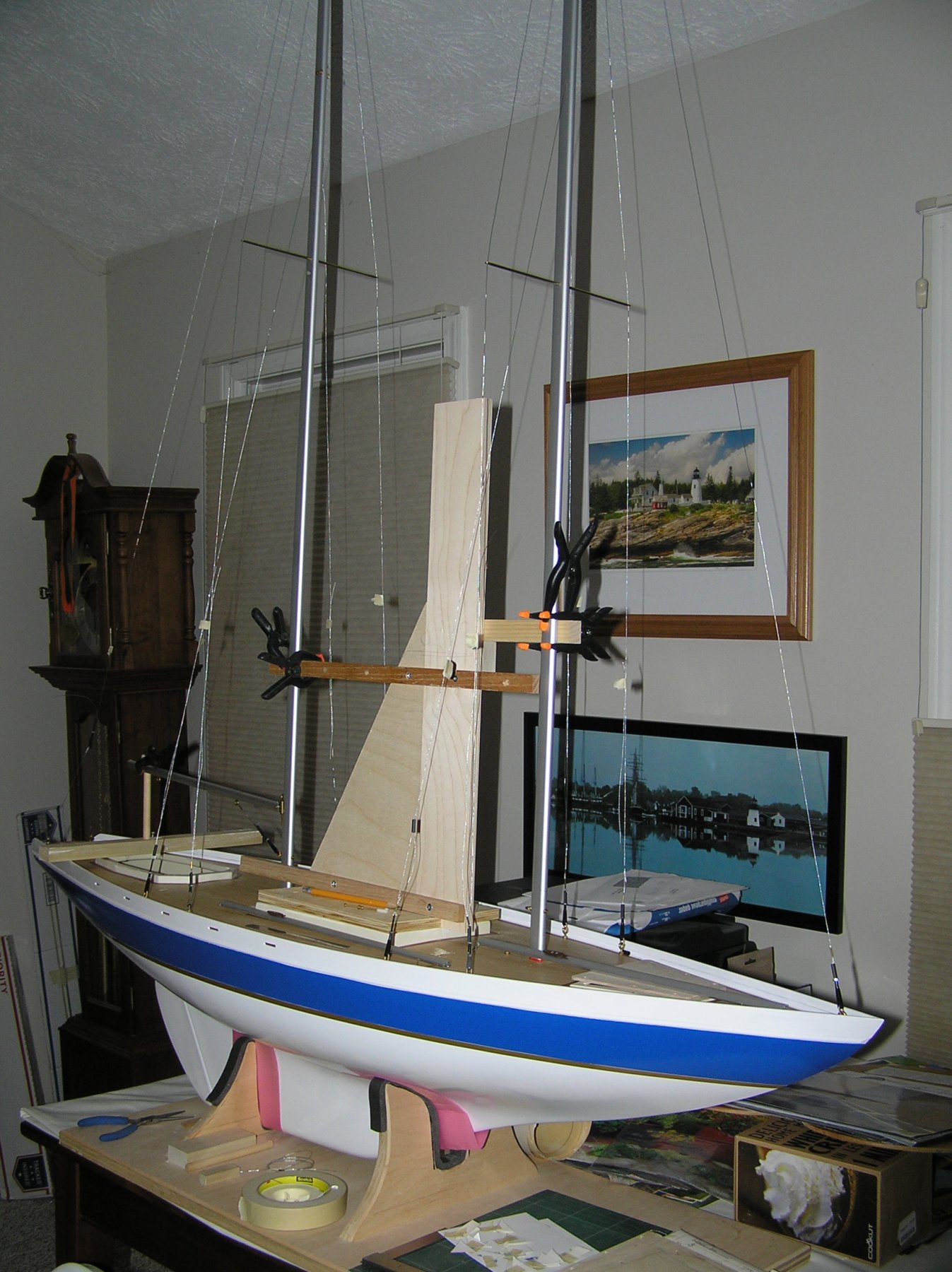
I have been spoiled by the high standards of today's instruction sets, especially those produced state side. I find that this model has caused me to retrench my work numerous times in part because of very poor instruction/guidance. I have rigged all stay and shrouds (but not soldered them or trimmed them) and have begun working the sails. They have required re-enforcement of the corners that are terminated as in real world sail making. Unfortunately the material provided was dirty and too small to use for all sails. Luckily I found material at a fabric shop that nearly matches the weight, color, texture and thickness of the kit sample. It is drapery liner. I have tried a number of adhesives to apply the cutouts to the sail but they peel off easily. I finally settled on DAP Contact Cement which can be applied with some precision. Once past this problem I began trying to fit the "Fisherman" sail and the Stay Sail between masts. I quickly observed that the sails do not fit neatly in between masts. Although the mast spacing is accurate (15 13/16 in apart) top to bottom the "Fisherman" has to be trimmed to dress nicely in between masts and the Stay Sail. To compound this the upper corner of this sail does not meet where main mast tethering is located. Luckily the combination of shackles and adjustable Du BRO fittings have saved me from an impending disaster. Pictured below are the shackle and Du BRO adjusters used. The second photo depicts the stage I am at. What is missing in the picture is the 4 foot step ladder I have to use to get to the mast tops!!!!!! Joe
-
We haven't posted in some time due to some setbacks. For one we had to rethink the use of Alaskan Cedar as its availability from our favored supplier isn't going to happen in time. We have reverted to basswood and will deal with the finish problems that will arise. Secondly weather and member availability have hampered work time. We have assembled the majority of bulkheads to the keel and will be working the fairing, stiffening and planking over the next 2 months. We found our constructed table and the space allotted just isn't working for us. Our benefactor has provided casters and we will be building a new mobile work table in the next 2 weeks. I personally thought we would be well into the build by now but everyone has a life outside of model building so it is going a bit slowly. We will see as we ramp up to planking if it doesn't peak member interest. Joe
-
Atlantis by Thistle17 - FINISHED - Robbe
Thistle17 replied to Thistle17's topic in RC Kits & Scratch building
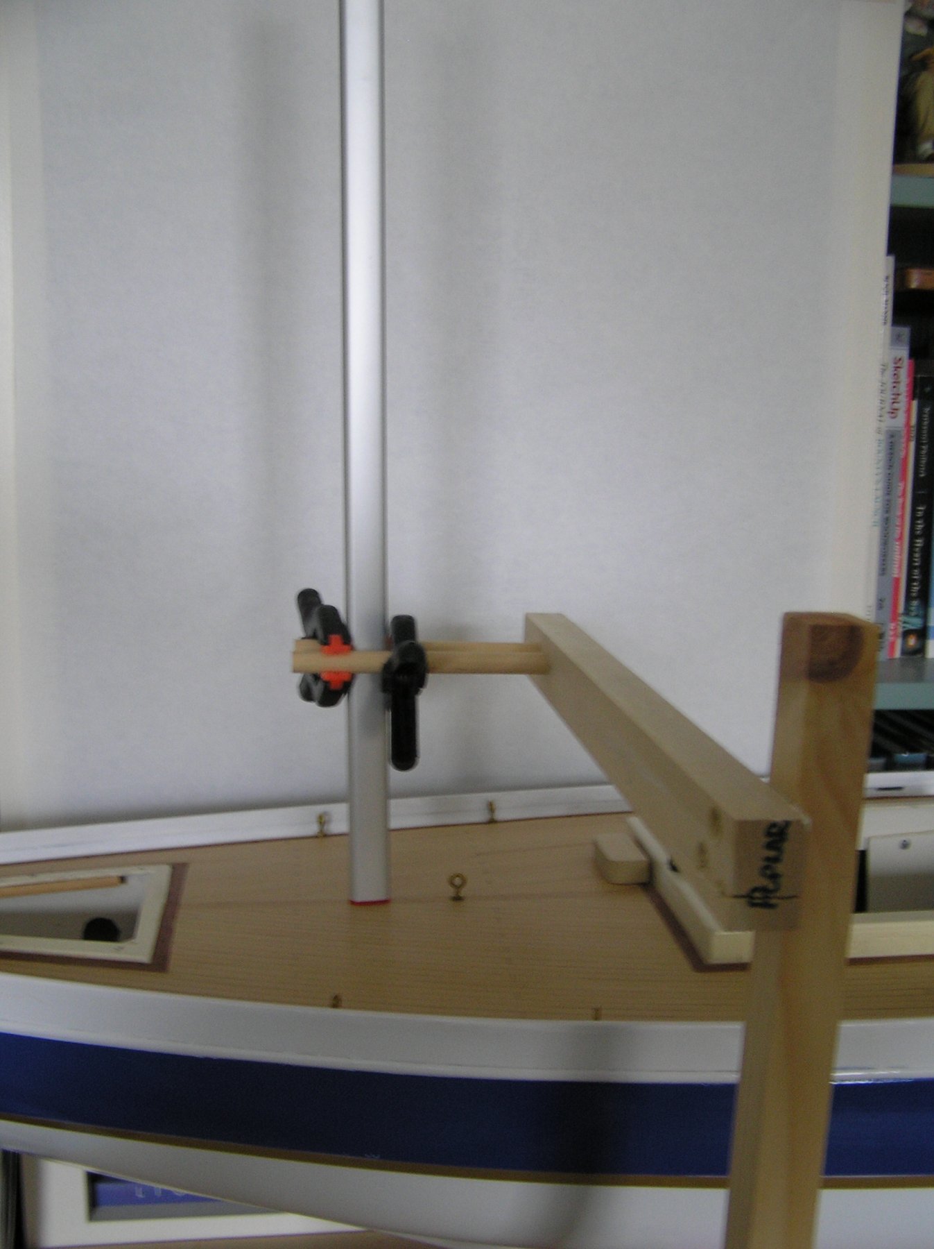
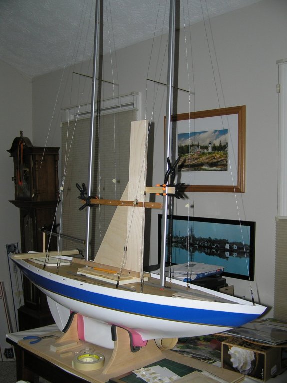
And so it goes. With another mast support (any resemblance to a sail is purely coincidental) jig made up of scrap birch plywood I now have a much more stable way to hold the mast while I rig the shrouds and fore stay. I used the main cabin opening to build a mounting platform for the mast vertical support. It can be reversed forward to aft to address support for the main mast when needed. I decided to move ahead while waiting for the shackles and have temporarily tethered the shroud lines and fore stay to the deck ring bolts. The use of the Du-Bro Push-Pull System will allow final tensioning in concert with the built in mast tensioning system. This will also facilitate mast stepping for shipment.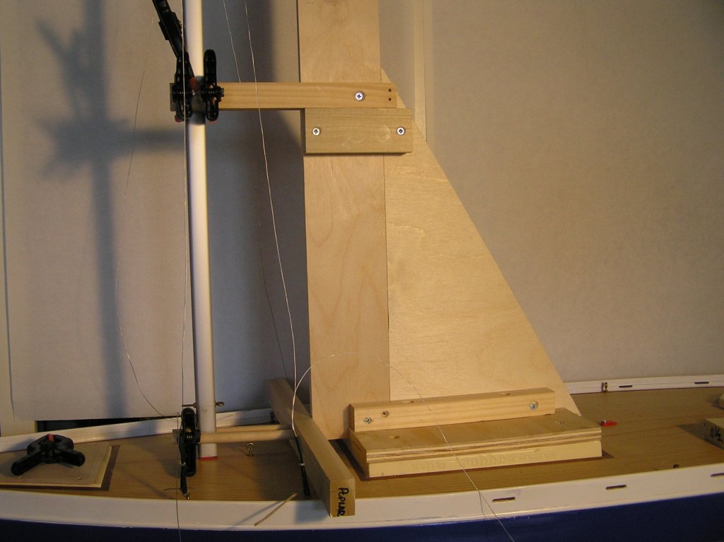
-
Atlantis by Thistle17 - FINISHED - Robbe
Thistle17 replied to Thistle17's topic in RC Kits & Scratch building
Parts from Harbor Models have been ordered but have yet to arrive. In the mean time I have been trying to come up with a stabilizing jig that will hold the masts when I start the rigging. This "rube goldberg" of a support arm seemed to be a decent solution until I replaced the cut off of fore mast with the full length fore mast. It is unworkable as the model, with mast, sitting on a desk high platform, is over 8 feet tall! This makes for a very unstable mast and an accident waiting to happen. Going back to the drawing board.
-
Take a look at this image from Wikipedia. You can magnify it. When doing so it appears to be belayed on a boom cleat. https://en.wikipedia.org/wiki/Gaff_rig#/media/File:Rose_Dorothea-1907-broke_topmast_racing-won_Lipton_Cup.jpg Joe
-
So Rusty, tell me how you got those 1/2" scale shoes in your opening entry of this post? You are the consummate scale modeler! Joe
- 120 replies
-
- 4
-

-
- queen anne barge
- Syren Ship Model Company
- (and 1 more)
-
Atlantis by Thistle17 - FINISHED - Robbe
Thistle17 replied to Thistle17's topic in RC Kits & Scratch building
I keep ruminating over the transport of the model to its home in the hills surrounding Naples NY. I even measured a cargo van last eve and it only had about 5 feet of head room. So I am convinced now that I have to step the masts and re-rig on site. To that end I have found scale (sort of) turnbuckles for the stays and have found close to scale working shackles that I will use on all stays and shrouds. I have ordered Syren working blocks* to sail hauling and the like. Yes I realize that the wooden blocks were not likely used in this era but the brass ones I ordered just didn't allow an adequate sheave hole. More work for me but the end result will work and be convincing. * In coming to a solution I had to communicate with Syren Ship Model Company about the maximum rigging line I could use with the working blocks I wished to order. In just a few hours I had an answer, my order was placed and shipped. How's that for customer care! It's rare today to see such care of customers! Joe -
I have mulled this over from time to time and especially of late with the Atlantis I am finishing for a client. If you follow the thread on this model under RC models you will see it isn't a terribly complex model but has required some "yankee ingenuity" and lots of time. I am only doing it because I really like the people I am working for. Its certainly not the money as I think when it is done I will have earned about $3/hr! Now here is the other end of the spectrum. I know of 2 professional modelers and one has told me his commissions for the museum quality models he turns out range in the 10's of thousands. His clients are business owners and private collectors of means. He is well known to many of us and has been doing this since I first met him in the early 80's. I have to assume he has continued to do so because he can support himself. But those pay checks are such a long way in between. Create these models for the love of it, not the money! Just my opinion. Joe
-
Masterly work. Its a joy to witness your execution of the model. Joe
- 504 replies
-
- 4
-
-
- washington
- galley
- (and 1 more)
-
Dave we were given quite a revealing presentation about 2 years ago by a modeler who had developed a plan, defined the materials set and wrote the construction manual for a model available on the market today. The creator related that it was an iterative process in which he saw numerous deviations in many aspects of his design. A number of the deviations were with the manufacturing process i.e compromises in parts for whatever reason. He took much heat from the community at large for the deviations. Why do I bring this up? Older kits and their drawings suffer some of the same ills, possibly more. Supposedly prestigious archival drawings and renditions in some repositories have been challenged by researchers. I came across this on my abandoned build of the Corel HMS Unicorn. When a design is reduced to a kit there are so many ways things can get out of wack that it isn't even worth listing them. Presently, I am working on a 1980's era model, a very expensive one, and I am finding drawing errors, omissions and the like. We all have become more astute at this pass time and have imposed higher standards on what we accept as "bible". My advice to you is to establish a datum with the body plan. Let the given dimensional data guide you on what you pick as the reference. Have the drawing scaled to meet those dimensional requirements. Redraw/recreate the profiles to the correct scale if you need. Corel Draw is a handy way to get you there as you can scan in the profiles and manipulate them. Of course there is always the research avenue to aid you in resolution of inconsistencies. Perhaps the Peabody Museum may have some drawings you may avail yourself to as I see a reference on the drawing to East Boston. Joe
-
Atlantis by Thistle17 - FINISHED - Robbe
Thistle17 replied to Thistle17's topic in RC Kits & Scratch building
I find I have to keep educating myself about rigging practices for more modern vessels. So today I searched the web for halyard belaying practices for example. The first and most obvious thing I was reminded of was that there was no use of pin rails/belaying pins for this era on most vessels. Most vessels had mast or deck cleats and if needed were alternately belayed to rails that were handy. I will ignore the pin rails surrounding both masts and replace all halyard terminations with cleats. It is fortunate that I did not waste the time building the pin rails. So with some trepidation I move forward. Joe -
Atlantis by Thistle17 - FINISHED - Robbe
Thistle17 replied to Thistle17's topic in RC Kits & Scratch building
Realized this AM that I may have to address the sails at this point even though I haven't even attempted to step the masts. The fore stay sail is traditionally hoisted on" travelers" up the fore stay as I understand rigging. On the RC version of this model this sail is slipped onto the fore stay as the sail has a "pocket" sewn into it. The same is true of the main stay sail. I have to believe this was a model design decision that deviated from the real life rigging. Otherwise one would have had to unfasten the fore stay to remove the sail. Really! So now I must consider the manufacture of stay travelers to make it appear more realistic. Where oh where do I draw the line? Just as an aside the funny looking sail between the fore and main is called a "fisherman" in some references. The wish bone I have further learned made it easier to haul just the sail and not the gaff (as in a gaff rigged sail). I have further learned that this "boom" could do lots of damage in heavy weather to the main. Seems like a lot of trouble for a bit more effectiveness in light weather. Joe -
Atlantis by Thistle17 - FINISHED - Robbe
Thistle17 replied to Thistle17's topic in RC Kits & Scratch building
Finished drilling all mast holes, fore and main, and attaching most of the hardware. Shrouds have been fed up through the mast tops and then returned through companion return holes, leaving a small loop at the mast tops. There is an interesting adjustment mechanism built into the design. The loop formed at the top of each mast by the shroud feeds will be attached to an adjusting screw, threaded follower that will ride up/down the adjusting screw. The screw will stretch/relax the shrouds when adjusted. This is what I am hoping will allow stepping the masts for transport. The next step is to prepare the fore, back and between mast stays. The fore and back will be adjusted with some miniature turnbuckles purchased from Harbor Hobbies of California. I ordered some laser cut brass pulleys from this supply house but I think they will not be used due to the scale. My next approach is to swap out all blocks for Syren "you build" blocks of a better scale. Joe -
Atlantis by Thistle17 - FINISHED - Robbe
Thistle17 replied to Thistle17's topic in RC Kits & Scratch building
In thinking about the fore mast extension, of 20 mm more, I thought of several ways to try to fix the problem. Then I had an epiphany! I realized if I took a brass tube of outside diameter slightly larger than the inside diameter of the mast I might be able to squash it down to fit the "tear drop" shape of the mast extrusion. It took several passes in my workbench vise but I managed to make the round brass tube an oval of correct size to achieve a friction fit inside the mast. I then CA glued about 4 inches of the tube into the mast and then press fit the extension onto the exposed brass tube and CA glued that. It made an almost imperceptible joint. Any CA glue that leaked out was cleaned up with lacquer thinner. I think I can live with the outcome since the model is a static model and the mast will always be under compression when the shrouds are attached. Joe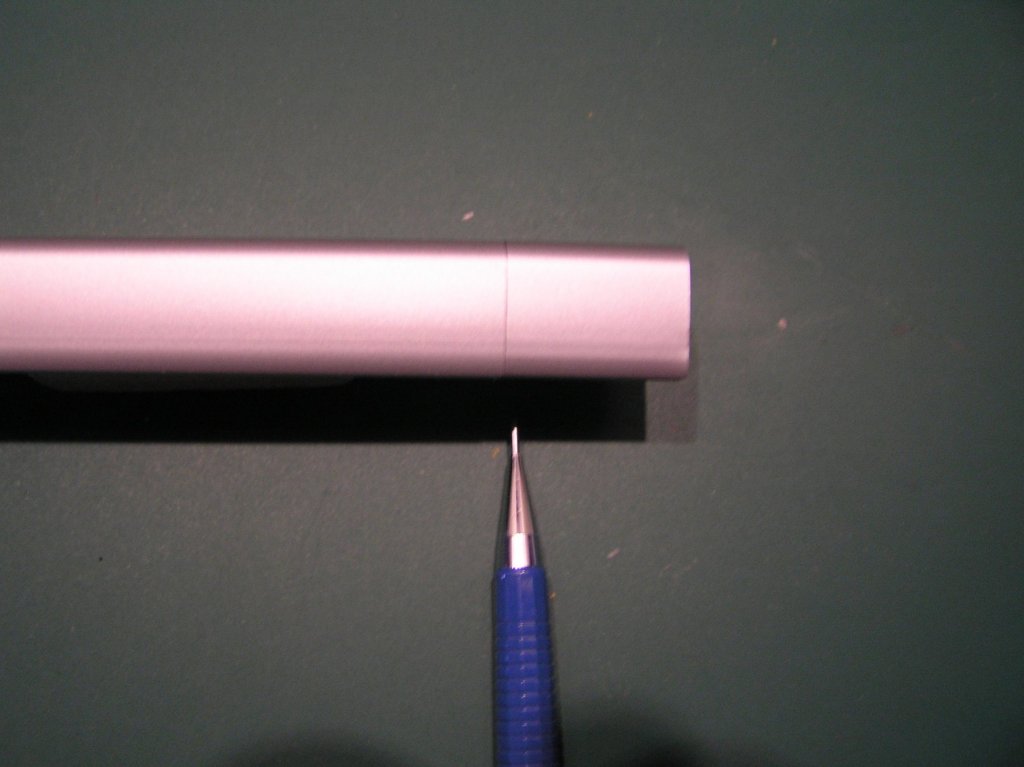
-
Atlantis by Thistle17 - FINISHED - Robbe
Thistle17 replied to Thistle17's topic in RC Kits & Scratch building
Just completed the jib, fore and main booms (top to bottom view). I ended up cutting up the genoa kit I acquired to get the aluminum material. The booms I had were a different anodize so I chose not to use them. I got to use my recent purchase of a Sherline Vertical Mill to machine all holes and mill of the slot to receive the main boom pivot. While the tasks were basic, I have to say it was a shear joy to perform these simple tasks with the mill. I don't think I would have achieved the accuracy with any other tools in my shop. Those little silver 'cans' on the jib and fore booms actually have a working swivel at the base to support free movement of the sails under RC control. The instructions and drawings continue to slow progress because of omissions. I am marking the drawings up and moving on. My next task is to extend the fore mast. I will have to cosmetically dress the extra 20 mm addition to hide the extension interface but I think it will all turn out in the end.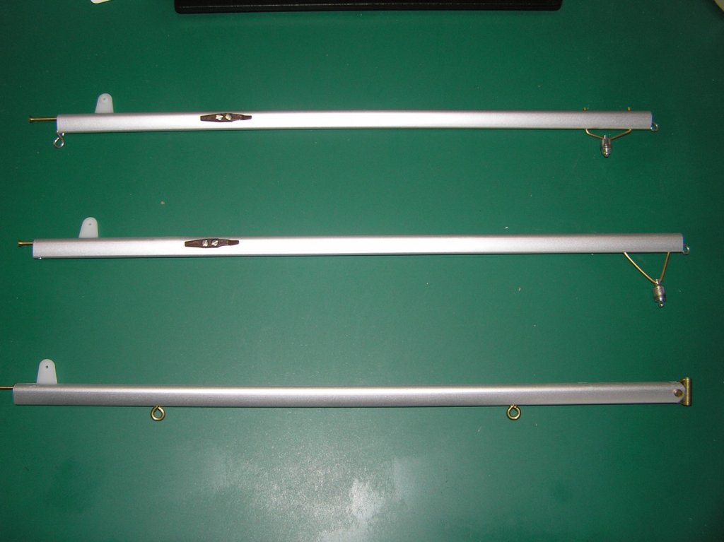
-
Welcome to the forum Neil! You will discover a rich fount of knowledge and inspiration here as I have. I personally think this is the best thing that has happened to The Nautical research Guild and model ship building in a long time. Joe