Thistle17
-
Posts
1,054 -
Joined
-
Last visited
Content Type
Profiles
Forums
Gallery
Events
Everything posted by Thistle17
-
 Peter the mahogany planking was 1/16 for the model I built with my grandson. We used medium so we could move it around as its open time was about 20 seconds. Some of the planks needed a return fill with the thin as they just didn't lay down to our satisfaction near the bow. A slight application of the thin and finger pressure holding did the trick. The model is 2 years old now and there is no sign of separation. I have also used DAP Rapid Fuse All purpose Adhesive to bond wood to ABS plastic. It is an interesting product as it can be gently removed and reapplied within 30 seconds of the first application. Afterwards it is fixed and cures in about an hour. I checked with DAP and the only thing you cannot do is glue ABS to styrene for example. Joe
 -
I have no experience with this filler but have used a state side product called RAGE auto body filler on a PVC skin for an RC model that needed fairing before it was planked with mahogany. Some of the filler was still present after sanding. I was timid for the same reasons as you. We finally plunged ahead and fastened the planking with CA glue and it worked. We used the 20 second variety. I might suggest that you make up a sample substrate wood/filler and try something other than PVA. PVA bonding requires penetration into both surfaces. Joe
-
Barbara I sit in front of this PC and just shake my head at what is going on with you and your dad. It is so bitter-sweet. We have had 2 family members both with early onset of this disease. It was so painful to witness. Simple tasks became stumbling blocks for them. One has to show such patience and understanding to be a witness no less a participant. Your dad is remarkable as well. Be vigilant in his use of power tools. It is too easy to get in trouble even with modeling tools. God bless. Joe
-
Bending sharp edges on brass strips
Thistle17 replied to Sandor Laza's topic in Metal Work, Soldering and Metal Fittings
As Carl relates it is quite difficult to get brass to not round over when bent. As you did not state the thickness I have to assume it is less than or equal to 0.5 mm for your application. If you heat it, it will bend more satisfactory. You can use a small table top vise to crimp the fold and get better results yet. The combination of both should prove even more satisfactory. Joe -
Generic Sharpie by DocBlake
Thistle17 replied to DocBlake's topic in - Build logs for subjects built 1851 - 1900
Dave I am impressed with the jig making as with your model build. You invest well where it counts even if it may never be seen after the model completion. Great work. Joe -
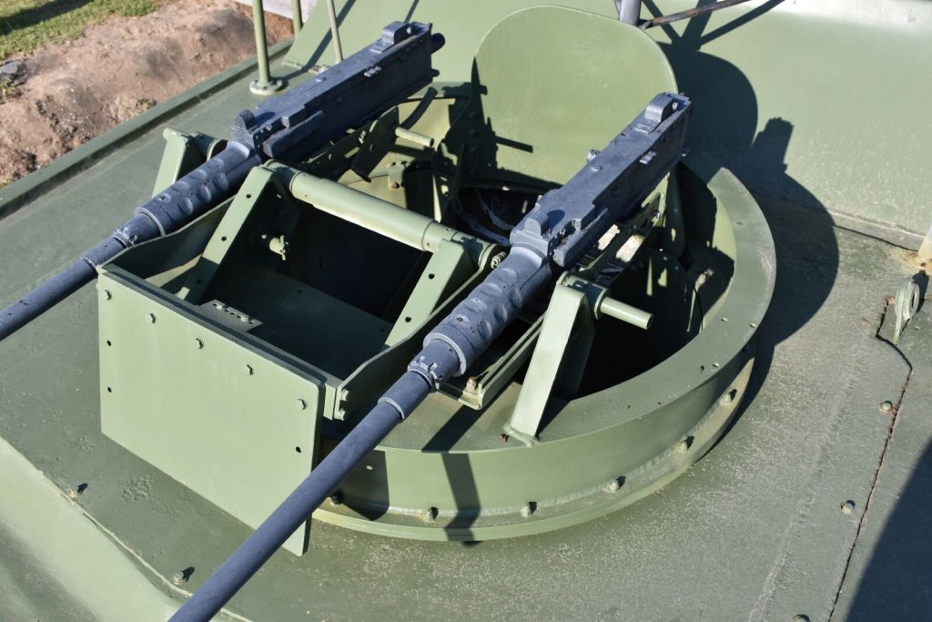
We just received a windfall of pictures from the folks at Patriots Point in South Carolina. They filled a request we had made for better detail pictures of the PBR they have there. For this we are truly grateful. Here is just one of many showing detail that is not on our drawings from either the Navy or Maryland Silver. Update 5/14/18: After our meeting this week and a review of the recent photos sent to us we have concluded that we need to sort out the configuration of the model we will ultimately build. We realize that there were so many upgrades in the field that we have to settle on some base line and proceed from there. To that end 2 of our members are putting together a library of photos from on line and Patriots point sources to decide on the final configuration. It is all in the details for example the guns shown. There are at least 3 versions: a dual set close together, a dual set as shown and a single barrel version. This decision was easy to make. It will be as shown. However other subtle changes have to be accounted for elsewhere.
-
I have been following these threads of "technology" introduction into this wonderful hobby/art form. I am also a woodworker and have seen the same thing happening there. Tonight I attend a "Period Furniture" SIG and the topic is on a newly acquired CNC vertical mill with attendant new software for design. One product this individual makes is a wooden bench vise screw, a very complicated part. I find this all so fascinating. My background is in real time machine control but I find myself fighting what I perceive as a "tension" with these new technology introductions into any of these pursuits. Where do I spend my time is probably at the heart of the tension as I am beginning to realize I am not immortal. Do I spend my time at the computer or do I spend my time at the bench? How do you early adopters feel about it? Joe
- 132 replies
-
- 4
-

-
- charles martel
- battleship
- (and 1 more)
-
Atlantis by Thistle17 - FINISHED - Robbe
Thistle17 replied to Thistle17's topic in RC Kits & Scratch building
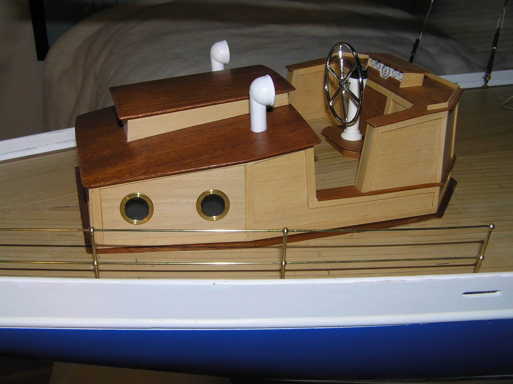
Detail continues to be added to the model. All portholes, with glass, have been installed. Ship's wheel and vents also have been added. The last remaining element for the aft cabin is to fabricate and install the grab rails. The first segment of stanchions has also been installed but not completed. I tried to fabricate the entire top grab rail in one piece but was unable to install it to my satisfaction.The stanchion post holes were drilled undersized so that the threaded base of the stanchions would screw into the deck for a snug fit. Doing so limited my degrees of freedom for fitting the forward transition element of the top rail into the deck (something like the aft termination). I had to cut the top rail off mid way into the top hole of the forward stanchion and will solder the mating (cut off) piece into the stanchion to achieve the end point. I discovered a new tool (to me) that has helped cut the brass rails. Previously I was using a typical side cutter to cut the thin brass rod. It leaves an irregular end that is splayed a bit making it difficult to pass the wire through the stanchion holes. I ran across a costume jewelry cutter that has a 'chisel' cutter on both inside and outside edges of the cutter (unlike my side cutters). It produces a much cleaner cut off and easily passes through the stanchion holes. Joe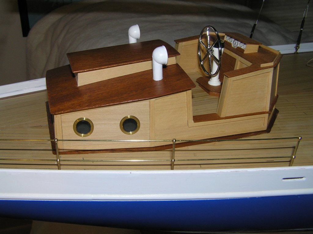
-
A number of our group have seen Rusty's model of your first version. It was a delight to behold! So this version should be nothing short of spectacular and a joy to build with your continued refinement of technique. Now the big question is how long do I have to stand in line to buy one?????? Joe
- 1,784 replies
-
- 4
-
-
- winchelsea
- Syren Ship Model Company
- (and 1 more)
-
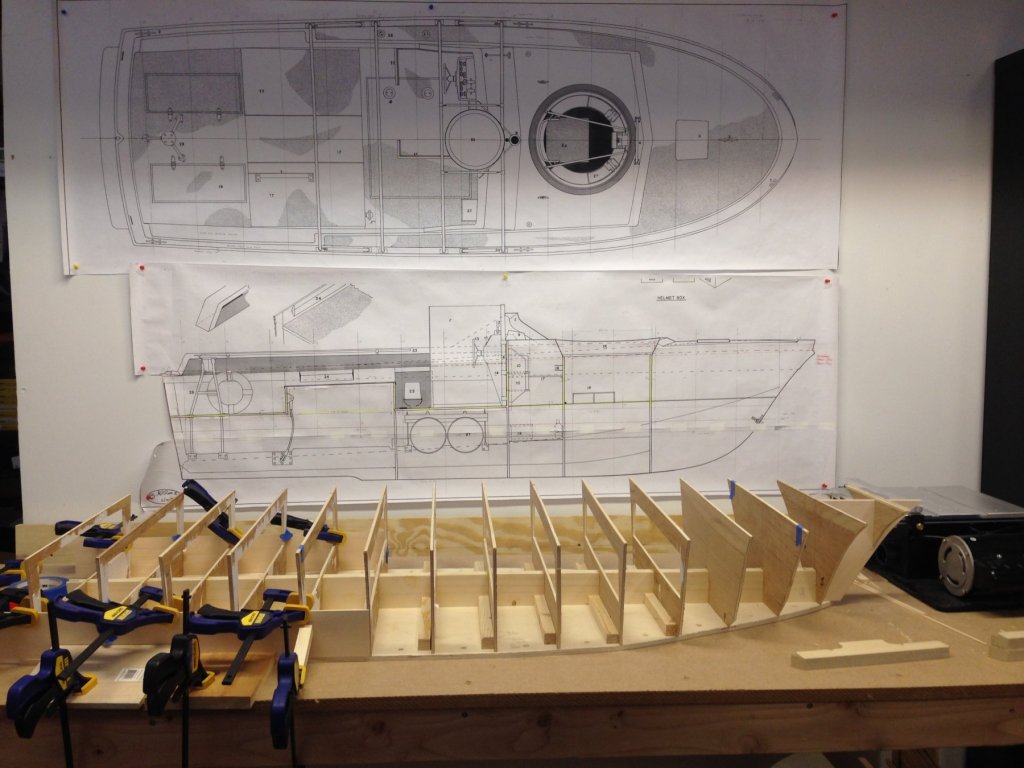
Today marked the beginning of hull planking. You will note two sheets of (3" X 24") bass have been applied at the waterline (one per side). We have let them run "wild" at the transom as that framework is being developed "off line". This should be integrated at our next build session. The hull shape enabled us to use whole sheets of bass at this point and we will continue to do so until the area defined by station #4 - #5. This starts the more extreme curvature and includes the chine area that is above the waterline. The model spline is the height of the boat floor (minus the deck plating) and that will be added in all the way forward to the gun turret. The bow area as we see it now will be filled in and sanded fair prior to advancing planking to the bow. Of note are the full size drawings mounted behind the model which will definitely support our continued model build. Joe
-
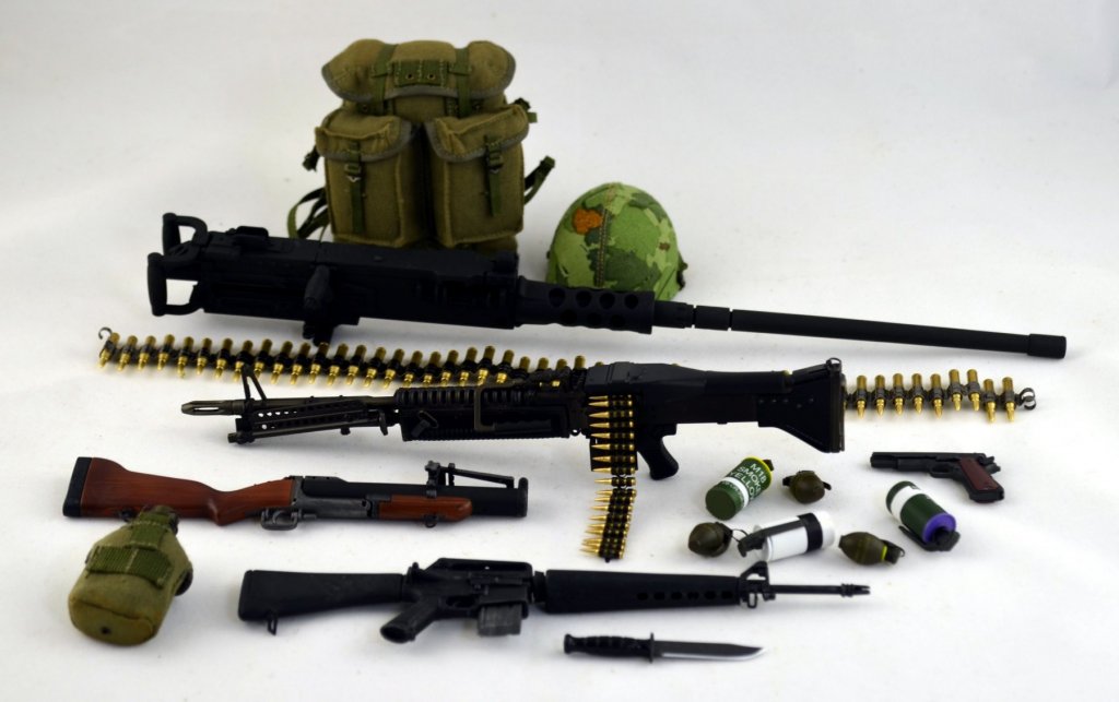
In the prior post I had indicated there were some incredible scale accessories which we can use on the PBR model. In the attached photograph here is a sampling of the items. Note the 50 caliber machine gun with its associated ammo belt. Two of these are to be mounted in the forward gun turret. One will have to be slightly modified to change the "handedness" of the cocking mechanism. These should lend much interest to the final display for the museum.
-
Atlantis by Thistle17 - FINISHED - Robbe
Thistle17 replied to Thistle17's topic in RC Kits & Scratch building
As they say the devil is in the details. With my limited experience with machining metal and other materials on a lathe or mill I was stumped as to how to machine the plexi-glass (1/16") to fit the brass portholes. Since there are 10 instances I was not about to hand cut them out and file them to fit. It occurred to me that the methodology shown in the attached photo might work. On my Unimat I attached a 3/4" plywood secondary face plate to the Unimat face plate. To this I attached small squares of the smoked plexi-glass. Using my cutoff/parting tool that I honed to a very sharp cutting edge I slowly turned the plexi-glass to the proper diameter. It took 2 attempts to get the almost correct diameter. On my first pass the "glass" grabbed near the release point. Prior to the second pass I trued the plywood secondary face plate. So doing solved the grabbing problem. I did find that the plexi-glass melted a bit no matter how slowly I fed the cutter. Some finish filing addressed the rough edge and fit. I was tempted to stack a few plexi-glass plates together to speed up the process but decided I was pushing my luck. Only 7 more to go! Joe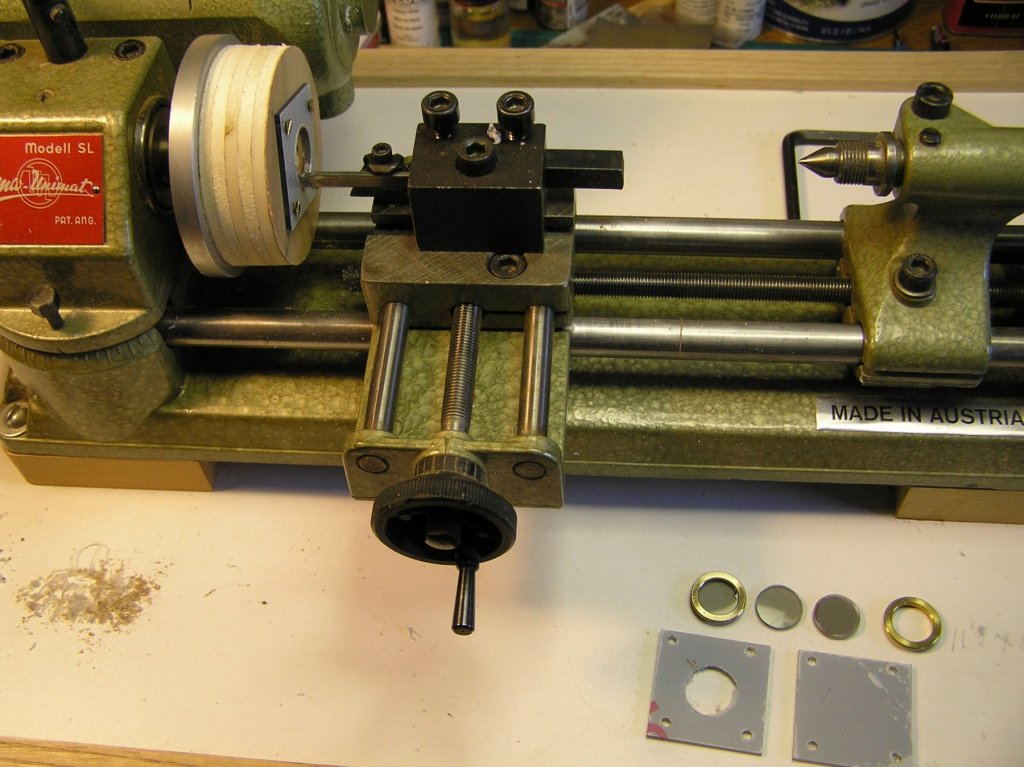
-
I have heard it said that sometimes the journey is more important than the destination. I wish you both a pleasant and enjoyable one. Do continue to post your combined work. Joe
-
Simplified Lathe and Mill Operation
Thistle17 replied to Roger Pellett's topic in Modeling tools and Workshop Equipment
I think this thread can be most useful to many of us "wana be" machinists. I would vote keeping this alive. For example I have to machine some plexi-glass windows for portholes approximately 14mm in diameter. I have a modeler's vertical mill that I thought I could use in conjunction with a rotary table but I just can't quite get there mentally. Or should I be using another method such as a fly cutter? Joe -
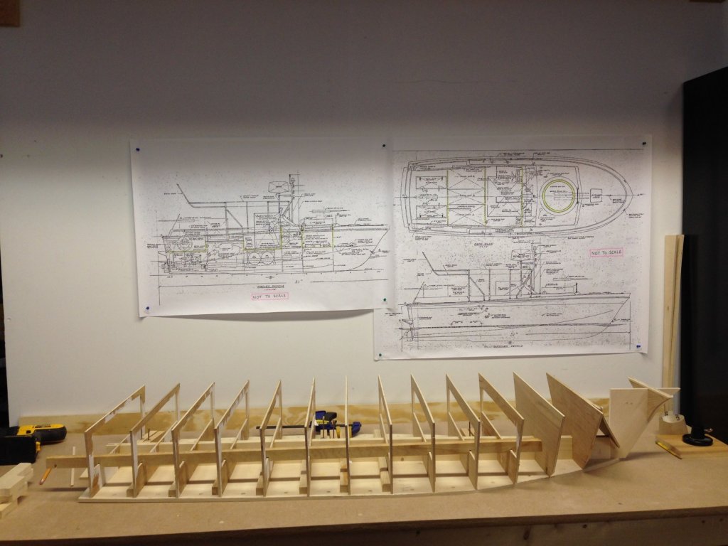
Yes we are still intending to build this model for the museum. We made incremental progress between March and today. A new mobile bench has been built and we finally started fairing the bulkheads. We are about 70% complete with the effort. As I commented before it still looks ragged in this state but I am sure once the skin is completed it will begin to look more respectable. The director of the museum has been collecting fittings and artifacts at the 1:6 scale that are just so realistic it boggles the mind. In later posts I will be showing some. Here is the model mounted to a substrate with a stiffener shown within that has aided in sanding the bulkwarks. Drawings on the rear board (these are the Navy's drawings) are not to scale but aid in our build needs. We have drawing to the 1:6 scale that we reference for the model as well. As you will note lighting is less than adequate at this point so we will be working on that as well.
-
I abandoned my Corel cross section of the Constitution years ago for the same reason Anthony states. It just didn't measure up to what one would consider a quality endeavor. This is likely to be a stellar offering and considering the barge success I guess I will have to pitch a tent curb side at your shop to be in line for this offering! Joe
-
Thank you all for your information. I just didn't understand the transition time. And as I said Cast Your Anchor came through beyond my expectations. I withdraw negative comments. Joe
-
Oops I just received an e-mail and they apologized for the delay and the lack of answers. They stated they were having computer problems at their site. Also they have refunded my payment through Pay Pal. In this case I have to cut them some slack. Hmmmmm! Joe
-
To my surprise and dismay the order I placed showed up in our post today. The surprise I never heard from them after 2 e-mail attempts. The order status was never updated after the order acknowledgement. What showed up was 2 of the 6 identical items assembled and the other 4 needing assembly. The web site catalog was quite vague about "assembly required". In total the order took 14 days from Canada to my home just across the border. I will make this my last purchase from this company. Joe
-
Atlantis by Thistle17 - FINISHED - Robbe
Thistle17 replied to Thistle17's topic in RC Kits & Scratch building
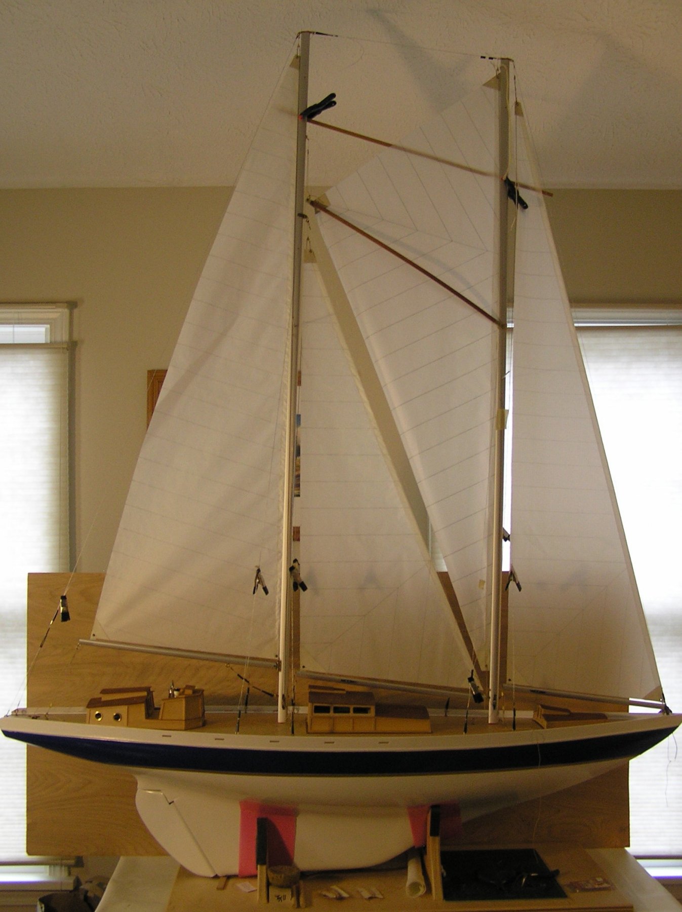
Looking back I observe that I raised the masts in February of this year. Now I have not been working this model full time but I certainly have put a decent amount of time in its advancement. Below is the latest depiction of its progress. As shown all sails are up and either tethered or awaiting to be secured. You will notice that the shrouds and stays, for the most part, are temporarily secured with miniature alligator clips. The reason for this is that I am unsure at this point if I should crimp the Du Bro fittings at the deck or wait until I deliver the model (recall I have to step the masts for delivery). Note that the wishbone is finally in place. Also note there is a temporary "spreader at the mast tops to maintain the mast vertical alignment in light of the temporary shroud and stay situation. The down haul rigging for the wishbone is not in place yet but will be as soon as I complete some deck bitts to tether all "floating lines. As I progress I am reminded of a song lyric that goes "the ocean is a desert with its life underground". I offer that as I under estimated the task of converting this to a static model. Most of the operating rigging for this model is below deck. As an RC model most top side rigging is tied off close to its need or fed down below through small tubing cleverly disguised in deck appointments and ultimately secured to pulleys, cleats and the like. In addition, on modern sailing craft, there are few traditional cleats. Most are cam cleats which are strategically placed on cap rails, outcroppings of the hull or some other means. There is neither the opportunity to do so here or are there parts that I could use that I know of. Hence I must compromise, much to my dismay. To move this model to completion, I have yet to trim out the deck furniture with glass simulation (smoked polycarbonate), and add skylights, grab rails and air vents. I have to add the stanchions/railings and aforementioned bitts. I also have to model the life boat which was missing from the parts I received when I took this on. There a few deck fixtures I have to address such as the anchor (which was to be glued to the outside of the port side of the hull) and the anchor winch which has to be fabricated. Might I say that the anchor placement authenticity is troubling me. I will leave it there. Joe
-
I do not know if any of you folk have attempted to do business with this company. I recently tried and am now suspicious, at best, about this operation. I placed an order recently after being vectored to their web site. I placed a small order and paid through Pay Pal. I did receive an invoice but I suspect it was computer generated. There was no indication that parts were out of stock. The invoice only said "Shipment Pending". I tried e-mail contact and received no reply. I then went to a Google Search and discovered that "Business is Permanently Closed". Several Google reviews mirrored my complaint. If one goes to the web site directly it is still active. I now have Pay Pal interceding. If this is a valid business it certainly doesn't know how to treat customers! Either that or I am spoiled by the reputable businesses I deal with state side!
-
This is a bitter sweet tale you tell Barbara. The model speaks for itself but your being there by his side shouts out your love for him. We all should be fortunate to have a daughter like you. Thank you for sharing. Press on and keep in mind that the journey may be just as important as the task. God bless you both. Joe
-
Atlantis by Thistle17 - FINISHED - Robbe
Thistle17 replied to Thistle17's topic in RC Kits & Scratch building
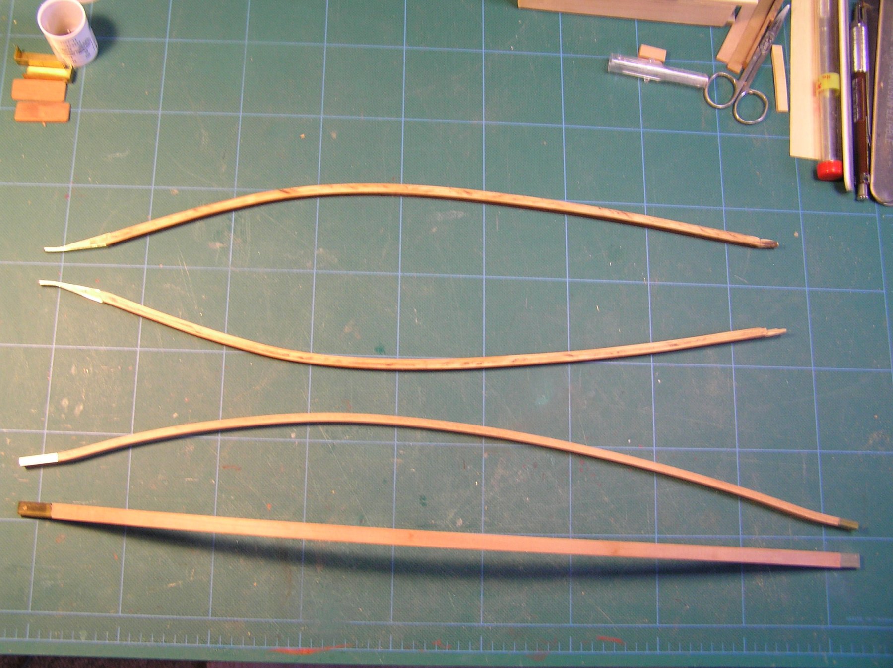
It is nearly 2 weeks since my last post. I must admit that after hours of web search and doodling I have failed to come up with a decent rendering of what the mast attachment for the wishbone should look like and I might add something I could readily fabricate. So I have had to admit "defeat" and move on. Since the model is to be a static display I have decided to fabricate a simple fore mast clip that wraps around the mast's teardrop shape and gives some appearance that some attachment device does exist. Pictured below are the remade wishbone elements. They are made of mahogany strips (2) and have been wet formed on a mold. The elements when dry were glued together and trimmed down to 5/16" X 5/32" dimension. To each end I have let in a brass rectangle tube (of the described dimensions) to give some realism to the elements. Note they are longer than the original wishbone elements supplied in the kit as they now will be attached to the mast and not the sail. I also had to ensure that the mast location for attachment did not interfere with the shroud lines fed down through the mast tubing. The left most ends still need to be tapered to conform to the mast cross section. I plan to do this with some mill machining and finish off with files. The members will be screwed to the fore mast/fashioned collar. The right ( free) end will receive appropriate rigging elements to (1) pull the sail taught and (2) facilitate both up haul and down haul rigging to keep the sail trim. Since all sails will be positioned along the keel I will avoid having to address the rigging mechanisms that would normally be required on a "reach" for the fisherman sail. To some these compromises would be frowned on I am sure. However I have to take this path else the model will never get delivered! Joe
-
Outstanding shop organization and at the street level to boot. I miss my old shop's access to that level. Your efforts will continue to pay off and responding to Michael Mott's comment about "at my age...." I would offer we are not pushing up clover yet so we all need to keep going! It's like a poster I used to see on the workout room at work. "There is no finish line"! I am inspired by what you have achieved. Joe
-
Sherline mill and lathe questions
Thistle17 replied to Landlubber Mike's topic in Modeling tools and Workshop Equipment
Mike it is always a "tug" of what to buy and which version i.e. longer bed etc. My DRO mill has the 13 inch bed and I vacillated about the longer bed as well. It has not been missed. Recently I have been milling aluminum masts for the Atlantis and they are about 5 feet long. It is a bit awkward but I manage by adding a "rest" on the free end and moving the work piece (mast) along as needed in the vise, keeping the "y" position steady when I have to work over more than the bed will allow. Granted the things I am doing; drilling holes. milling a flat etc. do not require extreme accuracy. So at this stage of my usage I do not see the need for the longer configuration. Joe