wyz
-
Posts
411 -
Joined
-
Last visited
Content Type
Profiles
Forums
Gallery
Events
Everything posted by wyz
-
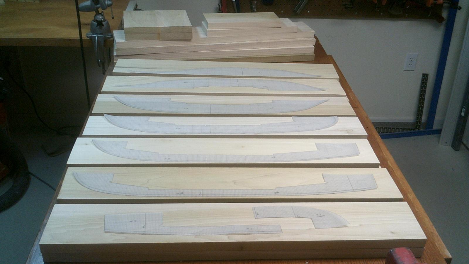
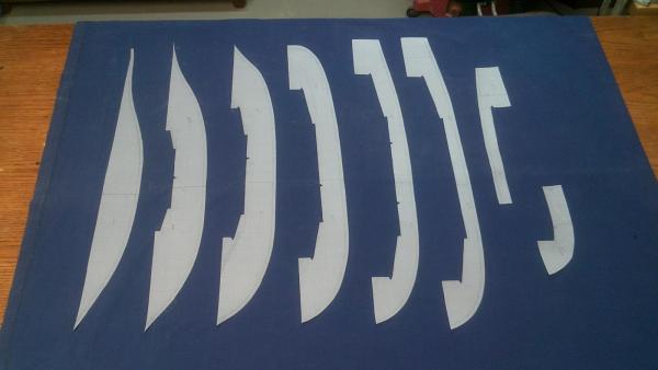
 Starting the Build After all the preliminary stuff has been taken care of I can now start building the model. Hallelujah! First things first, go out and get some lumber. I went to a lumber yard and purchased 5 - 12' long x 1 1/2" thick x 6" wide planks of yellow poplar. They milled the wood on all six sides and when I left the yard I took with me 20 - 33" long x 1" thick x 5" wide pieces of wood. Eight inches of planer snipe from each end of the plank was cut off and thrown away. I was very happy with the milling job the lumberman did so I crossed his palms with gold. We both walked away smiling. I got the wood home, took it down to the shop and stacked it to air dry for a few months. For reason I didn't have any control of it end up being 7 months. When I was ready to start the build the first thing I did was take a pad sander with 60 grit sandpaper to the wood. On some boards the planer went against the grain and caused a furry surface that needed to be taken off. Next I looked each piece over very carefully to decide what lift it would be part of. I make each lift from two pieces of wood glued together. To get timber 10-12" wide that doesn't have some cup is difficult. It's just far easier to get a flat lift if it's done in two pieces. I learned this lesson the hard way. When I match the two pieces of wood I try to make sure there are no height differences between the boards, even very slight ones, because they would have to be sanded or planed out first. No thanks! You also have to take knots into account when pairing wood with the templates. Care at this most early stage of the game can save you major headaches down the road. The photo above shows the mylar templates that will be used with each pair of yellow poplar boards.
-
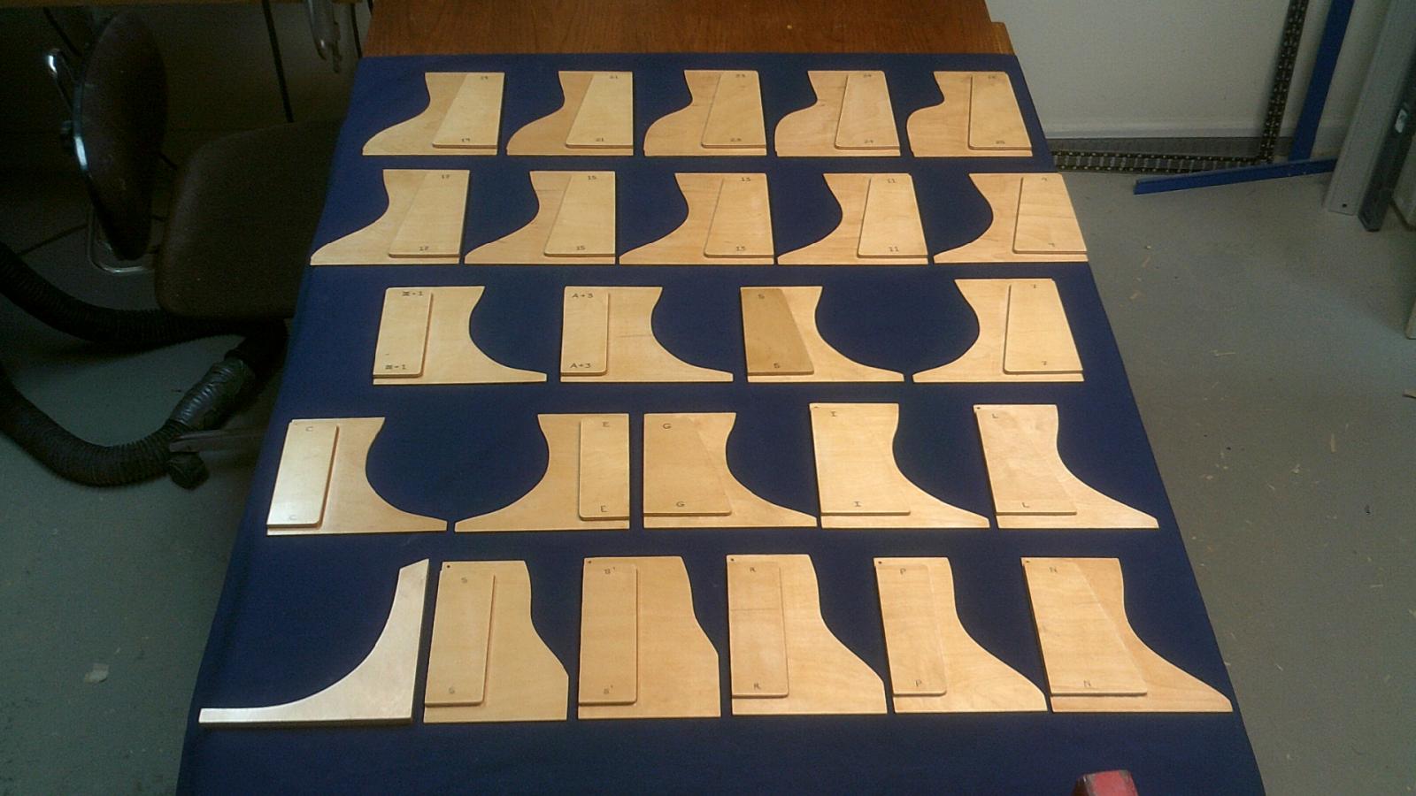
Plywood Hull Shaping Templates To shape a bread and butter construction hull you need to make a set of rigid templates. Years ago I used to make them from 3/32" 5 ply aircraft grade plywood but that wood has become expensive today. With my last model I used some cheap 1/8" birch plywood and, sadly, regretted it. The templates warped and twisted on me something awful. What I did for this Camilla build was to go to a local cabinet maker and buy a 5'x5' sheet of furniture grade 1/8" Baltic plywood. The templates made from this were then reinforced with a 1/4 " piece of furniture grade plywood glued to them. I then gave each template 4 coats of polyurethane. They turned out fantastic, straight as can be. The polyurethane serves two purposes. It acts as moisture barrier helping to prevent any movement, and it allows me to clean the pencil graphite from the templates much easier.

-
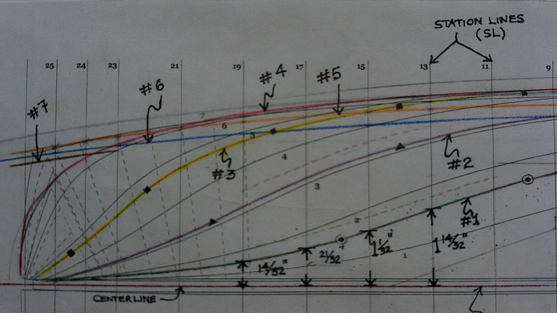
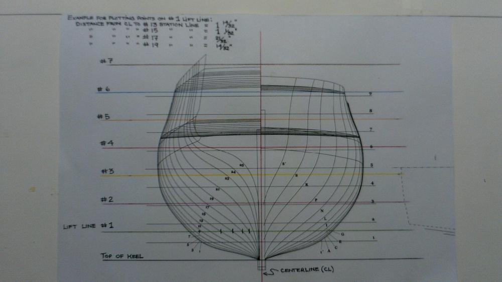
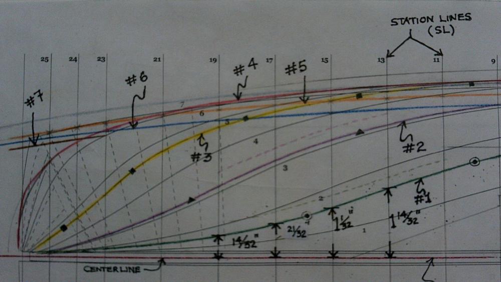
The Lift Templates To build the hull I need to glue several pieces of wood together. They are called lifts. Obviously each lift has a different shape; so the question is how do you determine what that shape is? When one of the MSW scratch builders contacted me and asked for clarification on something I wrote in making the templates I realized how vague it was and that I assumed too much that viewers had knowledge of certain things. I was wrong, so now I would like to rewrite and to provide some more illustration on this topic to help make it clearer. The first step is to get the hull's body plan in the scale you're working to. On it you will see the shape of the station lines (aka section lines), forward on the right side and aft station lines on the left. For this I use Alex Matvijet's plan for the HMS Sphinx, a sister ship of HMS Camilla. Unfortunately for me the distance between waterlines (aka lift lines) on his plan are only a hair over 21/32". On the actual ship this would be about 2' 8". Since I'm using 1" thick lifts for the hull's construction (4' on actual ship) I need to redraw them on both the body plan and the half breadth plan. To start I mark off every inch going up from the top of the keel on both sides of the body plan. When this is done on each side I connect them with horizonal lines drawn with different colored pencils. I have now established the new lift lines on the body plan, and they will be at 90 degrees to the centerline. With this done you now have to measure from the centerline to everywhere it intersects a station line on all eight lift lines. After doing this you will end up with pages of measurements, much of the information needed to draw the shape of the lifts. I write all these measurements in a notebook. Now you have to go to the half breadth plan and plot them. When all the station line points for a given lift are plotted you then simply have to connect them. For this I use a set of ship's curves and I draw these lines with the same colored pencil I used on the body plan for each different lift. This is helpful, especially if you use plans that already have lift lines marked on them. Other model builders, so not to deal with so many lines, may want to make their own have breadth plan. This is easily done by drawing a long horizonal , the centerline, and then marking off where each station line is from simple ruler measurements taken from the sheer plan. Now that this is done you have the shape of the lifts. NOT ALWAYS! What happens when you get to a lift above the wales? Sometimes there is tumblehome!!! When this happens the widest part of the lift is at its bottom, and you ALWAYS want to plot to the widest point for any lift. That said, use the measurement from the previous lift at that particular station line. If you don't take this into account your lift will be too narrow when you make the mylar templates. This mistake undetected mean you will be buying more wood! Look at the body plan and you can see what I'm saying. Be very careful with this as it catches a lot of modelers. Also, I usually add an extra 1/4" to these measurements to insure I have enough wood when I do the initial rough shaping of the glued up hull. On the partial picture of the half breadth plan I show some of the extra allowance on the no.1 and no.2 lifts as dotted lines. If you would not be too aggressive with the power tools, be very accurate in drawing the lift shape and your alignment is perfect when the lifts are glued together, then 3/16" or 1/8" allowance might be ok. That's too close for me. Once I've established the shape of the lifts with the added allowance I then plot them on 1/8" gridded mylar drawing film. Remember to draw the midships line on them. The last step is to cut them out. On the drawings below, both body plan and half breadth plan, I give an example to show how to do the plotting of four station line points on the first lift, numbers 13, 15, 17 and 19. It's pretty much self explanatory. I have to apologize for the lousy quality of the photos of the plans. Note that when I cut the shape of the templates from the mylar I also cut some out from the middle. Why? Several reasons. Most importantly, when the two half lifts are glued together to form a whole one and it is about to be glued to other lifts you have a place to put nails into to keep the glued lifts from slipping out of place. Secondly, it reduces weight. Thirdly, when the time comes it makes it easier to shape the interior. Lastly, it affects wood movement. In an ideal world you want your wood to dry out, or at least to be hydroscopically stable in your workshop environment. Sadly, not all model builders wait long enough before using the wood. When that happens the wood will lose a greater amount of water over time and you will get more shrinkage. If the wood is going to shrink you want that to happen before you start building, not after. The general rule is that the wider the board used to make a lift the more shrinkage you will see. Cutting wood out of a lift adds to its stability. Also, bear in mind that the sapwood of a species absorbs a greater amount of water than the heartwood. As you would think this too affects the drying process and shrinkage. There is an excellent book written by R. Bruce Hoadley on wood properties and characteristics entitled Understanding Wood, a craftsman's guide to wood technology. It's a very informative book, albeit somewhat technical.
-
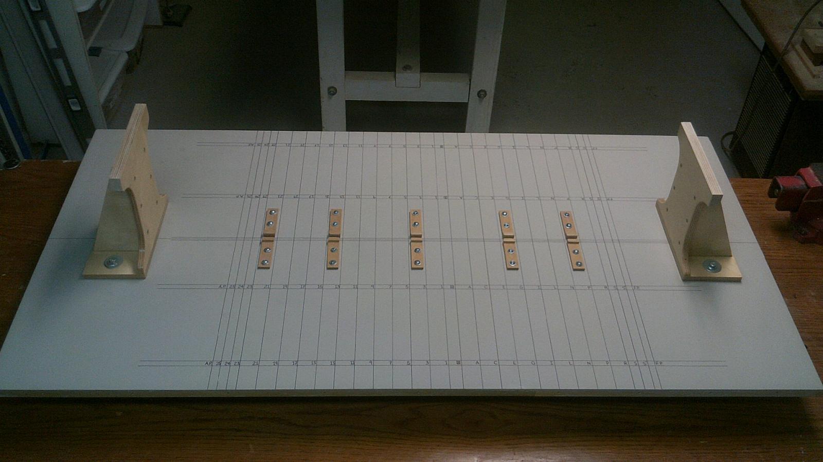
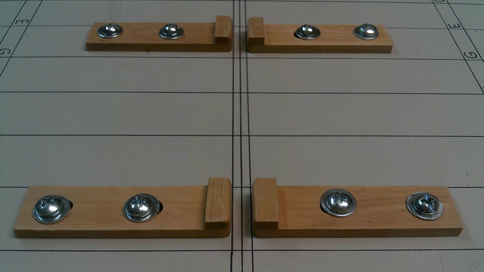
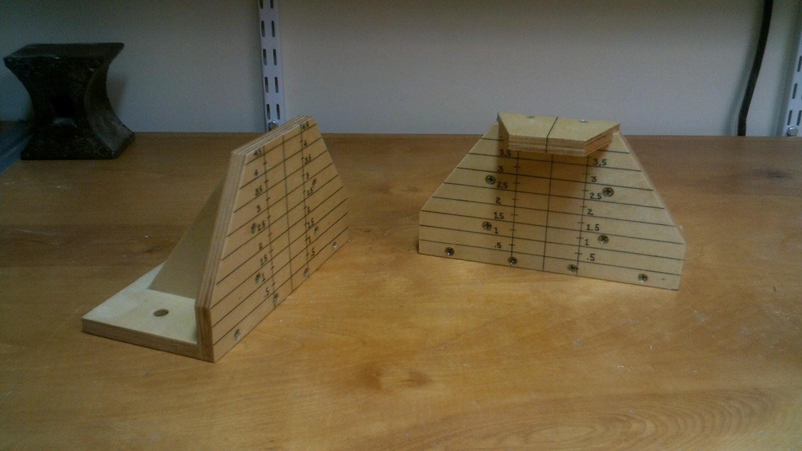
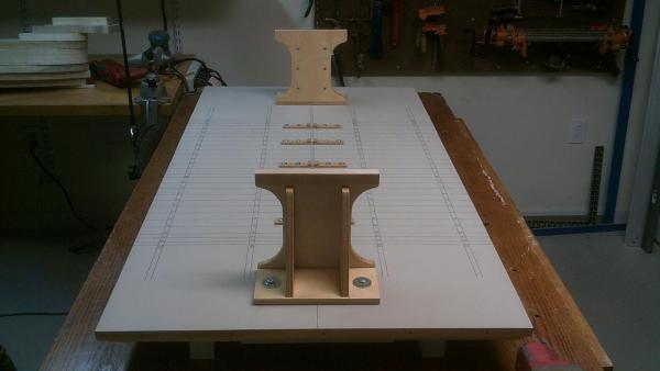
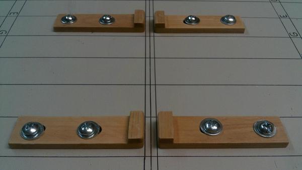
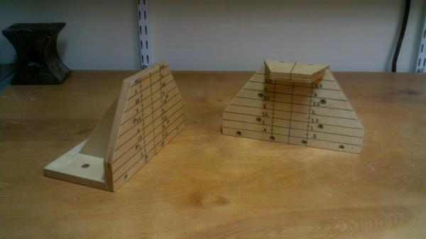
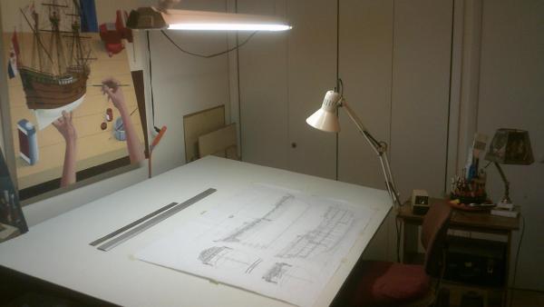
The Building Board Because I'm doing a bread and butter construction where I use templates to shape the hull it's imperative that surface is as flat as you can get it. Even the smallest deviations from flat can cause an error using the templates. I know this to be true because in an earlier attempt I glued a new 1/2" thick piece of plywood on top of an old construction board and had problems. My intentions were good but the board had slight undulations on the surface. The board I'm using now is made from a really fine piece of 3/4" thick furniture grade plywood reinforced with two very straight and stable pieces of hardwood running the length of the table on the underside. I applied several coats of polyurethane on both sides to seal the wood from moisture. I then painted the top surface with three coats of a flat, light gray latex paint. Afterwards the board surface was checked and rechecked to insure flatness. The next step was to draw on the board with an ultra-fine point Sharpie pen the center line and all station lines, including the fore and aft perpendiculars. Also I drew the station line numbers and letters. I then made five pairs of keel blocks from Castelo boxwood. After drilling holes in the building board I attached the blocks to it using bolts and wing nuts. When you have to make a subtle adjustment to a keel block having wing nuts makes it so much easier to do. The next step was to make the 2 extension supports from 1/2" furniture grade plywood. They were glued and screwed together tightly; and later received 4 coats of polyurethane. No more was done to the building board until the hull was to be mounted to it. Only then could the exact height of the extension supports be determined. The pictures below are of the finished building board. The last photo shows the hull supports to be used when the temporary keel and extension arms are removed and the actual keel, stem, sternpost and cutwater are added.

-
Peter Thanks for making it clearer. I most surely will be following your build and look forward to your first pictures. Tom
-
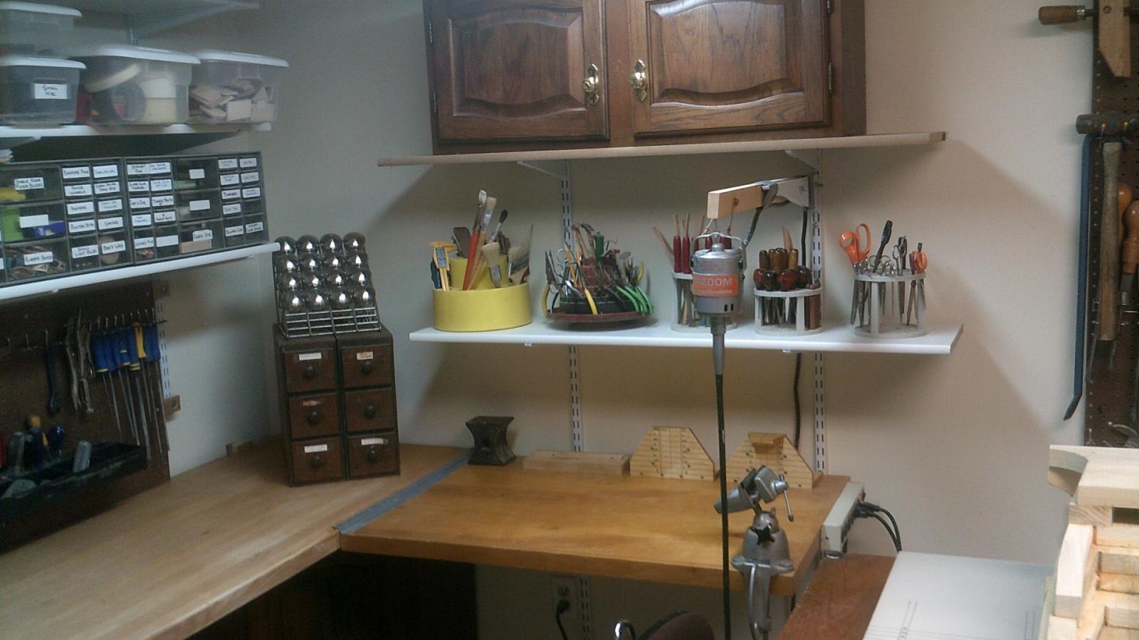
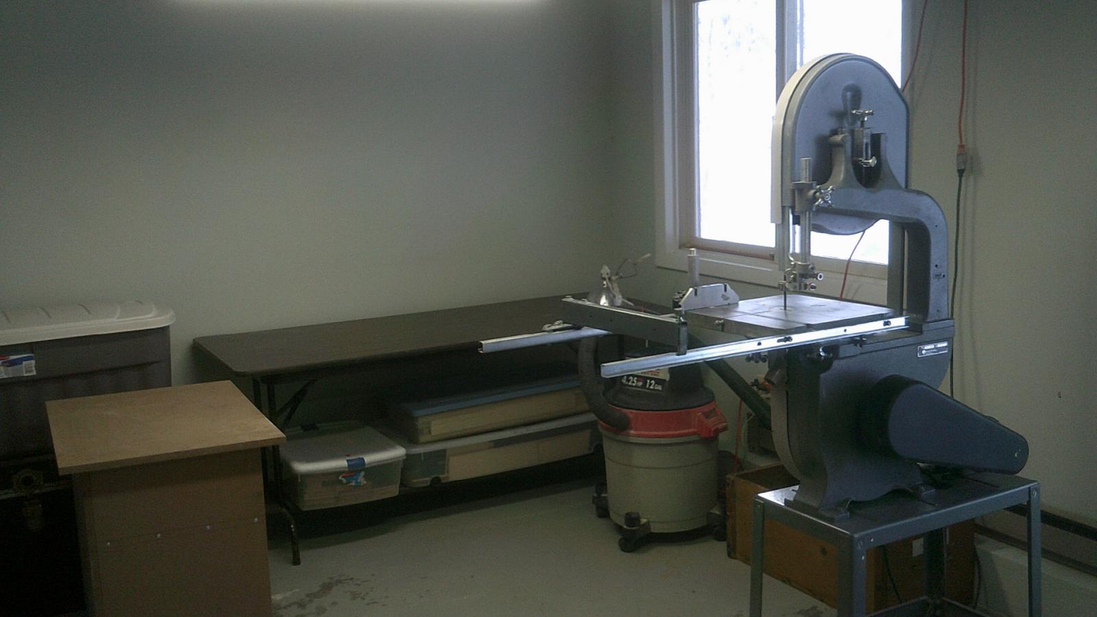
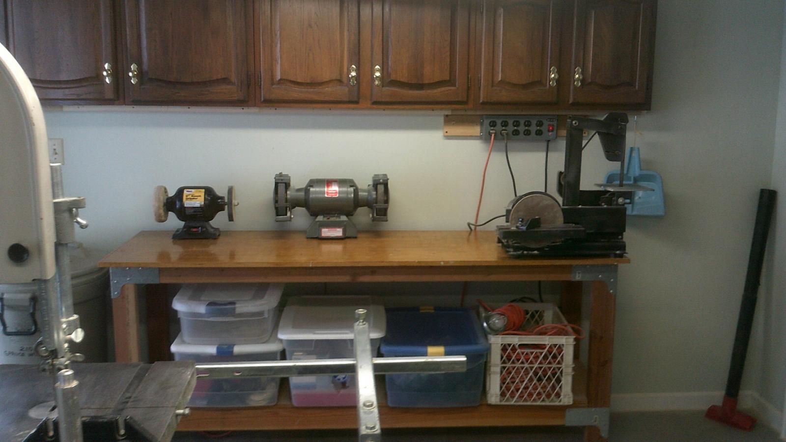
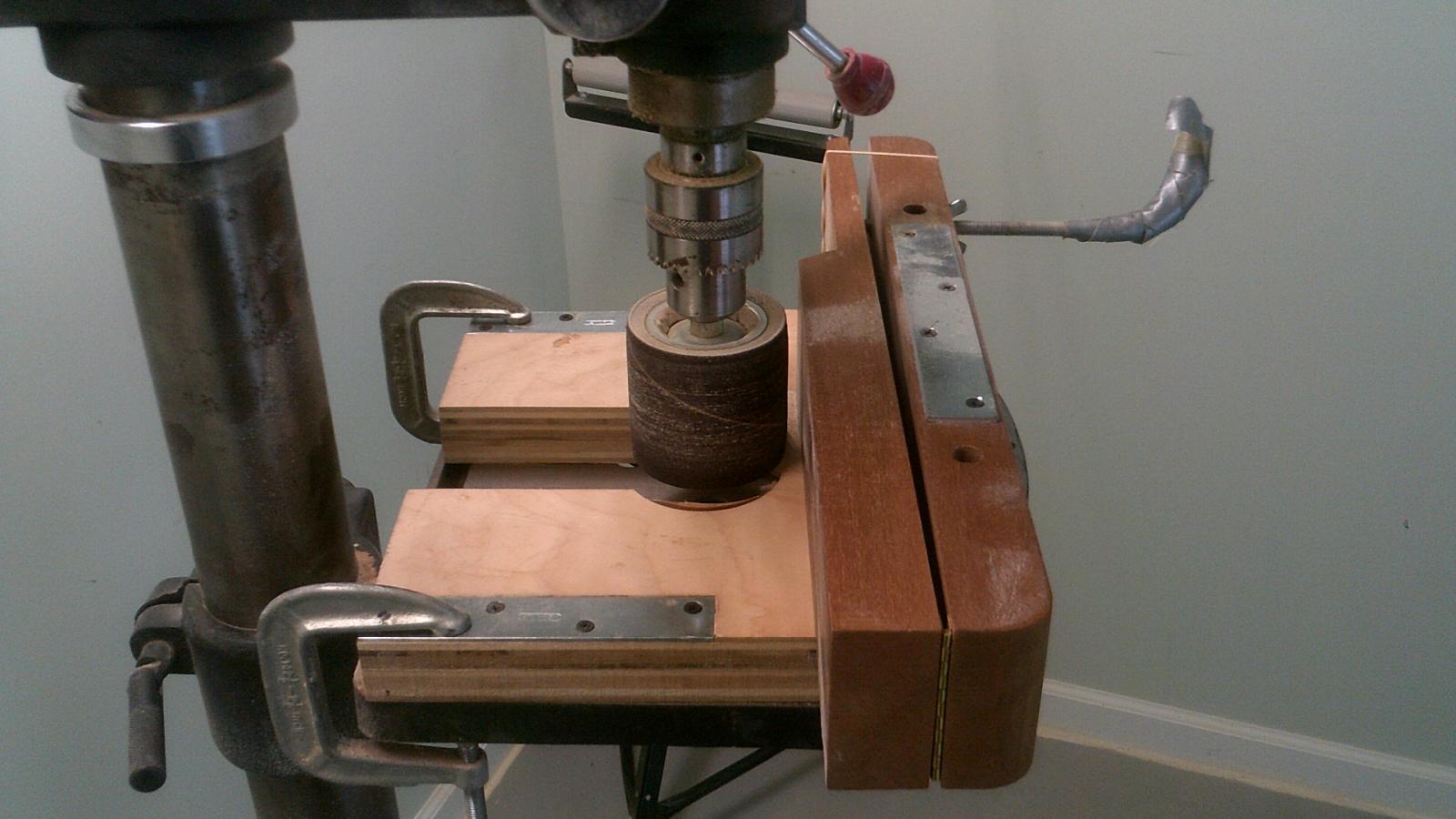
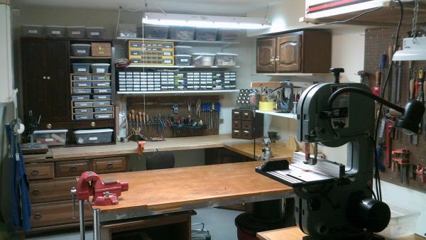
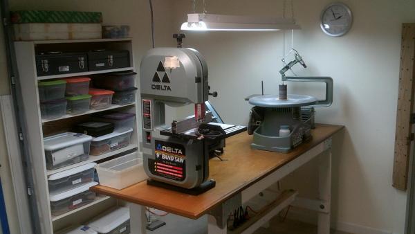
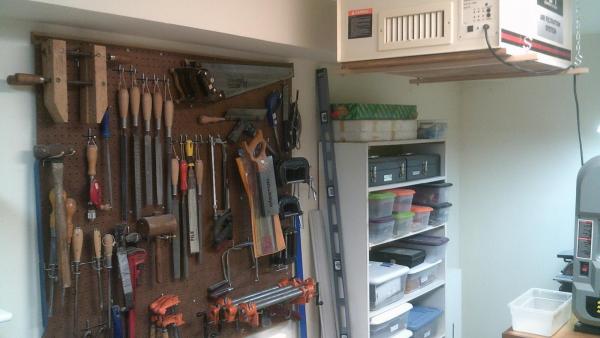
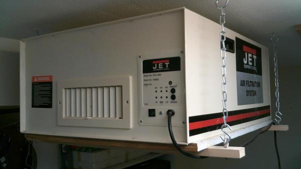
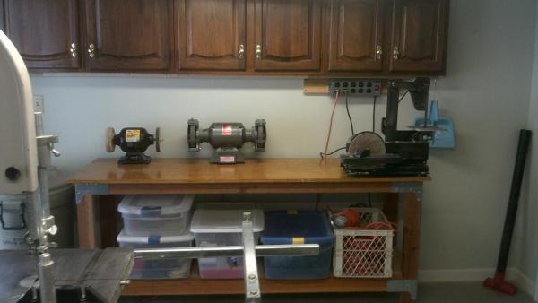
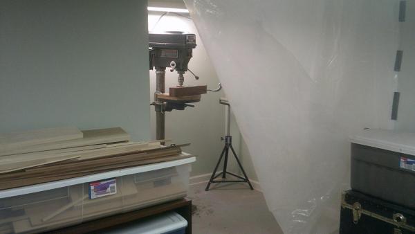
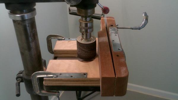
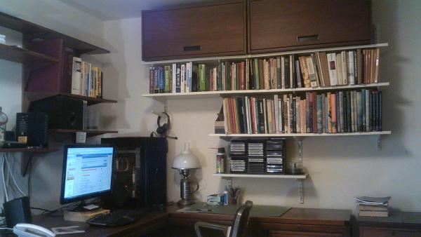
My Work Areas I'm very fortunate to have not one but two shop rooms in my condo to build my models. The front room is where I do most of the construction and the back room is where I work when I'm making tons of wood dust. Even with this back room I still need to move the Jet dust filter from the front shop when I start shaping the hull with the templates. Front Shop Back Shop When my next door neighbors decided to redo their kitchen I told them I could put their old cabinets to good use. Above photo is a closeup of the sanding drum/thickness jig I made several years back. It works quite well. Den When I'm not in my shop I spend a lot of time in this room.


-
Peter I'm not sure what you mean when you say you want to show both building methods and life on board on the same model. Tom
-
The Model Why did I choose to model HMS Camilla? Well, I wanted to make a small frigate-built ship-rigged British warship from around the time of the American Revolution. As the model is to be built to 1:48 scale (1/4"=1') it can't be too large. HMS Camilla at that scale would make a model 42" long, 32 5/8" tall and 16 5/8" wide. So that the model doesn't look stuffed into a case I will most likely add another 10-12" to its length, 6" to its height and 3-5" to its width. This would give me an approximate cased dimension for the model of 4' 4" long x 3' 4" high x 22" wide. It's large, but it's still within the limits to be acceptable. In my opinion many model builders put their finished ships into cases that are too small. When someone sees my model I want it to give them the impression it's a ship on the wide open seas, not the Ty-D-Bol man's rowboat floating in the cistern of a toilet. Another major selling point for HMS Camilla is the fact there are a number of good plans available to build from. Alex Matvijets has a wonderful set of 6 plans for one of Camilla's sister ship, HMS Sphinx. Very nice! Also there are a number of Admiralty draughts for Camilla and others in her class showing a number of different views. ZAZ4011 - views of the quarterdeck, forecastle and upper deck (dated April 1776) ZAZ4010 - lower deck and the fore & aft platforms (dated April 1776) ZAZ4009 - body plan with stern board decorations, sheer lines with inboard details and figurehead, and a longitudinal half breadth plan (dated April 1776) ZAZ3916 - generic plan of Galatea, Daphne, and Camilla done when the ship was ordered. It shows the body plan, the sheer lines, and the longitudinal half-breadth (dated December 15, 1773) ZAZ3978 - disposition of frames draught made for HMS Sphinx and HMS Vestal. (circa early 1773) While not a set of plans I am also using The Fully Framed Model, a series of four books by David Antscherl and Greg Herbert, as an important reference used for this build. Yes, Camilla was larger than the Swan class ships, but not all that much bigger. There is a ton of information I can use out of those books. When I first saw the plans for HMS Camilla I was struck by her beauty. There were just so many things that caught my eye on this mini-frigate. I love the sheer of the vessel, the way it gracefully sweeps upward fore and aft. As time went on ships started to loose this feature and flatten out. From the figurehead to the ship's lantern the hull and decks of HMS Camilla are chock full of interesting things to look at. It's visually rich. One thing I really wanted on the model was a female figurehead and decorative carvings on the stern and around the quarter galleries. HMS Camilla has them. I love the challenge carvings present. Another thing I was looking for was a ship with boats carried amidships on skid beams. Sphinx class ships carried 3 boats and I want to build this model with two of them set on the beams and one, most likely the yawl, in the water tied to the ship just astern the quarter gallery. Ship's boats are one of those features, in my opinion, that can make or break a model's visual appeal. I suppose it's their size and complexity that grabs your eye. When they are done with care they are an exclamation mark on a model well built. Sadly, many model builders aren't as conscientious in making them as they should be, and it can be an unnecessary blemish on an otherwise nicely done model. In all the years I've been building ship models I've never done a model with a gaff rig and a loose footed mizzen course. With Camilla I'll have my first chance. Nothing sells me more on a ship than seeing someone model it well. Alex Matvijets is doing just that. He's not building Camilla but HMS Sphinx, a sister ship. Nevertheless he has an absolutely gorgeous build going, and sets the bar incredibly high for anyone wanting to follow in his footsteps. I would be very interested if any other people here in MSW have done a Sphinx class model. Speak up! What method do I want to use to build this model? Like my past several builds I want to construct this model Georgian style, where I shape the hull with one wood, in this case yellow poplar (Liriodendron tulipifera), and then plank over it with more attractive hardwoods like Castelo boxwood (Calacophylum multiflorum) and Swiss pear wood (Pyrus communis) The planks will be glued and treenailed in place. Hull construction will be done bread and butter, where eight 1" thick lifts will be glued together into the very rough shape of the vessel. A temporary keel is added next along with two 8" wide extension arms that extend horizontally from the hull. The extension arms of this rough shaped hull rest on 8" wide supports that rise vertically from the building board. The hull is actually suspended 1/16" off the surface of the board and is very secure and stable. Five pairs of adjustable keel blocks secured to the building board also help to keep it stable. There is no hull motion whatsoever in mounting it this way. The beauty of this method is that the hull remains rock solid at all times and can be removed, worked on, and then quickly set back down on the building board in the exact same place, even with your eyes closed! This is because the hull's extension arms rest flush with the outer edge of the supports. Placing the model back down on the building board can all be done by touch. After I get the hull mounted I can start shaping it. This is done with a variety of hand and power tools, along with a 24 piece set of plywood shaping templates. When I'm finished shaping the hull, drawing the disposition of frames on its surface, and cutting out all of the gunports I can then remove the extension arms from the hull and the supports from the building board. After the temporary keel is remove I can add the permanent one, the false keel, stem, cutwater and stern post. The hull will now set down on the board's surface between the keel blocks and will be secured with a different set of supports that hold the hull's stern post and cutwater. All of this will be easier to understand with the pictures further into the log. How will the model be finished? Initially I had no intention to paint the hull, but to use the hues of various wood species to show color. While this may still be the case I haven't ruled out painting certain areas of the hull. Some of the painted models I've seen here in the build logs have impressed me greatly. If I go with a variety of different woods I would highlight their natural hues with stains. The exceptions to this are the main wales, the yards and parts of the masts which are black. Because I don't use ebony wood I either paint or use Behlen's Solar-Lux jet black aniline dye on Swiss pear wood. A variety of woods will be used throughout the model, but everywhere the actual ship was painted red I will use steamed Swiss pear. That would include the bulwarks, cannon carriages, capstans, and hatches. The decks will be of either holly or hornbeam. I have not decided what finish I will use on either the boxwood or the pear wood. Suggestions are always welcome.
-
druxey, Normally I wouldn't be interested in the subject matter of this build but watching you work has changed my mind. This is an awesome little model, and I can't wait to see how it ends up. I have no doubt it will be absolutely gorgeous. Tom
- 641 replies
-
- 1
-

-
- greenwich hospital
- barge
- (and 1 more)
-
Nils, Lots of model builders in the room following your progress. Why not? It's a great build to follow. I just wish Mark would stop wiping the popcorn butter on his hands all over my sleeve! :-) Tom
- 2,625 replies
-
- 6
-
-
- kaiser wilhelm der grosse
- passenger steamer
- (and 1 more)
-
Pandora by marsalv - FINISHED - 1:52
wyz replied to marsalv's topic in - Build logs for subjects built 1751 - 1800
Marsalv, that's one sweet looking stern you're making. Tom -
The History One would think that a naval vessel that cruised the high seas 33 years of a 55 year life span, and actively participated in three separate wars, would have an interesting history. HMS Camilla certainly has that. While she was never involved in any single-ship actions where she slugged it out with an American or French foe HMS Camilla was nevertheless a real thorn in their side, capturing, alone or in the company of other British ships, over 43 vessels in her career. As a cruiser she was a very successful ship, and no doubt made her officers and crew a pretty penny in prize money. Her involvement in the American Revolution went well beyond just cruising up and down the North American coastline nabbing merchant vessels and privateers. HMS Camilla also participated in a number of the war's most notable campaigns. - When Philadelphia fell to the British in 1777 a number of American vessels were caught between the city and a British fleet that had moved up the Delaware River. In a desperate move the Americans launched three fireships. Their plan was to not only set ships aflame but also to scatter or force the other ships to retreat enough to allow the American ships to escape. Canon fire from the HMS Camilla and the HMS Roebuck forced the crews to set their vessel on fire too early. This allowed the British to lower boats and tow the fireships to shore. - In May 1779 HMS Camilla was part of the fleet that transported General Clinton and 6000 troops up the Hudson River to capture Stoney Point, a lightly defended position 35 miles north of New York. It was all part of a strategy to lure General Washington away from his strong positions in northern New Jersey and West Point, New York. Clinton wanted to engage and decisively defeat Washington in a set-piece battle on the plains of the Hudson Valley. After Stony Point's capture the British beefed up the tiny fort's defense and, with the help of Camilla's crew, hauled up a number of cannon to the elevated location. This allowed the British to fire down on Fort Lafayette, an American position that defended Kings Ferry. It was a critical communication and supply link between New England and the western frontier, so control of it had great strategic importance. - When Washington didn't take the bait and stayed put General Clinton hatched another plan he hoped would get him to move. From Stony Point he dispatched Major General William Tryon with 2,600 of his 6,000 troops to raid towns along the Connecticut coastline. Knowing that Washington would have to come to their aid General Clinton amassed a large force in Mamaroneck, New York to go after him. HMS Camilla was one of Admiral Collier's ships to transport Tryon's force back down the Hudson river to the staging area in New York. Camilla was then assigned to be part of the raid on the Connecticut towns. The crew of HMS Camilla helped to disembark and embark Tryon's troops and field artillery pieces in raids on New Haven, Fairfield, and Norwalk. It was exciting to learn about this because at some time in my life I lived in or very near all of these towns. - By the summer of 1779 Massachusetts was virtually independent, with no British forces in the commonwealth. When the British sent 700 men and 3 small warships to Penobscot Bay (in what is now Maine) to establish a base from which they could project power and control the coast Massachusetts reacted. The commonwealth, with some aid from the continental congress, sent a huge expedition of 19 warships and 25 transport ships to dislodge the British force. The Americans landed their army ashore but their efforts to take the fort failed. A siege and stalemate developed. From the beginning there was a complete lack of coordination between Solomon Lovell, general of the land forces and Commander Dudley Saltonstall who led the American fleet. Saltonstall's timidity and ineptitude prevented a successful assault on the tiny fort. The British were eventually able to get word to Admiral Collier in New York of their situation and a fleet of 10 British warships was then sent to help. When they arrived at Penobscot Bay a battle ensued. Some American ships were captured, some run aground, and the rest set afire by their crews. Forty three of forty four ships in the expedition were lost, making it the worst naval disaster of the American Revolution. HMS Camilla was one of the ships in the British fleet. - When the British strategic focus shifted to the southern colonies in 1780 an assault on Charleston, South Carolina was inevitable. An attack on the city started in March and once again HMS Camilla was one of the ships in the invading British fleet. On May 12, 1780 American general Benjamin Lincoln surrendered along with 5000 of his troops. Several large warships were also captured. - Even during peacetime interesting things happened to HMS Camilla. In March 1783, with a newly promoted captain, Camilla was recommissioned. She sailed for Jamaica in May and while on station there a mutiny occurred. The crew refused to sail because smallpox had killed several men, worsening a shortage of seamen on an already undermanned ship. They felt there would be too few men to sail the vessel if they were to encounter a squall or hurricane. Five ringleaders of the mutiny received 800 lashes. I can only surmise a punishment of that magnitude would be a death sentence. - HMS Camilla was also part of the Walcheren Campaign, an unsuccessful expedition to the Netherlands in 1809 to open another front in the Austrian Empire's struggle with France. The ship helped in transporting troops and horses. A sizeable force of 40,000 men was landed but heavy losses from sickness brought it to a premature end. - The last 22 years HMS Camilla was in service were rather uneventful. She was tied up in ordinary in 1809. For a short period she was used as a floating breakwater. She also served as a receiving ship for 11 years. HMS Camilla was eventually sunk as a permanent breakwater in 1831, an undignified end to a ship that served her country long and well.
-
Christian, I agree. Alex's plans will be nice to work to. Also Admiralty plan ZAZ4009 which shows the body plan with stern board decoration, sheer lines with inboard detail and figurehead, and longitudinal half-breadth for Camilla; and ZAZ3978 a disposition of frames drawing for HMS Sphinx and HMS Vestal. I'd like to know why he has swivel gun mounts on his drawings. Do you think he's uncovered something in the ship's logs, or is this, as I mentioned in my post, something at a captain's discretion. Maybe I'll write and ask him. Christian, how is it you know of Alex's draughts? Did you build a model of the HMS Sphinx? Tom
-
Hi Matti, It would be a gross understatement to say you're building the Clara May fast. Fired bullets travel slower! Yes, you do need a more complex and demanding project. It's awfully difficult for us to recommend plans when we don't know what subject matter "lights your fire", nor do we know what style of construction you wish to employ for such a build. (solid hull block, bread and butter construction, plank on bulkhead, extensively modified kit or the different styles of plank on frame) How do you want to construct the hull? How big a challenge are you up for? Clipper ship? 74 gun ship-of-the-line? We can help you better if you could give us more information to work with. ;-) What I might do first is go to the completed models gallery in the MSW site, both scratch builds and kits, and see if any particular ship model strikes your eye. Go from there. As for ship's plans, well, there used to be an old man named Abe Taubman who lived in the Williamsburg section of New York City who put together a very large catalog of ships plans. He died several years back and the rights to his catalog are now with LoyalHanna Dockyard. I warn you those catalogs are pricey, but they sure do have a ton of ship plans. Tom
-
Hi Christian, Yes, I sure do know of Alex Matvijets' set of draughts for HMS Sphinx. I have them in both 1:64 scale and 1:48 scale. They're wonderful, and so too is his model .... a 1st class build! Tom
-
Welcome aboard Mark, druxey, Sal, Peter, Christian and Greg. We're filling out the crew nicely. I appreciate your best wishes. It should be fun sailing with you guys. Tom
-
The Ship HMS Camilla was a Royal Navy 20 gun sixth rate post ship, the 4th launched of 10 in the Sphinx class. To paraphrase Wikipedia a post ship was a designation used in the Royal Navy in the second half of the 18th century to describe a sixth rate ship that was smaller than a frigate. After 1750 the Admiralty criteria for defining a frigate was that it needed to carry at least 28 carriage mounted guns. This would include carriage guns mounted on the quarterdeck and forecastle too. Because Camilla was a rated ship, one with at least 20 guns, the vessel was to have as its senior commanding officer a post captain. A smaller ship, like a brig, might have a lieutenant as its "captain". The term post captain, or posted captain refers to an officer who not only holds the official rank of captain but one who also has been given command of a ship. When this happened to a captain his name was "posted" in the London Gazette. While sea officers often referred to post ships as frigates the Admiralty was far stricter and more precise in how they described them. They were however frigate-built, meaning they had quarterdecks and forecastles, but unlike true frigates, they didn't have carriage guns on those decks, at least not initially, and they lacked an orlop platform amidships. "Post ship" in itself implies nothing as it regards to the rig of the vessel, however, all sixth rates were in practice ship-rigged, that is square-rigged on three masts. Ordered on April 15, 1773 Camilla was laid down in May the following year at Chatham Dockyard. Two years later on April 20, 1776 the ship was launched, and 3 months after that she was completed. HMS Camilla's service life spanned 55 years. She served not only in the American Revolution but the French Revolutionary War and the Napoleonic Wars as well. In March 1831 Camilla, now a tired old hulk, was sold out of service. The ship was designed by Sir John Williams, a master shipwright at Chatham Dockyard who eventually took over the prestigious position of Surveyor of the Navy when Sir Thomas Slade died in 1771. While Williams may have been competent in his field he was always in the shadow of Slade, widely regarded as the greatest English warship designer of the 18th century. By the early 1770's old age was taking its toll on Williams as both his overall energy level and his mental acuity were waning. Many Williams designs were little more than slight changes to similar looking Slade designs, and too often the alterations made produced ships with comparatively inferior sailing qualities. History has not treated Williams kindly as his physical and mental health were not up to the rigor and responsibilities the Surveyor of the Navy position demanded of him. Also he steadfastly resisted change and wasn't as innovative as either his predecessor or his successor. So, how was Williams' Sphinx class design? Well, it's said the post ships were seaworthy but their high center of gravity made them slow and not all that weatherly. HMS Camilla was a relatively small vessel, one of 432 56/94 burthen tons. It measured 108' 1 1/2" between perpendiculars, 29' 7" moulded breadth, 30' 1" extreme breadth, and 9' 8" depth of hold. Up until 1794 the complement was 140 men, but was reduced to 134 men after that date. On the upper deck the ship carried as her main armament 20 nine-pounder cannon. When launched Camilla was not armed with any carriage guns on either the forecastle or quarterdeck, but this changed in 1794 when 6 24-pounder carronades were added. (2 to the forecastle and 4 to the quarterdeck) Strangely there are no swivel canon mounts on any Admiralty draught of Camilla or any other Sphinx class ship except one. There is a profile view of HMS Vestal that shows them. I found that odd because his drawings of Swan class ships (16 guns), Porcupine class (24 guns) and Enterprise class (28 guns) all show swivel gun mounts. Why would they be on some of his draughts and not on others? I was always under the impression that swivel cannons, by virtue of them not being carriage mounted, were not officially listed as part of the ship's armament. Their use, the number of and the location of was something at the captain's discretion. Any thoughts? Right now Captain Wyzwyk is leaning toward 12 swivel cannon mounts, 4 on each side of the quarterdeck and 2 on each side of the forecastle.
-
Hi SalD Toby was never physically hurt during the Camilla II accident. Maybe his feelings were hurt a bit with all the expletives I directed towards him after I saw what happened. Yes, he's still allowed in the shop, but I am far more mindful of where he is and what he's doing. I'm also more careful about what I work on when he's there. Sal, you might want to rethink the chain. The last time someone used it their butt hurt for a week. LOL Tom
-
Thank you Mark and druxey. It feels good to be back in the shop again. Tom
-
Prologue In all my years of building model ships I have never experienced the difficulty of keeping a project afloat as much as I have with HMS Camilla. This log marks my third attempt to construct a model of this vessel. It's been a full seven months since the 4th of July accident that did irreparable damage to Camilla II, so I think it's time to bring everyone up to speed on where I'm at. As stated earlier I purchased and had milled some really beautiful boards of kiln dried yellow poplar back in August. Since wood is hydroscopic, expanding and contracting with changes in atmospheric humidity, I wanted to air dry the lumber a few more months in the shop environment to insure its stability before starting the build. Unfortunately the project was delayed even longer when my shop dust filter conked out on me. Having air filtration is of paramount importance, especially if you're building, as I am, a large scale bread and butter construction hull. Without one the dust would find its way all throughout my condo and make me and my dog absolutely miserable. Toby is especially bothered by the wood dust. To say the hull shaping process produces copious quantities of dust is a gross understatement. There was no way I was going to work without an air filter so the project was temporarily put on hold. When Santa brought me a new Jet air cleaner for Christmas Camilla III was finally started. I've been a busy beaver since then; constructing a new building board, making a much improve set of plywood hull shaping templates, and starting work on the hull. Yes, the new build is underway! Because I foolishly had Chuck Pasaro, the MSW site administrator, remove the Camilla log after the July 4 accident I'm now saddled with the task of doing it anew. Initially I had planned to make my first post only when I was beyond the point where I was at when I had that mishap, but a problem I encountered this past week has forced me to rethink this idea. My computer, where I store all my build log photos, crashed on me. When that happened I had to work hard to get the machine up and running again. It scared me. I had only 40 pictures of the new start but these could have been easily lost. Because the material wasn't backed up I thought maybe I shouldn't wait any longer to post the images I have to the MSW build log site. This week I will be doing just that. Please forgive me if you've seen much of this material before, but know that I'm actively working on the model and will have posts containing new stuff in the not too distant future. Build logs are all different, as each model builder has his/her own style. Because I most enjoy build logs where construction steps and modelling techniques are clearly and fully explained, and ones where there are lots and lots of photos, I too will do mine in this fashion. That means my log won't automatically assume the viewers have a lot of knowledge on a particular subject, and that sometimes basic things will be covered. More experienced builders will no doubt find some of the material I will talk about or show pictures of old hat, or just plain elementary. To those model builders, of which there are quite a number, I ask that you bear with me when this happens. At least keep the laughter and snickers to a low decibel level. ;-) In many ways my build log is geared toward a neophyte scratch builder, especially one who might be interested in trying a bread and butter construction for the first time. Over the years I've developed a method that's proved very successful for me, albeit one that's quite messy and a bit more labor-intensive. In this build log I welcome any and all comments, from effusive praise to biting criticism. If you have a question I'll do my best to answer it. When I employ a technique and you feel there's a better way please speak up. Your suggestions will always be welcome. And if all you want is some good-humored banter, well, I'm up for that too. You can say anything that's on your mind, providing it's not an infraction in Chuck's rule book ;-) I'm not thin-skinned so you never have to worry about hurting my feelings. These MSW build logs have become, for me, a wonderful window into the model shipbuilding community. They truly make the world a bit smaller by bringing us all together. Seven months ago I followed very few builds, maybe 3 or 4 at most. Today I must be up to a couple dozen, and the number continues to grow. I immensely enjoy your build logs. Perhaps you too will enjoy mine. Tom And yes, third time's a charm!
-
HMS Naiad 1797 by albert - FINISHED - 1/48
wyz replied to albert's topic in - Build logs for subjects built 1751 - 1800
Albert. this is a first rate build you have going. Everything about this model is so clean and precise. Some day I too would like to do a POF construction. It will eventually happen, but I suspect I would have to work very long and hard for it to be even a fraction as nice as your Naiad. Be proud of your joinery. It's gorgeous! Tom -
Interesting choice Bob, and a build I will surely follow. My guess is you went to the eye doctor to get the A-OK before deciding on the scale. There is no way I could work on a 1:200 scale model. Just thinking about the Pequot's size has me squinting. LOL edit: I went further in the log and saw you changed to 1:96 scale. Good choice, and your eyes will thank you! Tom
- 348 replies
-
- 4
-
-
- pequot
- cable ship
- (and 1 more)
-
Cutter Cheerful 1806 by rafine - FINISHED
wyz replied to rafine's topic in - Build logs for subjects built 1801 - 1850
Bob, it doesn't matter what you touch .... it all turns to gold. Really sweet looking! Tom- 525 replies
-
- 6
-
-
- cheerful
- Syren Ship Model Company
- (and 1 more)
-
Pandora by marsalv - FINISHED - 1:52
wyz replied to marsalv's topic in - Build logs for subjects built 1751 - 1800
Marsalv My mistake. Please forget what I asked. I went back and looked at the pics and then edited out that question from the post. What was I thinking??? I have two good eyes but I still can't see. ;-)