ccoyle
-
Posts
10,575 -
Joined
-
Last visited
Content Type
Profiles
Forums
Gallery
Events
Everything posted by ccoyle
-
 I kinda doubt that. In all my years of building card models, I've seen very few reprints, if any. Usually the print run sells out, and that's that. A more likely possibility, though still uncommon, is that Avangard may offer the corrected part in either a future kit or as a downloadable file.
 -
And this week's mystery kit part is...........
ccoyle replied to MacBeagle's topic in Wood ship model kits
The pain-in-the-butt part about cast metal boom jaw rests is that they are typically molded for perfectly vertical masts, and woe to you if your model has raked masts! -
The key to getting a halfway-presentable wing fillet is to do as much of the shaping as possible off the model.


- 94 replies
-
- 11
-

-
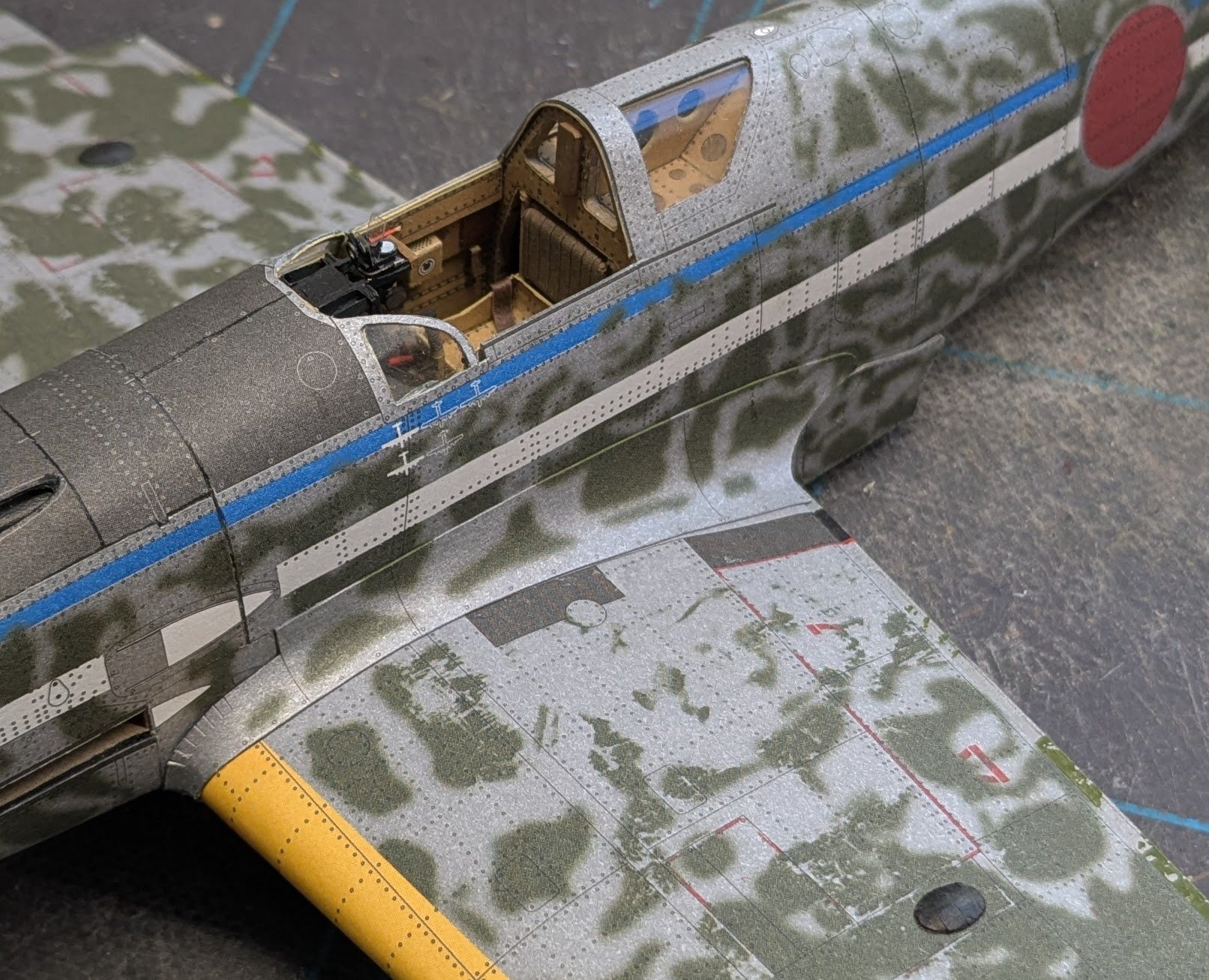
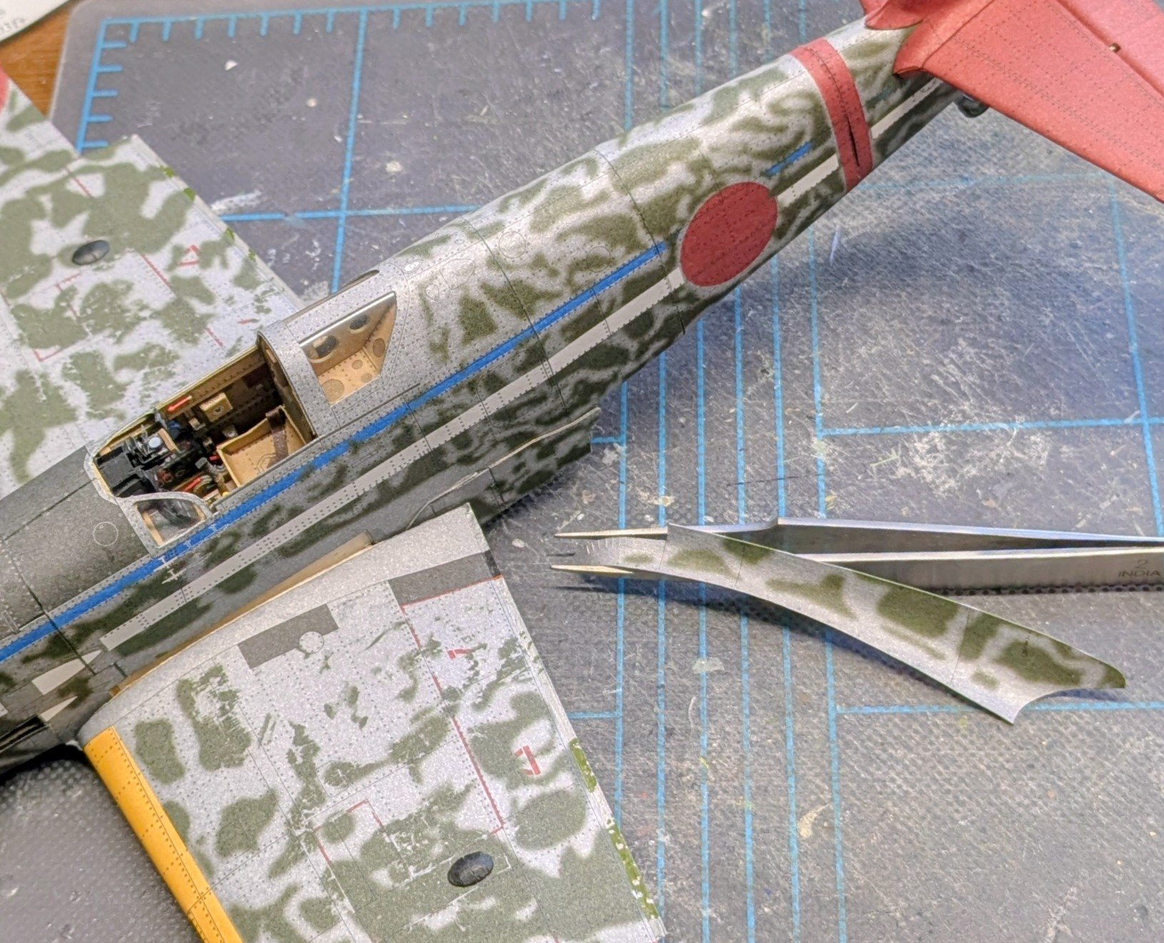
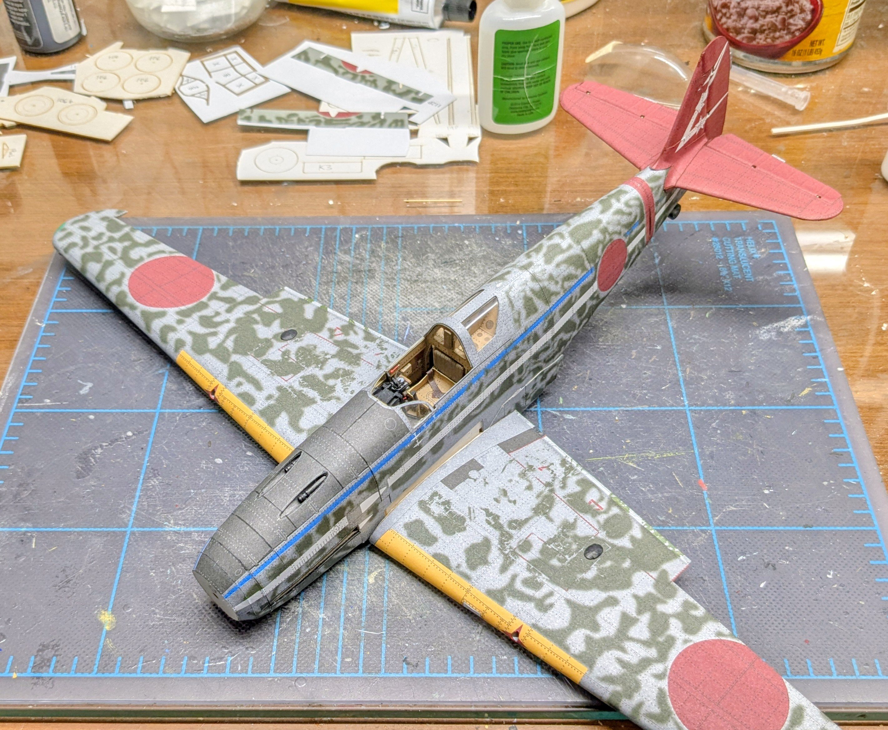
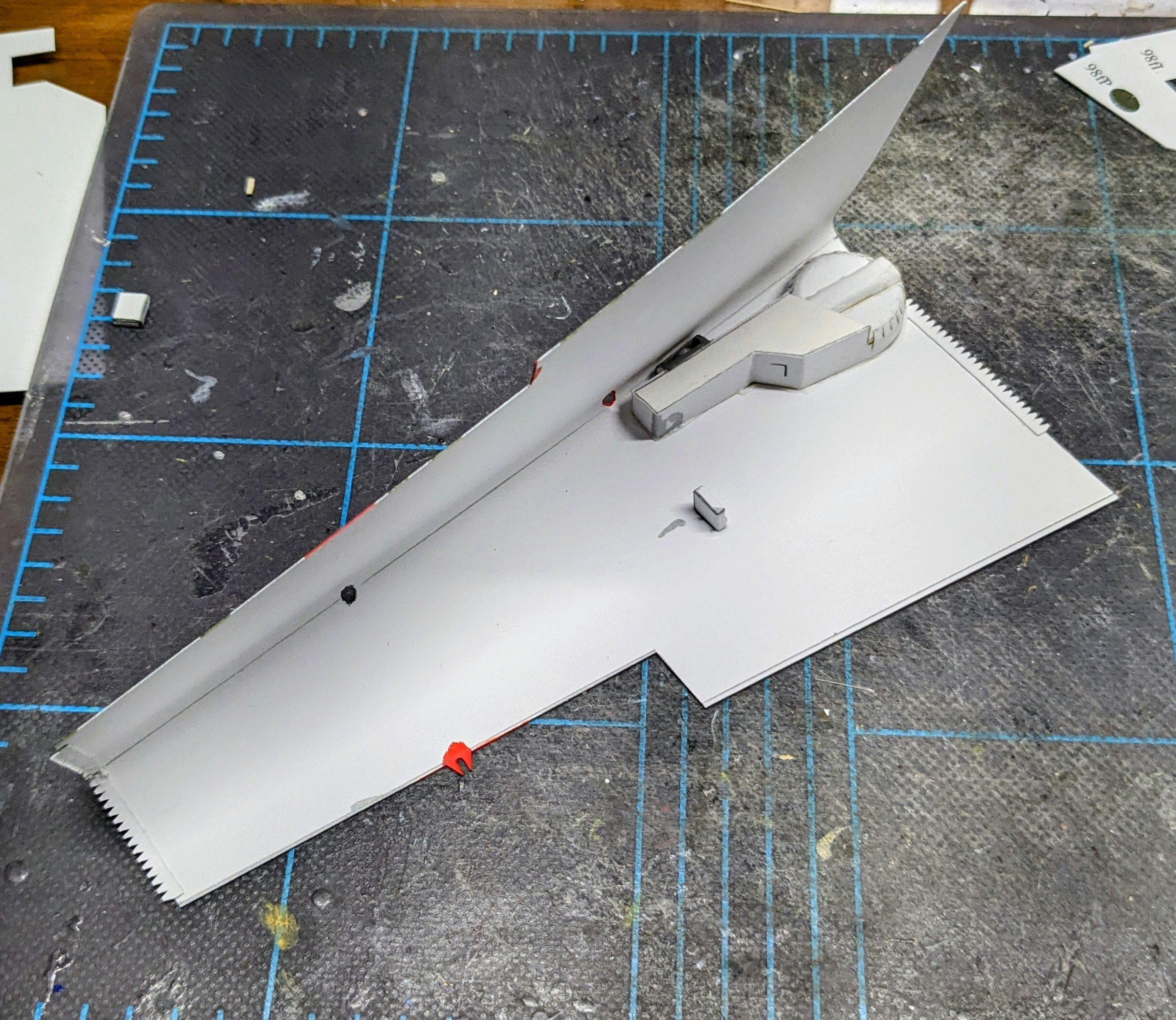
You are not looking hard enough, but thanks anyway! The right wing is now skinned as well. Interestingly, I wound up about 1.5mm short of matching the flap edges again. Much as I hate to think it, I think this might be a design flaw -- it probably would not have been a factor if the flaps were displayed down instead of up. I don't see how I could have avoided the error, since the placement of the upper skin is contingent on the location of the wheel wells relative to the internal wing framing (which is why the error is the same amount on both sides). Had I done my usual technique of gluing the wells into the framing first and then adding the skins, the 1.5mm mismatch likely would have simply shifted to the region around the wheel wells. Honestly, this option was probably by far the easier cosmetic fix. Note also that the cannon breech blisters have been added. Here's a test fit of the wing and fuselage. It's quite tight -- too tight in fact. The wing will not even seat properly at the time the photo was taken. This will require only some very minor knife work to fix, so no big deal. After I took this photo I opened up the landing light port, and the light turned out to also not be seated properly. Again, don't know what I could have done to easily fix that, since the wing skin position was determined by the fit of the wheel wells inside the framing. The error is not too noticeable, thankfully. Cheers!


- 94 replies
-
- 13
-
-
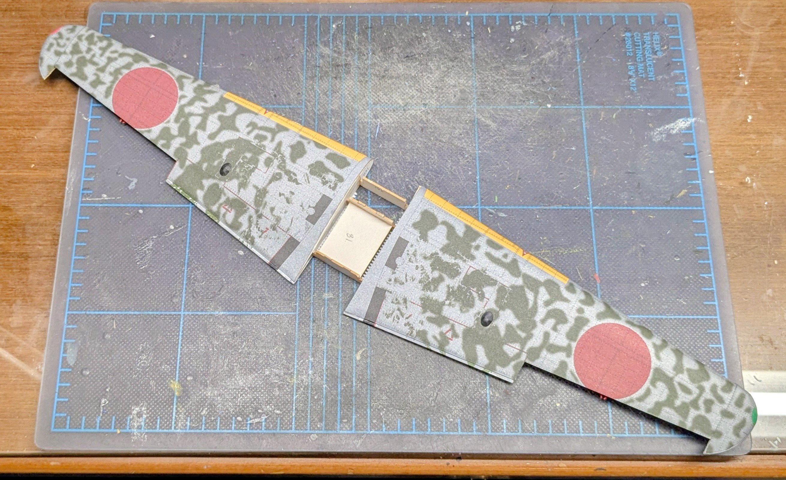
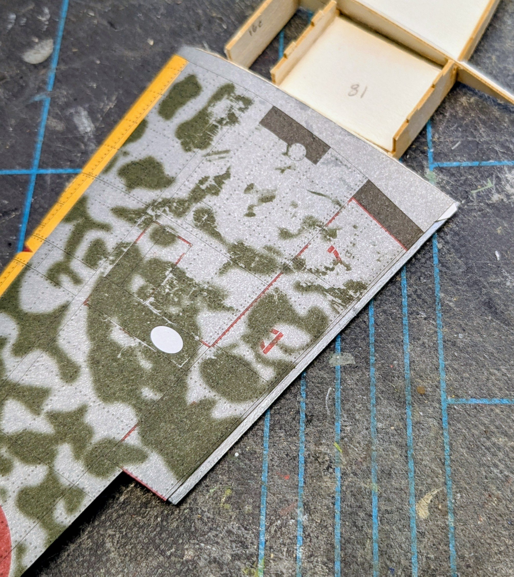
I started skinning the left wing yesterday. First I glued the framing to the lower wing skin, paying close attention to the instructions that the frames should sit 0.3mm forward of the aileron cutout and 0.7mm forward of the flap edge. Seriously? A tolerance like that is virtually impossible to measure and mark with the tools I have on hand. So I guestimated. When I was ready to glue the top side down, I discovered I could not get the flap edges to meet. Then I remembered that I had forgotten to sand the wing framing before skinning -- doh!! I was still able to do some sanding at this point, but despite all of my efforts, I could not get the edges to meet, so I decided to go with whatever result I could manage. Ultimately, the top edge came up about 1.5mm short of meeting the bottom edge. So I did some cosmetic surgery with my paint markers. The greens don't match exactly, but the idea here is to camouflage the surgery as best as possible. I have to keep in mind that this is an artistic rendering of a Ki-61 and not an actual Ki-61! Anyways, here are the before-and-after pictures: Cheers!
- 94 replies
-
- 12
-
-
Never done a coppered hull myself, but everything I can recall reading has said that the task should start at the keel and work up. Upper plates should overlap lower plates.
-
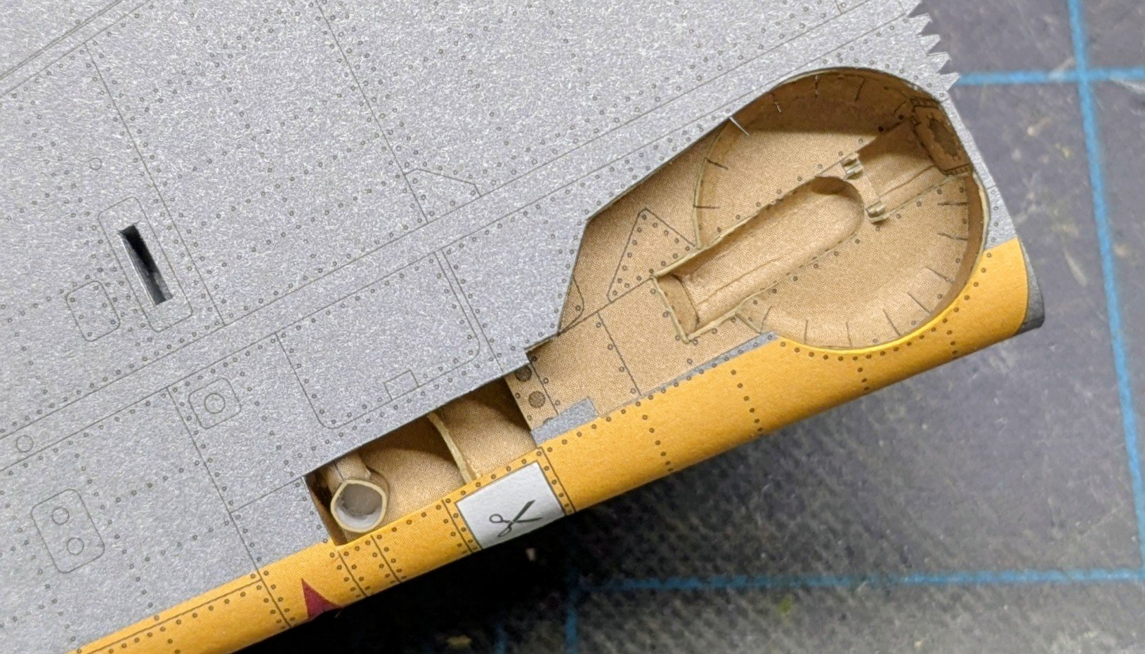
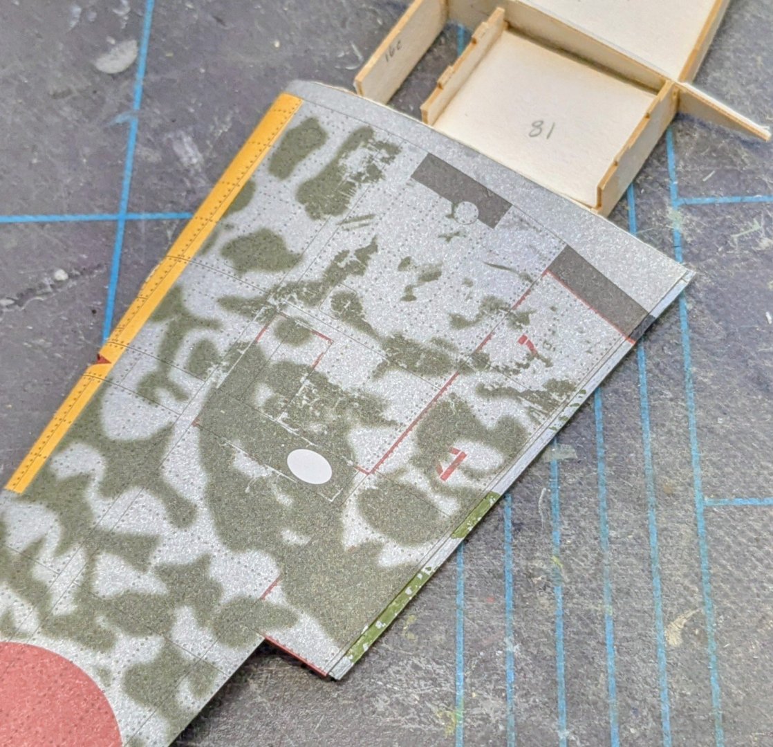
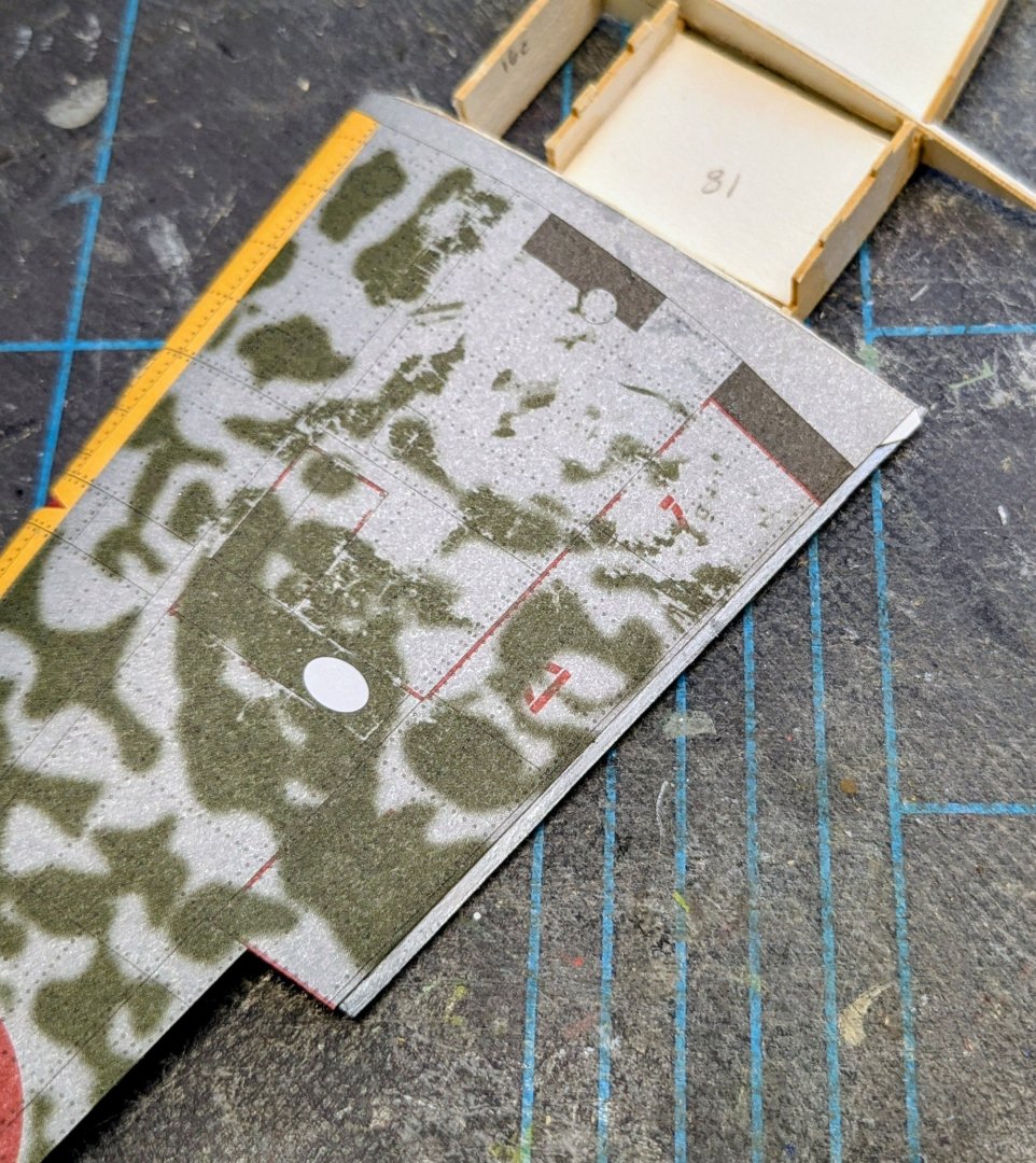
Okay, I'm trying something a little different with this model. Usually I glue the wheel wells into the wing framing and then do the skins. I've gotten some pretty unimpressive well-to-wing fits with this method. So this time I'm going to try gluing the wells to the wing skins first. I've already done this with the left wing. The risk here is that for some reason the glued well may not fit into the framing properly, however, i did a test fit and everything looks good so far. Here's the pre-folded wing skin, wheel well (with landing light), and shell casing ejection port. The opening for the landing light has not been completely cut out, because doing so would leave an extremely narrow strip of skin between the opening and the wheel well; I did some preliminary cuts around the opening but will make the final small cuts after the wing has been skinned. And here's how the well-to-wing fit looks from the outside. Looks pretty good, I think! Cheers!


- 94 replies
-
- 13
-
-

-
That's really quite a fantastic model!
-
Welcome aboard!
-
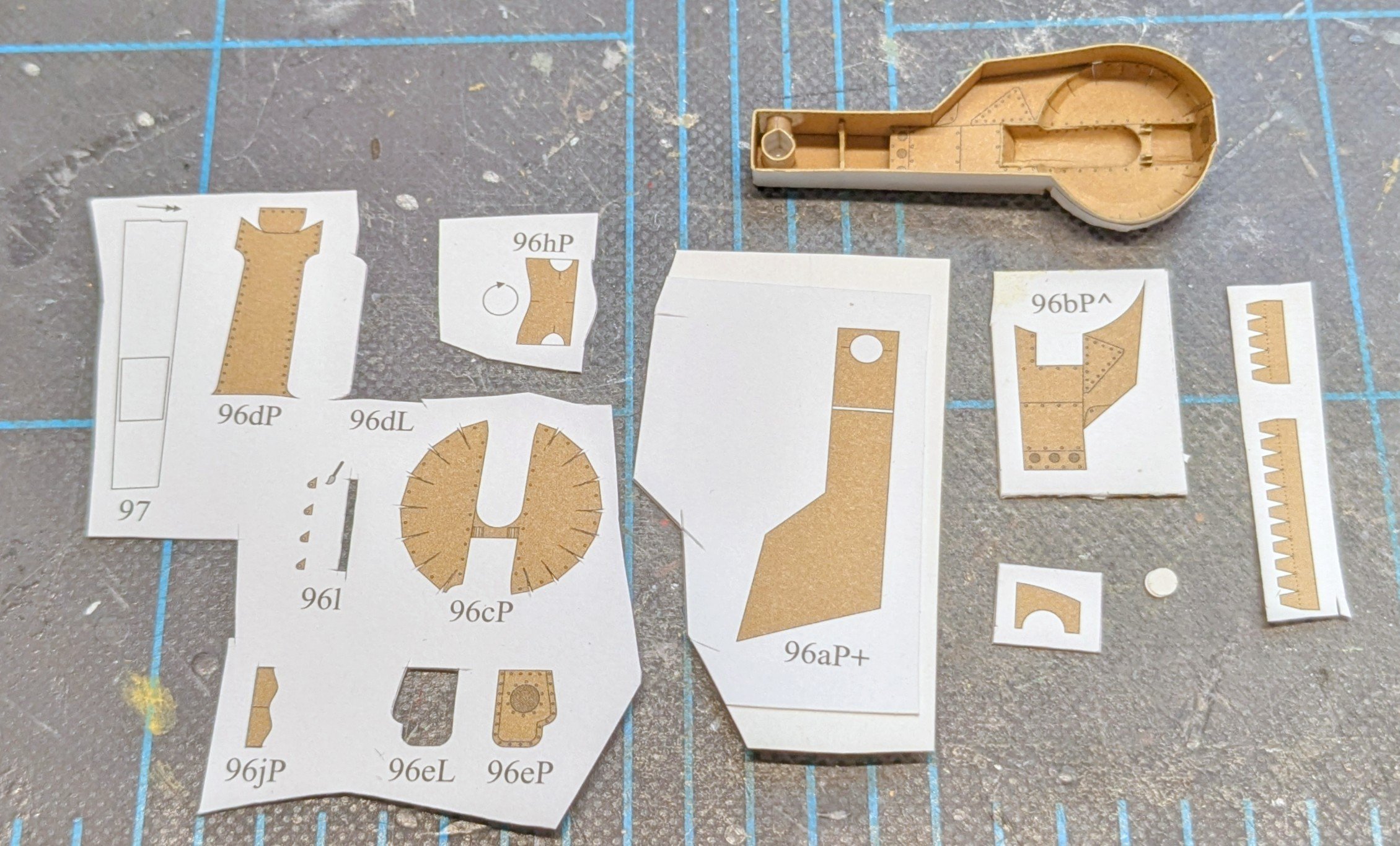
Here's the left bay completed, along with the parts for the right bay. Although time-consuming, the structure is not as difficult to build as it might look. One of my dapping tool handles has exactly the right diameter to neatly fold the petals of the actual well. Normally I dislike petal structures, but this one went off without too much hassle.

- 94 replies
-
- 10
-
-
Try cutting a scrap of strip stock to a length equal to the height of a 5'6" sailor (average height in Napoleonic era) in 1/64 scale; that works out to about 1" or 26mm. Then use your "sailor" to help judge whether the deck fittings are properly sized or not.
-
That info should be available on the plans somewhere, but if it isn't, then yes there should be some overhang on both sides.
-
It's a hawse pipe, and the black line is a fold line. The triangle is the flat, back portion of the pipe, and the rest gets a U-fold, bringing the far edge of the part back around to meet the triangle's edge on the opposite side. Had this part been used, it would, of course, have been rolled so that the color ends up on the inside of the rolled part.
-
You got it for a great price! Though I would hardly describe it as 'vintage' -- sellers do use that term far too extensively.
-
So that we don't sound completely like a Vanguard Fan Boy club (and there is no argument that Chris is on the cutting edge of kit design), allow me to toss out a couple of items for consideration: You are wise to forego Rattlesnake in favor of a simpler subject. Something with a single mast, like the aforementioned cutters or fishing vessels, is a good step up. Depending on how you feel about different kinds of hull construction other than the usual strip planking, there are some other options. One is kits with pre-spiled planking from companies like Master Korabel or Falkonet. I'm building one such kit now, MK's Phoenix. You can see what this method of construction looks like by checking my build log (link in signature). I will say up front that MK's instructions, being translated from Russian by a non-native English speaker, can be a bit torturous to decipher, but they have very good pictorial instructions as well. Another company, Shipyard, offers several wooden kits that are based on traditional card modeling methods -- they're a sort of hybrid construction method. Everything in the kit is laser-cut. I have built one of their kits, the Wütender Hund. Shipyard also includes pictorial instructions, and they are quite good. Vanguard is definitely top of the heap for strip-planked kits, but -- if you find a subject that you really like from another company, don't be entirely put off by the prospect of having to wrestle with a kit that may not have the best materials or instructions. With three completed builds under your belt and the help of the vast quantity of experience represented on MSW, you probably have the skills needed to overcome such challenges. Have fun deciding!
-
Welcome aboard!
-
Very nice work so far! My admiral would have a conniption if she found out I were planning to build something that large!
-
When you say 'resin', I assume you mean 3d-printed?
-
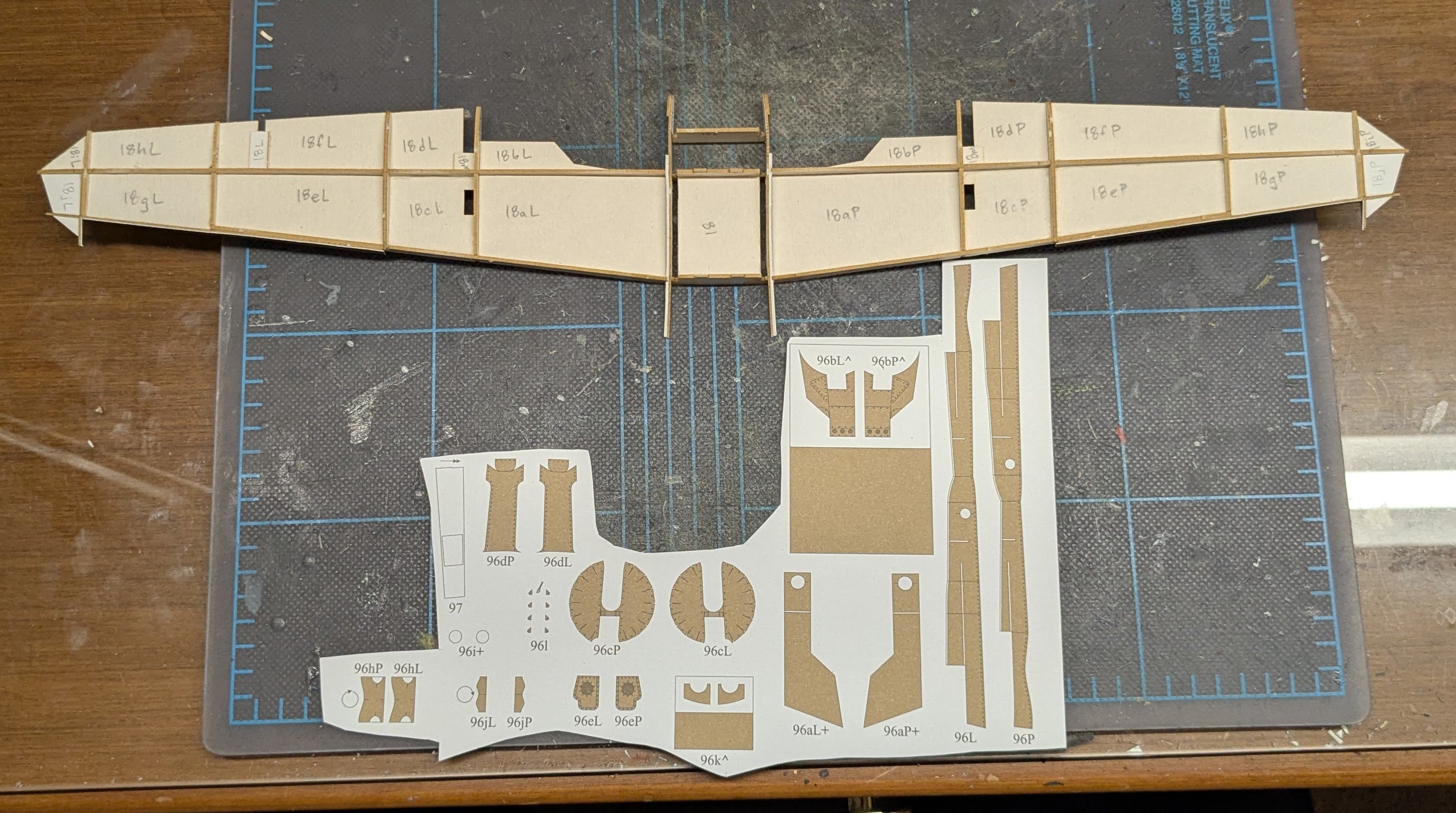
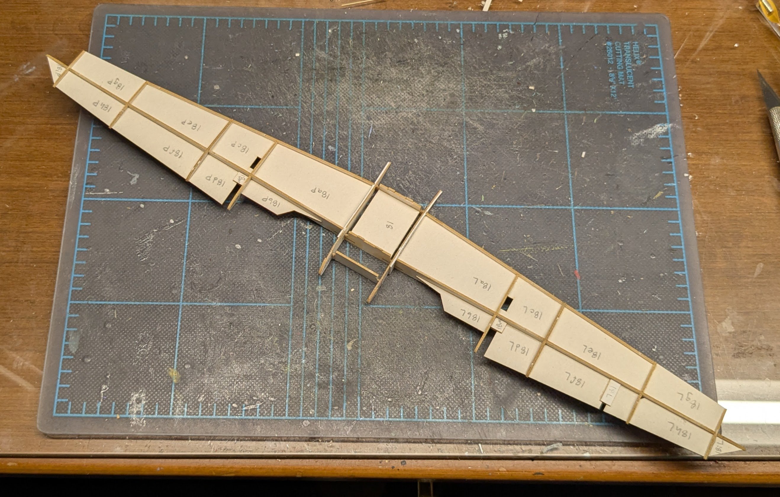
Wing framing begins. I might have had the wing framing done today except for the fact that I glued the first half-dozen parts together incorrectly and had to gently disassemble them before I could start over with attempt #2. I'm just glad I discovered the problem before I had gotten any farther! 😮

- 94 replies
-
- 17
-