ccoyle
-
Posts
10,569 -
Joined
-
Last visited
Content Type
Profiles
Forums
Gallery
Events
Everything posted by ccoyle
-
 At first I thought you were misspelling a**, but then I remembered that you're English. 😅
 -
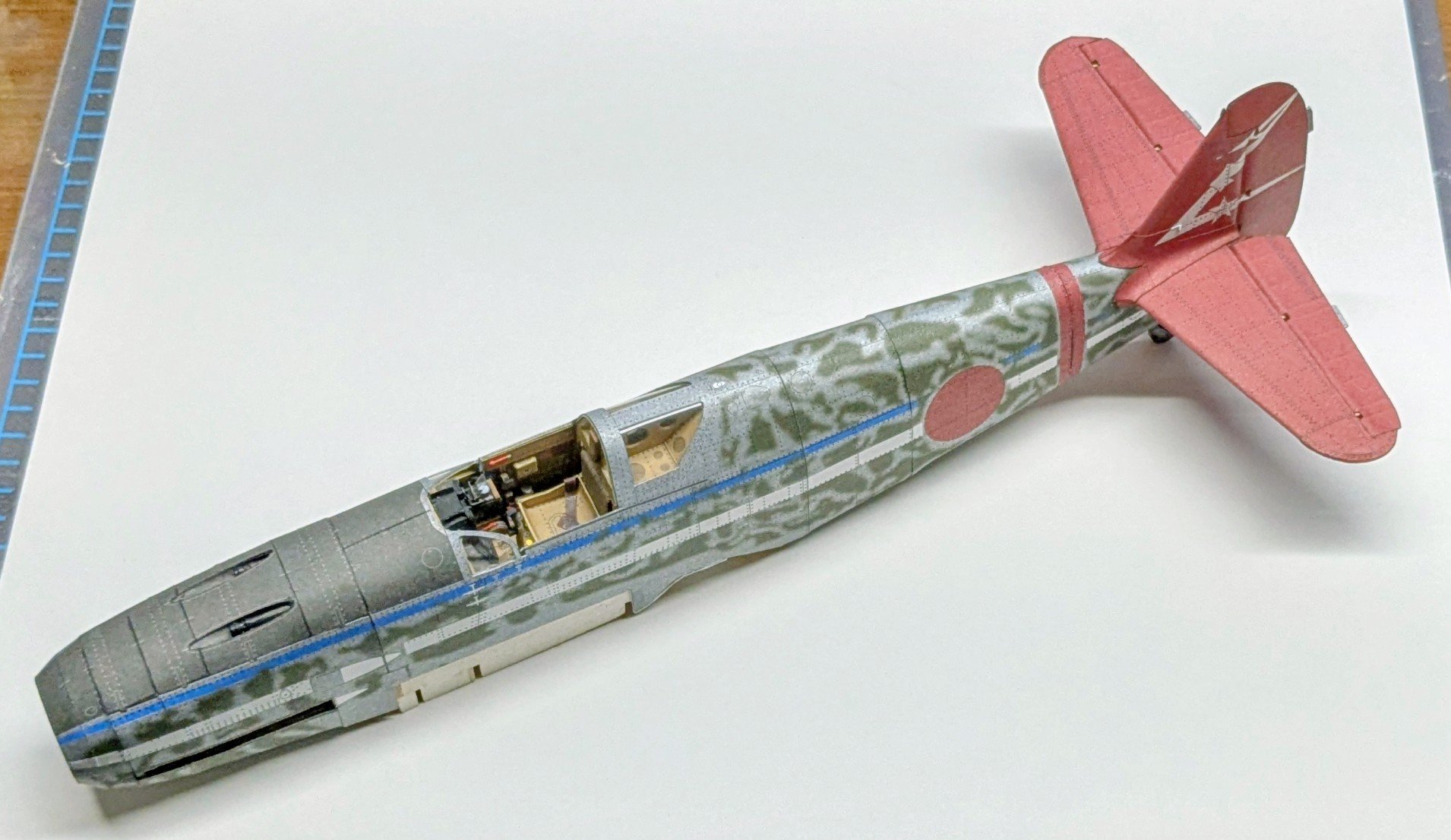
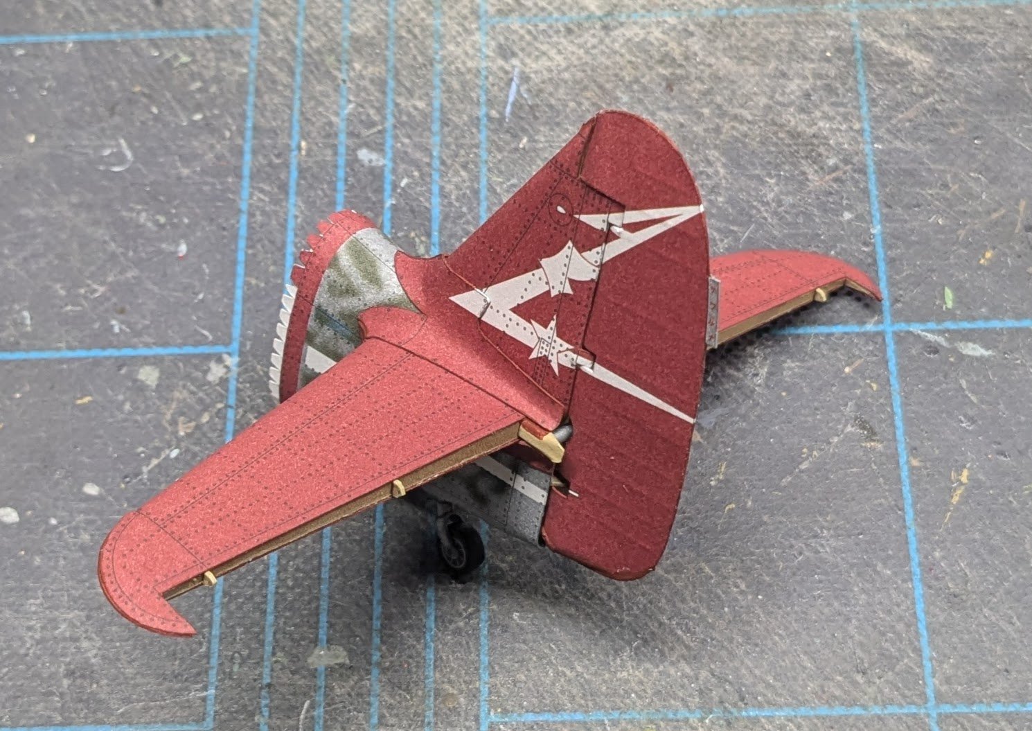
The empennage is complete. An odd thing on the Ki-61 is that the elevator and rudder actuators were linked; on the model this required six very small pieces of wire, along with the usual "special words" that such tiny parts invariably conjure. At least two attempts disappeared into the Carpet Monster.
- 90 replies
-
- 15
-

-

-
Very nice unboxing!
-
Would the correct response to that be "Perish the thought!" or "Perish -- the thought!" 🤔
-
Since it is manufactured under license, the name of the original manufacturer is appropriate. I have also tagged your log as a "first build" -- this just alerts members to modelers who can use that extra little bit of help and encouragement.
- 23 replies
-
- 2
-
-
- Lowell Grand Banks Dory
- Model Shipways
- (and 1 more)
-
Place it in the 1851-1900 section of either the scratch or kit section, as appropriate, and add " - RESTORATION" to the end of the title. You can also tag it as a restoration.
-
Planking Techniques is more a compilation of descriptions of different planking methods and not a how-to guide. The other book I'm not familiar with.
-
Welcome aboard, Alexa! A couple of observations, based on your comments: Avoid kits on platforms like Amazon, eBay, AliExpress, etc., until you have become better acquainted with what's available out there. Especially avoid kits coming from China; this is not a blanket condemnation of all Chinese kits (some are quite good), but unfortunately for right now China is a hotbed of kits that are either of very poor quality (as you have experienced), are stolen intellectual property (quite commonplace -- see the list of banned manufacturers here) or both. Of course, you already have your next project in hand, so you can just file this recommendation away for future reference. You seem to have a very good command of English, so if you can get your hands on a copy, I highly recommend the book Ship Modeling Simplified by Frank Mastini (this item you can safely purchase from Amazon, and it is available in both print and digital formats). The book is a bit dated, but it is still a very good introduction to the world of wooden model ship kits. It will suggest solutions to many of the issues you listed. ALL of us have made mistakes on our models, even the masters of the craft! It's just part of the learning curve, so don't let any fear of mistakes paralyze you into inaction. It's a hobby, so enjoy it! Cheers!
-
Condolences on the passing of your mother. It's a thoughtful gesture to dedicate your model to her.
-
Tell me you haven't tried a card model without telling me you haven't tried a card model. 😂 We take a dim view of such experts at this site. I have said this of myself many times. I feel no great urge to scratch-build something, although I greatly admire the artisanship of members who do. I just like to put things together. So, welcome aboard!
-
Good luck on your project!
-
Welcome aboard!
-
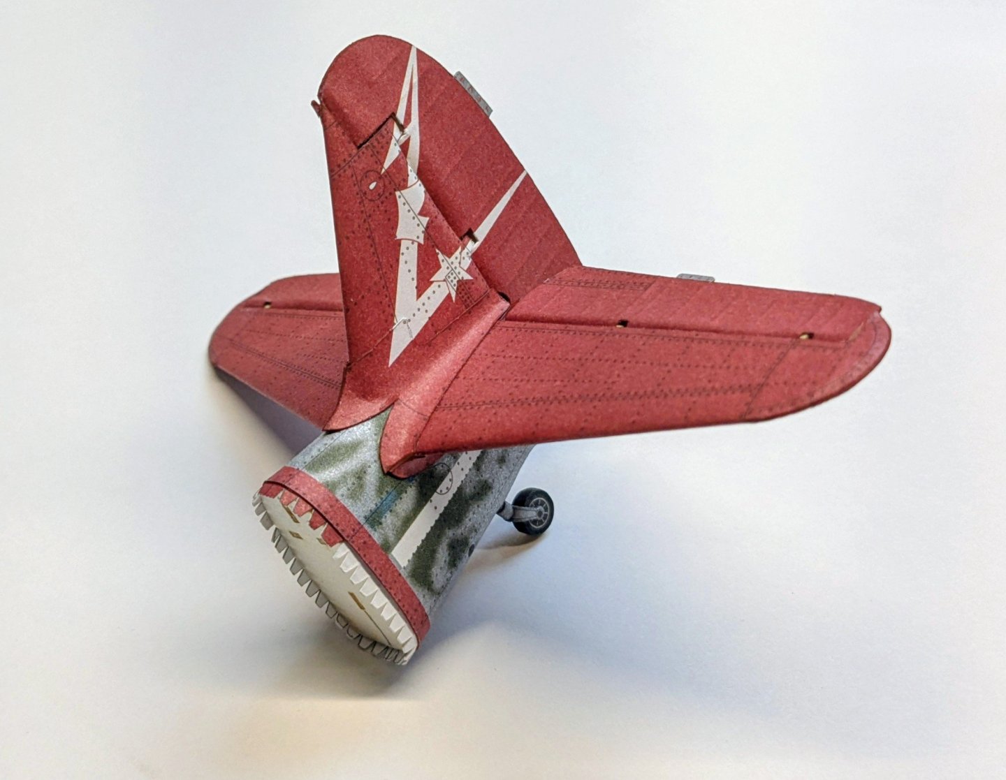
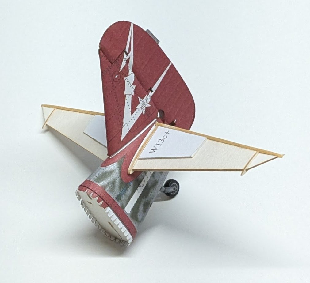
Taking a moment to check the alignment of all the stabilizers. Everything looks good so far.
- 90 replies
-
- 16
-
-
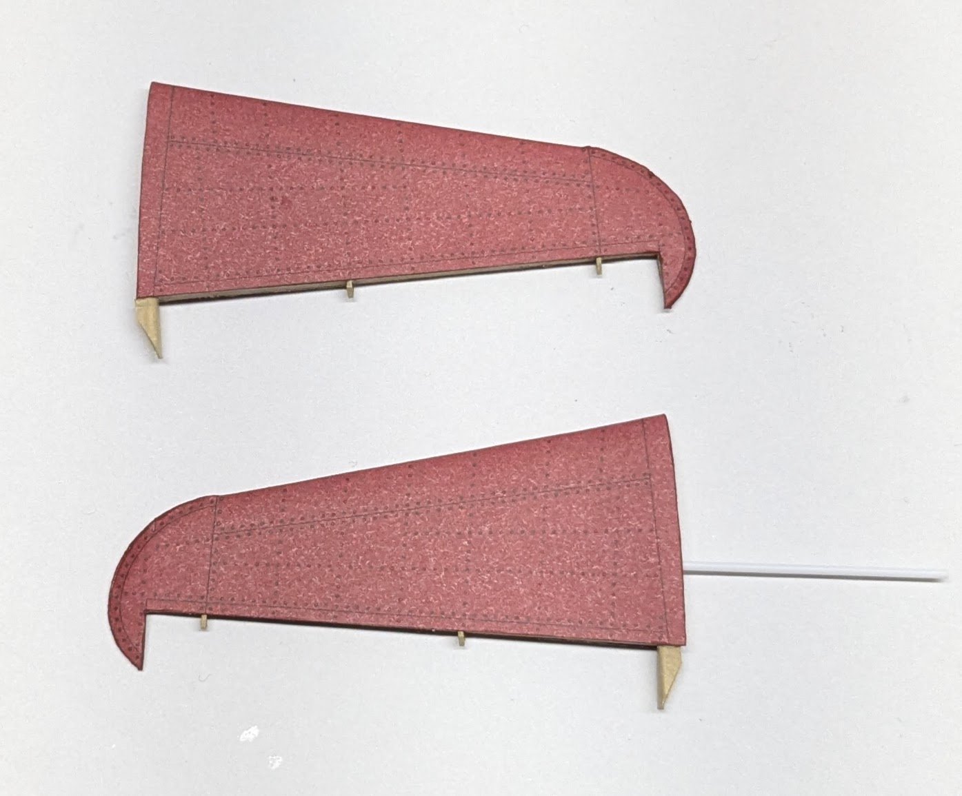
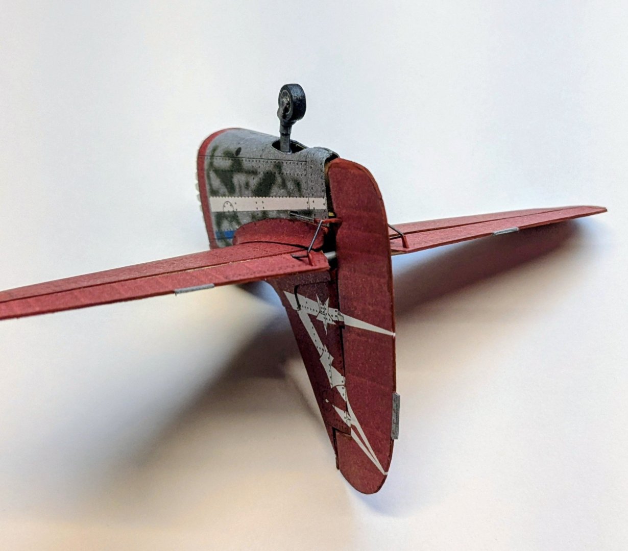
Got the tail wheel section skinned and the vertical stabilizer completed (except for a few tiny parts that I'll add later). I forgot to snap a picture of the stabilizer framing, which in typical Halinski fashion was quite robust.

- 90 replies
-
- 15
-
-
Congratulations! There's nothing dishonorable about presenting your subject as a hull model -- this is a not uncommon stylistic choice. Cheers!
-
6 mm works out to a little over 11" in 1/48 scale -- I suspect this is too large for your model, but to be certain you'd need to get hold of the actual block sizes for Alma. That would take some digging.
- 48 replies
-
- 2
-
-
- San Francisco Bay Scow Schooner
- Scow Scooner
- (and 1 more)
-
Check BlueJacket, though theirs will be metal.
- 48 replies
-
- 1
-
-
- San Francisco Bay Scow Schooner
- Scow Scooner
- (and 1 more)
-
Understandable, but just know that the Syren blocks will not be period-correct -- if Alma is representative of the type, scow schooners were rigged with internally-stropped blocks.
- 48 replies
-
- 1
-
-
- San Francisco Bay Scow Schooner
- Scow Scooner
- (and 1 more)
-
Well, the fiddly tail wheel bits are done, so now I can move on to other fiddly bits! 😂

- 90 replies
-
- 19
-
-

-
Turned out nice, regardless.